transonic aerodynamics wind tunnel testing - virginia …mason/mason_f/cryogenictesting.pdf ·...
TRANSCRIPT

Transonic AerodynamicsWind Tunnel Testing
Considerations
W.H. Mason
Configuration Aerodynamics Class

Transonic Aerodynamics History• Pre WWII propeller tip speeds limited airplane speed
– Props did encounter transonic losses
• WWII Fighters started to encounter transonic effects
– Dive speeds revealed loss of control/Mach tuck
• Invention of the jet engine revolutionized airplane design
• Now, supersonic flow occurred over the wing at cruise
• Aerodynamics couldn t be predicted, so was mysterious!
– Wind tunnels didn t produce good data
– Transonic flow is inherently nonlinear, there are no useful theoretical methods
The Sound Barrier!
The P-38, and X-1 reveal transonic control problems/solutions
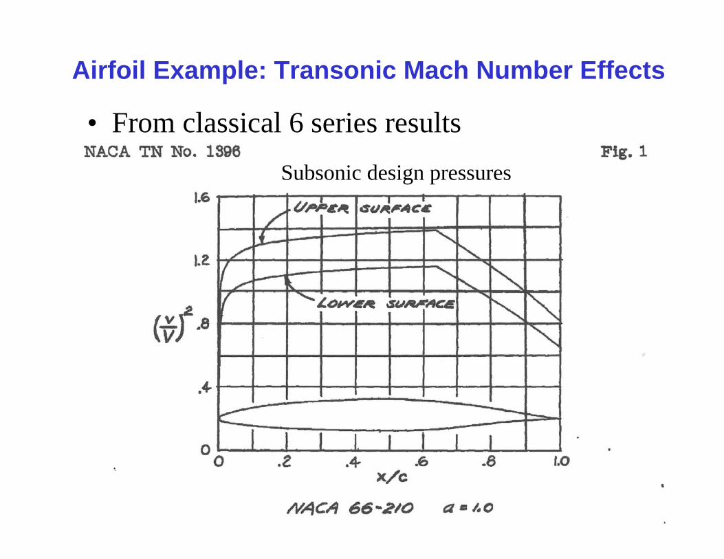
Airfoil Example: Transonic Mach Number Effects
• From classical 6 series results
Subsonic design pressures

Lift
From NACA TN 1396, by Donald Graham, Aug. 1947
NACA Ames1 x 3.5 ft 2D WT6 inch chord foil
Re ≈ 2 Mill

Drag
From NACA TN 1396, by Donald Graham, Aug. 1947
NACA Ames1 x 3.5 ft 2D WT6 inch chord foil
Re ≈ 2 Mill

Pitching Moment: a major problem!
From NACA TN 1396, by Donald Graham, Aug. 1947
NACA Ames1 x 3.5 ft 2D WT6 inch chord foil
Re ≈ 2 Mill

What s going on?The flow development illustration
From Aerodynamics for Naval Aviators by Hurt
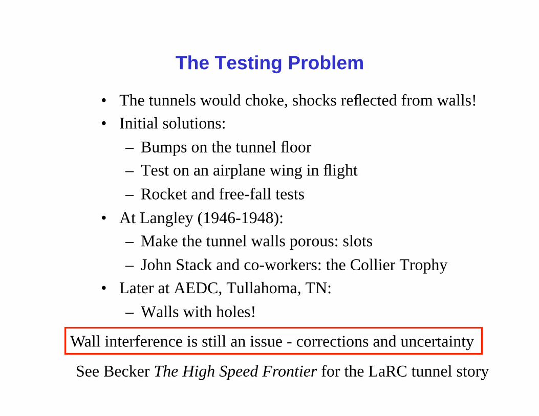
The Testing Problem
• The tunnels would choke, shocks reflected from walls!
• Initial solutions:
– Bumps on the tunnel floor
– Test on an airplane wing in flight
– Rocket and free-fall tests
• At Langley (1946-1948):
– Make the tunnel walls porous: slots
– John Stack and co-workers: the Collier Trophy
• Later at AEDC, Tullahoma, TN:
– Walls with holes!
Wall interference is still an issue - corrections and uncertainty
See Becker The High Speed Frontier for the LaRC tunnel story

Wall Interference Solution 1: Slotted Tunnel
Grumman blow-down pilot of Langley tunnel

Wall Interference Solution 2: Porous Wall
The AEDC 4T, Tullahoma, TN

The Next Problem: Flow Similarity- particularly critical at transonic speed -
• Reynolds Number (Re)– To simulate the viscous effects correctly, match the
Reynolds Number
– Usually you can t match the Reynolds number, we ll show you why and what aeros do about the problem
• Mach Number (M)– To match model to full scale compressibility effects, test
at the same Mach number, sub-scale and full scale
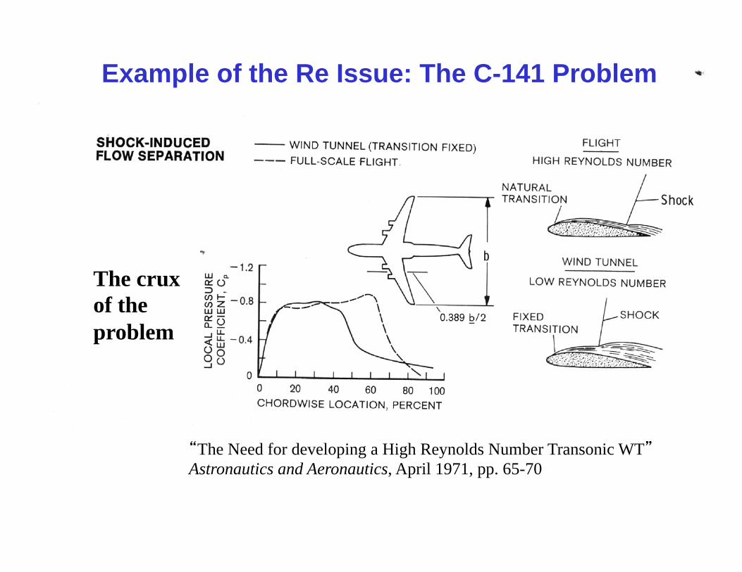
Example of the Re Issue: The C-141 Problem
The Need for developing a High Reynolds Number Transonic WTAstronautics and Aeronautics, April 1971, pp. 65-70
The crux of the problem

To Help Match Reynolds Number
– Pressure Tunnels
– Cold Tunnels• Keeps dynamic pressure reasonable
– Implies acceptable balance forces– Also reduces tunnel power requirements
– Big Wind Tunnels
– Games with the boundary layer• Force transition from laminar to turbulent flow: trips
- or a combination of the above -

Example: Oil Flow of a transport wing showing both the location of the transition
strip and the shock at M = 0.825
Transition strip
Shock Wave

Matching the Reynolds Number?
Re =ρVLμ
ρ : density, V: velocity, L : length, μ : viscosity,
Re =γ pML
R T 1.4
Use perfect gas law, and μ = T0.9
Increase Re by increasing p or L, decreasing T or changing the gas
Balance forces are related to, say, N = qSCL
q =γ2
pM 2
Reducing T allows Re increase without huge balance forces- note: q proportional to p, as shown above
AIAA 72-995 or Prog. in Aero. Sciences, Vol. 29, pp. 193-220, 1992
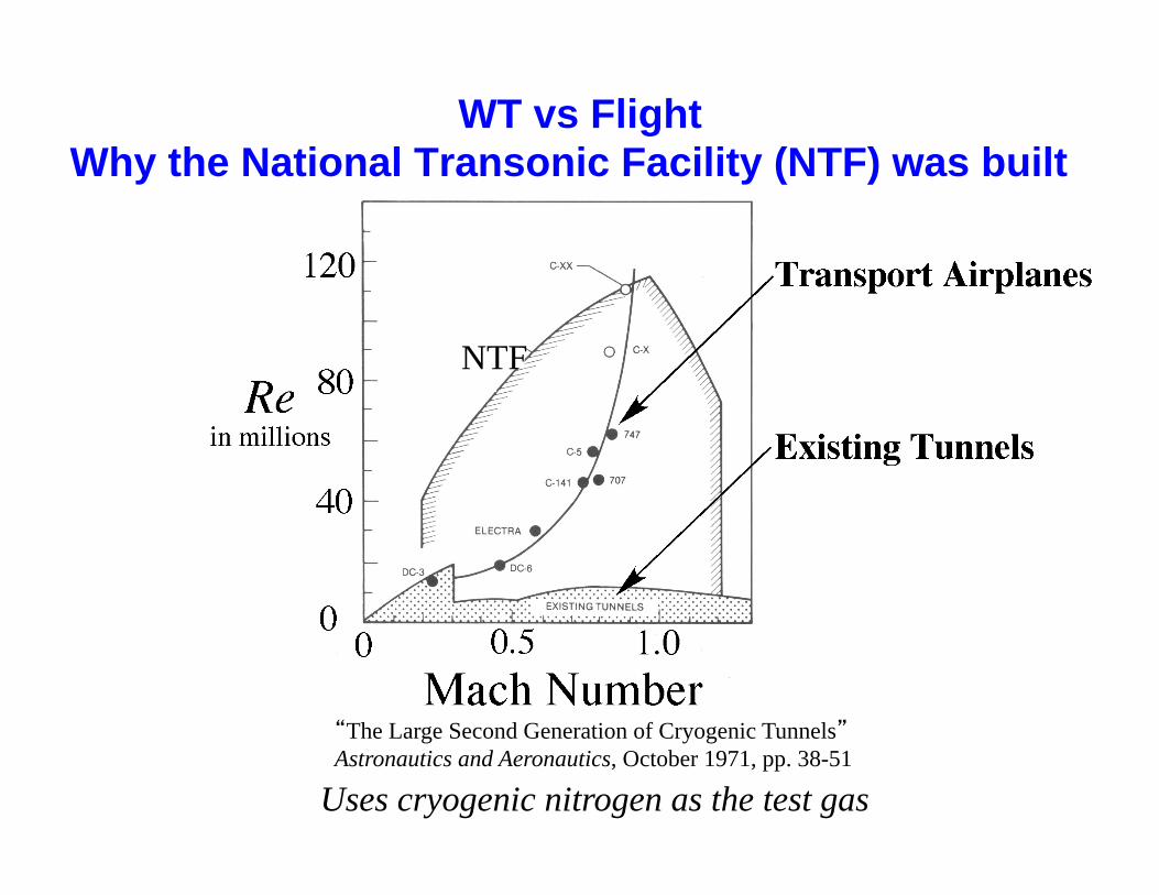
The Large Second Generation of Cryogenic TunnelsAstronautics and Aeronautics, October 1971, pp. 38-51
NTF
Uses cryogenic nitrogen as the test gas
WT vs FlightWhy the National Transonic Facility (NTF) was built

Trying to match flight Re using cryogenic nitrogen: The NTF at NASA Langley, Hampton, VA
Performance: M = 0.2 to 1.20PT = 1 to 9 atmTT = 77° to 350° Kelvin
Feb. 1982
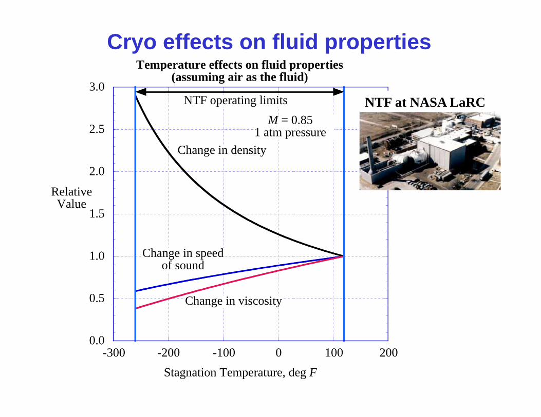
Cryo effects on fluid properties
0.0
0.5
1.0
1.5
2.0
2.5
3.0
-300 -200 -100 0 100 200
Temperature effects on fluid properties(assuming air as the fluid)
RelativeValue
Stagnation Temperature, deg F
Change in viscosity
Change in density
Change in speedof sound
M = 0.851 atm pressure
NTF operating limits NTF at NASA LaRC

0.0
1.0
2.0
3.0
4.0
5.0
-300 -200 -100 0 100 200
Temperature effects on Reynolds Numberand test dynamic pressure
RelativeValue
Stagnation Temperature, deg F
M = 0.851 atm pressure
NTF operating limits
Change inReynolds Number
Change in dynamic pressure
Cryo Effects on Re and q
NTF at NASA LaRC

Some References
Michael J. Goodyer and Robert A. Kilgore, High-Reynolds-Number Cryogenic Wind Tunnel, AIAA J., Vol. 11, No. 5, May 1973, pp. 613-619.
Dennis E. Fuller, Guide for Users of the National Transonic Facility, NASA TM 83124, July 1981.
Michael J. Goodyer, The Cryogenic Wind Tunnel, Progress in Aerospace Sciences, Vol. 29, pp. 193-220, 1992.