subsonic ultra-green aircraft research: transonic … · subsonic ultra-green aircraft research:...
TRANSCRIPT

1
SUBSONIC ULTRA-GREEN AIRCRAFT RESEARCH: TRANSONIC TRUSS-BRACED WING TECHNICAL
MATURATION
Christopher K. Droney*, Neal A. Harrison*, Gregory M. Gatlin** *The Boeing Company, **NASA Langley Research Center
Keywords: TTBW, Truss-Braced, Externally Braced, Vehicle Design
Abstract In 2009-2010, Boeing conducted the first phase of a Subsonic Ultra-Green Aircraft Research (SUGAR) study (1) in response to a NASA solicitation. In this study, Boeing identified and analyzed advanced concepts and technologies for aircraft that would fly in the 2030-2035 timeframe. Large possible improvements in fuel consumption, emissions, and noise were identified and roadmaps developed for key technologies. In this first phase of study, the Transonic Truss-Braced Wing (TTBW) vehicle concept was identified as having high potential for significant progress toward program requirements. In Phase II (2) of the program, partner Virginia Tech exercised a multidisciplinary optimization environment with Boeing participation and developed a TTBW wing planform with potential for significant reduction in fuel consumption relative to an equivalently configured 2008 fleet technology aircraft. Detailed aeroelastic analysis and a test in the NASA Transonic Dynamics Tunnel (TDT) (3) determined that aeroelastic impacts to TTBW designs are both manageable and analytically predictable. Wing weight corresponding to aspect ratios approaching 20 do not negate the aerodynamic benefit of increased span. Investigation of the TTBW high-speed aerodynamics was accomplished under SUGAR Phase III (4). The design cruise Mach number of the configuration was held at Mach 0.75 to remain consistent with minimum fuel consumption studies in previous phases. The cruise drag of the final configuration is approximately 6% lower than anticipated in
previous phases. The aerodynamic performance was validated in the 11-Foot Transonic Wind Tunnel facility of the Ames Unitary Plan Wind Tunnel (UPWT) complex. A Phase IV contract, focused on developing the outer mold line for both increased cruise speed (Mach 0.8) and high-lift system performance, was awarded in December of 2016. At the time of this writing, both the low and high-speed aerodynamics were proposed for testing at the Langley 14- by 22-Foot Subsonic Tunnel and Ames 11- by 11-Foot Transonic Wind Tunnel facility, respectively. Current performance predictions indicate the TTBW maintains an 8% fuel consumption advantage over an equivalently configured cantilever baseline.
1 Introduction and Background The NASA Advanced Air Vehicles Program (AAVP) investigates, evaluates, and develops technologies and capabilities suitable for future aircraft systems, while also exploring far-future concepts that hold promise for revolutionary air-travel improvements. Innovative AAVP design concepts for advanced vehicles integrate technologies that focus on safety, fuel consumption, noise, and emissions. The goal is to enable new aircraft to fly safer, faster, cleaner, quieter, and use fuel more efficiently. By partnering with industry, academia, and other government agencies, AAVP engages in mutually beneficial collaborations to leverage opportunities for effective technology transition.
Within the Advanced Air Vehicles Program, the Advanced Air Transport Technology (AATT) Project is exploring and developing technologies and concepts for improved energy efficiency and environmental compatibility for fixed wing
DRONEY, HARRISON, GATLIN
2
subsonic transports. The project vision is to enable development of aircraft with dramatically improved energy efficiency and environmental capability, thus providing a positive economic impact for the nation. The research being conducted will enable dramatic reductions in noise and emissions, and will increase performance characteristics via reducing fuel consumption of subsonic/transonic fixed wing aircraft. The AATT project pursues a multi-generational approach addressing the needs of today but with an emphasis on establishing the technological foundations necessary to enable the capabilities desired in the decades ahead. With this focus, NASA subsonic transport system level metrics/goals have been developed and are presented below in Table 1.
Table 1. NASA Subsonic Transport System Level Metrics/Goals (5).
TECHNOLOGY BENEFITS
TECHNOLOGY GENERATIONS
Technology Readiness Level = 5/6 Near Term
2015-2025
Mid Term
2025-2035
Far Term 2035+
Noise (cum below Stage 4) 22 – 32 dB 32 – 42 dB 42 – 52 dB
LTO NOx Emissions
(cum below CAEP 6) 70 – 75% 80% >80%
Cruise NOx Emissions
(rel. to 2005 best in class)
65 – 70% 80% >80%
Aircraft Fuel/Energy
Consumption (rel. to 2005 best in class)
40 – 50% 50 – 60% 60 – 80%
The Boeing Company shares NASA’s desire to increase aircraft safety, efficiency and minimize environmental and acoustic footprint. In 2009, Boeing stood up a Subsonic Ultra-Green Aircraft Research (SUGAR) team to work with NASA toward these objectives.
2 Concept Brainstorming and TTBW Formulation (Phase I) (1)
The preliminary phase of study included development of a comprehensive future scenario for world-wide commercial aviation, which
focused the team on a single-aisle-sized commercial transport. Fleet characteristics (utilization, size, etc.) and vehicle requirements (payload, range, etc.) were established in this exercise.
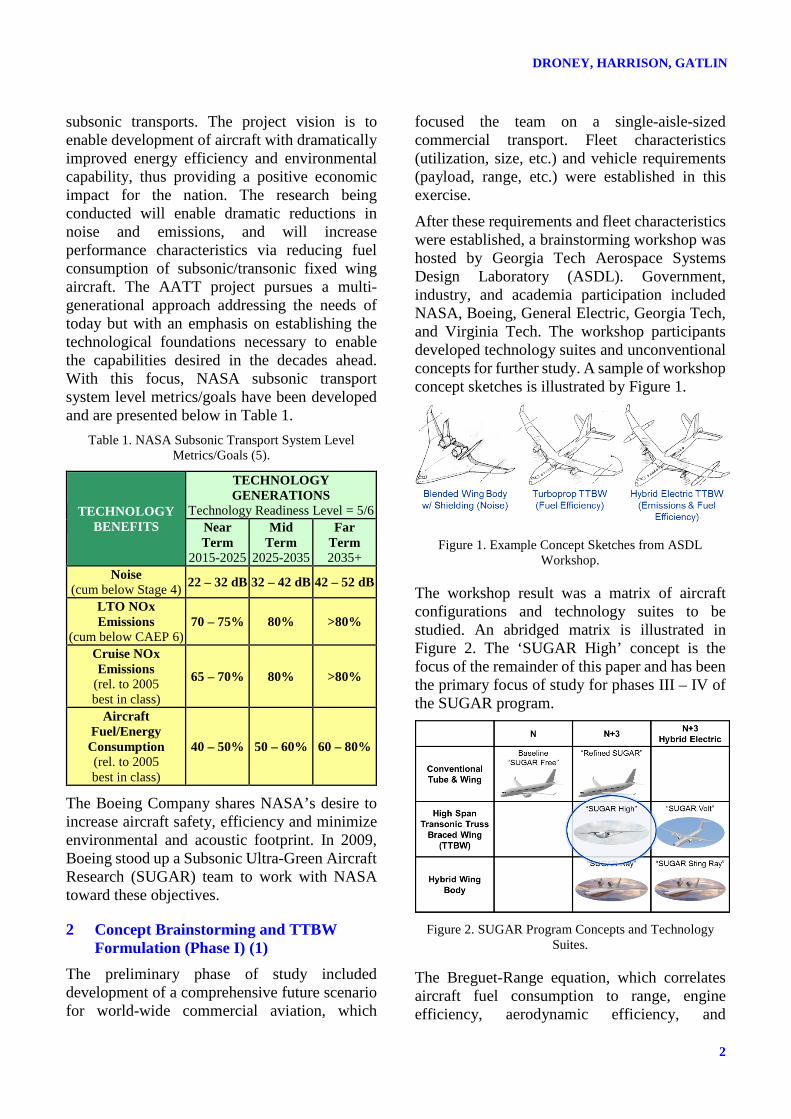
After these requirements and fleet characteristics were established, a brainstorming workshop was hosted by Georgia Tech Aerospace Systems Design Laboratory (ASDL). Government, industry, and academia participation included NASA, Boeing, General Electric, Georgia Tech, and Virginia Tech. The workshop participants developed technology suites and unconventional concepts for further study. A sample of workshop concept sketches is illustrated by Figure 1.
Figure 1. Example Concept Sketches from ASDL
Workshop.
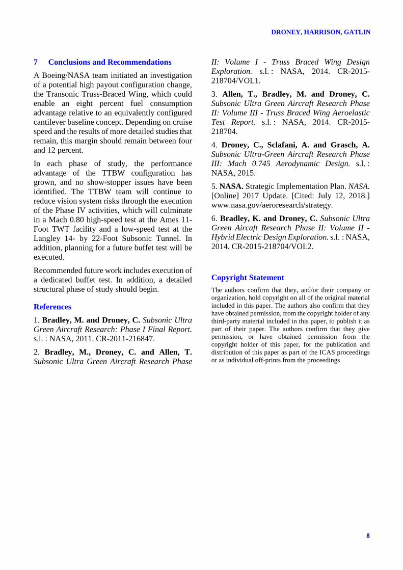
The workshop result was a matrix of aircraft configurations and technology suites to be studied. An abridged matrix is illustrated in Figure 2. The ‘SUGAR High’ concept is the focus of the remainder of this paper and has been the primary focus of study for phases III – IV of the SUGAR program.
Figure 2. SUGAR Program Concepts and Technology
Suites.
The Breguet-Range equation, which correlates aircraft fuel consumption to range, engine efficiency, aerodynamic efficiency, and

3
SUBSONIC ULTRA-GREEN AIRCRAFT RESEARCH: TRANSONIC TRUSS-BRACED WING TECHNICAL MATURATION
structural efficiency can be used to explain why the TTBW is of interest. Figure 3 illustrates the key terms and how they are affected by external bracing. For a given range requirement and a fuel minimization objective, the only remaining terms are aerodynamic efficiency and structural efficiency (assuming cruise altitude is constant).
Figure 3. TTBW and the Breguet-Range Equation.
For aerodynamic efficiency, it can be shown that lift-to-drag ratio is related to wetted aspect ratio (total span squared divided by total wetted area). For classic transports with conventional wingspans, this limits the lift-to-drag ratio in the range of approximately 18 to 22. The TTBW technology enables higher span through the use of external bracing. This increase in span can
extend the lift-to-drag ratio of transport aircraft to levels obtained by heritage sailplanes.
This aerodynamic efficiency increase is enabled by external bracing. The main strut element is very effective at limiting the wing bending loads and, depending on the specific configuration, the internal wing can be sized primarily by global column buckling.
A significant increase in wing aspect ratio and the corresponding addition of the strut poses significant new engineering challenges to a seemingly conventional configuration. These challenges are depicted in Figure 4. The landing gear and strut integration poses structural challenges while providing opportunity for load path synergy. Reduced wing chord causes the need for full chord engine pylons. The wing, strut, and jury-strut pose bird strike and damage tolerant design challenges. Wing thickness limitations afford challenges to the integration of subsystems and actuation while also imposing new restrictions in manufacturing. Many of these challenges have not yet been addressed by the research team.
The primary focus areas of study in the following phases were to characterize the nonlinear aeroelastic behavior of the configuration, quantify the levels of interference drag that could be obtained from this type of configuration, and to investigate the performance of traditional
Figure 4. TTBW Is a Step Function Change to the State-of-the-Art.

DRONEY, HARRISON, GATLIN
4
transport high-lift systems as applied to strutted wings of double conventional aspect ratio.
3 TTBW Structural Analysis and Test (Phase II) (2) (3)
In SUGAR Phase II, TTBW research continued starting with a Georgia Tech/Virginia Tech multidisciplinary optimization (MDO) environment, which led to a successful wing planform optimization. This MDO was used to develop the wing planform and strut-wing junction location and has been held constant for all downstream studies. Boeing developed a preliminary wing design in isolation from the strut to provide a seed point for further design. A detailed nonlinear aeroelastic FEM (Figure 5) was developed based on this geometry.
Figure 5. Phase II Aeroelastic FEM.
The geometry and the completed FEM analysis were used by NextGen to design the aeroelastic model. The model was constructed using traditional aeroelastic test methods, which included cruciform spars for the wing and strut,
both covered by segmented nonstructural skins. The layout of the model is illustrated in Figure 6. This model was tested in 2013 and 2014 in the NASA Transonic Dynamics Tunnel (TDT) facility (Figure 7).
Figure 6. Aeroelastic Wind Tunnel Model Layout.
Aeroelastic impacts on TTBW design were determined to be manageable and wing weight proved to be less than estimated in previous phases of study. Analysis accurately predicted flutter mechanisms and the results showed significant variation with different angles of attack. Angle of attack variations are modeled fairly accurately using a method that accounts for preload and large displacement effects. Analysis using theoretical doublet lattice aerodynamics did not produce the sharp decrease in flutter speed with Mach that was measured in the wind tunnel but did accurately predict minimum flutter speed. These predictions may not be accurate for different TTBW vehicle geometries and/or aerodynamic configurations. As a secondary test objective, the TTBW team developed an active flutter suppression system, which was successfully demonstrated during test execution.
2 Active Surfaces
Cruciform Wing Beam
Flow-ThruNacelle
Cruciform Strut
H-Section Jury Beam
Rigid Fuselage
Side-wall Mounted
Figure 7. TTBW in the Transonic Dynamics Tunnel at NASA Langley.

5
SUBSONIC ULTRA-GREEN AIRCRAFT RESEARCH: TRANSONIC TRUSS-BRACED WING TECHNICAL MATURATION
4 High-Speed Design and Test (Phase III) (4)
Following a preliminary investigation of the structural and aeroelastic stability of the TTBW from Phase II, the SUGAR team focused on validating aerodynamic estimates. In previous phases, these were derived from conceptual methods, which predict drag based on a database of designed shapes. An empirical database for TTBW strut-wing intersections is not known to exist and this study is oriented toward gaining the prerequisite data for lower-order design space exploration by exercising higher-order tools and ultimately a wind tunnel test. The detailed design exercise conducted during Phase III utilized modern Navier-Stokes based computational fluid dynamics tools and determined vehicle cruise drag to be within 1% of the Phase II conceptual estimate however, some disagreements exist on a component-by-component basis. Through the use of these high-fidelity methods, uncertainty in the predicted fuel consumption of the truss-braced wing configuration has been greatly reduced.
The main strut was found to account for approximately 10% of the total airplane drag, with interference effects between the wing and strut making up about 1% of the airplane drag. Aerodynamic operability requirements were fully satisfied at the cruise Mach number, but some uncertainty remains regarding buffet margin at the maximum operating Mach number.
A 4.5% scale wind tunnel model (Figure 8) has been constructed and tested in the Ames 11- by 11-Foot Transonic Wind Tunnel (11-Foot TWT) facility.
Test results show that drag rise data collected compares well with CFD prediction indicating that interference effects are minimal and that the truss system is not setting drag divergence Mach number. Stability and control data indicates the configuration compares well with pretest predictions in all areas except spoiler effectiveness at dive Mach number. Here, spoilers indicate reversal at low deflections, a phenomenon the test team has experienced in prior configurations that should clear at higher deflections. Test data at these higher deflections could not be generated to verify this due to model load limitations.
Drag buildup data from this phase shows mixed results with some model component increments matching and some that do not. The root cause for this has been determined to be an unacceptably high level of surface roughness that is unable to be closed via post-test analysis. This also caused the overall drag levels of the wind tunnel test data to be offset from the test predictions by approximately 30 counts at the design lift coefficient and Mach number.
The test team employed several methods of data collection requiring surface coatings including Pressure Sensitive Paint (PSP), Infrared (IR), and
Figure 8. Mach 0.75 Wind Tunnel Model Installed at the Ames 11-Foot TWT Facility.

DRONEY, HARRISON, GATLIN
6
Model Deformation Measurement (MDM) data. These techniques provided important data for the test due to the limited space available for physical pressure taps. In the future, surface roughness caused by using these techniques should be carefully considered during the test planning phase.
5 High-Lift System Development and Cruise Speed Extension
Work performed in Phase III was culminated with recommendations for future work including the development of an outer mold line (OML) that facilitates traditional single aisle cruise speeds. Mach 0.8 was chosen as a reasonable objective with Mach 0.78 being a threshold speed.
At the time of the writing of this paper, the high-speed lines are not completed, however, preliminary analysis, depicted in Figure 9, shows an aircraft with higher aerodynamic performance than achieved by the Phase III layout. The only changes made to the configuration were to facilitate higher speed. These include thickness and sweep for the wing and thickness and planform for the strut. The wing spanwise chord distribution, fuselage, horizontal, vertical, and engine fan diameter were held fixed for consistency between phases of study. The performance of the Mach 0.8 aircraft is surprisingly good relative to the Mach 0.75 configuration and indicates either increased
design experience with the configuration OR an aerodynamic layout advantage associated with wing sweep.
Figure 9. Phase IV High-Speed Design Status.
The development of the high-speed lines will culminate in an additional high-speed wind tunnel test during the first quarter of 2019 where both the Phase III and Phase IV OML’s will be tested. Figure 10 shows a preliminary test activity that was conducted in January 2018 along with several inset computational fluid dynamics solutions showing, from left to right, current solutions of the flap hinge fairings, high-lift system deployment, and wing body fairing. The high-speed lines development was conducted in parallel with a low-speed design and analysis activity.
These two tasks were coordinated to facilitate an overall aerodynamic optimization of the aircraft. The high-lift system focused on the development of the leading-edge Krueger and trailing-edge flap element. An objective of this study was to
Figure 10. Phase IV Design and Test Activity Snapshots.

7
SUBSONIC ULTRA-GREEN AIRCRAFT RESEARCH: TRANSONIC TRUSS-BRACED WING TECHNICAL MATURATION
simplify the high-lift system architecture and minimize overall vehicle fuel consumption. At the time of this writing, the high-lift system development is underway with a high-lift system test planned in the third quarter of 2019.
6 Steps for Continued Technical Maturation
A detailed roadmap has been developed for the maturation of the TTBW technology. This roadmap, illustrated in Figure 11, shows the technical milestones required to mature the TTBW technology to TRL 6, which will require a flight test demonstration. The figure highlights the focus of each of the aforementioned phases of study and in addition, shows the execution of a NASA funded Ultra-Efficient Subsonic Transport (UEST) Systems Requirements Review (SRR) that was concluded in the first quarter of 2017. The SRR contract concluded in a detailed plan for the execution of a TTBW demonstrator (Figure 12), which is focused on nonlinear aeroelastic and buffet margin risk reduction for a vision vehicle’s full operability envelope including cruise and dive Mach numbers.
In addition, a detailed assessment of low-speed handling qualities high-lift system performance will be performed. The detailed schedule outlined is contingent on funding being made available with the assumed authority to proceed (ATP) slated in 2019. The program preliminary design review (PDR) and critical design review (CDR) are currently scheduled for 2021 and
2022, respectively with the first flight occurring in the 2023 timeframe. Any slip in this milestone will be a one-to-one slip in the out-year schedule.
Two uninvestigated and nonflight-test related milestones remain on the roadmap. First, a dedicated buffet test is needed to validate buffet margin predictions, which are based on heritage cantilever wing designs. The high span and low chord create challenges when integrating instrumentation for full span models at scales compatible with the Ames 11-Foot TWT facility. Consequently, a half span dedicated buffet model is being investigated. Second, in addition to high-speed buffet, additional attention should be paid to the detailed integration and structural layout of the wing and strut. While global analyses have not indicated cause for concern from a loads and aeroelastic standpoint, the structural layout and sizing requires more detailed investigation with special attention given to probable damage sources and the damage tolerant design mentality that will support eventual certification.
Figure 11. TTBW Development Plan.
Figure 12. Conceptual TTBW Demonstrator.
DRONEY, HARRISON, GATLIN
8
7 Conclusions and Recommendations A Boeing/NASA team initiated an investigation of a potential high payout configuration change, the Transonic Truss-Braced Wing, which could enable an eight percent fuel consumption advantage relative to an equivalently configured cantilever baseline concept. Depending on cruise speed and the results of more detailed studies that remain, this margin should remain between four and 12 percent.
In each phase of study, the performance advantage of the TTBW configuration has grown, and no show-stopper issues have been identified. The TTBW team will continue to reduce vision system risks through the execution of the Phase IV activities, which will culminate in a Mach 0.80 high-speed test at the Ames 11-Foot TWT facility and a low-speed test at the Langley 14- by 22-Foot Subsonic Tunnel. In addition, planning for a future buffet test will be executed.
Recommended future work includes execution of a dedicated buffet test. In addition, a detailed structural phase of study should begin.
References 1. Bradley, M. and Droney, C. Subsonic Ultra Green Aircraft Research: Phase I Final Report. s.l. : NASA, 2011. CR-2011-216847.
2. Bradley, M., Droney, C. and Allen, T. Subsonic Ultra Green Aircraft Research Phase
II: Volume I - Truss Braced Wing Design Exploration. s.l. : NASA, 2014. CR-2015-218704/VOL1.
3. Allen, T., Bradley, M. and Droney, C. Subsonic Ultra Green Aircraft Research Phase II: Volume III - Truss Braced Wing Aeroelastic Test Report. s.l. : NASA, 2014. CR-2015-218704.
4. Droney, C., Sclafani, A. and Grasch, A. Subsonic Ultra-Green Aircraft Research Phase III: Mach 0.745 Aerodynamic Design. s.l. : NASA, 2015.
5. NASA. Strategic Implementation Plan. NASA. [Online] 2017 Update. [Cited: July 12, 2018.] www.nasa.gov/aeroresearch/strategy.
6. Bradley, K. and Droney, C. Subsonic Ultra Green Aircaft Research Phase II: Volume II - Hybrid Electric Design Exploration. s.l. : NASA, 2014. CR-2015-218704/VOL2.
Copyright Statement The authors confirm that they, and/or their company or organization, hold copyright on all of the original material included in this paper. The authors also confirm that they have obtained permission, from the copyright holder of any third-party material included in this paper, to publish it as part of their paper. The authors confirm that they give permission, or have obtained permission from the copyright holder of this paper, for the publication and distribution of this paper as part of the ICAS proceedings or as individual off-prints from the proceedings