transmission & driveline tm a - gtr-store.eu transmission & driveline c e f g h i j k l m...
TRANSCRIPT

TRANSMISSION & DRIVELINE
C
E
SECTION TMA
B
M
TTRANSAXLE & TRANSMISSION
F
G
H
I
J
K
L
M
N
O
P
CONTENTS
TRANSMISSION: GR6Z30A
BASIC INSPECTION .................................... 6
DIAGNOSIS AND REPAIR WORK FLOW ......... 6Work Flow (GT-R certified NISSAN dealer) ..............6Diagnostic Work Sheet (GT-R certified NISSAN dealer) .......................................................................7
INSPECTION AND ADJUSTMENT ..................... 8
TCM REPLACEMENT .................................................8TCM REPLACEMENT : Description .........................8TCM REPLACEMENT : Special Repair Require-ment ..........................................................................8
TRANSMISSION ASSEMBLY REPLACEMENT ........9TRANSMISSION ASSEMBLY REPLACEMENT : Description ................................................................9TRANSMISSION ASSEMBLY REPLACEMENT : Special Repair Requirement .....................................9
MAINTENANCE .........................................................11MAINTENANCE : Description .................................12MAINTENANCE : Special Repair Requirement ......12
FUNCTION DIAGNOSIS ..............................14
TRANSMISSION SYSTEM .................................14Structure (GT-R certified NISSAN dealer) ..............14Shift Mechanism (GT-R certified NISSAN dealer) ....16Operation Status and Control (GT-R certified NIS-SAN dealer) .............................................................19Main Device (GT-R certified NISSAN dealer) .........19Oil Pressure System (GT-R certified NISSAN dealer) .....................................................................27TCM System (GT-R certified NISSAN dealer) ........27Component Parts Location (GT-R certified NIS-SAN dealer) .............................................................38
ON BOARD DIAGNOSTIC (OBD) SYSTEM ......40Diagnosis Description (GT-R certified NISSAN dealer) .....................................................................40
DIAGNOSIS SYSTEM (TCM) ............................41CONSULT-III Function (GT-R certified NISSAN dealer) .....................................................................41
COMPONENT DIAGNOSIS .........................57
U1000 CAN COMM CIRCUIT ...........................57Description (GT-R certified NISSAN dealer) ...........57DTC Logic (GT-R certified NISSAN dealer) ............57Diagnosis Procedure (GT-R certified NISSAN dealer) .....................................................................57
P0700 TCM ........................................................58Description (GT-R certified NISSAN dealer) ...........58DTC Logic (GT-R certified NISSAN dealer) ............58Diagnosis Procedure (GT-R certified NISSAN dealer) .....................................................................60
P0705 RANGE SENSOR POWER SUPPLY ....62Description (GT-R certified NISSAN dealer) ...........62DTC Logic (GT-R certified NISSAN dealer) ............62Diagnosis Procedure (GT-R certified NISSAN dealer) .....................................................................63Component Inspection (Park Position Switch) (GT-R certified NISSAN dealer) ..............................67
P0706 RANGE SENSOR ..................................68Description (GT-R certified NISSAN dealer) ...........68DTC Logic (GT-R certified NISSAN dealer) ............68Diagnosis Procedure (GT-R certified NISSAN dealer) .....................................................................68Component Inspection (Park Position Switch) (GT-R certified NISSAN dealer) ..............................72
P0710 FLUID TEMPERATURE SENSOR ........73Description (GT-R certified NISSAN dealer) ...........73DTC Logic (GT-R certified NISSAN dealer) ............73Diagnosis Procedure (GT-R certified NISSAN dealer) .....................................................................73Component Inspection (Fluid Temperature Sen-sor) (GT-R certified NISSAN dealer) .......................75
www.gtr-
store
.eu
TM-1

P0711 FLUID TEMPERATURE SENSOR FUNCTION ......................................................... 76
Description (GT-R certified NISSAN dealer) ........... 76DTC Logic (GT-R certified NISSAN dealer) ............ 76Diagnosis Procedure (GT-R certified NISSAN dealer) .................................................................... 76Component Inspection (Fluid Temperature Sen-sor) (GT-R certified NISSAN dealer) ...................... 78
P0715 CLUTCH A SPEED SENSOR ................ 79Description (GT-R certified NISSAN dealer) ........... 79DTC Logic (GT-R certified NISSAN dealer) ............ 79Diagnosis Procedure (GT-R certified NISSAN dealer) .................................................................... 80
P0720 OUTPUT SHAFT SPEED SENSOR ....... 82Description (GT-R certified NISSAN dealer) ........... 82DTC Logic (GT-R certified NISSAN dealer) ............ 82Diagnosis Procedure (GT-R certified NISSAN dealer) .................................................................... 84
P0725 ENGINE SPEED SIGNAL ...................... 87Description (GT-R certified NISSAN dealer) ........... 87DTC Logic (GT-R certified NISSAN dealer) ............ 87Diagnosis Procedure (GT-R certified NISSAN dealer) .................................................................... 88
P0729 SLEEVE A1 FUNCTION ......................... 91Description (GT-R certified NISSAN dealer) ........... 91DTC Logic (GT-R certified NISSAN dealer) ............ 91Diagnosis Procedure (GT-R certified NISSAN dealer) .................................................................... 96
P0731 SLEEVE B1 FUNCTION ......................... 99Description (GT-R certified NISSAN dealer) ........... 99DTC Logic (GT-R certified NISSAN dealer) ............ 99Diagnosis Procedure (GT-R certified NISSAN dealer) ...................................................................104
P0732 SLEEVE A2 FUNCTION ....................... 108Description (GT-R certified NISSAN dealer) ..........108DTC Logic (GT-R certified NISSAN dealer) ...........108Diagnosis Procedure (GT-R certified NISSAN dealer) ...................................................................114
P0733 SLEEVE B2 FUNCTION ....................... 117Description (GT-R certified NISSAN dealer) ..........117DTC Logic (GT-R certified NISSAN dealer) ...........117Diagnosis Procedure (GT-R certified NISSAN dealer) ...................................................................123
P0745 CLUTCH A SOLENOID VALVE ........... 126Description (GT-R certified NISSAN dealer) ..........126DTC Logic (GT-R certified NISSAN dealer) ...........126Diagnosis Procedure (GT-R certified NISSAN dealer) ...................................................................126Component Inspection (Clutch A Solenoid Valve) (GT-R certified NISSAN dealer) ............................128
P0746 CLUTCH A SOLENOID VALVE FUNC-TION ................................................................. 129
Description (GT-R certified NISSAN dealer) ......... 129DTC Logic (GT-R certified NISSAN dealer) .......... 129Diagnosis Procedure (GT-R certified NISSAN dealer) ................................................................... 130
P0750 SHIFT SOLENOID VALVE 1 .................132Description (GT-R certified NISSAN dealer) ......... 132DTC Logic (GT-R certified NISSAN dealer) .......... 132Diagnosis Procedure (GT-R certified NISSAN dealer) ................................................................... 132Component Inspection (Shift Solenoid Valve 1) (GT-R certified NISSAN dealer) ............................ 134
P0755 SHIFT SOLENOID VALVE 2 .................135Description (GT-R certified NISSAN dealer) ......... 135DTC Logic (GT-R certified NISSAN dealer) .......... 135Diagnosis Procedure (GT-R certified NISSAN dealer) ................................................................... 135Component Inspection (Shift Solenoid Valve 2) (GT-R certified NISSAN dealer) ............................ 137
P0760 SHIFT SOLENOID VALVE 3 .................138Description (GT-R certified NISSAN dealer) ......... 138DTC Logic (GT-R certified NISSAN dealer) .......... 138Diagnosis Procedure (GT-R certified NISSAN dealer) ................................................................... 138Component Inspection (Shift Solenoid Valve 3) (GT-R certified NISSAN dealer) ............................ 140
P0765 SHIFT SOLENOID VALVE 4 .................141Description (GT-R certified NISSAN dealer) ......... 141DTC Logic (GT-R certified NISSAN dealer) .......... 141Diagnosis Procedure (GT-R certified NISSAN dealer) ................................................................... 141Component Inspection (GT-R certified NISSAN dealer) ................................................................... 142
P0770 SEQUENCE SOLENOID VALVE ..........144Description (GT-R certified NISSAN dealer) ......... 144DTC Logic (GT-R certified NISSAN dealer) .......... 144Diagnosis Procedure (GT-R certified NISSAN dealer) ................................................................... 145Component Inspection (Sequence Solenoid Valve) (GT-R certified NISSAN dealer) ................. 146
P0775 CLUTCH B SOLENOID VALVE ............147Description (GT-R certified NISSAN dealer) ......... 147DTC Logic (GT-R certified NISSAN dealer) .......... 147Diagnosis Procedure (GT-R certified NISSAN dealer) ................................................................... 147Component Inspection (Clutch B Solenoid Valve) (GT-R certified NISSAN dealer) ............................ 149
P0776 CLUTCH B SOLENOID VALVE FUNC-TION ..................................................................150
Description (GT-R certified NISSAN dealer) ......... 150DTC Logic (GT-R certified NISSAN dealer) .......... 150Diagnosis Procedure (GT-R certified NISSAN dealer) ................................................................... 151
P0790 SET-UP SWITCH (TRANSMISSION) ...153
www.gtr-
store
.eu
TM-2

C
E
F
G
H
I
J
K
L
M
A
B
M
N
O
P
T
Description (GT-R certified NISSAN dealer) ......... 153DTC Logic (GT-R certified NISSAN dealer) .......... 153Diagnosis Procedure (GT-R certified NISSAN dealer) ................................................................... 153Component Inspection [Set-up Switch (Transmis-sion)] (GT-R certified NISSAN dealer) .................. 154
P0795 AXIS A FEED PRESSURE SOLENOID VALVE .............................................................. 155
Description (GT-R certified NISSAN dealer) ......... 155DTC Logic (GT-R certified NISSAN dealer) .......... 155Diagnosis Procedure (GT-R certified NISSAN dealer) ................................................................... 155Component Inspection (Axis A Feed Pressure So-lenoid Valve) (GT-R certified NISSAN dealer) ...... 157
P0797 AXIS A FEED PRESSURE SOLENOID VALVE FUNCTION .......................................... 158
Description (GT-R certified NISSAN dealer) ......... 158DTC Logic (GT-R certified NISSAN dealer) .......... 158Diagnosis Procedure (GT-R certified NISSAN dealer) ................................................................... 158
P0827, P0828 AUTO/MANUAL RANGE CHANGE SWITCH ........................................... 160
Description (GT-R certified NISSAN dealer) ......... 160DTC Logic (GT-R certified NISSAN dealer) .......... 160Diagnosis Procedure (GT-R certified NISSAN dealer) ................................................................... 160Component Inspection (Auto/Manual Range Change Switch) (GT-R certified NISSAN dealer) .. 162
P0840 CLUTCH A PRESSURE SENSOR ....... 163Description (GT-R certified NISSAN dealer) ......... 163DTC Logic (GT-R certified NISSAN dealer) .......... 163Diagnosis Procedure (GT-R certified NISSAN dealer) ................................................................... 164
P0845 CLUTCH B PRESSURE SENSOR ....... 166Description (GT-R certified NISSAN dealer) ......... 166DTC Logic (GT-R certified NISSAN dealer) .......... 166Diagnosis Procedure (GT-R certified NISSAN dealer) ................................................................... 167
P0872, P0873 LINE PRESSURE SENSOR ..... 169Description (GT-R certified NISSAN dealer) ......... 169DTC Logic (GT-R certified NISSAN dealer) .......... 169Diagnosis Procedure (GT-R certified NISSAN dealer) ................................................................... 169
P0882 TCM POWER SUPPLY ......................... 172Description (GT-R certified NISSAN dealer) ......... 172DTC Logic (GT-R certified NISSAN dealer) .......... 172Diagnosis Procedure (GT-R certified NISSAN dealer) ................................................................... 172Component Inspection (TCM Relay) (GT-R certi-fied NISSAN dealer) .............................................. 174
P1705 ACCELERATOR PEDAL POSITION SIGNAL ............................................................ 175
Description (GT-R certified NISSAN dealer) .........175DTC Logic (GT-R certified NISSAN dealer) ..........175Diagnosis Procedure (GT-R certified NISSAN dealer) ...................................................................175
P2713 AXIS B FEED PRESSURE SOLENOID VALVE ............................................................. 176
Description (GT-R certified NISSAN dealer) .........176DTC Logic (GT-R certified NISSAN dealer) ..........176Diagnosis Procedure (GT-R certified NISSAN dealer) ...................................................................176Component Inspection (Axis B Feed Pressure So-lenoid Valve) (GT-R certified NISSAN dealer) .......178
P2714 AXIS B FEED PRESSURE SOLENOID VALVE FUNCTION ......................................... 179
Description (GT-R certified NISSAN dealer) .........179DTC Logic (GT-R certified NISSAN dealer) ..........179Diagnosis Procedure (GT-R certified NISSAN dealer) ...................................................................179
P2722 LUBRICATING FLOW SOLENOID VALVE ............................................................. 181
Description (GT-R certified NISSAN dealer) .........181DTC Logic (GT-R certified NISSAN dealer) ..........181Diagnosis Procedure (GT-R certified NISSAN dealer) ...................................................................181Component Inspection (Lubricating Flow Solenoid Valve) (GT-R certified NISSAN dealer) .................183
P2731 LINE PRESSURE SOLENOID VALVE . 184Description (GT-R certified NISSAN dealer) .........184DTC Logic (GT-R certified NISSAN dealer) ..........184Diagnosis Procedure (GT-R certified NISSAN dealer) ...................................................................185Component Inspection (Line Pressure Solenoid Valve) (GT-R certified NISSAN dealer) .................186
P2765 CLUTCH B SPEED SENSOR .............. 187Description (GT-R certified NISSAN dealer) .........187DTC Logic (GT-R certified NISSAN dealer) ..........187Diagnosis Procedure (GT-R certified NISSAN dealer) ...................................................................188
P2776 PADDLE SHIFTER (SHIFT-UP SWITCH) ......................................................... 190
Description (GT-R certified NISSAN dealer) .........190DTC Logic (GT-R certified NISSAN dealer) ..........190Diagnosis Procedure (GT-R certified NISSAN dealer) ...................................................................190Component Inspection [Paddle Shifter (Shift-up Switch)] (GT-R certified NISSAN dealer) ...............191
P2780 PADDLE SHIFTER (SHIFT-DOWN SWITCH) ......................................................... 192
Description (GT-R certified NISSAN dealer) .........192DTC Logic (GT-R certified NISSAN dealer) ..........192Diagnosis Procedure (GT-R certified NISSAN dealer) ...................................................................192
www.gtr-
store
.eu
TM-3

Component Inspection [Paddle Shifter (Shift-down Switch)] (GT-R certified NISSAN dealer) .....193
MAIN POWER SUPPLY .................................. 194Description (GT-R certified NISSAN dealer) ..........194Diagnosis Procedure (GT-R certified NISSAN dealer) ...................................................................194
SET-UP SWITCH (TRANSMISSION) .............. 197Description (GT-R certified NISSAN dealer) ..........197Diagnosis Procedure (GT-R certified NISSAN dealer) ...................................................................197
SHIFT POSITION INDICATOR CIRCUIT ........ 199Description (GT-R certified NISSAN dealer) ..........199Diagnosis Procedure (GT-R certified NISSAN dealer) ...................................................................199
SHIFT LOCK SYSTEM .................................... 200Description (GT-R certified NISSAN dealer) ..........200Component Function Check (GT-R certified NIS-SAN dealer) ...........................................................200Diagnosis Procedure (GT-R certified NISSAN dealer) ...................................................................200Component Inspection (Stop Lamp Switch) (GT-R certified NISSAN dealer) .......................................204
ECU DIAGNOSIS .......................................205
TCM .................................................................. 205Reference Value (GT-R certified NISSAN dealer) ..205Wiring Diagram - TRANSMISSION CONTROL SYSTEM - (GT-R certified NISSAN dealer) ...........222Fail Safe (GT-R certified NISSAN dealer) .............230DTC Inspection Priority Chart (GT-R certified NIS-SAN dealer) ...........................................................232DTC Index .............................................................233
SYMPTOM DIAGNOSIS ............................235
TRANSMISSION CONTROL SYSTEM ........... 235Symptom Table (GT-R certified NISSAN dealer) ..235
PRECAUTION ............................................257
PRECAUTIONS ............................................... 257Precaution for Supplemental Restraint System (SRS) "AIR BAG" and "SEAT BELT PRE-TEN-SIONER" ................................................................257Aluminum Die-Casting Parts Handling ..................257General Precautions ..............................................258Precautions for Replacement of TCM and Trans-mission Assembly ..................................................258Precautions Before Performing Diagnosis .............258
PREPARATION ..........................................263
PREPARATION ............................................... 263Special Service Tools (GT-R certified NISSAN dealer) ...................................................................263
Commercial Service Tools (GT-R certified NIS-SAN dealer) .......................................................... 263
ON-VEHICLE MAINTENANCE .................265
TRANSMISSION OIL ........................................265Inspection .............................................................. 265Draining ................................................................. 266Filling ..................................................................... 266
SHIFT POSITION ..............................................268Inspection and Adjustment .................................... 268
FLY WHEEL HOUSING ASSEMBLY ...............269Inspection (GT-R certified NISSAN dealer) .......... 269
ON-VEHICLE REPAIR ..............................270
TCM ..................................................................270Exploded View (GT-R certified NISSAN dealer) ... 270Removal and Installation (GT-R certified NISSAN dealer) ................................................................... 270
CONTROL DEVICE ..........................................272Exploded View ...................................................... 272Removal and Installation ....................................... 272Disassembly and Assembly .................................. 273Inspection .............................................................. 274
CONTROL CABLE ...........................................275Exploded View (GT-R certified NISSAN dealer) ... 275Removal and Installation (GT-R certified NISSAN dealer) ................................................................... 275Inspection (GT-R certified NISSAN dealer) .......... 276
PADDLE SHIFTER ...........................................277Exploded View (GT-R certified NISSAN dealer) ... 277Removal and Installation (GT-R certified NISSAN dealer) ................................................................... 277
OIL PAN ............................................................279Exploded View ...................................................... 279Removal and Installation (GT-R certified NISSAN dealer) ................................................................... 279Inspection (GT-R certified NISSAN dealer) .......... 280
PARK POSITION SWITCH ...............................281Exploded View (GT-R certified NISSAN dealer) ... 281Removal and Installation (GT-R certified NISSAN dealer) ................................................................... 281Inspection (GT-R certified NISSAN dealer) .......... 282
HEAT EXCHANGER SYSTEM .........................283
HEAT EXCHANGER PIPING .................................. 283HEAT EXCHANGER PIPING : Exploded View (GT-R certified NISSAN dealer) ............................ 283HEAT EXCHANGER PIPING : Removal and In-stallation (GT-R certified NISSAN dealer) ............. 283HEAT EXCHANGER PIPING : Inspection (GT-R certified NISSAN dealer) ....................................... 284
www.gtr-
store
.eu
TM-4

C
E
F
G
H
I
J
K
L
M
A
B
M
N
O
P
T
HEAT EXCHANGER ............................................... 285HEAT EXCHANGER : Exploded View (GT-R cer-tified NISSAN dealer) ............................................ 285HEAT EXCHANGER : Removal and Installation (GT-R certified NISSAN dealer) ............................ 285HEAT EXCHANGER : Inspection (GT-R certified NISSAN dealer) ..................................................... 287
FRONT OIL SEAL ............................................ 288Exploded View (GT-R certified NISSAN dealer) ... 288Removal and Installation (GT-R certified NISSAN dealer) ................................................................... 288Inspection (GT-R certified NISSAN dealer) ........... 290
REMOVAL AND INSTALLATION ............. 291
TRANSMISSION ASSEMBLY ......................... 291Exploded View (GT-R certified NISSAN dealer) ... 291Removal and Installation (GT-R certified NISSAN dealer) ................................................................... 291Inspection (GT-R certified NISSAN dealer) ........... 292
FLY WHEEL HOUSING ASSEMBLY .............. 293Exploded View (GT-R certified NISSAN dealer) ... 293
Removal and Installation (GT-R certified NISSAN dealer) ...................................................................293
DISASSEMBLY AND ASSEMBLY ............ 297
TRANSMISSION ASSEMBLY ........................ 297Exploded View .......................................................297Disassembly and assembly (GT-R certified NIS-SAN dealer) ...........................................................297
SERVICE DATA AND SPECIFICATIONS (SDS) .......................................................... 299
SERVICE DATA AND SPECIFICATIONS (SDS) ............................................................... 299
General Specification ............................................299Vehicle Speed at Which Gear Shifting Occurs (GT-R certified NISSAN dealer) ............................300Solenoid Valve (GT-R certified NISSAN dealer) ...300Fluid Temperature Sensor (GT-R certified NIS-SAN dealer) ...........................................................300Flywheel Housing Assembly (GT-R certified NIS-SAN dealer) ...........................................................300
www.gtr-
store
.eu
TM-5

[TRANSMISSION: GR6Z30A]DIAGNOSIS AND REPAIR WORK FLOW
< BASIC INSPECTION >
BASIC INSPECTIONDIAGNOSIS AND REPAIR WORK FLOW
Work Flow (GT-R certified NISSAN dealer) INFOID:0000000004019816
1.OBTAIN INFORMATION ABOUT SYMPTOM
1. Refer to TM-7, "Diagnostic Work Sheet (GT-R certified NISSAN dealer)" and interview the customer toobtain as much malfunction information (conditions and environment when the malfunction occurred) aspossible when the customer brings the vehicle in.
2. Check the following:- Service history- Refer to TM-258, "Precautions Before Performing Diagnosis".- Harnesses and connectors malfunction. Refer to XX-XX, "*****".
>> GO TO 2.
2.CHECK DTC
1. Before checking the malfunction, check whether any DTC exists.2. If DTC exists, perform the following operations.- Record the DTC and freeze frame data. (Print out using CONSULT-III)- Erase DTCs.- Check that the root cause clarified with DTC and malfunction information described by the customer. TM-
235, "Symptom Table (GT-R certified NISSAN dealer)" is effective.3. Check the information of related TB (Technical Bulletin) and others also.Do malfunction information and/or DTC exist?Malfunction information and DTC exist.>>GO TO 3.Malfunction information exists but no DTC.>>GO TO 4.No malfunction information, but DTC exists.>>GO TO 5.
3.REPRODUCE MALFUNCTION SYMPTOM
Check any malfunctions described by the customer, except the transmission warning lamp illuminated orblinking, on the vehicle.Also inspect whether the symptom is a fail safe or normal operation. Refer to TM-230, "Fail Safe (GT-R certi-fied NISSAN dealer)".When a malfunction symptom is reproduced, the “Diagnostic Work Sheet” is effective. Refer to TM-7, "Diag-nostic Work Sheet (GT-R certified NISSAN dealer)". Check the causal relationship between the symptom and the conditions in which the malfunction described bythe customer occurs.
>> GO TO 5.
4.REPRODUCE MALFUNCTION SYMPTOM
Check the malfunction described by the customer on the vehicle.Also whether the symptom is a fail safe or normal operation. Refer to TM-230, "Fail Safe (GT-R certified NIS-SAN dealer)".When a malfunction symptom is reproduced, the “Diagnostic Work Sheet” is effective. Refer to TM-7, "Diag-nostic Work Sheet (GT-R certified NISSAN dealer)".Check the causal relationship between the symptom and the conditions in which the malfunction described bythe customer occurs.
>> GO TO 6.
5.PERFORM “DTC CONFIRMATION PROCEDURE”
Perform “DTC CONFIRMATION PROCEDURE” for the applicable DTC to check if DTC is detected again.Refer to TM-232, "DTC Inspection Priority Chart (GT-R certified NISSAN dealer)" if multiple DTCs aredetected, and then judge the order for performing the diagnosis.NOTE:
www.gtr-
store
.eu
TM-6

DIAGNOSIS AND REPAIR WORK FLOW[TRANSMISSION: GR6Z30A]
C
E
F
G
H
I
J
K
L
M
A
B
M
N
O
P
< BASIC INSPECTION >
T
If no DTC is detected, refer to the freeze frame data.Is any DTC detected?YES >> GO TO 7.NO >> Check according to XX-XX, "*****".
6.IDENTIFY MALFUNCTIONING SYSTEM WITH “DIAGNOSIS CHART BY SYMPTOM”
Use TM-235, "Symptom Table (GT-R certified NISSAN dealer)" from the symptom inspection result in step 4.Then identify procedure to perform the diagnosis based on possible causes and symptoms.
>> GO TO 8.
7.REPAIR OR REPLACE THE MALFUNCTIONING PARTS
Repair or replace the detected malfunctioning parts.Reconnect parts or connector after repairing or replacing, and then erase DTC if necessary.
>> GO TO 8.
8.FINAL CHECK
Perform “DTC CONFIRMATION PROCEDURE” again to check that the repair is correctly performed.Check that malfunctions obtained from the customer are not reproduced, referring to the symptom inspectionresult in step 3 or 4.Is DTC or malfunction symptom reproduced?YES-1 >> DTC is reproduced: GO TO 5.YES-2 >> Malfunction symptom is reproduced: GO TO 6.NO >> Before delivering the vehicle to the customer, check that DTC is erased.
Diagnostic Work Sheet (GT-R certified NISSAN dealer) INFOID:0000000004019817
DescriptionThere are many operating conditions that may cause a malfunctionof the transmission parts. By understanding those conditions prop-erly, a quick and exact diagnosis can be performed.In general, customers have their own criteria for a problem. There-fore, it is important to understand the symptom and status wellenough by interviewing the customer about the concerns carefully.In order to systemize all the information for the diagnosis, preparethe interview sheet referring to the interview points.In some cases, multiple conditions that appear simultaneously makethe transmission warning light blink, which causes a DTC to bedetected.
SEF907L
www.gtr-
store
.eu
TM-7

[TRANSMISSION: GR6Z30A]INSPECTION AND ADJUSTMENT
< BASIC INSPECTION >
INSPECTION AND ADJUSTMENTTCM REPLACEMENT
TCM REPLACEMENT : Description INFOID:0000000004110682
When TCM is replaced, learning must be performed.CAUTION:• Before TCM is replaced, it is necessary to acquire the IP characteristic data based on the information
read out from the malfunctioning TCM. For acquiring the IP characteristic data, refer to “CONSULT-IIIGT-R TCM CONFIGURATION MANUAL”.
• If no IP characteristic data can be acquired, it is necessary to replace TCM and the transmissionassembly as a set.
TCM REPLACEMENT : Special Repair Requirement INFOID:0000000004110683
CAUTION:• Before TCM is replaced, it is necessary to acquire the IP characteristic data based on the information
read out from the malfunctioning TCM. For acquiring the IP characteristic data, refer to “CONSULT-IIIGT-R TCM CONFIGURATION MANUAL”.
• If no IP characteristic data can be acquired, it is necessary to replace TCM and the transmissionassembly as a set.
1.ACQUIRE “IP CHARACTERISTICS DATA”
Acquire the IP characteristics data. Refer to “CONSULT-III GT-R TCM CONFIGURATION MANUAL”.
>> GO TO 2.
2.PERFORM “WRITE IP CHARACTERISTICS”
Perform “Write IP Chara - Replace TCM” in “Configuration”. Refer to TM-41, "CONSULT-III Function (GT-Rcertified NISSAN dealer)".
>> GO TO 3.
3.SET LEARNING CONDITION
With CONSULT-III1. Start the engine.2. Select “RANGE”, “ACCEL POSI SEN 1”, and “FLUID TEMP” in “Data Monitor”.3. Set the condition as per the following.
Is the learning condition fulfilled?YES >> GO TO 4.NO >> Go to 4 after the learning condition is fulfilled.
4.PERFORM “CLUTCH GEAR LEARNING”
With CONSULT-III1. Perform “CLUTCH GEAR LEARNING” in “Work support”.2. Select “Start”.CAUTION:The "CLUTCH GEAR LEARNING" must be completed at temperature within 50 – 90°C (122 – 194°F).The learning is not yet completed if the temperature condition is outside the specified value duringlearning.Is "completed" displayed?YES >> End of learningNO >> GO TO 5.
RANGE : P
ACCEL POSI SEN 1 : 0.0/8
FLUID TEMP : 50 – 85 °C (122 – 185°F)
www.gtr-
store
.eu
TM-8

INSPECTION AND ADJUSTMENT[TRANSMISSION: GR6Z30A]
C
E
F
G
H
I
J
K
L
M
A
B
M
N
O
P
< BASIC INSPECTION >
T
5.CHECK THE LEARNING CONDITION
With CONSULT-III1. Turn the ignition switch OFF, and wait for 15 seconds or more.2. Start the engine.3. Select “RANGE”, “ACCEL POSI SEN 1”, “FLUID TEMP”, “BATTERY VOLTAGE”, “ENGINE SPEED”,
“VEHICLE SPEED”, and “LINE PRESSURE” in “Data Monitor”.4. Check that the following learning condition is fulfilled.
Is the learning condition fulfilled?YES >> GO TO 6.NO >> Go to 6 after the learning condition is fulfilled.
6.PERFORM “ACTIVE TEST” (CLUTCH A SOLENOID)
With CONSULT-III1. Select “C/L A PRESS S/V” in “Active Test”.2. Select “CLUTCH A PRESS”, and “TGT CLUTCH A PRS”.3. Raise “CLUTCH A PRESS” to 1.0 MPa (10.2 kg/cm2, 145 psi), and then lower it to 0 MPa (0 kg/cm2, 0
psi).4. Check that “CLUTCH A PRESS” and “TGT CLUTCH A PRS” follow with an equal value.Do “CLUTCH A PRESS” and “TGT CLUTCH A PRS” follow with an equal value?YES >> GO TO 7.NO >> Check “Self Diagnostic Result” of “TRANSMISSION”.
7.PERFORM “ACTIVE TEST” (CLUTCH B SOLENOID)
With CONSULT-III1. Select “C/L B PRESS S/V” in “Active Test”.2. Select “CLUTCH B PRESS”, and “TGT CLUTCH B PRS”.3. Raise “CLUTCH B PRESS” to 1.0 MPa (10.2 kg/cm2, 145 psi), and then lower it to 0 MPa (0 kg/cm2, 0
psi).4. Check that “CLUTCH B PRESS” and “TGT CLUTCH B PRS” follow with an equal value.Do “CLUTCH B PRESS” and “TGT CLUTCH B PRS” follow with an equal value?YES >> GO TO 4.NO >> Check “Self Diagnostic Result” of “TRANSMISSION”.
TRANSMISSION ASSEMBLY REPLACEMENT
TRANSMISSION ASSEMBLY REPLACEMENT : Description INFOID:0000000004110684
When the transmission assembly is replaced, the learning must be performed.
TRANSMISSION ASSEMBLY REPLACEMENT : Special Repair RequirementINFOID:0000000004110685
1.ACQUIRE “IP CHARACTERISTICS DATA”
Acquire the IP characteristics data. Refer to “CONSULT-III GT-R TCM CONFIGURATION MANUAL”.
>> GO TO 2.
2.PERFORM “WRITE IP CHARACTERISTICS”
RANGE : P
ACCEL POSI SEN 1 : 0.0/8
FLUID TEMP : 50 – 85 °C (122 – 185°F)
BATTERY VOLTAGE : 11 V or more
ENGINE SPEED : 650 – 2,000 rpm
VEHICLE SPEED : 3.5 km/h (2 MPH) or less
LINE PRESSURE : 0.35 MPa (3.57 kg/cm2, 50.75 psi) or more
www.gtr-
store
.eu
TM-9

[TRANSMISSION: GR6Z30A]INSPECTION AND ADJUSTMENT
< BASIC INSPECTION >Perform “Write IP Chara - Replace TM” in “Configuration”. Refer to TM-41, "CONSULT-III Function (GT-R cer-tified NISSAN dealer)".
>> GO TO 3.
3.PREPARE BEFORE LEARNING
With CONSULT-III1. Turn the ignition switch ON.2. Check the set values of “ADJUST CLUTCH A CAPACITY”, “ADJUST CLUTCH B CAPACITY”, “CLUTCH
A TOUCH POINT”, and “CLUTCH B TOUCH POINT” in "Work support".Are the set values of all items 0?YES >> GO TO 4.NO >> GO TO 4 after the set values become 0.
4.PERFORM “DELETE GEAR POSITION LEARNING VALUE”
With CONSULT-III1. Select “DELETE GEAR POSITION LEARNING VALUE” in “Work support”.2. Select “Start”.Can the gear position learning value be erased?YES >> GO TO 5.NO >> Perform again, and if it cannot be erased, check the harnesses and connectors.
5.PERFORM “DELETE CLUTCH A LEARNING VALUE”
With CONSULT-III1. Select “DELETE CLUTCH A LEARNING VALUE” in “Work support”.2. Select “Start”.Can the clutch A learning value be erased?YES >> GO TO 6.NO >> Perform again, and if it cannot be erased, check the harnesses and connectors.
6.PERFORM “DELETE CLUTCH B LEARNING VALUE”
With CONSULT-III1. Select “DELETE CLUTCH B LEARNING VALUE” in “Work support”.2. Select “Start”.Can the clutch B learning value be erased?YES >> GO TO 7.NO >> Perform again, and if it cannot be erased, check the harnesses and connectors.
7.PERFORM “ERASE CLUTCH ENGAGEMENT PRESSURE CORRECTION VALUE”
With CONSULT-III1. Select “ERASE CLTCH ENGGMNT PRSSR CRRCTN” in “Work support”.2. Select “Start”.Can the clutch engagement pressure correction value be erased?YES >> GO TO 8.NO >> Perform again, and if it cannot be erased, check the harnesses and connectors.
8.SET LEARNING CONDITION
With CONSULT-III1. Start the engine.2. Select “RANGE”, “ACCEL POSI SEN 1”, and “FLUID TEMP” in “Data Monitor”.3. Set the condition as per the following.
Is the learning condition fulfilled?
RANGE : P
ACCEL POSI SEN 1 : 0.0/8
FLUID TEMP : 50 – 85 °C (122 – 185°F)
www.gtr-
store
.eu
TM-10

INSPECTION AND ADJUSTMENT[TRANSMISSION: GR6Z30A]
C
E
F
G
H
I
J
K
L
M
A
B
M
N
O
P
< BASIC INSPECTION >
T
YES >> GO TO 9.NO >> GO TO 9 after the learning condition is fulfilled.
9.PERFORM “CLUTCH GEAR LEARNING”
With CONSULT-III1. Perform “CLUTCH GEAR LEARNING” in “Work support”.2. Select “Start”.CAUTION:The "CLUTCH GEAR LEARNING" must be completed at temperature within 50 – 90°C (122 – 194°F).The learning is not yet completed if the temperature condition is outside the specified value duringlearning.Is "completed" displayed?YES >> End of learningNO >> GO TO 10.
10.CHECK THE LEARNING CONDITION
With CONSULT-III1. Turn the ignition switch OFF, and wait for 15 seconds or more.2. Start the engine.3. Select “RANGE”, “ACCEL POSI SEN 1”, “FLUID TEMP”, “BATTERY VOLTAGE”, “ENGINE SPEED”,
“VEHICLE SPEED”, and “LINE PRESSURE” in “Data Monitor”.4. Check that the following learning condition is fulfilled.
Is the learning condition fulfilled?YES >> GO TO 11.NO >> GO TO 9 after the learning condition is fulfilled.
11.PERFORM “ACTIVE TEST” (CLUTCH A SOLENOID)
With CONSULT-III1. Select “C/L A PRESS S/V” in the “Active Test”.2. Select “CLUTCH A PRESS”, and “TGT CLUTCH A PRS”.3. Raise “CLUTCH A PRESS” to 1.0 MPa (10.2 kg/cm2, 145 psi), and then lower it to 0 MPa (0 kg/cm2, 0
psi).4. Check that “CLUTCH A PRESS” and “TGT CLUTCH A PRS” follow with an equal value.Do “CLUTCH A PRESS” and “TGT CLUTCH A PRS” follow with an equal value?YES >> GO TO 12.NO >> Check “Self Diagnostic Result” of “TRANSMISSION”.
12.PERFORM “ACTIVE TEST” (CLUTCH B SOLENOID)
With CONSULT-III1. Select “C/L B PRESS S/V” in “Active Test”.2. Select “CLUTCH B PRESS”, and “TGT CLUTCH B PRS”.3. Raise “CLUTCH B PRESS” to 1.0 MPa (10.2 kg/cm2, 145 psi), and then lower it to 0 MPa (0 kg/cm2, 0
psi).4. Check that “CLUTCH B PRESS” and “TGT CLUTCH B PRS” follow with an equal value.Do “CLUTCH B PRESS” and “TGT CLUTCH B PRS” follow with an equal value?YES >> GO TO 9.NO >> Check “Self Diagnostic Result” of “TRANSMISSION”.
MAINTENANCE
RANGE : P
ACCEL POSI SEN 1 : 0.0/8
FLUID TEMP : 50 – 85 °C (122 – 185°F)
BATTERY VOLTAGE : 11 V or more
ENGINE SPEED : 650 – 2,000 rpm
VEHICLE SPEED : 3.5 km/h (2 MPH) or less
LINE PRESSURE : 0.35 MPa (3.57 kg/cm2, 50.75 psi) or more
www.gtr-
store
.eu
TM-11
[TRANSMISSION: GR6Z30A]INSPECTION AND ADJUSTMENT
< BASIC INSPECTION >
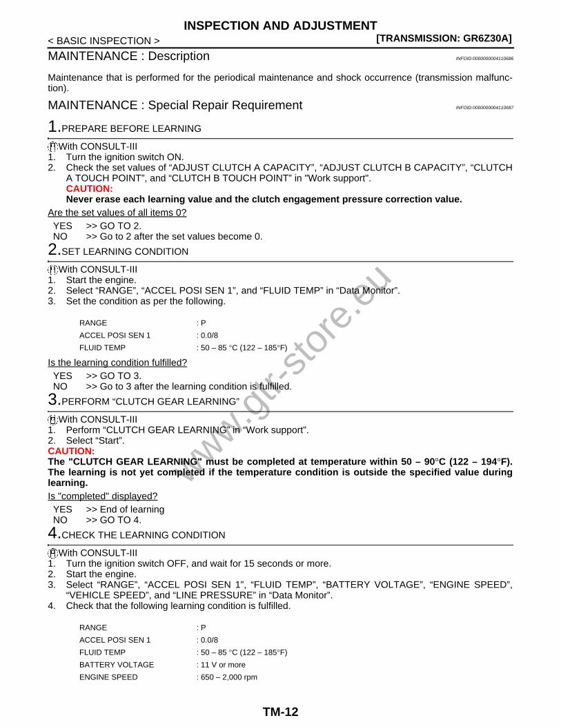
MAINTENANCE : Description INFOID:0000000004110686
Maintenance that is performed for the periodical maintenance and shock occurrence (transmission malfunc-tion).
MAINTENANCE : Special Repair Requirement INFOID:0000000004110687
1.PREPARE BEFORE LEARNING
With CONSULT-III1. Turn the ignition switch ON.2. Check the set values of “ADJUST CLUTCH A CAPACITY”, “ADJUST CLUTCH B CAPACITY”, “CLUTCH
A TOUCH POINT”, and “CLUTCH B TOUCH POINT” in "Work support".CAUTION:Never erase each learning value and the clutch engagement pressure correction value.
Are the set values of all items 0?YES >> GO TO 2.NO >> Go to 2 after the set values become 0.
2.SET LEARNING CONDITION
With CONSULT-III1. Start the engine.2. Select “RANGE”, “ACCEL POSI SEN 1”, and “FLUID TEMP” in “Data Monitor”.3. Set the condition as per the following.
Is the learning condition fulfilled?YES >> GO TO 3.NO >> Go to 3 after the learning condition is fulfilled.
3.PERFORM “CLUTCH GEAR LEARNING”
With CONSULT-III1. Perform “CLUTCH GEAR LEARNING” in “Work support”.2. Select “Start”.CAUTION:The "CLUTCH GEAR LEARNING" must be completed at temperature within 50 – 90°C (122 – 194°F).The learning is not yet completed if the temperature condition is outside the specified value duringlearning.Is "completed" displayed?YES >> End of learningNO >> GO TO 4.
4.CHECK THE LEARNING CONDITION
With CONSULT-III1. Turn the ignition switch OFF, and wait for 15 seconds or more.2. Start the engine.3. Select “RANGE”, “ACCEL POSI SEN 1”, “FLUID TEMP”, “BATTERY VOLTAGE”, “ENGINE SPEED”,
“VEHICLE SPEED”, and “LINE PRESSURE” in “Data Monitor”.4. Check that the following learning condition is fulfilled.
RANGE : P
ACCEL POSI SEN 1 : 0.0/8
FLUID TEMP : 50 – 85 °C (122 – 185°F)
RANGE : P
ACCEL POSI SEN 1 : 0.0/8
FLUID TEMP : 50 – 85 °C (122 – 185°F)
BATTERY VOLTAGE : 11 V or more
ENGINE SPEED : 650 – 2,000 rpm
www.gtr-
store
.eu
TM-12

INSPECTION AND ADJUSTMENT[TRANSMISSION: GR6Z30A]
C
E
F
G
H
I
J
K
L
M
A
B
M
N
O
P
< BASIC INSPECTION >
T
Is the learning condition fulfilled?YES >> GO TO 5.NO >> Go to 3 after the learning condition is fulfilled.
5.PERFORM “ACTIVE TEST” (CLUTCH A SOLENOID)
With CONSULT-III1. Select “C/L A PRESS S/V” in “Active Test”.2. Select “CLUTCH A PRESS”, and “TGT CLUTCH A PRS”.3. Raise “CLUTCH A PRESS” to 1.0 MPa (10.2 kg/cm2, 145 psi), and then lower it to 0 MPa (0 kg/cm2, 0
psi).4. Check that “CLUTCH A PRESS” and “TGT CLUTCH A PRS” follow with an equal value.Do “CLUTCH A PRESS” and “TGT CLUTCH A PRS” follow with an equal value?YES >> GO TO 6.NO >> Check “Self Diagnostic Result” of “TRANSMISSION”.
6.PERFORM “ACTIVE TEST” (CLUTCH B SOLENOID)
With CONSULT-III1. Select “C/L B PRESS S/V” in the “Active Test”.2. Select “CLUTCH B PRESS”, and “TGT CLUTCH B PRS”.3. Raise “CLUTCH B PRESS” to 1.0 MPa (10.2 kg/cm2, 145 psi), and then lower it to 0 MPa (0 kg/cm2, 0
psi).4. Check that “CLUTCH B PRESS” and “TGT CLUTCH B PRS” follow with an equal value.Do “CLUTCH B PRESS” and “TGT CLUTCH B PRS” follow with an equal value?YES >> GO TO 3.NO >> Check “Self Diagnostic Result” of “TRANSMISSION”.
VEHICLE SPEED : 3.5 km/h (2 MPH) or less
LINE PRESSURE : 0.35 MPa (3.57 kg/cm2, 50.75 psi) or more
www.gtr-
store
.eu
TM-13

[TRANSMISSION: GR6Z30A]TRANSMISSION SYSTEM
< FUNCTION DIAGNOSIS >
FUNCTION DIAGNOSISTRANSMISSION SYSTEM
Structure (GT-R certified NISSAN dealer) INFOID:0000000004019824
PERSPECTIVE VIEW
CROSS-SECTIONAL VIEW
1. Clutch A (even gear) 2. Clutch B (odd gear) 3. Transfer (E-TS)
4. Front reduction gear 5. Sleeve A1 (6th-Neutral synchroniz-er)
6. Sleeve A2 (2nd-4th synchronizer)
7. Sleeve B1 (1st-Reverse synchroniz-er)
8. Parking gear 9. Rear reduction gear
10. Rear final drive 11. 3rd gear 12. Sleeve B2 (3rd-5th synchronizer)
13. 5th gear 14. Reverse gear 15. 1st gear
16. 4th gear 17. 2nd gear 18. 6th gear
19. Actuator control module (Oil pres-sure control valve + Shift actuator)
20. Front control module (Oil pressure control valve + Oil pressure pump)
A. From main propeller shaft B. To front propeller shaft
NNDIA0081ZZ
www.gtr-
store
.eu
TM-14

TRANSMISSION SYSTEM[TRANSMISSION: GR6Z30A]
C
E
F
G
H
I
J
K
L
M
A
B
M
N
O
P
< FUNCTION DIAGNOSIS >
T
SYSTEM DIAGRAM
1. Clutch A (even gear) 2. Clutch B (odd gear) 3. Transfer (E-TS)
4. Front reduction gear 5. Sleeve A1 (6th-Neutral synchroniz-er)
6. Sleeve A2 (2nd-4th synchronizer)
7. Sleeve B1 (1st-Reverse synchroniz-er)
8. Parking gear 9. Rear reduction gear
10. Rear final drive 11. 3rd gear 12. Sleeve B2 (3rd-5th synchronizer)
13. 5th gear 14. Reverse gear 15. 1st gear
16. 4th gear 17. 2nd gear 18. 6th gear
NNDIA0082ZZ
www.gtr-
store
.eu
TM-15

[TRANSMISSION: GR6Z30A]TRANSMISSION SYSTEM
< FUNCTION DIAGNOSIS >
Shift Mechanism (GT-R certified NISSAN dealer) INFOID:0000000004019825
SYSTEM DIAGRAM
OPERATIONThe gear shift is mainly performed by the pre-shift and clutch release/engagement.
1. Clutch A (even gear) 2. Clutch B (odd gear) 3. Transfer (E-TS)
4. Front reduction gear 5. Sleeve A1 (6th-Neutral synchroniz-er)
6. Sleeve A2 (2nd-4th synchronizer)
7. Sleeve B1 (1st-Reverse synchroniz-er)
8. Parking gear 9. Rear reduction gear
10. Rear final drive 11. 3rd gear 12. Sleeve B2 (3rd-5th synchronizer)
13. 5th gear 14. Reverse gear 15. 1st gear
16. 4th gear 17. 2nd gear 18. 6th gear
NNDIA0083ZZ
JPDIA0906GB
www.gtr-
store
.eu
TM-16

TRANSMISSION SYSTEM[TRANSMISSION: GR6Z30A]
C
E
F
G
H
I
J
K
L
M
A
B
M
N
O
P
< FUNCTION DIAGNOSIS >
T
NOTE:• The pre-shift means that the gear on the clutch release side shifts to the next shift speed before a gear shift
occurs.• The clutch release/engagement means that while releasing the clutch on the gear position before gear shift,
the clutch on the gear position after gear shift is engaged during the gear shift.
Example: Shifting from 2nd gear to 3rd gear1. Running with 2nd gear- Shifting to the 2nd gear, clutch A is engaged and the 2nd gear is used to drive.
2. Pre-shift (3rd gear)- For preparation for shifting from 2nd to 3rd, shift to the 3rd gear.
3. Clutch release/engagement (gear shift from 2nd to 3rd)
JPDIA0907GB
JPDIA0908GB
www.gtr-
store
.eu
TM-17

[TRANSMISSION: GR6Z30A]TRANSMISSION SYSTEM
< FUNCTION DIAGNOSIS >- While releasing clutch A, engage clutch B.
4. Running with 3rd gear- Clutch B is engaged and the 3rd gear is used to drive.- If the next gear shift is a downshift, the 2nd gear remains engaged, if an upshift, the 2nd gear is released
and the 4th gear is engaged. (The figure shows the up side. Normal pre-shift is upshift.)
JPDIA0909GB
JPDIA0910GBwww.gtr-
store
.eu
TM-18

TRANSMISSION SYSTEM[TRANSMISSION: GR6Z30A]
C
E
F
G
H
I
J
K
L
M
A
B
M
N
O
P
< FUNCTION DIAGNOSIS >
T
Operation Status and Control (GT-R certified NISSAN dealer) INFOID:0000000004019826
*: Pre-shift (pre-shift means that the gear on the clutch release side shifts to the next speed before a gear shiftoccurs)
Main Device (GT-R certified NISSAN dealer) INFOID:0000000004019827
DUAL CLUTCH• It is equipped with 2 wet clutches, clutch A and clutch B, and each clutch is engaged or released by the
hydraulic piston.• If there is no oil pressure, the return spring forces the piston to return, releasing the clutch.
SHIFT DEVICE• Each synchronizer is activated by its own shift actuator (hydraulic cylinder).• Borg Warner type triple cone synchronizer is used for all the gear speeds.• A friction material is affixed to the cone surface of the synchronizer to allow higher capacity than a normal
cone made of copper alloy.• The actuator control module is a unit integrated with the shift actuator and hydraulic control valve.
Structure• Component parts location
JPDIA0911GB
www.gtr-
store
.eu
TM-19
[TRANSMISSION: GR6Z30A]TRANSMISSION SYSTEM
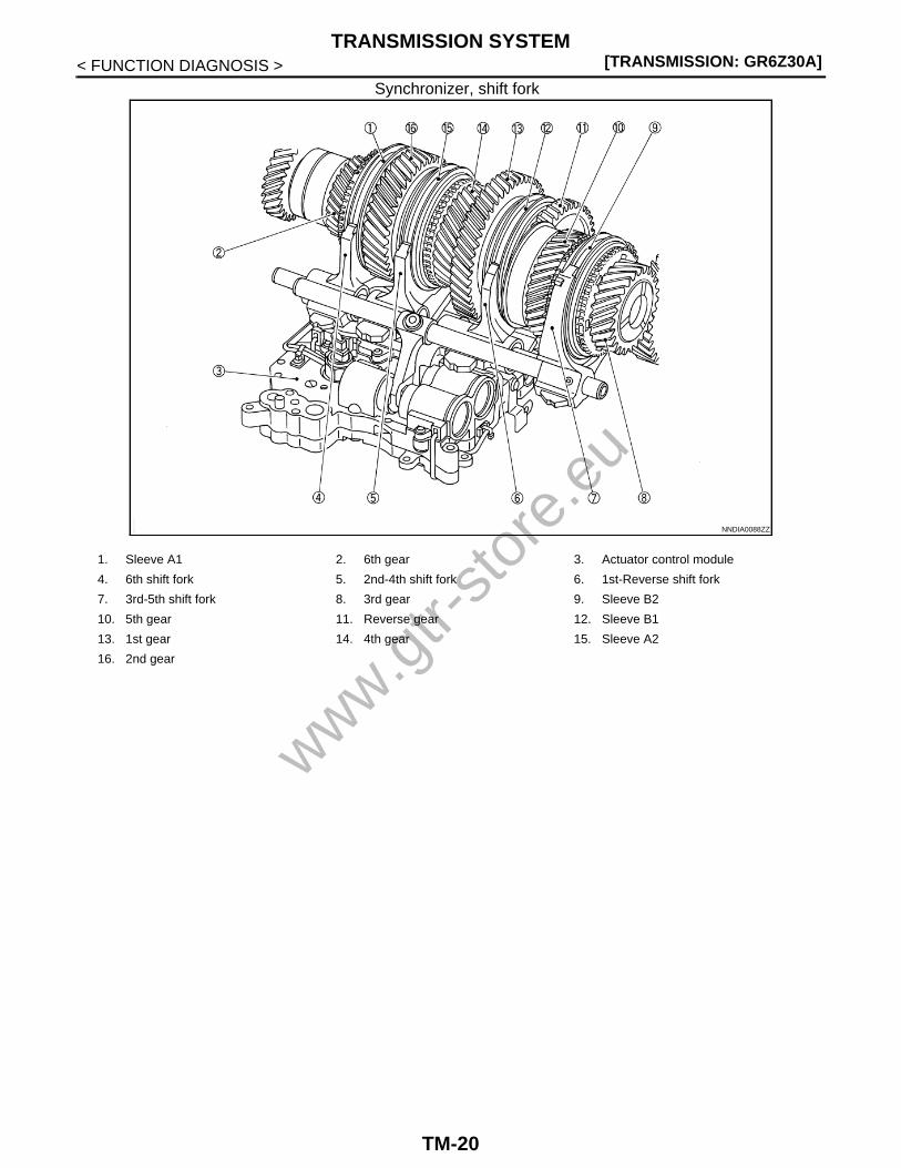
< FUNCTION DIAGNOSIS >Synchronizer, shift fork
NNDIA0088ZZ
1. Sleeve A1 2. 6th gear 3. Actuator control module
4. 6th shift fork 5. 2nd-4th shift fork 6. 1st-Reverse shift fork
7. 3rd-5th shift fork 8. 3rd gear 9. Sleeve B2
10. 5th gear 11. Reverse gear 12. Sleeve B1
13. 1st gear 14. 4th gear 15. Sleeve A2
16. 2nd gear
www.gtr-
store
.eu
TM-20
TRANSMISSION SYSTEM[TRANSMISSION: GR6Z30A]
C
E
F
G
H
I
J
K
L
M
A
B
M
N
O
P
< FUNCTION DIAGNOSIS >
T
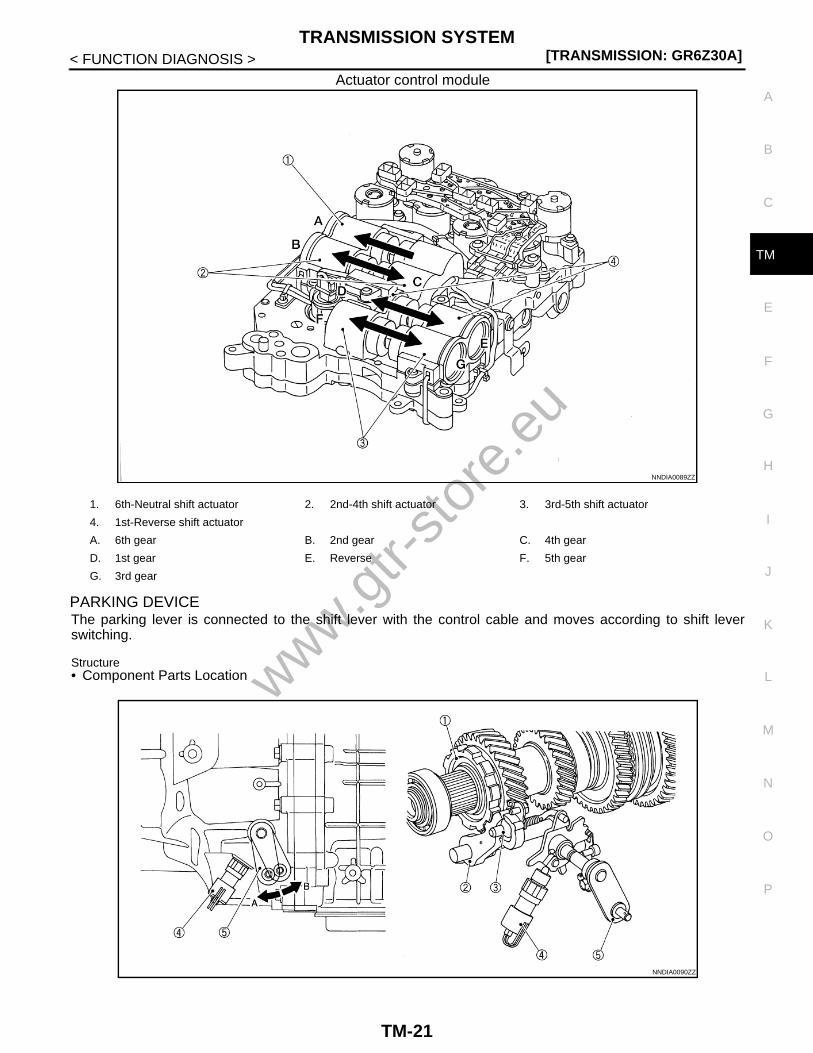
Actuator control module
PARKING DEVICEThe parking lever is connected to the shift lever with the control cable and moves according to shift leverswitching.
Structure• Component Parts Location
NNDIA0089ZZ
1. 6th-Neutral shift actuator 2. 2nd-4th shift actuator 3. 3rd-5th shift actuator
4. 1st-Reverse shift actuator
A. 6th gear B. 2nd gear C. 4th gear
D. 1st gear E. Reverse F. 5th gear
G. 3rd gear
NNDIA0090ZZ
www.gtr-
store
.eu
TM-21

[TRANSMISSION: GR6Z30A]TRANSMISSION SYSTEM
< FUNCTION DIAGNOSIS >
Operation• Operation diagram
Lock
Unlock
SHIFT LOCK DEVICE• In the shift lock status, pressing the knob button lowers the plate with the detent pin, then moves slider B, but
when the plate contacts slider A, it can no longer be lowered.• In the shift unlock status, sliders A and B are unified and the detent pin is moved out of P by lowered plate.
Structure• Component parts location
1. Parking gear 2. Parking pawl 3. Parking rod
4. Park position switch 5. Parking lever
NNDIA0091ZZ
1. Parking gear 2. Parking pawl 3. Parking rod
4. Park position switch 5. Parking lever
NNDIA0092ZZ
1. Parking gear 2. Parking pawl 3. Parking rod
4. Park position switch 5. Parking lever
www.gtr-
store
.eu
TM-22

TRANSMISSION SYSTEM[TRANSMISSION: GR6Z30A]
C
E
F
G
H
I
J
K
L
M
A
B
M
N
O
P
< FUNCTION DIAGNOSIS >
T
Operation• Operation diagram
Shift lock status
1. Plate 2. Detent pin 3. Slider A
4. Slider B
A. Detent gate
NNDIA0123ZZ
NNDIA0124ZZ
1. Plate 2. Detent pin 3. Slider A
4. Slider B
A. Detent gate
www.gtr-
store
.eu
TM-23

[TRANSMISSION: GR6Z30A]TRANSMISSION SYSTEM
< FUNCTION DIAGNOSIS >Shift unlock status
SHIFT LEVER• It inputs the range position (P, R, N, A⇔M) and Auto/Manual range
change switch signal to the TCM.• It is connected to the parking device of the transmission with the
control cable, and it locks the parking device only when the shiftlever is shifted into the P position.
PADDLE SHIFTER
NNDIA0125ZZ
1. Plate 2. Detent pin 3. Slider A
4. Slider B
A. Detent gate
NNDIA0114ZZ
www.gtr-
store
.eu
TM-24

TRANSMISSION SYSTEM[TRANSMISSION: GR6Z30A]
C
E
F
G
H
I
J
K
L
M
A
B
M
N
O
P
< FUNCTION DIAGNOSIS >
T
It inputs the switch signal of upshift or downshift to TCM.
Set-up switch (transmission)It inputs the switch signal of R mode or SNOW mode to TCM.
LUBRICATION DEVICE
Clutch lubricationIt lubricates clutches A and B with the hydraulic system.
Gear lubricationIt lubricates the gears, synchronizers, bearings and other sliding parts with the hydraulic system.
DISPLAY DEVICE
Information display
1 : Paddle shifter (shift-down switch)
2 : Paddle shifter (shift-up switch)
JPDIA0925ZZ
NNDIA0116ZZ
Message content Display timing Erasure procedure Remarks
T/M SYSTEM MALFUNCTION VISIT DEALER
When the check is necessary
• Turn the ignition switch ON again after turning OFF
• Erase the DTC using CON-SULT-III
Always blink the transmission warning light when this mes-sage is displayed
SHIFT TO THE P RANGE
• When the engine start opera-tion is performed in any range other than P or N
• When the engine starts while the shift lever is in N range and the gear is engaged
Shift the shift lever to the P range
—
CHECK POSITION OF SHIFT LEVER
When the shift lever position cannot be detected
Shift the shift lever into either range of P, R, N, A ⇔ M
—
T/M SYSTEM CHECK IN PRO-CESS
When the diagnosis is per-formed just after the engine starts while the shift lever is in the P range
Wait for a short period of time until the diagnosis is completed
While this message is dis-played, the shift lock solenoid prevents the shift lever from moving out of the P range
T/M OIL TEMP HIGH DE-CREASE SPEED
When the high oil temperature control is active because of high transmission fluid temperature
When the high oil temperature control is deactivated
Always illuminate the transmis-sion warning light when this message is displayed
T/M CLUTCH TEMP HIGH STOP VEHICLE UNTIL WARN-ING TURNS OFF
When the clutch protection con-trol is active because of high clutch temperature or stall driv-ing
When the clutch protection con-trol is deactivated
Always illuminate the transmis-sion warning light when this message is displayed
www.gtr-
store
.eu
TM-25

[TRANSMISSION: GR6Z30A]TRANSMISSION SYSTEM
< FUNCTION DIAGNOSIS >Shift position indicatorUpon receiving the CAN output signal from TCM, the drive gearposition appears and blinks, and the range is displayed.
Transmission warning lightIt illuminates and blinks with the CAN output signal from TCM.
Mode indicatorR mode lamp and SNOW mode lamp illuminate by the analog outputsignal from TCM.
Multi-function displayThe drive gear position, range position, transmission oil pressure and transmission oil temperature are dis-played by the CAN output signal from TCM.
A : Range position and drive gear position (A/M range)
B : A range or M range
NNDIA0119ZZ
ON : It shows an intermittent malfunction such as high transmission fluid temperature.
Blinking : It shows that a malfunction requiring a check occurs.
NNDIA0120ZZ
A : R mode lamp
B : SNOW mode lamp
NNDIA0121ZZ
JPDIA0897ZZ
www.gtr-
store
.eu
TM-26

TRANSMISSION SYSTEM[TRANSMISSION: GR6Z30A]
C
E
F
G
H
I
J
K
L
M
A
B
M
N
O
P
< FUNCTION DIAGNOSIS >
T
Oil Pressure System (GT-R certified NISSAN dealer) INFOID:0000000004019828
COMPONENT DESCRIPTION
TCM System (GT-R certified NISSAN dealer) INFOID:0000000004019829
WIRING DIAGRAM
A. Transmission oil temperature B. Transmission oil pressure C. Range position and drive gear posi-tion (A/M range)
D. A range or M range
Component Function
Suction filter Removes foreign matter contained in fluid and prevents them from entering the hydraulic circuitInline filter
Heat exchanger• Cools down fluid with the water-cooled cooler• When the engine starts at low temperature, warms fluid quickly
with heated coolant
Front control module
Oil pumpSucks fluid accumulated in the oil pan to build up oil pressure in the circuit
Valve
Line pressure valve• Controls the line pressure• The line pressure is adjusted by the line pressure solenoid
Clutch A solenoid valveControls the clutch pressure of clutch A/B
Clutch B solenoid valve
Lubricating flow valve• Controls the lubricating flow• The lubricating flow is adjusted by the lubricating flow solenoid
Clutch lubricating switching valve
Switches the lubricating distribution of the clutch.
Pressure sensor
Clutch A pressure sensorDetects the clutch pressure of clutch A/B
Clutch B pressure sensor
Actuator control module
Valve
Axis A feed pressure valve • Controls the feed pressure of axis A/B• Each feed pressure is adjusted by the axis A/B feed pressure
solenoidAxis B feed pressure valve
Shift solenoid valve 1
Controls 4 shift actuator pistons by combining ON and OFF of each shift solenoid valve and switching the sequence valve circuit
Shift solenoid valve 2
Shift solenoid valve 3
Shift solenoid valve 4
Sequence valve
Pressure sensor
Line pressure sensor Detects the line pressurewww.g
tr-sto
re.e
u
TM-27

[TRANSMISSION: GR6Z30A]TRANSMISSION SYSTEM
< FUNCTION DIAGNOSIS >
JCDWA0235GB
www.gtr-
store
.eu
TM-28

TRANSMISSION SYSTEM[TRANSMISSION: GR6Z30A]
C
E
F
G
H
I
J
K
L
M
A
B
M
N
O
P
< FUNCTION DIAGNOSIS >
T
JCDWA0236GB
www.gtr-
store
.eu
TM-29

[TRANSMISSION: GR6Z30A]TRANSMISSION SYSTEM
< FUNCTION DIAGNOSIS >
COMPONENT DESCRIPTION
JCDWA0237GB
www.gtr-
store
.eu
TM-30

TRANSMISSION SYSTEM[TRANSMISSION: GR6Z30A]
C
E
F
G
H
I
J
K
L
M
A
B
M
N
O
P
< FUNCTION DIAGNOSIS >
T
Component Function
Front control module
Valve
Line pressure solenoid valve
Controls the line pressure by the line pressure solenoid current
Clutch A solenoid valve
Controls the clutch pressure of clutches A/B by the clutch A/B solenoid currentClutch B solenoid valve
Lubricating flow solenoid valve
Controls the lubricating flow by the lubricating flow sole-noid current
Pressure sensor
Clutch A pressure sensor
Converts the clutch pressure of clutches A/B into voltageClutch B pressure sensor
JPDIA0915GB
JPDIA0916GB
JPDIA0917GB
JPDIA0918GB
www.gtr-
store
.eu
TM-31

[TRANSMISSION: GR6Z30A]TRANSMISSION SYSTEM
< FUNCTION DIAGNOSIS >
Actuator control module
Valve
Axis A feed pressure sole-noid valve
Controls the feed pressure of axes A/B by the axes A/B feed pressure solenoidAxis B feed pressure sole-
noid valve
Shift solenoid valve 1
Controls 4 shift actuator pistons by combining ON and OFF of
each shift solenoid valve*1
Shift solenoid valve 2
Shift solenoid valve 3
Shift solenoid valve 4
Sequence solenoid valve
Pressure sensor
Line pressure sensorConverts the line pressure into voltage
Position sensor
1st-Reverse position sen-sor 1 • Converts each shift actua-
tor position into voltage• Two 1st-reverse position
sensors with the same out-put (but the output charac-teristics are inverse) are installed for fail-safe
1st-Reverse position sen-sor 1
2nd-4th position sensor
6th-Neutral position sensor
3rd-5th position sensor
Wheel sensor
Clutch A speed sensorConverts the clutches A/B speed into pulse
Clutch B speed sensor
Output shaft speed sensor Converts the output shaft speed into pulse
Park position switchWhen the parking position is locked, it is energized, and when un-locked, it is not energized
Fluid temperature sensorConverts the oil pan oil tem-perature into electrical resis-tance
TCM Controls the transmission system
Shift device
Range sensor
Range sensor No. 0
With 6 range sensors, the shift lever position is recognized*2
Range sensor No. 1
Range sensor No. 2
Range sensor No. 3
Range sensor No. 4
Range sensor No. 5
Auto/Manual range change switch Inputs the Auto/Manual range change switch signal to TCM
Shift lock solenoidLock or unlock is attained with 3 systems, the ignition switch sig-nal, stop lamp switch signal and lock or unlock signal (TCM)
Component Function
JPDIA0919GB
JPDIA0920GB
JPDIA0921GB
JPDIA0922GB
www.gtr-
store
.eu
TM-32

TRANSMISSION SYSTEM[TRANSMISSION: GR6Z30A]
C
E
F
G
H
I
J
K
L
M
A
B
M
N
O
P
< FUNCTION DIAGNOSIS >
T
*1: For the combination of the solenoids, refer to the “Shift actuator operation list”.
*2: For the combination of the range sensors, refer to the “Shift lever position and range sensor output”.
Shift actuator operation list–: No effect on operation
Shift lever position and range sensor output
INPUT/OUTPUT SIGNAL LIST
Set-up switch
R mode switchNormally not energized, and energized by turning the set-up switch to R
SNOW mode switchNormally not energized, and energized by turning the set-up switch to SNOW
TCM relay Perform the power supply to TCM
Component Function
Shift actuator OperationSolenoid valve
Sequence Shift 1 Shift 2 Shift 3 Shift 4
6th-Neutral shift actuator6th gear → N
ONON OFF – –
6th gear ← N OFF ON – –
2nd-4th shift actuator2nd gear → N → 4th gear
OFFON OFF – –
2nd gear ← N ← 4th gear OFF ON – –
3rd-5th shift actuator5th gear → N → 3rd gear
ON– – OFF ON
5th gear ← N ← 3rd gear – – ON OFF
1st-Reverse shift actuator1st gear → N → Reverse
OFF– – ON OFF
1st gear ← N ← Reverse – – OFF ON
Shift lever positionRange sensor
No. 0 No. 1 No. 2 No. 3 No. 4 No. 5
P ON OFF OFF OFF OFF OFF
R OFF ON ON OFF OFF OFF
N OFF OFF ON ON ON OFF
A⇔M OFF OFF OFF OFF ON ON
www.gtr-
store
.eu
TM-33

[TRANSMISSION: GR6Z30A]TRANSMISSION SYSTEM
< FUNCTION DIAGNOSIS >
: Directly related : Indirectly related
Items
Control
Hydraulic solenoid valve control Gear shift control
Clutch Shift
Line
pre
ssur
e
Fee
d pr
essu
re
Clu
tch
lubr
icat
ion
Adaptive shift control
Blip
ping
con
trol
Pre
dict
ive
pre-
shift
con
trol
Aut
o up
shift
and
dow
nshi
ft
Sta
ndby
Sta
rt-u
p
Gea
r sh
ift
Lock
up
Clu
tch
touc
h po
int l
earn
ing
Shi
ft
Gea
r po
sitio
n se
nsor
lear
ning
Aut
o do
wns
hift
Gea
r fix
ed
Shi
ft pa
ttern
sw
itchi
ng
Out
put s
igna
l
Clutch A pressure solenoid valve
Clutch B pressure solenoid valve
Line pressure solenoid valve
Lubricating flow solenoid valve
Shift solenoid valve 1
Shift solenoid valve 2
Shift solenoid valve 3
Shift solenoid valve 4
Sequence solenoid valve
Axis A feed pressure solenoid valve
Axis B feed pressure solenoid valve
Engine torque down request*1
www.gtr-
store
.eu
TM-34

TRANSMISSION SYSTEM[TRANSMISSION: GR6Z30A]
C
E
F
G
H
I
J
K
L
M
A
B
M
N
O
P
< FUNCTION DIAGNOSIS >
T
*1: CAN signal (ECM)
*2: CAN signal [ABS actuator and electric unit (control unit)]
CONTROL
Clutch control• With no gear shift- The inactive-side (the side with no power transmission) clutch is fully released (zero pressure).- The active side (the side with power transmission) is controlled as per the following depending on the situa-
tion.• Standby: In A/M range or R range, with the accelerator pedal OFF, the pressure is built up until just before
the clutch is engaged (at brake ON), or partial clutch engagement status is reached (at brake OFF) toincrease the start-up response.
• Start-up: Pressure is controlled depending on the engine speed for smooth start-up and stop.• Lockup (with low output shaft speed): Slip lockup (the pressure is controlled so that the clutches have a
small speed difference to increase the noise and vibration performance).
Inpu
t sig
nal
Range signal
Stop lamp switch
Clutch A pressure
Clutch B pressure
1st-Reverse position 1
1st-Reverse position 1
2nd-4th position
3rd-5th position
6th-Neutral position
Clutch A speed
Clutch B speed
Output shaft speed
Park position switch
Oil temperature
Engine speed
Engine speed*1
Engine torque*1
Throttle position*1
Side G sensor signal*2
Items
Control
Hydraulic solenoid valve control Gear shift control
Clutch Shift
Line
pre
ssur
e
Fee
d pr
essu
re
Clu
tch
lubr
icat
ion
Adaptive shift control
Blip
ping
con
trol
Pre
dict
ive
pre-
shift
con
trol
Aut
o up
shift
and
dow
nshi
ft
Sta
ndby
Sta
rt-u
p
Gea
r sh
ift
Lock
up
Clu
tch
touc
h po
int l
earn
ing
Shi
ft
Gea
r po
sitio
n se
nsor
lear
ning
Aut
o do
wns
hift
Gea
r fix
ed
Shi
ft pa
ttern
sw
itchi
ng
www.gtr-
store
.eu
TM-35

[TRANSMISSION: GR6Z30A]TRANSMISSION SYSTEM
< FUNCTION DIAGNOSIS >
• Lockup (with high output shaft speed): Full lockup (the pressure is controlled depending on the enginetorque so that the engagement torque necessary for clutch full engagement is acquired).
NOTE:For example, when the gear is in the 1st position, the active side is the axis B side and the inactive side is theaxis A side.• When shifting gears- When a gear shift from the axis A (axis B) gear to shift B (axis A) gear, both clutch pressures are controlled
so that while the clutch A (clutch B) is being released the clutch B (clutch A) is engaged to prevent a torqueinterrupt or shift shock.
- Both clutch pressures are controlled depending on the clutch speed difference and engine torque.- TCM commands the engine torque down to ECM to lower the engine torque.
Shift control• The shift actuator is controlled by combining ON and OFF of the 4 shift solenoids and sequence solenoids.• The shift solenoid and sequence solenoid are ON only during a shift, and OFF when the shift is completed.
(The engaged gear and neutral status of the shift lever are maintained with the shift check as MT vehicles)
Line pressure control• The pressure required to control both axes A and B clutches and shifts is set.• Normally, the pressure is changed depending on the engine torque so that the pressure necessary for the
clutch engagement is reached.• If, during a shift, the pressure necessary for the shift is not reached, the pressure is increased.
Feed pressure control• The pressure required to control clutch A and shift is set for the axis A feed pressure, and the pressure to
control clutch B and shift is set for the axis B feed pressure.• For the inactive side, a constant low pressure is set, and the pressure is increased up to the pressure neces-
sary for a shift according to the shift request command. When the shift is completed, the initial pressure isresumed.
• For the active side, the pressure is changed depending on the engine torque so that the pressure necessaryfor the clutch engagement is reached.
Clutch lubrication control• The lubricant level necessary for cooling the clutch is controlled depending on the clutch speed for clutches
A and B, engine speed, engine torque, and oil temperature.
Learning control• Clutch learning- By detecting the clutch pressure variations with the clutch A/B pressure sensors, the pressure just before the
clutch engagement is memorized.• Gear position learning- By moving the shift lever into any gear, the engaged gear position and neutral position from the position sen-
sor are memorized.
Adaptive shift control (ASC)Depending on the road situation (uphill, downhill, or cornering) or driving style, the auto downshift, fixing ofgear, or shift map change is performed.
Operation• Auto downshift- The downhill conditions are judged by the engine torque and vehicle speed, and a downshift to the optimum
gear is made depending on the inclination.• Gear fixing- The uphill and downhill conditions are judged by the engine torque and vehicle speed, and the gear is fixed
to the selected position.- The cornering conditions are judged by the signals from the side G sensor, and the gear is fixed to the
selected position.• Shift map switching
www.gtr-
store
.eu
TM-36

TRANSMISSION SYSTEM[TRANSMISSION: GR6Z30A]
C
E
F
G
H
I
J
K
L
M
A
B
M
N
O
P
< FUNCTION DIAGNOSIS >
T
- If the driving becomes harder, the shift map for higher engine speed is selected according to the longitudinalG, side G, throttle opening and engine torque. In addition, in R mode, a change to an appropriate shift mapis easier than that in Normal or SNOW mode.
• Operation comparison of adaptive shift control at cornering
Blipping controlTo reduce the shift time and shift shock during a downshift, the engine speed after the downshift is calculatedand controlled to engage the clutch.
Predictive pre-shift controlIn the R mode of M range, driving with frequent acceleration and deceleration is assumed, and in order toreduce both the upshift and downshift time, the pre-shift is switched to the upshift or downshift in advance.NOTE:In any mode of the A range, and in Normal mode of the M range, the upshift time reduction has priority, thusthe pre-shift is always switched to the upshift. (For example, when driving in the 2nd gear, a pre-shift to the 3rdgear occurs)
Operation
JPDIA0912GB
JPDIA0913GB
www.gtr-
store
.eu
TM-37

[TRANSMISSION: GR6Z30A]TRANSMISSION SYSTEM
< FUNCTION DIAGNOSIS >• Based on the map (pre-shift map) of the vehicle speed and accel-
erator pedal position, the pre-shift is switched either to the upshiftwaiting or downshift waiting. Each drive gear has its own pre-shiftmap and all settings have the broader upshift waiting range.
Component Parts Location (GT-R certified NISSAN dealer) INFOID:0000000004019830
JPDIA0914GB
1. A range indicator 2. Shift position indicator 3. M range indicator
4. Transmission warning light 5. Information display 6. Paddle shifter (shift-down switch)
7. Paddle shifter (shift-up switch) 8. Stop lamp switch 9. Accelerator pedal position sensor
10. Set-up switch 11. Range sensor 12. Auto/Manual range change switch
JPDIA0896ZZ
www.gtr-
store
.eu
TM-38
TRANSMISSION SYSTEM[TRANSMISSION: GR6Z30A]
C
E
F
G
H
I
J
K
L
M
A
B
M
N
O
P
< FUNCTION DIAGNOSIS >
T
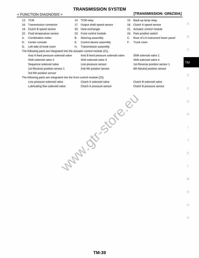
13. TCM 14. TCM relay 15. Back-up lamp relay
16. Transmission connector 17. Output shaft speed sensor 18. Clutch A speed sensor
19. Clutch B speed sensor 20. Heat exchanger 21. Actuator control module
22. Fluid temperature sensor 23. Front control module 24. Park position switch
A. Combination meter B. Steering assembly C. Rear of LH instrument lower panel
D. Center console E. Control device assembly F. Trunk room
G. Left side of trunk room H. Transmission assembly
The following parts are integrated into the actuator control module (21).
Axis A feed pressure solenoid valve Axis B feed pressure solenoid valve Shift solenoid valve 1
Shift solenoid valve 2 Shift solenoid valve 3 Shift solenoid valve 4
Sequence solenoid valve Line pressure sensor 1st-Reverse position sensor 1
1st-Reverse position sensor 1 2nd-4th position sensor 6th-Neutral position sensor
3rd-5th position sensor
The following parts are integrated into the front control module (23).
Line pressure solenoid valve Clutch A solenoid valve Clutch B solenoid valve
Lubricating flow solenoid valve Clutch A pressure sensor Clutch B pressure sensor
www.gtr-
store
.eu
TM-39

[TRANSMISSION: GR6Z30A]ON BOARD DIAGNOSTIC (OBD) SYSTEM
< FUNCTION DIAGNOSIS >
ON BOARD DIAGNOSTIC (OBD) SYSTEM
Diagnosis Description (GT-R certified NISSAN dealer) INFOID:0000000004019831
Refer to XX-XX, "*****".
www.gtr-
store
.eu
TM-40

DIAGNOSIS SYSTEM (TCM)[TRANSMISSION: GR6Z30A]
C
E
F
G
H
I
J
K
L
M
A
B
M
N
O
P
< FUNCTION DIAGNOSIS >
T
DIAGNOSIS SYSTEM (TCM)
CONSULT-III Function (GT-R certified NISSAN dealer) INFOID:0000000004019832
FUNCTION
SELF DIAGNOSTIC RESULTRefer to TM-233, "DTC Index".
DATA MONITOR
Display Item List
X: Standard, –: Not applicable, : Option
Items Function
Ecu Identification Displays control unit part number or identification number.
Self Diagnostic Result Receives self-diagnosis results from control unit and displays DTCs.
Data Monitor Receives, displays and records the input/output signals from control unit.
Active Test Transmits commands to control unit to change output signals and check operation of output system.
Work support Adjusts the components or systems quickly and exactly.
Configuration Writes the data such as vehicle specification information to control unit.
CAN DIAG SUPPORT MNTR Displays the communication status of CAN.
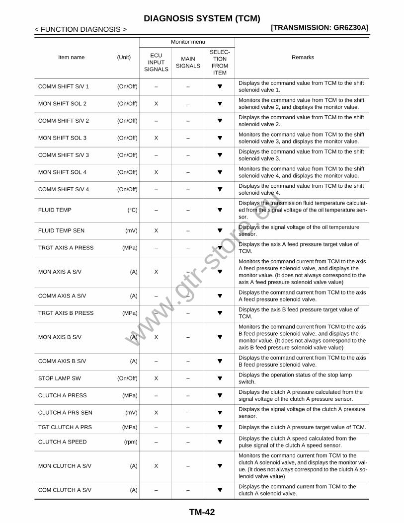
Item name (Unit)
Monitor menu
RemarksECUINPUT
SIGNALS
MAINSIGNALS
SELEC-TION FROM ITEM
SLEEVE B1 POSI 1 (mm or in.) – XDisplays the sleeve B1 position calculated from the signal voltage of the 1st-Reverse position sensor 1.
SLEEVE B1 POSI 2 (mm or in.) – XDisplays the sleeve B1 position calculated from the signal voltage of the 1st-Reverse position sensor 2.
1-R POSITION SEN 1 (mV) X –Displays the signal voltage of the 1st-Reverse posi-tion sensor 1.
1-R POSITION SEN 2 (mV) X –Displays the signal voltage of the 1st-Reverse posi-tion sensor 2.
SLEEVE A2 POSI (mm or in.) – XDisplays the sleeve A2 position calculated from the signal voltage of the 2nd-4th position sensor.
2-4 POSITION SEN (mV) X –Displays the signal voltage of the 2nd-4th position sensor.
SLEEVE B2 POSI (mm or in.) – XDisplays the sleeve B2 position calculated from the signal voltage of the 3rd-5th position sensor.
3-5 POSITION SEN (mV) X –Displays the signal voltage of the 3rd-5th position sensor.
SLEEVE A1 POSI (mm or in.) – XDisplays the sleeve A1 position calculated from the signal voltage of the 6th-Neutral position sensor.
6-N POSITION SEN (mV) X –Displays the signal voltage of the 6th-Neutral posi-tion sensor.
ABS OPERATION SIG (On/Off) X –Displays the ABS operation signal received from ABS actuator and electric unit (control unit) via CAN communication.
ACCEL POSI SEN 1 (0.0/8) X –Displays the accelerator pedal position signal re-ceived from ECM via CAN communication.
MON SHIFT SOL 1 (On/Off) X –Monitors the command value from TCM to the shift solenoid valve 1, and displays the monitor value.
www.gtr-
store
.eu
TM-41
[TRANSMISSION: GR6Z30A]DIAGNOSIS SYSTEM (TCM)
< FUNCTION DIAGNOSIS >
COMM SHIFT S/V 1 (On/Off) – –Displays the command value from TCM to the shift solenoid valve 1.
MON SHIFT SOL 2 (On/Off) X –Monitors the command value from TCM to the shift solenoid valve 2, and displays the monitor value.
COMM SHIFT S/V 2 (On/Off) – –Displays the command value from TCM to the shift solenoid valve 2.
MON SHIFT SOL 3 (On/Off) X –Monitors the command value from TCM to the shift solenoid valve 3, and displays the monitor value.
COMM SHIFT S/V 3 (On/Off) – –Displays the command value from TCM to the shift solenoid valve 3.
MON SHIFT SOL 4 (On/Off) X –Monitors the command value from TCM to the shift solenoid valve 4, and displays the monitor value.
COMM SHIFT S/V 4 (On/Off) – –Displays the command value from TCM to the shift solenoid valve 4.
FLUID TEMP (°C) – –Displays the transmission fluid temperature calculat-ed from the signal voltage of the oil temperature sen-sor.
FLUID TEMP SEN (mV) X –Displays the signal voltage of the oil temperature sensor.
TRGT AXIS A PRESS (MPa) – –Displays the axis A feed pressure target value of TCM.
MON AXIS A S/V (A) X –
Monitors the command current from TCM to the axis A feed pressure solenoid valve, and displays the monitor value. (It does not always correspond to the axis A feed pressure solenoid valve value)
COMM AXIS A S/V (A) – –Displays the command current from TCM to the axis A feed pressure solenoid valve.
TRGT AXIS B PRESS (MPa) – –Displays the axis B feed pressure target value of TCM.
MON AXIS B S/V (A) X –
Monitors the command current from TCM to the axis B feed pressure solenoid valve, and displays the monitor value. (It does not always correspond to the axis B feed pressure solenoid valve value)
COMM AXIS B S/V (A) – –Displays the command current from TCM to the axis B feed pressure solenoid valve.
STOP LAMP SW (On/Off) X –Displays the operation status of the stop lamp switch.
CLUTCH A PRESS (MPa) – –Displays the clutch A pressure calculated from the signal voltage of the clutch A pressure sensor.
CLUTCH A PRS SEN (mV) X –Displays the signal voltage of the clutch A pressure sensor.
TGT CLUTCH A PRS (MPa) – – Displays the clutch A pressure target value of TCM.
CLUTCH A SPEED (rpm) – –Displays the clutch A speed calculated from the pulse signal of the clutch A speed sensor.
MON CLUTCH A S/V (A) X –
Monitors the command current from TCM to the clutch A solenoid valve, and displays the monitor val-ue. (It does not always correspond to the clutch A so-lenoid valve value)
COM CLUTCH A S/V (A) – –Displays the command current from TCM to the clutch A solenoid valve.
Item name (Unit)
Monitor menu
RemarksECUINPUT
SIGNALS
MAINSIGNALS
SELEC-TION
FROM ITEM
www.gtr-
store
.eu
TM-42

DIAGNOSIS SYSTEM (TCM)[TRANSMISSION: GR6Z30A]
C
E
F
G
H
I
J
K
L
M
A
B
M
N
O
P
< FUNCTION DIAGNOSIS >
T
CLUTCH A TEMP (°C) – –Displays the estimated clutch A temperature calcu-lated by TCM.
CLUTCH B PRESS (MPa) – –Displays the clutch B pressure calculated from the signal voltage of the clutch B pressure sensor.
CLUTCH B PRS SEN (mV) X –Displays the signal voltage of the clutch B pressure sensor.
TGT CUTCH B PRES (MPa) – – Displays the clutch B pressure target value of TCM.
CLUTCH B SPEED (rpm) – –Displays the clutch B speed calculated from the pulse signal of the clutch B speed sensor.
MON CLUTCH B S/V (A) X –
Monitors the command current from TCM to the clutch B solenoid valve, and displays the monitor val-ue. (It does not always correspond to the clutch B so-lenoid valve value)
COM CLUTCH B S/V (A) – –Displays the command current from TCM to the clutch B solenoid valve.
CLUTCH B TEMP (°C) – –Displays the estimated clutch B temperature calcu-lated by TCM.
GR POSITION – –Displays the transmission gear positions recognized by TCM.
ENGINE SPEED (rpm) X XDisplays the engine speed signal received from ECM via CAN communication.
GR POSI INDICATION – XDisplays the transmission gear positions recognized by TCM.
IGN SW (On/Off) X – Displays the operation status of the ignition switch.
LINE PRESSURE (MPa) – –Displays the line pressure value calculated from the signal voltage of the line pressure sensor.
LINE PRESS SENSOR (mV) X –Displays the signal voltage of the line pressure sen-sor.
TRGT LINE PRESS (MPa) – – Displays the line pressure target value of TCM.
MON LINE PRES S/V (A) X –
Monitors the command current from TCM to the line pressure solenoid valve, and displays the monitor value. (It does not always correspond to the line pressure solenoid valve value)
COM LINE PRES S/V (A) – –Displays the command current from TCM to the line pressure solenoid valve.
TRGT LUBE PRESS (MPa) – – Displays the lubricating flow target value of TCM.
MON LUBE S/V (A) X –
Monitors the command current from TCM to the lu-bricating flow solenoid valve, and displays the moni-tor value. (It does not always correspond to the lubricating flow solenoid valve value)
COMM LUBE S/V (A) – –Displays the command current from TCM to the lubri-cating flow solenoid valve.
AM RANGE CHG SW 1 (On/Off) X –Displays the operation status of the Auto/Manual range change switch 1.
AM RANGE CHG SW 2 (On/Off) X –Displays the operation status of the Auto/Manual range change switch 2.
MODE – XDisplays the set-up switch (transmission) and driving range statuses.
Item name (Unit)
Monitor menu
RemarksECUINPUT
SIGNALS
MAINSIGNALS
SELEC-TION FROM ITEM
www.gtr-
store
.eu
TM-43
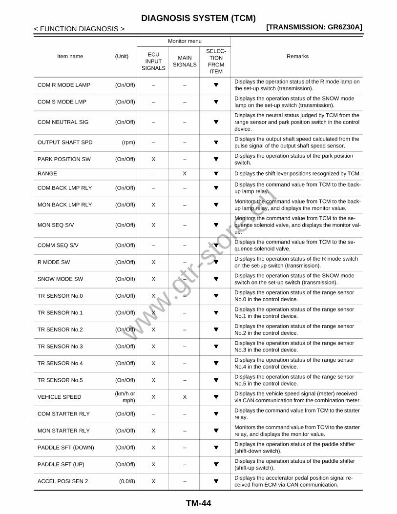
[TRANSMISSION: GR6Z30A]DIAGNOSIS SYSTEM (TCM)
< FUNCTION DIAGNOSIS >
COM R MODE LAMP (On/Off) – –Displays the operation status of the R mode lamp on the set-up switch (transmission).
COM S MODE LMP (On/Off) – –Displays the operation status of the SNOW mode lamp on the set-up switch (transmission).
COM NEUTRAL SIG (On/Off) – –Displays the neutral status judged by TCM from the range sensor and park position switch in the control device.
OUTPUT SHAFT SPD (rpm) – –Displays the output shaft speed calculated from the pulse signal of the output shaft speed sensor.
PARK POSITION SW (On/Off) X –Displays the operation status of the park position switch.
RANGE – X Displays the shift lever positions recognized by TCM.
COM BACK LMP RLY (On/Off) – –Displays the command value from TCM to the back-up lamp relay.
MON BACK LMP RLY (On/Off) X –Monitors the command value from TCM to the back-up lamp relay, and displays the monitor value.
MON SEQ S/V (On/Off) X –Monitors the command value from TCM to the se-quence solenoid valve, and displays the monitor val-ue.
COMM SEQ S/V (On/Off) – –Displays the command value from TCM to the se-quence solenoid valve.
R MODE SW (On/Off) X –Displays the operation status of the R mode switch on the set-up switch (transmission).
SNOW MODE SW (On/Off) X –Displays the operation status of the SNOW mode switch on the set-up switch (transmission).
TR SENSOR No.0 (On/Off) X –Displays the operation status of the range sensor No.0 in the control device.
TR SENSOR No.1 (On/Off) X –Displays the operation status of the range sensor No.1 in the control device.
TR SENSOR No.2 (On/Off) X –Displays the operation status of the range sensor No.2 in the control device.
TR SENSOR No.3 (On/Off) X –Displays the operation status of the range sensor No.3 in the control device.
TR SENSOR No.4 (On/Off) X –Displays the operation status of the range sensor No.4 in the control device.
TR SENSOR No.5 (On/Off) X –Displays the operation status of the range sensor No.5 in the control device.
VEHICLE SPEED(km/h or
mph)X X
Displays the vehicle speed signal (meter) received via CAN communication from the combination meter.
COM STARTER RLY (On/Off) – –Displays the command value from TCM to the starter relay.
MON STARTER RLY (On/Off) X –Monitors the command value from TCM to the starter relay, and displays the monitor value.
PADDLE SFT (DOWN) (On/Off) X –Displays the operation status of the paddle shifter (shift-down switch).
PADDLE SFT (UP) (On/Off) X –Displays the operation status of the paddle shifter (shift-up switch).
ACCEL POSI SEN 2 (0.0/8) X –Displays the accelerator pedal position signal re-ceived from ECM via CAN communication.
Item name (Unit)
Monitor menu
RemarksECUINPUT
SIGNALS
MAINSIGNALS
SELEC-TION
FROM ITEM
www.gtr-
store
.eu
TM-44

DIAGNOSIS SYSTEM (TCM)[TRANSMISSION: GR6Z30A]
C
E
F
G
H
I
J
K
L
M
A
B
M
N
O
P
< FUNCTION DIAGNOSIS >
T
ACTIVE TEST
Procedure
1. Apply parking brake.2. Shift the shift lever to the P position.
CAUTION:Check that the park lock operates.
3. Start the engine.4. Select the operation item.
NOTE:• Operable only in the P position, and inoperable in other positions.• Only one item is operable, and multiple items cannot be operated at the same time.
Test item list
WORK SUPPORT
BATTERY VOLTAGE (V) X X Displays the power supply voltage of TCM.
VDC OPERATION SIG (On/Off) X –Displays the VDC operation signal received from ABS actuator and electric unit (control unit) via CAN communication.
TCM RELAY (On/Off) – – Displays the operation status of the TCM relay.
SHIFT LOCK SOL (On/Off) – –Displays the operation status of the shift lock sole-noid.
Item name (Unit)
Monitor menu
RemarksECUINPUT
SIGNALS
MAINSIGNALS
SELEC-TION FROM ITEM
Items Function check
SHIFT S/V 1In response to the ON/OFF command from CONSULT-III, TCM supplies the current to the sole-noid valve to enable an operation check of the solenoid valve.CAUTION:If the solenoid valve has a malfunction such as sticking, it does not operate. Check for operation noise or vibrations.
SHIFT S/V 2
SHIFT S/V 3
SHIFT S/V 4
SEQUENCE S/V
LINE PRESS S/VIn response to the pressure indication value from CONSULT-III, TCM supplies the current to the solenoid valve to enable an operation check of the solenoid valve.CAUTION:If the solenoid valve has a malfunction such as sticking, it does not operate. Check using Data Monitor.NOTE:Controls so that the oil pressure is built up in each solenoid valve.
C/L B PRESS S/V
C/L A PRESS S/V
LUBRICATION FLOW-RATE S/V
A-AXIS SUPPLY PRESSURE S/V
B-AXIS SUPPLY PRESSURE S/V
STARTER RELAY In response to the ON/OFF command from CONSULT-III, TCM supplies the current to the relay to enable an operation check of the relay.CAUTION:If the relay has a malfunction such as sticking, it does not operate. Check for an operation noise or vibrations.
REVERSE LAMP RELAY
TCM RELAY
SHIFT LOCK SOLENOID
In response to the ON/OFF command from CONSULT-III, TCM supplies the current to the shift lock solenoid to enable an operation check of the shift lock solenoid.CAUTION:If the solenoid has a malfunction such as sticking, it does not operate. Check for an oper-ation noise or vibrations.NOTE:With the engine running and the brake pedal depressed, check that the shift lever can be moved from the P position in accordance with the ON/OFF operation.
www.gtr-
store
.eu
TM-45

[TRANSMISSION: GR6Z30A]DIAGNOSIS SYSTEM (TCM)
< FUNCTION DIAGNOSIS >
トランスミッション現象別作業フローFollowing the work order descrived below enables the adjustment of an appropriate transmission condition.Work order depends on vehicle conditions.
Item
Maintenance
Periodic inspectionReplacement of transmission
assembly
Work item
Check symptom 1
CONSULT-III function(TRANSMIS-SION)
CLUTCH GEAR LEARNING 3 3
WRITE PREVIOUS CLUTCH LEARNING VALUE
• DELETE GEAR POSITION LEARNING VALUE
• DELETE CLUTCH A LEARNING VALUE• DELETE CLUTCH A LEARNING VALUE• ERASE CLUTCH ENGGMNTPRSSR
CRRCTN
1
ADJUST CLUTCH A CAPACITY
Clutch capacity up.
Clutch capacity down.
Set clutch capacity to 0. 2 2
ADJUST CLUTCH B CAPACITY
Clutch capacity up.
Clutch capacity down.
Set clutch capacity to 0. 2 2
CLUTCH A TOUCH POINT
Move the clutch touch point closer.
Move the clutch touch point farther.
Set Clutch touch point to 0. 2 2
CLUTCH B TOUCH POINT
Move the clutch touch point closer.
Move the clutch touch point farther.
Set Clutch touch point to 0. 2 2
CONSULT-III function(ENGINE)
IDLE AIR VOL LEARN
Traveling check 4 4
Traveling check by customer 5 5
Remarks
Clutch clearance returns to an optimum value because “CLUTCH GEAR LEARNING” is simultaneously performed within “CLUTCH TOUCH POINT LEARNING”. There-fore, gear feeling and creep strength may change.
—
www.gtr-
store
.eu
TM-46

DIAGNOSIS SYSTEM (TCM)[TRANSMISSION: GR6Z30A]
C
E
F
G
H
I
J
K
L
M
A
B
M
N
O
P
< FUNCTION DIAGNOSIS >
T
www.gtr-
store
.eu
TM-47
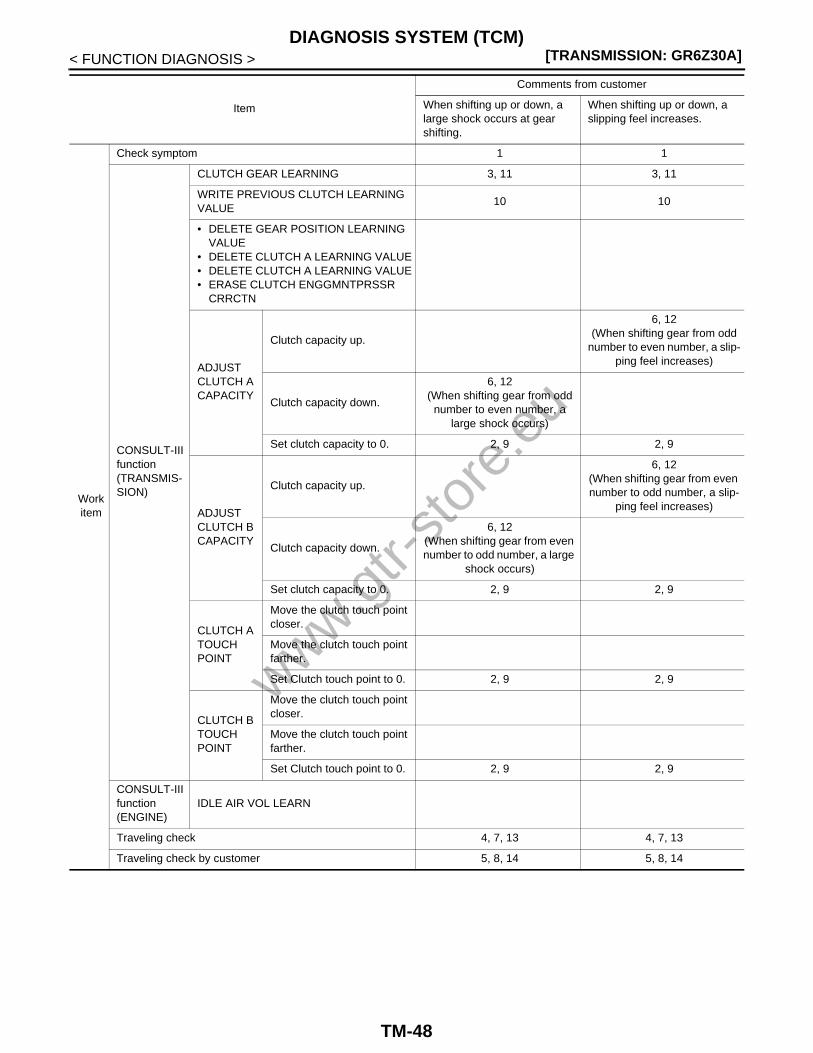
[TRANSMISSION: GR6Z30A]DIAGNOSIS SYSTEM (TCM)
< FUNCTION DIAGNOSIS >
Item
Comments from customer
When shifting up or down, a large shock occurs at gear shifting.
When shifting up or down, a slipping feel increases.
Work item
Check symptom 1 1
CONSULT-III function(TRANSMIS-SION)
CLUTCH GEAR LEARNING 3, 11 3, 11
WRITE PREVIOUS CLUTCH LEARNING VALUE
10 10
• DELETE GEAR POSITION LEARNING VALUE
• DELETE CLUTCH A LEARNING VALUE• DELETE CLUTCH A LEARNING VALUE• ERASE CLUTCH ENGGMNTPRSSR
CRRCTN
ADJUST CLUTCH A CAPACITY
Clutch capacity up.
6, 12(When shifting gear from odd
number to even number, a slip-ping feel increases)
Clutch capacity down.
6, 12(When shifting gear from odd
number to even number, a large shock occurs)
Set clutch capacity to 0. 2, 9 2, 9
ADJUST CLUTCH B CAPACITY
Clutch capacity up.
6, 12(When shifting gear from even number to odd number, a slip-
ping feel increases)
Clutch capacity down.
6, 12(When shifting gear from even number to odd number, a large
shock occurs)
Set clutch capacity to 0. 2, 9 2, 9
CLUTCH A TOUCH POINT
Move the clutch touch point closer.
Move the clutch touch point farther.
Set Clutch touch point to 0. 2, 9 2, 9
CLUTCH B TOUCH POINT
Move the clutch touch point closer.
Move the clutch touch point farther.
Set Clutch touch point to 0. 2, 9 2, 9
CONSULT-III function(ENGINE)
IDLE AIR VOL LEARN
Traveling check 4, 7, 13 4, 7, 13
Traveling check by customer 5, 8, 14 5, 8, 14
www.gtr-
store
.eu
TM-48

DIAGNOSIS SYSTEM (TCM)[TRANSMISSION: GR6Z30A]
C
E
F
G
H
I
J
K
L
M
A
B
M
N
O
P
< FUNCTION DIAGNOSIS >
TRemarks
• Clutch clearance returns to an optimum value because “CLUTCH GEAR LEARN-ING” is simultaneously per-formed within “CLUTCH TOUCH POINT LEARN-ING”. Therefore, gear feeling and creep strength may change.
• When lowering the clutch ca-pacity too much, a slipping feel may occur when starting the vehicle or shifting gears.
• Clutch clearance returns to an optimum value because “CLUTCH GEAR LEARN-ING” is simultaneously per-formed within “CLUTCH TOUCH POINT LEARN-ING”. Therefore, gear feel-ing and creep strength may change.
• When increasing the clutch capacity too much, a shock may increase by shifting gears.
Item
Comments from customer
When shifting up or down, a large shock occurs at gear shifting.
When shifting up or down, a slipping feel increases.
www.gtr-
store
.eu
TM-49

[TRANSMISSION: GR6Z30A]DIAGNOSIS SYSTEM (TCM)
< FUNCTION DIAGNOSIS >
Item
Comments from customer
When starting the vehicle, a large shock occurs or the en-
gine revolutions blow up.
When starting the vehicle, a slipping feel increases.
Work item
Check symptom 1 1
CONSULT-III function(TRANSMIS-SION)
CLUTCH GEAR LEARNING 3, 11 3, 11
WRITE PREVIOUS CLUTCH LEARNING VALUE
10 10
• DELETE GEAR POSITION LEARNING VALUE
• DELETE CLUTCH A LEARNING VALUE• DELETE CLUTCH A LEARNING VALUE• ERASE CLUTCH ENGGMNTPRSSR
CRRCTN
ADJUST CLUTCH A CAPACITY
Clutch capacity up.
6, 12(When starting the vehicle
with 2nd gear, a slipping feel increases)
Clutch capacity down.
Set clutch capacity to 0. 2, 9 2, 9
ADJUST CLUTCH B CAPACITY
Clutch capacity up.
6, 12(When starting the vehicle
with 1st gear, a slipping feel increases)
Clutch capacity down.
Set clutch capacity to 0. 2, 9 2, 9
CLUTCH A TOUCH POINT
Move the clutch touch point closer.
6, 12(Occurrence of starting the vehi-
cle with 2nd gear)
Move the clutch touch point farther.
Set Clutch touch point to 0. 2, 9 2, 9
CLUTCH B TOUCH POINT
Move the clutch touch point closer.
6, 12(Occurrence of starting the vehi-
cle with 1st gear)
Move the clutch touch point farther.
Set Clutch touch point to 0. 2, 9 2, 9
CONSULT-III function(ENGINE)
IDLE AIR VOL LEARN
Traveling check 4, 7, 13 4, 7, 13
Traveling check by customer 5, 8, 14 5, 8, 14
Remarks
• Clutch clearance returns to an optimum value because “CLUTCH GEAR LEARN-ING” is simultaneously per-formed within “CLUTCH TOUCH POINT LEARNING”. Therefore, gear feeling and creep strength may change.
• When narrowing clearance too much, “Excessive creep” or “Low engine rev when op-erating select lever or paddle shifter” may occur.
• Clutch clearance returns to an optimum value because “CLUTCH GEAR LEARN-ING” is simultaneously per-formed within “CLUTCH TOUCH POINT LEARN-ING”. Therefore, gear feel-ing and creep strength may change.
• When increasing the clutch capacity too much, a shock may increase by shifting gears.
www.gtr-
store
.eu
TM-50

DIAGNOSIS SYSTEM (TCM)[TRANSMISSION: GR6Z30A]
C
E
F
G
H
I
J
K
L
M
A
B
M
N
O
P
< FUNCTION DIAGNOSIS >
T
ItemComments from customer
When starting the vehicle, creep strength increases.
Work item
Check symptom 1
CONSULT-III function(TRANSMIS-SION)
CLUTCH GEAR LEARNING 3, 11
WRITE PREVIOUS CLUTCH LEARNING VALUE
• DELETE GEAR POSITION LEARNING VALUE
• DELETE CLUTCH A LEARNING VALUE• DELETE CLUTCH A LEARNING VALUE• ERASE CLUTCH ENGGMNTPRSSR
CRRCTN
ADJUST CLUTCH A CAPACITY
Clutch capacity up.
Clutch capacity down.
Set clutch capacity to 0. 2
ADJUST CLUTCH B CAPACITY
Clutch capacity up.
Clutch capacity down.
Set clutch capacity to 0. 2
CLUTCH A TOUCH POINT
Move the clutch touch point closer.
Move the clutch touch point farther.
7(When starting the vehicle with 2nd gear, creep strength increas-
es)
Set Clutch touch point to 0. 2
CLUTCH B TOUCH POINT
Move the clutch touch point closer.
Move the clutch touch point farther.
7(When starting the vehicle with 1st gear, creep strength increas-
es.)
Set Clutch touch point to 0. 2
CONSULT-III function(ENGINE)
IDLE AIR VOL LEARN 4
Traveling check 5, 8
Traveling check by customer 6, 9
Remarks
• Clutch clearance returns to an optimum value because “CLUTCH GEAR LEARNING” is simultaneously performed within “CLUTCH TOUCH POINT LEARNING”. Therefore, gear feeling and creep strength may change.
• When widening the clutch clearance too much, “Engine rev blowup at startup” or “Large shock at startup” may occur.
www.gtr-
store
.eu
TM-51

[TRANSMISSION: GR6Z30A]DIAGNOSIS SYSTEM (TCM)
< FUNCTION DIAGNOSIS >
Item
Comments from customer
When shifting the selector lever from P/N to A/R, a large shock occurs.
• When shifting the selector lever from P/N to A/R, en-gine revolutions decreases.
• When shifting from M1 to M2 with the paddle shifter, engine revolutions decreas-es.
Work item
Check symptom 1 1
CONSULT-III function(TRANSMIS-SION)
CLUTCH GEAR LEARNING 3 3
WRITE PREVIOUS CLUTCH LEARNING VALUE
• DELETE GEAR POSITION LEARNING VALUE
• DELETE CLUTCH A LEARNING VALUE• DELETE CLUTCH A LEARNING VALUE• ERASE CLUTCH ENGGMNTPRSSR
CRRCTN
ADJUST CLUTCH A CAPACITY
Clutch capacity up.
Clutch capacity down.
Set clutch capacity to 0. 2 2
ADJUST CLUTCH B CAPACITY
Clutch capacity up.
Clutch capacity down.
Set clutch capacity to 0. 2 2
CLUTCH A TOUCH POINT
Move the clutch touch point closer.
Move the clutch touch point farther.
7(When shifting to M2)
Set Clutch touch point to 0. 2 2
CLUTCH B TOUCH POINT
Move the clutch touch point closer.
Move the clutch touch point farther.
7(When shifting to A, M1 or R)
Set Clutch touch point to 0. 2 2
CONSULT-III function(ENGINE)
IDLE AIR VOL LEARN 4
Traveling check 4 5, 8
Traveling check by customer 5 6, 9
Remarks
Clutch clearance returns to an optimum value because “CLUTCH GEAR LEARNING” is simultaneously performed within “CLUTCH TOUCH POINT LEARNING”. Therefore, gear feeling and creep strength may change.
• Clutch clearance returns to an optimum value because “CLUTCH GEAR LEARN-ING” is simultaneously per-formed within “CLUTCH TOUCH POINT LEARN-ING”. Therefore, gear feel-ing and creep strength may change.
• When widening the clutch clearance to much, “Engine rev blowup at startup” or “Large shock at startup” may occur.
www.gtr-
store
.eu
TM-52

DIAGNOSIS SYSTEM (TCM)[TRANSMISSION: GR6Z30A]
C
E
F
G
H
I
J
K
L
M
A
B
M
N
O
P
< FUNCTION DIAGNOSIS >
T
Procedure
1. Apply parking brake.2. Shift the shift lever to the P position.
CAUTION:Check that the park lock operates.
3. Start the engine.NOTE:The operation is available only after the ignition switch is turned ON, except for the “CLUTCH GEARLEARNING”, “GEAR POSITION TEST”, and “DISENGAGING THE GEAR”.
Item
Comments from customer
• While driving, an abnormal noise and a shock occur when de-pressing the brake pedal to reduce speed and shifting down from the 3rd to the 2nd.
• While driving with the 2nd gear, the driving force at around idle becomes large.
Work item
Check symptom 1
CONSULT-III function(TRANSMIS-SION)
CLUTCH GEAR LEARNING 3
WRITE PREVIOUS CLUTCH LEARNING VALUE
• DELETE GEAR POSITION LEARNING VALUE
• DELETE CLUTCH A LEARNING VALUE• DELETE CLUTCH A LEARNING VALUE• ERASE CLUTCH ENGGMNTPRSSR
CRRCTN
ADJUST CLUTCH A CAPACITY
Clutch capacity up.
Clutch capacity down.
Set clutch capacity to 0. 2
ADJUST CLUTCH B CAPACITY
Clutch capacity up.
Clutch capacity down.
Set clutch capacity to 0. 2
CLUTCH A TOUCH POINT
Move the clutch touch point closer.
Move the clutch touch point farther.
7
Set Clutch touch point to 0. 2
CLUTCH B TOUCH POINT
Move the clutch touch point closer.
Move the clutch touch point farther.
Set Clutch touch point to 0. 2
CONSULT-III function(ENGINE)
IDLE AIR VOL LEARN 4
Traveling check 5, 8
Traveling check by customer 6, 9
Remarks
• Clutch clearance returns to an optimum value because “CLUTCH GEAR LEARNING” is simultaneously performed within “CLUTCH TOUCH POINT LEARNING”. Therefore, gear feeling and creep strength may change.
• When widening the clutch clearance too much, “Engine rev blowup at startup with 2nd gear” or “Large shock at startup with 2nd gear” may occur.
www.gtr-
store
.eu
TM-53

[TRANSMISSION: GR6Z30A]DIAGNOSIS SYSTEM (TCM)
< FUNCTION DIAGNOSIS >4. Select the operation item.
NOTE:• Operable only in the P position, and inoperable in other positions.• Only one item is operable, and multiple items cannot be operated at the same time.
Display Item List
Items Function or item Application
CLUTCH GEAR LEARNING
Perform the learning of the clutch touch point and the engaged gear position and neutral position for each gear.CAUTION:• Clutch gear learning can only be performed once in one
driving cycle (the ignition switch OFF→ON→OFF).• If no clutch gear learning can be performed, it is neces-
sary to turn the ignition switch OFF→ON, and perform the clutch gear learning again.
Always perform this procedure during maintenance and when TCM or transmission is replaced.
READ CLUTCH GEAR LEARN-ING DATA
Check the clutch gear learning status.CAUTION:Except for learning experience check, after the learning, when the ignition switch is turned OFF, no more checks can be performed.
After the clutch gear learning, a check that the learning is com-pleted normally can be per-formed.
GEAR POSITION TEST Allows engagement of each gear individually.The operation of each gear can be checked.
DISENGAGING THE GEAR Allows making all the gears neutral.Use when returning the gear to neutral.
ADJUST CLUTCH B CAPACITYAllows adjustment of the clutch capacity in 15 stages.
• 0: Initial• 1 – 7: Clutch capacity up• −1 – −7: Clutch capacity
down
If a shock or slip is large during gear shift and start-up, adjust the clutch capacity.ADJUST CLUTCH A CAPACITY
CLUTCH A TOUCH POINT
Allows adjustment of the clutch touch point in 15 stages.
• 0: Initial• 1 – 7: Move the clutch touch
point closer.• −1 – −7: Moves the clutch
touch point farther.
In the event of a strong creep power, poor start-up response, or excess start-up shock, adjusts the clutch touch point.
CLUTCH B TOUCH POINT
WRITE PREVIOUS CLUTCH LEARNING VALUE
The clutch touch point learning value can be returned to the pre-vious learning value.
Used when the clutch learning value is returned to the previous learning value upon the request from a customer (when the cus-tomer prefers the previous set-ting than the current learned driving feeling, for example).
DELETE GEAR POSITION LEARNING VALUE
The gear position learning value can be erased and returned to the initial value.
Always erase the previous trans-mission learning value, when the
transmission is replaced.*1
DELETE CLUTCH A LEARNING VALUE
The clutch A learning value can be erased and returned to the initial value.CAUTION:If the clutch learning values is erased at a time other than a transmission replacement, the previous learning values can no longer be resumed.
DELETE CLUTCH B LEARNING VALUE
The clutch B learning value can be erased and returned to the initial value.CAUTION:If the clutch learning values is erased at a time other than a transmission replacement, the previous learning values can no longer be resumed.
ERASE CLTCH ENGGMNT PRSSR CRRCTN
The clutch engagement pressure correction value can be erased and returned to the initial value.CAUTION:If only TCM is replaced, since a new TCM has no memory of the clutch engagement pressure correction value, it may require the clutch A/B capacity adjustment.
www.gtr-
store
.eu
TM-54

DIAGNOSIS SYSTEM (TCM)[TRANSMISSION: GR6Z30A]
C
E
F
G
H
I
J
K
L
M
A
B
M
N
O
P
< FUNCTION DIAGNOSIS >
T• *1: If the learning value is erased, the transmission warning light blinks.
• *2: Refer to the “Clutch protection history”.
• *3: Refer to the “Clutch overheat protection history”.
• *4: Refer to the "Line pressure loss history".
• *5: Refer to the "High oil temperature Protection History".
Clutch protection history• If the clutch temperature increases abnormally, the activation of protection control can be checked. In addi-
tion, because the protection control consists of a few stages, the history is displayed in each stage.
*1: It is judged as the “stall driving conditions”, if the following conditions are met. Acceleration pedal position: Approx. 0.6/8 or more,vehicle speed: Approx. 3 km/h (1 MPH) or less
Clutch overheat protection history• Shows the operation history of the clutch overheating protection control due to stall driving. Refer to the
“Clutch protection”.
Line pressure loss history• Shows the history of abnormal drop of the line pressure. [The line pressure sensor value is 0.2 MPa (2.04
kg/cm2, 29 psi) or less]NOTE:The possible causes for line pressure drop are as follows.• Fluid level drop due to oil leakage• Poor fluid suction due to deformation of the oil pan or others
High oil temperature protection history• If the transmission fluid temperature increases abnormally, the activation of protection control can be
checked. In addition, because the protection control consists of a few stages, the history is displayed in eachstage.
SHOW OIL TEMP HISTORYThe transmission fluid temperature frequency can be confirmed in 5 stages, providing the information of the temperature range used.
By checking the proportion of the count in each range, it can be used as information to judge whether hard driving occurs.
HIGH OIL TEMP WARNING HISTORY
• Clutch A Protection 1, 2, 3, 4*2
• Clutch B Protection 1, 2, 3, 4*2
• Clutch Overheat Protection History 1*3
• Line Pressure Loss History*4
• High Oil Temp Protection History 1, 2, 3*5
Items Clutch protection 1 Clutch protection 2 Clutch protection 3 Clutch protection 4
Description
The transmission warn-ing lamp is illuminated and the message “T/M CLUTCH TEMP HIGH STOP VEHICLE UNTIL WARNING TURNS OFF” appears in the in-formation display.
Performs the engine torque restriction.
Lowers the upper limit of the engine torque re-striction.
Release the clutch.
Operation conditions (if either of them is met)
Clutch tem-perature conditions
Depending on the clutch temperature increase, the clutch protection control shifts from clutch protection 1 to 4.
Stall driving condi-
tions*1
Depending on the time from the start of stall driving, the clutch protection control shifts from clutch pro-tection 1 to 4.
Cancel conditions When the clutch temperature is lowered and the wide open throttle status continues for a certain period.
Warning light on Exists
Engine torque restriction Does not exist Exists
Items Function or item Application
www.gtr-
store
.eu
TM-55

[TRANSMISSION: GR6Z30A]DIAGNOSIS SYSTEM (TCM)
< FUNCTION DIAGNOSIS >
CAUTION:• During one driving cycle (ignition switch OFF → ON → OFF), if the “High Oil Temp Protection His-
tory 2” status is reached 3 times, after that the high oil temperature protection remains active.• When the ignition switch is turned OFF, the high oil temperature protection is deactivated.
CONFIGURATION
Procedure
1. Apply parking brake.2. Shift the shift lever to the P position.
CAUTION:Check that the park lock operates.
3. Turn the ignition switch ON.4. Select the operation item.
Display Item List
ItemsHigh oil temperature protection
history 1High oil temperature protection
history 2High oil temperature protection
history 3
Description
The transmission warning lamp is on and the message “T/M OIL TEMP HIGH DECREASE SPEED” appears in the informa-tion display.
Performs the engine torque re-striction and engine speed re-striction.
Lowers the upper limit of the en-gine torque restriction and engine speed restriction.
Operation contentsAs the oil temperature increases, the high oil protection control shifts from the high oil temperature pro-tection history 1 to 3.
Cancel conditionsWhen the oil temperature is lowered and the wide open throttle status continues for a certain period of time.
Warning light on Exists
Engine torque restriction, engine speed restriction
Does not exist Exists
Items Function Application
Write IP Chara
Writes the acquired IP characteristics data to TCM.• If the transmission is replaced: Write the IP
characteristics of replaced transmission to TCM that is not replaced.
• If TCM is replaced: Write the IP characteristics of transmission that is not replaced to replaced TCM.
• If both of them are replaced: Write the IP char-acteristics of replaced transmission to re-placed TCM.
CAUTION:• The “write IP characteristics” can only be
performed once in one driving cycle (the ignition switch OFF→ON→OFF).
• If the write IP characteristics cannot be per-formed, turn the ignition switch OFF→ON and perform the write IP characteristics again.
The individual variations of the transmission hy-draulic parts are read into TCM to stabilize the control.
Read IP Chara Written Data
Check the write IP characteristics status.CAUTION:Except for the write experience, nothing can be checked after the IP writing, if the ignition switch is turned OFF.
The write IP characteristics status can be checked when the write IP characteristics is completed or the writing is not successful.
www.gtr-
store
.eu
TM-56

U1000 CAN COMM CIRCUIT[TRANSMISSION: GR6Z30A]
C
E
F
G
H
I
J
K
L
M
A
B
M
N
O
P
< COMPONENT DIAGNOSIS >
T
COMPONENT DIAGNOSISU1000 CAN COMM CIRCUIT
Description (GT-R certified NISSAN dealer) INFOID:0000000004019833
CAN (Controller Area Network) is a serial communication line for real time application. It is an on-vehicle mul-tiplex communication line with high data communication speed and excellent malfunction detection ability.Many electronic control units are equipped onto a vehicle, and each control unit shares information and linkswith other control units during operation (not independent). In CAN communication, control unit is connectedwith 2 communication lines (CAN-H and CAN-L) allowing a high rate of information transmission with less wir-ing. Each control unit communicates data but selectively reads required data only.
DTC Logic (GT-R certified NISSAN dealer) INFOID:0000000004019834
DTC DETECTION LOGIC
DTC CONFIRMATION PROCEDURE
1.PRECONDITIONING
If another “DTC CONFIRMATION PROCEDURE” is performed just before the next test, turn the ignitionswitch OFF and wait for 10 seconds or more, then perform the next test.
>> GO TO 2.
2.CHECK DTC DETECTION
With CONSULT-III1. Start the engine and wait for 2 seconds or more.2. Check “Self Diagnostic Result” of “TRANSMISSION”.Is DTC detected?YES >> Go to TM-57, "Diagnosis Procedure (GT-R certified NISSAN dealer)".NO >> INSPECTION END
Diagnosis Procedure (GT-R certified NISSAN dealer) INFOID:0000000004019835
1.CHECK DTC WITH TRANSMISSION
With CONSULT-III1. Start the engine and wait for at least 2 seconds.2. Check “Self Diagnostic Result” of “TRANSMISSION”.Is DTC detected?YES >> Go to XX-XX, "*****".NO >> GO TO 2.
2.CHECK INTERMITTENT INCIDENT
Refer to XX-XX, "*****".
>> INSPECTION END
DTC Self-diagnosis name DTC detecting condition Possible cause
U1000 CAN communication lineWhen TCM is not transmitting or receiving CAN communication signal for 2 seconds or more.
Harness or connectors(CAN communication line is open or short-ed.)
www.gtr-
store
.eu
TM-57

[TRANSMISSION: GR6Z30A]P0700 TCM
< COMPONENT DIAGNOSIS >
P0700 TCM
Description (GT-R certified NISSAN dealer) INFOID:0000000004019836
• TCM consists of the microcomputer and input/output connectors for signal and power supply. • TCM controls the transmission by performing the following functions: power supply to the devices connected
to the transmission, operation control for each solenoid valve and actuator, data receiving from each sensor,receiving of signals from the range sensors, paddle shifter, auto/manual range change switch and communi-cation (CAN or hard wire) to C/U controlling other devices.
• TCM uses 3 different power supply routes to distribute power supply to each sensor.
DTC Logic (GT-R certified NISSAN dealer) INFOID:0000000004019837
DTC DETECTION LOGICCAUTION:• Before TCM is replaced, the IP characteristics must be extracted, based on the information read out
from the malfunctioning TCM. For reading out the IP characteristic data, refer to “CONSULT-III GT-RTCM CONFIGURATION MANUAL”.
• If no IP characteristic data can be extracted TCM and the transmission assembly must be replacedas a set.
*: A DTC is displayed when E, F, G or H in the DTC detection conditions is detected.
DTC CONFIRMATION PROCEDURE
1.PREPARATION BEFORE OPERATION
If another “DTC CONFIRMATION PROCEDURE” is performed just before the next test, turn the ignitionswitch OFF and wait for 10 seconds or more, then perform the next test.
Sensor power supply 1 Sensor power supply 2 Sensor power supply 3
• Output shaft speed sensor• Line pressure sensor
• Clutch A pressure sensor• Clutch A speed sensor• 6th-Neutral position sensor• 2nd-4th position sensor• Range sensor power supply 1 (Range
sensor No. 0, 1, 3, 5)
• Clutch B pressure sensor• Clutch B speed sensor• 1st-Reverse position sensor 1• 1st-Reverse position sensor 2• 3rd-5th position sensor• Range sensor power supply 2 (Range
sensor No. 2, 4)
DTC Self-diagnosis name DTC detection condition Possible cause
P0700
ECM receiving malfunction AA DTC is set if TCM cannot receive the CAN communication signals from ECM for 2 seconds or more.
• ECM• Harness or connector
(CAN communication line is open or short-ed)
Receiving of malfunctioning engine torque signal
BA DTC is set if abnormal engine torque signal is received from ECM.
ECMReceiving of malfunctioning engine speed signal
CA DTC is set if abnormal engine speed signal is received from ECM.
Sensor power supply voltage DA DTC is set if TCM detects DTC P0720 and DTC P0872.
• TCM• Harness or connector
(Open in the TCM ground circuit)
TCM internal*
EA DTC is set if TCM computing unit does not operate normally.
TCM
FA DTC is set if TCM monitor unit does not operate normally.
GA DTC is set if TCM function unit does not operate normally.
HA DTC is set if TCM self-shutoff does not operate normally.
www.gtr-
store
.eu
TM-58

P0700 TCM[TRANSMISSION: GR6Z30A]
C
E
F
G
H
I
J
K
L
M
A
B
M
N
O
P
< COMPONENT DIAGNOSIS >
T
>> GO TO 2.
2.PERFORM DTC CONFIRMATION PROCEDURE — DTC DETECTION CONDITION A, B
With CONSULT-IIIPerform “DTC CONFIRMATION PROCEDURE” for the engine DTCs U1000, P0605, P0102, P0103, P010C,and P010D.
Without CONSULT-IIIPerform “DTC CONFIRMATION PROCEDURE” for the engine DTCs U1000, P0605, P0102, P0103, P010C,and P010D.Is the DTC detected?YES >> Go to TM-60, "Diagnosis Procedure (GT-R certified NISSAN dealer)".NO >> GO TO 3.
3.PERFORM DTC CONFIRMATION PROCEDURE — DTC DETECTION CONDITION C
With CONSULT-III1. Start the engine.2. Check “Self Diagnostic Result” of “TRANSMISSION”.
Without CONSULT-III1. Start the engine.2. Check self-diagnosis.Is DTC P0700 detected?YES >> Go to TM-60, "Diagnosis Procedure (GT-R certified NISSAN dealer)".NO >> GO TO 4.
4.PERFORM DTC CONFIRMATION PROCEDURE — DTC DETECTION CONDITION D
With CONSULT-IIICheck “Self Diagnostic Result” of “TRANSMISSION”.
Without CONSULT-IIICheck self-diagnosis.Are DTCs P0700, P0720 and P0872 detected?YES >> Go to TM-60, "Diagnosis Procedure (GT-R certified NISSAN dealer)".NO >> GO TO 5.
5.PERFORM DTC CONFIRMATION PROCEDURE — DTC DETECTION CONDITION E
With CONSULT-III1. Turn ignition switch ON, and wait for 10 seconds or more.2. Check “Self Diagnostic Result” of “TRANSMISSION”.
Without CONSULT-III1. Turn ignition switch ON, and wait for 10 seconds or more.2. Check self-diagnosis.Is DTC P0700 detected?YES >> Go to TM-60, "Diagnosis Procedure (GT-R certified NISSAN dealer)".NO >> GO TO 6.
6.PERFORM DTC CONFIRMATION PROCEDURE — DTC DETECTION CONDITION F
With CONSULT-III1. Turn ignition switch ON, and wait for 1 second or more.2. Turn the ignition switch OFF and wait for 5 seconds or more, then turn it ON again.3. Repeat the procedure shown in 2 above 5 times.4. Check “Self Diagnostic Result” of “TRANSMISSION”.
Without CONSULT-III1. Turn ignition switch ON, and wait for 1 second or more.2. Turn the ignition switch OFF and wait for 5 seconds or more, then turn it ON again.3. Repeat the procedure shown in 2 above 5 times.4. Check self-diagnosis.Is DTC P0700 detected?YES >> Go to TM-60, "Diagnosis Procedure (GT-R certified NISSAN dealer)".
www.gtr-
store
.eu
TM-59

[TRANSMISSION: GR6Z30A]P0700 TCM
< COMPONENT DIAGNOSIS >NO >> GO TO 7.
7.PERFORM DTC CONFIRMATION PROCEDURE — DTC DETECTION CONDITION G
With CONSULT-III1. Shift the shift lever as per the following: P→R→N→A→M positions (Keep the shift lever for 5 seconds or
more at each position).2. Check “Self Diagnostic Result” of “TRANSMISSION”.
Without CONSULT-III1. Shift the shift lever as per the following: P→R→N→A→M positions (Keep the shift lever for 5 seconds or
more at each position).2. Check self-diagnosis.Is DTC P0700 detected?YES >> Go to TM-60, "Diagnosis Procedure (GT-R certified NISSAN dealer)".NO >> GO TO 8.
8.PERFORM DTC CONFIRMATION PROCEDURE — DTC DETECTION CONDITION H
With CONSULT-III1. Turn ignition switch OFF, and wait for 5 seconds or more.2. Turn the ignition switch ON and wait for 5 seconds or more, then turn it OFF again.3. Repeat the procedure shown in 2 above 32 times.4. Turn the ignition switch ON.5. Check “Self Diagnostic Result” of “TRANSMISSION”.
Without CONSULT-III1. Turn ignition switch OFF, and wait for 5 seconds or more.2. Turn the ignition switch ON and wait for 5 seconds or more, then turn it OFF again.3. Repeat the procedure shown in 2 above 32 times.4. Turn the ignition switch ON.5. Check self-diagnosis.Is DTC P0700 detected?YES >> Go to TM-60, "Diagnosis Procedure (GT-R certified NISSAN dealer)".NO >> INSPECTION END
Diagnosis Procedure (GT-R certified NISSAN dealer) INFOID:0000000004019838
1.CHECK CAN COMMUNICATION CIRCUIT
Refer to TM-57, "Diagnosis Procedure (GT-R certified NISSAN dealer)".Is the inspection result normal?YES >> GO TO 2.NO >> Repair or replace damaged parts.
2.CHECK DTC WITH ECM
With CONSULT-III1. Turn ignition switch ON.2. Check “Self Diagnostic Result” of “ENGINE”.Is DTC detected?YES >> Check DTC Detected Item. Refer to XX-XX, "*****".NO >> GO TO 3.
3.CHECK ENGINE SPEED
With CONSULT-III1. Start the engine.2. Select “ENGINE SPEED” in “Data Monitor”.Is the engine speed value 8191?YES >> Replace ECM.NO >> GO TO 4.
4.CHECK OUTPUT SHAFT SPEED SENSOR CIRCUIT
www.gtr-
store
.eu
TM-60
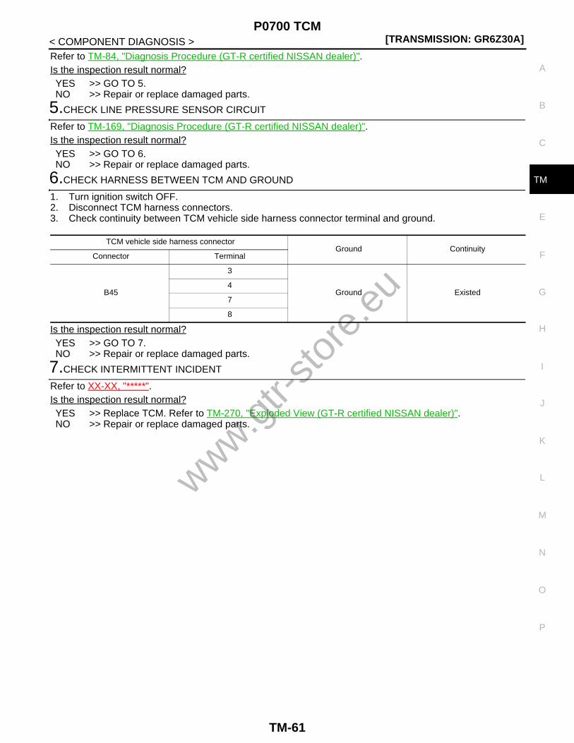
P0700 TCM[TRANSMISSION: GR6Z30A]
C
E
F
G
H
I
J
K
L
M
A
B
M
N
O
P
< COMPONENT DIAGNOSIS >
T
Refer to TM-84, "Diagnosis Procedure (GT-R certified NISSAN dealer)".Is the inspection result normal?YES >> GO TO 5.NO >> Repair or replace damaged parts.
5.CHECK LINE PRESSURE SENSOR CIRCUIT
Refer to TM-169, "Diagnosis Procedure (GT-R certified NISSAN dealer)".Is the inspection result normal?YES >> GO TO 6.NO >> Repair or replace damaged parts.
6.CHECK HARNESS BETWEEN TCM AND GROUND
1. Turn ignition switch OFF.2. Disconnect TCM harness connectors.3. Check continuity between TCM vehicle side harness connector terminal and ground.
Is the inspection result normal?YES >> GO TO 7.NO >> Repair or replace damaged parts.
7.CHECK INTERMITTENT INCIDENT
Refer to XX-XX, "*****".Is the inspection result normal?YES >> Replace TCM. Refer to TM-270, "Exploded View (GT-R certified NISSAN dealer)".NO >> Repair or replace damaged parts.
TCM vehicle side harness connectorGround Continuity
Connector Terminal
B45
3
Ground Existed4
7
8
www.gtr-
store
.eu
TM-61

[TRANSMISSION: GR6Z30A]P0705 RANGE SENSOR POWER SUPPLY
< COMPONENT DIAGNOSIS >
P0705 RANGE SENSOR POWER SUPPLY
Description (GT-R certified NISSAN dealer) INFOID:0000000004019839
• There are 2 different power supply systems for the range sensors; the range sensor power supply 1 systemdistributes power supply to 4 range sensors (No. 0, No. 1, No. 3, and No. 5) used for the range position rec-ognition, and the auto/manual range change switch changing between M range and A range. The rangesensor power supply 2 system distributes power supply to 2 range sensors (No. 2 and No. 4) used for therange position recognition.
• TCM recognizes the shift lever position by combining signals from 6 range sensors used for the range posi-tion recognition and park position switch.
DTC Logic (GT-R certified NISSAN dealer) INFOID:0000000004019840
DTC DETECTION LOGIC
DTC CONFIRMATION PROCEDURE
1.PREPARATION BEFORE OPERATION
If another “DTC CONFIRMATION PROCEDURE” is performed just before the next test, turn the ignitionswitch OFF and wait for 10 seconds or more, then perform the next test.
>> GO TO 2.
2.PERFORM DTC CONFIRMATION PROCEDURE
With CONSULT-III1. Start the engine.2. Shift the shift lever as per the following: P→R→N→A positions (Keep the shift lever for 5 seconds or more
at each position).
TCM recognized position Shift lever positionPark posi-tion switch
Range sensor
No. 0 No. 1 No. 2 No. 3 No. 4 No. 5
P P ON ON OFF OFF OFF OFF OFF
R R OFF OFF ON ON OFF OFF OFF
N N OFF OFF OFF ON ON ON OFF
A/M A/M OFF OFF OFF OFF OFF ON ON
DTC Self-diagnosis name DTC detection condition Possible cause
P0705
Range sensor power supply 1 system malfunction
A DTC is set if either of the following statuses is detected consecutively.1. Any of the range sensors No. 0, No. 1,
No. 3, or No. 5 is stuck to OFF.2. Any of the range sensors other than
those detected in 1 above is stuck to OFF.
• Range sensor• Harness or connector
(Open or shorted in the range sensor cir-cuit)
Range sensor power supply 2 system malfunction
A DTC is set if either of the following statuses is detected consecutively.1. Either of the range sensors No. 2 or No.
4 is stuck to OFF.2. Any of the range sensors other than
those detected in 1 above is/are stuck to OFF.
Control device malfunction
A DTC is set if 2 or more of the following sen-sors and switch are stuck to ON or OFF con-secutively: Range sensors No. 0, No. 1, No. 2, No. 3, No. 4 or No. 5, and park position switch.
• Range sensor• Park position switch• Harness or connector
(Open or shorted in the range sensor cir-cuit)(Open or shorted in the park position switch circuit)
www.gtr-
store
.eu
TM-62

P0705 RANGE SENSOR POWER SUPPLY[TRANSMISSION: GR6Z30A]
C
E
F
G
H
I
J
K
L
M
A
B
M
N
O
P
< COMPONENT DIAGNOSIS >
T
3. Shift the shift lever as per the following: A→N→R→P positions (Keep the shift lever for 5 seconds or moreat each position).
4. Repeat the procedure shown in 2 and 3 above 2 times.5. Check “Self Diagnostic Result” of “TRANSMISSION”.
Without CONSULT-III1. Start the engine.2. Shift the shift lever as per the following: P→R→N→A positions (Keep the shift lever for 5 seconds or more
at each position).3. Shift the shift lever as per the following: A→N→R→P positions (Keep the shift lever for 5 seconds or more
at each position).4. Repeat the procedure shown in 2 and 3 above 2 times.5. Check self-diagnosis.Is DTC P0705 detected?YES >> Go to TM-63, "Diagnosis Procedure (GT-R certified NISSAN dealer)".NO >> INSPECTION END
Diagnosis Procedure (GT-R certified NISSAN dealer) INFOID:0000000004019841
1.CHECK GROUND CONNECTION
1. Turn ignition switch OFF.2. Check ground connections B14 and B31 and ground cable connections. Refer to “Ground Inspection” in
XX-XX, "*****".Is the inspection result normal?YES >> GO TO 2.NO >> Repair or replace damaged parts.
2.CHECK TCM OUTPUT SIGNAL CIRCUIT (PART 1)
Check voltage between TCM vehicle side harness connector terminals.
Is the inspection result normal?YES >> GO TO 3.NO >> Go to TM-194, "Diagnosis Procedure (GT-R certified NISSAN dealer)".
3.CHECK TCM INPUT SIGNAL CIRCUIT
1. Turn ignition switch ON.2. Check voltage between TCM vehicle side harness connector terminals.
TCM vehicle side harness connectorCondition Voltage (Approx.)
Connector Terminal
B45
25
4
Ignition switch ON 5 V
Ignition switch OFF 0 V
26Ignition switch ON 5 V
Ignition switch OFF 0 V
www.gtr-
store
.eu
TM-63

[TRANSMISSION: GR6Z30A]P0705 RANGE SENSOR POWER SUPPLY
< COMPONENT DIAGNOSIS >
Is the inspection result normal?YES >> GO TO 4.NO >> GO TO 5.
4.CHECK INTERMITTENT INCIDENT
Refer to XX-XX, "*****".Is the inspection result normal?YES >> GO TO 9.NO >> Repair or replace damaged parts.
5.CHECK HARNESS BETWEEN TCM AND CONTROL DEVICE (RANGE SENSOR) (PART 1)
1. Turn ignition switch OFF.2. Disconnect TCM harness connectors and control device harness connector.3. Check continuity between TCM vehicle side harness connector terminals and control device vehicle side
harness connector terminals.
Is the inspection result normal?YES >> GO TO 6.NO >> Repair or replace damaged parts.
6.CHECK HARNESS BETWEEN TCM AND CONTROL DEVICE (RANGE SENSOR) (PART 2)
Check continuity between TCM vehicle side harness connector terminals and ground.
TCM vehicle side harness connectorCondition Voltage (Approx.)
Connector Terminal
B45
27
4
Shift lever: P position 0 V
Other than the above 5 V
33Shift lever: R position 0 V
Other than the above 5 V
35Shift lever: N position 0 V
Other than the above 5 V
38Shift lever: R, N position 0 V
Other than the above 5 V
43Shift lever: N, A, M position 0 V
Other than the above 5 V
44Shift lever: A, M position 0 V
Other than the above 5 V
TCM vehicle side harness connector Control device vehicle side harness connectorContinuity
Connector Terminal Connector Terminal
B45
25
B20
16
Existed
26 15
27 5
33 8
35 10
38 23
43 21
44 12
www.gtr-
store
.eu
TM-64

P0705 RANGE SENSOR POWER SUPPLY[TRANSMISSION: GR6Z30A]
C
E
F
G
H
I
J
K
L
M
A
B
M
N
O
P
< COMPONENT DIAGNOSIS >
T
Is the inspection result normal?YES >> GO TO 7.NO >> Repair or replace damaged parts.
7.CHECK HARNESS BETWEEN CONTROL DEVICE (RANGE SENSOR) AND GROUND
Check continuity between control device vehicle side harness connector terminals and ground.
Is the inspection result normal?YES >> GO TO 8.NO >> Repair or replace damaged parts.
8.CHECK INTERMITTENT INCIDENT
Refer to XX-XX, "*****".Is the inspection result normal?YES >> Replace control device assembly. Refer to TM-272, "Exploded View".NO >> Repair or replace damaged parts.
9.CHECK TCM OUTPUT SIGNAL CIRCUIT (PART 2)
1. Connect TCM harness connectors.2. Check voltage between TCM vehicle side harness connector terminals.
Is the inspection result normal?YES >> GO TO 10.NO >> Go to TM-194, "Diagnosis Procedure (GT-R certified NISSAN dealer)".
10.CHECK PARK POSITION SWITCH CIRCUIT
1. Disconnect TCM harness connectors.2. Check continuity between TCM vehicle side harness connector terminal and ground.
TCM vehicle side harness connectorGround Continuity
Connector Terminal
B45
25
Ground Not existed
26
27
33
35
38
43
44
Control device vehicle side harness connectorGround Continuity
Connector Terminal
B203
Ground Existed6
TCM vehicle side harness connectorCondition
Voltage (Ap-prox.)Connector Terminal Connector Terminal
B46 89 B45 4Ignition switch ON
Shift lever: P position 0 V
Other than the above 5 V
www.gtr-
store
.eu
TM-65

[TRANSMISSION: GR6Z30A]P0705 RANGE SENSOR POWER SUPPLY
< COMPONENT DIAGNOSIS >
Is the inspection result normal?YES >> GO TO 16.NO >> GO TO 11.
11.CHECK PARK POSITION SWITCH
1. Disconnect park position switch harness connector.2. Check park position switch. Refer to TM-67, "Component Inspection (Park Position Switch) (GT-R certi-
fied NISSAN dealer)".Is the inspection result normal?YES >> GO TO 12.NO >> Repair or replace damaged parts.
12.CHECK HARNESS BETWEEN TCM AND PARK POSITION SWITCH (PART 1)
Check continuity between TCM vehicle side harness connector terminal and park position switch vehicle sideharness connector terminal.
Is the inspection result normal?YES >> GO TO 13.NO >> Repair or replace damaged parts.
13.CHECK HARNESS BETWEEN TCM AND PARK POSITION SWITCH (PART 2)
Check continuity between TCM vehicle side harness connector terminal and ground.
Is the inspection result normal?YES >> GO TO 14.NO >> Repair or replace damaged parts.
14.CHECK HARNESS BETWEEN PARK POSITION SWITCH AND GROUND
Check continuity between park position switch vehicle side harness connector terminal and ground.
Is the inspection result normal?YES >> GO TO 15.NO >> Repair or replace damaged parts.
15.CHECK SHIFT POSITION
Check shift position. Refer to “INSPECTION” in TM-268, "Inspection and Adjustment".Is the inspection result normal?YES >> GO TO 16.NO >> Adjust shift position. Refer to “ADJUSTMENT” in TM-268, "Inspection and Adjustment".
TCM vehicle side harness connectorGround Condition Continuity
Connector Terminal
B46 89 GroundShift lever: P position Existed
Other than the above Not existed
TCM vehicle side harness connector Park position switch vehicle side harness connectorContinuity
Connector Terminal Connector Terminal
B46 89 B122 1 Existed
TCM vehicle side harness connectorGround Continuity
Connector Terminal
B46 89 Ground Not existed
Park position switch vehicle side harness connectorGround Continuity
Connector Terminal
B122 2 Ground Existed
www.gtr-
store
.eu
TM-66
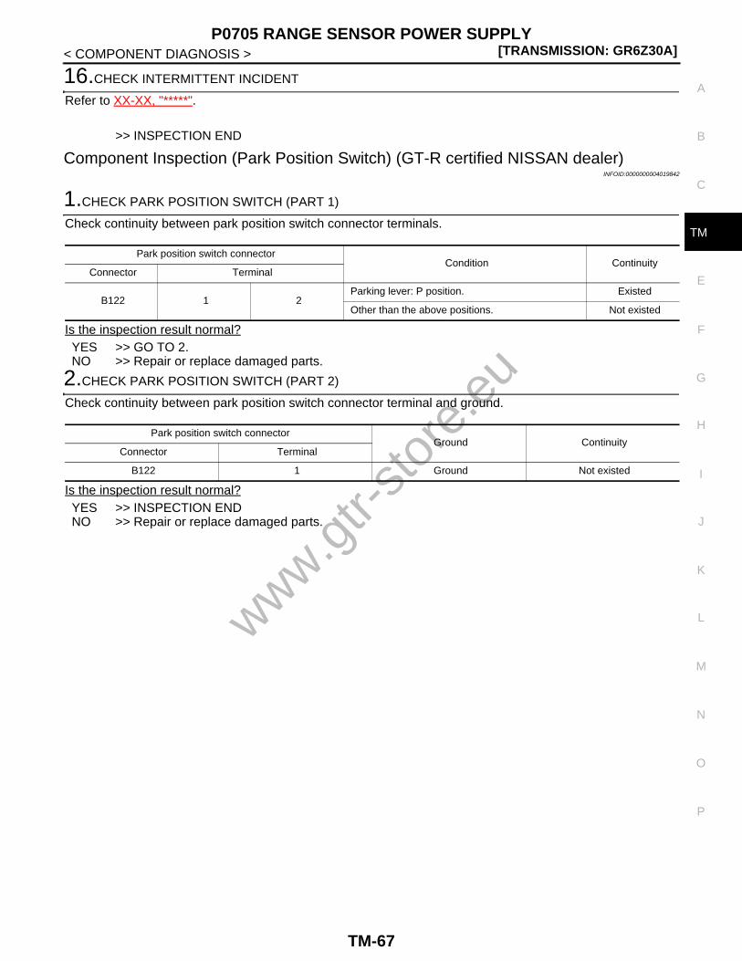
P0705 RANGE SENSOR POWER SUPPLY[TRANSMISSION: GR6Z30A]
C
E
F
G
H
I
J
K
L
M
A
B
M
N
O
P
< COMPONENT DIAGNOSIS >
T
16.CHECK INTERMITTENT INCIDENT
Refer to XX-XX, "*****".
>> INSPECTION END
Component Inspection (Park Position Switch) (GT-R certified NISSAN dealer)INFOID:0000000004019842
1.CHECK PARK POSITION SWITCH (PART 1)
Check continuity between park position switch connector terminals.
Is the inspection result normal?YES >> GO TO 2.NO >> Repair or replace damaged parts.
2.CHECK PARK POSITION SWITCH (PART 2)
Check continuity between park position switch connector terminal and ground.
Is the inspection result normal?YES >> INSPECTION ENDNO >> Repair or replace damaged parts.
Park position switch connectorCondition Continuity
Connector Terminal
B122 1 2Parking lever: P position. Existed
Other than the above positions. Not existed
Park position switch connectorGround Continuity
Connector Terminal
B122 1 Ground Not existed
www.gtr-
store
.eu
TM-67

[TRANSMISSION: GR6Z30A]P0706 RANGE SENSOR
< COMPONENT DIAGNOSIS >
P0706 RANGE SENSOR
Description (GT-R certified NISSAN dealer) INFOID:0000000004019843
• The range sensors are installed on the control device and the park position switch on the transmission,detecting the shift lever position.
• TCM recognizes the shift lever position by combining signals from 6 range sensors used for the range posi-tion recognition and park position switch.
DTC Logic (GT-R certified NISSAN dealer) INFOID:0000000004019844
DTC DETECTION LOGIC
DTC CONFIRMATION PROCEDURE
1.PREPARATION BEFORE OPERATION
If another “DTC CONFIRMATION PROCEDURE” is performed just before the next test, turn the ignitionswitch OFF and wait for 10 seconds or more, then perform the next test.
>> GO TO 2.
2.PERFORM DTC CONFIRMATION PROCEDURE
With CONSULT-III1. Start the engine.2. Shift the shift lever as per the following: P→R→N→A positions (Keep the shift lever for 5 seconds or more
at each position).3. Shift the shift lever as per the following: A→N→R→P positions (Keep the shift lever for 5 seconds or more
at each position).4. Repeat the procedure shown in 2 and 3 above 2 times.5. Check “Self Diagnostic Result” of “TRANSMISSION”.Is DTC P0706 detected?YES >> Go to TM-68, "Diagnosis Procedure (GT-R certified NISSAN dealer)".NO >> INSPECTION END
Diagnosis Procedure (GT-R certified NISSAN dealer) INFOID:0000000004019845
1.CHECK GROUND CONNECTION
1. Turn ignition switch OFF.2. Check ground connections B14 and B31 and ground cable connections. Refer to “Ground Inspection” in
XX-XX, "*****".Is the inspection result normal?
TCM recognized position Shift lever positionPark posi-tion switch
Range sensor
No. 0 No. 1 No. 2 No. 3 No. 4 No. 5
P P ON ON OFF OFF OFF OFF OFF
R R OFF OFF ON ON OFF OFF OFF
N N OFF OFF OFF ON ON ON OFF
A/M A/M OFF OFF OFF OFF OFF ON ON
DTC Self-diagnosis name DTC detection condition Possible cause
P0706Range sensors / park posi-tion switch malfunction
A DTC is set if any of the following sensors and switch is/are stuck to ON or OFF consec-utively: Range sensors No. 0, No. 1, No. 2, No. 3, No. 4 or No. 5, and park position switch.
• Range sensor• Park position switch• Harness or connector
(Open or shorted in the range sensor cir-cuit)(Open or shorted in the park position switch circuit)
www.gtr-
store
.eu
TM-68

P0706 RANGE SENSOR[TRANSMISSION: GR6Z30A]
C
E
F
G
H
I
J
K
L
M
A
B
M
N
O
P
< COMPONENT DIAGNOSIS >
T
YES >> GO TO 2.NO >> Repair or replace damaged parts.
2.CHECK TCM OUTPUT SIGNAL CIRCUIT (PART 1)
Check voltage between TCM vehicle side harness connector terminals.
Is the inspection result normal?YES >> GO TO 3.NO >> Go to TM-194, "Diagnosis Procedure (GT-R certified NISSAN dealer)".
3.CHECK TCM INPUT SIGNAL CIRCUIT
1. Turn ignition switch ON.2. Check voltage between TCM vehicle side harness connector terminals.
Is the inspection result normal?YES >> GO TO 4.NO >> GO TO 5.
4.CHECK INTERMITTENT INCIDENT
Refer to XX-XX, "*****".Is the inspection result normal?YES >> GO TO 9.NO >> Repair or replace damaged parts.
5.CHECK HARNESS BETWEEN TCM AND CONTROL DEVICE (RANGE SENSOR) (PART 1)
1. Turn ignition switch OFF.2. Disconnect TCM harness connectors and control device harness connector.3. Check continuity between TCM vehicle side harness connector terminals and control device vehicle side
harness connector terminals.
TCM vehicle side harness connectorCondition Voltage (Approx.)
Connector Terminal
B45
25
4
Ignition switch ON 5 V
Ignition switch OFF 0 V
26Ignition switch ON 5 V
Ignition switch OFF 0 V
TCM vehicle side harness connectorCondition Voltage (Approx.)
Connector Terminal
B45
27
4
Shift lever: P position 0 V
Other than the above 5 V
33Shift lever: R position 0 V
Other than the above 5 V
35Shift lever: N position 0 V
Other than the above 5 V
38Shift lever: R, N position 0 V
Other than the above 5 V
43Shift lever: N, A, M position 0 V
Other than the above 5 V
44Shift lever: A, M position 0 V
Other than the above 5 Vwww.gtr-
store
.eu
TM-69

[TRANSMISSION: GR6Z30A]P0706 RANGE SENSOR
< COMPONENT DIAGNOSIS >
Is the inspection result normal?YES >> GO TO 6.NO >> Repair or replace damaged parts.
6.CHECK HARNESS BETWEEN TCM AND CONTROL DEVICE (RANGE SENSOR) (PART 2)
Check continuity between TCM vehicle side harness connector terminals and ground.
Is the inspection result normal?YES >> GO TO 7.NO >> Repair or replace damaged parts.
7.CHECK HARNESS BETWEEN CONTROL DEVICE (RANGE SENSOR) AND GROUND
Check continuity between control device vehicle side harness connector terminals and ground.
Is the inspection result normal?YES >> GO TO 8.NO >> Repair or replace damaged parts.
8.CHECK INTERMITTENT INCIDENT
Refer to XX-XX, "*****".Is the inspection result normal?YES >> Replace control device assembly. Refer to TM-272, "Exploded View".NO >> Repair or replace damaged parts.
9.CHECK TCM OUTPUT SIGNAL CIRCUIT (PART 2)
1. Connect TCM harness connectors.
TCM vehicle side harness connector Control device vehicle side harness connectorContinuity
Connector Terminal Connector Terminal
B45
25
B20
16
Existed
26 15
27 5
33 8
35 10
38 23
43 21
44 12
TCM vehicle side harness connectorGround Continuity
Connector Terminal
B45
25
Ground Not existed
26
27
33
35
38
43
44
Control device vehicle side harness connectorGround Continuity
Connector Terminal
B203
Ground Existed6
www.gtr-
store
.eu
TM-70
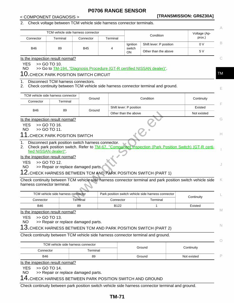
P0706 RANGE SENSOR[TRANSMISSION: GR6Z30A]
C
E
F
G
H
I
J
K
L
M
A
B
M
N
O
P
< COMPONENT DIAGNOSIS >
T
2. Check voltage between TCM vehicle side harness connector terminals.
Is the inspection result normal?YES >> GO TO 10.NO >> Go to TM-194, "Diagnosis Procedure (GT-R certified NISSAN dealer)".
10.CHECK PARK POSITION SWITCH CIRCUIT
1. Disconnect TCM harness connectors.2. Check continuity between TCM vehicle side harness connector terminal and ground.
Is the inspection result normal?YES >> GO TO 16.NO >> GO TO 11.
11.CHECK PARK POSITION SWITCH
1. Disconnect park position switch harness connector.2. Check park position switch. Refer to TM-67, "Component Inspection (Park Position Switch) (GT-R certi-
fied NISSAN dealer)".Is the inspection result normal?YES >> GO TO 12.NO >> Repair or replace damaged parts.
12.CHECK HARNESS BETWEEN TCM AND PARK POSITION SWITCH (PART 1)
Check continuity between TCM vehicle side harness connector terminal and park position switch vehicle sideharness connector terminal.
Is the inspection result normal?YES >> GO TO 13.NO >> Repair or replace damaged parts.
13.CHECK HARNESS BETWEEN TCM AND PARK POSITION SWITCH (PART 2)
Check continuity between TCM vehicle side harness connector terminal and ground.
Is the inspection result normal?YES >> GO TO 14.NO >> Repair or replace damaged parts.
14.CHECK HARNESS BETWEEN PARK POSITION SWITCH AND GROUND
Check continuity between park position switch vehicle side harness connector terminal and ground.
TCM vehicle side harness connectorCondition
Voltage (Ap-prox.)Connector Terminal Connector Terminal
B46 89 B45 4Ignition switch ON
Shift lever: P position 0 V
Other than the above 5 V
TCM vehicle side harness connectorGround Condition Continuity
Connector Terminal
B46 89 GroundShift lever: P position Existed
Other than the above Not existed
TCM vehicle side harness connector Park position switch vehicle side harness connectorContinuity
Connector Terminal Connector Terminal
B46 89 B122 1 Existed
TCM vehicle side harness connectorGround Continuity
Connector Terminal
B46 89 Ground Not existed
www.gtr-
store
.eu
TM-71

[TRANSMISSION: GR6Z30A]P0706 RANGE SENSOR
< COMPONENT DIAGNOSIS >
Is the inspection result normal?YES >> GO TO 15.NO >> Repair or replace damaged parts.
15.CHECK SHIFT POSITION
Check shift position. Refer to “INSPECTION” in TM-268, "Inspection and Adjustment".Is the inspection result normal?YES >> GO TO 16.NO >> Adjust shift position. Refer to “ADJUSTMENT” in TM-268, "Inspection and Adjustment".
16.CHECK INTERMITTENT INCIDENT
Refer to XX-XX, "*****".
>> INSPECTION END
Component Inspection (Park Position Switch) (GT-R certified NISSAN dealer)INFOID:0000000004019846
1.CHECK PARK POSITION SWITCH (PART 1)
Check continuity between park position switch connector terminals.
Is the inspection result normal?YES >> GO TO 2.NO >> Repair or replace damaged parts.
2.CHECK PARK POSITION SWITCH (PART 2)
Check continuity between park position switch connector terminal and ground.
Is the inspection result normal?YES >> INSPECTION ENDNO >> Repair or replace damaged parts.
Park position switch vehicle side harness connectorGround Continuity
Connector Terminal
B122 2 Ground Existed
Park position switch connectorCondition Continuity
Connector Terminal
B122 1 2Parking lever: P position. Existed
Other than the above positions. Not existed
Park position switch connectorGround Continuity
Connector Terminal
B122 1 Ground Not existed
www.gtr-
store
.eu
TM-72

P0710 FLUID TEMPERATURE SENSOR[TRANSMISSION: GR6Z30A]
C
E
F
G
H
I
J
K
L
M
A
B
M
N
O
P
< COMPONENT DIAGNOSIS >
T
P0710 FLUID TEMPERATURE SENSOR
Description (GT-R certified NISSAN dealer) INFOID:0000000004019847
• The fluid temperature sensor detects the transmission oil temperature in the oil pan.• The fluid temperature sensor converts the transmission oil temperature into output voltage and transmits the
signal to TCM.• The fluid temperature sensor uses a thermistor and its electrical resistance varies as the temperature varies.
The electrical resistance decreases as the temperature increases.
DTC Logic (GT-R certified NISSAN dealer) INFOID:0000000004019848
DTC DETECTION LOGICNOTE:If DTC P0700 is detected, first diagnose the DTC P0700. Refer to TM-58, "DTC Logic (GT-R certified NISSANdealer)".
DTC CONFIRMATION PROCEDURE
1.PREPARATION BEFORE OPERATION
If another “DTC CONFIRMATION PROCEDURE” is performed just before the next test, turn the ignitionswitch OFF and wait for 10 seconds or more, then perform the next test.
>> GO TO 2.
2.PERFORM DTC CONFIRMATION PROCEDURE
With CONSULT-III1. Start the engine and run at idle for 5 seconds or more.2. Check “Self Diagnostic Result” of “TRANSMISSION”.
Without CONSULT-III1. Start the engine and run at idle for 5 seconds or more.2. Check self-diagnosis.Is DTC P0710 detected?YES >> Go to TM-73, "Diagnosis Procedure (GT-R certified NISSAN dealer)".NO >> INSPECTION END
Diagnosis Procedure (GT-R certified NISSAN dealer) INFOID:0000000004019849
1.CHECK GROUND CONNECTION
1. Turn ignition switch OFF.2. Check ground connections B31 and ground cable connections. Refer to “Ground Inspection” in XX-XX,
"*****".Is the inspection result normal?YES >> GO TO 2.NO >> Repair or replace damaged parts.
2.CHECK FLUID TEMPERATURE SENSOR CIRCUIT (PART 1)
1. Disconnect TCM harness connectors.2. Check resistance between TCM vehicle side harness connector terminals.
DTC Self-diagnosis name DTC detection condition Possible cause
P0710Fluid temperature sensor system voltage
• A DTC is set if the fluid temperature sensor voltage value received by TCM is more than 2,654 mV.
• A DTC is set if the fluid temperature sensor voltage value received by TCM is less than 39 mV.
• Fluid temperature sensor• Harness or connector
(Open or shorted in the fluid temperature sensor circuit)
www.gtr-
store
.eu
TM-73

[TRANSMISSION: GR6Z30A]P0710 FLUID TEMPERATURE SENSOR
< COMPONENT DIAGNOSIS >
Is the inspection result normal?YES >> GO TO 3.NO >> GO TO 4.
3.CHECK FLUID TEMPERATURE SENSOR CIRCUIT (PART 2)
Check continuity between TCM vehicle side harness connector terminals and ground.
Is the inspection result normal?YES >> GO TO 7.NO >> GO TO 4.
4.CHECK FLUID TEMPERATURE SENSOR
1. Disconnect transmission unit harness connectors.2. Check fluid temperature sensor. Refer to TM-75, "Component Inspection (Fluid Temperature Sensor)
(GT-R certified NISSAN dealer)".Is the inspection result normal?YES >> GO TO 5.NO >> Repair or replace damaged parts.
5.CHECK HARNESS BETWEEN TCM AND TRANSMISSION (FLUID TEMPERATURE SENSOR) (PART 1)
Check continuity between TCM vehicle side harness connector terminals and transmission unit vehicle sideharness connector terminals.
Is the inspection result normal?YES >> GO TO 6.NO >> Repair or replace damaged parts.
6.CHECK HARNESS BETWEEN TCM AND TRANSMISSION (FLUID TEMPERATURE SENSOR) (PART 2)
Check continuity between TCM vehicle side harness connector terminals and ground.
Is the inspection result normal?YES >> GO TO 7.NO >> Repair or replace damaged parts.
7.CHECK INTERMITTENT INCIDENT
TCM vehicle side harness connectorCondition
Resistance (Ap-prox.)Connector Terminal
B46 87 91
Transmission oil temperature: 20°C (68°F) 6.36 – 6.68 kΩ
Transmission oil temperature: 50°C (122°F) 2.17 – 2.23 kΩ
Transmission oil temperature: 80°C (176°F) 0.86 – 0.89 kΩ
TCM vehicle side harness connectorGround Continuity
Connector Terminal
B4687
Ground Not existed91
TCM vehicle side harness connector Transmission unit vehicle side harness connectorContinuity
Connector Terminal Connector Terminal
B4687
B5045
Existed91 46
TCM vehicle side harness connectorGround Continuity
Connector Terminal
B4687
Ground Not existed91
www.gtr-
store
.eu
TM-74

P0710 FLUID TEMPERATURE SENSOR[TRANSMISSION: GR6Z30A]
C
E
F
G
H
I
J
K
L
M
A
B
M
N
O
P
< COMPONENT DIAGNOSIS >
T
Refer to XX-XX, "*****".
>> INSPECTION END
Component Inspection (Fluid Temperature Sensor) (GT-R certified NISSAN dealer)INFOID:0000000004019850
1.CHECK FLUID TEMPERATURE SENSOR (PART 1)
Check resistance between transmission unit harness connector terminals.
Is the inspection result normal?YES >> GO TO 2.NO >> Repair or replace damaged parts.
2.CHECK FLUID TEMPERATURE SENSOR (PART 2)
Check continuity between transmission unit harness connector terminal and ground.
Is the inspection result normal?YES >> INSPECTION ENDNO >> Repair or replace damaged parts.
Transmission unit harness connectorCondition
Resistance (Ap-prox.)Connector Terminal
B50 45 46
Transmission oil temperature: 20°C (68°F) 6.36 – 6.68 kΩ
Transmission oil temperature: 50°C (122°F) 2.17 – 2.23 kΩ
Transmission oil temperature: 80°C (176°F) 0.86 – 0.89 kΩ
Transmission unit harness connectorGround Continuity
Connector Terminal
B50 45 Ground Not existed
www.gtr-
store
.eu
TM-75

[TRANSMISSION: GR6Z30A]P0711 FLUID TEMPERATURE SENSOR FUNCTION
< COMPONENT DIAGNOSIS >
P0711 FLUID TEMPERATURE SENSOR FUNCTION
Description (GT-R certified NISSAN dealer) INFOID:0000000004019851
• The fluid temperature sensor detects the transmission oil temperature in the oil pan.• The fluid temperature sensor converts the transmission oil temperature into output voltage and transmits the
signal to TCM. • The fluid temperature sensor uses a thermistor and its electrical resistance varies as the temperature varies.
The electrical resistance decreases as the temperature increases.
DTC Logic (GT-R certified NISSAN dealer) INFOID:0000000004019852
DTC DETECTION LOGICNOTE:If DTC P0710 is detected, first diagnose the DTC P0710. Refer to TM-73, "DTC Logic (GT-R certified NISSANdealer)".
DTC CONFIRMATION PROCEDURE
1.PREPARATION BEFORE OPERATION
If another “DTC CONFIRMATION PROCEDURE” is performed just before the next test, turn the ignitionswitch OFF and wait for 10 seconds or more, then perform the next test.
>> GO TO 2.
2.PERFORM DTC CONFIRMATION PROCEDURE
With CONSULT-III1. Start the engine and run at idle for 8 minutes or more.2. Check “Self Diagnostic Result” of “TRANSMISSION”.
Without CONSULT-III1. Start the engine and run at idle for 8 minutes or more.2. Check self-diagnosis.Is DTC P0711 detected?YES >> Go to TM-76, "Diagnosis Procedure (GT-R certified NISSAN dealer)".NO >> INSPECTION END
Diagnosis Procedure (GT-R certified NISSAN dealer) INFOID:0000000004019853
1.CHECK GROUND CONNECTION
1. Turn ignition switch OFF.2. Check ground connections B31 and ground cable connections. Refer to “Ground Inspection” in XX-XX,
"*****".Is the inspection result normal?YES >> GO TO 2.
DTC Self-diagnosis name DTC detection condition Possible cause
P0711Fluid temperature sensor malfunction judgment
• A DTC is set if TCM detects the fluid tem-perature sensor value of 160°C (320°F) or more for a certain period of time.
• A DTC is set if TCM detects the fluid tem-perature sensor value of 0°C (32°F) or more and less than 20°C (68°F) for a cer-tain period of time.
• A DTC is set if TCM detects the fluid tem-perature sensor value of −20°C (−4°F) or more, or less than 0°C (32°F) for a certain period of time.
• A DTC is set if TCM detects the fluid tem-perature sensor value of less than −20°C (−4°F) for a certain period of time.
• Fluid temperature sensor• Harness or connector
(Open or shorted in the fluid temperature sensor circuit)
www.gtr-
store
.eu
TM-76

P0711 FLUID TEMPERATURE SENSOR FUNCTION[TRANSMISSION: GR6Z30A]
C
E
F
G
H
I
J
K
L
M
A
B
M
N
O
P
< COMPONENT DIAGNOSIS >
T
NO >> Repair or replace damaged parts.
2.CHECK FLUID TEMPERATURE SENSOR CIRCUIT (PART 1)
1. Disconnect TCM harness connectors.2. Check resistance between TCM vehicle side harness connector terminals.
Is the inspection result normal?YES >> GO TO 3.NO >> GO TO 4.
3.CHECK FLUID TEMPERATURE SENSOR CIRCUIT (PART 2)
Check continuity between TCM vehicle side harness connector terminals and ground.
Is the inspection result normal?YES >> GO TO 7.NO >> GO TO 4.
4.CHECK FLUID TEMPERATURE SENSOR
1. Disconnect transmission unit harness connectors.2. Check fluid temperature sensor. Refer to TM-78, "Component Inspection (Fluid Temperature Sensor)
(GT-R certified NISSAN dealer)".Is the inspection result normal?YES >> GO TO 5.NO >> Repair or replace damaged parts.
5.CHECK HARNESS BETWEEN TCM AND TRANSMISSION (FLUID TEMPERATURE SENSOR) (PART 1)
Check continuity between TCM vehicle side harness connector terminals and transmission unit vehicle sideharness connector terminals.
Is the inspection result normal?YES >> GO TO 6.NO >> Repair or replace damaged parts.
6.CHECK HARNESS BETWEEN TCM AND TRANSMISSION (FLUID TEMPERATURE SENSOR) (PART 2)
Check continuity between TCM vehicle side harness connector terminals and ground.
TCM vehicle side harness connectorCondition
Resistance (Ap-prox.)Connector Terminal
B46 87 91
Transmission oil temperature: 20°C (68°F) 6.36 – 6.68 kΩ
Transmission oil temperature: 50°C (122°F) 2.17 – 2.23 kΩ
Transmission oil temperature: 80°C (176°F) 0.86 – 0.89 kΩ
TCM vehicle side harness connectorGround Continuity
Connector Terminal
B4687
Ground Not existed91
TCM vehicle side harness connector Transmission unit vehicle side harness connectorContinuity
Connector Terminal Connector Terminal
B4687
B5045
Existed91 46
TCM vehicle side harness connectorGround Continuity
Connector Terminal
B4687
Ground Not existed91
www.gtr-
store
.eu
TM-77

[TRANSMISSION: GR6Z30A]P0711 FLUID TEMPERATURE SENSOR FUNCTION
< COMPONENT DIAGNOSIS >Is the inspection result normal?YES >> GO TO 7.NO >> Repair or replace damaged parts.
7.CHECK INTERMITTENT INCIDENT
Refer to XX-XX, "*****".Is the inspection result normal?YES >> Replace transmission assembly. Refer to TM-291, "Exploded View (GT-R certified NISSAN
dealer)".NO >> Repair or replace damaged parts.
Component Inspection (Fluid Temperature Sensor) (GT-R certified NISSAN dealer)INFOID:0000000004019854
1.CHECK FLUID TEMPERATURE SENSOR (PART 1)
Check resistance between transmission unit harness connector terminals.
Is the inspection result normal?YES >> GO TO 2.NO >> Repair or replace damaged parts.
2.CHECK FLUID TEMPERATURE SENSOR (PART 2)
Check continuity between transmission unit harness connector terminal and ground.
Is the inspection result normal?YES >> INSPECTION ENDNO >> Repair or replace damaged parts.
Transmission unit harness connectorCondition
Resistance (Ap-prox.)Connector Terminal
B50 45 46
Transmission oil temperature: 20°C (68°F) 6.36 – 6.68 kΩ
Transmission oil temperature: 50°C (122°F) 2.17 – 2.23 kΩ
Transmission oil temperature: 80°C (176°F) 0.86 – 0.89 kΩ
Transmission unit harness connectorGround Continuity
Connector Terminal
B50 45 Ground Not existed
www.gtr-
store
.eu
TM-78

P0715 CLUTCH A SPEED SENSOR[TRANSMISSION: GR6Z30A]
C
E
F
G
H
I
J
K
L
M
A
B
M
N
O
P
< COMPONENT DIAGNOSIS >
T
P0715 CLUTCH A SPEED SENSOR
Description (GT-R certified NISSAN dealer) INFOID:0000000004019855
• The clutch A speed sensor detects the 2nd counter gear speed. The clutch A speed sensor converts the 2ndcounter gear speed into pulse signal and transmits the signal to TCM.
• TCM calculates the revolution speed or the clutch A (even gear) based on the signal from the clutch A speedsensor.
DTC Logic (GT-R certified NISSAN dealer) INFOID:0000000004019856
DTC DETECTION LOGIC
DTC CONFIRMATION PROCEDURECAUTION:Be careful of the driving speed.
1.PREPARATION BEFORE OPERATION
If another “DTC CONFIRMATION PROCEDURE” is performed just before the next test, turn the ignitionswitch OFF and wait for 10 seconds or more, then perform the next test.
>> GO TO 2.
2.PERFORM DTC CONFIRMATION PROCEDURE
With CONSULT-III1. Start the engine.2. Select “RANGE”, “GEAR” and “ENGINE SPEED” in “Data Monitor”.3. Run the vehicle and maintain the following conditions for 5 seconds or more.
4. Check “Self Diagnostic Result” of “TRANSMISSION”.Without CONSULT-III
1. Start the engine.2. Run the vehicle and maintain the following conditions for 5 seconds or more.
3. Check self-diagnosis.Is DTC P0715 detected?YES >> Go to TM-80, "Diagnosis Procedure (GT-R certified NISSAN dealer)".NO >> INSPECTION END
DTC Self-diagnosis name DTC detection condition Possible cause
P0715Clutch A speed pulse signal compatibility
A DTC is set if the status 1 or 2 below is de-tected with sleeve A1 or A2 engaged in an even gear.1. The difference between the actual out-
put shaft speed and the output shaft speed converted from the clutch A speed is 1,000 rpm or more.
2. The difference between the vehicle speed signal (meter) (CAN signal) and the output shaft speed converted from the clutch A speed is 1,000 rpm or more.
• Clutch A speed sensor• Harness or connector
(Open or short in the clutch A speed sen-sor circuit)
RANGE : M
GEAR : 4
ENGINE SPEED : 1,500 rpm or more
Shift lever : M range
Gear : 4
Engine speed : 1,500 rpm or more
www.gtr-
store
.eu
TM-79

[TRANSMISSION: GR6Z30A]P0715 CLUTCH A SPEED SENSOR
< COMPONENT DIAGNOSIS >
Diagnosis Procedure (GT-R certified NISSAN dealer) INFOID:0000000004019857
1.CHECK GROUND CONNECTION
1. Turn ignition switch OFF.2. Check ground connections B31 and ground cable connections. Refer to “Ground Inspection” in XX-XX,
"*****".Is the inspection result normal?YES >> GO TO 2.NO >> Repair or replace damaged parts.
2.CHECK TCM OUTPUT SIGNAL CIRCUIT
Check voltage between TCM vehicle side harness connector terminals.
Is the inspection result normal?YES >> GO TO 3.NO >> Go to TM-194, "Diagnosis Procedure (GT-R certified NISSAN dealer)".
3.CHECK TCM INPUT SIGNAL CIRCUIT
1. Start engine.2. Check voltage between TCM vehicle side harness connector terminals.
Is the inspection result normal?YES >> GO TO 4.NO >> GO TO 5.
4.CHECK INTERMITTENT INCIDENT
Refer to XX-XX, "*****".
>> INSPECTION END
5.CHECK HARNESS BETWEEN TCM AND TRANSMISSION (CLUTCH A SPEED SENSOR) (PART 1)
Check continuity between TCM vehicle side harness connector terminals and transmission unit vehicle sideharness connector terminals.
Is the inspection result normal?
TCM vehicle side harness connectorCondition Voltage (Approx.)
Connector Terminal
B46 76 4Ignition switch ON 5 V
Ignition switch OFF 0 V
TCM vehicle side harness connectorCondition Voltage (Approx.)
Connector Terminal
B46 72 4• M range, 2nd gear• Engine speed: 2,000 rpm
NNDIA0061ZZ
TCM vehicle side harness connector Transmission unit vehicle side harness connectorContinuity
Connector Terminal Connector Terminal
B46
68
B49
29
Existed72 34
76 28
www.gtr-
store
.eu
TM-80

P0715 CLUTCH A SPEED SENSOR[TRANSMISSION: GR6Z30A]
C
E
F
G
H
I
J
K
L
M
A
B
M
N
O
P
< COMPONENT DIAGNOSIS >
T
YES >> GO TO 6.NO >> Repair or replace damaged parts.
6.CHECK HARNESS BETWEEN TCM AND TRANSMISSION (CLUTCH A SPEED SENSOR) (PART 2)
Check continuity between TCM vehicle side harness connector terminals and ground.
Is the inspection result normal?YES >> GO TO 7.NO >> Repair or replace damaged parts.
7.CHECK INTERMITTENT INCIDENT
Refer to XX-XX, "*****".Is the inspection result normal?YES >> Replace transmission assembly. Refer to TM-291, "Exploded View (GT-R certified NISSAN
dealer)".NO >> Repair or replace damaged parts.
TCM vehicle side harness connectorGround Continuity
Connector Terminal
B46
68
Ground Not existed72
76
www.gtr-
store
.eu
TM-81

[TRANSMISSION: GR6Z30A]P0720 OUTPUT SHAFT SPEED SENSOR
< COMPONENT DIAGNOSIS >
P0720 OUTPUT SHAFT SPEED SENSOR
Description (GT-R certified NISSAN dealer) INFOID:0000000004019858
• The output shaft speed sensor detects the front reduction gear speed. The output shaft speed sensor con-verts the front reduction gear speed into pulse signal and transmits the signal to TCM.
• The vehicle speed signal (meter) is transmitted via the CAN communication from the ABS actuator and elec-tric unit (control unit) through the combination meter to TCM. TCM calculates the output shaft speed basedon the vehicle speed signal (meter) and uses it for the diagnosis of each speed sensor and as a backup sig-nal.
DTC Logic (GT-R certified NISSAN dealer) INFOID:0000000004019859
DTC DETECTION LOGICNOTE:If DTC U1000 is detected, first diagnose the DTC U1000. Refer to TM-57, "DTC Logic (GT-R certified NISSANdealer)".
www.gtr-
store
.eu
TM-82

P0720 OUTPUT SHAFT SPEED SENSOR[TRANSMISSION: GR6Z30A]
C
E
F
G
H
I
J
K
L
M
A
B
M
N
O
P
< COMPONENT DIAGNOSIS >
T
• *1: A DTC is displayed when A or B in the DTC detection conditions is detected.
• *2: A DTC is displayed when C or D in the DTC detection conditions is detected.
DTC CONFIRMATION PROCEDURECAUTION:Be careful of the driving speed.
1.PREPARATION BEFORE OPERATION
If another “DTC CONFIRMATION PROCEDURE” is performed just before the next test, turn the ignitionswitch OFF and wait for 10 seconds or more, then perform the next test.
DTC Self-diagnosis name DTC detection condition Possible cause
P0720
Output shaft speed CAN sig-
nal compatibility *1
A
A DTC is set if the status 1 or 2 below is detected with an even gear engaged.1. The difference between the output
shaft speed sensor value and the output shaft speed converted from the vehicle speed signal (meter) (CAN signal) is 1,000 rpm or more.
2. The difference between the output shaft speed converted from the vehicle speed signal (meter) (CAN signal) and the output shaft speed converted from the clutch A speed is 1,000 rpm or more.
• Combination meter• ABS actuator and electric unit (control
unit)• Wheel sensor• Harness or connector
(CAN communication line is open or short-ed)(Open or short in the wheel speed sensor circuit)
B
A DTC is set if the status 1 or 2 below is detected with an odd gear engaged.1. The difference between the output
shaft speed sensor value and the output shaft speed converted from the vehicle speed signal (meter) (CAN signal) is 1,000 rpm or more.
2. The difference between the output shaft speed converted from the vehicle speed signal (meter) (CAN signal) and the output shaft speed converted from the clutch B speed is 1,000 rpm or more.
Output shaft speed pulse
signal compatibility *2
C
A DTC is set if the status 1 or 2 below is detected with an even gear engaged.1. The difference between the output
shaft speed sensor value and the output shaft speed converted from the vehicle speed signal (meter) (CAN signal) is 1,000 rpm or more.
2. The difference between the output shaft speed sensor value and the output shaft speed converted from the clutch A speed is 1,000 rpm or more.
• Output shaft speed sensor• Harness or connector
(Open or shorted in the output shaft speed sensor circuit)
D
A DTC is set if the status 1 or 2 below is detected with an odd gear engaged.1. The difference between the output
shaft speed sensor value and the output shaft speed converted from the vehicle speed signal (meter) (CAN signal) is 1,000 rpm or more.
2. The difference between the output shaft speed sensor value and the output shaft speed converted from the clutch B speed is 1,000 rpm or more.
www.gtr-
store
.eu
TM-83
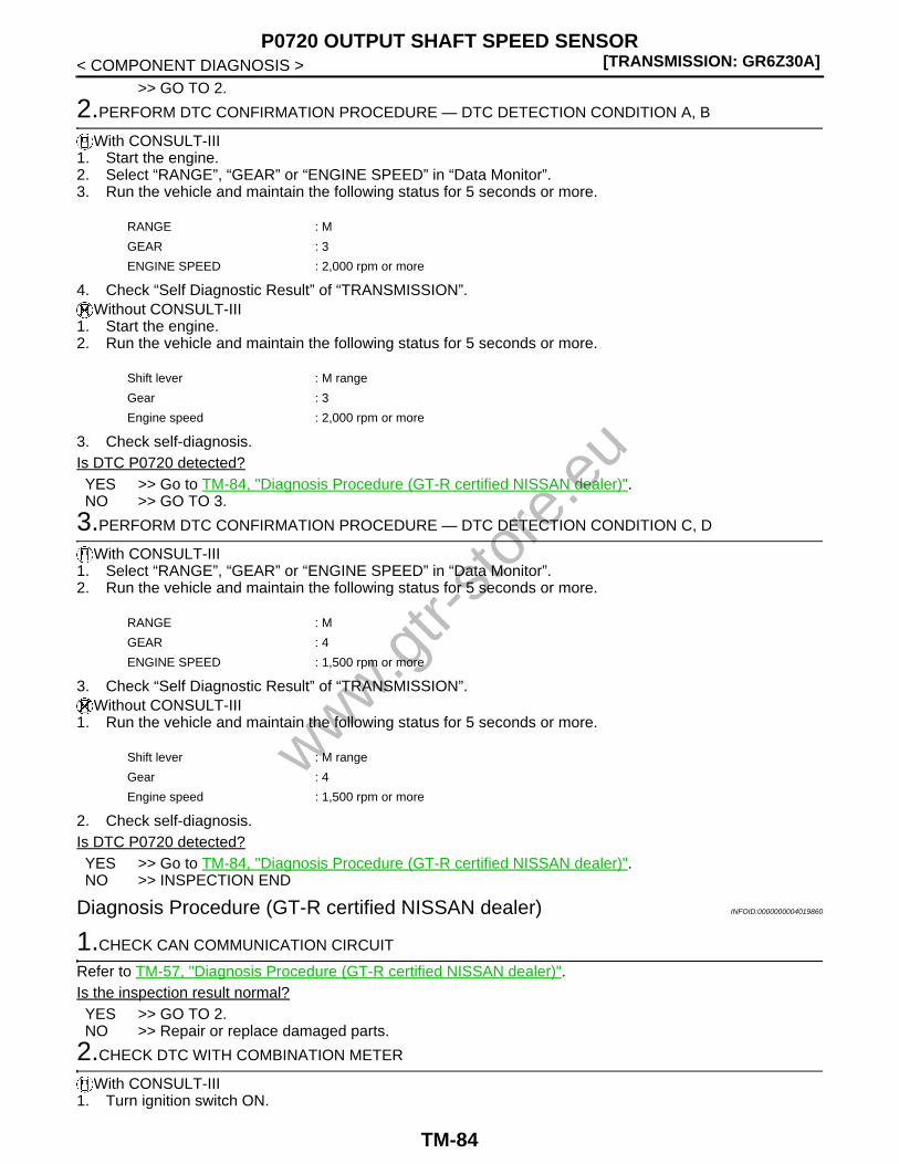
[TRANSMISSION: GR6Z30A]P0720 OUTPUT SHAFT SPEED SENSOR
< COMPONENT DIAGNOSIS >>> GO TO 2.
2.PERFORM DTC CONFIRMATION PROCEDURE — DTC DETECTION CONDITION A, B
With CONSULT-III1. Start the engine.2. Select “RANGE”, “GEAR” or “ENGINE SPEED” in “Data Monitor”.3. Run the vehicle and maintain the following status for 5 seconds or more.
4. Check “Self Diagnostic Result” of “TRANSMISSION”.Without CONSULT-III
1. Start the engine.2. Run the vehicle and maintain the following status for 5 seconds or more.
3. Check self-diagnosis.Is DTC P0720 detected?YES >> Go to TM-84, "Diagnosis Procedure (GT-R certified NISSAN dealer)".NO >> GO TO 3.
3.PERFORM DTC CONFIRMATION PROCEDURE — DTC DETECTION CONDITION C, D
With CONSULT-III1. Select “RANGE”, “GEAR” or “ENGINE SPEED” in “Data Monitor”.2. Run the vehicle and maintain the following status for 5 seconds or more.
3. Check “Self Diagnostic Result” of “TRANSMISSION”. Without CONSULT-III
1. Run the vehicle and maintain the following status for 5 seconds or more.
2. Check self-diagnosis.Is DTC P0720 detected?YES >> Go to TM-84, "Diagnosis Procedure (GT-R certified NISSAN dealer)".NO >> INSPECTION END
Diagnosis Procedure (GT-R certified NISSAN dealer) INFOID:0000000004019860
1.CHECK CAN COMMUNICATION CIRCUIT
Refer to TM-57, "Diagnosis Procedure (GT-R certified NISSAN dealer)".Is the inspection result normal?YES >> GO TO 2.NO >> Repair or replace damaged parts.
2.CHECK DTC WITH COMBINATION METER
With CONSULT-III1. Turn ignition switch ON.
RANGE : M
GEAR : 3
ENGINE SPEED : 2,000 rpm or more
Shift lever : M range
Gear : 3
Engine speed : 2,000 rpm or more
RANGE : M
GEAR : 4
ENGINE SPEED : 1,500 rpm or more
Shift lever : M range
Gear : 4
Engine speed : 1,500 rpm or more
www.gtr-
store
.eu
TM-84
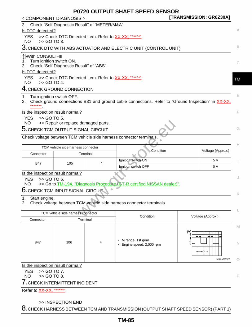
P0720 OUTPUT SHAFT SPEED SENSOR[TRANSMISSION: GR6Z30A]
C
E
F
G
H
I
J
K
L
M
A
B
M
N
O
P
< COMPONENT DIAGNOSIS >
T
2. Check “Self Diagnostic Result” of “METER/M&A”.Is DTC detected?YES >> Check DTC Detected Item. Refer to XX-XX, "*****".NO >> GO TO 3.
3.CHECK DTC WITH ABS ACTUATOR AND ELECTRIC UNIT (CONTROL UNIT)
With CONSULT-III1. Turn ignition switch ON.2. Check “Self Diagnostic Result” of “ABS”.Is DTC detected?YES >> Check DTC Detected Item. Refer to XX-XX, "*****".NO >> GO TO 4.
4.CHECK GROUND CONNECTION
1. Turn ignition switch OFF.2. Check ground connections B31 and ground cable connections. Refer to “Ground Inspection” in XX-XX,
"*****".Is the inspection result normal?YES >> GO TO 5.NO >> Repair or replace damaged parts.
5.CHECK TCM OUTPUT SIGNAL CIRCUIT
Check voltage between TCM vehicle side harness connector terminals.
Is the inspection result normal?YES >> GO TO 6.NO >> Go to TM-194, "Diagnosis Procedure (GT-R certified NISSAN dealer)".
6.CHECK TCM INPUT SIGNAL CIRCUIT
1. Start engine.2. Check voltage between TCM vehicle side harness connector terminals.
Is the inspection result normal?YES >> GO TO 7.NO >> GO TO 8.
7.CHECK INTERMITTENT INCIDENT
Refer to XX-XX, "*****".
>> INSPECTION END
8.CHECK HARNESS BETWEEN TCM AND TRANSMISSION (OUTPUT SHAFT SPEED SENSOR) (PART 1)
TCM vehicle side harness connectorCondition Voltage (Approx.)
Connector Terminal
B47 105 4Ignition switch ON 5 V
Ignition switch OFF 0 V
TCM vehicle side harness connectorCondition Voltage (Approx.)
Connector Terminal
B47 106 4• M range, 1st gear• Engine speed: 2,000 rpm
NNDIA0055ZZ
www.gtr-
store
.eu
TM-85

[TRANSMISSION: GR6Z30A]P0720 OUTPUT SHAFT SPEED SENSOR
< COMPONENT DIAGNOSIS >Check continuity between TCM vehicle side harness connector terminals and transmission unit vehicle sideharness connector terminals.
Is the inspection result normal?YES >> GO TO 9.NO >> Repair or replace damaged parts.
9.CHECK HARNESS BETWEEN TCM AND TRANSMISSION (OUTPUT SHAFT SPEED SENSOR) (PART 2)
Check continuity between TCM vehicle side harness connector terminals and ground.
Is the inspection result normal?YES >> GO TO 10.NO >> Repair or replace damaged parts.
10.CHECK INTERMITTENT INCIDENT
Refer to XX-XX, "*****".Is the inspection result normal?YES >> Replace transmission assembly. Refer to TM-291, "Exploded View (GT-R certified NISSAN
dealer)".NO >> Repair or replace damaged parts.
TCM vehicle side harness connector Transmission unit vehicle side harness connectorContinuity
Connector Terminal Connector Terminal
B47
105
B49
1
Existed106 2
107 8
TCM vehicle side harness connectorGround Continuity
Connector Terminal
B47
105
Ground Not existed106
107
www.gtr-
store
.eu
TM-86

P0725 ENGINE SPEED SIGNAL[TRANSMISSION: GR6Z30A]
C
E
F
G
H
I
J
K
L
M
A
B
M
N
O
P
< COMPONENT DIAGNOSIS >
T
P0725 ENGINE SPEED SIGNAL
Description (GT-R certified NISSAN dealer) INFOID:0000000004019861
• The engine speed signal (CAN signal) is transmitted from ECM to TCM via CAN communication.• The engine speed signal (pulse signal) is transmitted from ECM to TCM via the hard wire. TCM uses the
engine speed signal (pulse signal) for the diagnosis of each speed signal and as a backup signal.
DTC Logic (GT-R certified NISSAN dealer) INFOID:0000000004019862
DTC DETECTION LOGICNOTE:If DTC P0700 is detected, first diagnose the DTC P0700. Refer to TM-58, "DTC Logic (GT-R certified NISSANdealer)".
*: A DTC is displayed when A, B or C in the DTC detection conditions is detected.
DTC CONFIRMATION PROCEDURECAUTION:Be careful of the driving speed.
1.PREPARATION BEFORE OPERATION
If another “DTC CONFIRMATION PROCEDURE” is performed just before the next test, turn the ignitionswitch OFF and wait for 10 seconds or more, then perform the next test.
>> GO TO 2.
2.PERFORM DTC CONFIRMATION PROCEDURE — DTC DETECTION CONDITION A
With CONSULT-III1. Start the engine and run at idle for 5 seconds or more.2. Check “Self Diagnostic Result” of “TRANSMISSION”.Is DTC P0725 detected?YES >> Go to TM-88, "Diagnosis Procedure (GT-R certified NISSAN dealer)".NO >> GO TO 3.
3.PERFORM DTC CONFIRMATION PROCEDURE — DTC DETECTION CONDITION D
With CONSULT-III1. Select “RANGE” and “ENGINE SPEED” in “Data Monitor”.
DTC Self-diagnosis name DTC detection condition Possible cause
P0725
Engine speed CAN signal
compatibility*
A
A DTC is set if the engine speed (CAN signal) is less than 200 rpm when the engine speed (pulse signal) is 700 rpm or more.
Harness or connector(CAN communication line is open or short-ed)
B
A DTC is set if the difference between the engine speed (CAN signal) and clutch A speed sensor value is 1,000 rpm or more with clutch A engaged.
• Clutch A speed sensor• Harness or connector
(Open or short in the clutch A speed sen-sor circuit)(CAN communication line is open or short-ed)
C
A DTC is set if the difference between the engine speed (CAN signal) and clutch B speed sensor value is 1,000 rpm or more with clutch B engaged.
• Clutch B speed sensor• Harness or connector
(Open or short in the clutch B speed sen-sor circuit)(CAN communication line is open or short-ed)
Engine speed pulse signal compatibility
D
A DTC is set if the engine speed (pulse signal) is less than 500 rpm when the engine speed (CAN signal) is 1,000 rpm or more.
Harness or connector(Open or short in the circuit between ECM and TCM)
www.gtr-
store
.eu
TM-87

[TRANSMISSION: GR6Z30A]P0725 ENGINE SPEED SIGNAL
< COMPONENT DIAGNOSIS >2. Maintain the following conditions for 5 seconds or more.
3. Check “Self Diagnostic Result” of “TRANSMISSION”.Is DTC P0725 detected?YES >> Go to TM-88, "Diagnosis Procedure (GT-R certified NISSAN dealer)".NO >> GO TO 4.
4.PERFORM DTC CONFIRMATION PROCEDURE — DTC DETECTION CONDITION C
With CONSULT-III1. Select “RANGE”, “GEAR”, “ACCEL POSI SEN 1” and “VEHICLE SPEED” in “Data Monitor”.2. Run the vehicle and maintain the following conditions for 5 seconds or more.
3. Check “Self Diagnostic Result” of “TRANSMISSION”.Is DTC P0725 detected?YES >> Go to TM-88, "Diagnosis Procedure (GT-R certified NISSAN dealer)".NO >> GO TO 5.
5.DTC CONFIRMATION PROCEDURE — DTC DETECTION CONDITION B
With CONSULT-III1. Select “RANGE”, “GEAR”, “ACCEL POSI SEN 1” and “VEHICLE SPEED” in “Data Monitor”.2. Run the vehicle and maintain the following conditions for 5 seconds or more.
3. Check “Self Diagnostic Result” of “TRANSMISSION”.Is DTC P0725 detected?YES >> Go to TM-88, "Diagnosis Procedure (GT-R certified NISSAN dealer)".NO >> INSPECTION END
Diagnosis Procedure (GT-R certified NISSAN dealer) INFOID:0000000004019863
1.CHECK CAN COMMUNICATION CIRCUIT
Refer to TM-57, "Diagnosis Procedure (GT-R certified NISSAN dealer)".Is the inspection result normal?YES >> GO TO 2.NO >> Repair or replace damaged parts.
2.CHECK CLUTCH A SPEED SENSOR CIRCUIT
Refer to TM-80, "Diagnosis Procedure (GT-R certified NISSAN dealer)".Is the inspection result normal?YES >> GO TO 3.NO >> Repair or replace damaged parts.
3.CHECK CLUTCH B SPEED SENSOR CIRCUIT
Refer to TM-188, "Diagnosis Procedure (GT-R certified NISSAN dealer)".Is the inspection result normal?
RANGE : P
ENGINE SPEED : 1,000 rpm or more
RANGE : M
GEAR : 1
ACCEL POSI SEN 1 : 0.0/8
VEHICLE SPEED : 20 km/h (13 MPH) or more
RANGE :M
GEAR :2
ACCEL POSI SEN 1 :0.0/8
VEHICLE SPEED :35 km/h (22 MPH) or more
www.gtr-
store
.eu
TM-88

P0725 ENGINE SPEED SIGNAL[TRANSMISSION: GR6Z30A]
C
E
F
G
H
I
J
K
L
M
A
B
M
N
O
P
< COMPONENT DIAGNOSIS >
T
YES >> GO TO 4.NO >> Repair or replace damaged parts.
4.CHECK GROUND CONNECTION
1. Turn ignition switch OFF.2. Check ground connections B31 and ground cable connections. Refer to “Ground Inspection” in XX-XX,
"*****".Is the inspection result normal?YES >> GO TO 5.NO >> Repair or replace damaged parts.
5.CHECK TCM INPUT SIGNAL CIRCUIT
1. Start engine.2. Check voltage between TCM vehicle side harness connector terminals.
*: Average voltage value of pulse waveform (The correct waveform is measured with an oscilloscope)
Is the inspection result normal?YES >> GO TO 8.NO >> GO TO 6.
6.CHECK HARNESS BETWEEN TCM AND ECM (PART 1)
1. Turn ignition switch OFF.2. Disconnect TCM harness connectors and ECM harness connectors.3. Check continuity between TCM vehicle side harness connector terminals and transmission unit vehicle
side harness connector terminals.
Is the inspection result normal?YES >> GO TO 7.NO >> Repair or replace damaged parts.
7.CHECK HARNESS BETWEEN TCM AND ECM (PART 2)
Check continuity between TCM vehicle side harness connector terminals and ground.
TCM vehicle side harness connectorCondition Voltage (Approx.)
Connector Terminal
B45 31 4
After en-gine warming up
At idleNOTE:The pulse period changes de-pending on the idle speed.
1 V*
Engine speed: 2,000 rpm
1 V*
JMBIA0076GB
JMBIA0077GB
TCM vehicle side harness connector ECM vehicle side harness connectorContinuity
Connector Terminal Connector Terminal
B45 31 M107 113 Existed
www.gtr-
store
.eu
TM-89

[TRANSMISSION: GR6Z30A]P0725 ENGINE SPEED SIGNAL
< COMPONENT DIAGNOSIS >
Is the inspection result normal?YES >> GO TO 8.NO >> Repair or replace damaged parts.
8.CHECK INTERMITTENT INCIDENT
Refer to XX-XX, "*****".
>> INSPECTION END
TCM vehicle side harness connectorGround Continuity
Connector Terminal
B45 31 Ground Not existed
www.gtr-
store
.eu
TM-90
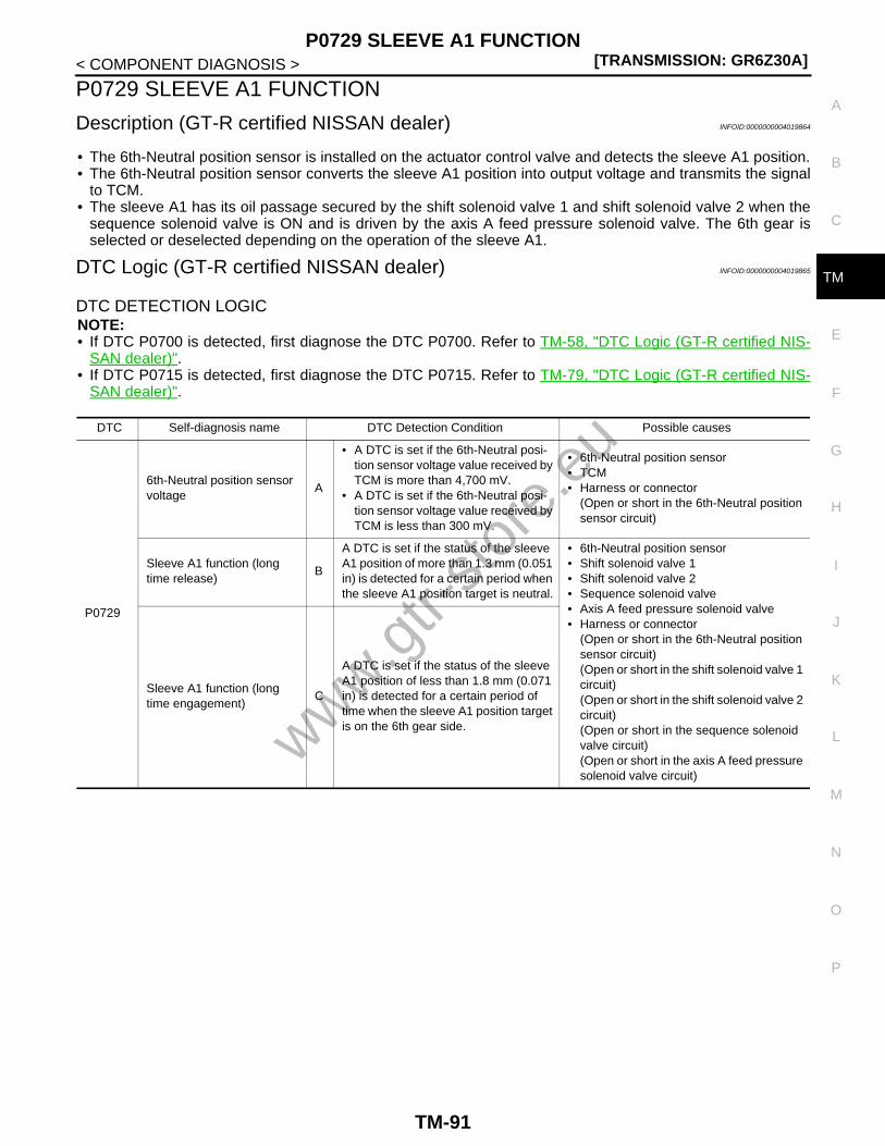
P0729 SLEEVE A1 FUNCTION[TRANSMISSION: GR6Z30A]
C
E
F
G
H
I
J
K
L
M
A
B
M
N
O
P
< COMPONENT DIAGNOSIS >
T
P0729 SLEEVE A1 FUNCTION
Description (GT-R certified NISSAN dealer) INFOID:0000000004019864
• The 6th-Neutral position sensor is installed on the actuator control valve and detects the sleeve A1 position.• The 6th-Neutral position sensor converts the sleeve A1 position into output voltage and transmits the signal
to TCM.• The sleeve A1 has its oil passage secured by the shift solenoid valve 1 and shift solenoid valve 2 when the
sequence solenoid valve is ON and is driven by the axis A feed pressure solenoid valve. The 6th gear isselected or deselected depending on the operation of the sleeve A1.
DTC Logic (GT-R certified NISSAN dealer) INFOID:0000000004019865
DTC DETECTION LOGICNOTE:• If DTC P0700 is detected, first diagnose the DTC P0700. Refer to TM-58, "DTC Logic (GT-R certified NIS-
SAN dealer)".• If DTC P0715 is detected, first diagnose the DTC P0715. Refer to TM-79, "DTC Logic (GT-R certified NIS-
SAN dealer)".
DTC Self-diagnosis name DTC Detection Condition Possible causes
P0729
6th-Neutral position sensor voltage
A
• A DTC is set if the 6th-Neutral posi-tion sensor voltage value received by TCM is more than 4,700 mV.
• A DTC is set if the 6th-Neutral posi-tion sensor voltage value received by TCM is less than 300 mV.
• 6th-Neutral position sensor• TCM• Harness or connector
(Open or short in the 6th-Neutral position sensor circuit)
Sleeve A1 function (long time release)
B
A DTC is set if the status of the sleeve A1 position of more than 1.3 mm (0.051 in) is detected for a certain period when the sleeve A1 position target is neutral.
• 6th-Neutral position sensor• Shift solenoid valve 1• Shift solenoid valve 2• Sequence solenoid valve• Axis A feed pressure solenoid valve• Harness or connector
(Open or short in the 6th-Neutral position sensor circuit)(Open or short in the shift solenoid valve 1 circuit)(Open or short in the shift solenoid valve 2 circuit)(Open or short in the sequence solenoid valve circuit)(Open or short in the axis A feed pressure solenoid valve circuit)
Sleeve A1 function (long time engagement)
C
A DTC is set if the status of the sleeve A1 position of less than 1.8 mm (0.071 in) is detected for a certain period of time when the sleeve A1 position target is on the 6th gear side.www.g
tr-sto
re.e
u
TM-91

[TRANSMISSION: GR6Z30A]P0729 SLEEVE A1 FUNCTION
< COMPONENT DIAGNOSIS >
*: A DTC is displayed when F or G in the DTC detection conditions is detected.
DTC CONFIRMATION PROCEDURECAUTION:• If CONSULT-III is not available, “TM-96, "Diagnosis Procedure (GT-R certified NISSAN dealer)"” must
be performed before starting “DTC CONFIRMATION PROCEDURE”.• If CONSULT-III is not available, never perform “DTC CONFIRMATION PROCEDURE” before complet-
ing the repair, which may cause secondary malfunction.• Be careful of the driving speed.
1.PREPARATION BEFORE OPERATION (PART 1)
Is CONSULT-III available?YES >> GO TO 2.NO >> GO TO 13.
2.PREPARATION BEFORE OPERATION (PART 2)
If another “DTC CONFIRMATION PROCEDURE” is performed just before the next test, turn the ignitionswitch OFF and wait for 10 seconds or more, then perform the next test.
P0729
Sleeve A1 function (poor neutral hold)
D
A DTC is set if the status of the sleeve A1 position of more than 1.7 mm (0.067 in) or less than −1.6 mm (−0.063 in) is detected for a certain period of time when the sleeve A1 position target is neutral with the sleeve A2 engaged in the 2nd or 4th gear.
• 6th-Neutral position sensor• Shift solenoid valve 1• Shift solenoid valve 2• Sequence solenoid valve• Harness or connector
(Open or short in the 6th-Neutral position sensor circuit)(Open or short in the shift solenoid valve 1 circuit)(Open or short in the shift solenoid valve 2 circuit)(Open or short in the sequence solenoid valve circuit)
Sleeve A1 function (poor en-gaged gear)
E
A DTC is set if the sleeve A1 position is 7.1 mm (0.28 in) or less and 1.7 mm (0.067 in) or more when the sleeve A1 position target is on the 6th gear side.
• Shift solenoid valve 1• Shift solenoid valve 2• Axis A feed pressure solenoid valve• Sleeve A1 related part• Harness or connector
(Open or short in the shift solenoid valve 1 circuit)(Open or short in the shift solenoid valve 2 circuit)(Open or short in the axis A feed pressure solenoid valve circuit)
Sleeve A1 function (gear re-
lease)*
F
A DTC is set if the status 1 or 2 below is detected with the sleeve A1 engaged in the 6th gear.1. The difference between the clutch
A speed calculated from the out-put shaft speed sensor value and clutch A speed sensor value is 1,000 rpm or more.
2. The difference between the clutch A speed calculated from the vehi-cle speed signal (meter) (CAN sig-nal) and clutch A speed sensor value is 1,000 rpm or more.
• Clutch A speed sensor• Sleeve A1 related part• Harness or connector
(Open or short in the clutch A speed sen-sor circuit)
GA DTC is set if the sleeve A1 and A2 po-sitions are not in 6th gear during driving in the 6th gear.
• Shift solenoid valve 1• Sleeve A1 related part• Harness or connector
(Open or short in the shift solenoid valve 1 circuit)
DTC Self-diagnosis name DTC Detection Condition Possible causes
www.gtr-
store
.eu
TM-92

P0729 SLEEVE A1 FUNCTION[TRANSMISSION: GR6Z30A]
C
E
F
G
H
I
J
K
L
M
A
B
M
N
O
P
< COMPONENT DIAGNOSIS >
T
>> GO TO 3.
3.PREPARATION BEFORE OPERATION (PART 3)
With CONSULT-III1. Turn the ignition switch ON.2. Select “FLUID TEMP” in “Data Monitor”.Is the oil temperature −20°C (−4°F) or more?YES >> GO TO 4.NO >> Warm up the transmission.
4.PREPARATION BEFORE OPERATION (PART 4)
With CONSULT-IIISelect “READ CLUTCH GEAR LEARNING DATA” in “Work support”.Is the “6-N learning experienced” YES?YES >> GO TO 5.NO >> Perform “CLUTCH GEAR LEARNING”.
5.CONFIRMATION BEFORE OPERATION (PART 1)
With CONSULT-IIISelect “SLEEVE A1 POSI” in “Data Monitor”.Is the numeral value of the “SLEEVE A1 POSI” in the range between −1.7 and 1.8 mm (−0.067 and 0.071 in)?YES >> GO TO 6.NO >> GO TO 7.
6.CONFIRMATION BEFORE OPERATION (PART 2)
With CONSULT-III1. Shift the shift lever to N position.2. Start the engine.3. Select “GEAR POSITION TEST” in “Work support”.4. Select “GEAR6”.
CAUTION:Never select “GEAR2”, “GEAR4” or “GEAR N”.
Does the sleeve A1 operate?YES >> GO TO 11.NO >> Go to TM-96, "Diagnosis Procedure (GT-R certified NISSAN dealer)".
7.PERFORM DTC CONFIRMATION PROCEDURE — DTC DETECTION CONDITION A
With CONSULT-III1. Turn ignition switch ON, and wait for 5 seconds or more.2. Check “Self Diagnostic Result” of “TRANSMISSION”.Is DTC P0729 detected?YES >> Go to TM-96, "Diagnosis Procedure (GT-R certified NISSAN dealer)".NO >> GO TO 8.
8.PERFORM DTC CONFIRMATION PROCEDURE — DTC DETECTION CONDITION B
With CONSULT-III1. Shift the shift lever to the N position.2. Start the engine and run at idle for 10 seconds or more.3. Check “Self Diagnostic Result” of “TRANSMISSION”.Is DTC P0729 or DTC P0795 detected?YES-1 (DTC P0729 is detected).>>Go to TM-96, "Diagnosis Procedure (GT-R certified NISSAN dealer)".YES-2 (DTC P0795 is detected).>>Go to TM-155, "DTC Logic (GT-R certified NISSAN dealer)".NO >> GO TO 9.
9.PERFORM DTC CONFIRMATION PROCEDURE
With CONSULT-III
www.gtr-
store
.eu
TM-93

[TRANSMISSION: GR6Z30A]P0729 SLEEVE A1 FUNCTION
< COMPONENT DIAGNOSIS >1. Shift the shift lever to the P position and run at idle for 1 minute or more.2. Check “Self Diagnostic Result” of “TRANSMISSION”.Is DTC P0795 or DTC P0797 detected?YES-1 (DTC P0795 is detected).>>Go to TM-155, "DTC Logic (GT-R certified NISSAN dealer)".YES-2 (DTC P0797 is detected).>>Go to TM-158, "DTC Logic (GT-R certified NISSAN dealer)".NO >> GO TO 10.
10.PERFORM DTC CONFIRMATION PROCEDURE — DTC DETECTION CONDITION D
With CONSULT-III1. Select “RANGE” and “GEAR” in “Data Monitor”.2. With the vehicle stationary, maintain the following conditions for 2 seconds or more.
3. Check “Self Diagnostic Result” of “TRANSMISSION”.Is DTC P0729 detected?YES >> Go to TM-96, "Diagnosis Procedure (GT-R certified NISSAN dealer)".NO >> GO TO 11.
11.PERFORM DTC CONFIRMATION PROCEDURE — DTC DETECTION CONDITION C AND E
With CONSULT-III1. Select “RANGE”, “GEAR” and “VEHICLE SPEED” in “Data Monitor”.2. Run the vehicle and maintain the following conditions for 10 seconds or more.
3. Check “Self Diagnostic Result” of “TRANSMISSION”.Is DTC P0729 detected?YES >> Go to TM-96, "Diagnosis Procedure (GT-R certified NISSAN dealer)".NO >> GO TO 12.
12.PERFORM DTC CONFIRMATION PROCEDURE — DTC DETECTION CONDITION F AND G
With CONSULT-III1. Select “RANGE”, “GEAR”, “ENGINE SPEED” and “VEHICLE SPEED” in “Data Monitor”.2. Run the vehicle and maintain the following conditions for 10 seconds or more.
3. Check “Self Diagnostic Result” of “TRANSMISSION”.Is DTC P0729 detected?YES >> Go to TM-96, "Diagnosis Procedure (GT-R certified NISSAN dealer)".NO >> INSPECTION END
13.PREPARATION BEFORE OPERATION (PART 2)
If another “DTC CONFIRMATION PROCEDURE” is performed just before the next test, turn the ignitionswitch OFF and wait for 10 seconds or more, then perform the next test.
>> GO TO 14.
14.PREPARATION BEFORE OPERATION (PART 3)
Without CONSULT-III1. Turn the ignition switch ON.2. Check “TRANS OIL TEMP” on multi-function display.
RANGE : M
GEAR : 1
RANGE : M
GEAR : 5
VEHICLE SPEED : 40 km/h (25 MPH) or more
RANGE : M
GEAR : 6
ENGINE SPEED : 1,000 rpm or more
VEHICLE SPEED : 40 km/h (25 MPH) or more
www.gtr-
store
.eu
TM-94

P0729 SLEEVE A1 FUNCTION[TRANSMISSION: GR6Z30A]
C
E
F
G
H
I
J
K
L
M
A
B
M
N
O
P
< COMPONENT DIAGNOSIS >
T
Is the oil temperature −20°C (−4°F) or more?YES >> GO TO 15.NO >> Warm up the transmission.
15.PERFORM DTC CONFIRMATION PROCEDURE — DTC DETECTION CONDITION A
Without CONSULT-III1. Turn ignition switch ON, and wait for 5 seconds or more.2. Check self-diagnosis.Is DTC P0729 detected?YES >> Go to TM-96, "Diagnosis Procedure (GT-R certified NISSAN dealer)".NO >> GO TO 16.
16.PERFORM DTC CONFIRMATION PROCEDURE — DTC DETECTION CONDITION B
Without CONSULT-III1. Shift the shift lever to the N position.2. Start the engine and run at idle for 10 seconds or more.3. Check self-diagnosis.Is DTC P0729 or DTC P0795 detected?YES-1 (DTC P0729 is detected).>>Go to TM-96, "Diagnosis Procedure (GT-R certified NISSAN dealer)".YES-2 (DTC P0795 is detected).>>Go to TM-155, "DTC Logic (GT-R certified NISSAN dealer)".NO >> GO TO 17.
17.PERFORM DTC CONFIRMATION PROCEDURE
Without CONSULT-III1. Shift the shift lever to the P position and run at idle for 1 minute or more.2. Check self-diagnosis.Is DTC P0795 or DTC P0797 detected?YES-1 (DTC P0795 is detected).>>Go to TM-155, "DTC Logic (GT-R certified NISSAN dealer)".YES-2 (DTC P0797 is detected).>>Go to TM-158, "DTC Logic (GT-R certified NISSAN dealer)".NO >> GO TO 18.
18.PERFORM DTC CONFIRMATION PROCEDURE — DTC DETECTION CONDITION D
Without CONSULT-III1. With the vehicle stationary, maintain the following conditions for 2 seconds or more.
2. Check self-diagnosis.Is DTC P0729 detected?YES >> Go to TM-96, "Diagnosis Procedure (GT-R certified NISSAN dealer)".NO >> GO TO 19.
19.PERFORM DTC CONFIRMATION PROCEDURE — DTC DETECTION CONDITION C AND E
Without CONSULT-III1. Run the vehicle and maintain the following conditions for 10 seconds or more.
2. Check self-diagnosis.Is DTC P0729 detected?YES >> Go to TM-96, "Diagnosis Procedure (GT-R certified NISSAN dealer)".NO >> GO TO 20.
20.PERFORM DTC CONFIRMATION PROCEDURE — DTC DETECTION CONDITION F AND G
Without CONSULT-III
Shift lever : M range
Gear : 1
Shift lever : M range
Gear : 5
Vehicle speed : 40 km/h (25 MPH) or more
www.gtr-
store
.eu
TM-95

[TRANSMISSION: GR6Z30A]P0729 SLEEVE A1 FUNCTION
< COMPONENT DIAGNOSIS >1. Run the vehicle and maintain the following conditions for 10 seconds or more.
2. Check self-diagnosis.Is DTC P0729 detected?YES >> Go to TM-96, "Diagnosis Procedure (GT-R certified NISSAN dealer)".NO >> INSPECTION END
Diagnosis Procedure (GT-R certified NISSAN dealer) INFOID:0000000004019866
1.CHECK SHIFT SOLENOID VALVE 1 CIRCUIT
Refer to TM-132, "Diagnosis Procedure (GT-R certified NISSAN dealer)".Is the inspection result normal?YES >> GO TO 2.NO >> Repair or replace damaged parts.
2.CHECK SHIFT SOLENOID VALVE 2 CIRCUIT
Refer to TM-135, "Diagnosis Procedure (GT-R certified NISSAN dealer)".Is the inspection result normal?YES >> GO TO 3.NO >> Repair or replace damaged parts.
3.CHECK SEQUENCE SOLENOID VALVE CIRCUIT
Refer to TM-145, "Diagnosis Procedure (GT-R certified NISSAN dealer)".Is the inspection result normal?YES >> GO TO 4.NO >> Repair or replace damaged parts.
4.CHECK AXIS A FEED PRESSURE SOLENOID VALVE CIRCUIT
Refer to TM-155, "Diagnosis Procedure (GT-R certified NISSAN dealer)".Is the inspection result normal?YES >> GO TO 5.NO >> Repair or replace damaged parts.
5.CHECK CLUTCH A SPEED SENSOR CIRCUIT
Refer to TM-80, "Diagnosis Procedure (GT-R certified NISSAN dealer)".Is the inspection result normal?YES >> GO TO 6.NO >> Repair or replace damaged parts.
6.CHECK GROUND CONNECTION
1. Turn ignition switch OFF.2. Check ground connections B31 and ground cable connections. Refer to “Ground Inspection” in XX-XX,
"*****".Is the inspection result normal?YES >> GO TO 7.NO >> Repair or replace damaged parts.
7.CHECK TCM OUTPUT SIGNAL CIRCUIT
Check voltage between TCM vehicle side harness connector terminals.
Shift lever : M range
Gear : 6
Engine speed : 1,000 rpm or more
Vehicle speed : 40 km/h (25 MPH) or more
www.gtr-
store
.eu
TM-96

P0729 SLEEVE A1 FUNCTION[TRANSMISSION: GR6Z30A]
C
E
F
G
H
I
J
K
L
M
A
B
M
N
O
P
< COMPONENT DIAGNOSIS >
T
Is the inspection result normal?YES >> GO TO 9.NO >> GO TO 8.
8.CHECK TCM POWER SUPPLY
Refer to TM-172, "Diagnosis Procedure (GT-R certified NISSAN dealer)".Is the inspection result normal?YES >> Replace TCM. Refer to TM-270, "Exploded View (GT-R certified NISSAN dealer)".NO >> Repair or replace damaged parts.
9.CHECK TCM INPUT SIGNAL CIRCUIT
1. Start engine.2. Check voltage between TCM vehicle side harness connector terminals.
Is the inspection result normal?YES >> GO TO 10.NO >> GO TO 11.
10.CHECK INTERMITTENT INCIDENT
Refer to XX-XX, "*****".
>> INSPECTION END
11.CHECK HARNESS BETWEEN TCM AND TRANSMISSION (4TH-NEUTRAL POSITION SENSOR)(PART 1)
1. Turn ignition switch OFF.2. Disconnect TCM harness connectors and transmission unit harness connectors.3. Check continuity between TCM vehicle side harness connector terminals and transmission unit vehicle
side harness connector terminals.
Is the inspection result normal?YES >> GO TO 12.NO >> Repair or replace damaged parts.
12.CHECK HARNESS BETWEEN TCM AND TRANSMISSION (4TH-NEUTRAL POSITION SENSOR)(PART 2)
Check continuity between TCM vehicle side harness connector terminals and ground.
TCM vehicle side harness connectorCondition Voltage (Approx.)
Connector Terminal
B46 74 4Ignition switch ON 5 V
Ignition switch OFF 0 V
TCM vehicle side harness connectorCondition Voltage (Approx.)
Connector Terminal
B46 70 4
Engine running
Shift lever: P, R, N position2.19 – 2.88 V
While driving
1st gear, 2nd gear, 3rd gear, 4th gear
5th gear, 6th gear(Other than M range, R mode)
0.68 – 1.76 V
TCM vehicle side harness connector Transmission unit vehicle side harness connectorContinuity
Connector Terminal Connector Terminal
B46
66
B49
25
Existed70 24
74 23
www.gtr-
store
.eu
TM-97

[TRANSMISSION: GR6Z30A]P0729 SLEEVE A1 FUNCTION
< COMPONENT DIAGNOSIS >
Is the inspection result normal?YES >> GO TO 13.NO >> Repair or replace damaged parts.
13.CHECK INTERMITTENT INCIDENT
Refer to XX-XX, "*****".Is the inspection result normal?YES >> Replace transmission assembly. Refer to TM-291, "Exploded View (GT-R certified NISSAN
dealer)".NO >> Repair or replace damaged parts.
TCM vehicle side harness connectorGround Continuity
Connector Terminal
B46
66
Ground Not existed70
74
www.gtr-
store
.eu
TM-98

P0731 SLEEVE B1 FUNCTION[TRANSMISSION: GR6Z30A]
C
E
F
G
H
I
J
K
L
M
A
B
M
N
O
P
< COMPONENT DIAGNOSIS >
T
P0731 SLEEVE B1 FUNCTION
Description (GT-R certified NISSAN dealer) INFOID:0000000004019871
• The 1st-Reverse position sensor 1 and 1st-Reverse position sensor 2 are installed on the actuator controlvalve and detect the sleeve B1 position.
• The 1st-Reverse position sensor 1 and 1st-Reverse position sensor 2 convert the sleeve B1 position intooutput voltage and transmit the signal to TCM.
• The sleeve B1 has its oil passage secured by the shift solenoid valve 3 and shift solenoid valve 2 when thesequence solenoid valve is OFF and is driven by the axis B feed pressure solenoid valve. The 1st gear andreverse gear are selected or deselected depending on the operation of the sleeve B1.
DTC Logic (GT-R certified NISSAN dealer) INFOID:0000000004019872
DTC DETECTION LOGICNOTE:• If DTC P0700 is detected, first diagnose the DTC P0700. Refer to TM-58, "DTC Logic (GT-R certified NIS-
SAN dealer)".• If DTC P2765 is detected, first diagnose the DTC P2765. Refer to TM-187, "DTC Logic (GT-R certified NIS-
SAN dealer)".
DTC Self-diagnosis name DTC detection condition Possible cause
P0731
1st-Reverse position sensor voltage
A
• A DTC is set if the 1st-Reverse posi-tion sensor 1 or 1st-Reverse position sensor 2 voltage value received by TCM is more than 4,700 mV.
• A DTC is set if the 1st-Reverse posi-tion sensor 1 or 1st-Reverse position sensor 2 voltage value received by TCM is less than 300 mV.
• 1st-Reverse position sensor 1• 1st-Reverse position sensor 2• TCM• Harness or connector
(Open or short in the 1st-Reverse position sensor 1 circuit)(Open or short in the 1st-Reverse position sensor 2 circuit)
Sleeve B1 function (long time release)
B
• A DTC is set if the status of the sleeve B1 position of more than 1.3 mm (0.051 in) is detected for a certain pe-riod of time when the sleeve B1 posi-tion target is neutral.
• A DTC is set if the status of the sleeve B1 position of less than −1.3 mm (−0.051 in) is detected for a certain pe-riod of time when the sleeve B1 posi-tion target is neutral.
• 1st-Reverse position sensor 1• Shift solenoid valve 3• Shift solenoid valve 4• Sequence solenoid valve• Axis B feed pressure solenoid valve• Harness or connector
(Open or short in the 1st-Reverse position sensor 1 circuit)(Open or short in the shift solenoid valve 3 circuit)(Open or short in the shift solenoid valve 4 circuit)(Open or short in the sequence solenoid valve circuit)(Open or short in the axis B feed pressure solenoid valve circuit)
Sleeve B1 function (long
time engagement)*1
C
A DTC is set if the status of the sleeve B1 position of less than 1.8 mm (0.071 in) is detected for a certain period of time when the sleeve B1 position target is on the 1st gear side.
D
A DTC is set if the status of the sleeve B1 position of more than 1.8 mm (0.071 in) is detected for a certain period of time when the sleeve B1 position target is on the reverse gear side.
www.gtr-
store
.eu
TM-99

[TRANSMISSION: GR6Z30A]P0731 SLEEVE B1 FUNCTION
< COMPONENT DIAGNOSIS >
• *1: A DTC is displayed when C or D in the DTC detection conditions is detected.
• *2: A DTC is displayed when F or G in the DTC detection conditions is detected.
• *3: A DTC is displayed when H, I, or J in the DTC detection conditions is detected.
DTC CONFIRMATION PROCEDURECAUTION:• If CONSULT-III is not available, “TM-104, "Diagnosis Procedure (GT-R certified NISSAN dealer)"”
must be performed before starting “DTC CONFIRMATION PROCEDURE”.• If CONSULT-III is not available, never perform “DTC CONFIRMATION PROCEDURE” before complet-
ing the repair, which may cause secondary malfunction.• Be careful of the driving speed.
P0731
Sleeve B1 function (poor neutral hold)
E
A DTC is set if the status of the sleeve B1 position of more than 1.7 mm (0.067 in) or less than −1.7 mm (−0.067 in) is detected for a certain period of time when the sleeve B1 position target is neutral with sleeve B2 engaged in the 3rd or 5th gear.
• 1st-Reverse position sensor 1• Shift solenoid valve 3• Shift solenoid valve 4• Sequence solenoid valve• Harness or connector
(Open or short in the 1st-Reverse position sensor 1 circuit)(Open or short in the shift solenoid valve 3 circuit)(Open or short in the shift solenoid valve 4 circuit)(Open or short in the sequence solenoid valve circuit)
Sleeve B1 function (poor
gear engagement)*2
F
A DTC is set if the sleeve B1 position is 7.1 mm (0.28 in) or less and 1.7 mm (0.067 in) or more when the sleeve B1 position target is on the 1st gear side.
• Shift solenoid valve 3• Shift solenoid valve 4• Axis B feed pressure solenoid valve• Sleeve B1 related part• Harness or connector
(Open or short in the shift solenoid valve 3 circuit)(Open or short in the shift solenoid valve 4 circuit)(Open or short in the sequence solenoid valve circuit)
G
A DTC is set if the sleeve B1 position is −1.7 mm (−0.067 in) or less and −7.1 mm (−0.28 in) or more when the sleeve B1 position target is on the reverse gear side.
Sleeve B1 function (gear re-
lease)*3
H
A DTC is set if the following statuses 1 and 2 are detected.1. The difference between the clutch
B speed calculated from the out-put shaft speed sensor value and clutch B speed sensor value is 1,000 rpm or more.
2. The difference between the clutch B speed calculated from the vehi-cle speed signal (meter) (CAN sig-nal) and clutch B speed sensor value is 1,000 rpm or more.
• Clutch B speed sensor• Sleeve B1 related part• Harness or connector
(Open or short in the clutch B speed sen-sor circuit)
IA DTC is set if the sleeve B1 and B2 po-sitions are not in 1st gear during driving in the 1st gear.
• Shift solenoid valve 3• Shift solenoid valve 4• Sleeve B1 related part• Harness or connector
(Open or short in the shift solenoid valve 3 circuit)(Open or short in the shift solenoid valve 4 circuit)
JA DTC is set if the sleeve B1 and B2 po-sitions are not in reverse during driving in the reverse gear.
1st-Reverse position sensor compatibility
K
A DTC is set if the difference between the sleeve B1 position calculated from the 1st-Reverse position sensor 1 value and the sleeve B1 position calculated from the 1st-Reverse position sensor 2 is 6 mm or more.
• 1st-Reverse position sensor 1• 1st-Reverse position sensor 2• Harness or connector
(Open or short in the 1st-Reverse position sensor 1 circuit)(Open or short in the 1st-Reverse position sensor 2 circuit)
DTC Self-diagnosis name DTC detection condition Possible cause
www.gtr-
store
.eu
TM-100

P0731 SLEEVE B1 FUNCTION[TRANSMISSION: GR6Z30A]
C
E
F
G
H
I
J
K
L
M
A
B
M
N
O
P
< COMPONENT DIAGNOSIS >
T
1.PREPARATION BEFORE OPERATION (PART 1)
Is CONSULT-III available?YES >> GO TO 2.NO >> GO TO 15.
2.PREPARATION BEFORE OPERATION (PART 2)
If another “DTC CONFIRMATION PROCEDURE” is performed just before the next test, turn the ignitionswitch OFF and wait for 10 seconds or more, then perform the next test.
>> GO TO 3.
3.PREPARATION BEFORE OPERATION (PART 3)
With CONSULT-III1. Turn the ignition switch ON.2. Select “FLUID TEMP” in “Data Monitor”.Is the oil temperature −20°C (−4°F) or more?YES >> GO TO 4.NO >> Warm up the transmission.
4.PREPARATION BEFORE OPERATION (PART 4)
With CONSULT-IIISelect “READ CLUTCH GEAR LEARNING DATA” in “Work support”.Is the “1-R learning experienced” YES?YES >> GO TO 5.NO >> Perform “CLUTCH GEAR LEARNING”.
5.CONFIRMATION BEFORE OPERATION (PART 1)
With CONSULT-IIISelect “SLEEVE B1 POSI 1” and “SLEEVE B1 POSI 2” in “Data Monitor”.Is the numeral value of the “SLEEVE B1 POSI 1” and “SLEEVE B1 POSI 2” in the range between −1.8 and 1.8mm (−0.071 and 0.071 in)?YES >> GO TO 6.NO >> GO TO 8.
6.CONFIRMATION BEFORE OPERATION (PART 2)
With CONSULT-III1. Shift the shift lever to the N position.2. Start the engine.3. Select “GEAR POSITION TEST” in “Work support”.4. Select “GEAR R”.
CAUTION:Never select “GEAR3”, “GEAR5” or “GEAR N”.
Does the sleeve B1 operate?YES >> GO TO 7.NO >> Go to TM-104, "Diagnosis Procedure (GT-R certified NISSAN dealer)".
7.CONFIRMATION BEFORE OPERATION (PART 3)
With CONSULT-III1. Select “GEAR POSITION TEST” in “Work support”.2. Select “GEAR1”.
CAUTION:Never select “GEAR3”, “GEAR5” or “GEAR N”.
Does the sleeve B1 operate?YES >> GO TO 12.NO >> Go to TM-104, "Diagnosis Procedure (GT-R certified NISSAN dealer)".
www.gtr-
store
.eu
TM-101
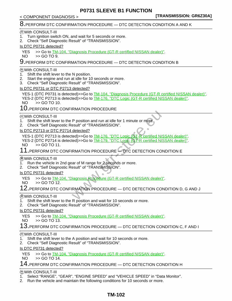
[TRANSMISSION: GR6Z30A]P0731 SLEEVE B1 FUNCTION
< COMPONENT DIAGNOSIS >
8.PERFORM DTC CONFIRMATION PROCEDURE — DTC DETECTION CONDITION A AND K
With CONSULT-III1. Turn ignition switch ON, and wait for 5 seconds or more.2. Check “Self Diagnostic Result” of “TRANSMISSION”.Is DTC P0731 detected?YES >> Go to TM-104, "Diagnosis Procedure (GT-R certified NISSAN dealer)".NO >> GO TO 9.
9.PERFORM DTC CONFIRMATION PROCEDURE — DTC DETECTION CONDITION B
With CONSULT-III1. Shift the shift lever to the N position.2. Start the engine and run at idle for 10 seconds or more.3. Check “Self Diagnostic Result” of “TRANSMISSION”.Is DTC P0731 or DTC P2713 detected?YES-1 (DTC P0731 is detected)>>Go to TM-104, "Diagnosis Procedure (GT-R certified NISSAN dealer)".YES-2 (DTC P2713 is detected)>>Go to TM-176, "DTC Logic (GT-R certified NISSAN dealer)".NO >> GO TO 10.
10.PERFORM DTC CONFIRMATION PROCEDURE
With CONSULT-III1. Shift the shift lever to the P position and run at idle for 1 minute or more.2. Check “Self Diagnostic Result” of “TRANSMISSION”.Is DTC P2713 or DTC P2714 detected?YES-1 (DTC P2713 is detected)>>Go to TM-176, "DTC Logic (GT-R certified NISSAN dealer)".YES-2 (DTC P2714 is detected)>>Go to TM-179, "DTC Logic (GT-R certified NISSAN dealer)".NO >> GO TO 11.
11.PERFORM DTC CONFIRMATION PROCEDURE — DTC DETECTION CONDITION E
With CONSULT-III1. Run the vehicle in 2nd gear of M range for 2 seconds or more.2. Check “Self Diagnostic Result” of “TRANSMISSION”.Is DTC P0731 detected?YES >> Go to TM-104, "Diagnosis Procedure (GT-R certified NISSAN dealer)".NO >> GO TO 12.
12.PERFORM DTC CONFIRMATION PROCEDURE — DTC DETECTION CONDITION D, G AND J
With CONSULT-III1. Shift the shift lever to the R position and wait for 10 seconds or more.2. Check “Self Diagnostic Result” of “TRANSMISSION”.Is DTC P0731 detected?YES >> Go to TM-104, "Diagnosis Procedure (GT-R certified NISSAN dealer)".NO >> GO TO 13.
13.PERFORM DTC CONFIRMATION PROCEDURE — DTC DETECTION CONDITION C, F AND I
With CONSULT-III1. Shift the shift lever to the A position and wait for 10 seconds or more.2. Check “Self Diagnostic Result” of “TRANSMISSION”.Is DTC P0731 detected?YES >> Go to TM-104, "Diagnosis Procedure (GT-R certified NISSAN dealer)".NO >> GO TO 14.
14.PERFORM DTC CONFIRMATION PROCEDURE — DTC DETECTION CONDITION H
With CONSULT-III1. Select “RANGE”, “GEAR”, “ENGINE SPEED” and “VEHICLE SPEED” in “Data Monitor”.2. Run the vehicle and maintain the following conditions for 10 seconds or more.
www.gtr-
store
.eu
TM-102

P0731 SLEEVE B1 FUNCTION[TRANSMISSION: GR6Z30A]
C
E
F
G
H
I
J
K
L
M
A
B
M
N
O
P
< COMPONENT DIAGNOSIS >
T
3. Check “Self Diagnostic Result” of “TRANSMISSION”.Is DTC P0731 detected?YES >> Go to TM-104, "Diagnosis Procedure (GT-R certified NISSAN dealer)".NO >> INSPECTION END.
15.PREPARATION BEFORE OPERATION (PART 2)
If another “DTC CONFIRMATION PROCEDURE” is performed just before the next test, turn the ignitionswitch OFF and wait for 10 seconds or more, then perform the next test.
>> GO TO 16.
16.PREPARATION BEFORE OPERATION (PART 3)
Without CONSULT-III1. Turn the ignition switch ON.2. Check “TRANS OIL TEMP” on multi-function display.Is the oil temperature −20°C (−4°F) or more?YES >> GO TO 17.NO >> Warm up the transmission.
17.PERFORM DTC CONFIRMATION PROCEDURE — DTC DETECTION CONDITION A AND K
Without CONSULT-III1. Turn ignition switch ON, and wait for 5 seconds or more.2. Check self-diagnosis.Is DTC P0731 detected?YES >> Go to TM-104, "Diagnosis Procedure (GT-R certified NISSAN dealer)".NO >> GO TO 18.
18.PERFORM DTC CONFIRMATION PROCEDURE — DTC DETECTION CONDITION B
Without CONSULT-III1. Shift the shift lever to the N position.2. Start the engine and run at idle for 10 seconds or more.3. Check self-diagnosis.Is DTC P0731 or DTC P2713 detected?YES-1 (DTC P0731 is detected)>>Go to TM-104, "Diagnosis Procedure (GT-R certified NISSAN dealer)".YES-2 (DTC P2713 is detected)>>Go to TM-176, "DTC Logic (GT-R certified NISSAN dealer)".NO >> GO TO 19.
19.PERFORM DTC CONFIRMATION PROCEDURE
Without CONSULT-III1. Shift the shift lever to the P position and run at idle for 1 minute or more.2. Check self-diagnosis.Is DTC P2713 or DTC P2714 detected?YES-1 (DTC P2713 is detected)>>Go to TM-176, "DTC Logic (GT-R certified NISSAN dealer)".YES-2 (DTC P2714 is detected)>>Go to TM-179, "DTC Logic (GT-R certified NISSAN dealer)".NO >> GO TO 20.
20.PERFORM DTC CONFIRMATION PROCEDURE — DTC DETECTION CONDITION E
Without CONSULT-III1. Run the vehicle in 2nd gear of M range for 2 seconds or more.2. Check self-diagnosis.Is DTC P0731 detected?
RANGE : M
GEAR : 1
ENGINE SPEED : 4,500 rpm or more
VEHICLE SPEED : 40 km/h (25 MPH) or more
www.gtr-
store
.eu
TM-103

[TRANSMISSION: GR6Z30A]P0731 SLEEVE B1 FUNCTION
< COMPONENT DIAGNOSIS >YES >> Go to TM-104, "Diagnosis Procedure (GT-R certified NISSAN dealer)".NO >> GO TO 21.
21.PERFORM DTC CONFIRMATION PROCEDURE — DTC DETECTION CONDITION D, G AND J
Without CONSULT-III1. Shift the shift lever to the R position and wait for 10 seconds or more.2. Check self-diagnosis.Is DTC P0731 detected?YES >> Go to TM-104, "Diagnosis Procedure (GT-R certified NISSAN dealer)".NO >> GO TO 22.
22.PERFORM DTC CONFIRMATION PROCEDURE — DTC DETECTION CONDITION C, F AND I
Without CONSULT-III1. Shift the shift lever to the A position and wait for 10 seconds or more.2. Check self-diagnosis.Is DTC P0731 detected?YES >> Go to TM-104, "Diagnosis Procedure (GT-R certified NISSAN dealer)".NO >> GO TO 23.
23.PERFORM DTC CONFIRMATION PROCEDURE — DTC DETECTION CONDITION H
Without CONSULT-III1. Run the vehicle and maintain the following conditions for 10 seconds or more.
2. Check self-diagnosis.Is DTC P0731 detected?YES >> Go to TM-104, "Diagnosis Procedure (GT-R certified NISSAN dealer)".NO >> INSPECTION END.
Diagnosis Procedure (GT-R certified NISSAN dealer) INFOID:0000000004019873
1.CHECK SHIFT SOLENOID VALVE 3 CIRCUIT
Refer to TM-138, "Diagnosis Procedure (GT-R certified NISSAN dealer)".Is the inspection result normal?YES >> GO TO 2.NO >> Repair or replace damaged parts.
2.CHECK SHIFT SOLENOID VALVE 4 CIRCUIT
Refer to TM-141, "Diagnosis Procedure (GT-R certified NISSAN dealer)".Is the inspection result normal?YES >> GO TO 3.NO >> Repair or replace damaged parts.
3.CHECK SEQUENCE SOLENOID VALVE CIRCUIT
Refer to TM-145, "Diagnosis Procedure (GT-R certified NISSAN dealer)".Is the inspection result normal?YES >> GO TO 4.NO >> Repair or replace damaged parts.
4.CHECK AXIS B FEED PRESSURE SOLENOID VALVE CIRCUIT
Refer to TM-176, "Diagnosis Procedure (GT-R certified NISSAN dealer)".Is the inspection result normal?YES >> GO TO 5.
Shift lever : M range
Gear : 1
Engine speed : 4,500 rpm or more
Vehicle speed : 40 km/h (25 MPH) or more
www.gtr-
store
.eu
TM-104

P0731 SLEEVE B1 FUNCTION[TRANSMISSION: GR6Z30A]
C
E
F
G
H
I
J
K
L
M
A
B
M
N
O
P
< COMPONENT DIAGNOSIS >
T
NO >> Repair or replace damaged parts.
5.CHECK CLUTCH B SPEED SENSOR CIRCUIT
Refer to TM-176, "Diagnosis Procedure (GT-R certified NISSAN dealer)".Is the inspection result normal?YES >> GO TO 6.NO >> Repair or replace damaged parts.
6.CHECK GROUND CONNECTION
1. Turn ignition switch OFF.2. Check ground connections B31 and ground cable connections. Refer to “Ground Inspection” in XX-XX,
"*****".Is the inspection result normal?YES >> GO TO 7.NO >> Repair or replace damaged parts.
7.CHECK TCM OUTPUT SIGNAL CIRCUIT
Check voltage between TCM vehicle side harness connector terminals.
Is the inspection result normal?YES >> GO TO 9.NO >> GO TO 8.
8.CHECK TCM POWER SUPPLY
Refer to TM-172, "Diagnosis Procedure (GT-R certified NISSAN dealer)".Is the inspection result normal?YES >> Replace TCM. Refer to TM-270, "Exploded View (GT-R certified NISSAN dealer)".NO >> Repair or replace damaged parts.
9.CHECK TCM INPUT SIGNAL CIRCUIT (1ST-REVERSE POSITION SENSOR 1)
1. Start engine.2. Check voltage between TCM vehicle side harness connector terminals.
Is the inspection result normal?YES >> GO TO 10.NO >> GO TO 11.
10.CHECK INTERMITTENT INCIDENT
Refer to XX-XX, "*****".
TCM vehicle side harness connectorCondition Voltage (Approx.)
Connector Terminal
B46
71
4
Ignition switch ON 5 V
Ignition switch OFF 0 V
75Ignition switch ON 5 V
Ignition switch OFF 0 V
TCM vehicle side harness connectorCondition Voltage (Approx.)
Connector Terminal
B46 67 4
Engine running
Shift lever: P, N position 2.19 – 2.88 V
Shift lever: R position 0.68 – 1.76 V
While driving
1st gear 3.34 – 4.41 V
2nd gear, 3rd gear, 4th gear, 5th gear, 6th gear(Other than M range, R mode)
2.19 – 2.88 V
www.gtr-
store
.eu
TM-105

[TRANSMISSION: GR6Z30A]P0731 SLEEVE B1 FUNCTION
< COMPONENT DIAGNOSIS >>> INSPECTION END
11.CHECK HARNESS BETWEEN TCM AND TRANSMISSION (1ST-REVERSE POSITION SENSOR 1)(PART 1)
1. Turn ignition switch OFF.2. Disconnect TCM harness connectors and transmission unit harness connectors.3. Check continuity between TCM vehicle side harness connector terminals and transmission unit vehicle
side harness connector terminals.
Is the inspection result normal?YES >> GO TO 12.NO >> Repair or replace damaged parts.
12.CHECK HARNESS BETWEEN TCM AND TRANSMISSION (1ST-REVERSE POSITION SENSOR 1)(PART 2)
Check continuity between TCM vehicle side harness connector terminals and ground.
Is the inspection result normal?YES >> GO TO 13.NO >> Repair or replace damaged parts.
13.CHECK TCM INPUT SIGNAL CIRCUIT (1ST-REVERSE POSITION SENSOR 2)
1. Connect TCM harness connectors and transmission unit harness connectors.2. Start engine.3. Check voltage between TCM vehicle side harness connector terminals.
Is the inspection result normal?YES >> GO TO 10.NO >> GO TO 14.
14.CHECK HARNESS BETWEEN TCM AND TRANSMISSION (1ST-REVERSE POSITION SENSOR 2)(PART 1)
1. Turn ignition switch OFF.2. Disconnect TCM harness connectors and transmission unit harness connectors.3. Check continuity between TCM vehicle side harness connector terminals and transmission unit vehicle
side harness connector terminals.
TCM vehicle side harness connector Transmission unit vehicle side harness connectorContinuity
Connector Terminal Connector Terminal
B46
67
B49
4
Existed71 3
94 5
TCM vehicle side harness connectorGround Continuity
Connector Terminal
B46
67
Ground Not existed71
94
TCM vehicle side harness connectorCondition Voltage (Approx.)
Connector Terminal
B46 79 4
Engine running
Shift lever: P, N position 2.19 – 2.88 V
Shift lever: R position 3.34 – 4.41 V
While driving
1st gear 0.68 – 1.76 V
2nd gear, 3rd gear, 4th gear, 5th gear, 6th gear(Other than M range, R mode)
2.19 – 2.88 V
www.gtr-
store
.eu
TM-106

P0731 SLEEVE B1 FUNCTION[TRANSMISSION: GR6Z30A]
C
E
F
G
H
I
J
K
L
M
A
B
M
N
O
P
< COMPONENT DIAGNOSIS >
T
Is the inspection result normal?YES >> GO TO 15.NO >> Repair or replace damaged parts.
15.CHECK HARNESS BETWEEN TCM AND TRANSMISSION (1ST-REVERSE POSITION SENSOR 2)(PART 2)
Check continuity between TCM vehicle side harness connector terminals and ground.
Is the inspection result normal?YES >> GO TO 16.NO >> Repair or replace damaged parts.
16.CHECK INTERMITTENT INCIDENT
Refer to XX-XX, "*****".Is the inspection result normal?YES >> Replace transmission assembly. Refer to TM-291, "Exploded View (GT-R certified NISSAN
dealer)".NO >> Repair or replace damaged parts.
TCM vehicle side harness connector Transmission unit vehicle side harness connectorContinuity
Connector Terminal Connector Terminal
B46
69
B49
32
Existed75 30
79 31
TCM vehicle side harness connectorGround Continuity
Connector Terminal
B46
69
Ground Not existed75
79
www.gtr-
store
.eu
TM-107

[TRANSMISSION: GR6Z30A]P0732 SLEEVE A2 FUNCTION
< COMPONENT DIAGNOSIS >
P0732 SLEEVE A2 FUNCTION
Description (GT-R certified NISSAN dealer) INFOID:0000000004019878
• The 2nd-4th position sensor is installed on the actuator control valve and detects the sleeve A2 position.• The 2nd-4th position sensor converts the sleeve A2 position into output voltage and transmits the signal to
TCM.• The sleeve A2 has its oil passage secured by the shift solenoid valve 1 and shift solenoid valve 2 when the
sequence solenoid valve is OFF and is driven by the axis A feed pressure solenoid valve. The 2nd gear and4th gear are selected or deselected depending on the operation of the sleeve A2.
DTC Logic (GT-R certified NISSAN dealer) INFOID:0000000004019879
DTC DETECTION LOGICNOTE:• If DTC P0700 is detected, first diagnose the DTC P0700. Refer to TM-58, "DTC Logic (GT-R certified NIS-
SAN dealer)".• If DTC P0715 is detected, first diagnose the DTC P0715. Refer to TM-79, "DTC Logic (GT-R certified NIS-
SAN dealer)".
DTC Self-diagnosis name DTC detection condition Possible cause
P0732
2nd-4th position sensor volt-age
A
• A DTC is set if the 2nd-4th position sensor voltage value received by TCM is more than 4,700 mV.
• A DTC is set if the 2nd-4th position sensor voltage value received by TCM is less than 300 mV.
• 2nd-4th position sensor• TCM• Harness or connector
(Open or short in the 2nd-4th position sen-sor circuit)
Sleeve A2 function (long time release)
B
• A DTC is set if the status of the sleeve A2 position of more than 1.3 mm (0.051 in) is detected for a certain pe-riod of time when the sleeve A2 posi-tion target is neutral.
• A DTC is set if the status of the sleeve A2 position of less than −1.3 mm (−0.051 in) is detected for a certain pe-riod of time when the sleeve A2 posi-tion target is neutral.
• 2nd-4th position sensor• Shift solenoid valve 1• Shift solenoid valve 2• Sequence solenoid valve• Harness or connector
(Open or short in the 2nd-4th position sen-sor circuit)(Open or short in the shift solenoid valve 1 circuit)(Open or short in the shift solenoid valve 2 circuit)(Open or short in the sequence solenoid valve circuit)
Sleeve A2 function (long
time engagement)*1
C
A DTC is set if the status of the sleeve A2 position of less than 1.8 mm (0.071 in) is detected for a certain period of time when the sleeve A2 position target is on the 2nd gear side.
D
A DTC is set if the status of the sleeve A2 position of more than −1.8 mm (−0.071 in) is detected for a certain period of time when the sleeve A2 position tar-get is on the 4th gear side.
www.gtr-
store
.eu
TM-108

P0732 SLEEVE A2 FUNCTION[TRANSMISSION: GR6Z30A]
C
E
F
G
H
I
J
K
L
M
A
B
M
N
O
P
< COMPONENT DIAGNOSIS >
T
• *1: A DTC is displayed when C or D in the DTC detection conditions is detected.
• *2: A DTC is displayed when F or G in the DTC detection conditions is detected.
• *3: A DTC is displayed when H, I, or J in the DTC detection conditions is detected.
DTC CONFIRMATION PROCEDURECAUTION:• If CONSULT-III is not available, “TM-114, "Diagnosis Procedure (GT-R certified NISSAN dealer)"”
must be performed before starting “DTC CONFIRMATION PROCEDURE”.• If CONSULT-III is not available, never perform “DTC CONFIRMATION PROCEDURE” before complet-
ing the repair, which may cause secondary malfunction.• Be careful of the driving speed.
1.PREPARATION BEFORE OPERATION (PART 1)
Is CONSULT-III available?YES >> GO TO 2.NO >> GO TO 16.
P0732
Sleeve A2 function (poor neutral hold)
E
A DTC is set if the status of the sleeve A2 position of more than 1.7 mm (0.067 in) or less than −1.7 mm (−0.067 in) is detected for a certain period of time when the sleeve A2 position target is neutral with the sleeve A1 engaged in the 6th gear.
• 2nd-4th position sensor• Shift solenoid valve 1• Shift solenoid valve 2• Sequence solenoid valve• Harness or connector
(Open or short in the 2nd-4th position sen-sor circuit)(Open or short in the shift solenoid valve 1 circuit)(Open or short in the shift solenoid valve 2 circuit)(Open or short in the sequence solenoid valve circuit)
Sleeve A2 function (poor
gear engagement)*2
F
A DTC is set if the sleeve A2 position is 7.0 mm (0.276 in) or less and 1.7 mm (0.067 in) or more when the sleeve A2 position target is on the 2nd gear side.
• Shift solenoid valve 1• Shift solenoid valve 2• Axis A feed pressure solenoid valve• Sleeve A2 related part• Harness or connector
(Open or short in the shift solenoid valve 1 circuit)(Open or short in the shift solenoid valve 2 circuit)(Open or short in the axis A feed pressure solenoid valve circuit)
G
A DTC is set if the sleeve A2 position is −1.7 mm (−0.067 in) or less and −7.1 mm (−0.28 in) or more when the sleeve A2 position target is on the 4th gear side.
Sleeve A2 function (gear re-
lease)*3
H
A DTC is set if the following statuses 1 and 2 are detected.1. The difference between the clutch
A speed calculated from the out-put shaft speed sensor value and clutch A speed sensor value is 1,000 rpm or more.
2. The difference between the clutch A speed calculated from the vehi-cle speed signal (meter) (CAN sig-nal) and clutch A speed sensor value is 1,000 rpm or more.
• Clutch A speed sensor• Sleeve A2 related part• Harness or connector
(Open or short in the clutch A speed sen-sor circuit)
IA DTC is set if the sleeve A1 and A2 po-sitions are not in 2nd gear during driving in the 2nd gear.
• Shift solenoid valve 1• Shift solenoid valve 2• Sleeve A2 related part• Harness or connector
(Open or short in the shift solenoid valve 1 circuit)(Open or short in the shift solenoid valve 2 circuit)
JA DTC is set if the sleeve A1 and A2 po-sitions are not in 4th gear during driving in the 4th gear.
DTC Self-diagnosis name DTC detection condition Possible cause
www.gtr-
store
.eu
TM-109

[TRANSMISSION: GR6Z30A]P0732 SLEEVE A2 FUNCTION
< COMPONENT DIAGNOSIS >
2.PREPARATION BEFORE OPERATION (PART 1)
If another “DTC CONFIRMATION PROCEDURE” is performed just before the next test, turn the ignitionswitch OFF and wait for 10 seconds or more, then perform the next test.
>> GO TO 3.
3.PREPARATION BEFORE OPERATION (PART 2)
With CONSULT-III1. Turn the ignition switch ON.2. Select “FLUID TEMP” in “Data Monitor”.Is the oil temperature −20°C (−4°F) or more?YES >> GO TO 4.NO >> Warm up the transmission.
4.PREPARATION BEFORE OPERATION (PART 3)
With CONSULT-IIISelect “READ CLUTCH GEAR LEARNING DATA” in “Work support”.Is the “2-4 learning experienced” YES?YES >> GO TO 5.NO >> Perform “CLUTCH GEAR LEARNING”.
5.CONFIRMATION BEFORE OPERATION (PART 1)
With CONSULT-IIISelect “SLEEVE A2 POSI” in “Data Monitor”.Is the numeral value of the “SLEEVE A2 POSI” in the range between −1.8 and 1.8 mm (−0.071 and 0.071 in)?YES >> GO TO 6.NO >> GO TO 8.
6.CONFIRMATION BEFORE OPERATION (PART 2)
With CONSULT-III1. Shift the shift lever to the N position.2. Start the engine.3. Select “GEAR POSITION TEST” in “Work support”.4. Select “GEAR2”.
CAUTION:Never select “GEAR6” or “GEAR N”.
Does the sleeve A2 operate?YES >> GO TO 7.NO >> Go to TM-114, "Diagnosis Procedure (GT-R certified NISSAN dealer)".
7.CONFIRMATION BEFORE OPERATION (PART 3)
With CONSULT-III1. Select “GEAR POSITION TEST” in “Work support”.2. Select “GEAR4”.
CAUTION:Never select “GEAR6” or “GEAR N”.
Does the sleeve A2 operate?YES >> GO TO 12.NO >> Go to TM-114, "Diagnosis Procedure (GT-R certified NISSAN dealer)".
8.PERFORM DTC CONFIRMATION PROCEDURE — DTC DETECTION CONDITION A
With CONSULT-III1. Turn ignition switch ON, and wait for 5 seconds or more.2. Check “Self Diagnostic Result” of “TRANSMISSION”.Is DTC P0732 detected?YES >> Go to TM-114, "Diagnosis Procedure (GT-R certified NISSAN dealer)".
www.gtr-
store
.eu
TM-110

P0732 SLEEVE A2 FUNCTION[TRANSMISSION: GR6Z30A]
C
E
F
G
H
I
J
K
L
M
A
B
M
N
O
P
< COMPONENT DIAGNOSIS >
T
NO >> GO TO 9.
9.PERFORM DTC CONFIRMATION PROCEDURE — DTC DETECTION CONDITION B
With CONSULT-III1. Shift the shift lever to the N position.2. Start the engine and run at idle for 10 seconds or more.3. Check “Self Diagnostic Result” of “TRANSMISSION”.Is DTC P0732 or DTC P0795 detected?YES-1 (DTC P0732 is detected)>>Go to TM-114, "Diagnosis Procedure (GT-R certified NISSAN dealer)".YES-2 (DTC P0795 is detected)>>Go to TM-155, "Diagnosis Procedure (GT-R certified NISSAN dealer)".NO >> GO TO 10.
10.PERFORM DTC CONFIRMATION PROCEDURE
With CONSULT-III1. Shift the shift lever to the P position and run at idle for 1 minute or more.2. Check “Self Diagnostic Result” of “TRANSMISSION”.Is DTC P0795 or DTC P0797 detected?YES-1 (DTC P0795 is detected)>>Go to TM-155, "Diagnosis Procedure (GT-R certified NISSAN dealer)".YES-2 (DTC P0797 is detected)>>Go to TM-158, "Diagnosis Procedure (GT-R certified NISSAN dealer)".NO >> GO TO 11.
11.PERFORM DTC CONFIRMATION PROCEDURE — DTC DETECTION CONDITION E
With CONSULT-III1. Run the vehicle in 5th gear of M range for 2 seconds or more.2. Check “Self Diagnostic Result” of “TRANSMISSION”.Is DTC P0732 detected?YES >> Go to TM-114, "Diagnosis Procedure (GT-R certified NISSAN dealer)".NO >> GO TO 12.
12.PERFORM DTC CONFIRMATION PROCEDURE — DTC DETECTION CONDITION C AND F
With CONSULT-III1. Select “RANGE”, “GEAR” and “VEHICLE SPEED” in “Data Monitor”.2. Run the vehicle and maintain the following conditions for 10 second.
3. Check “Self Diagnostic Result” of “TRANSMISSION”.Is DTC P0732 detected?YES >> Go to TM-114, "Diagnosis Procedure (GT-R certified NISSAN dealer)".NO >> GO TO 13.
13.PERFORM DTC CONFIRMATION PROCEDURE — DTC DETECTION CONDITION H AND I
With CONSULT-III1. Select “RANGE”, “GEAR”, “ENGINE SPEED” and “VEHICLE SPEED” in “Data Monitor”.2. Run the vehicle and maintain the following conditions for 10 seconds or more.
3. Check “Self Diagnostic Result” of “TRANSMISSION”.Is DTC P0732 detected?YES >> Go to TM-114, "Diagnosis Procedure (GT-R certified NISSAN dealer)".NO >> GO TO 14.
RANGE : M
GEAR : 1
ENGINE SPEED : 40 km/h (25 MPH) or more
RANGE : M
GEAR : 2
ENGINE SPEED : 3,000 rpm or more
VEHICLE SPEED : 40 km/h (25 MPH) or more
www.gtr-
store
.eu
TM-111

[TRANSMISSION: GR6Z30A]P0732 SLEEVE A2 FUNCTION
< COMPONENT DIAGNOSIS >
14.PERFORM DTC CONFIRMATION PROCEDURE — DTC DETECTION CONDITION D AND G
With CONSULT-III1. Select “RANGE”, “GEAR”, and “VEHICLE SPEED” in “Data Monitor”.2. Run the vehicle and maintain the following conditions for 10 seconds or more.
3. Check “Self Diagnostic Result” of “TRANSMISSION”.Is DTC P0732 detected?YES >> Go to TM-114, "Diagnosis Procedure (GT-R certified NISSAN dealer)".NO >> GO TO 15.
15.PERFORM DTC CONFIRMATION PROCEDURE — DTC DETECTION CONDITION J
With CONSULT-III1. Select “RANGE”, “GEAR” and “VEHICLE SPEED” in “Data Monitor”.2. Run the vehicle and maintain the following conditions for 10 seconds or more.
3. Check “Self Diagnostic Result” of “TRANSMISSION”.Is DTC P0732 detected?YES >> Go to TM-114, "Diagnosis Procedure (GT-R certified NISSAN dealer)".NO >> INSPECTION END
16.PREPARATION BEFORE OPERATION (PART 2)
Without CONSULT-III1. Turn the ignition switch ON.2. Check "TRANS OIL TEMP" on multi-function display.Is the oil temperature −20°C (−4°F) or more?YES >> GO TO 17.NO >> Warm up the transmission.
17.PERFORM DTC CONFIRMATION PROCEDURE — DTC DETECTION CONDITION A
Without CONSULT-III1. Turn ignition switch ON, and wait for 5 seconds or more.2. Check self-diagnosis.Is DTC P0732 detected?YES >> Go to TM-114, "Diagnosis Procedure (GT-R certified NISSAN dealer)".NO >> GO TO 18.
18.PERFORM DTC CONFIRMATION PROCEDURE — DTC DETECTION CONDITION B
Without CONSULT-III1. Shift the shift lever to the N position.2. Start the engine and run at idle for 10 seconds or more.3. Check self-diagnosis.Is DTC P0732 or DTC P0795 detected?YES-1 (DTC P0732 is detected)>>Go to TM-114, "Diagnosis Procedure (GT-R certified NISSAN dealer)".YES-2 (DTC P0795 is detected)>>Go to TM-155, "Diagnosis Procedure (GT-R certified NISSAN dealer)".NO >> GO TO 19.
19.PERFORM DTC CONFIRMATION PROCEDURE
Without CONSULT-III1. Shift the shift lever to the P position and run at idle for 1 minute or more.
RANGE : M
GEAR : 3
VEHICLE SPEED : 40 km/h (25 MPH) or more
RANGE : M
GEAR : 4
VEHICLE SPEED : 40 km/h (25 MPH) or more
www.gtr-
store
.eu
TM-112

P0732 SLEEVE A2 FUNCTION[TRANSMISSION: GR6Z30A]
C
E
F
G
H
I
J
K
L
M
A
B
M
N
O
P
< COMPONENT DIAGNOSIS >
T
2. Check self-diagnosis.Is DTC P0795 or DTC P0797 detected?YES-1 (DTC P0795 is detected)>>Go to TM-155, "Diagnosis Procedure (GT-R certified NISSAN dealer)".YES-2 (DTC P0797 is detected)>>Go to TM-158, "Diagnosis Procedure (GT-R certified NISSAN dealer)".NO >> GO TO 20.
20.PERFORM DTC CONFIRMATION PROCEDURE — DTC DETECTION CONDITION E
Without CONSULT-III1. Run the vehicle in 5th gear of M range for 2 seconds or more.2. Check self-diagnosis.Is DTC P0732 detected?YES >> Go to TM-114, "Diagnosis Procedure (GT-R certified NISSAN dealer)".NO >> GO TO 21.
21.PERFORM DTC CONFIRMATION PROCEDURE — DTC DETECTION CONDITION C AND F
Without CONSULT-III1. Run the vehicle and maintain the following conditions for 10 second.
2. Check self-diagnosis.Is DTC P0732 detected?YES >> Go to TM-114, "Diagnosis Procedure (GT-R certified NISSAN dealer)".NO >> GO TO 22.
22.PERFORM DTC CONFIRMATION PROCEDURE — DTC DETECTION CONDITION H AND I
Without CONSULT-III1. Run the vehicle and maintain the following conditions for 10 seconds or more.
2. Check self-diagnosis.Is DTC P0732 detected?YES >> Go to TM-114, "Diagnosis Procedure (GT-R certified NISSAN dealer)".NO >> GO TO 23.
23.PERFORM DTC CONFIRMATION PROCEDURE — DTC DETECTION CONDITION D AND G
Without CONSULT-III1. Run the vehicle and maintain the following conditions for 10 seconds or more.
2. Check self-diagnosis.Is DTC P0732 detected?YES >> Go to TM-114, "Diagnosis Procedure (GT-R certified NISSAN dealer)".NO >> GO TO 24.
24.PERFORM DTC CONFIRMATION PROCEDURE — DTC DETECTION CONDITION J
Without CONSULT-III1. Run the vehicle and maintain the following conditions for 10 seconds or more.
Shift lever : M range
Gear : 1
Engine speed : 40 km/h (25 MPH) or more
Shift lever : M range
Gear : 2
Engine speed : 3,000 rpm or more
Vehicle speed : 40 km/h (25 MPH) or more
Shift lever : M range
Gear : 3
Vehicle speed : 40 km/h (25 MPH) or more
www.gtr-
store
.eu
TM-113

[TRANSMISSION: GR6Z30A]P0732 SLEEVE A2 FUNCTION
< COMPONENT DIAGNOSIS >
2. Check self-diagnosis.Is DTC P0732 detected?YES >> Go to TM-114, "Diagnosis Procedure (GT-R certified NISSAN dealer)".NO >> INSPECTION END
Diagnosis Procedure (GT-R certified NISSAN dealer) INFOID:0000000004019880
1.CHECK SHIFT SOLENOID VALVE 1 CIRCUIT
Refer to TM-132, "Diagnosis Procedure (GT-R certified NISSAN dealer)".Is the inspection result normal?YES >> GO TO 2.NO >> Repair or replace damaged parts.
2.CHECK SHIFT SOLENOID VALVE 2 CIRCUIT
Refer to TM-135, "Diagnosis Procedure (GT-R certified NISSAN dealer)".Is the inspection result normal?YES >> GO TO 3.NO >> Repair or replace damaged parts.
3.CHECK SEQUENCE SOLENOID VALVE CIRCUIT
Refer to TM-145, "Diagnosis Procedure (GT-R certified NISSAN dealer)".Is the inspection result normal?YES >> GO TO 4.NO >> Repair or replace damaged parts.
4.CHECK AXIS A FEED PRESSURE SOLENOID VALVE CIRCUIT
Refer to TM-155, "Diagnosis Procedure (GT-R certified NISSAN dealer)".Is the inspection result normal?YES >> GO TO 5.NO >> Repair or replace damaged parts.
5.CHECK CLUTCH A SPEED SENSOR CIRCUIT
Refer to TM-80, "Diagnosis Procedure (GT-R certified NISSAN dealer)".Is the inspection result normal?YES >> GO TO 6.NO >> Repair or replace damaged parts.
6.CHECK GROUND CONNECTION
1. Turn ignition switch OFF.2. Check ground connections B31 and ground cable connections. Refer to “Ground Inspection” in XX-XX,
"*****".Is the inspection result normal?YES >> GO TO 7.NO >> Repair or replace damaged parts.
7.CHECK TCM OUTPUT SIGNAL CIRCUIT
Check voltage between TCM vehicle side harness connector terminals.
Shift lever : M range
Gear : 4
Vehicle speed : 40 km/h (25 MPH) or more
www.gtr-
store
.eu
TM-114

P0732 SLEEVE A2 FUNCTION[TRANSMISSION: GR6Z30A]
C
E
F
G
H
I
J
K
L
M
A
B
M
N
O
P
< COMPONENT DIAGNOSIS >
T
Is the inspection result normal?YES >> GO TO 9.NO >> GO TO 8.
8.CHECK TCM POWER SUPPLY
Refer to TM-172, "Diagnosis Procedure (GT-R certified NISSAN dealer)".Is the inspection result normal?YES >> Replace TCM. Refer to TM-270, "Exploded View (GT-R certified NISSAN dealer)".NO >> Repair or replace damaged parts.
9.CHECK TCM INPUT SIGNAL CIRCUIT
1. Start engine.2. Check voltage between TCM vehicle side harness connector terminals.
Is the inspection result normal?YES >> GO TO 10.NO >> GO TO 11.
10.CHECK INTERMITTENT INCIDENT
Refer to XX-XX, "*****".
>> INSPECTION END
11.CHECK HARNESS BETWEEN TCM AND TRANSMISSION (2ND-4TH POSITION SENSOR) (PART 1)
1. Turn ignition switch OFF.2. Disconnect TCM harness connectors and transmission unit harness connectors.3. Check continuity between TCM vehicle side harness connector terminals and transmission unit vehicle
side harness connector terminals.
Is the inspection result normal?YES >> GO TO 12.NO >> Repair or replace damaged parts.
12.CHECK HARNESS BETWEEN TCM AND TRANSMISSION (2ND-4TH POSITION SENSOR) (PART 2)
Check continuity between TCM vehicle side harness connector terminals and ground.
TCM vehicle side harness connectorCondition Voltage (Approx.)
Connector Terminal
B46 81 4Ignition switch ON 5 V
Ignition switch OFF 0 V
TCM vehicle side harness connectorCondition Voltage (Approx.)
Connector Terminal
B46 85 4
Engine running
Shift lever: P, R, N position 2.19 – 2.88 V
While driving
1st gear, 2nd gear 0.68 – 1.76 V
3rd gear, 4th gear(Other than M range, R mode)
3.34 – 4.41 V
5th gear, 6th gear(Other than M range, R mode)
2.19 – 2.88 V
TCM vehicle side harness connector Transmission unit vehicle side harness connectorContinuity
Connector Terminal Connector Terminal
B46
81
B49
16
Existed83 18
85 17
www.gtr-
store
.eu
TM-115

[TRANSMISSION: GR6Z30A]P0732 SLEEVE A2 FUNCTION
< COMPONENT DIAGNOSIS >
Is the inspection result normal?YES >> GO TO 13.NO >> Repair or replace damaged parts.
13.CHECK INTERMITTENT INCIDENT
Refer to XX-XX, "*****".Is the inspection result normal?YES >> Replace transmission assembly. Refer to TM-291, "Exploded View (GT-R certified NISSAN
dealer)".NO >> Repair or replace damaged parts.
TCM vehicle side harness connectorGround Continuity
Connector Terminal
B46
81
Ground Not existed83
85
www.gtr-
store
.eu
TM-116

P0733 SLEEVE B2 FUNCTION[TRANSMISSION: GR6Z30A]
C
E
F
G
H
I
J
K
L
M
A
B
M
N
O
P
< COMPONENT DIAGNOSIS >
T
P0733 SLEEVE B2 FUNCTION
Description (GT-R certified NISSAN dealer) INFOID:0000000004019885
• The 3rd-5th position sensor is installed on the actuator control valve and detects the sleeve B2 position.• The 3rd-5th position sensor converts the sleeve B2 position into output voltage and transmits the signal to
TCM.• The sleeve B2 has its oil passage secured by the shift solenoid valve 3 and shift solenoid valve 2 when the
sequence solenoid valve is ON and is driven by the axis B feed pressure solenoid valve. The 3rd gear and5th gear are selected or deselected depending on the operation of the sleeve B2.
DTC Logic (GT-R certified NISSAN dealer) INFOID:0000000004019886
DTC DETECTION LOGICNOTE:• If DTC P0700 is detected, first diagnose the DTC P0700. Refer to TM-58, "DTC Logic (GT-R certified NIS-
SAN dealer)".• If DTC P2765 is detected, first diagnose the DTC P2765. Refer to TM-187, "DTC Logic (GT-R certified NIS-
SAN dealer)".
DTC Self-diagnosis name DTC detection condition Possible cause
P0733
3rd-5th position sensor volt-age
A
• A DTC is set if the 3rd-5th position sensor voltage value received by TCM is more than 4,700 mV.
• A DTC is set if the 3rd-5th position sensor voltage value received by TCM is less than 300 mV.
• 3rd-5th position sensor• TCM• Harness or connector
(Open or short in the 3rd-5th position sen-sor circuit)
Sleeve B2 function (long time release)
B
• A DTC is set if the status of the sleeve B2 position of more than 1.3 mm (0.051 in) is detected for a certain pe-riod of time when the sleeve B2 posi-tion target is neutral.
• A DTC is set if the status of the sleeve B2 position of less than −1.3 mm (−0.051 in) is detected for a certain pe-riod of time when the sleeve B2 posi-tion target is neutral.
• 3rd-5th position sensor• Shift solenoid valve 3• Shift solenoid valve 4• Sequence solenoid valve• Axis B feed pressure solenoid valve• Harness or connector
(Open or short in the 3rd-5th position sen-sor circuit)(Open or short in the shift solenoid valve 3 circuit)(Open or short in the shift solenoid valve 4 circuit)(Open or short in the sequence solenoid valve circuit)(Open or short in the axis B feed pressure solenoid valve circuit)
Sleeve B2 function (long
time engagement)*1
C
A DTC is set if the status of the sleeve B2 position of less than 2.0 mm (0.079 in) is detected for a certain period of time when the sleeve B2 position target is on the 3rd gear side.
D
A DTC is set if the status of the sleeve B2 position of more than −2.0 mm (−0.079 in) is detected for a certain period of time when the sleeve B2 position tar-get is on the 5th gear side.
www.gtr-
store
.eu
TM-117

[TRANSMISSION: GR6Z30A]P0733 SLEEVE B2 FUNCTION
< COMPONENT DIAGNOSIS >
• *1: A DTC is displayed when C or D in the DTC detection conditions is detected.
• *2: A DTC is displayed when F or G in the DTC detection conditions is detected.
• *3: A DTC is displayed when H, I or J in the DTC detection conditions is detected.
DTC CONFIRMATION PROCEDURECAUTION:• If CONSULT-III is not available, “TM-123, "Diagnosis Procedure (GT-R certified NISSAN dealer)"”
must be performed before starting “DTC CONFIRMATION PROCEDURE”.• If CONSULT-III is not available, never perform “DTC CONFIRMATION PROCEDURE” before complet-
ing the repair, which may cause secondary malfunction.• Be careful of the driving speed.
1.PREPARATION BEFORE OPERATION (PART 1)
Is CONSULT-III available?YES >> GO TO 2.NO >> GO TO 16.
P0733
Sleeve B2 function (poor neutral hold)
E
A DTC is set if the status of the sleeve B2 position of more than 1.9 mm (0.075 in) or less than −1.9 mm (−0.075 in) is detected for a certain period of time when the sleeve B2 position target is neutral with the sleeve B1 engaged in the 1st or reverse gear.
• 3rd-5th position sensor• Shift solenoid valve 3• Shift solenoid valve 4• Sequence solenoid valve• Harness or connector
(Open or short in the 3rd-5th position sen-sor circuit)(Open or short in the shift solenoid valve 3 circuit)(Open or short in the shift solenoid valve 4 circuit)(Open or short in the sequence solenoid valve circuit)
Sleeve B2 function (poor
gear engagement)*2
F
A DTC is set if the sleeve B2 position is 7.2 mm (0.283 in) or less and 1.9 mm (0.075 in) or more when the sleeve B2 position target is on the 3rd gear side.
• Shift solenoid valve 3• Shift solenoid valve 4• Axis B feed pressure solenoid valve• Sleeve B2 related part• Harness or connector
(Open or short in the shift solenoid valve 3 circuit)(Open or short in the shift solenoid valve 4 circuit)(Open or short in the axis B feed pressure solenoid valve circuit)
G
A DTC is set if the sleeve B2 position is −1.9 mm (−0.075 in) or less and −7.5 mm (−0.295 in) or more when the sleeve B2 position target is on the 5th gear side.
Sleeve B2 function (gear re-
lease)*3
H
A DTC is set if the following statuses 1 and 2 are detected.1. The difference between the clutch
B speed calculated from the out-put shaft speed sensor value and clutch B speed sensor value is 1,000 rpm or more.
2. The difference between the clutch B speed calculated from the vehi-cle speed signal (meter) (CAN sig-nal) and clutch B speed sensor value is 1,000 rpm or more.
• Clutch B speed sensor• Sleeve B2 related part• Harness or connector
(Open or short in the clutch B speed sen-sor circuit)
IA DTC is set if the sleeve B2 position is not in 3rd gear during driving in the 3rd gear.
• Shift solenoid valve 3• Shift solenoid valve 4• Sleeve B2 related part• Harness or connector
(Open or short in the shift solenoid valve 3 circuit)(Open or short in the shift solenoid valve 4 circuit)
JA DTC is set if the sleeve B2 position is not in 5th gear during driving in the 5th gear.
DTC Self-diagnosis name DTC detection condition Possible cause
www.gtr-
store
.eu
TM-118

P0733 SLEEVE B2 FUNCTION[TRANSMISSION: GR6Z30A]
C
E
F
G
H
I
J
K
L
M
A
B
M
N
O
P
< COMPONENT DIAGNOSIS >
T
2.PREPARATION BEFORE OPERATION (PART 1)
If another “DTC CONFIRMATION PROCEDURE” is performed just before the next test, turn the ignitionswitch OFF and wait for 10 seconds or more, then perform the next test.
>> GO TO 3.
3.PREPARATION BEFORE OPERATION (PART 2)
With CONSULT-III1. Turn the ignition switch ON.2. Select “FLUID TEMP” in “Data Monitor”.Is the oil temperature −20°C (−4°F) or more?YES >> GO TO 4.NO >> Warm up the transmission.
4.PREPARATION BEFORE OPERATION (PART 3)
With CONSULT-IIISelect “READ CLUTCH GEAR LEARNING DATA” in “Work support”.Is the “3-5 learning experienced” YES?YES >> GO TO 5.NO >> Perform “CLUTCH GEAR LEARNING”.
5.CONFIRMATION BEFORE OPERATION (PART 1)
With CONSULT-IIISelect “SLEEVE B2 POSI” in “Data Monitor”.Is the numerical value of the “SLEEVE B2 POSI” in the range between −2.0 and 2.0 mm (−0.079 and 0.079in)?YES >> GO TO 6.NO >> GO TO 8.
6.CONFIRMATION BEFORE OPERATION (PART 2)
With CONSULT-III1. Shift the shift lever to the N position.2. Start the engine.3. Select “GEAR POSITION TEST” in “Work support”.4. Select “GEAR3”.
CAUTION:Never select “GEAR1”, “GEAR R” or “GEAR N”.
Does the sleeve B2 operate?YES >> GO TO 7.NO >> Go to TM-123, "Diagnosis Procedure (GT-R certified NISSAN dealer)".
7.CONFIRMATION BEFORE OPERATION (PART 3)
With CONSULT-III1. Select “GEAR POSITION TEST” in “Work support”.2. Select “GEAR5”.
CAUTION:Never select “GEAR1”, “GEAR R” or “GEAR N”.
Does the sleeve B2 operate?YES >> GO TO 12.NO >> Go to TM-123, "Diagnosis Procedure (GT-R certified NISSAN dealer)".
8.PERFORM DTC CONFIRMATION PROCEDURE — DTC DETECTION CONDITION A
With CONSULT-III1. Turn ignition switch ON, and wait for 5 seconds or more.2. Check “Self Diagnostic Result” of “TRANSMISSION”.Is DTC P0733 detected?
www.gtr-
store
.eu
TM-119

[TRANSMISSION: GR6Z30A]P0733 SLEEVE B2 FUNCTION
< COMPONENT DIAGNOSIS >YES >> Go to TM-123, "Diagnosis Procedure (GT-R certified NISSAN dealer)".NO >> GO TO 9.
9.PERFORM DTC CONFIRMATION PROCEDURE — DTC DETECTION CONDITION B
With CONSULT-III1. Shift the shift lever to the N position.2. Start the engine and run at idle for 10 seconds or more.3. Check “Self Diagnostic Result” of “TRANSMISSION”.Is DTC P0733 or DTC P2713 detected?YES-1 (DTC P0733 is detected)>>Go to TM-123, "Diagnosis Procedure (GT-R certified NISSAN dealer)".YES-2 (DTC P2713 is detected)>>Go to TM-176, "Diagnosis Procedure (GT-R certified NISSAN dealer)".NO >> GO TO 10.
10.PERFORM DTC CONFIRMATION PROCEDURE
With CONSULT-III1. Shift the shift lever to the P position and run at idle for 1 minute or more.2. Check “Self Diagnostic Result” of “TRANSMISSION”.Is DTC P2713 or DTC P2714 detected?YES-1 (DTC P2713 is detected)>>Go to TM-176, "Diagnosis Procedure (GT-R certified NISSAN dealer)".YES-2 (DTC P2714 is detected)>>Go to TM-179, "Diagnosis Procedure (GT-R certified NISSAN dealer)".NO >> GO TO 11.
11.PERFORM DTC CONFIRMATION PROCEDURE — DTC DETECTION CONDITION C AND F
With CONSULT-III1. Select “RANGE”, “GEAR”, or “VEHICLE SPEED” in “Data Monitor”.2. Run the vehicle and maintain the following conditions for 10 seconds or more.
3. Check “Self Diagnostic Result” of “TRANSMISSION”.Is DTC P0733 detected?YES >> Go to TM-123, "Diagnosis Procedure (GT-R certified NISSAN dealer)".NO >> GO TO 12.
12.PERFORM DTC CONFIRMATION PROCEDURE — DTC DETECTION CONDITION E
With CONSULT-III1. Run the vehicle in 1st gear of M range for 2 seconds or more.2. Check “Self Diagnostic Result” of “TRANSMISSION”.Is DTC P0733 detected?YES >> Go to TM-123, "Diagnosis Procedure (GT-R certified NISSAN dealer)".NO >> GO TO 13.
13.PERFORM DTC CONFIRMATION PROCEDURE — DTC DETECTION CONDITION H AND I
With CONSULT-III1. Select “RANGE”, “GEAR”, “ENGINE SPEED” and “VEHICLE SPEED” in “Data Monitor”.2. Run the vehicle and maintain the following conditions for 10 seconds or more.
3. Check “Self Diagnostic Result” of “TRANSMISSION”.Is DTC P0733 detected?YES >> Go to TM-123, "Diagnosis Procedure (GT-R certified NISSAN dealer)".NO >> GO TO 14.
RANGE : M
GEAR : 2
VEHICLE SPEED : 40 km/h (25 MPH) or more
RANGE : M
GEAR : 3
ENGINE SPEED : 2,000 rpm or more
VEHICLE SPEED : 40 km/h (25 MPH) or more
www.gtr-
store
.eu
TM-120

P0733 SLEEVE B2 FUNCTION[TRANSMISSION: GR6Z30A]
C
E
F
G
H
I
J
K
L
M
A
B
M
N
O
P
< COMPONENT DIAGNOSIS >
T
14.PERFORM DTC CONFIRMATION PROCEDURE — DTC DETECTION CONDITION D AND G
With CONSULT-III1. Select “RANGE”, “GEAR” or “VEHICLE SPEED” in “Data Monitor”.2. Run the vehicle and maintain the following conditions for 10 seconds or more.
3. Check “Self Diagnostic Result” of “TRANSMISSION”.Is DTC P0733 detected?YES >> Go to TM-123, "Diagnosis Procedure (GT-R certified NISSAN dealer)".NO >> GO TO 15.
15.PERFORM DTC CONFIRMATION PROCEDURE — DTC DETECTION CONDITION J
With CONSULT-III1. Select “RANGE”, “GEAR” or “VEHICLE SPEED” in “Data Monitor”.2. Run the vehicle and maintain the following conditions for 10 seconds or more.
3. Check “Self Diagnostic Result” of “TRANSMISSION”.Is DTC P0733 detected?YES >> Go to TM-123, "Diagnosis Procedure (GT-R certified NISSAN dealer)".NO >> INSPECTION END
16.PREPARATION BEFORE OPERATION (PART 1)
If another “DTC CONFIRMATION PROCEDURE” is performed just before the next test, turn the ignitionswitch OFF and wait for 10 seconds or more, then perform the next test.
>> GO TO 17.
17.PREPARATION BEFORE OPERATION (PART 2)
Without CONSULT-III1. Turn the ignition switch ON.2. Check "TRANS OIL TEMP" on multi-function display.Is the oil temperature −20°C (−4°F) or more?YES >> GO TO 18.NO >> Warm up the transmission.
18.PERFORM DTC CONFIRMATION PROCEDURE — DTC DETECTION CONDITION A
Without CONSULT-III1. Turn ignition switch ON, and wait for 5 seconds or more.2. Check self-diagnosis.Is DTC P0733 detected?YES >> Go to TM-123, "Diagnosis Procedure (GT-R certified NISSAN dealer)".NO >> GO TO 19.
19.PERFORM DTC CONFIRMATION PROCEDURE — DTC DETECTION CONDITION B
Without CONSULT-III1. Shift the shift lever to the N position.2. Start the engine and run at idle for 10 seconds or more.3. Check self-diagnosis.Is DTC P0733 or DTC P2713 detected?YES-1 (DTC P0733 is detected)>>Go to TM-123, "Diagnosis Procedure (GT-R certified NISSAN dealer)".
RANGE : M
GEAR : 4
VEHICLE SPEED : 40 km/h (25 MPH) or more
RANGE : M
GEAR : 5
VEHICLE SPEED : 40 km/h (25 MPH) or more
www.gtr-
store
.eu
TM-121

[TRANSMISSION: GR6Z30A]P0733 SLEEVE B2 FUNCTION
< COMPONENT DIAGNOSIS >YES-2 (DTC P2713 is detected)>>Go to TM-176, "Diagnosis Procedure (GT-R certified NISSAN dealer)".NO >> GO TO 20.
20.PERFORM DTC CONFIRMATION PROCEDURE
Without CONSULT-III1. Shift the shift lever to the P position and run at idle for 1 minute or more.2. Check self-diagnosis.Is DTC P2713 or DTC P2714 detected?YES-1 (DTC P2713 is detected)>>Go to TM-176, "Diagnosis Procedure (GT-R certified NISSAN dealer)".YES-2 (DTC P2714 is detected)>>Go to TM-179, "Diagnosis Procedure (GT-R certified NISSAN dealer)".NO >> GO TO 21.
21.PERFORM DTC CONFIRMATION PROCEDURE — DTC DETECTION CONDITION C AND F
Without CONSULT-III1. Run the vehicle and maintain the following conditions for 10 seconds or more.
2. Check self-diagnosis.Is DTC P0733 detected?YES >> Go to TM-123, "Diagnosis Procedure (GT-R certified NISSAN dealer)".NO >> GO TO 22.
22.PERFORM DTC CONFIRMATION PROCEDURE — DTC DETECTION CONDITION E
Without CONSULT-III1. Run the vehicle in 1st gear of M range for 2 seconds or more.2. Check self-diagnosis.Is DTC P0733 detected?YES >> Go to TM-123, "Diagnosis Procedure (GT-R certified NISSAN dealer)".NO >> GO TO 23.
23.PERFORM DTC CONFIRMATION PROCEDURE — DTC DETECTION CONDITION H AND I
Without CONSULT-III1. Run the vehicle and maintain the following conditions for 10 seconds or more.
2. Check self-diagnosis.Is DTC P0733 detected?YES >> Go to TM-123, "Diagnosis Procedure (GT-R certified NISSAN dealer)".NO >> GO TO 24.
24.PERFORM DTC CONFIRMATION PROCEDURE — DTC DETECTION CONDITION D AND G
Without CONSULT-III1. Run the vehicle and maintain the following conditions for 10 seconds or more.
2. Check self-diagnosis.Is DTC P0733 detected?YES >> Go to TM-123, "Diagnosis Procedure (GT-R certified NISSAN dealer)".
Shift lever : M range
Gear : 2
Vehicle speed : 40 km/h (25 MPH) or more
Shift lever : M range
Gear : 3
Engine speed : 2,000 rpm or more
Vehicle speed : 40 km/h (25 MPH) or more
Shift lever : M range
Gear : 4
Vehicle speed : 40 km/h (25 MPH) or more
www.gtr-
store
.eu
TM-122

P0733 SLEEVE B2 FUNCTION[TRANSMISSION: GR6Z30A]
C
E
F
G
H
I
J
K
L
M
A
B
M
N
O
P
< COMPONENT DIAGNOSIS >
T
NO >> GO TO 25.
25.PERFORM DTC CONFIRMATION PROCEDURE — DTC DETECTION CONDITION J
Without CONSULT-III1. Run the vehicle and maintain the following conditions for 10 seconds or more.
2. Check self-diagnosis.Is DTC P0733 detected?YES >> Go to TM-123, "Diagnosis Procedure (GT-R certified NISSAN dealer)".NO >> INSPECTION END
Diagnosis Procedure (GT-R certified NISSAN dealer) INFOID:0000000004019887
1.CHECK SHIFT SOLENOID VALVE 3 CIRCUIT
Refer to TM-138, "Diagnosis Procedure (GT-R certified NISSAN dealer)".Is the inspection result normal?YES >> GO TO 2.NO >> Repair or replace damaged parts.
2.CHECK SHIFT SOLENOID VALVE 4 CIRCUIT
Refer to TM-141, "Diagnosis Procedure (GT-R certified NISSAN dealer)".Is the inspection result normal?YES >> GO TO 3.NO >> Repair or replace damaged parts.
3.CHECK SEQUENCE SOLENOID VALVE CIRCUIT
Refer to TM-145, "Diagnosis Procedure (GT-R certified NISSAN dealer)".Is the inspection result normal?YES >> GO TO 4.NO >> Repair or replace damaged parts.
4.CHECK AXIS B FEED PRESSURE SOLENOID VALVE CIRCUIT
Refer to TM-176, "Diagnosis Procedure (GT-R certified NISSAN dealer)".Is the inspection result normal?YES >> GO TO 5.NO >> Repair or replace damaged parts.
5.CHECK CLUTCH B SPEED SENSOR CIRCUIT
Refer to TM-188, "Diagnosis Procedure (GT-R certified NISSAN dealer)".Is the inspection result normal?YES >> GO TO 6.NO >> Repair or replace damaged parts.
6.CHECK GROUND CONNECTION
1. Turn ignition switch OFF.2. Check ground connections B31 and ground cable connections. Refer to “Ground Inspection” in XX-XX,
"*****".Is the inspection result normal?YES >> GO TO 7.NO >> Repair or replace damaged parts.
7.CHECK TCM OUTPUT SIGNAL CIRCUIT
Check voltage between TCM vehicle side harness connector terminals.
Shift lever : M range
Gear : 5
Vehicle speed : 40 km/h (25 MPH) or more
www.gtr-
store
.eu
TM-123

[TRANSMISSION: GR6Z30A]P0733 SLEEVE B2 FUNCTION
< COMPONENT DIAGNOSIS >
Is the inspection result normal?YES >> GO TO 9.NO >> GO TO 8.
8.CHECK TCM POWER SUPPLY
Refer to TM-172, "Diagnosis Procedure (GT-R certified NISSAN dealer)".Is the inspection result normal?YES >> Replace TCM. Refer to TM-270, "Exploded View (GT-R certified NISSAN dealer)".NO >> Repair or replace damaged parts.
9.CHECK TCM INPUT SIGNAL CIRCUIT
1. Start engine.2. Check voltage between TCM vehicle side harness connector terminals.
Is the inspection result normal?YES >> GO TO 10.NO >> GO TO 11.
10.CHECK INTERMITTENT INCIDENT
Refer to XX-XX, "*****".
>> INSPECTION END
11.CHECK HARNESS BETWEEN TCM AND TRANSMISSION (3RD-5TH POSITION SENSOR) (PART 1)
1. Turn ignition switch OFF.2. Disconnect TCM harness connectors and transmission unit harness connectors.3. Check continuity between TCM vehicle side harness connector terminals and transmission unit vehicle
side harness connector terminals.
Is the inspection result normal?YES >> GO TO 12.NO >> Repair or replace damaged parts.
12.CHECK HARNESS BETWEEN TCM AND TRANSMISSION (3RD-5TH POSITION SENSOR) (PART 2)
Check continuity between TCM vehicle side harness connector terminals and ground.
TCM vehicle side harness connectorCondition Voltage (Approx.)
Connector Terminal
B46 88 4Ignition switch ON 5 V
Ignition switch OFF 0 V
TCM vehicle side harness connectorCondition Voltage (Approx.)
Connector Terminal
B46 92 4
Engine running
Shift lever: P, R, N position2.19 – 2.88 V
While driving
1st gear
2nd gear, 3rd gear(Other than M range, R mode)
0.68 – 1.76 V
4th gear, 5th gear, 6th gear(Other than M range, R mode)
3.34 – 4.41 V
TCM vehicle side harness connector Transmission unit vehicle side harness connectorContinuity
Connector Terminal Connector Terminal
B46
84
B49
11
Existed88 9
92 10
www.gtr-
store
.eu
TM-124

P0733 SLEEVE B2 FUNCTION[TRANSMISSION: GR6Z30A]
C
E
F
G
H
I
J
K
L
M
A
B
M
N
O
P
< COMPONENT DIAGNOSIS >
T
Is the inspection result normal?YES >> GO TO 13.NO >> Repair or replace damaged parts.
13.CHECK INTERMITTENT INCIDENT
Refer to XX-XX, "*****".Is the inspection result normal?YES >> Replace transmission assembly. Refer to TM-291, "Exploded View (GT-R certified NISSAN
dealer)".NO >> Repair or replace damaged parts.
TCM vehicle side harness connectorGround Continuity
Connector Terminal
B46
84
Ground Not existed88
92
www.gtr-
store
.eu
TM-125

[TRANSMISSION: GR6Z30A]P0745 CLUTCH A SOLENOID VALVE
< COMPONENT DIAGNOSIS >
P0745 CLUTCH A SOLENOID VALVE
Description (GT-R certified NISSAN dealer) INFOID:0000000004019892
• The clutch A solenoid valve is installed on the front control module and controls the clutch A (a clutch foreven number gears) with the current signal from TCM.
• The clutch A solenoid valve is a N/L type (normal low) in which no control oil pressure is built up when nocurrent flows through the coil.
DTC Logic (GT-R certified NISSAN dealer) INFOID:0000000004019893
DTC DETECTION LOGICNOTE:If DTC P0700 is detected, first diagnose the DTC P0700. Refer to TM-58, "DTC Logic (GT-R certified NISSANdealer)".
DTC CONFIRMATION PROCEDURE
1.PREPARATION BEFORE OPERATION
If another “DTC CONFIRMATION PROCEDURE” is performed just before the next test, turn the ignitionswitch OFF and wait for 10 seconds or more, then perform the next test.
>> GO TO 2.
2.PERFORM DTC CONFIRMATION PROCEDURE
With CONSULT-III1. Turn the ignition switch ON.2. Shift the shift lever to the N position.3. Start the engine.4. Select “RANGE” and “GEAR” in “Data Monitor”.5. With the vehicle stationary, maintain the following conditions for 5 seconds or more.
6. Check “Self Diagnostic Result” of “TRANSMISSION”.Without CONSULT-III
1. Turn the ignition switch ON.2. Shift the shift lever to the N position.3. Start the engine.4. With the vehicle stationary, maintain the following conditions for 5 seconds or more.
5. Check self-diagnosis.Is DTC P0745 detected?YES >> Go to TM-126, "Diagnosis Procedure (GT-R certified NISSAN dealer)".NO >> INSPECTION END
Diagnosis Procedure (GT-R certified NISSAN dealer) INFOID:0000000004019894
1.CHECK GROUND CONNECTION
1. Turn ignition switch OFF.
DTC Self-diagnosis name DTC Detection Condition Possible causes
P0745Clutch A solenoid valve cur-rent
A DTC is set if the clutch A solenoid valve monitor current value is less than 0.05 A when the clutch A solenoid valve target cur-rent value is more than 0.2 A.
• Clutch A solenoid valve• Harness or connector
(Open or short in the clutch A solenoid valve circuit)
RANGE :M
GEAR :2
Shift lever :M range
Gear :2
www.gtr-
store
.eu
TM-126

P0745 CLUTCH A SOLENOID VALVE[TRANSMISSION: GR6Z30A]
C
E
F
G
H
I
J
K
L
M
A
B
M
N
O
P
< COMPONENT DIAGNOSIS >
T
2. Check ground connections B31 and ground cable connections. Refer to “Ground Inspection” in XX-XX,"*****".
Is the inspection result normal?YES >> GO TO 2.NO >> Repair or replace damaged parts.
2.CHECK CLUTCH A SOLENOID VALVE CIRCUIT (PART 1)
1. Disconnect TCM harness connectors.2. Check resistance between TCM vehicle side harness connector terminals.
Is the inspection result normal?YES >> GO TO 3.NO >> GO TO 4.
3.CHECK CLUTCH A SOLENOID VALVE CIRCUIT (PART 2)
Check continuity between TCM vehicle side harness connector terminals and ground.
Is the inspection result normal?YES >> GO TO 7.NO >> GO TO 4.
4.CHECK CLUTCH A SOLENOID VALVE
1. Disconnect transmission unit harness connectors.2. Check clutch A solenoid valve. Refer to TM-128, "Component Inspection (Clutch A Solenoid Valve) (GT-R
certified NISSAN dealer)".Is the inspection result normal?YES >> GO TO 5.NO >> Repair or replace damaged parts.
5.CHECK HARNESS BETWEEN TCM AND TRANSMISSION (CLUTCH A SOLENOID VALVE) (PART 1)
Check continuity between TCM vehicle side harness connector terminals and transmission unit vehicle sideharness connector terminals.
Is the inspection result normal?YES >> GO TO 6.NO >> Repair or replace damaged parts.
6.CHECK HARNESS BETWEEN TCM AND TRANSMISSION (CLUTCH A SOLENOID VALVE) (PART 2)
Check continuity between TCM vehicle side harness connector terminals and ground.
TCM vehicle side harness connectorCondition
Resistance (Ap-prox.)Connector Terminal
B47 121 126
Transmission oil temperature: 20°C (68°F) 4.6 – 5.0 Ω
Transmission oil temperature: 50°C (122°F) 5.1 – 5.6 Ω
Transmission oil temperature: 80°C (176°F) 5.6 – 6.2 Ω
TCM vehicle side harness connectorGround Continuity
Connector Terminal
B47121
Ground Not existed126
TCM vehicle side harness connector Transmission unit vehicle side harness connectorContinuity
Connector Terminal Connector Terminal
B47121
B5037
Existed126 38
www.gtr-
store
.eu
TM-127

[TRANSMISSION: GR6Z30A]P0745 CLUTCH A SOLENOID VALVE
< COMPONENT DIAGNOSIS >
Is the inspection result normal?YES >> GO TO 7.NO >> Repair or replace damaged parts.
7.CHECK INTERMITTENT INCIDENT
Refer to XX-XX, "*****".
>> INSPECTION END
Component Inspection (Clutch A Solenoid Valve) (GT-R certified NISSAN dealer)INFOID:0000000004019895
1.CHECK CLUTCH A SOLENOID VALVE (PART 1)
Check the resistance between transmission unit harness connector terminals.
Is the inspection result normal?YES >> GO TO 2.NO >> Repair or replace damaged parts.
2.CHECK CLUTCH A SOLENOID VALVE (PART 2)
Check continuity between transmission unit harness connector terminal and ground.
Is the inspection result normal?YES >> INSPECTION ENDNO >> Repair or replace damaged parts.
TCM vehicle side harness connectorGround Continuity
Connector Terminal
B47121
Ground Not existed126
Transmission unit harness connectorCondition
Resistance (Ap-prox.)Connector Terminal
B50 37 38
Transmission oil temperature: 20°C (68°F) 4.6 – 5.0 Ω
Transmission oil temperature: 50°C (122°F) 5.1 – 5.6 Ω
Transmission oil temperature: 80°C (176°F) 5.6 – 6.2 Ω
Transmission unit harness connectorGround Continuity
Connector Terminal
B5037
Ground Not existed38www.g
tr-sto
re.e
u
TM-128

P0746 CLUTCH A SOLENOID VALVE FUNCTION[TRANSMISSION: GR6Z30A]
C
E
F
G
H
I
J
K
L
M
A
B
M
N
O
P
< COMPONENT DIAGNOSIS >
T
P0746 CLUTCH A SOLENOID VALVE FUNCTION
Description (GT-R certified NISSAN dealer) INFOID:0000000004019896
The current signal from TCM controls the oil pressure to be applied to the clutch A (a clutch for even numbergears) engaging or releasing of the clutch A.
DTC Logic (GT-R certified NISSAN dealer) INFOID:0000000004019897
DTC DETECTION LOGICNOTE:If DTC P0840 is detected, first diagnose the DTC P0840. Refer to TM-163, "DTC Logic (GT-R certified NIS-SAN dealer)".
DTC CONFIRMATION PROCEDURE
1.PREPARATION BEFORE OPERATION
If another “DTC CONFIRMATION PROCEDURE” is performed just before the next test, turn the ignitionswitch OFF and wait for 10 seconds or more, then perform the next test.
>> GO TO 2.
2.PERFORM DTC CONFIRMATION PROCEDURE — DTC DETECTION CONDITION A
With CONSULT-III1. Turn the ignition switch ON.2. Shift the shift lever to the N position.3. Start the engine.4. Select “RANGE” and “GEAR” in “Data Monitor”.5. With the vehicle stationary, maintain the following conditions for 5 seconds or more.
6. Check “Self Diagnostic Result” of “TRANSMISSION”.Without CONSULT-III
1. Turn the ignition switch ON.2. Shift the shift lever to the N position.
DTC Self-diagnosis item DTC detection condition Possible cause
P0746
Monitor clutch A solenoid valve oil pressure difference
A
A DTC is set if the clutch A pressure sensor value is higher than the clutch A pressure target value by 0.2 MPa (2.04
kg/cm2, 29 psi) or more.
• Clutch A solenoid valve• Clutch A pressure sensor• Clutch A oil passage• Harness or connector
(Open or short in the clutch A solenoid valve circuit)(Open or short in the clutch A pressure sensor circuit)
Clutch A solenoid valve oil pressure output low
B
A DTC is set if the difference between the engine speed (CAN signal) and clutch A speed sensor value is 1,000 rpm or more with clutch A.
• Clutch A solenoid valve• Clutch A pressure sensor• Axis A feed pressure solenoid valve• Line pressure solenoid valve• Oil passage between line pressure and
clutch A pressure• Harness or connector
(Open or short in the clutch A solenoid valve circuit)(Open or short in the clutch A pressure sensor circuit)(Open or short in the axis A feed pressure solenoid valve circuit)(Open or short in the line pressure sole-noid valve circuit)
RANGE : M
GEAR : 2
www.gtr-
store
.eu
TM-129
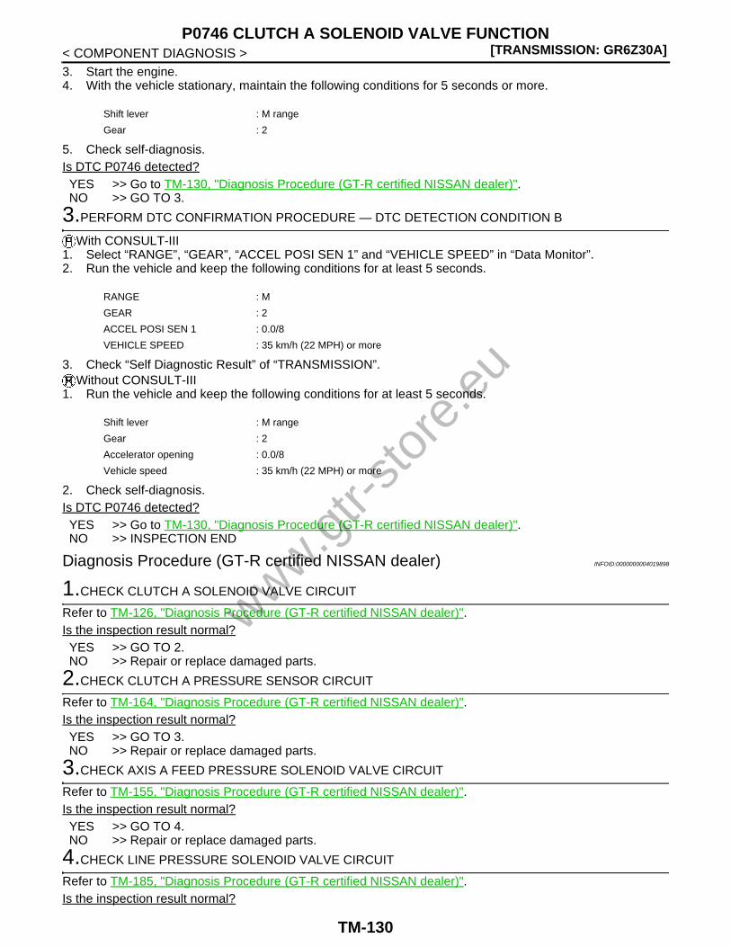
[TRANSMISSION: GR6Z30A]P0746 CLUTCH A SOLENOID VALVE FUNCTION
< COMPONENT DIAGNOSIS >3. Start the engine.4. With the vehicle stationary, maintain the following conditions for 5 seconds or more.
5. Check self-diagnosis.Is DTC P0746 detected?YES >> Go to TM-130, "Diagnosis Procedure (GT-R certified NISSAN dealer)".NO >> GO TO 3.
3.PERFORM DTC CONFIRMATION PROCEDURE — DTC DETECTION CONDITION B
With CONSULT-III1. Select “RANGE”, “GEAR”, “ACCEL POSI SEN 1” and “VEHICLE SPEED” in “Data Monitor”.2. Run the vehicle and keep the following conditions for at least 5 seconds.
3. Check “Self Diagnostic Result” of “TRANSMISSION”.Without CONSULT-III
1. Run the vehicle and keep the following conditions for at least 5 seconds.
2. Check self-diagnosis.Is DTC P0746 detected?YES >> Go to TM-130, "Diagnosis Procedure (GT-R certified NISSAN dealer)".NO >> INSPECTION END
Diagnosis Procedure (GT-R certified NISSAN dealer) INFOID:0000000004019898
1.CHECK CLUTCH A SOLENOID VALVE CIRCUIT
Refer to TM-126, "Diagnosis Procedure (GT-R certified NISSAN dealer)".Is the inspection result normal?YES >> GO TO 2.NO >> Repair or replace damaged parts.
2.CHECK CLUTCH A PRESSURE SENSOR CIRCUIT
Refer to TM-164, "Diagnosis Procedure (GT-R certified NISSAN dealer)".Is the inspection result normal?YES >> GO TO 3.NO >> Repair or replace damaged parts.
3.CHECK AXIS A FEED PRESSURE SOLENOID VALVE CIRCUIT
Refer to TM-155, "Diagnosis Procedure (GT-R certified NISSAN dealer)".Is the inspection result normal?YES >> GO TO 4.NO >> Repair or replace damaged parts.
4.CHECK LINE PRESSURE SOLENOID VALVE CIRCUIT
Refer to TM-185, "Diagnosis Procedure (GT-R certified NISSAN dealer)".Is the inspection result normal?
Shift lever : M range
Gear : 2
RANGE : M
GEAR : 2
ACCEL POSI SEN 1 : 0.0/8
VEHICLE SPEED : 35 km/h (22 MPH) or more
Shift lever : M range
Gear : 2
Accelerator opening : 0.0/8
Vehicle speed : 35 km/h (22 MPH) or more
www.gtr-
store
.eu
TM-130

P0746 CLUTCH A SOLENOID VALVE FUNCTION[TRANSMISSION: GR6Z30A]
C
E
F
G
H
I
J
K
L
M
A
B
M
N
O
P
< COMPONENT DIAGNOSIS >
T
YES >> GO TO 5.NO >> Repair or replace damaged parts.
5.CHECK GROUND CONNECTION
1. Turn ignition switch OFF.2. Check ground connections B31 and ground cable connections. Refer to “Ground Inspection” in XX-XX,
"*****".Is the inspection result normal?YES >> GO TO 6.NO >> Repair or replace damaged parts.
6.CHECK INTERMITTENT INCIDENT
Refer to XX-XX, "*****".Is the inspection result normal?YES >> Replace transmission assembly. Refer to TM-291, "Exploded View (GT-R certified NISSAN
dealer)".NO >> Repair or replace damaged parts.
www.gtr-
store
.eu
TM-131

[TRANSMISSION: GR6Z30A]P0750 SHIFT SOLENOID VALVE 1
< COMPONENT DIAGNOSIS >
P0750 SHIFT SOLENOID VALVE 1
Description (GT-R certified NISSAN dealer) INFOID:0000000004019902
• The shift solenoid valve 1 is installed on the actuator control module and switches the oil passages for the oilpressure that activates the 6th-Neutral shift actuator operating the sleeve A1 and the 2nd-4th shift actuatoroperating the sleeve A2.
• The shift solenoid valve 1 is an ON/OFF type solenoid valve.
DTC Logic (GT-R certified NISSAN dealer) INFOID:0000000004019903
DTC DETECTION LOGIC
DTC CONFIRMATION PROCEDURECAUTION:Be careful of the driving speed.
1.PREPARATION BEFORE OPERATION
If another “DTC CONFIRMATION PROCEDURE” is performed just before the next test, turn the ignitionswitch OFF and wait for 10 seconds or more, then perform the next test.
>> GO TO 2.
2.PERFORM DTC CONFIRMATION PROCEDURE (PART 1)
With CONSULT-III1. Start the engine.2. Shift the shift lever to the A position and run at idle for 5 seconds or more.3. Check “Self Diagnostic Result” of “TRANSMISSION”.
Without CONSULT-III1. Start the engine.2. Shift the shift lever to the A position and run at idle for 5 seconds or more.3. Check self-diagnosis.Is DTC P0750 detected?YES >> Go to TM-132, "Diagnosis Procedure (GT-R certified NISSAN dealer)".NO >> GO TO 3.
3.PERFORM DTC CONFIRMATION PROCEDURE (PART 2)
With CONSULT-III1. Run the vehicle in 3rd gear of M range for 5 seconds or more.2. Check “Self Diagnostic Result” of “TRANSMISSION”.
Without CONSULT-III1. Run the vehicle in 3rd gear of M range for 5 seconds or more.2. Check self-diagnosis.Is DTC P0750 detected?YES >> Go to TM-132, "Diagnosis Procedure (GT-R certified NISSAN dealer)".NO >> INSPECTION END
Diagnosis Procedure (GT-R certified NISSAN dealer) INFOID:0000000004019904
1.CHECK GROUND CONNECTION
1. Turn ignition switch OFF.
DTC Self-diagnosis name DTC detection condition Possible cause
P0750 Shift solenoid valve 1 output
• A DTC is set if the shift solenoid valve 1 monitor value is ON when the shift sole-noid valve 1 command value is OFF.
• A DTC is set if the shift solenoid valve 1 monitor value is OFF when the shift sole-noid valve 1 command value is ON.
• Shift solenoid valve 1• Harness or connector
(Open or short in the shift solenoid valve 1 circuit)
www.gtr-
store
.eu
TM-132
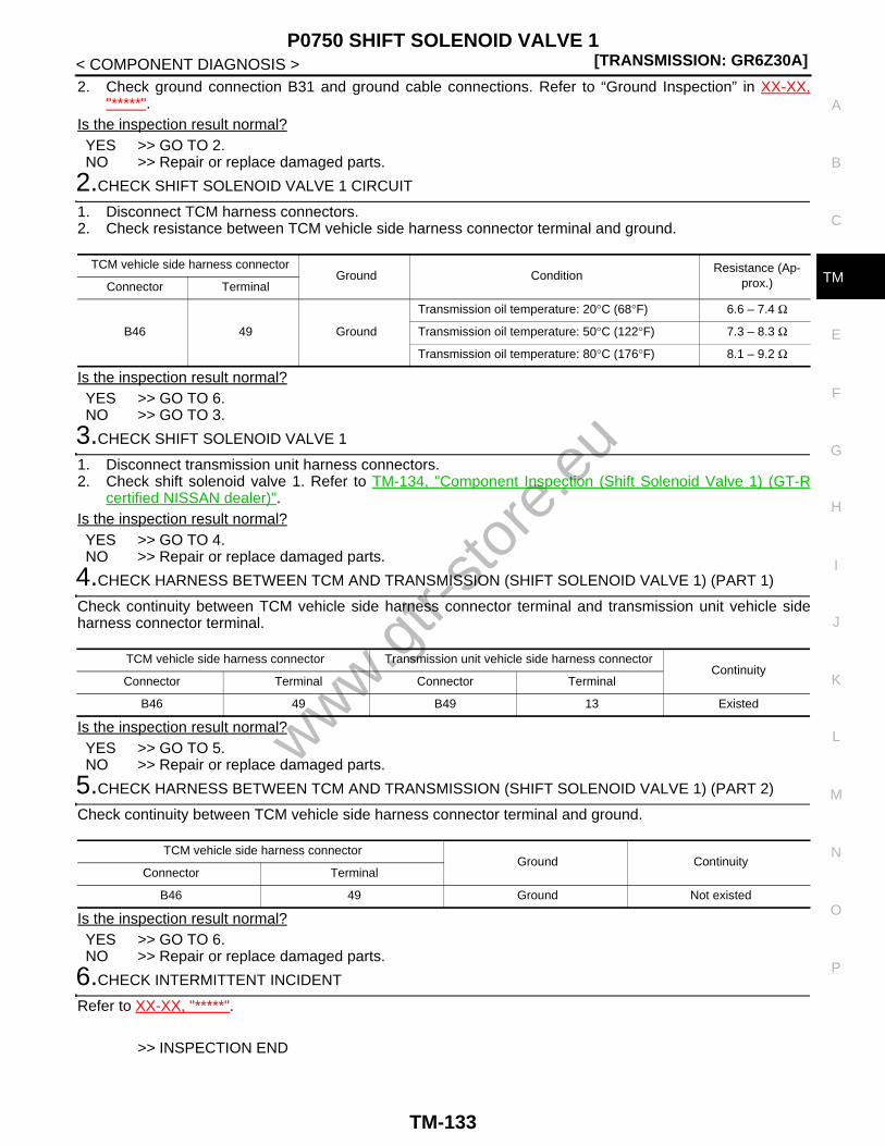
P0750 SHIFT SOLENOID VALVE 1[TRANSMISSION: GR6Z30A]
C
E
F
G
H
I
J
K
L
M
A
B
M
N
O
P
< COMPONENT DIAGNOSIS >
T
2. Check ground connection B31 and ground cable connections. Refer to “Ground Inspection” in XX-XX,"*****".
Is the inspection result normal?YES >> GO TO 2.NO >> Repair or replace damaged parts.
2.CHECK SHIFT SOLENOID VALVE 1 CIRCUIT
1. Disconnect TCM harness connectors.2. Check resistance between TCM vehicle side harness connector terminal and ground.
Is the inspection result normal?YES >> GO TO 6.NO >> GO TO 3.
3.CHECK SHIFT SOLENOID VALVE 1
1. Disconnect transmission unit harness connectors.2. Check shift solenoid valve 1. Refer to TM-134, "Component Inspection (Shift Solenoid Valve 1) (GT-R
certified NISSAN dealer)".Is the inspection result normal?YES >> GO TO 4.NO >> Repair or replace damaged parts.
4.CHECK HARNESS BETWEEN TCM AND TRANSMISSION (SHIFT SOLENOID VALVE 1) (PART 1)
Check continuity between TCM vehicle side harness connector terminal and transmission unit vehicle sideharness connector terminal.
Is the inspection result normal?YES >> GO TO 5.NO >> Repair or replace damaged parts.
5.CHECK HARNESS BETWEEN TCM AND TRANSMISSION (SHIFT SOLENOID VALVE 1) (PART 2)
Check continuity between TCM vehicle side harness connector terminal and ground.
Is the inspection result normal?YES >> GO TO 6.NO >> Repair or replace damaged parts.
6.CHECK INTERMITTENT INCIDENT
Refer to XX-XX, "*****".
>> INSPECTION END
TCM vehicle side harness connectorGround Condition
Resistance (Ap-prox.)Connector Terminal
B46 49 Ground
Transmission oil temperature: 20°C (68°F) 6.6 – 7.4 Ω
Transmission oil temperature: 50°C (122°F) 7.3 – 8.3 Ω
Transmission oil temperature: 80°C (176°F) 8.1 – 9.2 Ω
TCM vehicle side harness connector Transmission unit vehicle side harness connectorContinuity
Connector Terminal Connector Terminal
B46 49 B49 13 Existed
TCM vehicle side harness connectorGround Continuity
Connector Terminal
B46 49 Ground Not existed
www.gtr-
store
.eu
TM-133

[TRANSMISSION: GR6Z30A]P0750 SHIFT SOLENOID VALVE 1
< COMPONENT DIAGNOSIS >
Component Inspection (Shift Solenoid Valve 1) (GT-R certified NISSAN dealer)INFOID:0000000004019905
1.CHECK SHIFT SOLENOID VALVE 1
Check the resistance between transmission unit harness connector terminal and ground.
Is the inspection result normal?YES >> INSPECTION ENDNO >> Repair or replace damaged parts.
Transmission unit harness connectorGround Condition
Resistance (Ap-prox.)Connector Terminal
B49 13 Ground
Transmission oil temperature: 20°C (68°F) 6.6 – 7.4 Ω
Transmission oil temperature: 50°C (122°F) 7.3 – 8.3 Ω
Transmission oil temperature: 80°C (176°F) 8.1 – 9.2 Ω
www.gtr-
store
.eu
TM-134

P0755 SHIFT SOLENOID VALVE 2[TRANSMISSION: GR6Z30A]
C
E
F
G
H
I
J
K
L
M
A
B
M
N
O
P
< COMPONENT DIAGNOSIS >
T
P0755 SHIFT SOLENOID VALVE 2
Description (GT-R certified NISSAN dealer) INFOID:0000000004019906
• The shift solenoid valve 2 is installed on the actuator control module and switches the oil passages for the oilpressure that activates the 6th-Neutral shift actuator operating the sleeve A1 and the 2nd-4th shift actuatoroperating the sleeve A2.
• The shift solenoid valve 2 is a ON/OFF type solenoid valve.
DTC Logic (GT-R certified NISSAN dealer) INFOID:0000000004019907
DTC DETECTION LOGIC
DTC CONFIRMATION PROCEDURECAUTION:Be careful of the driving speed.
1.PREPARATION BEFORE OPERATION
If another “DTC CONFIRMATION PROCEDURE” is performed just before the next test, turn the ignitionswitch OFF and wait for 10 seconds or more, then perform the next test.
>> GO TO 2.
2.PERFORM DTC CONFIRMATION PROCEDURE (PART 1)
With CONSULT-III1. Start the engine.2. Shift the shift lever to the A position and run at idle for 5 seconds or more.3. Check “Self Diagnostic Result” of “TRANSMISSION”.
Without CONSULT-III1. Start the engine.2. Shift the shift lever to the A position and run at idle for 5 seconds or more.3. Check self-diagnosis.Is DTC P0755 detected?YES >> Go to TM-135, "Diagnosis Procedure (GT-R certified NISSAN dealer)".NO >> GO TO 3.
3.PERFORM DTC CONFIRMATION PROCEDURE (PART 2)
With CONSULT-III1. Run the vehicle in 3rd gear of M range for 5 seconds or more.2. Check “Self Diagnostic Result” of “TRANSMISSION”.
Without CONSULT-III1. Run the vehicle in 3rd gear of M range for 5 seconds or more.2. Check self-diagnosis.Is DTC P0755 detected?YES >> Go to TM-135, "Diagnosis Procedure (GT-R certified NISSAN dealer)".NO >> INSPECTION END
Diagnosis Procedure (GT-R certified NISSAN dealer) INFOID:0000000004019908
1.CHECK GROUND CONNECTION
1. Turn ignition switch OFF.
DTC Self-diagnosis name DTC detection condition Possible cause
P0755 Shift solenoid valve 2 output
• A DTC is set if the shift solenoid valve 2 monitor value is ON when the shift sole-noid valve 2 command value is OFF.
• A DTC is set if the shift solenoid valve 2 monitor value is OFF when the shift sole-noid valve 2 command value is ON.
• Shift solenoid valve 2• Harness or connector
(Open or short in the shift solenoid valve 2 circuit)
www.gtr-
store
.eu
TM-135

[TRANSMISSION: GR6Z30A]P0755 SHIFT SOLENOID VALVE 2
< COMPONENT DIAGNOSIS >2. Check ground connection B31 and ground cable connections. Refer to “Ground Inspection” in XX-XX,
"*****".Is the inspection result normal?YES >> GO TO 2.NO >> Repair or replace damaged parts.
2.CHECK SHIFT SOLENOID VALVE 2 CIRCUIT
1. Disconnect TCM harness connectors.2. Check resistance between TCM vehicle side harness connector terminal and ground.
Is the inspection result normal?YES >> GO TO 6.NO >> GO TO 3.
3.CHECK SHIFT SOLENOID VALVE 2
1. Disconnect transmission unit harness connectors.2. Check shift solenoid valve 2. Refer to TM-137, "Component Inspection (Shift Solenoid Valve 2) (GT-R
certified NISSAN dealer)".Is the inspection result normal?YES >> GO TO 4.NO >> Repair or replace damaged parts.
4.CHECK HARNESS BETWEEN TCM AND TRANSMISSION (SHIFT SOLENOID VALVE 2) (PART 1)
Check continuity between TCM vehicle side harness connector terminal and transmission unit vehicle sideharness connector terminal.
Is the inspection result normal?YES >> GO TO 5.NO >> Repair or replace damaged parts.
5.CHECK HARNESS BETWEEN TCM AND TRANSMISSION (SHIFT SOLENOID VALVE 2) (PART 2)
Check continuity between TCM vehicle side harness connector terminal and ground.
Is the inspection result normal?YES >> GO TO 6.NO >> Repair or replace damaged parts.
6.CHECK INTERMITTENT INCIDENT
Refer to XX-XX, "*****".
>> INSPECTION END
TCM vehicle side harness connectorGround Condition
Resistance (Ap-prox.)Connector Terminal
B46 54 Ground
Transmission oil temperature: 20°C (68°F) 6.6 – 7.4 Ω
Transmission oil temperature: 50°C (122°F) 7.3 – 8.3 Ω
Transmission oil temperature: 80°C (176°F) 8.1 – 9.2 Ω
TCM vehicle side harness connector Transmission unit vehicle side harness connectorContinuity
Connector Terminal Connector Terminal
B46 54 B49 20 Existed
TCM vehicle side harness connectorGround Continuity
Connector Terminal
B46 54 Ground Not existed
www.gtr-
store
.eu
TM-136

P0755 SHIFT SOLENOID VALVE 2[TRANSMISSION: GR6Z30A]
C
E
F
G
H
I
J
K
L
M
A
B
M
N
O
P
< COMPONENT DIAGNOSIS >
T
Component Inspection (Shift Solenoid Valve 2) (GT-R certified NISSAN dealer)INFOID:0000000004019909
1.CHECK SHIFT SOLENOID VALVE 2
Check the resistance between transmission unit harness connector terminal and ground.
Is the inspection result normal?YES >> INSPECTION ENDNO >> Repair or replace damaged parts.
Transmission unit harness connectorGround Condition
Resistance (Ap-prox.)Connector Terminal
B49 20 Ground
Transmission oil temperature: 20°C (68°F) 6.6 – 7.4 Ω
Transmission oil temperature: 50°C (122°F) 7.3 – 8.3 Ω
Transmission oil temperature: 80°C (176°F) 8.1 – 9.2 Ω
www.gtr-
store
.eu
TM-137

[TRANSMISSION: GR6Z30A]P0760 SHIFT SOLENOID VALVE 3
< COMPONENT DIAGNOSIS >
P0760 SHIFT SOLENOID VALVE 3
Description (GT-R certified NISSAN dealer) INFOID:0000000004019910
• The shift solenoid valve 3 is installed on the actuator control module and switches the oil passages for the oilpressure that activates the 1st-Reverse shift actuator operating the sleeve B1 and the 3rd-5th shift actuatoroperating the sleeve B2.
• The shift solenoid valve 3 is a ON/OFF type solenoid valve.
DTC Logic (GT-R certified NISSAN dealer) INFOID:0000000004019911
DTC DETECTION LOGIC
DTC CONFIRMATION PROCEDURE
1.PREPARATION BEFORE OPERATION
If another “DTC CONFIRMATION PROCEDURE” is performed just before the next test, turn the ignitionswitch OFF and wait for 10 seconds or more, then perform the next test.
>> GO TO 2.
2.PERFORM DTC CONFIRMATION PROCEDURE (PART 1)
With CONSULT-III1. Start the engine.2. Shift the shift lever to the R position and run at idle for 5 seconds or more.3. Check “Self Diagnostic Result” of “TRANSMISSION”.
Without CONSULT-III1. Start the engine.2. Shift the shift lever to the R position and run at idle for 5 seconds or more.3. Check self-diagnosis.Is DTC P0760 detected?YES >> Go to TM-138, "Diagnosis Procedure (GT-R certified NISSAN dealer)".NO >> GO TO 3.
3.PERFORM DTC CONFIRMATION PROCEDURE (PART 2)
With CONSULT-III1. Shift the shift lever to the A position and run at idle for 5 seconds or more.2. Check “Self Diagnostic Result” of “TRANSMISSION”.
Without CONSULT-III1. Shift the shift lever to the A position and run at idle for 5 seconds or more.2. Check self-diagnosis.Is DTC P0760 detected?YES >> Go to TM-138, "Diagnosis Procedure (GT-R certified NISSAN dealer)".NO >> INSPECTION END
Diagnosis Procedure (GT-R certified NISSAN dealer) INFOID:0000000004019912
1.CHECK GROUND CONNECTION
1. Turn ignition switch OFF.
DTC Self-diagnosis name DTC detection condition Possible cause
P0760 Shift solenoid valve 3 output
• A DTC is set if the shift solenoid valve 3 monitor value is ON when the shift sole-noid valve 3 command value is OFF.
• A DTC is set if the shift solenoid valve 3 monitor value is OFF when the shift sole-noid valve 3 command value is ON.
• Shift solenoid valve 3• Harness or connector
(Open or short in the shift solenoid valve 3 circuit)
www.gtr-
store
.eu
TM-138

P0760 SHIFT SOLENOID VALVE 3[TRANSMISSION: GR6Z30A]
C
E
F
G
H
I
J
K
L
M
A
B
M
N
O
P
< COMPONENT DIAGNOSIS >
T
2. Check ground connection B31 and ground cable connections. Refer to “Ground Inspection” in XX-XX,"*****".
Is the inspection result normal?YES >> GO TO 2.NO >> Repair or replace damaged parts.
2.CHECK SHIFT SOLENOID VALVE 3 CIRCUIT
1. Disconnect TCM harness connectors.2. Check resistance between TCM vehicle side harness connector terminal and ground.
Is the inspection result normal?YES >> GO TO 6.NO >> GO TO 3.
3.CHECK SHIFT SOLENOID VALVE 3
1. Disconnect transmission unit harness connectors.2. Check shift solenoid valve 3. Refer to TM-140, "Component Inspection (Shift Solenoid Valve 3) (GT-R
certified NISSAN dealer)".Is the inspection result normal?YES >> GO TO 4.NO >> Repair or replace damaged parts.
4.CHECK HARNESS BETWEEN TCM AND TRANSMISSION (SHIFT SOLENOID VALVE 3) (PART 1)
Check continuity between TCM vehicle side harness connector terminal and transmission unit vehicle sideharness connector terminal.
Is the inspection result normal?YES >> GO TO 5.NO >> Repair or replace damaged parts.
5.CHECK HARNESS BETWEEN TCM AND TRANSMISSION (SHIFT SOLENOID VALVE 3) (PART 2)
Check continuity between TCM vehicle side harness connector terminal and ground.
Is the inspection result normal?YES >> GO TO 6.NO >> Repair or replace damaged parts.
6.CHECK INTERMITTENT INCIDENT
Refer to XX-XX, "*****".
>> INSPECTION END
TCM vehicle side harness connectorGround Condition
Resistance (Ap-prox.)Connector Terminal
B46 51 Ground
Transmission oil temperature: 20°C (68°F) 6.6 – 7.4 Ω
Transmission oil temperature: 50°C (122°F) 7.3 – 8.3 Ω
Transmission oil temperature: 80°C (176°F) 8.1 – 9.2 Ω
TCM vehicle side harness connector Transmission unit vehicle side harness connectorContinuity
Connector Terminal Connector Terminal
B46 51 B49 27 Existed
TCM vehicle side harness connectorGround Continuity
Connector Terminal
B46 51 Ground Not existed
www.gtr-
store
.eu
TM-139

[TRANSMISSION: GR6Z30A]P0760 SHIFT SOLENOID VALVE 3
< COMPONENT DIAGNOSIS >
Component Inspection (Shift Solenoid Valve 3) (GT-R certified NISSAN dealer)INFOID:0000000004019913
1.CHECK SHIFT SOLENOID VALVE 3
Check the resistance between transmission unit harness connector terminal and ground.
Is the inspection result normal?YES >> INSPECTION ENDNO >> Repair or replace damaged parts.
Transmission unit harness connectorGround Condition
Resistance (Ap-prox.)Connector Terminal
B49 27 Ground
Transmission oil temperature: 20°C (68°F) 6.6 – 7.4 Ω
Transmission oil temperature: 50°C (122°F) 7.3 – 8.3 Ω
Transmission oil temperature: 80°C (176°F) 8.1 – 9.2 Ω
www.gtr-
store
.eu
TM-140

P0765 SHIFT SOLENOID VALVE 4[TRANSMISSION: GR6Z30A]
C
E
F
G
H
I
J
K
L
M
A
B
M
N
O
P
< COMPONENT DIAGNOSIS >
T
P0765 SHIFT SOLENOID VALVE 4
Description (GT-R certified NISSAN dealer) INFOID:0000000004019914
• The shift solenoid valve 4 is installed on the actuator control module and switches the oil passages for the oilpressure that activates the 1st-Reverse shift actuator operating the sleeve B1 and the 3rd-5th shift actuatoroperating the sleeve B2.
• The shift solenoid valve 4 is a ON/OFF type solenoid valve.
DTC Logic (GT-R certified NISSAN dealer) INFOID:0000000004019915
DTC DETECTION LOGIC
DTC CONFIRMATION PROCEDURE
1.PREPARATION BEFORE OPERATION
If another “DTC CONFIRMATION PROCEDURE” is performed just before the next test, turn the ignitionswitch OFF and wait for 10 seconds or more, then perform the next test.
>> GO TO 2.
2.PERFORM DTC CONFIRMATION PROCEDURE (PART 1)
With CONSULT-III1. Start the engine.2. Shift the shift lever to the R position and run at idle for 5 seconds or more.3. Check “Self Diagnostic Result” of “TRANSMISSION”.
Without CONSULT-III1. Start the engine.2. Shift the shift lever to the R position and run at idle for 5 seconds or more.3. Check self-diagnosis.Is DTC P0765 detected?YES >> Go to TM-141, "Diagnosis Procedure (GT-R certified NISSAN dealer)".NO >> GO TO 3.
3.PERFORM DTC CONFIRMATION PROCEDURE (PART 2)
With CONSULT-III1. Shift the shift lever to the A position and run at idle for 5 seconds or more.2. Check “Self Diagnostic Result” of “TRANSMISSION”.
Without CONSULT-III1. Shift the shift lever to the A position and run at idle for 5 seconds or more.2. Check self-diagnosis.Is DTC P0765 detected?YES >> Go to TM-141, "Diagnosis Procedure (GT-R certified NISSAN dealer)".NO >> INSPECTION END
Diagnosis Procedure (GT-R certified NISSAN dealer) INFOID:0000000004019916
1.CHECK GROUND CONNECTION
1. Turn ignition switch OFF.2. Check ground connection B31 and ground cable connections. Refer to “Ground Inspection” in XX-XX,
"*****".
DTC Self-diagnosis name DTC detection condition Possible cause
P0765 Shift solenoid valve 4 output
• A DTC is set if the shift solenoid valve 4 monitor value is ON when the shift sole-noid valve 4 command value is OFF.
• A DTC is set if the shift solenoid valve 4 monitor value is OFF when the shift sole-noid valve 4 command value is ON.
• Shift solenoid valve 4• Harness or connector
(Open or short in the shift solenoid valve 4 circuit)
www.gtr-
store
.eu
TM-141

[TRANSMISSION: GR6Z30A]P0765 SHIFT SOLENOID VALVE 4
< COMPONENT DIAGNOSIS >Is the inspection result normal?YES >> GO TO 2.NO >> Repair or replace damaged parts.
2.CHECK SHIFT SOLENOID VALVE 4 CIRCUIT
1. Disconnect TCM harness connectors.2. Check resistance between TCM vehicle side harness connector terminal and ground.
Is the inspection result normal?YES >> GO TO 6.NO >> GO TO 3.
3.CHECK SHIFT SOLENOID VALVE 4
1. Disconnect transmission unit harness connectors.2. Check shift solenoid valve 4. Refer to TM-142, "Component Inspection (GT-R certified NISSAN dealer)".Is the inspection result normal?YES >> GO TO 4.NO >> Repair or replace damaged parts.
4.CHECK HARNESS BETWEEN TCM AND TRANSMISSION (SHIFT SOLENOID VALVE 4) (PART 1)
Check continuity between TCM vehicle side harness connector terminal and transmission unit vehicle sideharness connector terminal.
Is the inspection result normal?YES >> GO TO 5.NO >> Repair or replace damaged parts.
5.CHECK HARNESS BETWEEN TCM AND TRANSMISSION (SHIFT SOLENOID VALVE 4) (PART 2)
Check continuity between TCM vehicle side harness connector terminal and ground.
Is the inspection result normal?YES >> GO TO 6.NO >> Repair or replace damaged parts.
6.CHECK INTERMITTENT INCIDENT
Refer to XX-XX, "*****".
>> INSPECTION END
Component Inspection (GT-R certified NISSAN dealer) INFOID:0000000004019917
1.CHECK SHIFT SOLENOID VALVE 4
Check the resistance between transmission unit harness connector terminal and ground.
TCM vehicle side harness connectorGround Condition
Resistance (Ap-prox.)Connector Terminal
B46 56 Ground
Transmission oil temperature: 20°C (68°F) 6.6 – 7.4 Ω
Transmission oil temperature: 50°C (122°F) 7.3 – 8.3 Ω
Transmission oil temperature: 80°C (176°F) 8.1 – 9.2 Ω
TCM vehicle side harness connector Transmission unit vehicle side harness connectorContinuity
Connector Terminal Connector Terminal
B46 56 B49 7 Existed
TCM vehicle side harness connectorGround Continuity
Connector Terminal
B46 56 Ground Not existed
www.gtr-
store
.eu
TM-142

P0765 SHIFT SOLENOID VALVE 4[TRANSMISSION: GR6Z30A]
C
E
F
G
H
I
J
K
L
M
A
B
M
N
O
P
< COMPONENT DIAGNOSIS >
T
Is the inspection result normal?YES >> INSPECTION ENDNO >> Repair or replace damaged parts.
Transmission unit harness connectorGround Condition
Resistance (Ap-prox.)Connector Terminal
B49 7 Ground
Transmission oil temperature: 20°C (68°F) 6.6 – 7.4 Ω
Transmission oil temperature: 50°C (122°F) 7.3 – 8.3 Ω
Transmission oil temperature: 80°C (176°F) 8.1 – 9.2 Ω
www.gtr-
store
.eu
TM-143

[TRANSMISSION: GR6Z30A]P0770 SEQUENCE SOLENOID VALVE
< COMPONENT DIAGNOSIS >
P0770 SEQUENCE SOLENOID VALVE
Description (GT-R certified NISSAN dealer) INFOID:0000000004019918
• The sequence solenoid valve is installed on the actuator control module and switches the oil passages foroperating the low speed gear sleeve (sleeve A2 and sleeve B1) and for operating the high speed gearsleeve (sleeve A1 and sleeve B2).
• The sequence solenoid valve is a ON/OFF type solenoid valve.
DTC Logic (GT-R certified NISSAN dealer) INFOID:0000000004019919
DTC DETECTION LOGIC
DTC CONFIRMATION PROCEDURECAUTION:Be careful of the driving speed.
1.PREPARATION BEFORE OPERATION
If another “DTC CONFIRMATION PROCEDURE” is performed just before the next test, turn the ignitionswitch OFF and wait for 10 seconds or more, then perform the next test.
>> GO TO 2.
2.PERFORM DTC CONFIRMATION PROCEDURE (PART 1)
With CONSULT-III1. Start the engine.2. Shift the shift lever to the A position and run at idle for 5 seconds or more.3. Check “Self Diagnostic Result” of “TRANSMISSION”.
Without CONSULT-III1. Start the engine.2. Shift the shift lever to the A position and run at idle for 5 seconds or more.3. Check self-diagnosis.Is DTC P0770 detected?YES >> Go to TM-145, "Diagnosis Procedure (GT-R certified NISSAN dealer)".NO >> GO TO 3.
3.PERFORM DTC CONFIRMATION PROCEDURE (PART 2)
With CONSULT-III1. Run the vehicle in 2nd gear of M range for 5 seconds or more.2. Check “Self Diagnostic Result” of “TRANSMISSION”.
Without CONSULT-III1. Run the vehicle in 2nd gear of M range for 5 seconds or more.2. Check self-diagnosis.Is DTC P0770 detected?YES >> Go to TM-145, "Diagnosis Procedure (GT-R certified NISSAN dealer)".NO >> INSPECTION END
DTC Self-diagnosis name DTC detection condition Possible cause
P0770Sequence solenoid valve output
• A DTC is set if the sequence solenoid valve monitor value is ON when the se-quence solenoid valve command value is OFF.
• A DTC is set if the sequence solenoid valve monitor value is OFF when the se-quence solenoid valve command value is ON.
• Sequence solenoid valve• Harness or connector
(Open or short in the sequence solenoid valve circuit)
www.gtr-
store
.eu
TM-144

P0770 SEQUENCE SOLENOID VALVE[TRANSMISSION: GR6Z30A]
C
E
F
G
H
I
J
K
L
M
A
B
M
N
O
P
< COMPONENT DIAGNOSIS >
T
Diagnosis Procedure (GT-R certified NISSAN dealer) INFOID:0000000004019920
1.CHECK GROUND CONNECTION
1. Turn ignition switch OFF.2. Check ground connection B31 and ground cable connections. Refer to “Ground Inspection” in XX-XX,
"*****".Is the inspection result normal?YES >> GO TO 2.NO >> Repair or replace damaged parts.
2.CHECK SEQUENCE SOLENOID VALVE CIRCUIT
1. Disconnect TCM harness connectors.2. Check resistance between TCM vehicle side harness connector terminal and ground.
Is the inspection result normal?YES >> GO TO 6.NO >> GO TO 3.
3.CHECK SEQUENCE SOLENOID VALVE
1. Disconnect transmission unit harness connectors.2. Check sequence solenoid valve. Refer to TM-146, "Component Inspection (Sequence Solenoid Valve)
(GT-R certified NISSAN dealer)".Is the inspection result normal?YES >> GO TO 4.NO >> Repair or replace damaged parts.
4.CHECK HARNESS BETWEEN TCM AND TRANSMISSION (SEQUENCE SOLENOID VALVE) (PART 1)
Check continuity between TCM vehicle side harness connector terminal and transmission unit vehicle sideharness connector terminal.
Is the inspection result normal?YES >> GO TO 5.NO >> Repair or replace damaged parts.
5.CHECK HARNESS BETWEEN TCM AND TRANSMISSION (SEQUENCE SOLENOID VALVE) (PART 2)
Check continuity between TCM vehicle side harness connector terminal and ground.
Is the inspection result normal?YES >> GO TO 6.NO >> Repair or replace damaged parts.
6.CHECK INTERMITTENT INCIDENT
Refer to XX-XX, "*****".
TCM vehicle side harness connectorGround Condition
Resistance (Ap-prox.)Connector Terminal
B46 53 Ground
Transmission oil temperature: 20°C (68°F) 6.6 – 7.4 Ω
Transmission oil temperature: 50°C (122°F) 7.3 – 8.3 Ω
Transmission oil temperature: 80°C (176°F) 8.1 – 9.2 Ω
TCM vehicle side harness connector Transmission unit vehicle side harness connectorContinuity
Connector Terminal Connector Terminal
B46 53 B49 6 Existed
TCM vehicle side harness connectorGround Continuity
Connector Terminal
B46 53 Ground Not existed
www.gtr-
store
.eu
TM-145
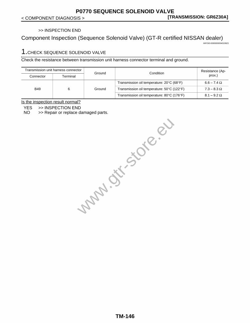
[TRANSMISSION: GR6Z30A]P0770 SEQUENCE SOLENOID VALVE
< COMPONENT DIAGNOSIS >
>> INSPECTION END
Component Inspection (Sequence Solenoid Valve) (GT-R certified NISSAN dealer)INFOID:0000000004019921
1.CHECK SEQUENCE SOLENOID VALVE
Check the resistance between transmission unit harness connector terminal and ground.
Is the inspection result normal?YES >> INSPECTION ENDNO >> Repair or replace damaged parts.
Transmission unit harness connectorGround Condition
Resistance (Ap-prox.)Connector Terminal
B49 6 Ground
Transmission oil temperature: 20°C (68°F) 6.6 – 7.4 Ω
Transmission oil temperature: 50°C (122°F) 7.3 – 8.3 Ω
Transmission oil temperature: 80°C (176°F) 8.1 – 9.2 Ω
www.gtr-
store
.eu
TM-146

P0775 CLUTCH B SOLENOID VALVE[TRANSMISSION: GR6Z30A]
C
E
F
G
H
I
J
K
L
M
A
B
M
N
O
P
< COMPONENT DIAGNOSIS >
T
P0775 CLUTCH B SOLENOID VALVE
Description (GT-R certified NISSAN dealer) INFOID:0000000004019922
• The clutch B solenoid valve is installed on the front control module and controls the clutch B (a clutch for oddnumber gears and reverse) with the current signal from TCM.
• The clutch B solenoid valve is an N/L type (normal low) in which no control oil pressure is built up when nocurrent flows through the coil.
DTC Logic (GT-R certified NISSAN dealer) INFOID:0000000004019923
DTC DETECTION LOGICNOTE:If DTC P0700 is detected, first diagnose the DTC P0700 first. Refer to TM-58, "DTC Logic (GT-R certified NIS-SAN dealer)".
DTC CONFIRMATION PROCEDURE
1.PREPARATION BEFORE OPERATION
If another “DTC CONFIRMATION PROCEDURE” is performed just before the next test, turn the ignitionswitch OFF and wait for 10 seconds or more, then perform the next test.
>> GO TO 2.
2.PERFORM DTC CONFIRMATION PROCEDURE
With CONSULT-III1. Turn the ignition switch ON.2. Shift the shift lever to the N position.3. Start the engine.4. Select “RANGE” and “GEAR” in “Data Monitor”.5. With the vehicle stationary, maintain the following conditions for 5 seconds or more.
6. Check “Self Diagnostic Result” of “TRANSMISSION”.Without CONSULT-III
1. Turn the ignition switch ON.2. Shift the shift lever to the N position.3. Start the engine.4. With the vehicle stationary, maintain the following conditions for 5 seconds or more.
5. Check self-diagnosis.Is DTC P0775 detected?YES >> Go to TM-147, "Diagnosis Procedure (GT-R certified NISSAN dealer)".NO >> INSPECTION END
Diagnosis Procedure (GT-R certified NISSAN dealer) INFOID:0000000004019924
1.CHECK GROUND CONNECTION
1. Turn ignition switch OFF.
DTC Self-diagnosis name DTC detection condition Possible cause
P0775Clutch B solenoid valve cur-rent
A DTC is set if the clutch B solenoid valve current value is less than 0.05 A when the clutch B solenoid valve target current value is more than 0.2 A.
• Clutch B solenoid valve• Harness or connector
(Open or short in the clutch B solenoid valve circuit)
RANGE : M
GEAR : 1
Shift lever : M range
Gear : 1
www.gtr-
store
.eu
TM-147

[TRANSMISSION: GR6Z30A]P0775 CLUTCH B SOLENOID VALVE
< COMPONENT DIAGNOSIS >2. Check ground connections B31 and ground cable connections. Refer to “Ground Inspection” in XX-XX,
"*****".Is the inspection result normal?YES >> GO TO 2.NO >> Repair or replace damaged parts.
2.CHECK CLUTCH B SOLENOID VALVE CIRCUIT (PART 1)
1. Disconnect TCM harness connectors.2. Check resistance between TCM vehicle side harness connector terminals.
Is the inspection result normal?YES >> GO TO 3.NO >> GO TO 4.
3.CHECK CLUTCH B SOLENOID VALVE CIRCUIT (PART 2)
Check continuity between TCM vehicle side harness connector terminals and ground.
Is the inspection result normal?YES >> GO TO 7.NO >> GO TO 4.
4.CHECK CLUTCH B SOLENOID VALVE
1. Disconnect transmission unit harness connectors.2. Check clutch B solenoid valve. Refer to TM-149, "Component Inspection (Clutch B Solenoid Valve) (GT-R
certified NISSAN dealer)".Is the inspection result normal?YES >> GO TO 5.NO >> Repair or replace damaged parts.
5.CHECK HARNESS BETWEEN TCM AND TRANSMISSION (CLUTCH B SOLENOID VALVE) (PART 1)
Check continuity between TCM vehicle side harness connector terminals and transmission unit vehicle sideharness connector terminals.
Is the inspection result normal?YES >> GO TO 6.NO >> Repair or replace damaged parts.
6.CHECK HARNESS BETWEEN TCM AND TRANSMISSION (CLUTCH B SOLENOID VALVE) (PART 2)
Check continuity between TCM vehicle side harness connector terminals and ground.
TCM vehicle side harness connectorCondition
Resistance (Ap-prox.)Connector Terminal
B47 123 128
Transmission oil temperature: 20°C (68°F) 4.6 – 5.0 Ω
Transmission oil temperature: 50°C (122°F) 5.1 – 5.6 Ω
Transmission oil temperature: 80°C (176°F) 5.6 – 6.2 Ω
TCM vehicle side harness connectorGround Continuity
Connector Terminal
B47123
Ground Not existed128
TCM vehicle side harness connector Transmission unit vehicle side harness connectorContinuity
Connector Terminal Connector Terminal
B47123
B5042
Existed128 43
www.gtr-
store
.eu
TM-148

P0775 CLUTCH B SOLENOID VALVE[TRANSMISSION: GR6Z30A]
C
E
F
G
H
I
J
K
L
M
A
B
M
N
O
P
< COMPONENT DIAGNOSIS >
T
Is the inspection result normal?YES >> GO TO 7.NO >> Repair or replace damaged parts.
7.CHECK INTERMITTENT INCIDENT
Refer to XX-XX, "*****".
>> INSPECTION END
Component Inspection (Clutch B Solenoid Valve) (GT-R certified NISSAN dealer)INFOID:0000000004019925
1.CHECK CLUTCH B SOLENOID VALVE (PART 1)
Check the resistance between transmission unit harness connector terminals.
Is the inspection result normal?YES >> GO TO 2.NO >> Repair or replace damaged parts.
2.CHECK CLUTCH B SOLENOID VALVE (PART 2)
Check continuity between transmission unit harness connector terminal and ground.
Is the inspection result normal?YES >> INSPECTION ENDNO >> Repair or replace damaged parts.
TCM vehicle side harness connectorGround Continuity
Connector Terminal
B47123
Ground Not existed128
Transmission unit harness connectorCondition
Resistance (Ap-prox.)Connector Terminal
B50 42 43
Transmission oil temperature: 20°C (68°F) 4.6 – 5.0 Ω
Transmission oil temperature: 50°C (122°F) 5.1 – 5.6 Ω
Transmission oil temperature: 80°C (176°F) 5.6 – 6.2 Ω
Transmission unit harness connectorGround Continuity
Connector Terminal
B5042
Ground Not existed43www.g
tr-sto
re.e
u
TM-149

[TRANSMISSION: GR6Z30A]P0776 CLUTCH B SOLENOID VALVE FUNCTION
< COMPONENT DIAGNOSIS >
P0776 CLUTCH B SOLENOID VALVE FUNCTION
Description (GT-R certified NISSAN dealer) INFOID:0000000004019926
The current signal from TCM controls the oil pressure to be applied to the clutch B (a clutch for odd numbergears and reverse) engaging or releasing of the clutch B.
DTC Logic (GT-R certified NISSAN dealer) INFOID:0000000004019927
DTC DETECTION LOGICNOTE:If DTC P0845 is detected, first diagnose the DTC P0845. Refer to TM-166, "DTC Logic (GT-R certified NIS-SAN dealer)".
DTC CONFIRMATION PROCEDURE
1.PREPARATION BEFORE OPERATION
If another “DTC CONFIRMATION PROCEDURE” is performed just before the next test, turn the ignitionswitch OFF and wait for 10 seconds or more, then perform the next test.
>> GO TO 2.
2.PERFORM DTC CONFIRMATION PROCEDURE — DTC DETECTION CONDITION A
With CONSULT-III1. Turn the ignition switch ON.2. Shift the shift lever to N the position.3. Start the engine.4. Select “RANGE” and “GEAR” in “Data Monitor”.5. With the vehicle stationary, maintain the following conditions for 5 seconds or more.
6. Check “Self Diagnostic Result” of “TRANSMISSION”.Without CONSULT-III
1. Turn the ignition switch ON.2. Shift the shift lever to N the position.
DTC Self-diagnosis item DTC detection condition Possible cause
P0776
Monitor clutch B solenoid valve oil pressure difference
A
A DTC is set if the clutch B pressure sensor value is higher than the clutch B pressure target value by 0.2 MPa (2.04
kg/cm2, 29 psi) or more.
• Clutch B solenoid valve• Clutch B pressure sensor• Clutch B oil passage• Harness or connector
(Open or short in the clutch B solenoid valve circuit)(Open or short in the clutch B pressure sensor circuit)
Clutch B solenoid valve oil pressure output low
B
A DTC is set if the difference between the engine speed (CAN signal) and clutch B speed sensor value is 1,000 rpm or more with clutch B.
• Clutch B solenoid valve• Clutch B pressure sensor• Axis B feed pressure solenoid valve• Line pressure solenoid valve• Oil passage between line pressure and
clutch B pressure• Harness or connector
(Open or short in the clutch B solenoid valve circuit)(Open or short in the clutch B pressure sensor circuit)(Open or short in the axis B feed pressure solenoid valve circuit)(Open or short in the line pressure sole-noid valve circuit)
RANGE : M
GEAR : 1
www.gtr-
store
.eu
TM-150

P0776 CLUTCH B SOLENOID VALVE FUNCTION[TRANSMISSION: GR6Z30A]
C
E
F
G
H
I
J
K
L
M
A
B
M
N
O
P
< COMPONENT DIAGNOSIS >
T
3. Start the engine.4. With the vehicle stationary, maintain the following conditions for 5 seconds or more.
5. Check self-diagnosis.Is DTC P0776 detected?YES >> Go to TM-151, "Diagnosis Procedure (GT-R certified NISSAN dealer)".NO >> GO TO 3.
3.PERFORM DTC CONFIRMATION PROCEDURE — DTC DETECTION CONDITION B
With CONSULT-III1. Select “RANGE”, “GEAR”, “ACCEL POSI SEN 1” and “VEHICLE SPEED” in “Data Monitor”.2. Run the vehicle and keep the following conditions for at least 5 seconds.
3. Check “Self Diagnostic Result” of “TRANSMISSION”.Without CONSULT-III
1. Run the vehicle and keep the following conditions for at least 5 seconds.
2. Check self-diagnosis.Is DTC P0776 detected?YES >> Go to TM-151, "Diagnosis Procedure (GT-R certified NISSAN dealer)".NO >> INSPECTION END
Diagnosis Procedure (GT-R certified NISSAN dealer) INFOID:0000000004019928
1.CHECK CLUTCH B SOLENOID VALVE CIRCUIT
Refer to TM-147, "Diagnosis Procedure (GT-R certified NISSAN dealer)".Is the inspection result normal?YES >> GO TO 2.NO >> Repair or replace damaged parts.
2.CHECK CLUTCH B PRESSURE SENSOR CIRCUIT
Refer to TM-167, "Diagnosis Procedure (GT-R certified NISSAN dealer)".Is the inspection result normal?YES >> GO TO 3.NO >> Repair or replace damaged parts.
3.CHECK AXIS B FEED PRESSURE SOLENOID VALVE CIRCUIT
Refer to TM-176, "Diagnosis Procedure (GT-R certified NISSAN dealer)".Is the inspection result normal?YES >> GO TO 4.NO >> Repair or replace damaged parts.
4.CHECK LINE PRESSURE SOLENOID VALVE CIRCUIT
Refer to TM-185, "Diagnosis Procedure (GT-R certified NISSAN dealer)".Is the inspection result normal?
Shift lever : M range
Gear : 1
RANGE : M
GEAR : 1
ACCEL POSI SEN 1 : 0.0/8
VEHICLE SPEED : 20 km/h (13 MPH) or more
Shift lever : M range
Gear : 1
Accelerator opening : 0.0/8
Vehicle speed : 20 km/h (13 MPH) or more
www.gtr-
store
.eu
TM-151

[TRANSMISSION: GR6Z30A]P0776 CLUTCH B SOLENOID VALVE FUNCTION
< COMPONENT DIAGNOSIS >YES >> GO TO 5.NO >> Repair or replace damaged parts.
5.CHECK GROUND CONNECTION
1. Turn ignition switch OFF.2. Check ground connections B31 and ground cable connections. Refer to “Ground Inspection” in XX-XX,
"*****".Is the inspection result normal?YES >> GO TO 6.NO >> Repair or replace damaged parts.
6.CHECK INTERMITTENT INCIDENT
Refer to XX-XX, "*****".Is the inspection result normal?YES >> Replace transmission assembly. Refer to TM-291, "Exploded View (GT-R certified NISSAN
dealer)".NO >> Repair or replace damaged parts.
www.gtr-
store
.eu
TM-152

P0790 SET-UP SWITCH (TRANSMISSION)[TRANSMISSION: GR6Z30A]
C
E
F
G
H
I
J
K
L
M
A
B
M
N
O
P
< COMPONENT DIAGNOSIS >
T
P0790 SET-UP SWITCH (TRANSMISSION)
Description (GT-R certified NISSAN dealer) INFOID:0000000004019932
The set-up switch (transmission) is installed on the cluster lid C and commands the driving mode transition toTCM according to a driver's request.
DTC Logic (GT-R certified NISSAN dealer) INFOID:0000000004019933
DTC DETECTION LOGIC
DTC CONFIRMATION PROCEDURE
1.CHECK BEFORE OPERATION
If another “DTC CONFIRMATION PROCEDURE” is performed just before the next test, turn the ignitionswitch OFF and wait for 10 seconds or more, then perform the next test.
>> GO TO 2.
2.PERFORM DTC CONFIRMATION PROCEDURE
With CONSULT-III1. Start the engine and wait for 1 minute or more.2. Check “Self Diagnostic Result” of “TRANSMISSION”.Is DTC P0790 detected?YES >> Go to TM-88, "Diagnosis Procedure (GT-R certified NISSAN dealer)".NO >> INSPECTION END
Diagnosis Procedure (GT-R certified NISSAN dealer) INFOID:0000000004019934
1.CHECK GROUND CONNECTION
1. Turn ignition switch OFF.2. Check ground connections B31 and M95. Refer to “Ground Inspection” in XX-XX, "*****".Is the inspection result normal?YES >> GO TO 2.NO >> Repair or replace damaged parts.
2.CHECK SET-UP SWITCH (TRANSMISSION)
1. Disconnect set-up switch (transmission) harness connector.2. Check set-up switch (transmission). Refer to TM-191, "Component Inspection [Paddle Shifter (Shift-up
Switch)] (GT-R certified NISSAN dealer)".Is the inspection result normal?YES >> GO TO 3.NO >> Repair or replace damaged parts.
3.CHECK HARNESS BETWEEN TCM AND SET-UP SWITCH (TRANSMISSION)
1. Disconnect TCM harness connectors.2. Check continuity between TCM vehicle side harness connector terminal and ground.
DTC Self-diagnosis name DTC detection condition Possible cause
P0790Continuation of set-up switch (transmission) ON
A DTC is set if TCM detects the set-up switch (transmission) ON signal for a certain period of time.
• Set-up switch (transmission)• Harness or connector
[Short in the set-up switch (transmission) circuit]
www.gtr-
store
.eu
TM-153

[TRANSMISSION: GR6Z30A]P0790 SET-UP SWITCH (TRANSMISSION)
< COMPONENT DIAGNOSIS >
Is the inspection result normal?YES >> GO TO 4.NO >> Repair or replace damaged parts.
4.CHECK HARNESS BETWEEN SET-UP SWITCH (TRANSMISSION) AND GROUND
Check continuity between set-up switch (transmission) vehicle side harness connector terminal and ground.
Is the inspection result normal?YES >> GO TO 5.NO >> Repair or replace damaged parts.
5.CHECK INTERMITTENT INCIDENT
Refer to XX-XX, "*****".
>> INSPECTION END
Component Inspection [Set-up Switch (Transmission)] (GT-R certified NISSAN dealer)INFOID:0000000004019935
1.CHECK SET-UP SWITCH (TRANSMISSION)
Check continuity between set-up switch (transmission) connector terminals.
Is the inspection result normal?YES >> INSPECTION ENDNO >> Replace set-up switch.
TCM vehicle side harness connectorGround Continuity
Connector Terminal
B4534
Ground Not existed37
Set-up switch (transmission) vehicle side harness connectorGround Continuity
Connector Terminal
M73 17 Ground Existed
Set-up switch (transmission) connectorCondition Continuity
Connector Terminal
M73
11
17
With the knob of the set-up switch (transmission) pressed onto the R side
Existed
Other than the above Not existed
23
With the knob of the set-up switch (transmission) pressed onto the SNOW side
Existed
Other than the above Not existed
www.gtr-
store
.eu
TM-154

P0795 AXIS A FEED PRESSURE SOLENOID VALVE[TRANSMISSION: GR6Z30A]
C
E
F
G
H
I
J
K
L
M
A
B
M
N
O
P
< COMPONENT DIAGNOSIS >
T
P0795 AXIS A FEED PRESSURE SOLENOID VALVE
Description (GT-R certified NISSAN dealer) INFOID:0000000004019936
• The axis A feed pressure solenoid valve is installed on the actuator control module and builds up the sourcepressure for the gear operation actuators for even number gears and for the clutch A pressure solenoidvalve based on the signals from TCM. The solenoid valves adjust the source pressure to drive the gears andclutches.
• The axis A feed pressure solenoid valve is an N/L type (normal low) in which no control oil pressure is builtup when no current flows through the coil.
DTC Logic (GT-R certified NISSAN dealer) INFOID:0000000004019937
DTC DETECTION LOGICNOTE:If DTC P0700 is detected, first diagnose the DTC P0700. Refer to TM-58, "DTC Logic (GT-R certified NISSANdealer)".
DTC CONFIRMATION PROCEDURE
1.PREPARATION BEFORE OPERATION
If another “DTC CONFIRMATION PROCEDURE” is performed just before the next test, turn the ignitionswitch OFF and wait for 10 seconds or more, then perform the next test.
>> GO TO 2.
2.PERFORM DTC CONFIRMATION PROCEDURE
With CONSULT-III1. Turn the ignition switch ON.2. Shift the shift lever to the N position.
CAUTION:No shift position indicator in the combination meter blinks.
3. Start the engine.4. Move the shift lever to the N position and run at idle for 5 seconds or more.5. Check “Self Diagnostic Result” of “TRANSMISSION”.
Without CONSULT-III1. Turn the ignition switch ON.2. Shift the shift lever to the N position.
CAUTION:No shift position indicator in the combination meter blinks.
3. Start the engine.4. Move the shift lever to the N position and run at idle for 5 seconds or more.5. Check self-diagnosis.Is DTC P0795 detected?YES >> Go to TM-155, "Diagnosis Procedure (GT-R certified NISSAN dealer)".NO >> INSPECTION END
Diagnosis Procedure (GT-R certified NISSAN dealer) INFOID:0000000004019938
1.CHECK GROUND CONNECTION
1. Turn ignition switch OFF.
DTC Self-diagnosis name DTC detection condition Possible cause
P0795Axis A feed pressure sole-noid valve current
A DTC is set if the axis A feed pressure sole-noid valve monitor current value is less than 0.2 A when the axis A feed pressure solenoid valve target current value is more than 0.38 A.
• Axis A feed pressure solenoid valve• Harness or connector
(Open or short in the axis A feed pressure solenoid valve circuit)
www.gtr-
store
.eu
TM-155

[TRANSMISSION: GR6Z30A]P0795 AXIS A FEED PRESSURE SOLENOID VALVE
< COMPONENT DIAGNOSIS >2. Check ground connections B31 and ground cable connections. Refer to “Ground Inspection” in XX-XX,
"*****".Is the inspection result normal?YES >> GO TO 2.NO >> Repair or replace damaged parts.
2.CHECK AXIS A FEED PRESSURE SOLENOID VALVE CIRCUIT (PART 1)
1. Disconnect TCM harness connectors.2. Check resistance between TCM vehicle side harness connector terminals.
Is the inspection result normal?YES >> GO TO 3.NO >> GO TO 4.
3.CHECK AXIS A FEED PRESSURE SOLENOID VALVE CIRCUIT (PART 2)
Check continuity between TCM vehicle side harness connector terminals and ground.
Is the inspection result normal?YES >> GO TO 7.NO >> GO TO 4.
4.CHECK AXIS A FEED PRESSURE SOLENOID VALVE
1. Disconnect transmission unit harness connectors.2. Check axis A feed pressure solenoid valve. Refer to TM-157, "Component Inspection (Axis A Feed Pres-
sure Solenoid Valve) (GT-R certified NISSAN dealer)".Is the inspection result normal?YES >> GO TO 5.NO >> Repair or replace damaged parts.
5.CHECK HARNESS BETWEEN TCM AND TRANSMISSION (AXIS A FEED PRESSURE SOLENOIDVALVE) (PART 1)
Check continuity between TCM vehicle side harness connector terminals and transmission unit vehicle sideharness connector terminals.
Is the inspection result normal?YES >> GO TO 6.NO >> Repair or replace damaged parts.
6.CHECK HARNESS BETWEEN TCM AND TRANSMISSION (AXIS A FEED PRESSURE SOLENOIDVALVE) (PART 2)
Check continuity between TCM vehicle side harness connector terminals and ground.
TCM vehicle side harness connectorCondition
Resistance (Ap-prox.)Connector Terminal
B46 57 62
Transmission oil temperature: 20°C (68°F) 3.8 – 4.4 Ω
Transmission oil temperature: 50°C (122°F) 4.3 – 5.0 Ω
Transmission oil temperature: 80°C (176°F) 4.7 – 5.4 Ω
TCM vehicle side harness connectorGround Continuity
Connector Terminal
B4657
Ground Not existed62
TCM vehicle side harness connector Transmission unit vehicle side harness connectorContinuity
Connector Terminal Connector Terminal
B4657
B4914
Existed62 15
www.gtr-
store
.eu
TM-156

P0795 AXIS A FEED PRESSURE SOLENOID VALVE[TRANSMISSION: GR6Z30A]
C
E
F
G
H
I
J
K
L
M
A
B
M
N
O
P
< COMPONENT DIAGNOSIS >
T
Is the inspection result normal?YES >> GO TO 7.NO >> Repair or replace damaged parts.
7.CHECK INTERMITTENT INCIDENT
Refer to XX-XX, "*****".
>> INSPECTION END
Component Inspection (Axis A Feed Pressure Solenoid Valve) (GT-R certified NIS-SAN dealer) INFOID:0000000004019939
1.CHECK AXIS A FEED PRESSURE SOLENOID VALVE (PART 1)
Check the resistance between transmission unit harness connector terminals.
Is the inspection result normal?YES >> GO TO 2.NO >> Repair or replace damaged parts.
2.CHECK AXIS A FEED PRESSURE SOLENOID VALVE (PART 2)
Check continuity between transmission unit harness connector terminal and ground.
Is the inspection result normal?YES >> INSPECTION ENDNO >> Repair or replace damaged parts.
TCM vehicle side harness connectorGround Continuity
Connector Terminal
B4657
Ground Not existed62
Transmission unit harness connectorCondition
Resistance (Ap-prox.)Connector Terminal
B49 14 15
Transmission oil temperature: 20°C (68°F) 3.8 – 4.4 Ω
Transmission oil temperature: 50°C (122°F) 4.3 – 5.0 Ω
Transmission oil temperature: 80°C (176°F) 4.7 – 5.4 Ω
Transmission unit harness connectorGround Continuity
Connector Terminal
B4914
Ground Not existed15
www.gtr-
store
.eu
TM-157

[TRANSMISSION: GR6Z30A]P0797 AXIS A FEED PRESSURE SOLENOID VALVE FUNCTION
< COMPONENT DIAGNOSIS >
P0797 AXIS A FEED PRESSURE SOLENOID VALVE FUNCTION
Description (GT-R certified NISSAN dealer) INFOID:0000000004019940
This solenoid valve builds up the source pressure for the gear operation actuators for even number gears andfor the clutch A solenoid valve based on the signals from TCM. The solenoid valves adjust the source pres-sure to drive the gears and clutches.
DTC Logic (GT-R certified NISSAN dealer) INFOID:0000000004019941
DTC DETECTION LOGICNOTE:If DTC P0840 is detected, first diagnose the DTC P0840. Refer to TM-163, "DTC Logic (GT-R certified NIS-SAN dealer)".
DTC CONFIRMATION PROCEDURE
1.PREPARATION BEFORE OPERATION
If another “DTC CONFIRMATION PROCEDURE” is performed just before the next test, turn the ignitionswitch OFF and wait for 10 seconds or more, then perform the next test.
>> GO TO 2.
2.PERFORM DTC CONFIRMATION PROCEDURE
With CONSULT-III1. Turn the ignition switch ON.2. Shift the shift lever to the P position.3. Start the engine.4. Move the shift lever in the P position, run at idle for 1 minute or more.5. Check “Self Diagnostic Result” of “TRANSMISSION”.
Without CONSULT-III1. Turn the ignition switch ON.2. Shift the shift lever to the P position.3. Start the engine.4. Move the shift lever in the P position, run at idle for 1 minute or more.5. Check self-diagnosis.Is DTC P0797 detected?YES >> Go to TM-158, "Diagnosis Procedure (GT-R certified NISSAN dealer)".NO >> INSPECTION END
Diagnosis Procedure (GT-R certified NISSAN dealer) INFOID:0000000004019942
1.CHECK AXIS A FEED PRESSURE SOLENOID VALVE CIRCUIT
Refer to TM-155, "Diagnosis Procedure (GT-R certified NISSAN dealer)".Is the inspection result normal?YES >> GO TO 2.
DTC Self-diagnosis name DTC detection condition Possible cause
P0797Axis A feed pressure sole-noid valve function
• A DTC is set if the clutch A pressure sen-sor value is less than 0.4 MPa (4.08 kg/
cm2, 58 psi) when the axis A feed pressure
target value is 0.4 MPa (4.08 kg/cm2, 58 psi) or more.
• A DTC is set if the clutch A pressure sen-sor value is more than 0.2 MPa (2.04 kg/
cm2, 29 psi) when the axis A feed pressure
target value is 0.1 MPa (1.02 kg/cm2, 14.5 psi) or less.
• Axis A feed pressure solenoid valve• Clutch A solenoid valve• Clutch A pressure sensor• Clutch A oil passage• Harness or connector
(Open or short in the axis A feed pressure solenoid valve circuit)(Open or short in the clutch A solenoid valve circuit)(Open or short in the clutch A pressure sensor circuit)
www.gtr-
store
.eu
TM-158

P0797 AXIS A FEED PRESSURE SOLENOID VALVE FUNCTION[TRANSMISSION: GR6Z30A]
C
E
F
G
H
I
J
K
L
M
A
B
M
N
O
P
< COMPONENT DIAGNOSIS >
T
NO >> Repair or replace damaged parts.
2.CHECK CLUTCH A SOLENOID VALVE CIRCUIT
Refer to TM-126, "Diagnosis Procedure (GT-R certified NISSAN dealer)".Is the inspection result normal?YES >> GO TO 3.NO >> Repair or replace damaged parts.
3.CHECK CLUTCH A PRESSURE SENSOR CIRCUIT
Refer to TM-164, "Diagnosis Procedure (GT-R certified NISSAN dealer)".Is the inspection result normal?YES >> GO TO 4.NO >> Repair or replace damaged parts.
4.CHECK GROUND CONNECTION
1. Turn ignition switch OFF.2. Check ground connections B31 and ground cable connections. Refer to “Ground Inspection” in XX-XX,
"*****".Is the inspection result normal?YES >> GO TO 5.NO >> Repair or replace damaged parts.
5.CHECK INTERMITTENT INCIDENT
Refer to XX-XX, "*****".Is the inspection result normal?YES >> Replace transmission assembly. Refer to TM-291, "Exploded View (GT-R certified NISSAN
dealer)".NO >> Repair or replace damaged parts.
www.gtr-
store
.eu
TM-159
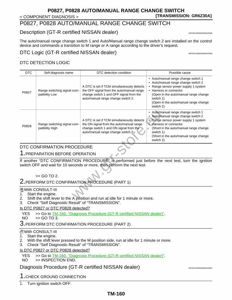
[TRANSMISSION: GR6Z30A]P0827, P0828 AUTO/MANUAL RANGE CHANGE SWITCH
< COMPONENT DIAGNOSIS >
P0827, P0828 AUTO/MANUAL RANGE CHANGE SWITCH
Description (GT-R certified NISSAN dealer) INFOID:0000000004019945
The auto/manual range change switch 1 and Auto/Manual range change switch 2 are installed on the controldevice and commands a transition to M range or A range according to the driver's request.
DTC Logic (GT-R certified NISSAN dealer) INFOID:0000000004019946
DTC DETECTION LOGIC
DTC CONFIRMATION PROCEDURE
1.PREPARATION BEFORE OPERATION
If another “DTC CONFIRMATION PROCEDURE” is performed just before the next test, turn the ignitionswitch OFF and wait for 10 seconds or more, then perform the next test.
>> GO TO 2.
2.PERFORM DTC CONFIRMATION PROCEDURE (PART 1)
With CONSULT-III1. Start the engine.2. Shift the shift lever to the A position and run at idle for 1 minute or more.3. Check “Self Diagnostic Result” of “TRANSMISSION”.Is DTC P0827 or DTC P0828 detected?YES >> Go to TM-160, "Diagnosis Procedure (GT-R certified NISSAN dealer)".NO >> GO TO 3.
3.PERFORM DTC CONFIRMATION PROCEDURE (PART 2)
With CONSULT-III1. Start the engine.2. With the shift lever pressed to the M position side, run at idle for 1 minute or more.3. Check “Self Diagnostic Result” of “TRANSMISSION”.Is DTC P0827 or DTC P0828 detected?YES >> Go to TM-160, "Diagnosis Procedure (GT-R certified NISSAN dealer)".NO >> INSPECTION END.
Diagnosis Procedure (GT-R certified NISSAN dealer) INFOID:0000000004019947
1.CHECK GROUND CONNECTION
1. Turn ignition switch OFF.
DTC Self-diagnosis name DTC detection condition Possible cause
P0827Range switching signal com-patibility Low
A DTC is set if TCM simultaneously detects the OFF signal from the auto/manual range change switch 1 and OFF signal from the auto/manual range change switch 2.
• Auto/manual range change switch 1• Auto/manual range change switch 2• Range sensor power supply 1 system• Harness or connector
(Open in the auto/manual range change switch 1)(Open in the auto/manual range change switch 2)
P0828Range switching signal com-patibility High
A DTC is set if TCM simultaneously detects the ON signal from the auto/manual range change switch 1 and ON signal from the auto/manual range change switch 2.
• Auto/manual range change switch 1• Auto/manual range change switch 2• Range sensor power supply 1 system• Harness or connector
(Short in the auto/manual range change switch 1)(Short in the auto/manual range change switch 2)
www.gtr-
store
.eu
TM-160

P0827, P0828 AUTO/MANUAL RANGE CHANGE SWITCH[TRANSMISSION: GR6Z30A]
C
E
F
G
H
I
J
K
L
M
A
B
M
N
O
P
< COMPONENT DIAGNOSIS >
T
2. Check ground connection B31. Refer to “Ground Inspection” in XX-XX, "*****".Is the inspection result normal?YES >> GO TO 2.NO >> Repair or replace damaged parts.
2.CHECK AUTO/MANUAL RANGE CHANGE SWITCH CIRCUIT (PART 1)
1. Disconnect TCM harness connectors.2. Check continuity between TCM vehicle side harness connector terminals.
Is the inspection result normal?YES >> GO TO 3.NO >> GO TO 4.
3.CHECK AUTO/MANUAL RANGE CHANGE SWITCH CIRCUIT (PART 2)
Check continuity between TCM vehicle side harness connector terminals and ground.
Is the inspection result normal?YES >> GO TO 7.NO >> GO TO 5.
4.CHECK AUTO/MANUAL RANGE CHANGE SWITCH
1. Disconnect control device harness connector.2. Check auto/manual range change switch. Refer to TM-162, "Component Inspection (Auto/Manual Range
Change Switch) (GT-R certified NISSAN dealer)".Is the inspection result normal?YES >> GO TO 5.NO >> Repair or replace damaged parts.
5.CHECK HARNESS BETWEEN TCM AND CONTROL DEVICE (AUTO/MANUAL RANGE CHANGESWITCH) (PART 1)
Check continuity between TCM vehicle side harness connector terminals and control device vehicle side har-ness connector terminals.
Is the inspection result normal?YES >> GO TO 6.NO >> Repair or replace damaged parts.
6.CHECK HARNESS BETWEEN TCM AND CONTROL DEVICE (AUTO/MANUAL RANGE CHANGE
TCM vehicle side harness connectorCondition Continuity
Connector Terminal
B45
25 23The shift lever is pressed onto the M position side Not existed
Other than the above Existed
25 28The shift lever is pressed onto the M position side Existed
Other than the above Not existed
TCM vehicle side harness connectorGround Continuity
Connector Terminal
B45
23
Ground Not existed25
28
TCM vehicle side harness connector Control device vehicle side harness connectorContinuity
Connector Terminal Connector Terminal
B45
23
B20
20
Existed25 16
28 24
www.gtr-
store
.eu
TM-161

[TRANSMISSION: GR6Z30A]P0827, P0828 AUTO/MANUAL RANGE CHANGE SWITCH
< COMPONENT DIAGNOSIS >SWITCH) (PART 2)
Check continuity between TCM vehicle side harness connector terminals and ground.
Is the inspection result normal?YES >> GO TO 7.NO >> Repair or replace damaged parts.
7.CHECK INTERMITTENT INCIDENT
Refer to XX-XX, "*****".
>> INSPECTION END
Component Inspection (Auto/Manual Range Change Switch) (GT-R certified NISSAN dealer) INFOID:0000000004019948
1.CHECK AUTO/MANUAL RANGE CHANGE SWITCH
Check continuity between control device harness connector terminals.
Is the inspection result normal?YES >> INSPECTION ENDNO >> Repair or replace damaged parts.
TCM vehicle side harness connectorGround Continuity
Connector Terminal
B45
23
Ground Not existed25
28
TCM vehicle side harness connectorCondition Continuity
Connector Terminal
B20
16 20The shift lever is pressed onto the M position side Not existed
Other than the above Existed
16 24The shift lever is pressed onto the M position side Existed
Other than the above Not existed
www.gtr-
store
.eu
TM-162

P0840 CLUTCH A PRESSURE SENSOR[TRANSMISSION: GR6Z30A]
C
E
F
G
H
I
J
K
L
M
A
B
M
N
O
P
< COMPONENT DIAGNOSIS >
T
P0840 CLUTCH A PRESSURE SENSOR
Description (GT-R certified NISSAN dealer) INFOID:0000000004019949
• The clutch A pressure sensor is installed on the front control module and detects the pressure applied to theclutch A.
• The clutch A pressure sensor converts the pressure applied to the clutch A into output voltage and transmitsthe signal to TCM. TCM uses this signal in calculations for control switching or other functions.
• The clutch A pressure sensor output voltage varies depending on the pressure variations. The voltageincreases as the pressure increases.
DTC Logic (GT-R certified NISSAN dealer) INFOID:0000000004019950
DTC DETECTION LOGICNOTE:If DTC P0700 is detected, first diagnose the DTC P0700. Refer to TM-58, "DTC Logic (GT-R certified NISSANdealer)".
DTC CONFIRMATION PROCEDURE
1.PREPARATION BEFORE OPERATION (PART 1)
If another “DTC CONFIRMATION PROCEDURE” is performed just before the next test, turn the ignitionswitch OFF and wait for 10 seconds or more, then perform the next test.
>> GO TO 2.
2.PREPARATION BEFORE OPERATION (PART 2)
With CONSULT-III1. Turn the ignition switch ON.2. Select “FLUID TEMP” in “Data Monitor”.
Without CONSULT-III1. Turn the ignition switch ON.2. Check “TRANS OIL TEMP” on multi-function display.Is the oil temperature −10°C (14°F) or more?YES >> GO TO 3.NO >> Warm up the transmission.
3.PERFORM DTC CONFIRMATION PROCEDURE
With CONSULT-III1. Turn the ignition switch ON.2. Shift the shift lever to the N position.
CAUTION:No shift position indicator in the combination meter blinks.
3. Start the engine.4. With the shift lever in the N position and run at idle for 5 seconds or more.5. Check “Self Diagnostic Result” of “TRANSMISSION”.
Without CONSULT-III1. Turn the ignition switch ON.2. Shift the shift lever to the N position.
CAUTION:No shift position indicator in the combination meter blinks.
3. Start the engine.
DTC Self-diagnosis name DTC detection condition Possible cause
P0840Clutch A pressure sensor voltage
• A DTC is set if the clutch A pressure sen-sor voltage value received by TCM is more than 4,700 mV.
• A DTC is set if the clutch A pressure sen-sor voltage value received by TCM is less than 90 mV.
• Clutch A pressure sensor• TCM• Harness or connector
(Open or short in the clutch A pressure sensor circuit)
www.gtr-
store
.eu
TM-163

[TRANSMISSION: GR6Z30A]P0840 CLUTCH A PRESSURE SENSOR
< COMPONENT DIAGNOSIS >4. With the shift lever in the N position and run at idle for 5 seconds or more.5. Check self-diagnosis.Is DTC P0840 detected?YES >> Go to TM-164, "Diagnosis Procedure (GT-R certified NISSAN dealer)".NO >> INSPECTION END
Diagnosis Procedure (GT-R certified NISSAN dealer) INFOID:0000000004019951
1.CHECK GROUND CONNECTION
1. Turn ignition switch OFF.2. Check ground connections B31 and ground cable connections. Refer to “Ground Inspection” in XX-XX,
"*****".Is the inspection result normal?YES >> GO TO 2.NO >> Repair or replace damaged parts.
2.CHECK TCM OUTPUT SIGNAL CIRCUIT
Check voltage between TCM vehicle side harness connector terminals.
Is the inspection result normal?YES >> GO TO 4.NO >> GO TO 3.
3.CHECK TCM POWER SUPPLY
Refer to TM-172, "Diagnosis Procedure (GT-R certified NISSAN dealer)".Is the inspection result normal?YES >> Replace TCM. Refer to TM-270, "Exploded View (GT-R certified NISSAN dealer)".NO >> Repair or replace damaged parts.
4.CHECK TCM INPUT SIGNAL CIRCUIT
1. Start engine.2. Check voltage between TCM vehicle side harness connector terminals.
Is the inspection result normal?YES >> GO TO 5.NO >> GO TO 6.
5.CHECK INTERMITTENT INCIDENT
Refer to XX-XX, "*****".
>> INSPECTION END
6.CHECK HARNESS BETWEEN TCM AND TRANSMISSION (CLUTCH A PRESSURE SENSOR) (PART 1)
1. Turn ignition switch OFF.2. Disconnect TCM harness connectors and transmission unit harness connectors.
TCM vehicle side harness connectorCondition Voltage (Approx.)
Connector Terminal
B47 97 4Ignition switch ON 5 V
Ignition switch OFF 0 V
TCM vehicle side harness connectorCondition Voltage (Approx.)
Connector Terminal
B47 98 4
Engine running
Shift lever: P, R, or N position
0.38 – 0.64 VWhile driving
1st gear, 3rd gear, 5th gear
www.gtr-
store
.eu
TM-164

P0840 CLUTCH A PRESSURE SENSOR[TRANSMISSION: GR6Z30A]
C
E
F
G
H
I
J
K
L
M
A
B
M
N
O
P
< COMPONENT DIAGNOSIS >
T
3. Check continuity between TCM vehicle side harness connector terminals and transmission unit vehicleside harness connector terminals.
Is the inspection result normal?YES >> GO TO 7.NO >> Repair or replace damaged parts.
7.CHECK HARNESS BETWEEN TCM AND TRANSMISSION (CLUTCH A PRESSURE SENSOR) (PART 2)
Check continuity between TCM vehicle side harness connector terminals and ground.
Is the inspection result normal?YES >> GO TO 8.NO >> Repair or replace damaged parts.
8.CHECK INTERMITTENT INCIDENT
Refer to XX-XX, "*****".Is the inspection result normal?YES >> Replace transmission assembly. Refer to TM-291, "Exploded View (GT-R certified NISSAN
dealer)".NO >> Repair or replace damaged parts.
TCM vehicle side harness connector Transmission unit vehicle side harness connectorContinuity
Connector Terminal Connector Terminal
B47
97
B50
40
Existed98 41
99 47
TCM vehicle side harness connectorGround Continuity
Connector Terminal
B47
97
Ground Not existed98
99
www.gtr-
store
.eu
TM-165

[TRANSMISSION: GR6Z30A]P0845 CLUTCH B PRESSURE SENSOR
< COMPONENT DIAGNOSIS >
P0845 CLUTCH B PRESSURE SENSOR
Description (GT-R certified NISSAN dealer) INFOID:0000000004019952
• The clutch B pressure sensor is installed on the front control module and detects the pressure applied to theclutch B.
• The clutch B pressure sensor converts the pressure applied to the clutch B into output voltage and transmitsthe signal to TCM. TCM uses this signal in calculations for control switching or other functions.
• The clutch B pressure sensor output voltage varies depending on the pressure variations. The voltageincreases as the pressure increases.
DTC Logic (GT-R certified NISSAN dealer) INFOID:0000000004019953
DTC DETECTION LOGICNOTE:If DTC P0700 is detected, first diagnose the DTC P0700. Refer to TM-58, "DTC Logic (GT-R certified NISSANdealer)".
DTC CONFIRMATION PROCEDURE
1.PREPARATION BEFORE OPERATION (PART 1)
If another “DTC CONFIRMATION PROCEDURE” is performed just before the next test, turn the ignitionswitch OFF and wait for 10 seconds or more, then perform the next test.
>> GO TO 2.
2.PREPARATION BEFORE OPERATION (PART 2)
With CONSULT-III1. Turn the ignition switch ON.2. Select “FLUID TEMP” in “Data Monitor”.
Without CONSULT-III1. Turn the ignition switch ON.2. Check “TRANS OIL TEMP” on multi-function display.Is the oil temperature −10°C (14°F) or more?YES >> GO TO 3.NO >> Warm up the transmission.
3.PERFORM DTC CONFIRMATION PROCEDURE
With CONSULT-III1. Turn the ignition switch ON.2. Shift the shift lever to the N position.
CAUTION:No shift position indicator in the combination meter blinks.
3. Start the engine.4. With the shift lever in the N position and run at idle for 5 seconds or more.5. Check “Self Diagnostic Result” of “TRANSMISSION”.
Without CONSULT-III1. Turn the ignition switch ON.2. Shift the shift lever to the N position.
CAUTION:No shift position indicator in the combination meter blinks.
3. Start the engine.
DTC Self-diagnosis name DTC detection condition Possible cause
P0845Clutch B pressure sensor voltage
• A DTC is set if the clutch B pressure sen-sor voltage value received by TCM is more than 4,700 mV.
• A DTC is set if the clutch B pressure sen-sor voltage value received by TCM is less than 90 mV.
• Clutch B pressure sensor• TCM• Harness or connector
(Open or short in the clutch B pressure sensor circuit)
www.gtr-
store
.eu
TM-166

P0845 CLUTCH B PRESSURE SENSOR[TRANSMISSION: GR6Z30A]
C
E
F
G
H
I
J
K
L
M
A
B
M
N
O
P
< COMPONENT DIAGNOSIS >
T
4. With the shift lever in the N position and run at idle for 5 seconds or more.5. Check self-diagnosis.Is DTC P0845 detected?YES >> Go to TM-167, "Diagnosis Procedure (GT-R certified NISSAN dealer)".NO >> INSPECTION END
Diagnosis Procedure (GT-R certified NISSAN dealer) INFOID:0000000004019954
1.CHECK GROUND CONNECTION
1. Turn ignition switch OFF.2. Check ground connections B31 and ground cable connections. Refer to “Ground Inspection” in XX-XX,
"*****".Is the inspection result normal?YES >> GO TO 2.NO >> Repair or replace damaged parts.
2.CHECK TCM OUTPUT SIGNAL CIRCUIT
Check voltage between TCM vehicle side harness connector terminals.
Is the inspection result normal?YES >> GO TO 4.NO >> GO TO 3.
3.CHECK TCM POWER SUPPLY
Refer to TM-172, "Diagnosis Procedure (GT-R certified NISSAN dealer)".Is the inspection result normal?YES >> Replace TCM. Refer to TM-270, "Exploded View (GT-R certified NISSAN dealer)".NO >> Repair or replace damaged parts.
4.CHECK TCM INPUT SIGNAL CIRCUIT
1. Start engine.2. Check voltage between TCM vehicle side harness connector terminals.
Is the inspection result normal?YES >> GO TO 5.NO >> GO TO 6.
5.CHECK INTERMITTENT INCIDENT
Refer to XX-XX, "*****".
>> INSPECTION END
6.CHECK HARNESS BETWEEN TCM AND TRANSMISSION (CLUTCH B PRESSURE SENSOR) (PART 1)
1. Turn ignition switch OFF.2. Disconnect TCM harness connectors and transmission unit harness connectors.
TCM vehicle side harness connectorCondition Voltage (Approx.)
Connector Terminal
B47 102 4Ignition switch ON 5 V
Ignition switch OFF 0 V
TCM vehicle side harness connectorCondition Voltage (Approx.)
Connector Terminal
B47 103 4
Engine running
Shift lever: P, R, or N position
0.38 – 0.64 VWhile driving
2nd gear, 4th gear, 6th gear
www.gtr-
store
.eu
TM-167

[TRANSMISSION: GR6Z30A]P0845 CLUTCH B PRESSURE SENSOR
< COMPONENT DIAGNOSIS >3. Check continuity between TCM vehicle side harness connector terminals and transmission unit vehicle
side harness connector terminals.
Is the inspection result normal?YES >> GO TO 7.NO >> Repair or replace damaged parts.
7.CHECK HARNESS BETWEEN TCM AND TRANSMISSION (CLUTCH B PRESSURE SENSOR) (PART 2)
Check continuity between TCM vehicle side harness connector terminals and ground.
Is the inspection result normal?YES >> GO TO 8.NO >> Repair or replace damaged parts.
8.CHECK INTERMITTENT INCIDENT
Refer to XX-XX, "*****".Is the inspection result normal?YES >> Replace transmission assembly. Refer to TM-291, "Exploded View (GT-R certified NISSAN
dealer)".NO >> Repair or replace damaged parts.
TCM vehicle side harness connector Transmission unit vehicle side harness connectorContinuity
Connector Terminal Connector Terminal
B47
102
B50
51
Existed103 52
104 53
TCM vehicle side harness connectorGround Continuity
Connector Terminal
B47
102
Ground Not existed103
104
www.gtr-
store
.eu
TM-168

P0872, P0873 LINE PRESSURE SENSOR[TRANSMISSION: GR6Z30A]
C
E
F
G
H
I
J
K
L
M
A
B
M
N
O
P
< COMPONENT DIAGNOSIS >
T
P0872, P0873 LINE PRESSURE SENSOR
Description (GT-R certified NISSAN dealer) INFOID:0000000004019955
• The line pressure sensor is installed on the actuator control module and detects the line pressure.• The line pressure sensor converts the line pressure into output voltage and transmits the signal to TCM.
TCM uses this signal in calculations for control switching or other functions.• The line pressure sensor output voltage varies depending on the pressure variations. The voltage increases
as the pressure increases.
DTC Logic (GT-R certified NISSAN dealer) INFOID:0000000004019956
DTC DETECTION LOGICNOTE:If DTC P0700 is detected, first diagnose the DTC P0700. Refer to TM-58, "DTC Logic (GT-R certified NISSANdealer)".
DTC CONFIRMATION PROCEDURE
1.PREPARATION BEFORE OPERATION (PART 1)
If another “DTC CONFIRMATION PROCEDURE” is performed just before the next test, turn the ignitionswitch OFF and wait for 10 seconds or more, then perform the next test.
>> GO TO 2.
2.PREPARATION BEFORE OPERATION (PART 2)
With CONSULT-III1. Turn the ignition switch ON.2. Select “FLUID TEMP” in “Data Monitor”.Is the oil temperature −10°C (14°F) or more?YES >> GO TO 3.NO >> Warm up the transmission.
3.PERFORM DTC CONFIRMATION PROCEDURE
With CONSULT-III1. Start the engine.2. With the shift lever in the P position, and run at idle for 5 seconds or more.3. Check “Self Diagnostic Result” of TRANSMISSION.Is DTC P0872 or DTC P0873 detected?YES >> Go to TM-169, "Diagnosis Procedure (GT-R certified NISSAN dealer)".NO >> INSPECTION END
Diagnosis Procedure (GT-R certified NISSAN dealer) INFOID:0000000004019957
1.CHECK GROUND CONNECTION
1. Turn ignition switch OFF.2. Check ground connections B31 and ground cable connections. Refer to “Ground Inspection” in XX-XX,
"*****".Is the inspection result normal?YES >> GO TO 2.
DTC Self-diagnosis name DTC detection condition Possible cause
P0872Line pressure sensor voltage system Low
A DTC is set if the line pressure sensor volt-age value received by TCM is less than 90 mV.
• Line pressure sensor• Harness or connector
(Open in the line pressure sensor circuit)
P0873Line pressure sensor voltage system High
A DTC is set if the line pressure sensor volt-age value received by TCM is more than 4,700 mV.
• Line pressure sensor• Harness or connector
(Short in the line pressure sensor circuit)
www.gtr-
store
.eu
TM-169

[TRANSMISSION: GR6Z30A]P0872, P0873 LINE PRESSURE SENSOR
< COMPONENT DIAGNOSIS >NO >> Repair or replace damaged parts.
2.CHECK TCM OUTPUT SIGNAL CIRCUIT
Check voltage between TCM vehicle side harness connector terminals.
Is the inspection result normal?YES >> GO TO 3.NO >> Go to TM-194, "Diagnosis Procedure (GT-R certified NISSAN dealer)".
3.CHECK TCM INPUT SIGNAL CIRCUIT
1. Start engine.2. Check voltage between TCM vehicle side harness connector terminals.
Is the inspection result normal?YES >> GO TO 4.NO >> GO TO 5.
4.CHECK INTERMITTENT INCIDENT
Refer to XX-XX, "*****".
>> INSPECTION END
5.CHECK HARNESS BETWEEN TCM AND TRANSMISSION (LINE PRESSURE SENSOR) (PART 1)
1. Turn ignition switch OFF.2. Disconnect TCM harness connectors and transmission unit harness connectors.3. Check continuity between TCM vehicle side harness connector terminals and transmission unit vehicle
side harness connector terminals.
Is the inspection result normal?YES >> GO TO 6.NO >> Repair or replace damaged parts.
6.CHECK HARNESS BETWEEN TCM AND TRANSMISSION (LINE PRESSURE SENSOR) (PART 2)
Check continuity between TCM vehicle side harness connector terminals and ground.
TCM vehicle side harness connectorCondition Voltage (Approx.)
Connector Terminal
B46 73 4Ignition switch ON 5 V
Ignition switch OFF 0 V
TCM vehicle side harness connectorCondition Voltage (Approx.)
Connector Terminal
B46 77 4Engine running
• Shift lever: P, N position• At idle
0.84 – 1.97 V
TCM vehicle side harness connector Transmission unit vehicle side harness connectorContinuity
Connector Terminal Connector Terminal
B46
73
B49
35
Existed77 12
80 19
TCM vehicle side harness connectorGround Continuity
Connector Terminal
B46
73
Ground Not existed77
80
www.gtr-
store
.eu
TM-170

P0872, P0873 LINE PRESSURE SENSOR[TRANSMISSION: GR6Z30A]
C
E
F
G
H
I
J
K
L
M
A
B
M
N
O
P
< COMPONENT DIAGNOSIS >
T
Is the inspection result normal?YES >> GO TO 7.NO >> Repair or replace damaged parts.
7.CHECK INTERMITTENT INCIDENT
Refer to XX-XX, "*****".Is the inspection result normal?YES >> Replace transmission assembly. Refer to TM-291, "Exploded View (GT-R certified NISSAN
dealer)".NO >> Repair or replace damaged parts.
www.gtr-
store
.eu
TM-171

[TRANSMISSION: GR6Z30A]P0882 TCM POWER SUPPLY
< COMPONENT DIAGNOSIS >
P0882 TCM POWER SUPPLY
Description (GT-R certified NISSAN dealer) INFOID:0000000004019958
The power supply distributes the power to the neutral signal transmitted to each solenoid, starter relay andECM.
DTC Logic (GT-R certified NISSAN dealer) INFOID:0000000004019959
DTC DETECTION LOGICNOTE:• If DTC P0700 is detected, first diagnose the DTC P0700. Refer to TM-58, "DTC Logic (GT-R certified NIS-
SAN dealer)".• If DTC P0705 is detected, first diagnose the DTC P0705. Refer to TM-62, "DTC Logic (GT-R certified NIS-
SAN dealer)".
DTC CONFIRMATION PROCEDURE
1.PREPARATION BEFORE OPERATION
If another “DTC CONFIRMATION PROCEDURE” is performed just before the next test, turn the ignitionswitch OFF and wait for 10 seconds or more, then perform the next test.
>> GO TO 2.
2.PERFORM DTC CONFIRMATION PROCEDURE
With CONSULT-III1. Start the engine and run at idle for 5 seconds or more.2. Check “Self Diagnostic Result” of “TRANSMISSION”.
Without CONSULT-III1. Start the engine and run at idle for 5 seconds or more.2. Check self-diagnosis.Is DTC P0882 detected?YES >> Go to TM-172, "Diagnosis Procedure (GT-R certified NISSAN dealer)".NO >> INSPECTION END
Diagnosis Procedure (GT-R certified NISSAN dealer) INFOID:0000000004019960
1.CHECK GROUND CONNECTION
1. Turn ignition switch OFF.2. Check ground connections B31. Refer to “Ground Inspection” in XX-XX, "*****".Is the inspection result normal?YES >> GO TO 2.NO >> Repair or replace damaged parts.
2.CHECK TCM INPUT SIGNAL CIRCUIT
Check voltage between TCM vehicle side harness connector terminals.
DTC Self-diagnosis name DTC detection condition Possible cause
P0882Power supply voltage sys-tem
A DTC is set if the power voltage input to TCM is less than 10.5 V.
• Battery voltage drop• TCM relay• Harness or connector
(Open in the power supply circuit)
www.gtr-
store
.eu
TM-172

P0882 TCM POWER SUPPLY[TRANSMISSION: GR6Z30A]
C
E
F
G
H
I
J
K
L
M
A
B
M
N
O
P
< COMPONENT DIAGNOSIS >
T
Is the inspection result normal?YES >> GO TO 7.NO >> GO TO 3.
3.CHECK HARNESS BETWEEN TCM AND TCM RELAY (PART 1)
1. Disconnect TCM harness connectors and TCM relay harness connector.2. Check continuity between TCM vehicle side harness connector terminals and TCM relay vehicle side har-
ness connector terminals.
Is the inspection result normal?YES >> GO TO 4.NO >> Repair or replace damaged parts.
4.CHECK HARNESS BETWEEN TCM AND TCM RELAY (PART 2)
Check continuity between TCM vehicle side harness connector terminals and ground.
Is the inspection result normal?YES >> GO TO 5.NO >> Repair or replace damaged parts.
5.CHECK TCM RELAY
Check TCM relay. Refer to TM-174, "Component Inspection (TCM Relay) (GT-R certified NISSAN dealer)".Is the inspection result normal?YES >> GO TO 6.NO >> Repair or replace damaged parts.
6.DETECT MALFUNCTIONING ITEM
Check the following. Refer to XX-XX, "*****".• 20A fuse (No. 36, located in the fuse and fusible link block)• Fuse and fusible link block• Harness for open or short TCM relay and battery
TCM vehicle side harness connectorCondition Voltage (Approx.)
Connector Terminal
B45
1 4Ignition switch ON
Battery voltage (11 – 14 V)
Ignition switch OFF 0 V
5 4Ignition switch ON
Battery voltage (11 – 14 V)
Ignition switch OFF 0 V
14 4
Ignition switch ON 0 V
Ignition switch OFFBattery voltage
(11 – 14 V)
TCM vehicle side harness connector TCM relay vehicle side harness connectorContinuity
Connector Terminal Connector Terminal
B45
1
B546
Existed5
14 1
TCM vehicle side harness connectorGround Continuity
Connector Terminal
B45
1
Ground Not existed5
14
www.gtr-
store
.eu
TM-173

[TRANSMISSION: GR6Z30A]P0882 TCM POWER SUPPLY
< COMPONENT DIAGNOSIS >Is the inspection result normal?YES >> GO TO 7.NO >> Repair or replace damaged parts.
7.CHECK INTERMITTENT INCIDENT
Refer to XX-XX, "*****".
>> INSPECTION END
Component Inspection (TCM Relay) (GT-R certified NISSAN dealer) INFOID:0000000004019961
1.CHECK TCM RELAY
Check continuity between TCM relay connector terminals.CAUTION:• When applying voltage, use a fuse.• Never cause a short circuit.
Is the inspection result normal?YES >> INSPECTION ENDNO >> Replace TCM relay.
TCM relay connectorCondition Continuity
Connector Terminal
B54
3 5Apply battery voltage between terminals 1 and 2 Existed
Other than the above Not existed
6 7Apply battery voltage between terminals 1 and 2 Existed
Other than the above Not existed
www.gtr-
store
.eu
TM-174

P1705 ACCELERATOR PEDAL POSITION SIGNAL[TRANSMISSION: GR6Z30A]
C
E
F
G
H
I
J
K
L
M
A
B
M
N
O
P
< COMPONENT DIAGNOSIS >
T
P1705 ACCELERATOR PEDAL POSITION SIGNAL
Description (GT-R certified NISSAN dealer) INFOID:0000000004019962
• The accelerator pedal position sensor is installed on the upper section of the accelerator pedal assemblyand detects the depressing amount of the accelerator pedal. The accelerator pedal position sensor convertsthe depressing amount of the accelerator pedal into voltage signal and transmits it to ECM. ECM transmitsthe signal to TCM via the CAN communication.
• TCM selects the driving gear using the gear shift line and corrects the operation of the clutches and clutchactuators based on the signal.
DTC Logic (GT-R certified NISSAN dealer) INFOID:0000000004019963
DTC DETECTION LOGICNOTE:If DTC P0700 is detected, first diagnose the DTC P0700. Refer to TM-58, "DTC Logic (GT-R certified NISSANdealer)".
DTC CONFIRMATION PROCEDURE
1.PREPARATION BEFORE OPERATION
If another “DTC CONFIRMATION PROCEDURE” is performed just before the next test, turn the ignitionswitch OFF and wait for 10 seconds or more, then perform the next test.
>> GO TO 2.
2.PERFORM DTC CONFIRMATION PROCEDURE
With CONSULT-III1. Start the engine and run at idle for 5 seconds or more.2. Check “Self Diagnostic Result” of “TRANSMISSION”.
Without CONSULT-III1. Start the engine and run at idle for 5 seconds or more.2. Check self-diagnosis.Is DTC P1705 detected?YES >> Go to TM-175, "Diagnosis Procedure (GT-R certified NISSAN dealer)".NO >> INSPECTION END
Diagnosis Procedure (GT-R certified NISSAN dealer) INFOID:0000000004019964
1.CHECK DTC WITH ECM
With CONSULT-III1. Turn ignition switch ON.2. Check “Self Diagnostic Result” of “ENGINE”.Is DTC detected?YES >> Check DTC Detected Item. Refer to XX-XX, "*****".NO >> GO TO 2.
2.CHECK INTERMITTENT INCIDENT
Refer to XX-XX, "*****".
>> INSPECTION END
DTC Self-diagnosis name DTC detection condition Possible cause
P1705Throttle position CAN signal compatibility
A DTC is set if TCM detects a difference be-tween 2 signals of the throttle position (CAN signal).
• Accelerator pedal position sensor• ECM• Harness or connector
(Open or short in the accelerator pedal po-sition sensor signal circuit)
www.gtr-
store
.eu
TM-175

[TRANSMISSION: GR6Z30A]P2713 AXIS B FEED PRESSURE SOLENOID VALVE
< COMPONENT DIAGNOSIS >
P2713 AXIS B FEED PRESSURE SOLENOID VALVE
Description (GT-R certified NISSAN dealer) INFOID:0000000004019965
• The axis B feed pressure solenoid valve is installed on the actuator control module and builds up the sourcepressure for the gear operation actuators for odd number gears and reverse gear and for the clutch B pres-sure solenoid valve based on the signals from TCM. The solenoid valves adjust the source pressure to drivethe gears and clutches.
• The axis B feed pressure solenoid valve is a N/L type (normal low) in which no control oil pressure is built upwhen no current flows through the coil.
DTC Logic (GT-R certified NISSAN dealer) INFOID:0000000004019966
DTC DETECTION LOGICNOTE:If DTC P0700 is displayed, perform the diagnosis of DTC P0700 first. Refer to TM-58, "DTC Logic (GT-R cer-tified NISSAN dealer)".
DTC CONFIRMATION PROCEDURE
1.PREPARATION BEFORE OPERATION
If another “DTC CONFIRMATION PROCEDURE” is performed just before the next test, turn the ignitionswitch OFF and wait for 10 seconds or more, then perform the next test.
>> GO TO 2.
2.PERFORM DTC CONFIRMATION PROCEDURE
With CONSULT-III1. Turn the ignition switch ON.2. Shift the shift lever to the N position.
CAUTION:No shift position indicator in the combination meter blinks.
3. Start the engine.4. With the shift lever in the N position, and run at idle for 5 seconds or more.5. Check “Self Diagnostic Result” of “TRANSMISSION”.
Without CONSULT-III1. Turn the ignition switch ON.2. Shift the shift lever to the N position.
CAUTION:No shift position indicator in the combination meter blinks.
3. Start the engine.4. With the shift lever in the N position, and run at idle for 5 seconds or more.5. Check self-diagnosis.Is DTC P2713 detected?YES >> Go to TM-176, "Diagnosis Procedure (GT-R certified NISSAN dealer)".NO >> INSPECTION END
Diagnosis Procedure (GT-R certified NISSAN dealer) INFOID:0000000004019967
1.CHECK GROUND CONNECTION
1. Turn ignition switch OFF.
DTC Self-diagnosis name DTC detection condition Possible cause
P2713Axis B feed pressure sole-noid valve current
A DTC is set if the axis B feed pressure so-lenoid valve monitor current value is less than 0.2 A when the axis B feed pressure so-lenoid valve target current value is more than 0.38 A.
• Axis B feed pressure solenoid valve• Harness or connector
(Open or short in the axis B feed pressure solenoid valve circuit)
www.gtr-
store
.eu
TM-176

P2713 AXIS B FEED PRESSURE SOLENOID VALVE[TRANSMISSION: GR6Z30A]
C
E
F
G
H
I
J
K
L
M
A
B
M
N
O
P
< COMPONENT DIAGNOSIS >
T
2. Check ground connections B31 and ground cable connections. Refer to “Ground Inspection” in XX-XX,"*****".
Is the inspection result normal?YES >> GO TO 2.NO >> Repair or replace damaged parts.
2.CHECK AXIS B FEED PRESSURE SOLENOID VALVE CIRCUIT (PART 1)
1. Disconnect TCM harness connectors.2. Check resistance between TCM vehicle side harness connector terminals.
Is the inspection result normal?YES >> GO TO 3.NO >> GO TO 4.
3.CHECK AXIS B FEED PRESSURE SOLENOID VALVE CIRCUIT (PART 2)
Check continuity between TCM vehicle side harness connector terminals and ground.
Is the inspection result normal?YES >> GO TO 7.NO >> GO TO 4.
4.CHECK AXIS B FEED PRESSURE SOLENOID VALVE
1. Disconnect transmission unit harness connectors.2. Check axis B feed pressure solenoid valve. Refer to TM-178, "Component Inspection (Axis B Feed Pres-
sure Solenoid Valve) (GT-R certified NISSAN dealer)".Is the inspection result normal?YES >> GO TO 5.NO >> Repair or replace damaged parts.
5.CHECK HARNESS BETWEEN TCM AND TRANSMISSION (AXIS B FEED PRESSURE SOLENOIDVALVE) (PART 1)
Check continuity between TCM vehicle side harness connector terminals and transmission unit vehicle sideharness connector terminals.
Is the inspection result normal?YES >> GO TO 6.NO >> Repair or replace damaged parts.
6.CHECK HARNESS BETWEEN TCM AND TRANSMISSION (AXIS B FEED PRESSURE SOLENOIDVALVE) (PART 2)
Check continuity between TCM vehicle side harness connector terminals and ground.
TCM vehicle side harness connectorCondition
Resistance (Ap-prox.)Connector Terminal
B46 59 64
Transmission oil temperature: 20°C (68°F) 3.8 – 4.4 Ω
Transmission oil temperature: 50°C (122°F) 4.3 – 5.0 Ω
Transmission oil temperature: 80°C (176°F) 4.7 – 5.4 Ω
TCM vehicle side harness connectorGround Continuity
Connector Terminal
B4659
Ground Not existed64
TCM vehicle side harness connector Transmission unit vehicle side harness connectorContinuity
Connector Terminal Connector Terminal
B4659
B4921
Existed64 22
www.gtr-
store
.eu
TM-177

[TRANSMISSION: GR6Z30A]P2713 AXIS B FEED PRESSURE SOLENOID VALVE
< COMPONENT DIAGNOSIS >
Is the inspection result normal?YES >> GO TO 7.NO >> Repair or replace damaged parts.
7.CHECK INTERMITTENT INCIDENT
Refer to XX-XX, "*****".
>> INSPECTION END
Component Inspection (Axis B Feed Pressure Solenoid Valve) (GT-R certified NIS-SAN dealer) INFOID:0000000004019968
1.CHECK AXIS B FEED PRESSURE SOLENOID VALVE (PART 1)
Check the resistance between transmission unit harness connector terminals.
Is the inspection result normal?YES >> GO TO 2.NO >> Repair or replace damaged parts.
2.CHECK AXIS B FEED PRESSURE SOLENOID VALVE (PART 2)
Check continuity between transmission unit harness connector terminal and ground.
Is the inspection result normal?YES >> INSPECTION ENDNO >> Repair or replace damaged parts.
TCM vehicle side harness connectorGround Continuity
Connector Terminal
B4659
Ground Not existed64
Transmission unit harness connectorCondition
Resistance (Ap-prox.)Connector Terminal
B49 21 22
Transmission oil temperature: 20°C (68°F) 3.8 – 4.4 Ω
Transmission oil temperature: 50°C (122°F) 4.3 – 5.0 Ω
Transmission oil temperature: 80°C (176°F) 4.7 – 5.4 Ω
Transmission unit harness connectorGround Continuity
Connector Terminal
B4921
Ground Not existed22
www.gtr-
store
.eu
TM-178

P2714 AXIS B FEED PRESSURE SOLENOID VALVE FUNCTION[TRANSMISSION: GR6Z30A]
C
E
F
G
H
I
J
K
L
M
A
B
M
N
O
P
< COMPONENT DIAGNOSIS >
T
P2714 AXIS B FEED PRESSURE SOLENOID VALVE FUNCTION
Description (GT-R certified NISSAN dealer) INFOID:0000000004019969
This solenoid valve builds up the source pressure for the gear operation actuators for odd number gears andreverse gear and for the clutch B solenoid valve based on the signals from TCM. The solenoid valves adjustthe source pressure to drive the gears and clutches.
DTC Logic (GT-R certified NISSAN dealer) INFOID:0000000004019970
DTC DETECTION LOGICNOTE:If DTC P0845 is detected, first diagnose DTC P0845. Refer to TM-166, "DTC Logic (GT-R certified NISSANdealer)".
DTC CONFIRMATION PROCEDURE
1.PREPARATION BEFORE OPERATION
If another “DTC CONFIRMATION PROCEDURE” is performed just before the next test, turn the ignitionswitch OFF and wait for 10 seconds or more, then perform the next test.
>> GO TO 2.
2.PERFORM DTC CONFIRMATION PROCEDURE
With CONSULT-III1. Turn the ignition switch ON.2. Shift the shift lever to the P position.3. Start the engine.4. With the shift lever in the P position, and run at idle for 1 minute or more.5. Check “Self Diagnostic Result” of “TRANSMISSION”.
Without CONSULT-III1. Turn the ignition switch ON.2. Shift the shift lever to the P position.3. Start the engine.4. With the shift lever in the P position, and run at idle for 1 minute or more.5. Check self-diagnosis.Is DTC P2714 detected?YES >> Go to TM-179, "Diagnosis Procedure (GT-R certified NISSAN dealer)".NO >> INSPECTION END
Diagnosis Procedure (GT-R certified NISSAN dealer) INFOID:0000000004019971
1.CHECK AXIS B FEED PRESSURE SOLENOID VALVE CIRCUIT
Refer to TM-176, "Diagnosis Procedure (GT-R certified NISSAN dealer)".Is the inspection result normal?YES >> GO TO 2.
DTC Self-diagnosis name DTC detection condition Possible cause
P2714Axis B feed pressure sole-noid valve function
• A DTC is set if the clutch B pressure sen-sor value is less than 0.4 MPa (4.08 kg/
cm2, 58 psi) when the axis B feed pressure
target value is 0.4 MPa (4.08 kg/cm2, 58 psi) or more.
• A DTC is set if the clutch B pressure sen-sor value is more than 0.2 MPa (2.04 kg/
cm2, 29 psi) when the axis B feed pressure
target value is 0.1 MPa (1.02 kg/cm2, 14.5 psi) or less.
• Axis B feed pressure solenoid valve• Clutch B solenoid valve• Clutch B pressure sensor• Clutch B oil passage• Harness or connector
(Open or short in the axis B feed pressure solenoid valve circuit)(Open or short in the clutch B solenoid valve circuit)(Open or short in the clutch B pressure sensor circuit)
www.gtr-
store
.eu
TM-179
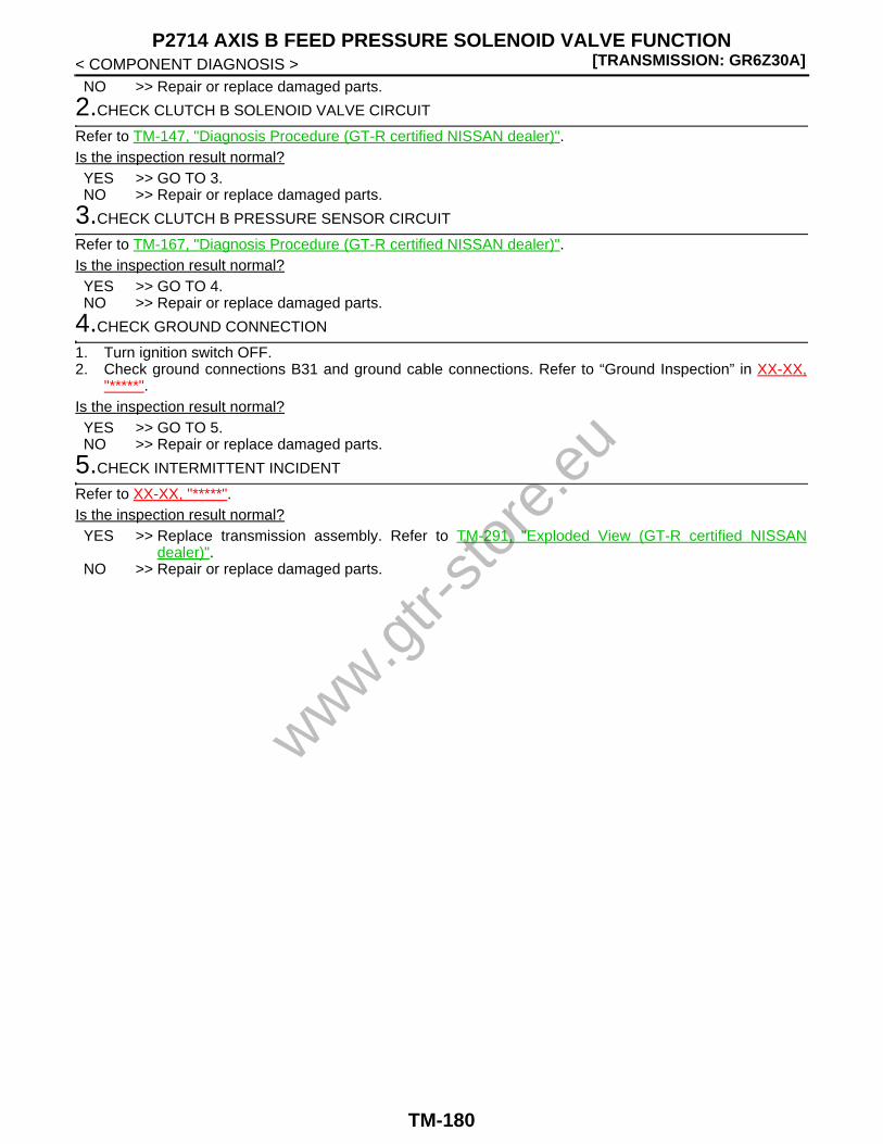
[TRANSMISSION: GR6Z30A]P2714 AXIS B FEED PRESSURE SOLENOID VALVE FUNCTION
< COMPONENT DIAGNOSIS >NO >> Repair or replace damaged parts.
2.CHECK CLUTCH B SOLENOID VALVE CIRCUIT
Refer to TM-147, "Diagnosis Procedure (GT-R certified NISSAN dealer)".Is the inspection result normal?YES >> GO TO 3.NO >> Repair or replace damaged parts.
3.CHECK CLUTCH B PRESSURE SENSOR CIRCUIT
Refer to TM-167, "Diagnosis Procedure (GT-R certified NISSAN dealer)".Is the inspection result normal?YES >> GO TO 4.NO >> Repair or replace damaged parts.
4.CHECK GROUND CONNECTION
1. Turn ignition switch OFF.2. Check ground connections B31 and ground cable connections. Refer to “Ground Inspection” in XX-XX,
"*****".Is the inspection result normal?YES >> GO TO 5.NO >> Repair or replace damaged parts.
5.CHECK INTERMITTENT INCIDENT
Refer to XX-XX, "*****".Is the inspection result normal?YES >> Replace transmission assembly. Refer to TM-291, "Exploded View (GT-R certified NISSAN
dealer)".NO >> Repair or replace damaged parts.
www.gtr-
store
.eu
TM-180

P2722 LUBRICATING FLOW SOLENOID VALVE[TRANSMISSION: GR6Z30A]
C
E
F
G
H
I
J
K
L
M
A
B
M
N
O
P
< COMPONENT DIAGNOSIS >
T
P2722 LUBRICATING FLOW SOLENOID VALVE
Description (GT-R certified NISSAN dealer) INFOID:0000000004019974
• The lubricating flow solenoid valve is installed on the front control module and controls the lubricating flow ofthe clutches A and B with the signals from TCM. This subsequently controls the lubricating flow of the geartrain.
• The lubricating flow solenoid valve is a N/H type (normal high) in which control oil pressure is built up whenno current flows through the coil.
DTC Logic (GT-R certified NISSAN dealer) INFOID:0000000004019975
DTC DETECTION LOGICNOTE:If DTC P0700 is detected, first diagnose the DTC P0700. Refer to TM-58, "DTC Logic (GT-R certified NISSANdealer)".
DTC CONFIRMATION PROCEDURE
1.PREPARATION BEFORE OPERATION
If another “DTC CONFIRMATION PROCEDURE” is performed just before the next test, turn the ignitionswitch OFF and wait for 10 seconds or more, then perform the next test.
>> GO TO 2.
2.PERFORM DTC CONFIRMATION PROCEDURE
With CONSULT-III1. Start the engine.2. Shift the shift lever to the P position and run at idle for 5 seconds or more.3. Check “Self Diagnostic Result” of “TRANSMISSION”.
Without CONSULT-III1. Start the engine.2. Shift the shift lever to the P position and run at idle for 5 seconds or more.3. Check self-diagnosis.Is DTC P2722 detected?YES >> Go to TM-181, "Diagnosis Procedure (GT-R certified NISSAN dealer)".NO >> INSPECTION END
Diagnosis Procedure (GT-R certified NISSAN dealer) INFOID:0000000004019976
1.CHECK GROUND CONNECTION
1. Turn ignition switch OFF.2. Check ground connections B31 and ground cable connections. Refer to “Ground Inspection” in XX-XX,
"*****".Is the inspection result normal?YES >> GO TO 2.NO >> Repair or replace damaged parts.
2.CHECK LUBRICATING FLOW SOLENOID VALVE CIRCUIT (PART 1)
1. Disconnect TCM harness connectors.2. Check resistance between TCM vehicle side harness connector terminals.
DTC Self-diagnosis name DTC detection condition Possible cause
P2722Lubricating flow solenoid valve system current
A DTC is set if the lubricating flow solenoid valve monitor current value is less than 0.2 A when the lubricating flow solenoid valve tar-get current value is more than 0.38 A.
• Lubricating flow solenoid valve• Harness or connector
(Open or short in the lubricating flow sole-noid valve circuit)
www.gtr-
store
.eu
TM-181
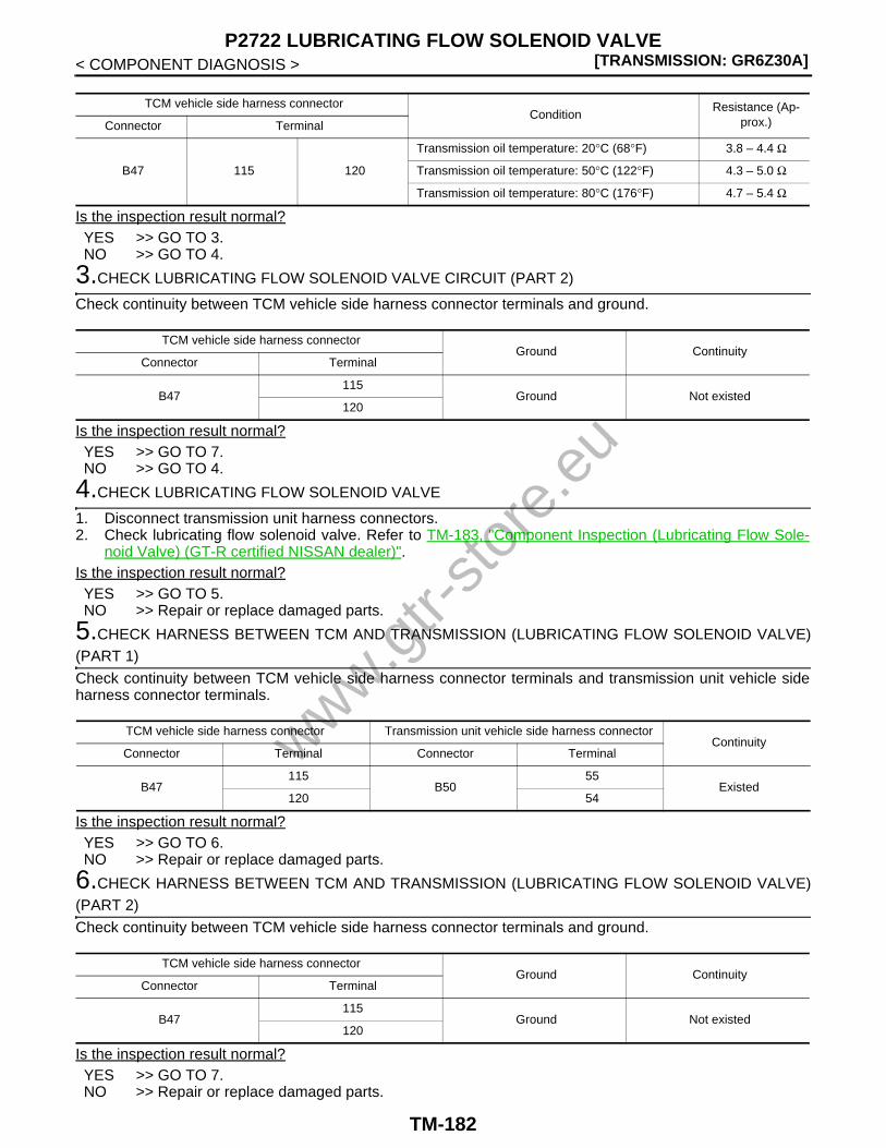
[TRANSMISSION: GR6Z30A]P2722 LUBRICATING FLOW SOLENOID VALVE
< COMPONENT DIAGNOSIS >
Is the inspection result normal?YES >> GO TO 3.NO >> GO TO 4.
3.CHECK LUBRICATING FLOW SOLENOID VALVE CIRCUIT (PART 2)
Check continuity between TCM vehicle side harness connector terminals and ground.
Is the inspection result normal?YES >> GO TO 7.NO >> GO TO 4.
4.CHECK LUBRICATING FLOW SOLENOID VALVE
1. Disconnect transmission unit harness connectors.2. Check lubricating flow solenoid valve. Refer to TM-183, "Component Inspection (Lubricating Flow Sole-
noid Valve) (GT-R certified NISSAN dealer)".Is the inspection result normal?YES >> GO TO 5.NO >> Repair or replace damaged parts.
5.CHECK HARNESS BETWEEN TCM AND TRANSMISSION (LUBRICATING FLOW SOLENOID VALVE)(PART 1)
Check continuity between TCM vehicle side harness connector terminals and transmission unit vehicle sideharness connector terminals.
Is the inspection result normal?YES >> GO TO 6.NO >> Repair or replace damaged parts.
6.CHECK HARNESS BETWEEN TCM AND TRANSMISSION (LUBRICATING FLOW SOLENOID VALVE)(PART 2)
Check continuity between TCM vehicle side harness connector terminals and ground.
Is the inspection result normal?YES >> GO TO 7.NO >> Repair or replace damaged parts.
TCM vehicle side harness connectorCondition
Resistance (Ap-prox.)Connector Terminal
B47 115 120
Transmission oil temperature: 20°C (68°F) 3.8 – 4.4 Ω
Transmission oil temperature: 50°C (122°F) 4.3 – 5.0 Ω
Transmission oil temperature: 80°C (176°F) 4.7 – 5.4 Ω
TCM vehicle side harness connectorGround Continuity
Connector Terminal
B47115
Ground Not existed120
TCM vehicle side harness connector Transmission unit vehicle side harness connectorContinuity
Connector Terminal Connector Terminal
B47115
B5055
Existed120 54
TCM vehicle side harness connectorGround Continuity
Connector Terminal
B47115
Ground Not existed120
www.gtr-
store
.eu
TM-182
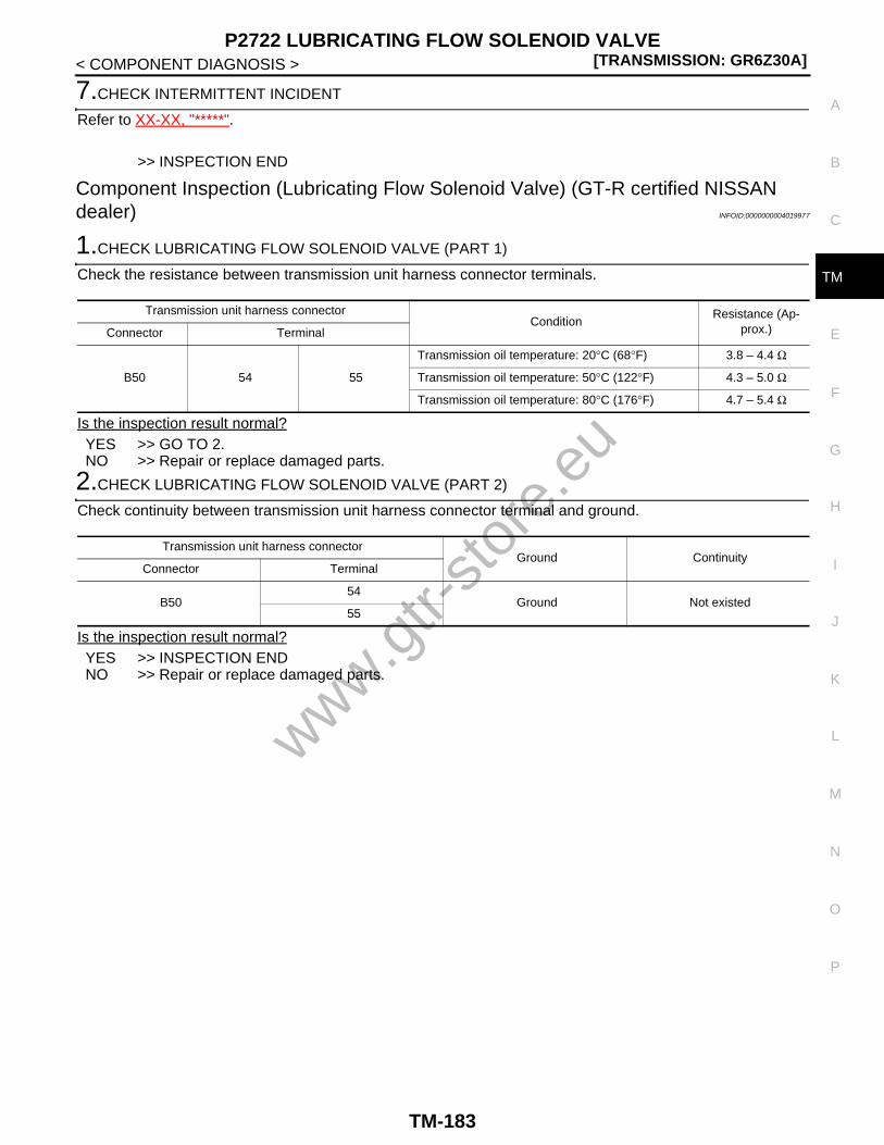
P2722 LUBRICATING FLOW SOLENOID VALVE[TRANSMISSION: GR6Z30A]
C
E
F
G
H
I
J
K
L
M
A
B
M
N
O
P
< COMPONENT DIAGNOSIS >
T
7.CHECK INTERMITTENT INCIDENT
Refer to XX-XX, "*****".
>> INSPECTION END
Component Inspection (Lubricating Flow Solenoid Valve) (GT-R certified NISSAN dealer) INFOID:0000000004019977
1.CHECK LUBRICATING FLOW SOLENOID VALVE (PART 1)
Check the resistance between transmission unit harness connector terminals.
Is the inspection result normal?YES >> GO TO 2.NO >> Repair or replace damaged parts.
2.CHECK LUBRICATING FLOW SOLENOID VALVE (PART 2)
Check continuity between transmission unit harness connector terminal and ground.
Is the inspection result normal?YES >> INSPECTION ENDNO >> Repair or replace damaged parts.
Transmission unit harness connectorCondition
Resistance (Ap-prox.)Connector Terminal
B50 54 55
Transmission oil temperature: 20°C (68°F) 3.8 – 4.4 Ω
Transmission oil temperature: 50°C (122°F) 4.3 – 5.0 Ω
Transmission oil temperature: 80°C (176°F) 4.7 – 5.4 Ω
Transmission unit harness connectorGround Continuity
Connector Terminal
B5054
Ground Not existed55
www.gtr-
store
.eu
TM-183

[TRANSMISSION: GR6Z30A]P2731 LINE PRESSURE SOLENOID VALVE
< COMPONENT DIAGNOSIS >
P2731 LINE PRESSURE SOLENOID VALVE
Description (GT-R certified NISSAN dealer) INFOID:0000000004019978
• The line pressure solenoid valve is installed on the front control module and controls the line pressure basedon the signal from TCM. This subsequently controls the lubricating flow.
• The line pressure solenoid valve is a N/H type (normal high) in which control oil pressure is built up when nocurrent flows through the coil.
DTC Logic (GT-R certified NISSAN dealer) INFOID:0000000004019979
DTC DETECTION LOGICNOTE:If DTC P0700 is displayed, perform the diagnosis of DTC P0700 first. Refer to TM-58, "DTC Logic (GT-R cer-tified NISSAN dealer)".
DTC CONFIRMATION PROCEDURECAUTION:Be careful of the driving speed.
1.PREPARATION BEFORE OPERATION (PART 1)
If another “DTC CONFIRMATION PROCEDURE” is performed just before the next test, turn the ignitionswitch OFF and wait for 10 seconds or more, then perform the next test.
>> GO TO 2.
2.PREPARATION BEFORE OPERATION (PART 2)
With CONSULT-III1. Turn the ignition switch ON.2. Select “FLUID TEMP” in “Data Monitor”.
Without CONSULT-III1. Turn the ignition switch ON.2. Check “TRANS OIL TEMP” on multi-function display.Is the oil temperature 30°C (86°F) or more?YES >> GO TO 3.NO >> Warm up the transmission.
3.PERFORM DTC CONFIRMATION PROCEDURE
With CONSULT-III1. Shift the shift lever to the N position.
CAUTION:No shift position indicator in the combination meter blinks.
2. Start the engine.3. With the shift lever in the N position, and run at idle for 5 seconds or more.4. Check “Self Diagnostic Result” of “TRANSMISSION”.
Without CONSULT-III1. Shift the shift lever to the N position.
CAUTION:No shift position indicator in the combination meter blinks.
2. Start the engine.3. With the shift lever in the N position, and run at idle for 5 seconds or more.4. Check self-diagnosis.Is DTC P2731 detected?
DTC Self-diagnosis name DTC detection condition Possible causes
P2731Line pressure solenoid valve system current
A DTC is set if the line pressure solenoid valve monitor current value is less than 0.2 A when the line pressure solenoid valve target current value is more than 0.38 A.
• Line pressure solenoid valve• Harness or connector
(Open or short in the line pressure sole-noid valve circuit)
www.gtr-
store
.eu
TM-184

P2731 LINE PRESSURE SOLENOID VALVE[TRANSMISSION: GR6Z30A]
C
E
F
G
H
I
J
K
L
M
A
B
M
N
O
P
< COMPONENT DIAGNOSIS >
T
YES >> Go to TM-185, "Diagnosis Procedure (GT-R certified NISSAN dealer)".NO >> INSPECTION END
Diagnosis Procedure (GT-R certified NISSAN dealer) INFOID:0000000004019980
1.CHECK GROUND CONNECTION
1. Turn ignition switch OFF.2. Check ground connections B31 and ground cable connections. Refer to “Ground Inspection” in XX-XX,
"*****".Is the inspection result normal?YES >> GO TO 2.NO >> Repair or replace damaged parts.
2.CHECK LINE PRESSURE SOLENOID VALVE CIRCUIT (PART 1)
1. Disconnect TCM harness connectors.2. Check resistance between TCM vehicle side harness connector terminals.
Is the inspection result normal?YES >> GO TO 3.NO >> GO TO 4.
3.CHECK LINE PRESSURE SOLENOID VALVE CIRCUIT (PART 2)
Check continuity between TCM vehicle side harness connector terminals and ground.
Is the inspection result normal?YES >> GO TO 7.NO >> GO TO 4.
4.CHECK LINE PRESSURE SOLENOID VALVE
1. Disconnect transmission unit harness connectors.2. Check line pressure solenoid valve. Refer to TM-186, "Component Inspection (Line Pressure Solenoid
Valve) (GT-R certified NISSAN dealer)".Is the inspection result normal?YES >> GO TO 5.NO >> Repair or replace damaged parts.
5.CHECK HARNESS BETWEEN TCM AND TRANSMISSION (LINE PRESSURE SOLENOID VALVE) (PART1)
Check continuity between TCM vehicle side harness connector terminals and transmission unit vehicle sideharness connector terminals.
TCM vehicle side harness connectorCondition
Resistance (Ap-prox.)Connector Terminal
B47 113 118
Transmission oil temperature: 20°C (68°F) 3.8 – 4.4 Ω
Transmission oil temperature: 50°C (122°F) 4.3 – 5.0 Ω
Transmission oil temperature: 80°C (176°F) 4.7 – 5.4 Ω
TCM vehicle side harness connectorGround Continuity
Connector Terminal
B47113
Ground Not existed118
TCM vehicle side harness connector Transmission unit vehicle side harness connectorContinuity
Connector Terminal Connector Terminal
B47113
B5049
Existed118 48
www.gtr-
store
.eu
TM-185

[TRANSMISSION: GR6Z30A]P2731 LINE PRESSURE SOLENOID VALVE
< COMPONENT DIAGNOSIS >Is the inspection result normal?YES >> GO TO 6.NO >> Repair or replace damaged parts.
6.CHECK HARNESS BETWEEN TCM AND TRANSMISSION (LINE PRESSURE SOLENOID VALVE) (PART2)
Check continuity between TCM vehicle side harness connector terminals and ground.
Is the inspection result normal?YES >> GO TO 7.NO >> Repair or replace damaged parts.
7.CHECK INTERMITTENT INCIDENT
Refer to XX-XX, "*****".
>> INSPECTION END
Component Inspection (Line Pressure Solenoid Valve) (GT-R certified NISSAN dealer)INFOID:0000000004019981
1.CHECK LINE PRESSURE SOLENOID VALVE (PART 1)
Check the resistance between transmission unit harness connector terminals.
Is the inspection result normal?YES >> GO TO 2.NO >> Repair or replace damaged parts.
2.CHECK LINE PRESSURE SOLENOID VALVE (PART 2)
Check continuity between transmission unit harness connector terminal and ground.
Is the inspection result normal?YES >> INSPECTION ENDNO >> Repair or replace damaged parts.
TCM vehicle side harness connectorGround Continuity
Connector Terminal
B47113
Ground Not existed118
Transmission unit harness connectorCondition
Resistance (Ap-prox.)Connector Terminal
B50 48 49
Transmission oil temperature: 20°C (68°F) 3.8 – 4.4 Ω
Transmission oil temperature: 50°C (122°F) 4.3 – 5.0 Ω
Transmission oil temperature: 80°C (176°F) 4.7 – 5.4 Ω
Transmission unit harness connectorGround Continuity
Connector Terminal
B5048
Ground Not existed49
www.gtr-
store
.eu
TM-186

P2765 CLUTCH B SPEED SENSOR[TRANSMISSION: GR6Z30A]
C
E
F
G
H
I
J
K
L
M
A
B
M
N
O
P
< COMPONENT DIAGNOSIS >
T
P2765 CLUTCH B SPEED SENSOR
Description (GT-R certified NISSAN dealer) INFOID:0000000004019982
• The clutch B speed sensor detects the 1st counter gear speed. The clutch B speed sensor converts the 1stcounter gear speed into pulse signal and transmits the signal to TCM.
• TCM calculates the clutch B (a clutch for odd number gears and reverse) speed based on the signal from theclutch B speed sensor.
DTC Logic (GT-R certified NISSAN dealer) INFOID:0000000004019983
DTC DETECTION LOGIC
DTC CONFIRMATION PROCEDURECAUTION:Be careful of the driving speed.
1.PREPARATION BEFORE OPERATION
If another “DTC CONFIRMATION PROCEDURE” is performed just before the next test, turn the ignitionswitch OFF and wait for 10 seconds or more, then perform the next test.
>> GO TO 2.
2.PERFORM DTC CONFIRMATION PROCEDURE
With CONSULT-III1. Start the engine.2. Select “RANGE”, “GEAR” and “ENGINE SPEED” in “Data Monitor”.3. Run the vehicle and maintain the following conditions for 5 seconds or more.
4. Check “Self Diagnostic Result” of “TRANSMISSION”.Without CONSULT-III
1. Start the engine.2. Run the vehicle and maintain the following conditions for 5 seconds or more.
3. Check self-diagnosis.Is DTC P2765 detected?YES >> Go to TM-188, "Diagnosis Procedure (GT-R certified NISSAN dealer)".NO >> INSPECTION END
DTC Self-diagnosis name DTC detection condition Possible cause
P2765Clutch B speed pulse signal compatibility
A DTC is set if the status 1 or 2 below is de-tected with the sleeve B1 or B2 engaged in an odd number gear.1. The difference between the actual out-
put shaft speed and the output shaft speed converted from the clutch B speed is 1,000 rpm or more.
2. The difference between the vehicle speed signal (meter) (CAN signal) and the output shaft speed converted from the clutch B speed is 1,000 rpm or more.
• Clutch B speed sensor• Harness or connector
(Open or short in the clutch B speed sen-sor circuit)
RANGE : M
GEAR : 3
ENGINE SPEED : 2,000 rpm or more
Shift lever : M range
Gear : 3
Engine speed : 2,000 rpm or more
www.gtr-
store
.eu
TM-187

[TRANSMISSION: GR6Z30A]P2765 CLUTCH B SPEED SENSOR
< COMPONENT DIAGNOSIS >
Diagnosis Procedure (GT-R certified NISSAN dealer) INFOID:0000000004019984
1.CHECK GROUND CONNECTION
1. Turn ignition switch OFF.2. Check ground connections B31 and ground cable connections. Refer to “Ground Inspection” in XX-XX,
"*****".Is the inspection result normal?YES >> GO TO 2.NO >> Repair or replace damaged parts.
2.CHECK TCM OUTPUT SIGNAL CIRCUIT
Check voltage between TCM vehicle side harness connector terminals.
Is the inspection result normal?YES >> GO TO 3.NO >> Go to TM-194, "Diagnosis Procedure (GT-R certified NISSAN dealer)".
3.CHECK TCM INPUT SIGNAL CIRCUIT
1. Start engine.2. Check voltage between TCM vehicle side harness connector terminals.
Is the inspection result normal?YES >> GO TO 4.NO >> GO TO 5.
4.CHECK INTERMITTENT INCIDENT
Refer to XX-XX, "*****".
>> INSPECTION END
5.CHECK HARNESS BETWEEN TCM AND TRANSMISSION (CLUTCH B SPEED SENSOR) (PART 1)
Check continuity between TCM vehicle side harness connector terminals and transmission unit vehicle sideharness connector terminals.
Is the inspection result normal?
TCM vehicle side harness connectorCondition Voltage (Approx.)
Connector Terminal Terminal
B46 78 4Ignition switch ON 5 V
Ignition switch OFF 0 V
TCM vehicle side harness connectorCondition Voltage (Approx.)
Connector Terminal
B46 82 4• M range, 1st gear• Engine speed: 2,000 rpm
NNDIA0062ZZ
TCM vehicle side harness connector Transmission unit vehicle side harness connectorContinuity
Connector Terminal Connector Terminal
B46
78
B49
36
Existed82 33
86 26
www.gtr-
store
.eu
TM-188

P2765 CLUTCH B SPEED SENSOR[TRANSMISSION: GR6Z30A]
C
E
F
G
H
I
J
K
L
M
A
B
M
N
O
P
< COMPONENT DIAGNOSIS >
T
YES >> GO TO 6.NO >> Repair or replace damaged parts.
6.CHECK HARNESS BETWEEN TCM AND TRANSMISSION (CLUTCH B SPEED SENSOR) (PART 2)
Check continuity between TCM vehicle side harness connector terminals and ground.
Is the inspection result normal?YES >> GO TO 7.NO >> Repair or replace damaged parts.
7.CHECK INTERMITTENT INCIDENT
Refer to XX-XX, "*****".Is the inspection result normal?YES >> Replace transmission assembly. Refer to TM-291, "Exploded View (GT-R certified NISSAN
dealer)".NO >> Repair or replace damaged parts.
TCM vehicle side harness connectorGround Continuity
Connector Terminal
B46
78
Ground Not existed82
86
www.gtr-
store
.eu
TM-189

[TRANSMISSION: GR6Z30A]P2776 PADDLE SHIFTER (SHIFT-UP SWITCH)
< COMPONENT DIAGNOSIS >
P2776 PADDLE SHIFTER (SHIFT-UP SWITCH)
Description (GT-R certified NISSAN dealer) INFOID:0000000004019985
The paddle shifter (shift-up switch) is installed on the steering column and commands TCM the transition to Mrange and upshift according to a driver's request.
DTC Logic (GT-R certified NISSAN dealer) INFOID:0000000004019986
DTC DETECTION LOGICNOTE:• If DTC P0700 is detected, first diagnose the DTC P0700. Refer to TM-58, "DTC Logic (GT-R certified NIS-
SAN dealer)".• If DTC P0705 is detected, first diagnose the DTC P0705. Refer to TM-62, "DTC Logic (GT-R certified NIS-
SAN dealer)".
DTC CONFIRMATION PROCEDURE
1.PREPARATION BEFORE OPERATION
If another “DTC CONFIRMATION PROCEDURE” is performed just before the next test, turn the ignitionswitch OFF and wait for 10 seconds or more, then perform the next test.
>> GO TO 2.
2.PERFORM DTC CONFIRMATION PROCEDURE
With CONSULT-III1. Start the engine and wait for 1 minute or more.2. Check “Self Diagnostic Result” of “TRANSMISSION”.Is DTC P2776 detected?YES >> Go to TM-190, "Diagnosis Procedure (GT-R certified NISSAN dealer)".NO >> INSPECTION END
Diagnosis Procedure (GT-R certified NISSAN dealer) INFOID:0000000004019987
1.CHECK GROUND CONNECTION
1. Turn ignition switch OFF.2. Check ground connections B31, M11 and M55. Refer to “Ground Inspection” in XX-XX, "*****".Is the inspection result normal?YES >> GO TO 2.NO >> Repair or replace damaged parts.
2.CHECK PADDLE SHIFTER (SHIFT-UP SWITCH)
1. Disconnect paddle shifter (shift-up switch) harness connector.2. Check paddle shifter (shift-up switch). Refer to TM-191, "Component Inspection [Paddle Shifter (Shift-up
Switch)] (GT-R certified NISSAN dealer)".Is the inspection result normal?YES >> GO TO 3.NO >> Repair or replace damaged parts.
3.CHECK HARNESS BETWEEN TCM AND PADDLE SHIFTER (SHIFT-UP SWITCH)
1. Disconnect TCM harness connectors.2. Check continuity between TCM vehicle side harness connector terminal and ground.
DTC Self-diagnosis name DTC detection condition Possible cause
P2776Continuation of shift-up switch ON
A DTC is set if TCM detects the paddle shifter (shift-up switch) ON signal for a cer-tain period of time.
• Paddle shifter (shift-up switch)• Harness or connector
[Short in the paddle shifter (shift-up switch) circuit]
www.gtr-
store
.eu
TM-190

P2776 PADDLE SHIFTER (SHIFT-UP SWITCH)[TRANSMISSION: GR6Z30A]
C
E
F
G
H
I
J
K
L
M
A
B
M
N
O
P
< COMPONENT DIAGNOSIS >
T
Is the inspection result normal?YES >> GO TO 4.NO >> Repair or replace damaged parts.
4.CHECK HARNESS BETWEEN PADDLE SHIFTER (SHIFT-UP SWITCH) AND GROUND
Check continuity between paddle shifter (shift-up switch) vehicle side harness connector terminal and ground.
Is the inspection result normal?YES >> GO TO 5.NO >> Repair or replace damaged parts.
5.CHECK INTERMITTENT INCIDENT
Refer to XX-XX, "*****".
>> INSPECTION END
Component Inspection [Paddle Shifter (Shift-up Switch)] (GT-R certified NISSAN deal-er) INFOID:0000000004019988
1.CHECK PADDLE SHIFTER (SHIFT-UP SWITCH)
Check continuity between paddle shifter (shift-up switch) connector terminals.
Is the inspection result normal?YES >> INSPECTION ENDNO >> Repair or replace damaged parts.
TCM vehicle side harness connectorGround Continuity
Connector Terminal
B45 39 Ground Not existed
Paddle shifter (shift-up switch) vehicle side harness connectorGround Continuity
Connector Terminal
M39 1 Ground Existed
Paddle shifter (shift-up switch) connectorCondition Continuity
Connector Terminal
M39 1 3The paddle shifter (shift-up switch) is pulled Existed
Other than the above Not existed
www.gtr-
store
.eu
TM-191

[TRANSMISSION: GR6Z30A]P2780 PADDLE SHIFTER (SHIFT-DOWN SWITCH)
< COMPONENT DIAGNOSIS >
P2780 PADDLE SHIFTER (SHIFT-DOWN SWITCH)
Description (GT-R certified NISSAN dealer) INFOID:0000000004019989
The paddle shifter (shift-down switch) is installed on the steering column and commands TCM the transition toM range and downshift according to a driver's request.
DTC Logic (GT-R certified NISSAN dealer) INFOID:0000000004019990
DTC DETECTION LOGICNOTE:• If DTC P0700 is detected, first diagnose the DTC P0700. Refer to TM-58, "DTC Logic (GT-R certified NIS-
SAN dealer)".• If DTC P0705 is detected, first diagnose the DTC P0705. Refer to TM-62, "DTC Logic (GT-R certified NIS-
SAN dealer)".
DTC CONFIRMATION PROCEDURE
1.PREPARATION BEFORE OPERATION
If another “DTC CONFIRMATION PROCEDURE” is performed just before the next test, turn the ignitionswitch OFF and wait for 10 seconds or more, then perform the next test.
>> GO TO 2.
2.PERFORM DTC CONFIRMATION PROCEDURE
With CONSULT-III1. Start the engine and wait for 1 minute or more.2. Check “Self Diagnostic Result” of “TRANSMISSION”.Is DTC P2780 detected?YES >> Go to TM-192, "Diagnosis Procedure (GT-R certified NISSAN dealer)".NO >> INSPECTION END
Diagnosis Procedure (GT-R certified NISSAN dealer) INFOID:0000000004019991
1.CHECK GROUND CONNECTION
1. Turn ignition switch OFF.2. Check ground connections B31, M11 and M55. Refer to “Ground Inspection” in XX-XX, "*****".Is the inspection result normal?YES >> GO TO 2.NO >> Repair or replace damaged parts.
2.CHECK PADDLE SHIFTER (SHIFT-DOWN SWITCH)
1. Disconnect paddle shifter (shift-down switch) harness connector.2. Check paddle shifter (shift-down switch). Refer to TM-193, "Component Inspection [Paddle Shifter (Shift-
down Switch)] (GT-R certified NISSAN dealer)".Is the inspection result normal?YES >> GO TO 3.NO >> Repair or replace damaged parts.
3.CHECK HARNESS BETWEEN TCM AND PADDLE SHIFTER (SHIFT-DOWN SWITCH)
1. Disconnect TCM harness connectors.2. Check continuity between TCM vehicle side harness connector terminal and ground.
DTC Self-diagnosis name DTC detection condition Possible cause
P2780Continuation of shift-down switch ON
A DTC is set if TCM detects the paddle shifter (shift-down switch) ON signal for a certain period.
• Paddle shifter (shift-down switch)• Harness or connector
[Short in the paddle shifter (shift-down switch) circuit]
www.gtr-
store
.eu
TM-192
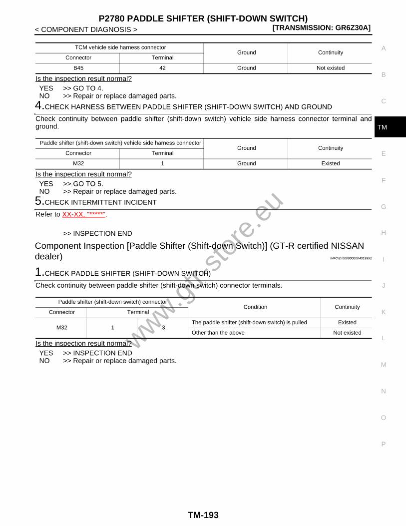
P2780 PADDLE SHIFTER (SHIFT-DOWN SWITCH)[TRANSMISSION: GR6Z30A]
C
E
F
G
H
I
J
K
L
M
A
B
M
N
O
P
< COMPONENT DIAGNOSIS >
T
Is the inspection result normal?YES >> GO TO 4.NO >> Repair or replace damaged parts.
4.CHECK HARNESS BETWEEN PADDLE SHIFTER (SHIFT-DOWN SWITCH) AND GROUND
Check continuity between paddle shifter (shift-down switch) vehicle side harness connector terminal andground.
Is the inspection result normal?YES >> GO TO 5.NO >> Repair or replace damaged parts.
5.CHECK INTERMITTENT INCIDENT
Refer to XX-XX, "*****".
>> INSPECTION END
Component Inspection [Paddle Shifter (Shift-down Switch)] (GT-R certified NISSAN dealer) INFOID:0000000004019992
1.CHECK PADDLE SHIFTER (SHIFT-DOWN SWITCH)
Check continuity between paddle shifter (shift-down switch) connector terminals.
Is the inspection result normal?YES >> INSPECTION ENDNO >> Repair or replace damaged parts.
TCM vehicle side harness connectorGround Continuity
Connector Terminal
B45 42 Ground Not existed
Paddle shifter (shift-down switch) vehicle side harness connectorGround Continuity
Connector Terminal
M32 1 Ground Existed
Paddle shifter (shift-down switch) connectorCondition Continuity
Connector Terminal
M32 1 3The paddle shifter (shift-down switch) is pulled Existed
Other than the above Not existed
www.gtr-
store
.eu
TM-193

[TRANSMISSION: GR6Z30A]MAIN POWER SUPPLY
< COMPONENT DIAGNOSIS >
MAIN POWER SUPPLY
Description (GT-R certified NISSAN dealer) INFOID:0000000004019993
Supply power to TCM.
Diagnosis Procedure (GT-R certified NISSAN dealer) INFOID:0000000004019994
1.CHECK GROUND CONNECTION
1. Turn ignition switch OFF.2. Check ground connection B31. Refer to “Ground Inspection” in XX-XX, "*****".Is the inspection result normal?YES >> GO TO 2.NO >> Repair or replace damaged parts.
2.CHECK HARNESS BETWEEN TCM AND GROUND
1. Disconnect TCM harness connectors.2. Check continuity between TCM vehicle side harness connector terminal and ground.
Is the inspection result normal?YES >> GO TO 3.NO >> Repair or replace damaged parts.
3.CHECK TCM INPUT SIGNAL CIRCUIT (PART 1)
Check voltage between TCM vehicle side harness connector terminals.
Is the inspection result normal?YES >> GO TO 7.NO >> GO TO 4.
4.CHECK HARNESS BETWEEN TCM AND FUSE BLOCK (J/B) (PART 1)
1. Disconnect fuse block (J/B) harness connector.2. Check continuity between TCM vehicle side harness connector terminal and fuse block (J/B) vehicle side
harness connector terminal.
Is the inspection result normal?YES >> GO TO 5.NO >> Repair or replace damaged parts.
5.CHECK HARNESS BETWEEN TCM AND FUSE BLOCK (J/B) (PART 2)
Check continuity between TCM vehicle side harness connector terminal and ground.
TCM vehicle side harness connectorGround Continuity
Connector Terminal
B45
3
Ground Existed4
7
8
TCM vehicle side harness connectorCondition Voltage (Approx.)
Connector Terminal
B45 9 4 AlwaysBattery voltage
(11 – 14 V)
TCM vehicle side harness connector Fuse block (J/B) vehicle side harness connectorContinuity
Connector Terminal Connector Terminal
B45 9 M1 4A Existed
www.gtr-
store
.eu
TM-194

MAIN POWER SUPPLY[TRANSMISSION: GR6Z30A]
C
E
F
G
H
I
J
K
L
M
A
B
M
N
O
P
< COMPONENT DIAGNOSIS >
T
Is the inspection result normal?YES >> GO TO 6.NO >> Repair or replace damaged parts.
6.DETECT MALFUNCTIONING ITEM (PART 1)
Check the following. Refer to XX-XX, "*****".• 10A fuse [No. 9, located in the fuse block (J/B)]• Fuse block (J/B)• Harness for open or short between battery and fuse blockIs the inspection result normal?YES >> GO TO 7.NO >> Repair or replace damaged parts.
7.CHECK TCM INPUT SIGNAL CIRCUIT (PART 2)
Check voltage between TCM vehicle side harness connector terminals.
Is the inspection result normal?YES >> GO TO 11.NO >> GO TO 8.
8.CHECK HARNESS BETWEEN TCM AND IPDM E/R (INTELLIGENT POWER DISTRIBUTION MODULEENGINE ROOM) (PART 1)
1. Disconnect IPDM E/R harness connector.2. Check continuity between TCM vehicle side harness connector terminal and IPDM E/R (intelligent power
distribution module engine room) vehicle side harness connector terminal.
Is the inspection result normal?YES >> GO TO 9.NO >> Repair or replace damaged parts.
9.CHECK HARNESS BETWEEN TCM AND IPDM E/R (INTELLIGENT POWER DISTRIBUTION MODULEENGINE ROOM) (PART 2)
Check continuity between TCM vehicle side harness connector terminal and ground.
Is the inspection result normal?YES >> GO TO 10.NO >> Repair or replace damaged parts.
10.DETECT MALFUNCTIONING ITEM (PART 2)
TCM vehicle side harness connectorGround Continuity
Connector Terminal
B45 9 Ground Not existed
TCM vehicle side harness connectorCondition Voltage (Approx.)
Connector Terminal
B45 17 4Ignition switch ON
Battery voltage (11 – 14 V)
Ignition switch OFF 0 V
TCM vehicle side harness connectorIPDM E/R (intelligent power distribution module en-
gine room) vehicle side harness connector Continuity
Connector Terminal Connector Terminal
B45 17 E7 58 Existed
TCM vehicle side harness connectorGround Continuity
Connector Terminal
B45 17 Ground Not existed
www.gtr-
store
.eu
TM-195

[TRANSMISSION: GR6Z30A]MAIN POWER SUPPLY
< COMPONENT DIAGNOSIS >Check the following. Refer to XX-XX, "*****".• 10A fuse [No. 43, located in the IPDM E/R (intelligent power distribution module engine room)]• IPDM E/R• Harness for open or short between push-button ignition switch and IPDM E/R (intelligent power distribution
module engine room)• Push-button ignition switchIs the inspection result normal?YES >> GO TO 11.NO >> Repair or replace damaged parts.
11.CHECK INTERMITTENT INCIDENT
Refer to XX-XX, "*****".
>> INSPECTION END
www.gtr-
store
.eu
TM-196

SET-UP SWITCH (TRANSMISSION)[TRANSMISSION: GR6Z30A]
C
E
F
G
H
I
J
K
L
M
A
B
M
N
O
P
< COMPONENT DIAGNOSIS >
T
SET-UP SWITCH (TRANSMISSION)
Description (GT-R certified NISSAN dealer) INFOID:0000000004019995
If R or SNOW on the set-up switch (transmission) is selected, TCM energizes the circuit for each mode andilluminates the lamp.
Diagnosis Procedure (GT-R certified NISSAN dealer) INFOID:0000000004019996
1.CHECK GROUND CONNECTION
1. Turn ignition switch OFF.2. Check ground connection B31. Refer to “Ground Inspection” in XX-XX, "*****".Is the inspection result normal?YES >> GO TO 2.NO >> Repair or replace damaged parts.
2.CHECK POWER SUPPLY CIRCUIT
1. Disconnect set-up switch harness connector.2. Turn ignition switch ON.3. Check voltage between set-up switch vehicle side harness connector and ground.
Is the inspection result normal?YES >> GO TO 3.NO >> GO TO 5.
3.CHECK HARNESS BETWEEN TCM AND SET-UP SWITCH (PART 1)
1. Turn ignition switch OFF.2. Disconnect TCM harness connector.3. Check continuity between TCM vehicle side harness connector terminals and set-up switch vehicle side
harness connector terminals.
Is the inspection result normal?YES >> GO TO 4.NO >> Repair or replace the malfunctioning parts.
4.CHECK HARNESS BETWEEN TCM AND SET-UP SWITCH (PART 2)
Check continuity between TCM vehicle side harness connector terminal and ground.
Is the inspection result normal?YES >> GO TO 8.NO >> Repair or replace damaged parts.
Set-up switch vehicle side harness connector Ground Condition Voltage (Approx.)
Connector Terminal
M73 18 GroundIgnition switch ON
Battery voltage (11 – 14 V)
Ignition switch OFF 0 V
TCM vehicle side harness connector Set-up switch vehicle side harness connectorContinuity
Connector Terminal Connector Terminal
B4545
M7316
Existed47 10
TCM vehicle side harness connectorGround Continuity
Connector Terminal
B4545
Ground Not existed47
www.gtr-
store
.eu
TM-197

[TRANSMISSION: GR6Z30A]SET-UP SWITCH (TRANSMISSION)
< COMPONENT DIAGNOSIS >
5.CHECK HARNESS BETWEEN SET-UP SWITCH AND IPDM E/R (INTELLIGENT POWER DISTRIBUTIONMODULE ENGINE ROOM) (PART 1)
1. Turn ignition switch OFF.2. Disconnect IPDM E/R harness connector.3. Check continuity between set-up switch vehicle side harness connector terminal and IPDM E/R (intelli-
gent power distribution module engine room) vehicle side harness connector terminal.
Is the inspection result normal?YES >> GO TO 6.NO >> Repair or replace the malfunctioning parts.
6.CHECK HARNESS BETWEEN SET-UP SWITCH AND IPDM E/R (INTELLIGENT POWER DISTRIBUTIONMODULE ENGINE ROOM) (PART 2)
Check continuity between set-up switch vehicle side harness connector terminal and ground.
Is the inspection result normal?YES >> GO TO 7.NO >> Repair or replace damaged parts.
7.DETECT MALFUNCTIONING ITEM
Check the following. Refer to XX-XX, "*****".• 10A fuse [No.45, located in the IPDM E/R (intelligent power distribution module engine room)]• IPDM E/R (intelligent power distribution module engine room)• Harness for open or short between push-button ignition switch and IPDM E/R (intelligent power distribution
module engine room)• Push-button ignition switchIs the inspection result normal?YES >> GO TO 8.NO >> Repair or replace damaged parts.
8.CHECK INTERMITTENT INCIDENT
Refer to XX-XX, "*****".
>> INSPECTION END
Set-up switch vehicle side harness connectorIPDM E/R (intelligent power distribution module en-
gine room) vehicle side harness connector Continuity
Connector Terminal Connector Terminal
M73 18 E5 25 Existed
Set-up switch vehicle side harness connectorGround Continuity
Connector Terminal
M73 18 Ground Not existed
www.gtr-
store
.eu
TM-198

SHIFT POSITION INDICATOR CIRCUIT[TRANSMISSION: GR6Z30A]
C
E
F
G
H
I
J
K
L
M
A
B
M
N
O
P
< COMPONENT DIAGNOSIS >
T
SHIFT POSITION INDICATOR CIRCUIT
Description (GT-R certified NISSAN dealer) INFOID:0000000004019997
• TCM transmits the position indicator signals to the combination meter via CAN communication.• The A range indicator and M range indicator are included in the shift position indicator.
Diagnosis Procedure (GT-R certified NISSAN dealer) INFOID:0000000004019998
1.CHECK DTC WITH TRANSMISSION
With CONSULT-III1. Turn ignition switch ON.2. Check “Self Diagnostic Result” of “TRANSMISSION”.Is the inspection result normal?YES >> GO TO 2.NO >> Check DTC detected item. Refer to TM-233, "DTC Index".
2.DETECT MALFUNCTIONING ITEM
Check the following harness connector pin terminals for any malfunctions on the connections, harness sheathor other areas. Refer to XX-XX, "*****"• Control device harness connector• Paddle shifter (shift-up switch) harness connector• Paddle shifter (shift-down switch) harness connector• TCM harness connector• Transmission harness connector• Park position switch harness connector• Combination meter harness connectorIs the inspection result normal?YES >> Replace the combination meter. Refer to XX-XX, "*****".NO >> Repair or replace damaged parts.
www.gtr-
store
.eu
TM-199

[TRANSMISSION: GR6Z30A]SHIFT LOCK SYSTEM
< COMPONENT DIAGNOSIS >
SHIFT LOCK SYSTEM
Description (GT-R certified NISSAN dealer) INFOID:0000000004019999
The shift lock system mainly consists of the following components.
Component Function Check (GT-R certified NISSAN dealer) INFOID:0000000004020000
1.CHECK INFORMATION DISPLAY INDICATIONS
1. Turn the ignition switch ON.2. Check the information display indications in the combination meter.Does the “T/M SYSTEM CHECK IN PROCESS” indication disappear?YES >> GO TO 2.NO >> Check “Self Diagnostic Result” of “TRANSMISSION”.
2.CHECK SHIFT LOCK OPERATION (PART 1)
1. Shift the shift lever to the P position.2. Shift the shift lever to any other position with the brake pedal released.Can the shift lever be shifted to other positions?YES >> Go to TM-200, "Diagnosis Procedure (GT-R certified NISSAN dealer)".NO >> GO TO 3.
3.CHECK SHIFT LOCK OPERATION (PART 2)
Shift the shift lever to any other position with the brake pedal depressed.Can the shift lever be shifted to other positions?YES >> INSPECTION ENDNO >> Go to TM-200, "Diagnosis Procedure (GT-R certified NISSAN dealer)".
Diagnosis Procedure (GT-R certified NISSAN dealer) INFOID:0000000004020001
1.CHECK SHIFT POSITION
Check the shift positions. Refer to “Inspection” in TM-268, "Inspection and Adjustment".Is the inspection result normal?YES >> GO TO 2.NO >> Adjust the shift positions. Refer to “Adjustment” in TM-268, "Inspection and Adjustment".
2.CHECK GROUND CONNECTION
1. Turn ignition switch OFF.2. Check ground connections B31 and B14. Refer to “Ground Inspection” in XX-XX, "*****".Is the inspection result normal?YES >> GO TO 3.NO >> Repair or replace damaged parts.
3.CHECK POWER SUPPLY CIRCUIT (PART 1)
1. Disconnect the control device harness connector.2. Turn the ignition switch ON.3. Check voltage between the control device vehicle side harness connector and ground.
Component Function
Shift lock solenoid Activated by the ignition switch and stop lamp switch signals.
Stop lamp switchWhen the brake pedal is depressed, the stop lamp switch turns ON and the transistor is energized via TCM.
www.gtr-
store
.eu
TM-200

SHIFT LOCK SYSTEM[TRANSMISSION: GR6Z30A]
C
E
F
G
H
I
J
K
L
M
A
B
M
N
O
P
< COMPONENT DIAGNOSIS >
T
Is the inspection result normal?YES >> GO TO 4.NO >> GO TO 7.
4.CHECK TCM OUTPUT SIGNAL CIRCUIT
Check the voltage between the control device vehicle side harness connector and ground.
Is the inspection result normal?YES >> GO TO 5.NO >> GO TO 10.
5.CHECK HARNESS BETWEEN CONTROL DEVICE (SHIFT LOCK SOLENOID) AND GROUND
Check continuity between the control device vehicle side harness connector terminal and ground.
Is the inspection result normal?YES >> GO TO 6.NO >> Repair or replace damaged parts.
6.CHECK INTERMITTENT INCIDENT
Refer to XX-XX, "*****".Is the inspection result normal?YES >> Replace the control device. Refer to TM-272, "Exploded View".NO >> Repair or replace damaged parts.
7.CHECK HARNESS BETWEEN CONTROL DEVICE (SHIFT LOCK SOLENOID) AND FUSE BLOCK (J/B)(PART 1)
1. Turn the ignition switch OFF.2. Disconnect the fuse block (J/B) harness connector.3. Check the continuity between the control device vehicle side harness connector terminal and the fuse
block (J/B) vehicle side harness connector terminal.
Is the inspection result normal?YES >> GO TO 8.NO >> Repair or replace damaged parts.
8.CHECK HARNESS BETWEEN CONTROL DEVICE (SHIFT LOCK SOLENOID) AND FUSE BLOCK (J/B)
Control device vehicle side harness connector Ground Condition Voltage (Approx.)
Connector Terminal
B20 13 GroundIgnition switch ON
Battery voltage (11 – 14 V)
Ignition switch OFF 0 V
Control device vehicle side harness connector Ground Condition Voltage (Approx.)
Connector Terminal
B20 14 Ground
• Shift lever: P position• Brake pedal depressed
Battery voltage (11 – 14 V)
Other than the above 0 V
Control device vehicle side harness connectorGround Continuity
Connector Terminal
B20 18 Ground Existed
Control device vehicle side harness connector Fuse block (J/B) vehicle side harness connectorContinuity
Connector Terminal Connector Terminal
E20 13 M3 12C Existed
www.gtr-
store
.eu
TM-201

[TRANSMISSION: GR6Z30A]SHIFT LOCK SYSTEM
< COMPONENT DIAGNOSIS >(PART 2)
Check continuity between the control device vehicle side harness connector terminal and ground.
Is the inspection result normal?YES >> GO TO 9.NO >> Repair or replace damaged parts.
9.DETECT MALFUNCTIONING ITEM
Check the following. Refer to XX-XX, "*****".• 10A fuse [No.4, fuse block (J/B)]• Fuse block (J/B)• Harness for open or short between fuse block (J/B) and push-button ignition switch• Push-button ignition switchIs the inspection result normal?YES >> GO TO 19.NO >> Repair or replace damaged parts.
10.CHECK HARNESS BETWEEN TCM AMD CONTROL DEVICE (SHIFT LOCK SOLENOID) (PART 1)
1. Turn the ignition switch OFF.2. Disconnect the TCM harness connector.3. Check the continuity between the TCM vehicle side harness connector terminal and the control device
vehicle side harness connector terminal.
Is the inspection result normal?YES >> GO TO 11.NO >> Repair or replace damaged parts.
11.CHECK HARNESS BETWEEN TCM AMD CONTROL DEVICE (SHIFT LOCK SOLENOID) (PART 2)
Check the continuity between the TCM vehicle side harness connector terminal and ground.
Is the inspection result normal?YES >> GO TO 12.NO >> Repair or replace damaged parts.
12.CHECK POWER SUPPLY CIRCUIT (PART 2)
1. Disconnect the stop lamp switch harness connector.2. Check voltage between the stop lamp switch vehicle side harness connector and ground.
Is the inspection result normal?YES >> GO TO 13.NO >> GO TO 16.
Control device vehicle side harness connectorGround Continuity
Connector Terminal
B20 13 Ground Not existed
TCM vehicle side harness connector Control device vehicle side harness connectorContinuity
Connector Terminal Connector Terminal
B45 46 B20 14 Existed
TCM vehicle side harness connectorGround Continuity
Connector Terminal
B45 46 Ground Not existed
Stop lamp switch vehicle side harness connector Ground Condition Voltage (Approx.)
Connector Terminal
E110 1 Ground AlwaysBattery voltage
(11 – 14 V)
www.gtr-
store
.eu
TM-202

SHIFT LOCK SYSTEM[TRANSMISSION: GR6Z30A]
C
E
F
G
H
I
J
K
L
M
A
B
M
N
O
P
< COMPONENT DIAGNOSIS >
T
13.CHECK STOP LAMP SWITCH
Check the stop lamp switch. Refer to TM-204, "Component Inspection (Stop Lamp Switch) (GT-R certifiedNISSAN dealer)".Is the inspection result normal?YES >> GO TO 14.NO >> Replace the stop lamp switch. Refer to XX-XX, "*****".
14.CHECK HARNESS BETWEEN TCM AMD STOP LAMP SWITCH (PART 1)
Check the continuity between the TCM vehicle side harness connector terminal and the stop lamp switch vehi-cle side harness connector terminal.
Is the inspection result normal?YES >> GO TO 15.NO >> Repair or replace damaged parts.
15.CHECK HARNESS BETWEEN TCM AMD STOP LAMP SWITCH (PART 2)
Check the continuity between the TCM vehicle side harness connector terminal and ground.
Is the inspection result normal?YES >> GO TO 19.NO >> Repair or replace damaged parts.
16.CHECK HARNESS BETWEEN STOP LAMP SWITCH AND FUSE BLOCK (J/B) (PART 1)
1. Disconnect the fuse block (J/B) harness connector.2. Check the continuity between the stop lamp switch vehicle side harness connector terminal and the fuse
block (J/B) vehicle side harness connector terminal.
Is the inspection result normal?YES >> GO TO 17.NO >> Repair or replace damaged parts.
17.CHECK HARNESS BETWEEN CONTROL DEVICE (SHIFT LOCK SOLENOID) AND FUSE BLOCK (J/B) (PART 2)
Check continuity between the stop lamp switch vehicle side harness connector terminal and ground.
Is the inspection result normal?YES >> GO TO 18.NO >> Repair or replace damaged parts.
18.DETECT MALFUNCTIONING ITEM
Check the following. Refer to XX-XX, "*****".• 10A fuse [No.7, fuse block (J/B)]
TCM vehicle side harness connector Stop lamp switch vehicle side harness connectorContinuity
Connector Terminal Connector Terminal
B45 16 E110 2 Existed
TCM vehicle side harness connectorGround Continuity
Connector Terminal
B45 16 Ground Not existed
Stop lamp switch vehicle side harness connector Fuse block (J/B) vehicle side harness connectorContinuity
Connector Terminal Connector Terminal
E110 1 E103 8F Existed
Stop lamp switch vehicle side harness connectorGround Continuity
Connector Terminal
E110 1 Ground Not existed
www.gtr-
store
.eu
TM-203

[TRANSMISSION: GR6Z30A]SHIFT LOCK SYSTEM
< COMPONENT DIAGNOSIS >• Fuse block (J/B)• Harness for open or short between fuse block (J/B) and batteryIs the inspection result normal?YES >> GO TO 19.NO >> Repair or replace damaged parts.
19.CHECK INTERMITTENT INCIDENT
Refer to XX-XX, "*****".
>> INSPECTION END
Component Inspection (Stop Lamp Switch) (GT-R certified NISSAN dealer)INFOID:0000000004020002
1.CHECK STOP LAMP SWITCH
Check the continuity between stop lamp switch connector terminals.
Is the inspection result normal?YES >> INSPECTION ENDNO >> Replace the stop lamp switch. Refer to XX-XX, "*****".
Stop lamp switch connectorCondition Continuity
Connector Terminal
E110 1 2Brake pedal depressed Existed
Brake pedal not depressed Not existed
www.gtr-
store
.eu
TM-204

TCM[TRANSMISSION: GR6Z30A]
C
E
F
G
H
I
J
K
L
M
A
B
M
N
O
P
< ECU DIAGNOSIS >
T
ECU DIAGNOSISTCM
Reference Value (GT-R certified NISSAN dealer) INFOID:0000000004020003
VALUES ON THE DIAGNOSIS TOOL• In CONSULT-III, the electrical shift timing, which is the operation timing of each solenoid, is displayed.
Therefore, if there is an obvious difference between the shift timing estimated from a shift shock (or enginespeed variations) and that shown on the CONSULT-III, the mechanical parts (including the hydraulic circuit)excluding the solenoids and sensors may be malfunctioning. In this case, check the mechanical parts follow-ing the appropriate diagnosis procedure.
• Shift point (gear position) displayed on CONSULT-III slightly differs from shift pattern described in ServiceManual. This is due to the following reasons.
- Actual shift pattern may vary slightly within specified tolerances.- While the shift pattern described in Service Manual indicates start of each shift, CONSULT-III shows gear
position at the end of shift.- CONSULT-III display of each solenoid (ON–OFF) changes at the start of shifting. Display of gear position
changes at the end of shifting that is calculated by the control unit.CAUTION:Each measurement must be performed at the transmission fluid temperature of 50°C (122°F) or more.
Item name Condition Value / Status (Approx.)
SLEEVE B1 POSI 1
Shift lever: P, N position −1.7 – 1.7 mm (−0.067 – 0.067 in)
Shift lever: R position −9.2 – −1.3 mm (−0.36 – 0.051 in)
Running with 1st gear 1.3 – 9.0 mm (0.051 – 0.354 in)
Running with 2nd gear, 3rd gear, 4th gear, 5th gear, 6th gear(Other than M range, R mode)
−1.7 – 1.7 mm (−0.067 – 0.067 in)
SLEEVE B1 POSI 2
Shift lever: P, N position −1.7 – 1.7 mm (−0.067 – 0.067 in)
Shift lever: R position −9.2 – −1.3 mm (−0.36 – 0.051 in)
Running with 1st gear 1.3 – 9.0 mm (0.051 – 0.354 in)
Running with 2nd gear, 3rd gear, 4th gear, 5th gear, 6th gear(Other than M range, R mode)
−1.7 – 1.7 mm (−0.067 – 0.067 in)
SLEEVE A2 POSI
Shift lever: P, R, N position −1.7 – 1.7 mm (−0.067 – 0.067 in)
Running with 1st gear, 2nd gear 9.0 – 1.3 mm (0.354 – 0.051 in)
Running with 3rd gear, 4th gear(Other than M range, R mode)
−9.2 – −1.3 mm (−0.36 – −0.051 in)
Running with 5th gear, 6th gear(Other than M range, R mode)
−1.7 – 1.7 mm (−0.067 – 0.067 in)
SLEEVE B2 POSI
Shift lever: P, R, or N position 1.9 – −1.9 mm (0.075 – −0.075 in)
Running with 1st gear 1.9 – −1.9 mm (0.075 – −0.075 in)
Running with 2nd gear, 3rd gear(Other than M range, R mode)
1.3 – 9.0 mm (0.051 – 0.354 in)
Running with 4th gear, 5th gear, 6th gear(Other than M range, R mode)
−1.3 – −9.4 mm (−0.051 – −0.37 in)
SLEEVE A1 POSI
Shift lever: P, R, or N position −1.6 – 1.7 mm (−0.063 – 0.067 in)
Running with 1st gear, 2nd gear, 3rd gear, 4th gear −1.6 – 1.7 mm (−0.063 – 0.067 in)
Running with 5th gear, 6th gear(Other than M range, R mode)
1.3 – 9.0 mm (0.051 – 0.354 in)
ABS OPERATION SIGABS activated On
Other than the above Off
ACCEL POSI SEN 1 Closed throttle to wide-open throttle 0.0/8 – 8.0/8
www.gtr-
store
.eu
TM-205
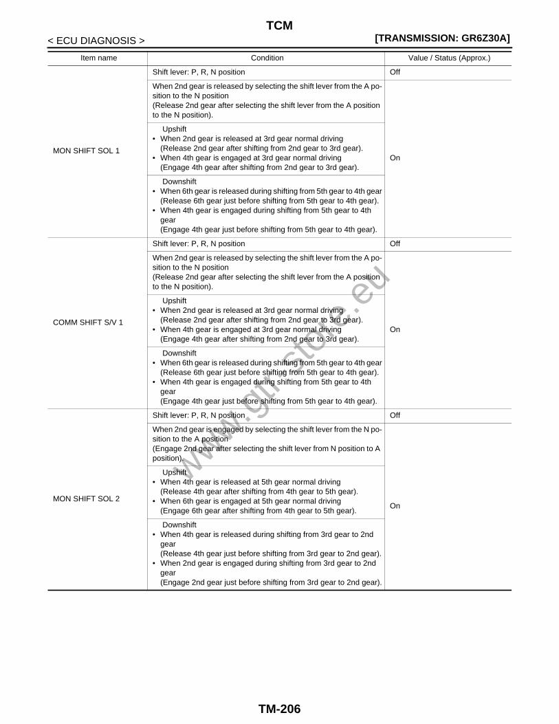
[TRANSMISSION: GR6Z30A]TCM
< ECU DIAGNOSIS >
MON SHIFT SOL 1
Shift lever: P, R, N position Off
When 2nd gear is released by selecting the shift lever from the A po-sition to the N position(Release 2nd gear after selecting the shift lever from the A position to the N position).
On
Upshift• When 2nd gear is released at 3rd gear normal driving
(Release 2nd gear after shifting from 2nd gear to 3rd gear).• When 4th gear is engaged at 3rd gear normal driving
(Engage 4th gear after shifting from 2nd gear to 3rd gear).
Downshift• When 6th gear is released during shifting from 5th gear to 4th gear
(Release 6th gear just before shifting from 5th gear to 4th gear).• When 4th gear is engaged during shifting from 5th gear to 4th
gear(Engage 4th gear just before shifting from 5th gear to 4th gear).
COMM SHIFT S/V 1
Shift lever: P, R, N position Off
When 2nd gear is released by selecting the shift lever from the A po-sition to the N position(Release 2nd gear after selecting the shift lever from the A position to the N position).
On
Upshift• When 2nd gear is released at 3rd gear normal driving
(Release 2nd gear after shifting from 2nd gear to 3rd gear).• When 4th gear is engaged at 3rd gear normal driving
(Engage 4th gear after shifting from 2nd gear to 3rd gear).
Downshift• When 6th gear is released during shifting from 5th gear to 4th gear
(Release 6th gear just before shifting from 5th gear to 4th gear).• When 4th gear is engaged during shifting from 5th gear to 4th
gear(Engage 4th gear just before shifting from 5th gear to 4th gear).
MON SHIFT SOL 2
Shift lever: P, R, N position Off
When 2nd gear is engaged by selecting the shift lever from the N po-sition to the A position(Engage 2nd gear after selecting the shift lever from N position to A position).
On
Upshift• When 4th gear is released at 5th gear normal driving
(Release 4th gear after shifting from 4th gear to 5th gear).• When 6th gear is engaged at 5th gear normal driving
(Engage 6th gear after shifting from 4th gear to 5th gear).
Downshift• When 4th gear is released during shifting from 3rd gear to 2nd
gear(Release 4th gear just before shifting from 3rd gear to 2nd gear).
• When 2nd gear is engaged during shifting from 3rd gear to 2nd gear(Engage 2nd gear just before shifting from 3rd gear to 2nd gear).
Item name Condition Value / Status (Approx.)
www.gtr-
store
.eu
TM-206
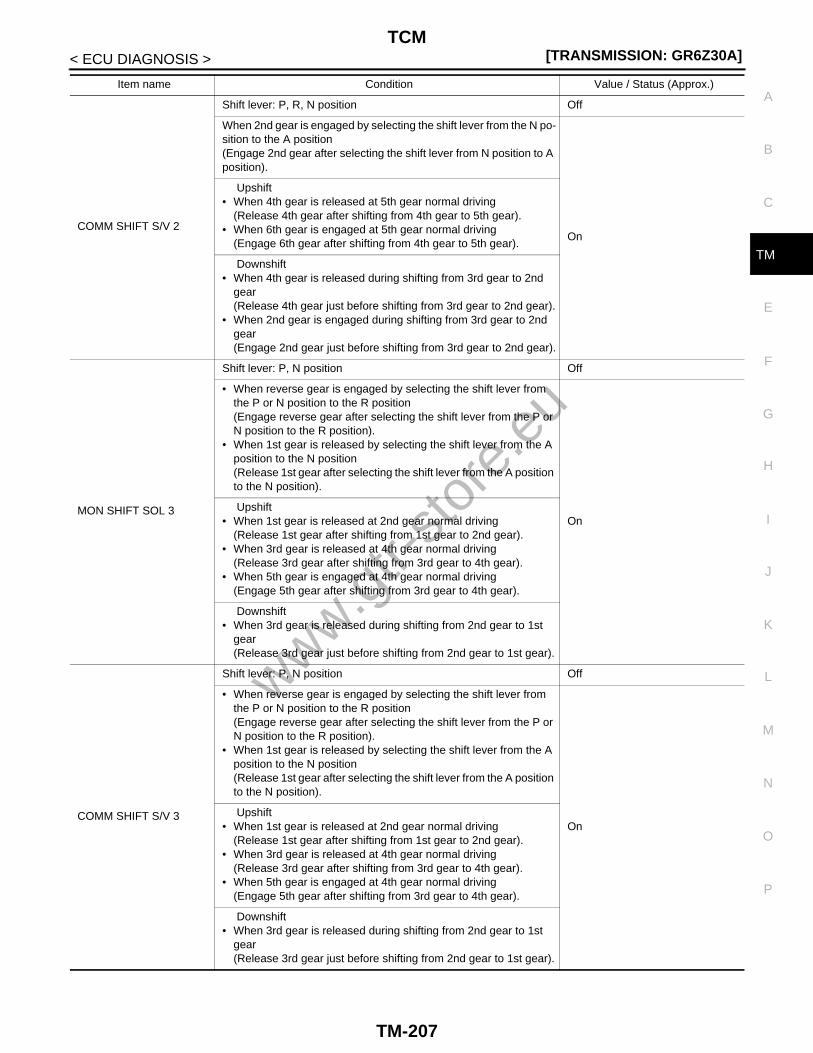
TCM[TRANSMISSION: GR6Z30A]
C
E
F
G
H
I
J
K
L
M
A
B
M
N
O
P
< ECU DIAGNOSIS >
T
COMM SHIFT S/V 2
Shift lever: P, R, N position Off
When 2nd gear is engaged by selecting the shift lever from the N po-sition to the A position(Engage 2nd gear after selecting the shift lever from N position to A position).
On
Upshift• When 4th gear is released at 5th gear normal driving
(Release 4th gear after shifting from 4th gear to 5th gear).• When 6th gear is engaged at 5th gear normal driving
(Engage 6th gear after shifting from 4th gear to 5th gear).
Downshift• When 4th gear is released during shifting from 3rd gear to 2nd
gear(Release 4th gear just before shifting from 3rd gear to 2nd gear).
• When 2nd gear is engaged during shifting from 3rd gear to 2nd gear(Engage 2nd gear just before shifting from 3rd gear to 2nd gear).
MON SHIFT SOL 3
Shift lever: P, N position Off
• When reverse gear is engaged by selecting the shift lever from the P or N position to the R position(Engage reverse gear after selecting the shift lever from the P or N position to the R position).
• When 1st gear is released by selecting the shift lever from the A position to the N position(Release 1st gear after selecting the shift lever from the A position to the N position).
On Upshift
• When 1st gear is released at 2nd gear normal driving(Release 1st gear after shifting from 1st gear to 2nd gear).
• When 3rd gear is released at 4th gear normal driving(Release 3rd gear after shifting from 3rd gear to 4th gear).
• When 5th gear is engaged at 4th gear normal driving(Engage 5th gear after shifting from 3rd gear to 4th gear).
Downshift• When 3rd gear is released during shifting from 2nd gear to 1st
gear(Release 3rd gear just before shifting from 2nd gear to 1st gear).
COMM SHIFT S/V 3
Shift lever: P, N position Off
• When reverse gear is engaged by selecting the shift lever from the P or N position to the R position(Engage reverse gear after selecting the shift lever from the P or N position to the R position).
• When 1st gear is released by selecting the shift lever from the A position to the N position(Release 1st gear after selecting the shift lever from the A position to the N position).
On Upshift
• When 1st gear is released at 2nd gear normal driving(Release 1st gear after shifting from 1st gear to 2nd gear).
• When 3rd gear is released at 4th gear normal driving(Release 3rd gear after shifting from 3rd gear to 4th gear).
• When 5th gear is engaged at 4th gear normal driving(Engage 5th gear after shifting from 3rd gear to 4th gear).
Downshift• When 3rd gear is released during shifting from 2nd gear to 1st
gear(Release 3rd gear just before shifting from 2nd gear to 1st gear).
Item name Condition Value / Status (Approx.)
www.gtr-
store
.eu
TM-207

[TRANSMISSION: GR6Z30A]TCM
< ECU DIAGNOSIS >
MON SHIFT SOL 4
Shift lever: P, N position Off
• When reverse gear is released by selecting the shift lever from the R position to the P or N position(Release reverse gear after selecting the shift lever from the R po-sition to the P or N position.)
• When 1st gear is engaged by selecting the selector gear from the N position to the A position(Engage 1st gear after selecting the shift lever from the N position to the A position).
On Upshift
• When 3rd gear is engaged at 2nd gear normal driving(Engage 3rd gear after shifting from 1st gear to 2nd gear).
Downshift• When 5th gear is released during shifting from 4th gear to 3rd
gear(Release 5th gear just before shifting from 4th gear to 3rd gear).
• When 3rd gear is engaged during shifting from 4th gear to 3rd gear(Engage 3rd gear just before shifting from 4th gear to 3rd gear).
COMM SHIFT S/V 4
Shift lever: P, N position Off
• When reverse gear is released by selecting the shift lever from the R position to the P or N position(Release reverse gear after selecting the shift lever from the R po-sition to the P or N position).
• When 1st gear is engaged by selecting the selector gear from the N position to the A position(Engage 1st gear after selecting the shift lever from the N position to the A position).
On Upshift
• When 3rd gear is engaged at 2nd gear normal driving(Engage 3rd gear after shifting from 1st gear to 2nd gear).
Downshift• When 5th gear is released during shifting from 4th gear to 3rd
gear(Release 5th gear just before shifting from 4th gear to 3rd gear).
• When 3rd gear is engaged during shifting from 4th gear to 3rd gear(Engage 3rd gear just before shifting from 4th gear to 3rd gear).
FLUID TEMPIgnition switch ON(5 seconds or more after turning the ignition switch ON)
The transmission oil temperature in the oil pan is displayed.
FLUID TEMP SEN
Transmission fluid temperature: 20°C (68°F) 1,793 – 1,867 mV
Transmission fluid temperature: 50°C (122°F) 1,096 – 1,150 mV
Transmission fluid temperature: 80°C (176°F) 573 – 617 mV
COMM AXIS A S/V
Shift lever: P, N position(5 seconds or more after the engine is started with the shift lever in the P position and the message “T/M SYSTEM CHECK IN PRO-CESS” is not displayed on the information display)
0.52 – 0.67 A
COMM AXIS B S/V
Shift lever: P, N position(5 seconds or more after the engine is started with the shift lever in the P position and the message “T/M SYSTEM CHECK IN PRO-CESS” is not displayed on the information display)
0.52 – 0.67 A
STOP LAMP SWBrake pedal depressed On
Other than the above Off
Item name Condition Value / Status (Approx.)
www.gtr-
store
.eu
TM-208

TCM[TRANSMISSION: GR6Z30A]
C
E
F
G
H
I
J
K
L
M
A
B
M
N
O
P
< ECU DIAGNOSIS >
T
CLUTCH A PRESS
Shift lever: P, N position(5 seconds or more after the engine is started with the shift lever in the P position and the message “T/M SYSTEM CHECK IN PRO-CESS” is not displayed on the information display)
0.00 MPa
Running with reverse gear, 1st gear, 3rd gear, 5th gear
CLUTCH A SPEED
• Running with 2nd gear• Engine speed: 2,500 rpm or moreCompare the value indicated on CONSULT-III with the value indicat-ed on the tachometer.
It is almost the same engine speed as the value indicated on the ta-chometer.
COM CLUTCH A S/V
Shift lever: P, N position(5 seconds or more after the engine is started with the shift lever in the P position and the message “T/M SYSTEM CHECK IN PRO-CESS” is not displayed on the information display)
0.00 A
Running with reverse gear, 1st gear, 3rd gear, 5th gear
CLUTCH A TEMP Ignition switch ONThe estimate temperature of clutch A is displayed.
CLUTCH B PRESS
Shift lever: P, N position(5 seconds or more after the engine is started with the shift lever in the P position and the message “T/M SYSTEM CHECK IN PRO-CESS” is not displayed on the information display)
0.00 MPa
Running with 2nd gear, 4th gear, 6th gear
CLUTCH B SPEED
• Running with 1st gear• Engine speed: 2500 rpm or moreCompare the value indicated on CONSULT-III with the value indicat-ed on the tachometer.
It is almost the same engine speed as the value indicated on the ta-chometer.
COM CLUTCH B S/V
Shift lever: P, N position(5 seconds or more after the engine is started with the shift lever in the P position and the message “T/M SYSTEM CHECK IN PRO-CESS” is not displayed on the information display)
0.00 A
Running with 2nd gear, 4th gear, 6th gear
CLUTCH B TEMP Ignition switch ONThe estimate temperature of clutch B is displayed.
GR POSITION
Shift lever: P, N position N/P
Shift lever: R position R
While driving 1, 2, 3, 4, 5, 6
ENGINE SPEEDRun the engine and compare the value indicated on CONSULT-III with the value indicated on the tachometer.
It is almost the same engine speed as the value indicated on the ta-chometer.
GR POSI INDICATIONShift lever: P, N position N/P
While driving 1, 2, 3, 4, 5, 6
IGN SWIgnition switch ON On
Ignition switch OFF Off
LINE PRESSURE
• Shift lever: P, N position• At idle• Engine coolant temperature: 60°C (140°F) or more• Transmission oil temperature: 120°C (248°F) or less• Blower motor: OFF• Rear window defogger switch: OFF
0.7 – 1.15 MPa
• Shift lever: P, N position• Transmission oil temperature: 120°C (248°F) or less• Engine speed: 2,000 rpm
0.85 – 1.15 MPa
Item name Condition Value / Status (Approx.)
www.gtr-
store
.eu
TM-209

[TRANSMISSION: GR6Z30A]TCM
< ECU DIAGNOSIS >
COM LINE PRES S/V
• Shift lever: P, N position• At idle• Engine coolant temperature: 60°C (140°F) or more• Transmission oil temperature: 120°C (248°F) or less• Blower motor: OFF• Rear window defogger switch: OFF
0.61 – 0.83 A
• Shift lever: P, N position• Transmission oil temperature: 120°C (248°F) or less• Engine speed: 2,000 rpm
0.61 – 0.78 A
COMM LUBE S/V
• Shift lever: P, N position• At idle• Clutch A temperature: 150°C (302°F) or less• Clutch B temperature: 150°C (302°F) or less
1.20 A
When driving with the throttle opening 2.0/8 0 A
AM RANGE CHG SW 1The shift lever is pressed to the M position side Off
Other than the above On
AM RANGE CHG SW 2The shift lever is pressed to the M position side On
Other than the above Off
MODE
Select the A range A/N
SNOW of set-up switch (transmission) is selected at the A range. (SNOW lamp ON)
A/S
R of set-up switch (transmission) is selected at the A range (R lamp ON)
A/R
Select the M range M/N
R of set-up switch (transmission) is selected at the M range. (R lamp ON)
M/R
COM R MODE LAMPR of set-up switch (transmission) is selected (R lamp ON) On
Other than the above Off
COM S MODE LMPSNOW of set-up switch (transmission) is selected (SNOW lamp ON) On
Other than the above Off
COM NEUTRAL SIGShift lever: P, N position On
Other than the above Off
OUTPUT SHAFT SPD While driving
It is almost the same speed as the value of the clutch A speed or clutch B speed divided by the gear ratio of the driving gear.
PARK POSITION SWShift lever: P position On
Other than the above Off
RANGE
Shift lever: P position P
Shift lever: R position R
Shift lever: N position N
Shift lever: A position A
Shift lever: M position M
COM BACK LMP RLYShift lever: R position On
Other than the above Off
MON BACK LMP RLYShift lever: R position On
Other than the above Off
Item name Condition Value / Status (Approx.)
www.gtr-
store
.eu
TM-210
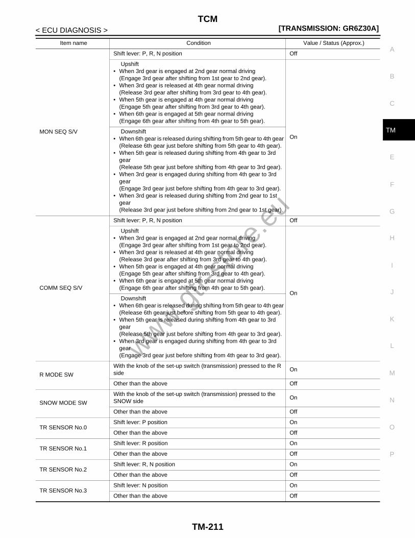
TCM[TRANSMISSION: GR6Z30A]
C
E
F
G
H
I
J
K
L
M
A
B
M
N
O
P
< ECU DIAGNOSIS >
TMON SEQ S/V
Shift lever: P, R, N position Off
Upshift• When 3rd gear is engaged at 2nd gear normal driving
(Engage 3rd gear after shifting from 1st gear to 2nd gear).• When 3rd gear is released at 4th gear normal driving
(Release 3rd gear after shifting from 3rd gear to 4th gear).• When 5th gear is engaged at 4th gear normal driving
(Engage 5th gear after shifting from 3rd gear to 4th gear).• When 6th gear is engaged at 5th gear normal driving
(Engage 6th gear after shifting from 4th gear to 5th gear).
On Downshift
• When 6th gear is released during shifting from 5th gear to 4th gear(Release 6th gear just before shifting from 5th gear to 4th gear).
• When 5th gear is released during shifting from 4th gear to 3rd gear(Release 5th gear just before shifting from 4th gear to 3rd gear).
• When 3rd gear is engaged during shifting from 4th gear to 3rd gear(Engage 3rd gear just before shifting from 4th gear to 3rd gear).
• When 3rd gear is released during shifting from 2nd gear to 1st gear(Release 3rd gear just before shifting from 2nd gear to 1st gear).
COMM SEQ S/V
Shift lever: P, R, N position Off
Upshift• When 3rd gear is engaged at 2nd gear normal driving
(Engage 3rd gear after shifting from 1st gear to 2nd gear).• When 3rd gear is released at 4th gear normal driving
(Release 3rd gear after shifting from 3rd gear to 4th gear).• When 5th gear is engaged at 4th gear normal driving
(Engage 5th gear after shifting from 3rd gear to 4th gear).• When 6th gear is engaged at 5th gear normal driving
(Engage 6th gear after shifting from 4th gear to 5th gear).On
Downshift• When 6th gear is released during shifting from 5th gear to 4th gear
(Release 6th gear just before shifting from 5th gear to 4th gear).• When 5th gear is released during shifting from 4th gear to 3rd
gear(Release 5th gear just before shifting from 4th gear to 3rd gear).
• When 3rd gear is engaged during shifting from 4th gear to 3rd gear(Engage 3rd gear just before shifting from 4th gear to 3rd gear).
R MODE SW
With the knob of the set-up switch (transmission) pressed to the R side
On
Other than the above Off
SNOW MODE SW
With the knob of the set-up switch (transmission) pressed to the SNOW side
On
Other than the above Off
TR SENSOR No.0Shift lever: P position On
Other than the above Off
TR SENSOR No.1Shift lever: R position On
Other than the above Off
TR SENSOR No.2Shift lever: R, N position On
Other than the above Off
TR SENSOR No.3Shift lever: N position On
Other than the above Off
Item name Condition Value / Status (Approx.)
www.gtr-
store
.eu
TM-211

[TRANSMISSION: GR6Z30A]TCM
< ECU DIAGNOSIS >
TERMINAL LAYOUT
PHYSICAL VALUESNOTE:• TCM is installed to the back of the rear seatback. Remove the trim of the trunk room to check the input/out-
put signal. Refer to XX-XX, "*****".
TR SENSOR No.4Shift lever; N, A, M position On
Other than the above Off
TR SENSOR No.5Shift lever: A, M position On
Other than the above Off
VEHICLE SPEEDTurn the drive wheel and compare the value indicated on CON-SULT-III with the value indicated on the speedometer.
It is almost the same speed as the value indicated on the speedome-ter.
COM STARTER RLYShift lever: P, N position On
Other than the above Off
MON STARTER RLYShift lever: P, N position On
Other than the above Off
PADDLE SFT (DOWN)
The paddle shifter (shift-down switch) continues being pulled for-ward
On
Other than the above Off
PADDLE SFT (UP)The paddle shifter (shift-up switch) continues being pulled forward On
Other than the above Off
ACCEL POSI SEN 2 Closed throttle to wide-open throttle 0.0/8 – 8.0/8
BATTERY VOLTAGE Ignition switch ON (engine stopped) Battery voltage (11 – 14 V)
VDC OPERATION SIGVDC activated On
Other than the above Off
TCM RELAY Ignition switch ON On
SHIFT LOCK SOL
“T/M SYSTEM CHECK IN PROCESS” is displayed on the informa-tion display in the combination meter when the shift lever is in P po-sition.
On
Shift lever in any position other than P Off
Item name Condition Value / Status (Approx.)
JMBIA0070ZZ
www.gtr-
store
.eu
TM-212
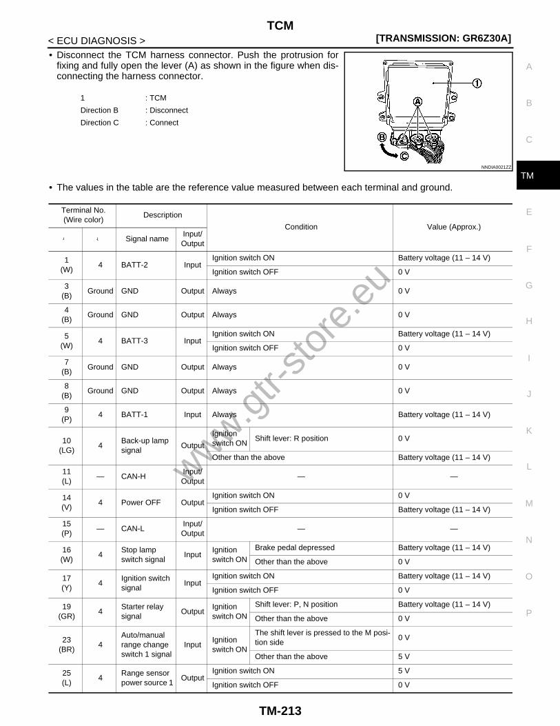
TCM[TRANSMISSION: GR6Z30A]
C
E
F
G
H
I
J
K
L
M
A
B
M
N
O
P
< ECU DIAGNOSIS >
T
• Disconnect the TCM harness connector. Push the protrusion forfixing and fully open the lever (A) as shown in the figure when dis-connecting the harness connector.
• The values in the table are the reference value measured between each terminal and ground.
1 : TCM
Direction B : Disconnect
Direction C : Connect
NNDIA0021ZZ
Terminal No.(Wire color)
Description
Condition Value (Approx.)
+ - Signal nameInput/Output
1(W)
4 BATT-2 InputIgnition switch ON Battery voltage (11 – 14 V)
Ignition switch OFF 0 V
3(B)
Ground GND Output Always 0 V
4(B)
Ground GND Output Always 0 V
5(W)
4 BATT-3 InputIgnition switch ON Battery voltage (11 – 14 V)
Ignition switch OFF 0 V
7(B)
Ground GND Output Always 0 V
8(B)
Ground GND Output Always 0 V
9(P)
4 BATT-1 Input Always Battery voltage (11 – 14 V)
10(LG)
4Back-up lamp signal
Output
Ignition switch ON
Shift lever: R position 0 V
Other than the above Battery voltage (11 – 14 V)
11(L)
— CAN-HInput/Output
— —
14(V)
4 Power OFF OutputIgnition switch ON 0 V
Ignition switch OFF Battery voltage (11 – 14 V)
15(P)
— CAN-LInput/Output
— —
16(W)
4Stop lamp switch signal
InputIgnition switch ON
Brake pedal depressed Battery voltage (11 – 14 V)
Other than the above 0 V
17(Y)
4Ignition switch signal
InputIgnition switch ON Battery voltage (11 – 14 V)
Ignition switch OFF 0 V
19(GR)
4Starter relay signal
OutputIgnition switch ON
Shift lever: P, N position Battery voltage (11 – 14 V)
Other than the above 0 V
23(BR)
4Auto/manual range change switch 1 signal
InputIgnition switch ON
The shift lever is pressed to the M posi-tion side
0 V
Other than the above 5 V
25(L)
4Range sensor power source 1
OutputIgnition switch ON 5 V
Ignition switch OFF 0 V
www.gtr-
store
.eu
TM-213

[TRANSMISSION: GR6Z30A]TCM
< ECU DIAGNOSIS >
26(LG)
4Range sensor power source 2
OutputIgnition switch ON 5 V
Ignition switch OFF 0 V
27(G)
4Range sensor No.0 signal
InputIgnition switch ON
Shift lever: P position 0 V
Other than the above 5 V
28(V)
4Auto/manual range change switch 2 signal
InputIgnition switch ON
The shift lever is pressed to the M posi-tion side
5 V
Other than the above 0 V
31(SB)
4Engine speed signal
Input
After en-gine warming up
At idleNOTE:The pulse period changes depending on the idle speed
1 V*
Engine speed: 2000 rpm
1 V*
33(V)
4Range sensor No.1 signal
InputIgnition switch ON
Shift lever: R position 0 V
Other than the above 5 V
34(O)
4SNOW mode switch signal
InputIgnition switch ON
With the knob of the set-up switch (transmission) pressed to the SNOW side
0 V
Other than the above 5 V
35(G)
4Range sensor No.3 signal
InputIgnition switch ON
Shift lever: N position 0 V
Other than the above 5 V
37(GR)
4R mode switch signal
InputIgnition switch ON
With the knob of the set-up switch (transmission) pressed onto the R side
0 V
Other than the above 5 V
38(R)
4Range sensor No.2 signal
InputIgnition switch ON
Shift lever: R, N position 0 V
Other than the above 5 V
39(W)
4Paddle shifter (shift-up switch) signal
InputIgnition switch ON
The paddle shifter (shift-up switch) con-tinues being pulled forward
0 V
Other than the above Battery voltage (11 – 14 V)
42(L)
4Paddle shifter (shift-down switch) signal
InputIgnition switch ON
The paddle shifter (shift-down switch) continues being pulled forward
0 V
Other than the above Battery voltage (11 – 14 V)
43(P)
4Range sensor No.4 signal
InputIgnition switch ON
Shift lever; N, A, M position 0 V
Other than the above 5 V
44(GR)
4Range sensor No.5 signal
InputIgnition switch ON
Shift lever: A, M position 0 V
Other than the above 5 V
Terminal No.(Wire color)
Description
Condition Value (Approx.)
+ - Signal nameInput/Output
JMBIA0076GB
JMBIA0077GB
www.gtr-
store
.eu
TM-214

TCM[TRANSMISSION: GR6Z30A]
C
E
F
G
H
I
J
K
L
M
A
B
M
N
O
P
< ECU DIAGNOSIS >
T
45(O)
4R mode lamp signal
InputIgnition switch ON
R of set-up switch (transmission) is se-lected (R lamp ON)
0 V
Other than the above Battery voltage (11 – 14 V)
46(W)
4Shift lock sole-noid control signal
OutputIgnition switch ON
• Shift lever: P position• Brake pedal depressed
Battery voltage (11 – 14 V)
Other than the above 0 V
47(G)
4SNOW mode lamp signal
InputIgnition switch ON
SNOW of set-up switch (transmission) is selected (SNOW lamp ON)
0 V
Other than the above Battery voltage (11 – 14 V)
49(L)
4Shift solenoid valve 1 (+)
Output
Engine running
Shift lever: P, R, or N position 0 V
While driving(Other than M range, R mode)
When 2nd gear is released by selecting the shift lever from the A position to the N position(Release 2nd gear after selecting the shift lever from the A position to the N position).
Upshift• When 2nd gear is released at 3rd
gear normal driving(Release 2nd gear after shifting from 2nd gear to 3rd gear).
• When 4th gear is engaged at 3rd gear normal driving(Engage 4th gear after shifting from 2nd gear to 3rd gear).
Downshift• When 6th gear is released during
shifting from 5th gear to 4th gear(Release 6th gear just before shifting from 5th gear to 4th gear).
• When 4th gear is engaged during shifting from 5th gear to 4th gear(Engage 4th gear just before shifting from 5th gear to 4th gear).
Terminal No.(Wire color)
Description
Condition Value (Approx.)
+ - Signal nameInput/Output
NNDIA0131ZZ
www.gtr-
store
.eu
TM-215

[TRANSMISSION: GR6Z30A]TCM
< ECU DIAGNOSIS >
51(P)
4Shift solenoid valve 3 (+)
Output
Engine running
Shift lever: P, N position 0 V
While driving(Other than M range, R mode)
• When reverse gear is engaged by se-lecting the shift lever from the P or N position to the R position(Engage reverse gear after selecting the shift lever from the P or N position to the R position).
• When 1st gear is released by select-ing the shift lever from the A position to the N position(Release 1st gear after selecting the shift lever from the A position to the N position).
Upshift• When 1st gear is released at 2nd
gear normal driving(Release 1st gear after shifting from 1st gear to 2nd gear).
• When 3rd gear is released at 4th gear normal driving(Release 3rd gear after shifting from 3rd gear to 4th gear).
• When 5th gear is engaged at 4th gear normal driving(Engage 5th gear after shifting from 3rd gear to 4th gear).
Downshift• When 3rd gear is released during
shifting from 2nd gear to 1st gear(Release 3rd gear just before shifting from 2nd gear to 1st gear).
Terminal No.(Wire color)
Description
Condition Value (Approx.)
+ - Signal nameInput/Output
NNDIA0131ZZ
www.gtr-
store
.eu
TM-216

TCM[TRANSMISSION: GR6Z30A]
C
E
F
G
H
I
J
K
L
M
A
B
M
N
O
P
< ECU DIAGNOSIS >
T
53(GR)
4Sequence so-lenoid valve (+)
Output
Engine running
Shift lever: P, R, N position 0 V
While driving(Other than the M range, R mode)
Upshift• When 3rd gear is engaged at 2nd
gear normal driving(Engage 3rd gear after shifting from 1st gear to 2nd gear).
• When 3rd gear is released at 4th gear normal driving(Release 3rd gear after shifting from 3rd gear to 4th gear).
• When 5th gear is engaged at 4th gear normal driving(Engage 5th gear after shifting from 3rd gear to 4th gear).
• When 6th gear is engaged at 5th gear normal driving(Engage 6th gear after shifting from 4th gear to 5th gear).
Downshift• When 6th gear is released during
shifting from 5th gear to 4th gear(Release 6th gear just before shifting from 5th gear to 4th gear).
• When 5th gear is released during shifting from 4th gear to 3rd gear(Release 5th gear just before shifting from 4th gear to 3rd gear).
• When 3rd gear is engaged during shifting from 4th gear to 3rd gear(Engage 3rd gear just before shifting from 4th gear to 3rd gear).
• When 3rd gear is released during shifting from 2nd gear to 1st gear(Release 3rd gear just before shifting from 2nd gear to 1st gear).
Terminal No.(Wire color)
Description
Condition Value (Approx.)
+ - Signal nameInput/Output
NNDIA0133ZZ
www.gtr-
store
.eu
TM-217

[TRANSMISSION: GR6Z30A]TCM
< ECU DIAGNOSIS >
54(W)
4Shift solenoid valve 2 (+)
Output
Engine running
Shift lever: P, R, N position 0 V
While driving(Other than the M range, R mode)
When 2nd gear is engaged by selecting the selector gear from the N position to the A position(Engage 2nd gear after selecting the shift lever from the N position to the A position).
Upshift• When 4th gear is released at 5th gear
normal driving(Release 4th gear after shifting from 4th gear to 5th gear).
• When 6th gear is engaged at 5th gear normal driving(Engage 6th gear after shifting from 4th gear to 5th gear).
Downshift• When 4th gear is released during
shifting from 3rd gear to 2nd gear(Release 4th gear just before shifting from 3rd gear to 2nd gear).
• When 2nd gear is engaged during shifting from 3rd gear to 2nd gear(Engage 2nd gear just before shifting from 3rd gear to 2nd gear).
56(LG)
4Shift solenoid valve 4 (+)
Output
Engine running
Shift lever: P, N position 0 V
While driving(Other than M range, R mode)
• When reverse gear is released by se-lecting the shift lever from the R posi-tion to the P or N position(Release reverse gear after selecting the shift lever from the R position to the P or N position).
• When 1st gear is engaged by select-ing the selector gear from the N posi-tion to the A position(Engage 1st gear after selecting the shift lever from the N position to the A position).
Upshift• When 3rd gear is engaged at 2nd
gear normal driving(Engage 3rd gear after shifting from 1st gear to 2nd gear).
Downshift• When 5th gear is released during
shifting from 4th gear to 3rd gear(Release 5th gear just before shifting from 4th gear to 3rd gear).
• When 3rd gear is engaged during shifting from 4th gear to 3rd gear(Engage 3rd gear just before shifting from 4th gear to 3rd gear).
Terminal No.(Wire color)
Description
Condition Value (Approx.)
+ - Signal nameInput/Output
NNDIA0131ZZ
NNDIA0131ZZ
www.gtr-
store
.eu
TM-218

TCM[TRANSMISSION: GR6Z30A]
C
E
F
G
H
I
J
K
L
M
A
B
M
N
O
P
< ECU DIAGNOSIS >
T
57(BR)
4Axis A feed pressure sole-noid valve (+)
OutputEngine running
5 seconds or more after the engine is started with the shift lever in the P posi-tion and the message “T/M SYSTEM CHECK IN PROCESS” is not displayed on the information display
59(G)
4Axis B feed pressure sole-noid valve (+)
OutputEngine running
5 seconds or more after the engine is started with the shift lever in P position and the message “T/M SYSTEM CHECK IN PROCESS” is not displayed on the information display
62(R)
4Axis A feed pressure sole-noid valve (−)
Input Always 0 V
64(O)
4Axis B feed pressure sole-noid valve (−)
Input Always 0 V
66(R)
46th-Neutral po-sition sensor (−)
Input Always 0 V
67(L)
41st-Reverse position sensor 1 signal
Input
Engine running
Shift lever: P, N position 2.19 – 2.88 V
Shift lever: R position 0.68 – 1.76 V
While driving
1st gear 3.34 – 4.41 V
2nd gear, 3rd gear, 4th gear, 5th gear, 6th gear(Other than M range, R mode)
2.19 – 2.88 V
68(BR)
4Clutch A speed sensor (−)
Input Always 0 V
69(Y)
41st-Reverse position sensor 2 (−)
Input Always 0 V
70(W)
46th-Neutral po-sition sensor signal
Input
Engine running
Shift lever: P, R, N position2.19 – 2.88 V
While driving
1st gear, 2nd gear, 3rd gear, 4th gear
5th gear, 6th gear(Other than M range, R mode)
0.68 – 1.76 V
71(Y)
41st-Reverse position sensor 1 (+)
OutputIgnition switch ON 5 V
Ignition switch OFF 0 V
72(G)
4Clutch A speed sensor signal
Input• M range, 2nd gear• Engine speed: 2,000 rpm
Terminal No.(Wire color)
Description
Condition Value (Approx.)
+ - Signal nameInput/Output
NNDIA0054ZZ
NNDIA0054ZZ
NNDIA0061ZZ
www.gtr-
store
.eu
TM-219

[TRANSMISSION: GR6Z30A]TCM
< ECU DIAGNOSIS >
73(Y)
4Line pressure sensor (+)
OutputIgnition switch ON 5 V
Ignition switch OFF 0 V
74(BR)
46th-Neutral po-sition sensor (+)
OutputIgnition switch ON 5 V
Ignition switch OFF 0 V
75(L)
41st-Reverse position sensor 2 (+)
OutputIgnition switch ON 5 V
Ignition switch OFF 0 V
76(Y)
4Clutch A speed sensor (+)
OutputIgnition switch ON 5 V
Ignition switch OFF 0 V
77(GR)
4Line pressure sensor signal
InputEngine running
• Shift lever: P, N position• At idle
0.84 – 1.97 V
78(R)
4Clutch B speed sensor (+)
OutputIgnition switch ON 5 V
Ignition switch OFF 0 V
79(G)
41st-Reverse position sensor 2 signal
Input
Engine running
Shift lever: P, N position 2.19 – 2.88 V
Shift lever: R position 3.34 – 4.41 V
While driving
1st gear 0.68 – 1.76 V
2nd gear, 3rd gear, 4th gear, 5th gear, 6th gear(Other than M range, R mode)
2.19 – 2.88 V
80(BR)
4Line pressure sensor (−)
Input Always 2.19 – 2.88 V
81(G)
42nd-4th posi-tion sensor (+)
OutputIgnition switch ON 5 V
Ignition switch OFF 0 V
82(W)
4Clutch B speed sensor signal
Input• M range, 1st gear• Engine speed: 2,000 rpm
83(L)
42nd-4th posi-tion sensor (−)
Input Always 0 V
84(BR)
43rd-5th posi-tion sensor (−)
Input Always 0 V
85(Y)
42nd-4th posi-tion sensor sig-nal
Input
Engine running
Shift lever: P, R, N position 2.19 – 2.88 V
While driving
1st gear, 2nd gear 0.68 – 1.76 V
3rd gear, 4th gear(Other than M range, R mode)
3.34 – 4.41 V
5th gear, 6th gear(Other than M range, R mode)
2.19 – 2.88 V
86(L)
4Clutch B speed sensor (−)
Input Always 0 V
Terminal No.(Wire color)
Description
Condition Value (Approx.)
+ - Signal nameInput/Output
NNDIA0062ZZwww.gtr-
store
.eu
TM-220

TCM[TRANSMISSION: GR6Z30A]
C
E
F
G
H
I
J
K
L
M
A
B
M
N
O
P
< ECU DIAGNOSIS >
T
87(L)
4Fluid tempera-ture sensor (+)
OutputIgnition switch ON
Transmission fluid temperature: 20°C (68°F)
1.80 – 1.86 V
Transmission fluid temperature: 50°C (122°F)
1.10 – 1.15 V
Transmission fluid temperature: 80°C (176°F)
0.58 – 0.61 V
88(W)
43rd-5th posi-tion sensor (+)
OutputIgnition switch ON 5 V
Ignition switch OFF 0 V
89(O)
4Park position switch signal
InputIgnition switch ON
Shift lever: P position 0 V
Other than the above 5 V
91(SB)
4Fluid tempera-ture sensor (−)
Input Always 0 V
92(R)
43rd-5th posi-tion sensor sig-nal
Input
Engine running
Shift lever: P, R, N position2.19 – 2.88 V
While driving
1st gear
2nd gear, 3rd gear(Other than M range, R mode)
0.68 – 1.76 V
4th gear, 5th gear, 6th gear(Other than M range, R mode)
3.34 – 4.41 V
94(G)
41st-Reverse position sensor 1 (−)
Input Always 0 V
97(BR)
4Clutch A pres-sure sensor (+)
OutputIgnition switch ON 5 V
Ignition switch OFF 0 V
98(R)
4Clutch A pres-sure sensor signal
Input
Engine running
Shift lever: P, R, N position
0.38 – 0.64 VWhile driving
1st gear, 3rd gear, 5th gear
99(W)
4Clutch A pres-sure sensor (−)
Input Always 0 V
102(Y)
4Clutch B pres-sure sensor (+)
OutputIgnition switch ON 5 V
Ignition switch OFF 0 V
103(L)
4Clutch B pres-sure sensor signal
Input
Engine running
Shift lever: P, R, N position
0.38 – 0.64 VWhile driving
2nd gear, 4th gear, 6th gear
104(G)
4Clutch B pres-sure sensor (−)
Input Always 0 V
105(L)
4Output shaft speed sensor (+)
OutputIgnition switch ON 5 V
Ignition switch OFF 0 V
106(G)
4Output shaft speed sensor signal
Input• M range, 1st gear• Engine speed: 2,000 rpm
Terminal No.(Wire color)
Description
Condition Value (Approx.)
+ - Signal nameInput/Output
NNDIA0055ZZ
www.gtr-
store
.eu
TM-221

[TRANSMISSION: GR6Z30A]TCM
< ECU DIAGNOSIS >
*: Average voltage value of pulse waveform (The correct waveform is measured with an oscilloscope)
Wiring Diagram - TRANSMISSION CONTROL SYSTEM - (GT-R certified NISSAN
107(Y)
4Output shaft speed sensor (−)
Input Always 0 V
113(O)
4Line pressure solenoid valve (−)
Input Always 0 V
115(W)
4Lubricating flow solenoid valve (−)
Input Always 0 V
118(V)
4Line pressure solenoid valve (+)
OutputEngine running
• Shift lever: P, N position• At idle
120(BR)
4Lubricating flow solenoid valve (+)
OutputEngine running
• Shift lever: P, N position• At idle
121(R)
4Clutch A sole-noid valve (+)
OutputOther than running with 2nd gear, 4th gear, 6th gear(Clutch A is not engaged)
0 V
123(G)
4Clutch B sole-noid valve (+)
OutputOther than running with reverse gear, 1st gear, 3rd gear, 5th gear(Clutch B is not engaged)
0 V
126(LG)
4Clutch A sole-noid valve (−)
Input Always 0 V
128(Y)
4Clutch B sole-noid valve (−)
Input Always 0 V
Terminal No.(Wire color)
Description
Condition Value (Approx.)
+ - Signal nameInput/Output
NNDIA0056ZZ
NNDIA0057ZZ
www.gtr-
store
.eu
TM-222

TCM[TRANSMISSION: GR6Z30A]
C
E
F
G
H
I
J
K
L
M
A
B
M
N
O
P
< ECU DIAGNOSIS >
T
dealer) INFOID:0000000004020004
JCDWA0235GB
www.gtr-
store
.eu
TM-223

[TRANSMISSION: GR6Z30A]TCM
< ECU DIAGNOSIS >
JCDWA0236GB
www.gtr-
store
.eu
TM-224

TCM[TRANSMISSION: GR6Z30A]
C
E
F
G
H
I
J
K
L
M
A
B
M
N
O
P
< ECU DIAGNOSIS >
T
JCDWA0237GB
www.gtr-
store
.eu
TM-225

[TRANSMISSION: GR6Z30A]TCM
< ECU DIAGNOSIS >
JCDWA0238GB
www.gtr-
store
.eu
TM-226

TCM[TRANSMISSION: GR6Z30A]
C
E
F
G
H
I
J
K
L
M
A
B
M
N
O
P
< ECU DIAGNOSIS >
T
JCDWA0239GB
www.gtr-
store
.eu
TM-227

[TRANSMISSION: GR6Z30A]TCM
< ECU DIAGNOSIS >
JCDWA0240GB
www.gtr-
store
.eu
TM-228

TCM[TRANSMISSION: GR6Z30A]
C
E
F
G
H
I
J
K
L
M
A
B
M
N
O
P
< ECU DIAGNOSIS >
T
JCDWA0241GB
www.gtr-
store
.eu
TM-229

[TRANSMISSION: GR6Z30A]TCM
< ECU DIAGNOSIS >
Fail Safe (GT-R certified NISSAN dealer) INFOID:0000000004020005
PRECAUTION REGARDING FAIL SAFE FUNCTIONSTCM has the electrical fail safe mode. The mode functions so that the operation can be continued even if thesignal circuit of the main electronically controlled input/output parts is damaged.
JCDWA0242GB
www.gtr-
store
.eu
TM-230

TCM[TRANSMISSION: GR6Z30A]
C
E
F
G
H
I
J
K
L
M
A
B
M
N
O
P
< ECU DIAGNOSIS >
T
Even if the electronic circuit is normal, the fail safe mode may start under special conditions (such as when thebrake pedal is depressed suddenly from a hard wheel spin status to stop rotation of wheels). In this case, turnthe ignition switch OFF and back to ON after 5 seconds to resume the normal shift pattern.Consequently, the customer's vehicle may already returns to normal condition. Refer to TM-6, "Work Flow(GT-R certified NISSAN dealer)". Following are results of self-diagnosis.
FAIL SAFE FUNCTIONIf a malfunction occurs in either of the sensors or solenoids, this function controls the normal operation withoutdowngrading the drivability.
DTC No. The transmission operates under the fail safe mode
P0700*1
P0705Release the clutches A and B if an error is detected. The driving force is not transmitted caused by this. The vehicle cannot be driven.
P0770P0882
Driving gear
Fixed into the driving gear to get the vehicle driven, if an error occurs.• When the vehicle starts again after it is stopped, it becomes the following conditions.
Driving gear when the error occurs Restart
1st gearPossible to drive forward only
(fixed into 1st gear)
2nd gearOnly moving forward is possible
(fixed into 2nd gear)
3rd gear, 4th gear, 5th gear, 6th gear, Neutral, Not identified
Impossible
ReverseOnly moving rearward is possible
(fixed into Reverse gear)
Driving mode
• The M range driving is prohibited. (During M range driving, the vehicle is forcibly shifted to the A range driving)
• Selecting the set-up switch is prohibited. (If SNOW or R is selected, the vehicle is forcibly set to Nor-mal)
Vehicle speed
The engine torque is restricted by the driving gear when the error occurs, and then the vehicle speed (maximum speed) is restricted.
Driving gear when the error occurs Vehicle speed km/h (MPH)
1st gear, 2nd gear 46 (29)
3rd gear, 4th gear 85 (53)
5th gear, 6th gear 134 (84)
Reverse 46 (29)
Neutral 134 (84)
Not identified 46 (46)
P0700*2
P0715P0729P0732P0745P0746P0750P0755P0795P0797P0840
Driving gear
• Release the clutch A and prohibit the using of even gears (2nd gear, 4th gear, and 6th gear).• During driving, shift up or down to the next gear (odd gear) according to the driving conditions, and
then shift the gear and drive the vehicle using the odd gears (1st gear, 3rd gear, 5th gear, and Reverse gear).
- Shift to 5th gear after decelerating the vehicle speed to prevent over rev during driving at 6th gear.
Driving mode
• The M range driving is prohibited. (During M range driving, the vehicle is forcibly shifted to the A range driving).
• Selecting the set-up switch is prohibited. (If SNOW or R is selected, the vehicle is forcibly set to Nor-mal).
Vehicle speed
The engine torque is restricted by the driving gear when the error occurs, and then the vehicle speed (maximum speed) is restricted.
Driving gear when the error occurs Vehicle speed km/h (MPH)
2nd gear 46 (29)
4th gear 85 (53)
6th gear 134 (84)
Neutral 134 (84)
Not identified 46 (29)
www.gtr-
store
.eu
TM-231
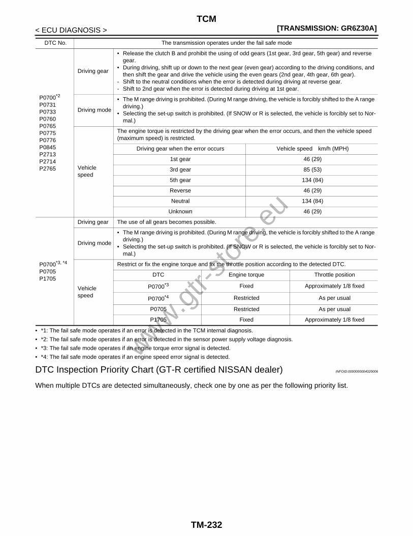
[TRANSMISSION: GR6Z30A]TCM
< ECU DIAGNOSIS >
• *1: The fail safe mode operates if an error is detected in the TCM internal diagnosis.
• *2: The fail safe mode operates if an error is detected in the sensor power supply voltage diagnosis.
• *3: The fail safe mode operates if an engine torque error signal is detected.
• *4: The fail safe mode operates if an engine speed error signal is detected.
DTC Inspection Priority Chart (GT-R certified NISSAN dealer) INFOID:0000000004020006
When multiple DTCs are detected simultaneously, check one by one as per the following priority list.
P0700*2
P0731P0733P0760P0765P0775P0776P0845P2713P2714P2765
Driving gear
• Release the clutch B and prohibit the using of odd gears (1st gear, 3rd gear, 5th gear) and reverse gear.
• During driving, shift up or down to the next gear (even gear) according to the driving conditions, and then shift the gear and drive the vehicle using the even gears (2nd gear, 4th gear, 6th gear).
- Shift to the neutral conditions when the error is detected during driving at reverse gear.- Shift to 2nd gear when the error is detected during driving at 1st gear.
Driving mode
• The M range driving is prohibited. (During M range driving, the vehicle is forcibly shifted to the A range driving.)
• Selecting the set-up switch is prohibited. (If SNOW or R is selected, the vehicle is forcibly set to Nor-mal.)
Vehicle speed
The engine torque is restricted by the driving gear when the error occurs, and then the vehicle speed (maximum speed) is restricted.
Driving gear when the error occurs Vehicle speed km/h (MPH)
1st gear 46 (29)
3rd gear 85 (53)
5th gear 134 (84)
Reverse 46 (29)
Neutral 134 (84)
Unknown 46 (29)
P0700*3, *4
P0705P1705
Driving gear The use of all gears becomes possible.
Driving mode
• The M range driving is prohibited. (During M range driving, the vehicle is forcibly shifted to the A range driving.)
• Selecting the set-up switch is prohibited. (If SNOW or R is selected, the vehicle is forcibly set to Nor-mal.)
Vehicle speed
Restrict or fix the engine torque and fix the throttle position according to the detected DTC.
DTC Engine torque Throttle position
P0700*3 Fixed Approximately 1/8 fixed
P0700*4 Restricted As per usual
P0705 Restricted As per usual
P1705 Fixed Approximately 1/8 fixed
DTC No. The transmission operates under the fail safe mode
www.gtr-
store
.eu
TM-232

TCM[TRANSMISSION: GR6Z30A]
C
E
F
G
H
I
J
K
L
M
A
B
M
N
O
P
< ECU DIAGNOSIS >
T
DTC Index INFOID:0000000004020007
Priority Detected items (DTC)
1 • U1000 CAN COMM CIRC
2 • P0700 TCM• P0705 PNP SW/CIRC• P0706 TR SENSOR A CIRCUIT• P0715 INPUT SPD SEN/CIRC• P0720 VEH SPD SEN/CIR AT• P0750 SHIFT SOL A• P0755 SHIFT SOL B• P0760 SHIFT SOL C• P0765 SHIFT SOL D• P0770 SHIFT SOL E• P0790 NRML/PERFORM SW CIRC• P0827 UP and DOWN SFT SW CIRC• P0828 UP and DOWN SFT SW CIRC• P1705 TP SEN/CIRC A/T• P2713 PRESS CONTROL SOL D• P2765 INP/TRBN SPD SEN B CIR
3 • P0710 ATF TEMP SEN/CIRC• P0725 ENGINE SPEED SIG• P0729 A/T 6ST GR FNCTN• P0731 A/T 1ST GR FNCTN• P0732 A/T 2ND GR FNCTN• P0733 A/T 3RD GR FNCTN• P0745 L/PRESS SOL/CIRC• P0775 PC SOL B(SFT/PRS)• P0795 PC SOL C(TCC&SFT)• P0840 TR PRS SENS/A CIRC• P0845 TR PRS SENS/B CIRC• P0872 TFP SENSOR/SW C CIRC• P0873 TFP SENSOR/SW C CIRC• P0882 TCM POWER INPT SIG• P2722 PRESS CONTROL SOL E• P2731 PRESS CONTROL SOL F• P2776 UPSHIFT SW CIRCUIT• P2780 DOWNSHIFT SW CIRCUIT
4 • P0711 FLUID TEMP SEN• P0746 PRS CNT SOL/A FCTN• P0776 PRS CNT SOL/B FCTN• P0797 PC SOL C STC ON• P2714 PRESS CONTROL SOL D
DTC*
Item(CONSULT-III screen terms)
Transmission warn-ing light
Reference“TRANSMISSION” with CONSULT-III
MIL, “ENGINE” with CONSULT-III or
GST
P0700 P0700 TCM Blinking TM-58
P0705 P0705 PNP SW/CIRC Blinking TM-62
P0706 — TR SENSOR A CIRCUIT — TM-68
P0710 P0710 ATF TEMP SEN/CIRC — TM-73
P0711 P0711 FLUID TEMP SEN — TM-76
P0715 P0715 INPUT SPD SEN/CIRC Blinking TM-79
P0720 P0720 VEH SPD SEN/CIR AT — TM-82
P0725 — ENGINE SPEED SIG — TM-87
P0729 P0729 A/T 6ST GR FNCTN Blinking TM-91
www.gtr-
store
.eu
TM-233
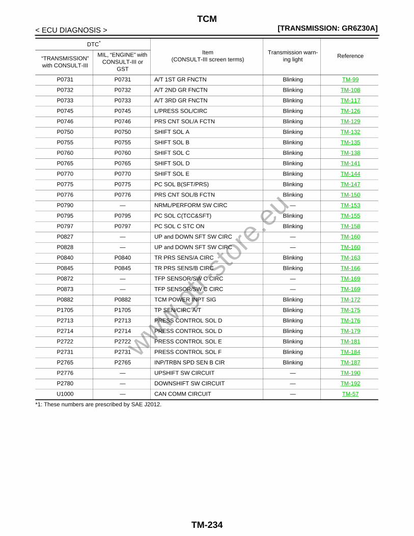
[TRANSMISSION: GR6Z30A]TCM
< ECU DIAGNOSIS >
*1: These numbers are prescribed by SAE J2012.
P0731 P0731 A/T 1ST GR FNCTN Blinking TM-99
P0732 P0732 A/T 2ND GR FNCTN Blinking TM-108
P0733 P0733 A/T 3RD GR FNCTN Blinking TM-117
P0745 P0745 L/PRESS SOL/CIRC Blinking TM-126
P0746 P0746 PRS CNT SOL/A FCTN Blinking TM-129
P0750 P0750 SHIFT SOL A Blinking TM-132
P0755 P0755 SHIFT SOL B Blinking TM-135
P0760 P0760 SHIFT SOL C Blinking TM-138
P0765 P0765 SHIFT SOL D Blinking TM-141
P0770 P0770 SHIFT SOL E Blinking TM-144
P0775 P0775 PC SOL B(SFT/PRS) Blinking TM-147
P0776 P0776 PRS CNT SOL/B FCTN Blinking TM-150
P0790 — NRML/PERFORM SW CIRC — TM-153
P0795 P0795 PC SOL C(TCC&SFT) Blinking TM-155
P0797 P0797 PC SOL C STC ON Blinking TM-158
P0827 — UP and DOWN SFT SW CIRC — TM-160
P0828 — UP and DOWN SFT SW CIRC — TM-160
P0840 P0840 TR PRS SENS/A CIRC Blinking TM-163
P0845 P0845 TR PRS SENS/B CIRC Blinking TM-166
P0872 — TFP SENSOR/SW C CIRC — TM-169
P0873 — TFP SENSOR/SW C CIRC — TM-169
P0882 P0882 TCM POWER INPT SIG Blinking TM-172
P1705 P1705 TP SEN/CIRC A/T Blinking TM-175
P2713 P2713 PRESS CONTROL SOL D Blinking TM-176
P2714 P2714 PRESS CONTROL SOL D Blinking TM-179
P2722 P2722 PRESS CONTROL SOL E Blinking TM-181
P2731 P2731 PRESS CONTROL SOL F Blinking TM-184
P2765 P2765 INP/TRBN SPD SEN B CIR Blinking TM-187
P2776 — UPSHIFT SW CIRCUIT — TM-190
P2780 — DOWNSHIFT SW CIRCUIT — TM-192
U1000 — CAN COMM CIRCUIT — TM-57
DTC*
Item(CONSULT-III screen terms)
Transmission warn-ing light
Reference“TRANSMISSION” with CONSULT-III
MIL, “ENGINE” with CONSULT-III or
GST
www.gtr-
store
.eu
TM-234

TRANSMISSION CONTROL SYSTEM[TRANSMISSION: GR6Z30A]
C
E
F
G
H
I
J
K
L
M
A
B
M
N
O
P
< SYMPTOM DIAGNOSIS >
T
SYMPTOM DIAGNOSISTRANSMISSION CONTROL SYSTEM
Symptom Table (GT-R certified NISSAN dealer) INFOID:0000000004020008
This chart is classified into “output device system”, “intermediate device/check and test/adjustment system”,“output signal system”, “input signal system” and “part check and replacement” per symptom. Checking all theclassifications in numerical order allows you to find malfunctions efficiently.
Output device system
Items
Clu
tch
A
Clu
tch
B
6th-
N s
hift
actu
ator
2nd-
4th
shift
act
uato
r
1st-
Rev
erse
shi
ft ac
tuat
or
3rd-
5th
shift
act
uato
r
Clu
tch
lubr
icat
ion
Gea
r lu
bric
atio
n
Par
king
Shi
ft lo
ck d
evic
e
Ran
ge in
dica
tor
Shi
ft po
sitio
n in
dica
tor
Tra
nsm
issi
on w
arni
ng li
ght
Mul
tifun
ctio
n di
spla
y
Info
rmat
ion
disp
lay
Reference
TM
-291
TM
-291
TM
-291
TM
-291
TM
-291
TM
-291
TM
-291
TM
-291
TM
-291
TM
-200
XX
-XX
, "**
***"
XX
-XX
, "**
***"
XX
-XX
, "**
***"
XX
-XX
, "**
***"
, XX
-XX
, "**
***"
XX
-XX
, "**
***"
Shock generated at shifting is great 1 2
Creep is great
1st gear 1 2
2nd gear 1 2
Reverse 1 2
The gear is hard to engage or the gearshift is slow(The position lamp blinks at M range or re-verse gear)
→1st gear 1 2
→2nd gear 1 2
→3rd gear 2 1
→4th gear 2 1
→5th gear 2 1
→6th gear 1 2
→Reverse gear 1
www.gtr-
store
.eu
TM-235

[TRANSMISSION: GR6Z30A]TRANSMISSION CONTROL SYSTEM
< SYMPTOM DIAGNOSIS >
Start and lockup
The engine races or the clutch slips
1st gear 1
2nd gear 1
3rd gear 1
4th gear 1
5th gear 1
6th gear 1
Reverse 1
Noise and vibration are great
1st gear 1 2
2nd gear 1 2
3rd gear 1 2
4th gear 1 2
5th gear 1 2
6th gear 1 2
Reverse 1 2
When shifting gears
The engine races or the clutch slips
→1st gear 1
→2nd gear 1
→3rd gear 1
→4th gear 1
→5th gear 1
→6th gear 1
Noise and vibration are great
→1st gear 1 2
→2nd gear 1 2
→3rd gear 1 2
→4th gear 1 2
→5th gear 1 2
→6th gear 1 2
Items
Clu
tch
A
Clu
tch
B
6th-
N s
hift
actu
ator
2nd-
4th
shift
act
uato
r
1st-
Rev
erse
shi
ft ac
tuat
or
3rd-
5th
shift
act
uato
r
Clu
tch
lubr
icat
ion
Gea
r lu
bric
atio
n
Par
king
Shi
ft lo
ck d
evic
e
Ran
ge in
dica
tor
Shi
ft po
sitio
n in
dica
tor
Tra
nsm
issi
on w
arni
ng li
ght
Mul
tifun
ctio
n di
spla
y
Info
rmat
ion
disp
lay
Reference
TM
-291
TM
-291
TM
-291
TM
-291
TM
-291
TM
-291
TM
-291
TM
-291
TM
-291
TM
-200
XX
-XX
, "**
***"
XX
-XX
, "**
***"
XX
-XX
, "**
***"
XX
-XX
, "**
***"
, XX
-XX
, "**
***"
XX
-XX
, "**
***"
www.gtr-
store
.eu
TM-236

TRANSMISSION CONTROL SYSTEM[TRANSMISSION: GR6Z30A]
C
E
F
G
H
I
J
K
L
M
A
B
M
N
O
P
< SYMPTOM DIAGNOSIS >
T
Learning error
Clutch touch pointClutch A 1
Clutch B 1
Gear position sen-sor
1st gear 1
2nd gear 1
3rd gear 1
4th gear 1
5th gear 1
6th gear 1
Reverse 1
The noise and vibration 1
Oil leakage
Shift lock error 1
Poor starting engine
Back-up lamp ON error
Items
Clu
tch
A
Clu
tch
B
6th-
N s
hift
actu
ator
2nd-
4th
shift
act
uato
r
1st-
Rev
erse
shi
ft ac
tuat
or
3rd-
5th
shift
act
uato
r
Clu
tch
lubr
icat
ion
Gea
r lu
bric
atio
n
Par
king
Shi
ft lo
ck d
evic
e
Ran
ge in
dica
tor
Shi
ft po
sitio
n in
dica
tor
Tra
nsm
issi
on w
arni
ng li
ght
Mul
tifun
ctio
n di
spla
y
Info
rmat
ion
disp
lay
Reference
TM
-291
TM
-291
TM
-291
TM
-291
TM
-291
TM
-291
TM
-291
TM
-291
TM
-291
TM
-200
XX
-XX
, "**
***"
XX
-XX
, "**
***"
XX
-XX
, "**
***"
XX
-XX
, "**
***"
, XX
-XX
, "**
***"
XX
-XX
, "**
***"
www.gtr-
store
.eu
TM-237

[TRANSMISSION: GR6Z30A]TRANSMISSION CONTROL SYSTEM
< SYMPTOM DIAGNOSIS >
Display/illumination er-ror
Set-up switch
R mode lamp 1
SNOW mode lamp
1
Shift position indicator 1
Transmission warning light 1
Multi-function dis-play
Gear position 1
A/M range 1
Transmission oil pressure
1
Transmission oil temperature
1
Information display
SHIFT TO THE P RANGE
1
CHECK POSI-TION OF SHIFT LEVER
1
T/M OIL TEMP HIGH DE-CREASE SPEED
1
T/M CLUTCH TEMP HIGH STOP VEHI-CLE UNTIL WARNING TURNS OFF
1
T/M SYSTEM MALFUNC-TION VISIT DEALER
1
T/M SYSTEM CHECK IN PROCESS
1
Shift leverRange change error
A/M range change error
Items
Clu
tch
A
Clu
tch
B
6th-
N s
hift
actu
ator
2nd-
4th
shift
act
uato
r
1st-
Rev
erse
shi
ft ac
tuat
or
3rd-
5th
shift
act
uato
r
Clu
tch
lubr
icat
ion
Gea
r lu
bric
atio
n
Par
king
Shi
ft lo
ck d
evic
e
Ran
ge in
dica
tor
Shi
ft po
sitio
n in
dica
tor
Tra
nsm
issi
on w
arni
ng li
ght
Mul
tifun
ctio
n di
spla
y
Info
rmat
ion
disp
lay
Reference
TM
-291
TM
-291
TM
-291
TM
-291
TM
-291
TM
-291
TM
-291
TM
-291
TM
-291
TM
-200
XX
-XX
, "**
***"
XX
-XX
, "**
***"
XX
-XX
, "**
***"
XX
-XX
, "**
***"
, XX
-XX
, "**
***"
XX
-XX
, "**
***"
www.gtr-
store
.eu
TM-238

TRANSMISSION CONTROL SYSTEM[TRANSMISSION: GR6Z30A]
C
E
F
G
H
I
J
K
L
M
A
B
M
N
O
P
< SYMPTOM DIAGNOSIS >
T
Intermediate device/check and test/adjustment system
Paddle shifterUp switch error
Down switch error
Set-up switch error
Items
Bac
k-up
lam
p re
lay
Sta
rter
rel
ay
Oil
leak
age
(oil
leve
l)
Oil
stat
us
Gea
r po
sitio
n te
st o
r di
seng
agin
g th
e ge
ar
Clu
tch
gear
lear
ning
Clu
tch
touc
h po
int
Adj
ust c
lutc
h ca
paci
tyReference
XX
-XX
, "**
***"
XX
-XX
, "**
***"
TM
-265
TM
-265
TM
-41
TM
-41
TM
-41
TM
-41
Shock generated at shifting is great 1 2
Creep is great
1st gear 1 2
2nd gear 1 2
Reverse 1 2
The gear is hard to engage or the gearshift is slow(The position lamp blinks at M range or re-verse gear)
→1st gear 1 2 1
→2nd gear 1 2 1
→3rd gear 1 2 1
→4th gear 1 2 1
→5th gear 1 2 1
→6th gear 1 2 1
→Reverse gear 1 2 1
Items
Clu
tch
A
Clu
tch
B
6th-
N s
hift
actu
ator
2nd-
4th
shift
act
uato
r
1st-
Rev
erse
shi
ft ac
tuat
or
3rd-
5th
shift
act
uato
r
Clu
tch
lubr
icat
ion
Gea
r lu
bric
atio
n
Par
king
Shi
ft lo
ck d
evic
e
Ran
ge in
dica
tor
Shi
ft po
sitio
n in
dica
tor
Tra
nsm
issi
on w
arni
ng li
ght
Mul
tifun
ctio
n di
spla
y
Info
rmat
ion
disp
lay
Reference
TM
-291
TM
-291
TM
-291
TM
-291
TM
-291
TM
-291
TM
-291
TM
-291
TM
-291
TM
-200
XX
-XX
, "**
***"
XX
-XX
, "**
***"
XX
-XX
, "**
***"
XX
-XX
, "**
***"
, XX
-XX
, "**
***"
XX
-XX
, "**
***"
www.gtr-
store
.eu
TM-239

[TRANSMISSION: GR6Z30A]TRANSMISSION CONTROL SYSTEM
< SYMPTOM DIAGNOSIS >
Start and lockup
The engine races or the clutch slips
1st gear 1 2 2 1
2nd gear 1 2 2 1
3rd gear 1 2 2 1
4th gear 1 2 2 1
5th gear 1 2 2 1
6th gear 1 2 2 1
Reverse 1 2 2 1
Noise and vibration are great
1st gear 1 2 2
2nd gear 1 2 2
3rd gear 1 2 2
4th gear 1 2 2
5th gear 1 2 2
6th gear 1 2 2
Reverse 1 2 2
When shifting gears
The engine races or the clutch slips
→1st gear 1 2 1 3 2
→2nd gear 1 2 1 3 2
→3rd gear 1 2 1 3 2
→4th gear 1 2 1 3 2
→5th gear 1 2 1 3 2
→6th gear 1 2 1 3 2
Noise and vibration are great
→1st gear 1 2 1 3 2
→2nd gear 1 2 1 3 2
→3rd gear 1 2 1 3 2
→4th gear 1 2 1 3 2
→5th gear 1 2 1 3 2
→6th gear 1 2 1 3 2
Items
Bac
k-up
lam
p re
lay
Sta
rter
rel
ay
Oil
leak
age
(oil
leve
l)
Oil
stat
us
Gea
r po
sitio
n te
st o
r di
seng
agin
g th
e ge
ar
Clu
tch
gear
lear
ning
Clu
tch
touc
h po
int
Adj
ust c
lutc
h ca
paci
ty
Reference
XX
-XX
, "**
***"
XX
-XX
, "**
***"
TM
-265
TM
-265
TM
-41
TM
-41
TM
-41
TM
-41
www.gtr-
store
.eu
TM-240

TRANSMISSION CONTROL SYSTEM[TRANSMISSION: GR6Z30A]
C
E
F
G
H
I
J
K
L
M
A
B
M
N
O
P
< SYMPTOM DIAGNOSIS >
T
Learning error
Clutch touch pointClutch A 1 1
Clutch B 1 1
Gear position sen-sor
1st gear 1 2 1
2nd gear 1 2 1
3rd gear 1 2 1
4th gear 1 2 1
5th gear 1 2 1
6th gear 1 2 1
Reverse 1 2 1
The noise and vibration are generated 1 2
Oil leakage occurs 1
Shift lock error
Poor starting engine 1
Back-up lamp ON error 1
Items
Bac
k-up
lam
p re
lay
Sta
rter
rel
ay
Oil
leak
age
(oil
leve
l)
Oil
stat
us
Gea
r po
sitio
n te
st o
r di
seng
agin
g th
e ge
ar
Clu
tch
gear
lear
ning
Clu
tch
touc
h po
int
Adj
ust c
lutc
h ca
paci
ty
Reference
XX
-XX
, "**
***"
XX
-XX
, "**
***"
TM
-265
TM
-265
TM
-41
TM
-41
TM
-41
TM
-41
www.gtr-
store
.eu
TM-241

[TRANSMISSION: GR6Z30A]TRANSMISSION CONTROL SYSTEM
< SYMPTOM DIAGNOSIS >
Display/illumination er-ror
Set-up switch
R mode lamp
SNOW mode lamp
Shift position indicator
Transmission warning light
Multifunction dis-play
Gear position
A/M range
Transmission oil pressure
Transmission oil temperature
Information display
SHIFT TO THE P RANGE
CHECK POSI-TION OF SHIFT LEVER
T/M OIL TEMP HIGH DE-CREASE SPEED
T/M CLUTCH TEMP HIGH STOP VEHI-CLE UNTIL WARNING TURNS OFF
T/M SYSTEM MALFUNC-TION VISIT DEALER
T/M SYSTEM CHECK IN PROCESS
Shift leverRange change error
A/M range change error
Items
Bac
k-up
lam
p re
lay
Sta
rter
rel
ay
Oil
leak
age
(oil
leve
l)
Oil
stat
us
Gea
r po
sitio
n te
st o
r di
seng
agin
g th
e ge
ar
Clu
tch
gear
lear
ning
Clu
tch
touc
h po
int
Adj
ust c
lutc
h ca
paci
ty
Reference
XX
-XX
, "**
***"
XX
-XX
, "**
***"
TM
-265
TM
-265
TM
-41
TM
-41
TM
-41
TM
-41
www.gtr-
store
.eu
TM-242

TRANSMISSION CONTROL SYSTEM[TRANSMISSION: GR6Z30A]
C
E
F
G
H
I
J
K
L
M
A
B
M
N
O
P
< SYMPTOM DIAGNOSIS >
T
Output signal system
Paddle shifterUp switch error
Down switch error
Set-up switch error
Items
Clu
tch
A p
ress
ure
S/V
Clu
tch
B p
ress
ure
S/V
Line
pre
ssur
e S
/V
Lubr
icat
ing
flow
S/V
Shi
ft S
/V 1
Shi
ft S
/V 2
Shi
ft S
/V 3
Shi
ft S
/V 4
Seq
uenc
e S
/V
Axi
s A
feed
pre
ssur
e S
/V
Axi
s B
feed
pre
ssur
e S
/V
Shi
ft lo
ck s
olen
oid
R la
mp
(Set
-up
switc
h)
SN
OW
lam
p (S
et-u
p sw
itch)
Bac
k-up
lam
p re
lay
Sta
rter
rel
ay
Com
bina
tion
met
er
EC
M (
Tor
que
requ
est)
Reference
TM
-126
TM
-147
TM
-184
TM
-181
TM
-132
TM
-135
TM
-138
TM
-141
TM
-144
TM
-155
TM
-176
TM
-200
TM
-197
TM
-197
XX
-XX
, "**
***"
XX
-XX
, "**
***"
XX
-XX
, "**
***"
TM
-57
Shock generated at shifting is great 1 2
Creep is great
1st gear 1 2
2nd gear 1 2
Reverse 1 2
The gear is hard to engage or the gearshift is slow(The position lamp blinks at M range or reverse gear)
→1st gear 5 3 1 2 4
→2nd gear 5 3 1 2 4
→3rd gear 5 3 1 2 4
→4th gear 5 1 3 2 4
→5th gear 5 1 3 2 4
→6th gear 5 3 1 2 4
→Reverse gear 5 1 3 2 4
Items
Bac
k-up
lam
p re
lay
Sta
rter
rel
ay
Oil
leak
age
(oil
leve
l)
Oil
stat
us
Gea
r po
sitio
n te
st o
r di
seng
agin
g th
e ge
ar
Clu
tch
gear
lear
ning
Clu
tch
touc
h po
int
Adj
ust c
lutc
h ca
paci
ty
Reference
XX
-XX
, "**
***"
XX
-XX
, "**
***"
TM
-265
TM
-265
TM
-41
TM
-41
TM
-41
TM
-41
www.gtr-
store
.eu
TM-243
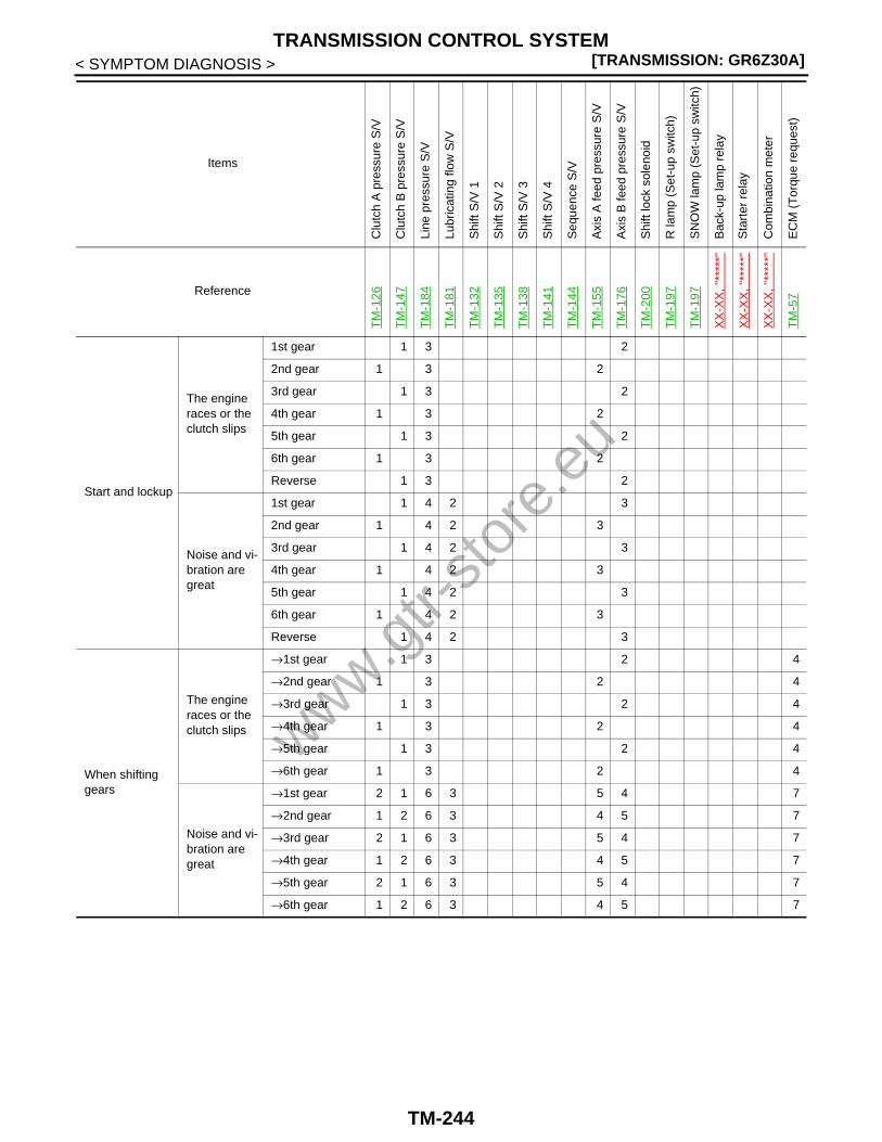
[TRANSMISSION: GR6Z30A]TRANSMISSION CONTROL SYSTEM
< SYMPTOM DIAGNOSIS >
Start and lockup
The engine races or the clutch slips
1st gear 1 3 2
2nd gear 1 3 2
3rd gear 1 3 2
4th gear 1 3 2
5th gear 1 3 2
6th gear 1 3 2
Reverse 1 3 2
Noise and vi-bration are great
1st gear 1 4 2 3
2nd gear 1 4 2 3
3rd gear 1 4 2 3
4th gear 1 4 2 3
5th gear 1 4 2 3
6th gear 1 4 2 3
Reverse 1 4 2 3
When shifting gears
The engine races or the clutch slips
→1st gear 1 3 2 4
→2nd gear 1 3 2 4
→3rd gear 1 3 2 4
→4th gear 1 3 2 4
→5th gear 1 3 2 4
→6th gear 1 3 2 4
Noise and vi-bration are great
→1st gear 2 1 6 3 5 4 7
→2nd gear 1 2 6 3 4 5 7
→3rd gear 2 1 6 3 5 4 7
→4th gear 1 2 6 3 4 5 7
→5th gear 2 1 6 3 5 4 7
→6th gear 1 2 6 3 4 5 7
Items
Clu
tch
A p
ress
ure
S/V
Clu
tch
B p
ress
ure
S/V
Line
pre
ssur
e S
/V
Lubr
icat
ing
flow
S/V
Shi
ft S
/V 1
Shi
ft S
/V 2
Shi
ft S
/V 3
Shi
ft S
/V 4
Seq
uenc
e S
/V
Axi
s A
feed
pre
ssur
e S
/V
Axi
s B
feed
pre
ssur
e S
/V
Shi
ft lo
ck s
olen
oid
R la
mp
(Set
-up
switc
h)
SN
OW
lam
p (S
et-u
p sw
itch)
Bac
k-up
lam
p re
lay
Sta
rter
rel
ay
Com
bina
tion
met
er
EC
M (
Tor
que
requ
est)
Reference
TM
-126
TM
-147
TM
-184
TM
-181
TM
-132
TM
-135
TM
-138
TM
-141
TM
-144
TM
-155
TM
-176
TM
-200
TM
-197
TM
-197
XX
-XX
, "**
***"
XX
-XX
, "**
***"
XX
-XX
, "**
***"
TM
-57
www.gtr-
store
.eu
TM-244

TRANSMISSION CONTROL SYSTEM[TRANSMISSION: GR6Z30A]
C
E
F
G
H
I
J
K
L
M
A
B
M
N
O
P
< SYMPTOM DIAGNOSIS >
T
Learning error
Clutch touch point
Clutch A 1 3 2
Clutch B 1 3 2
Gear position sensor
1st gear 5 3 1 2 4
2nd gear 5 3 1 2 4
3rd gear 5 3 1 2 4
4th gear 5 1 3 2 4
5th gear 5 1 3 2 4
6th gear 5 3 1 2 4
Reverse 5 1 3 2 4
The noise and vibration are generated 1
Oil leakage occurs
Shift lock error 2 2 1
Poor starting engine 1
Back-up lamp ON error 1
Items
Clu
tch
A p
ress
ure
S/V
Clu
tch
B p
ress
ure
S/V
Line
pre
ssur
e S
/V
Lubr
icat
ing
flow
S/V
Shi
ft S
/V 1
Shi
ft S
/V 2
Shi
ft S
/V 3
Shi
ft S
/V 4
Seq
uenc
e S
/V
Axi
s A
feed
pre
ssur
e S
/V
Axi
s B
feed
pre
ssur
e S
/V
Shi
ft lo
ck s
olen
oid
R la
mp
(Set
-up
switc
h)
SN
OW
lam
p (S
et-u
p sw
itch)
Bac
k-up
lam
p re
lay
Sta
rter
rel
ay
Com
bina
tion
met
er
EC
M (
Tor
que
requ
est)
Reference
TM
-126
TM
-147
TM
-184
TM
-181
TM
-132
TM
-135
TM
-138
TM
-141
TM
-144
TM
-155
TM
-176
TM
-200
TM
-197
TM
-197
XX
-XX
, "**
***"
XX
-XX
, "**
***"
XX
-XX
, "**
***"
TM
-57
www.gtr-
store
.eu
TM-245

[TRANSMISSION: GR6Z30A]TRANSMISSION CONTROL SYSTEM
< SYMPTOM DIAGNOSIS >
Display/illumina-tion error
Set-up switch
R mode lamp 1
SNOW mode lamp
1
Shift position indicator 1
Transmission warning light 1
Multifunction display
Gear position 1
A/M range 1
Transmission oil pressure
1
Transmission oil temperature
1
Information display
SHIFT TO P RANGE
1
CHECK POSI-TION OF SHIFT LEVER
1
T/M OIL TEMP HIGH DE-CREASE SPEED
1
T/M CLUTCH TEMP HIGH STOP VEHI-CLE UNTIL WARNING TURNS OFF
1
T/M SYSTEM MALFUNC-TION VISIT DEALER
1
T/M SYSTEM CHECK IN PROCESS
1 2
Shift leverRange change error
A/M range change error
Paddle shifterUp switch error
Down switch error
Set-up switch error
Items
Clu
tch
A p
ress
ure
S/V
Clu
tch
B p
ress
ure
S/V
Line
pre
ssur
e S
/V
Lubr
icat
ing
flow
S/V
Shi
ft S
/V 1
Shi
ft S
/V 2
Shi
ft S
/V 3
Shi
ft S
/V 4
Seq
uenc
e S
/V
Axi
s A
feed
pre
ssur
e S
/V
Axi
s B
feed
pre
ssur
e S
/V
Shi
ft lo
ck s
olen
oid
R la
mp
(Set
-up
switc
h)
SN
OW
lam
p (S
et-u
p sw
itch)
Bac
k-up
lam
p re
lay
Sta
rter
rel
ay
Com
bina
tion
met
er
EC
M (
Tor
que
requ
est)
Reference
TM
-126
TM
-147
TM
-184
TM
-181
TM
-132
TM
-135
TM
-138
TM
-141
TM
-144
TM
-155
TM
-176
TM
-200
TM
-197
TM
-197
XX
-XX
, "**
***"
XX
-XX
, "**
***"
XX
-XX
, "**
***"
TM
-57
www.gtr-
store
.eu
TM-246

TRANSMISSION CONTROL SYSTEM[TRANSMISSION: GR6Z30A]
C
E
F
G
H
I
J
K
L
M
A
B
M
N
O
P
< SYMPTOM DIAGNOSIS >
T
Input signal system
Items
Ran
ge s
igna
l
A/M
ran
ge c
hang
e sw
itch
Pad
dle
sign
al U
P
Pad
dle
sign
al D
OW
N
Set
-up
switc
h
Clu
tch
A p
ress
ure
Clu
tch
B p
ress
ure
Line
pre
ssur
e
1st-
Rev
erse
pos
ition
2nd-
4th
posi
tion
3rd-
5th
posi
tion
6th-
Neu
tral
pos
ition
Clu
tch
A s
peed
Clu
tch
B s
peed
Out
put s
haft
spee
d
Par
k po
sitio
n sw
itch
Oil
tem
pera
ture
EC
M (
engi
ne s
peed
)
EC
M (
engi
ne to
rque
)
Reference
TM
-62
TM
-160
TM
-190
TM
-192
TM
-153
TM
-163
TM
-166
TM
-169
TM
-99
TM
-108
TM
-117
TM
-91
TM
-79
TM
-187
TM
-82
TM
-68
TM
-73
TM
-87
TM
-58
Shock generated at shifting is great 2 4 3 1 5
Creep is great
1st gear 2 4 3 1 5
2nd gear 2 4 3 1 5
Reverse 2 4 3 1 5
The gear is hard to engage or the gearshift is slow(The position lamp blinks at M range or reverse gear)
→1st gear 2 3 1
→2nd gear 3 2 1
→3rd gear 2 1
→4th gear 2 1
→5th gear 2 1
→6th gear 2 1
→Reverse gear
2 1
Start and lockup
The engine rac-es or the clutch slips
1st gear 2 1 3 3
2nd gear 2 1 3 3
3rd gear 2 1 3 3
4th gear 2 1 3 3
5th gear 2 1 3 3
6th gear 2 1 3 3
Reverse 2 1 3 3
Noise and vibra-tion are great
1st gear 2 2 1 3 3
2nd gear 2 2 1 3 3
3rd gear 2 2 1 3 3
4th gear 2 2 1 3 3
5th gear 2 2 1 3 3
6th gear 2 2 1 3 3
Reverse 2 2 1 3 3
www.gtr-
store
.eu
TM-247

[TRANSMISSION: GR6Z30A]TRANSMISSION CONTROL SYSTEM
< SYMPTOM DIAGNOSIS >
When shift-ing gears
The engine rac-es or the clutch slips
→1st gear 2 1 3 5
→2nd gear 2 1 3 5
→3rd gear 2 1 3 5
→4th gear 2 1 3 5
→5th gear 2 1 3 5
→6th gear 2 1 3 5
Noise and vibra-tion are great
→1st gear 2 2 1 3
→2nd gear 2 2 1 3
→3rd gear 2 2 1 3
→4th gear 2 2 1 3
→5th gear 2 2 1 3
→6th gear 2 2 1 3
Learning er-ror
Clutch touch point
Clutch A 2 4 3 1
Clutch B 2 4 3 1
Gear position sensor
1st gear 2 4 3 1
2nd gear 2 4 3 1
3rd gear 2 4 3 1
4th gear 2 4 3 1
5th gear 2 4 3 1
6th gear 2 4 3 1
Reverse 2 4 3 1
The noise and vibration are generated
Oil leakage occurs
Shift lock error 1 3 3 3 3 3 3 2
Poor starting engine 1 2
Back-up lamp ON error 1 3 3 3 3 2
Items
Ran
ge s
igna
l
A/M
ran
ge c
hang
e sw
itch
Pad
dle
sign
al U
P
Pad
dle
sign
al D
OW
N
Set
-up
switc
h
Clu
tch
A p
ress
ure
Clu
tch
B p
ress
ure
Line
pre
ssur
e
1st-
Rev
erse
pos
ition
2nd-
4th
posi
tion
3rd-
5th
posi
tion
6th-
Neu
tral
pos
ition
Clu
tch
A s
peed
Clu
tch
B s
peed
Out
put s
haft
spee
d
Par
k po
sitio
n sw
itch
Oil
tem
pera
ture
EC
M (
engi
ne s
peed
)
EC
M (
engi
ne to
rque
)
Reference
TM
-62
TM
-160
TM
-190
TM
-192
TM
-153
TM
-163
TM
-166
TM
-169
TM
-99
TM
-108
TM
-117
TM
-91
TM
-79
TM
-187
TM
-82
TM
-68
TM
-73
TM
-87
TM
-58
www.gtr-
store
.eu
TM-248

TRANSMISSION CONTROL SYSTEM[TRANSMISSION: GR6Z30A]
C
E
F
G
H
I
J
K
L
M
A
B
M
N
O
P
< SYMPTOM DIAGNOSIS >
T
Display/illu-mination er-ror
Set-up switch
R mode lamp
1 2 3
SNOW mode lamp
1 2 3
Shift position indicator 1 1 2 2 4 4 4 4 4 3
Transmission warning light
Multi-function display
Gear posi-tion
1 1 2 2 4 4 4 4 4 3
A/M range 1 1 2 2 4 4 4 4 4 3
Transmis-sion oil pres-sure
1
Transmis-sion oil tem-perature
1
Information dis-play
SHIFT TO THE P RANGE
1 2
CHECK PO-SITION OF SHIFT LE-VER
1 2
T/M OIL TEMP HIGH DE-CREASE SPEED
1
T/M CLUTCH TEMP HIGH STOP VEHI-CLE UNTIL WARNING TURNS OFF
2 2 1 3 3
T/M SYS-TEM MAL-FUNCTION VISIT DEAL-ER
T/M SYS-TEM CHECK IN PROCESS
1 3 3 3 3 3 3 2
Shift leverRange change error 1
A/M range change error 1
Items
Ran
ge s
igna
l
A/M
ran
ge c
hang
e sw
itch
Pad
dle
sign
al U
P
Pad
dle
sign
al D
OW
N
Set
-up
switc
h
Clu
tch
A p
ress
ure
Clu
tch
B p
ress
ure
Line
pre
ssur
e
1st-
Rev
erse
pos
ition
2nd-
4th
posi
tion
3rd-
5th
posi
tion
6th-
Neu
tral
pos
ition
Clu
tch
A s
peed
Clu
tch
B s
peed
Out
put s
haft
spee
d
Par
k po
sitio
n sw
itch
Oil
tem
pera
ture
EC
M (
engi
ne s
peed
)
EC
M (
engi
ne to
rque
)
Reference
TM
-62
TM
-160
TM
-190
TM
-192
TM
-153
TM
-163
TM
-166
TM
-169
TM
-99
TM
-108
TM
-117
TM
-91
TM
-79
TM
-187
TM
-82
TM
-68
TM
-73
TM
-87
TM
-58
www.gtr-
store
.eu
TM-249

[TRANSMISSION: GR6Z30A]TRANSMISSION CONTROL SYSTEM
< SYMPTOM DIAGNOSIS >
Part check and replacement
Paddle shifter
Up switch error 1
Down switch error 1
Set-up switch error 1
ItemsS
hift
leve
r
Pad
dle
shift
er
Set
-up
switc
h
Oil
seal
, gas
ket,
plan
e w
ashe
r
Fly
whe
el h
ousi
ng a
ssem
bly
Oil
pan
Hea
t exc
hang
er s
yste
m
Tra
nsm
issi
on a
ssem
bly
Reference
TM
-272
TM
-277
TM
-153
TM
-297
, TM
-288
TM
-293
TM
-279
TM
-283
, TM
-285
TM
-291
Shock generated at shifting is great 1
Creep is great
1st gear 1
2nd gear 1
Reverse 1
The gear is hard to engage or the gearshift is slow(The position lamp blinks at the M range or re-verse gear)
→1st gear 1
→2nd gear 1
→3rd gear 1
→4th gear 1
→5th gear 1
→6th gear 1
→Reverse gear 1
Items
Ran
ge s
igna
l
A/M
ran
ge c
hang
e sw
itch
Pad
dle
sign
al U
P
Pad
dle
sign
al D
OW
N
Set
-up
switc
h
Clu
tch
A p
ress
ure
Clu
tch
B p
ress
ure
Line
pre
ssur
e
1st-
Rev
erse
pos
ition
2nd-
4th
posi
tion
3rd-
5th
posi
tion
6th-
Neu
tral
pos
ition
Clu
tch
A s
peed
Clu
tch
B s
peed
Out
put s
haft
spee
d
Par
k po
sitio
n sw
itch
Oil
tem
pera
ture
EC
M (
engi
ne s
peed
)
EC
M (
engi
ne to
rque
)
Reference
TM
-62
TM
-160
TM
-190
TM
-192
TM
-153
TM
-163
TM
-166
TM
-169
TM
-99
TM
-108
TM
-117
TM
-91
TM
-79
TM
-187
TM
-82
TM
-68
TM
-73
TM
-87
TM
-58
www.gtr-
store
.eu
TM-250
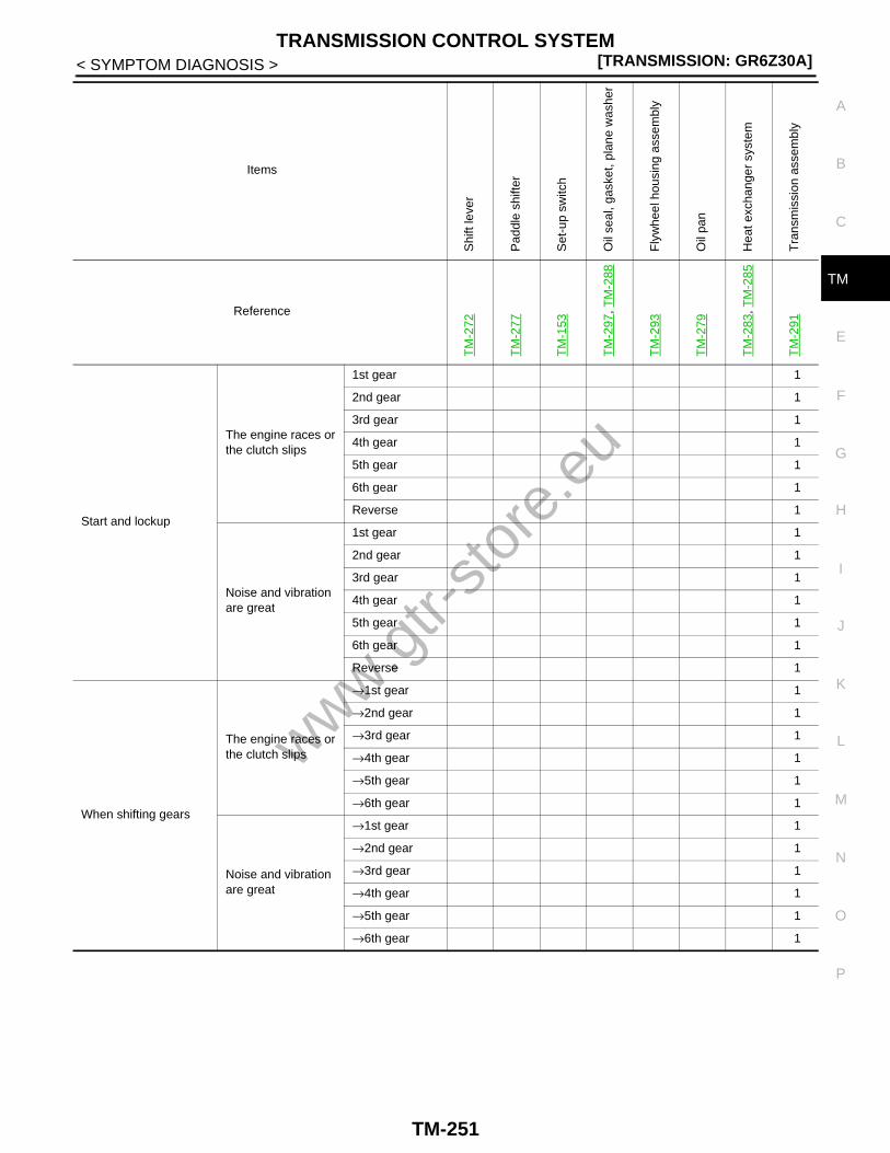
TRANSMISSION CONTROL SYSTEM[TRANSMISSION: GR6Z30A]
C
E
F
G
H
I
J
K
L
M
A
B
M
N
O
P
< SYMPTOM DIAGNOSIS >
T
Start and lockup
The engine races or the clutch slips
1st gear 1
2nd gear 1
3rd gear 1
4th gear 1
5th gear 1
6th gear 1
Reverse 1
Noise and vibration are great
1st gear 1
2nd gear 1
3rd gear 1
4th gear 1
5th gear 1
6th gear 1
Reverse 1
When shifting gears
The engine races or the clutch slips
→1st gear 1
→2nd gear 1
→3rd gear 1
→4th gear 1
→5th gear 1
→6th gear 1
Noise and vibration are great
→1st gear 1
→2nd gear 1
→3rd gear 1
→4th gear 1
→5th gear 1
→6th gear 1
Items
Shi
ft le
ver
Pad
dle
shift
er
Set
-up
switc
h
Oil
seal
, gas
ket,
plan
e w
ashe
r
Fly
whe
el h
ousi
ng a
ssem
bly
Oil
pan
Hea
t exc
hang
er s
yste
m
Tra
nsm
issi
on a
ssem
bly
Reference
TM
-272
TM
-277
TM
-153
TM
-297
, TM
-288
TM
-293
TM
-279
TM
-283
, TM
-285
TM
-291
www.gtr-
store
.eu
TM-251

[TRANSMISSION: GR6Z30A]TRANSMISSION CONTROL SYSTEM
< SYMPTOM DIAGNOSIS >
Learning error
Clutch touch pointClutch A 1
Clutch B 1
Gear position sensor
1st gear 1
2nd gear 1
3rd gear 1
4th gear 1
5th gear 1
6th gear 1
Reverse 1
The noise and vibration are generated 1 2
Oil leakage occurs 1 2 2
Shift lock error 1
Poor starting engine
Back-up lamp ON error
Items
Shi
ft le
ver
Pad
dle
shift
er
Set
-up
switc
h
Oil
seal
, gas
ket,
plan
e w
ashe
r
Fly
whe
el h
ousi
ng a
ssem
bly
Oil
pan
Hea
t exc
hang
er s
yste
m
Tra
nsm
issi
on a
ssem
bly
Reference
TM
-272
TM
-277
TM
-153
TM
-297
, TM
-288
TM
-293
TM
-279
TM
-283
, TM
-285
TM
-291
www.gtr-
store
.eu
TM-252

TRANSMISSION CONTROL SYSTEM[TRANSMISSION: GR6Z30A]
C
E
F
G
H
I
J
K
L
M
A
B
M
N
O
P
< SYMPTOM DIAGNOSIS >
T
Display/illumination er-ror
Set-up switch
R mode lamp
SNOW mode lamp
Shift position indicator
Transmission warning light
Multi-function dis-play
Gear position
A/M range
Transmission oil pressure
Transmission oil temperature
Information display
SHIFT TO THE P RANGE
CHECK POSI-TION OF SHIFT LEVER
T/M OIL TEMP HIGH DE-CREASE SPEED
T/M CLUTCH TEMP HIGH STOP VEHI-CLE UNTIL WARNING TURNS OFF
T/M SYSTEM MALFUNC-TION VISIT DEALER
T/M SYSTEM CHECK IN PROCESS
Shift leverRange change error 1
A/M range change error 1
Paddle shifterUp switch error 1
Down switch error 1
Set-up switch error 1
Shock generated at shifting is great 1 1 1 1 1 1 1 1
Items
Shi
ft le
ver
Pad
dle
shift
er
Set
-up
switc
h
Oil
seal
, gas
ket,
plan
e w
ashe
r
Fly
whe
el h
ousi
ng a
ssem
bly
Oil
pan
Hea
t exc
hang
er s
yste
m
Tra
nsm
issi
on a
ssem
bly
Reference
TM
-272
TM
-277
TM
-153
TM
-297
, TM
-288
TM
-293
TM
-279
TM
-283
, TM
-285
TM
-291
www.gtr-
store
.eu
TM-253

[TRANSMISSION: GR6Z30A]TRANSMISSION CONTROL SYSTEM
< SYMPTOM DIAGNOSIS >Main symptoms
Items Main symptoms
Shock generated at shifting is great
—Creep is great
1st gear
2nd gear
Reverse
The gear is hard to engage or the gearshift is slow(The position lamp blinks at the M range or reverse gear)
→1st gear• 1st gear is not engaged• 3rd gear is not released
→2nd gear• 2nd gear is not engaged• 4th gear is not released
→3rd gear• 3rd gear is not engaged• 1st gear is not released• 5th gear is not released
→4th gear• 4th gear is not engaged• 2nd gear is not released• 6th gear is not released
→5th gear• 5th gear is not engaged• 3rd gear is not released
→6th gear• 6th gear is not engaged• 5th gear is not released
→Reverse gear• Reverse gear is not engaged• 1st gear is not released
Start and lockup
The engine races or the clutch slips
1st gear
• Engine races• Clutch slippage
2nd gear
3rd gear
4th gear
5th gear
6th gear
Reverse
Noise and vibration are great
1st gear
Clutch judder
2nd gear
3rd gear
4th gear
5th gear
6th gear
Reverse
When shifting gears
The engine races or the clutch slips
→1st gear
—
→2nd gear
→3rd gear
→4th gear
→5th gear
→6th gear
Noise and vibration are great
→1st gear
→2nd gear
→3rd gear
→4th gear
→5th gear
→6th gear
www.gtr-
store
.eu
TM-254

TRANSMISSION CONTROL SYSTEM[TRANSMISSION: GR6Z30A]
C
E
F
G
H
I
J
K
L
M
A
B
M
N
O
P
< SYMPTOM DIAGNOSIS >
T
Learning error
Clutch touch point
Clutch AShock or slippage is generated during gear shift to 2nd, 4th, 6th gears after learning
Clutch BShock or slippage is generated during gear shift to 1st, 3rd, 5th gears after learning
Gear position sensor
1st gear The gear shift to 1st gear cannot be performed after learning
2nd gear The gear shift to 2nd gear cannot be performed after learning
3rd gear The gear shift to 3rd gear cannot be performed after learning
4th gear The gear shift to 4th gear cannot be performed after learning
5th gear The gear shift to 5th gear cannot be performed after learning
6th gear The gear shift to 6th gear cannot be performed after learning
Reverse The gear shift to reverse gear cannot be performed
The noise and vibration are generated—
Oil leakage occurs
Shift lock errorThe shift lever cannot be released from the P position after starting the engine
Poor starting engineThe starter does not operate even if the shift lever is in the P or N position
Back-up lamp ON errorThe back-up lamp does not turn on when the shift lever is se-lected to the R position
Display/illumination error
Set-up switchR mode lamp Set-up switch does not turns on/off even if the switch is op-
eratedSNOW mode lamp
Shift position indicator Shift position indicator does not illuminate
Transmission warning light
• The indicator does not illuminates and blinks even if the malfunction occurs
• The indicator illuminates and blinks even if the DTC does not occur
Multi-function display
Gear positionNot displayed
A/M range
Transmission oil pressure
• Not displayed• The value does not change even if the engine speed
changes
Transmission oil temperature
• Not displayed• The value does not change
Information display
SHIFT TO THE P RANGE
The indication does not turn off
CHECK POSI-TION OF SHIFT LEVER
T/M OIL TEMP HIGH DE-CREASE SPEED
T/M CLUTCH TEMP HIGH STOP VEHICLE UNTIL WARNING TURNS OFF
T/M SYSTEM MALFUNCTION VISIT DEALER
T/M SYSTEM CHECK IN PRO-CESS
Items Main symptoms
www.gtr-
store
.eu
TM-255

[TRANSMISSION: GR6Z30A]TRANSMISSION CONTROL SYSTEM
< SYMPTOM DIAGNOSIS >
Shift lever
Range change error The range selection cannot be performed
A/M range change errorThe A/M range change with the shift lever cannot be per-formed
Paddle shifterUp switch error The upshift is not performed at the M range
Down switch error The downshift is not performed at the M range
Set-up switch error The mode change cannot be performed
Shock generated at shifting is great Deformation, boring, clacks, oil leakage
Items Main symptoms
www.gtr-
store
.eu
TM-256

PRECAUTIONS[TRANSMISSION: GR6Z30A]
C
E
F
G
H
I
J
K
L
M
A
B
M
N
O
P
< PRECAUTION >
T
PRECAUTIONPRECAUTIONS
Precaution for Supplemental Restraint System (SRS) "AIR BAG" and "SEAT BELT PRE-TENSIONER" INFOID:0000000004110738
The Supplemental Restraint System such as “AIR BAG” and “SEAT BELT PRE-TENSIONER”, used alongwith a front seat belt, helps to reduce the risk or severity of injury to the driver and front passenger for certaintypes of collision. This system includes seat belt switch inputs and dual stage front air bag modules. The SRSsystem uses the seat belt switches to determine the front air bag deployment, and may only deploy one frontair bag, depending on the severity of a collision and whether the front occupants are belted or unbelted.Information necessary to service the system safely is included in the “SRS AIRBAG” and “SEAT BELT” of thisService Manual.WARNING:• To avoid rendering the SRS inoperative, which could increase the risk of personal injury or death in
the event of a collision which would result in air bag inflation, all maintenance must be performed byan authorized NISSAN/INFINITI dealer.
• Improper maintenance, including incorrect removal and installation of the SRS, can lead to personalinjury caused by unintentional activation of the system. For removal of Spiral Cable and Air BagModule, see the “SRS AIRBAG”.
• Never use electrical test equipment on any circuit related to the SRS unless instructed to in this Ser-vice Manual. SRS wiring harnesses can be identified by yellow and/or orange harnesses or harnessconnectors.
Aluminum Die-Casting Parts Handling INFOID:0000000004110737
PROHIBITION OF WELDING OR BEATING REPAIR• Material made of aluminum die-casting parts is heat-treated and looses strength when being exposed to
welding heat. Do not perform welding repair for cracks, damage or others.• For aluminum die-casting parts deformation, do not perform repair by beating. Always repair by replacement
as an assembly.
CRACK CHECKWhen the vehicle is damaged, always perform a visual deformation check and a crack check.
Crack Check ProceduresFor a crack check, use dye penetrant inspection fluid (pre-cleaning fluid, penetrant fluid and developer fluid).CAUTION:Always perform a crack check in accordance with the procedures specified by the manufacturer of thedye penetrant inspection fluid.1. Spray pre-cleaning fluid on the checking surface for cleaning.2. Spray penetrant fluid on the checking surface and wait until the penetrant fluid soaks into any cracks.3. Wipe off excessive penetrant fluid, and then also lightly wipe off penetrant fluid using a wet cloth.4. Spray developer fluid on the checking surface.5. Cracks, if any, are dyed red in color.
STRAY CURRENT CORROSION• Corrosion occurs to aluminum die-casting parts by the stray current corrosion phenomenon, when directly
contacting other parts made of steel. Always apply anti-stray current corrosion paint (primer) on the mount-ing surface.
• Clean mounting surface to prevent any foreign matter, steel powder or others from being mixed in. Alwaysapply the specified adhesive when installing.
• Corrosion by stray current corrosion may occur when installing with any other bolts than the specified bolt.Always use the specified bolt that is surface treated.
• When loosening the specified bolt that is tightened, the treated surface may peel. Never reuse the specifiedbolt that is tightened once.
TIGHTENING TORQUE CONTROL
www.gtr-
store
.eu
TM-257

[TRANSMISSION: GR6Z30A]PRECAUTIONS
< PRECAUTION >Material made of aluminum die-casting parts is soft in term of hardness. Tightening torque must be controlledexactly as specified. Always use a torque wrench to install any part to the specified tightening torque.WARNING:Never use a power tool to remove or tighten bolts for aluminum die-casting part.
General Precautions INFOID:0000000004020011
• Use “Genuine NISSAN Transmission oil R35 special”.• Work in a clean workplace.• Avoid using cotton gloves or a waste cloth to prevent the entry of lint. Use paper towel.• Check for the correct status prior to removal and installation, disassembly and assembly.• Use genuine NISSAN parts for replacement.• Do not drop foreign matter into the transmission assembly inside.• Check for damage, breakage and twist when replacing the O-ring and gaskets, etc.• Check that no dirt is present on the mounting area when installing the parts.• Check that tools and shop waste cloths are not left after finishing service work.• Check and replace the oil level with the vehicle in a horizontal position.• Do not reuse drained transmission oil.• Treat the replaced transmission oil and cleaning oil as waste oil.
Precautions for Replacement of TCM and Transmission Assembly INFOID:0000000004020012
Perform the following learning when the TCM and transmission assembly are replaced.
CLUTCH LEARNINGThe transmission applies the standby pressure to clutch A or clutch B after a gear is engaged to reduce theclutch clearance in order to speed up the response to start-up or gear shift. The stand-by pressure is notproper after replacing the TCM and transmission assembly. It is necessary for TCM to learn it.
GEAR LEARNINGThe engaged gear position has variations per unit. It is necessary for TCM to learn it after replacing the TCMand transmission assembly.• Refer to TM-8, "TCM REPLACEMENT : Description" when replacing the TCM.• Refer to TM-9, "TRANSMISSION ASSEMBLY REPLACEMENT : Description" when replacing the transmis-
sion assembly.
Precautions Before Performing Diagnosis INFOID:0000000004020013
Check the following items before performing the diagnosis. Be careful that the applicable item may not alwaysbe malfunctioning.
PRECAUTION FOR MECHANISM
Mechanism Symptom Use conditions and constraint conditions
Manual transmission base
If the temperature is high just after sport driving, for exam-ple, a rattle or other noise may be heard at idle or driving at a slow speed, because there is less friction.
When the temperature is lowered, the noise is reduced.
A click noise may be heard during a gear shift. —
www.gtr-
store
.eu
TM-258

PRECAUTIONS[TRANSMISSION: GR6Z30A]
C
E
F
G
H
I
J
K
L
M
A
B
M
N
O
P
< PRECAUTION >
T
PRECAUTIONS FOR SYMPTOM
Wet-type multi-plate clutch
With the vehicle stationary and the shift lever in the A ⇔ M, or R range, when the brake pedal is released, the ve-hicle enters the status just like partial engagement of clutch in vehicles with manual transmission to prepare for start-up, and starts moving slowly (or in some circum-stances, it may not start at all).
Securely depress the brake pedal while the vehicle is stopped.
If the brake pedal and accelerator pedal are depressed to-gether, under some conditions, the engine may stall or the clutch may overheat, resulting in damage in the transmis-sion.
Therefore, never depress the brake pedal and accelerator pedal together.
If “starting the vehicle in 2nd gear of M range” or “stop by depressing adjustment of the accelerator pedal on a slope using every gear position” is performed, the clutch over-heats just like vehicles with manual transmission, resulting in damage in the transmission or engine stall.
• Start the vehicle in 1st gear. • Starting the vehicle in 2nd gear of the M
range is restricted to when starting the vehicle with restrained drive power on an extremely slippery road such as a snowy road.
• When stopping on a slope, depress the brake pedal and do not perform a stop-ping operation by depressing adjustment of the accelerator pedal.
Electronically controlled hy-draulic control
The following symptoms may occur by oil viscosity restric-tion variations due to temperature change.1. A slippage feeling or shock may occur during start-
up and gear shift.2. At very low temperatures in winter, the system check
time may be prolonged by oil pressure response characteristic variations.
1. After the normal temperature is re-sumed, the slippage feeling and shock is reduced.
2. During the system check, the shift le-ver cannot be moved out from the P position. Therefore, operate the shift lever only after the system check indi-cator turns off. In addition, operation noise like a clank may be heard or the engine speed may drop during the system check, but they are not mal-function.
Mode change
In the M range, as the gear shift speed is increased, a shock or jerky feeling may be felt during start-up and gear shift.
—
Because R mode of the M range is designed to increase the shift change speed during sport driving, when driving at low vehicle speed and low engine speed, the shift change time may be rather prolonged.
—
Rear final drive (mechanical LSD) and transfer (E-TS)
Turning with a large steering wheel angle at low tempera-ture increases LSD effect because of high oil viscosity, vi-brations or operation noise caused by tire slippage may occur.
When straight-ahead driving is resumed or the oil temperature increases, the vibrations and operation noise are reduced.
Lightweight flywheel
Because of the engine speed variations due to the air con-ditioner operation, a rattle or other noise may be heard at idle or driving at a slow speed.
—
At the engine start or stop, a rattle may be heard. —
Mechanism Symptom Use conditions and constraint conditions
www.gtr-
store
.eu
TM-259

[TRANSMISSION: GR6Z30A]PRECAUTIONS
< PRECAUTION >
Symptom Cause Action
When or after the engine starts
The shift lever is not released from the P range.
The system performs the system check of transmission after the engine starts. There-fore, the shift lever is not released from the P range by shift lock even if the driver de-presses the brake during the check. This is normal. The system check time may be pro-longed at low oil temperature.
Wait until the system check finishes.
The vehicle cannot be driven after starting the engine at the N range.
When the engine starts at the N range after the engine stops at the driving range (A/M or R range), the vehicle may not start for safety. This is normal.• Conditions that the vehicle cannot be
driven- The engine starts at the N range after
stopping at the A/M range, and the R range is selected
- The engine starts at the N range after stopping at the R range, and the A/M range is selected
If the engine starts at the N range, the vehicle can be driven by selecting the desired driving range after selecting the P range once. Perform the engine stop or start at the P range for safety reasons.
The gear shift takes time at low oil temper-ature.
The oil viscosity is high and the oil flow re-striction is large at low oil temperature, and the oil pressure response takes time.
Smooth gear shift is re-sumed, when the oil temperature increases.
The engine speed fluctuates when the shift lever shifts from the N range or P range to the driving range (A/M, R range) without the brake pedal depressed.
If the shift lever shifts to the driving range (A/M or R range) without the brake pedal depressed, the clutch becomes the partial clutch engagement status simultaneously with the gear engagement. Therefore, the engine load changes. As a result, the en-gine speed may vary or decrease.
Securely depress the brake before shifting the shift lever to the driving range (A/M, R range) for safety reasons.
The vehicle cannot start at any gears higher than 3rd gear.
The gear position that the vehicle can start is only 1st, 2nd, and reverse gears. The ve-hicle cannot start at any gears higher than 3rd gear because the load for the clutch is too great.
Start the vehicle in 1st or reverse gear. On a slip-pery road, use SNOW mode of the A range. Start the vehicle in 2nd gear only when you want to start with re-strained drive power es-pecially on a slippery road.
The gear shift is not performed or slow.
No manual upshift is accepted during start-up.
The manual shift change is inhibited in or-der to reduce the load to the clutch during start-up (until the clutch is engaged).
Shift the gear only after the start-up is finished (after the clutch is en-gaged).
A downshift to 1st gear is not accepted dur-ing starting in 2nd gear.
For the purpose of safety and clutch protec-tion, a downshift to 1st gear is not accepted during start-up and when the accelerator pedal is depressed.
Stop the vehicle to shift down to 1st gear or se-lect the A range to enter the automatic shift. Also start the vehicle in 1st gear.
The gear shift takes time at low oil temper-ature.
The oil viscosity is high and the oil flow re-striction is large at low oil temperature, and the oil pressure response takes time.
Smooth gear shift is re-sumed when the oil tem-perature increases.
The gear shift is not performed even if the paddle shifter operation is performed.
• The paddle shifter operation can be per-formed only in the M range.
• If the engine over revving occurs or the specified engine speed is not reached af-ter a gear shift, the gear shift is inhibited, and the shift position indicator on the combination meter blinks to warn the driver.
Use the M range and perform gear shift at the proper engine speed.
www.gtr-
store
.eu
TM-260

PRECAUTIONS[TRANSMISSION: GR6Z30A]
C
E
F
G
H
I
J
K
L
M
A
B
M
N
O
P
< PRECAUTION >
T
The gear shift is not performed or slow.
The continuous manual shift is not accept-ed.
The excessively fast continuous gear shift is prohibited for safety reasons. The gear shift that can be accepted during the gear shift is only the next gear shift.
Take interval time to continuously operate the paddle shifter.
The downshift is not accepted at stall in 2nd gear (under conditions that the vehicle is stopped with the accelerator pedal and brake pedal depressed simultaneously and the vehicle is stopped on a slope with the accelerator pedal depressed).
The downshift is not accepted at stall for safety reasons.
The stall is prohibited. The downshift is accept-ed by stopping the vehi-cle with the accelerator pedal released.
The gear shift in R mode of the M range is slow.
The predictive pre-shift control provides a waiting gear selection focusing on the full sport driving. Therefore in normal driving, it takes time for changing the waiting gear and the gear shift time may be prolonged.
R mode of the M range is basically used in sport driving.
No automatic upshift occurs in R mode of the M range.
In order to provide the operation feeling of manual transmission, no automatic upshift occurs like manual transmission.
Upshift manually or use in Normal mode of the M range.
In Normal mode of M range, 2 speed gear shift is performed for one manual upshift.
Normal mode of M range performs the au-tomatic upshift when the specified engine speed is reached. During the automatic up-shift, if a manual upshift intervenes by the paddle shifter, a total of a 2-speed gear shift (1-speed automatic gear shift + 1-speed manual gear shift) is performed.
If the automatic upshift is used or a manual gear shift is done a little earli-er, 1-speed gear shift can be attained. Or, R mode of the M range without automatic up-shift is used.
While driving in the A range, after the vehi-cle is accelerated for merging onto a free-way, for example, the automatic upshift does not occur soon after the accelerator pedal is released.
When the vehicle is accelerated rather hard for merging onto a freeway, or runs on a ramp curve with side G applied, the adap-tive shift control works to activate the gear hold status in which no gear shift occurs for a certain period of time. This symptom stays longer in R mode than Normal mode.
Waiting for a certain pe-riod of time deactivates the gear hold status. Or upshift manually.
During a sudden deceleration, no automatic downshift occurs.
During a sudden deceleration, if a tire lock occurs, the actual vehicle speed cannot be judged (the vehicle body moves, but the wheels stop), therefore the appropriate gear can no longer be selected. For safety reasons, a gear shift is inhibited.
With a certain period of time after the tire lock disappears, an automat-ic gear shift to the ap-propriate gear is resumed.
An upshift near the engine rev limit causes a drop of the drive power.
A manual upshift near the engine rev limit may activate the engine over-rev protection depending on the timing and lower the en-gine torque. Therefore, an upshift at this timing drops the drive power.
This symptom can be eliminated by upshifting a little earlier.
Shock generated by gearshift is great.
Shift shock varies depending on how the accelerator pedal depressed during a gear shift. Because the tuning allows an increase of the shift speed as the accelerator pedal travel increases, the shift shock also in-creases.For example, start the vehicle with the ac-celerator pedal fully depressed, as the vehi-cle speed increases, shift up to 2nd gear, after that release the accelerator pedal and shift up to 3rd gear. In this case, compared to 2nd to 3rd shift shock, 1st to 2nd shift shock feels larger.
To prevent shift shock, drive with gentle accel-erator operation.
Symptom Cause Action
www.gtr-
store
.eu
TM-261

[TRANSMISSION: GR6Z30A]PRECAUTIONS
< PRECAUTION >
The drive pow-er is not gener-ated or weak, or the engine races.
The drive power is weak when the temper-ature becomes extremely cold. The engine does not race.
The engine torque and engine speed are restricted to protect the transmission and engine at low temperature (the transmis-sion oil temperature is approximately −20°C (−4°F) or less, or the engine oil temperature is approximately 0°C (32°F) or less). The drive power becomes weak or the engine speed does not increase over the specified speed.
If the oil temperature ris-es, the restriction of en-gine torque and engine speed is cancelled.
The drive power is not generated at high oil temperature. The engine does not race.
The engine torque and engine speed are restricted to protect the transmission and engine at high temperature (the transmis-sion oil temperature is approximately 150°C (302°F) or more, or the engine oil tempera-ture is approximately 135°C (275°F) or more). The drive power becomes weak or the engine speed does not increase over the specified speed.
Reduce the speed or stop the vehicle in a safe place until the engine oil temperature decreases or the transmission warning lamp turns off.
The drive power is not generated at high clutch temperature.
The engine torque and engine speed are restricted to protect the clutch at high clutch temperature. The drive power is not trans-mitted when the temperature is further in-creased. At this time, the vehicle may move if the brake pedal is not depressed on a slope.
Reduce the speed or stop the vehicle with the brake pedal depressed until the transmission warning lamp turns off.
At very low temperature, hard acceleration causes engine racing.
At low oil temperature, because of a high oil viscosity, oil pressure response takes time. Therefore, before the clutch is engaged, the engine speed increases, which may cause an engine racing.
Do not perform hard ac-celeration at low outside temperature with cold transmission.
After the vehicle stops with a sudden decel-eration, depressing the accelerator pedal causes engine racing.
Under a sudden deceleration, tire lock eas-ily occurs. To prevent an engine stall when a lock occurs, the clutch is released. Under that status, depressing the accelerator ped-al may cause racing.
With a certain period of time after releasing the accelerator pedal, the clutch is engaged and the racing stops.
The engine stalls.
If the accelerator pedal and brake pedal are depressed together to stop, the engine stalls.
Because the clutch engagement pattern is adjusted for start-up or acceleration de-pending on the accelerator pedal operation, if the brake pedal is depressed together, a force to stop the engine is generated by braking force and the engine may stall.
Do not depress the ac-celerator pedal and brake pedal together.
The set-up switch cannot be changed.
It cannot be changed from SNOW mode to R mode.
The mode changes by 1 step per 1 mode switch operation.
When changing from SNOW mode to R mode, set to Normal mode once, and then press and hold the switch for 1 second to select R mode.
It cannot be changed from R mode to SNOW mode.
When changing from R mode to SNOW mode, set to Normal mode once, and then press and hold the switch for 1 second to select SNOW mode.
The combina-tion meter dis-play is malfunctioning.
The oil change history is reset without oper-ation.
The oil change history is reset if the power supply is cut off when the battery is re-moved at the battery replacement.
Note the history before removing the battery. Perform manual setting of history after recon-necting.
Symptom Cause Action
www.gtr-
store
.eu
TM-262

PREPARATION[TRANSMISSION: GR6Z30A]
C
E
F
G
H
I
J
K
L
M
A
B
M
N
O
P
< PREPARATION >
T
PREPARATIONPREPARATION
Special Service Tools (GT-R certified NISSAN dealer) INFOID:0000000004020014
Commercial Service Tools (GT-R certified NISSAN dealer) INFOID:0000000004110758
Tool number(Kent-Moore number)Tool name
Description
KV381054S0(J-34286)Puller
Removing the front oil seal
ST30720000(J-25405)Drifta: 77 mm (3.03 in) dia.b: 55.5 mm (2.185 in) dia.
Installing front oil seal
KV40104830( — )Drifta: 70 mm (2.76 in) dia.b: 63.5 mm (2.500) dia.
Installing front oil seal
ZZA0601D
ZZA0811D
ZZA1003D
Tool name Description
Power tool Loosening bolts and nuts
PBIC0190E
www.gtr-
store
.eu
TM-263
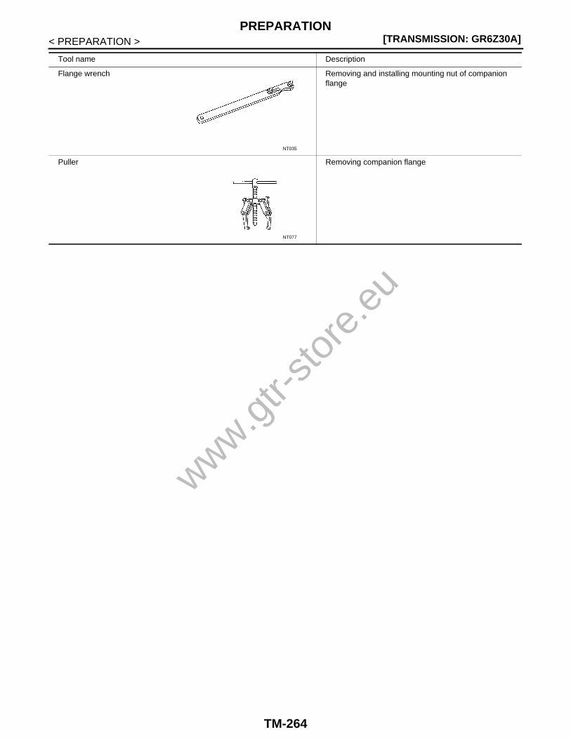
[TRANSMISSION: GR6Z30A]PREPARATION
< PREPARATION >
Flange wrench Removing and installing mounting nut of companion flange
Puller Removing companion flange
Tool name Description
NT035
NT077
www.gtr-
store
.eu
TM-264

TRANSMISSION OIL[TRANSMISSION: GR6Z30A]
C
E
F
G
H
I
J
K
L
M
A
B
M
N
O
P
< ON-VEHICLE MAINTENANCE >
T
ON-VEHICLE MAINTENANCETRANSMISSION OIL
Inspection INFOID:0000000004020015
LEAKAGE CHECKVisually check transmission assembly surrounding area (oil seal, drain plug, filler plug, transmission case,etc.) for smears and leakage of transmission oil.
• *1: When the oil does not drop
• *2: When the oil drops
CONDITION CHECKRemove the filler plug, insert a finger into the filler hole, and judge the oil conditions from the transmission oilapplied to the inside of the transmission case.CAUTION: Be careful not to cut the finger with edges.
Oil smears/leakage status from transmission assembly Required operation Reference
Smears*1 Smears from each part on the transmission assemblyUse part cleaner or the equivalent to wipe out smeared oil. Then, check for oil leakage.
—
Leakage*2
Mating surface between oil pan and caseCheck the seal surface condition. Replace the oil pan gasket only if there is a non-standard condi-tion. Check for oil leakage.
TM-279
Park position switch mounting surfaceCheck the mounting surface condition. Replace the plain washer only if there isn’t any other mal-functioning condition. Check for oil leakage.
TM-281
Heat exchanger & bracket mounting surface and heat exchanger mounting bolt
Check the seal surface condition. Replace the O-ring at the location where the oil leakage occurred if there isn’t any other malfunctioning condition. Check for oil leakage.
TM-285
Front oil seal
Check the oil seal mounting surface and sliding surface condition. Replace the front oil seal only if there isn’t any other malfunctioning condition. Check for oil leakage.
TM-288
Drain plug Replace the drain plug. Check for oil leakage. TM-279
Filler plugReplace the filler plug gasket. Check for oil leak-age.
TM-297
Transmission harness connector Replace the transmission assembly. TM-291
• 3rd-5th check pin• Idler bolt• Plug
Replace the plain washer or O-ring. Check for oil leakage.
TM-297
Transmission oil status Possible cause Required operation
Varnish-like condition (It is as thick as varnish).
Clutch is burned.Change the transmission oil. Check the trans-mission assembly or any other parts on the ve-hicle.
Milky or cloudy
Water is mixed in the fluid.Example: • Inflow of engine coolant by internal explo-
sion of heat exchanger• Inflow of water from breather by flood, etc.
Change the transmission oil. Check for flooded area.
A large amount of metal particles are contained in the fluid.
Sliding portions in the transmission assembly are excessively worn.
Change the transmission oil. Check the trans-mission assembly operation for any malfunc-tioning condition.
www.gtr-
store
.eu
TM-265

[TRANSMISSION: GR6Z30A]TRANSMISSION OIL
< ON-VEHICLE MAINTENANCE >
Draining INFOID:0000000004020016
1. Remove the front diffuser. Refer to XX-XX, "*****".2. Remove the heat insulator.
3. Remove the filler plug ( ).
4. Remove the drain plug (1) and drain tube (2) from the oil pan,and then drain the transmission oil.
5. Install the drain tube to the oil pan. Refer to TM-279, "ExplodedView".
Filling INFOID:0000000004020017
REPLACEMENT/ADJUSTMENT PROCEDURENOTE:Replace the filler plug gasket and drain plug with new ones after oil level adjustment.1. Remove the filler plug ( ) and drain plug, and then fill with the
transmission oil until it leaks from the drain hole.
CAUTION:• Always use the specified transmission oil. In addition,
always use the filler after cleaning. If use/mixed use/mis-use of the transmission oil other than the specified brandoccurs, the original performance cannot be obtained or itmay cause serious malfunctions.
• Check that dust does not mix.• Always use paper towels. Never use waste cloth.
2. Install the filler plug and drain plug. Refer to TM-291, "Exploded View (GT-R certified NISSAN dealer)"(filler plug), TM-279, "Exploded View" (drain plug).
3. Start the engine and select the M range.4. With depressing the brake pedal, shift the paddle shifter to the N range → M range, 1st gear (wait for 5
seconds) → M range, 2nd gear (wait for 5 seconds) → M range, 1st gear → N range at idle.5. Stop the engine.6. Remove the filler plug and drain plug, and then fill with the transmission oil until it leaks from the drain
hole.7. Install the filler plug and drain plug. Refer to TM-291, "Exploded View (GT-R certified NISSAN dealer)"
(filler plug), TM-279, "Exploded View" (drain plug).8. Install the heat insulator.
NNDIA0018ZZ
NNDIA0033ZZ
Transmission oil : Refer to TM-299, "General Specification".
NNDIA0018ZZ
www.gtr-
store
.eu
TM-266

TRANSMISSION OIL[TRANSMISSION: GR6Z30A]
C
E
F
G
H
I
J
K
L
M
A
B
M
N
O
P
< ON-VEHICLE MAINTENANCE >
T
9. Start the engine and run it at idle. Run the engine until the oil temperature reaches 50°C (122°F) whilechecking FLUID TEMP in “DATA MONITOR” of CONSULT-III.
10. With depressing the brake pedal, shift the paddle shifter to the N range → M range, 1st gear (wait for 5seconds) → M range, 2nd gear (wait for 5 seconds) → M range, 1st gear → N range at idle.
11. Stop the engine and wait for 5 minutes.12. Remove the drain plug. Install the drain plug when the transmission oil begins to drip (1 drop/1 second).
Refer to TM-279, "Exploded View".CAUTION:• Perform from step 11 to step 12 within 25 minutes.• Repeat the procedure from step 6 if the transmission oil does not leak from the drain hole.• Never reuse drain plug.
13. Replace the filler plug gasket with new ones.CAUTION:Never reuse filler plug gasket.
14. Install the front diffuser. Refer to XX-XX, "*****".
REFILL ADJUSTMENT PROCEDURENOTE:Replace the filler plug gasket and drain plug with new ones after oil level adjustment.1. Remove the front diffuser. Refer to XX-XX, "*****".2. Remove the heat insulator.3. Start the engine and select the M range.4. With depressing the brake pedal, shift the paddle shifter to the N range → M range, 1st gear (wait for 5
seconds) → M range, 2nd gear (wait for 5 seconds) → M range, 1st gear → N range at idle.5. Stop the engine.6. Remove the filler plug ( ) and drain plug, and then fill with the
transmission oil until it leaks from the drain hole.
CAUTION:• Always use the specified transmission oil. In addition,
always use the filler after cleaning. If use/mixed use/mis-use of non-specified transmission oil other than the spec-ified brand occurs, the original performance cannot beobtained or it may cause serious malfunctions.
• Check that dust does not mix.• Always use paper towels. Never use waste cloth.
7. Install the filler plug and drain plug. Refer to TM-291, "Exploded View (GT-R certified NISSAN dealer)"(filler plug), TM-279, "Exploded View" (drain plug).
8. Install the heat insulator.9. Start the engine and run it at idle. Run the engine until the oil temperature reaches 50°C (122°F) while
checking FLUID TEMP in “DATA MONITOR” of CONSULT-III.10. With depressing the brake pedal, shift the paddle shifter to the N range → M range, 1st gear (wait for 5
seconds) → M range, 2nd gear (wait for 5 seconds) → M range, 1st gear → N range at idle.11. Stop the engine and wait for 5 minutes.12. Remove the drain plug. Install the drain plug when the transmission oil begins to drip the drop status (1
drop/1 second). Refer to TM-279, "Exploded View".CAUTION:• Perform from step 11 to step 12 within 25 minutes.• Repeat the procedure from step 6 if the transmission oil does not leak from the drain hole.• Never reuse drain plug.
13. Replace the filler plug gasket with new ones.CAUTION:Never reuse filler plug gasket.
14. Install the front diffuser. Refer to XX-XX, "*****".
Transmission oil : Refer to TM-299, "General Specification".
NNDIA0018ZZ
www.gtr-
store
.eu
TM-267

[TRANSMISSION: GR6Z30A]SHIFT POSITION
< ON-VEHICLE MAINTENANCE >
SHIFT POSITION
Inspection and Adjustment INFOID:0000000004020018
INSPECTION1. Turn the ignition switch to ON at the shift lever P position.2. The shift lever can shift from the P position to the R position when the brake pedal is depressed. Alterna-
tively, the shift lever cannot shift from the P position to the R position without the brake pedal depressed.3. Operate the shift lever and check for excessive effort, sticking, noise or rattle.4. When the shift lever is operated, a click is felt, and the fixed position is correct and corresponds to the shift
position indicator in the combination meter5. Check that the shift lever is shifted through all the shift positions
in the manner shown in the figure.
6. Check in the P and N positions that the knob button can beoperated without sticking when the button is pressed without theshift lever pressed forward and backward.
7. Check that in the R position the shift lever can be operated with-out sticking when the shift lever is operated left and right.
8. The back-up lamp can turn on and the reverse warning buzzer can sound with the shift lever in the R posi-tion only.
9. Check that the engine can be started with the shift lever in the P and N positions only.10. The transmission is completely locked with the shift lever in the P position.11. The shift position indicator of combination meter should change to the A range display or M range display
when the shift lever is operated to the M position.12. The shift position indicator in the combination meter should not change when each load of 30 N (3.1 kg) is
applied (pressed) to front and rear side at the shift lever in the P position, front side at the shift lever in theR position, front side at the shift lever in the N position and rear side at the shift lever in the A position.
ADJUSTMENT1. Disconnect the control cable from the control device assembly. Refer to TM-275, "Exploded View (GT-R
certified NISSAN dealer)".2. Shift the parking lever of transmission assembly to the P range
(A).
3. Rotate the wheels at least a quarter turn and the Park positionmechanism is fully engaged.
4. Shift the shift lever to the P position.5. Install the socket of the control cable to the control device
assembly, and fix them with lock plate.6. Insert the I-end bolt into the cable lever of the control device
assembly, and apply the load of 9.8 N (1 kg) in the cable lever Pdirection (toward vehicle front) to the control cable.
7. Release the control cable and temporarily tighten the lock nut. Then, tighten the lock nut to the specifiedtorque. Refer to TM-275, "Exploded View (GT-R certified NISSAN dealer)".
A : Depress the brake pedal. Press and operate the knob button.
B : Press and operate the knob button.
C : Operate without condition.
D : Automatic return.
NNDIA0020JP
B : Other than P position
NNDIA0011ZZ
www.gtr-
store
.eu
TM-268

FLY WHEEL HOUSING ASSEMBLY[TRANSMISSION: GR6Z30A]
C
E
F
G
H
I
J
K
L
M
A
B
M
N
O
P
< ON-VEHICLE MAINTENANCE >
T
FLY WHEEL HOUSING ASSEMBLY
Inspection (GT-R certified NISSAN dealer) INFOID:0000000004020019
DESCRIPTIONCheck the flywheel housing assembly if the following symptom occurs on the vehicle. Replace the flywheelhousing assembly if any malfunctioning condition is detected.• Noise from floor lower side• Vibration from floor lower side or whole vehicle
INSPECTION PROCEDUREMove the main propeller shaft upward/downward by hand to check the companion flange of the flywheel hous-ing assembly for looseness. Measure the looseness of companion flange if there is any looseness.
Looseness (radial play) measurement of companion flange
1. Separate the main propeller shaft. Refer to XX-XX, "*****".2. Fix the dial gauge to the companion flange of the flywheel hous-
ing assembly, and then measure the looseness of companionflange by moving the companion flange upward/downward.
3. Replace the flywheel housing assembly if the looseness of thecompanion flange exceeds the standard. Refer to TM-293,"Exploded View (GT-R certified NISSAN dealer)".
A : Measuring point
Radial playStandard : Refer to TM-300, "Flywheel Housing As-
sembly (GT-R certified NISSAN dealer)".
NNDIA0135ZZwww.gtr-
store
.eu
TM-269

[TRANSMISSION: GR6Z30A]TCM
< ON-VEHICLE REPAIR >
ON-VEHICLE REPAIRTCM
Exploded View (GT-R certified NISSAN dealer) INFOID:0000000004020020
CAUTION:• Before TCM is replaced, the IP characteristics must be extracted, based on the information read out
from the malfunctioning TCM. For acquiring the IP characteristic data, refer to “CONSULT-III GT-RTCM CONFIGURATION MANUAL”.
• If no IP characteristic data can be extracted, TCM and the transmission assembly must be replacedas a set.
Removal and Installation (GT-R certified NISSAN dealer) INFOID:0000000004020021
REMOVALCAUTION:• Before TCM is replaced, the IP characteristics must be extracted, based on the information read out
from the malfunctioning TCM. For acquiring the IP characteristic data, refer to “CONSULT-III GT-RTCM CONFIGURATION MANUAL”.
• If no IP characteristic data can be extracted, TCM and the transmission assembly must be replacedas a set.
1. Disconnect battery cable from negative terminal.2. Remove the trunk front finisher. Refer to XX-XX, "*****".3. Disconnect the TCM harness connector with the following procedure.
• Push the protrusion for fixing and fully open the levers (A) asshown in the figure when disconnecting and connecting theTCM harness connector.
4. Remove the TCM mounting bolt.5. Remove the TCM from the vehicle.
1. TCM
Refer to XX-XX, "*****" in GI section for the symbols shown in the figure.
NNDIA0013GB
1 : TCM
Direction B : Disconnect
Direction C : Connect
NNDIA0021ZZ
www.gtr-
store
.eu
TM-270
TCM[TRANSMISSION: GR6Z30A]
C
E
F
G
H
I
J
K
L
M
A
B
M
N
O
P
< ON-VEHICLE REPAIR >
T
INSTALLATIONNote the following, and install in the reverse order of removal.CAUTION:Refer to TM-258, "Precautions for Replacement of TCM and Transmission Assembly" when the TCM isreplaced.
www.gtr-
store
.eu
TM-271
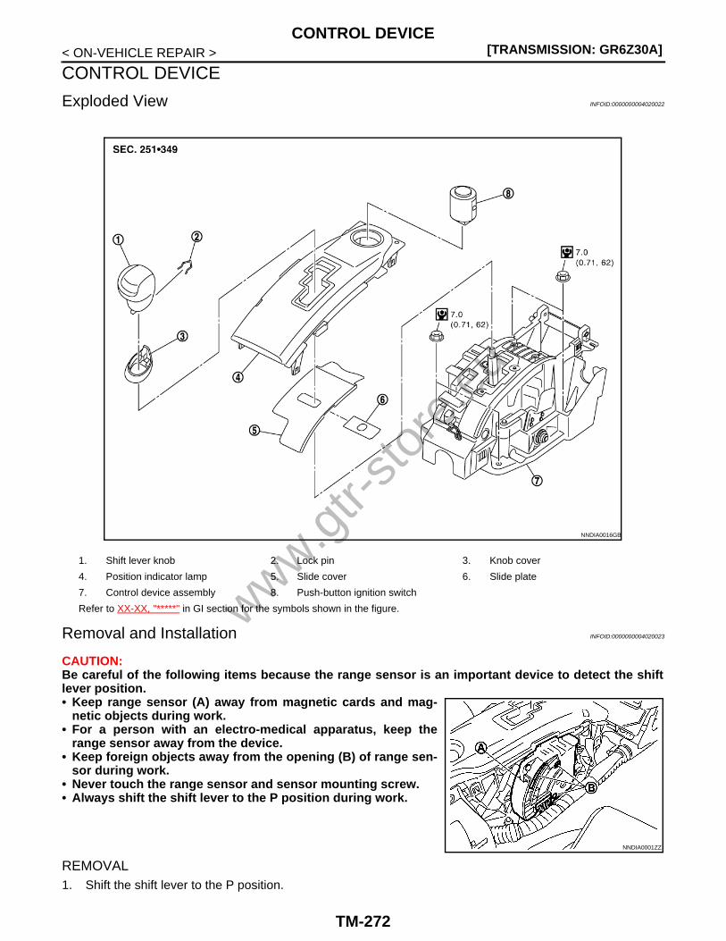
[TRANSMISSION: GR6Z30A]CONTROL DEVICE
< ON-VEHICLE REPAIR >
CONTROL DEVICE
Exploded View INFOID:0000000004020022
Removal and Installation INFOID:0000000004020023
CAUTION:Be careful of the following items because the range sensor is an important device to detect the shiftlever position.• Keep range sensor (A) away from magnetic cards and mag-
netic objects during work.• For a person with an electro-medical apparatus, keep the
range sensor away from the device.• Keep foreign objects away from the opening (B) of range sen-
sor during work.• Never touch the range sensor and sensor mounting screw.• Always shift the shift lever to the P position during work.
REMOVAL1. Shift the shift lever to the P position.
1. Shift lever knob 2. Lock pin 3. Knob cover
4. Position indicator lamp 5. Slide cover 6. Slide plate
7. Control device assembly 8. Push-button ignition switch
Refer to XX-XX, "*****" in GI section for the symbols shown in the figure.
NNDIA0016GB
NNDIA0001ZZ
www.gtr-
store
.eu
TM-272

CONTROL DEVICE[TRANSMISSION: GR6Z30A]
C
E
F
G
H
I
J
K
L
M
A
B
M
N
O
P
< ON-VEHICLE REPAIR >
T
2. Lower the rear side of the knob cover (1) downward.3. Pull out the lock pin (2) from the shift lever knob (3).4. Remove the shift lever knob and the knob cover.5. Remove the console finisher assembly, instrument side panel
LH/RH, and center console assembly. Refer to XX-XX, "*****".6. Disconnect the control cable from the control device assembly.
Refer to TM-275, "Exploded View (GT-R certified NISSANdealer)".
7. Disconnect the push-button ignition switch connector and therange sensor connector, and remove the harness clip.
8. Remove the control device assembly mounting bolt.9. Remove the control device assembly from the vehicle.
CAUTION:Never place the control device assembly upside-down after removal. In addition, never place therange sensor side down.
INSTALLATIONNote the following, and install in the reverse order of removal.• Refer to “ADJUSTMENT” in TM-268, "Inspection and Adjustment" when installing the control cable to the
control device assembly.• Note the following items when installing the shift lever knob.1. Install the lock pin (1) to the shift lever knob (2).2. Install the knob cover (3) to the shift lever knob.3. Insert the shift lever knob into the shift lever until it clicks.
Disassembly and Assembly INFOID:0000000004020024
DISASSEMBLYCAUTION:Always shift the shift lever in the N position when performing disassembly and assembly of controldevice assembly.1. Press the shift lock release button, and then shift the shift lever in the N position.2. Insert a screwdriver into tabs (A: 4 locations), and remove the
position indicator plate (1) from the control device assembly (2)while lifting it up.CAUTION:The tabs crack easily. Be careful when removing.
3. Remove the starter switch from the position indicator plate.4. Remove the slide cover from the control device assembly.
AssemblyNote the following, and assemble in the reverse order of disassembly.• Align the convex area (A) of slide cover (1) with the convex area (B) of control device assembly (2) as shown
in the figure, and then install the position indicator plate. Check the shift lever movement after installation.Assemble again if any malfunctioning condition is detected.
NNDIA0126ZZ
NNDIA0127ZZ
NNDIA0128ZZ
www.gtr-
store
.eu
TM-273

[TRANSMISSION: GR6Z30A]CONTROL DEVICE
< ON-VEHICLE REPAIR >
Inspection INFOID:0000000004020025
INSPECTION AFTER INSTALLATIONCheck the shift position after installation. Adjust the shift position if any malfunctioning condition is detected.Refer to TM-268, "Inspection and Adjustment".
NNDIA0002ZZ
www.gtr-
store
.eu
TM-274

CONTROL CABLE[TRANSMISSION: GR6Z30A]
C
E
F
G
H
I
J
K
L
M
A
B
M
N
O
P
< ON-VEHICLE REPAIR >
T
CONTROL CABLE
Exploded View (GT-R certified NISSAN dealer) INFOID:0000000004020026
Removal and Installation (GT-R certified NISSAN dealer) INFOID:0000000004020027
CAUTION:• Never twist the control cable.• Never bend the control cable excessively. (Maintain a winding radius of 200 mm (7.87 in) dia. or
more.)
1. Lock plate 2. Control device assembly 3. Control cable
4. Bracket A 5. Transmission assembly 6. Bracket B
7. Plain washer 8. Lock pin
A. Retainer
: Apply multi-purpose grease or equivalent
Refer to XX-XX, "*****" in GI section for the symbols other than above.
NNDIA0010GB
www.gtr-
store
.eu
TM-275

[TRANSMISSION: GR6Z30A]CONTROL CABLE
< ON-VEHICLE REPAIR >• Never damage the boot and insulation of control cable.• Always shift the shift lever to the P position during work.
REMOVAL1. Shift the shift lever to the P position.2. Remove the console finisher assembly, instrument side panel LH/RH, and center console assembly.
Refer to XX-XX, "*****".3. Disconnect the control cable from the control device assembly.4. Separate the main propeller shaft assembly. Refer to XX-XX, "*****".5. Remove the retainer mounting bolt.6. Lower down the transmission assembly from the vehicle. Refer to TM-291, "Exploded View (GT-R certi-
fied NISSAN dealer)".7. Disconnect the control cable from the parking brake lever of transmission assembly.8. Disconnect the control cable from bracket A.9. Disconnect the lock plate from bracket B.10. Disconnect the control cable from the vehicle.11. Remove bracket A and bracket B from the transmission assembly.
INSTALLATIONNote the following, and install in the reverse order of removal.• Connect the control cable to the parking brake lever of transmis-
sion assembly with the bushing flange (A) of control cable I-endfacing to the transmission side.CAUTION:Apply multi-purpose grease or equivalent to the pin of parkinglever at installation.
• Refer to “ADJUSTMENT” TM-268, "Inspection and Adjustment"when installing the control cable to the control device assembly.
Inspection (GT-R certified NISSAN dealer) INFOID:0000000004020028
INSPECTION AFTER INSTALLATIONCheck the shift position after installation. Adjust the shift position if any malfunctioning condition is detected.Refer to TM-268, "Inspection and Adjustment".
NNDIA0130ZZ
www.gtr-
store
.eu
TM-276

PADDLE SHIFTER[TRANSMISSION: GR6Z30A]
C
E
F
G
H
I
J
K
L
M
A
B
M
N
O
P
< ON-VEHICLE REPAIR >
T
PADDLE SHIFTER
Exploded View (GT-R certified NISSAN dealer) INFOID:0000000004020029
Removal and Installation (GT-R certified NISSAN dealer) INFOID:0000000004020030
REMOVAL1. Park the vehicle on a level surface.2. Remove the steering column cover. Refer to XX-XX, "*****".
NOTE:Rotate the steering wheel until the mounting screw can be seen, and then remove the mounting screw.
1. Steering column assembly 2. Paddle shifter (shift-down switch) 3. Paddle shifter (shift-up switch)
Refer to XX-XX, "*****" in GI section for the symbols shown in the figure.
JPDIA0051GB
www.gtr-
store
.eu
TM-277

[TRANSMISSION: GR6Z30A]PADDLE SHIFTER
< ON-VEHICLE REPAIR >3. Disconnect the harness connectors (C) and (D) from the paddle
shifter.
4. Remove the bolt (E) and nut (F) from the paddle shifter.NOTE:Rotate the steering wheel until the mounting nut can be seen,and then remove the mounting nut.
5. Remove the paddle shifter from the steering column assembly.
INSTALLATIONInstall in the reverse order of removal.
A : Paddle shifter (shift-down switch)
B : Paddle shifter (shift-up switch)
JPDIA0052ZZ
www.gtr-
store
.eu
TM-278

OIL PAN[TRANSMISSION: GR6Z30A]
C
E
F
G
H
I
J
K
L
M
A
B
M
N
O
P
< ON-VEHICLE REPAIR >
T
OIL PAN
Exploded View INFOID:0000000004020031
Removal and Installation (GT-R certified NISSAN dealer) INFOID:0000000004020032
REMOVAL1. Remove the front diffuser. Refer to XX-XX, "*****".2. Drain the transmission oil from the transmission assembly. Refer to TM-266, "Draining".
3. Remove the oil pan mounting bolt ( ), and then remove the oilpan (1) and oil pan gasket.
1. Transmission assembly 2. Oil pan gasket 3. Magnet
4. Oil pan 5. Drain plug 6. Drain tube
Refer to XX-XX, "*****" in GI section for the symbols shown in the figure.
NNDIA0032GB
: Front of vehicle
NNDIA0034ZZ
www.gtr-
store
.eu
TM-279

[TRANSMISSION: GR6Z30A]OIL PAN
< ON-VEHICLE REPAIR >4. Remove the magnet (1) from the oil pan.
INSTALLATIONNote the following, and install in the reverse order of removal.CAUTION:• Clean foreign matter (gear wear particles) that are adhered on the inside of the oil pan and on the
magnet, and then assemble.• Completely wipe out any moisture, oil and old gasket from the gasket mounting surface.• Never reuse oil pan gaskets.• Never forget assembly of drain tube.• Never reuse drain plug. In addition, install new drain plug after adjustment of transmission oil filling.• When the oil pan is installed, tighten bolts in the order shown in the
figure after temporarily tightening the oil pan mounting bolt.
• Fill with the transmission oil to the transmission assembly afterinstallation. Refer to TM-266, "Filling".
Inspection (GT-R certified NISSAN dealer) INFOID:0000000004020033
INSPECTION AFTER INSTALLATIONCheck the transmission oil for leakage. Refer to TM-265, "Inspection".
NNDIA0035ZZ
: Front of vehicle
NNDIA0036ZZ
www.gtr-
store
.eu
TM-280
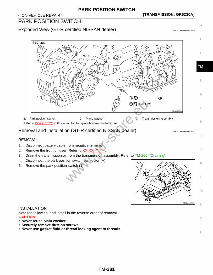
PARK POSITION SWITCH[TRANSMISSION: GR6Z30A]
C
E
F
G
H
I
J
K
L
M
A
B
M
N
O
P
< ON-VEHICLE REPAIR >
T
PARK POSITION SWITCH
Exploded View (GT-R certified NISSAN dealer) INFOID:0000000004020034
Removal and Installation (GT-R certified NISSAN dealer) INFOID:0000000004020035
REMOVAL1. Disconnect battery cable from negative terminal.2. Remove the front diffuser. Refer to XX-XX, "*****".3. Drain the transmission oil from the transmission assembly. Refer to TM-266, "Draining".4. Disconnect the park position switch connector (A).5. Remove the park position switch (1).
INSTALLATIONNote the following, and install in the reverse order of removal.CAUTION:• Never reuse plain washer.• Securely remove dust on screws.• Never use gasket fluid or thread locking agent to threads.
1. Park position switch 2. Plane washer 3. Transmission assembly
Refer to XX-XX, "*****" in GI section for the symbols shown in the figure.
NNDIA0038GB
NNDIA0039ZZ
www.gtr-
store
.eu
TM-281
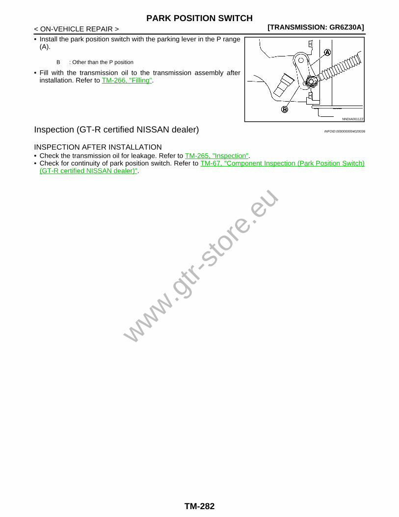
[TRANSMISSION: GR6Z30A]PARK POSITION SWITCH
< ON-VEHICLE REPAIR >• Install the park position switch with the parking lever in the P range
(A).
• Fill with the transmission oil to the transmission assembly afterinstallation. Refer to TM-266, "Filling".
Inspection (GT-R certified NISSAN dealer) INFOID:0000000004020036
INSPECTION AFTER INSTALLATION• Check the transmission oil for leakage. Refer to TM-265, "Inspection".• Check for continuity of park position switch. Refer to TM-67, "Component Inspection (Park Position Switch)
(GT-R certified NISSAN dealer)".
B : Other than the P position
NNDIA0011ZZ
www.gtr-
store
.eu
TM-282

HEAT EXCHANGER SYSTEM[TRANSMISSION: GR6Z30A]
C
E
F
G
H
I
J
K
L
M
A
B
M
N
O
P
< ON-VEHICLE REPAIR >
T
HEAT EXCHANGER SYSTEMHEAT EXCHANGER PIPING
HEAT EXCHANGER PIPING : Exploded View (GT-R certified NISSAN dealer)INFOID:0000000004020037
HEAT EXCHANGER PIPING : Removal and Installation (GT-R certified NISSAN deal-er) INFOID:0000000004020038
REMOVALCAUTION:Perform the operation when the engine is cold.1. Remove the front diffuser. Refer to XX-XX, "*****".2. Remove the sub-muffler. Refer to XX-XX, "*****".3. Remove the heat insulator.4. Remove the water tube, water hose C and water hose D from the vehicle.5. Remove the water outlet (rear) and heater pipe. Refer to XX-XX, "*****".6. Remove water hose A and water hose B from the water outlet (rear) and heater pipe.7. Remove the clips from water hose A and water hose B.
1. Clamp 2. Water hose A 3. Clips
4. Water hose B 5. Bracket 6. Insulator
7. Collar 8. Water tube 9. Water hose C
10. Water hose D 11. Transmission assembly
A. To water outlet (rear) B. To heater pipe
Refer to XX-XX, "*****" in GI section for the symbols shown in the figure.
NNDIA0008GB
www.gtr-
store
.eu
TM-283

[TRANSMISSION: GR6Z30A]HEAT EXCHANGER SYSTEM
< ON-VEHICLE REPAIR >
INSTALLATIONNote the following, and install in the reverse order of removal.CAUTION:• Never reuse clamps.• The clip is not reusable. Never reuse it.• Never reuse insulators.• Install the clips to water hose A (1) and water hose B (2) with the
paint mark (A) of hose in the direction shown in the figure.
• Refer to the following table when installing the water hose.
• Fill with the coolant after installation. Refer to XX-XX, "*****".
HEAT EXCHANGER PIPING : Inspection (GT-R certified NISSAN dealer) INFOID:0000000004020039
INSPECTION AFTER INSTALLATIONCheck the following items.
: Front of vehicle
NNDIA0065ZZ
Water hoseHose end
(Paint shape / Color)
Direction of hose paint mark
(Paint shape / Color)Hose insertion amount
Direction of clamp tab
Water hose A
Water outlet (rear)(— / —)
Rear of vehicle
( / Green)Until it contacts a tube end Rear of vehicle
Water tube(o / Green)
Right of vehicle(o / Green)
Until it reaches the point where the winding ra-dius stops
Right of vehicle
Water hose B
Heater pipe(— / —)
Upside of vehicle
( / Yellow)Until it contacts a tube end Upside of vehicle
Water tube(o / Yellow)
Right of vehicle(o / Yellow)
Until it reaches the point where the winding ra-dius stops
Downside of vehicle
Water hose C
Water tube(o / Green)
Right of vehicle
( / Pink)
Until the tube insertion indication stops
Right of vehicleHeat exchanger(— / Green)
Right of vehicle(o / Pink)
Water hose D
Water tube(o / Yellow)
Right of vehicle
( / Yellow)Right of vehicle
Heat exchanger(— / Blue)
Right of vehicle(o / Yellow)
www.gtr-
store
.eu
TM-284

HEAT EXCHANGER SYSTEM[TRANSMISSION: GR6Z30A]
C
E
F
G
H
I
J
K
L
M
A
B
M
N
O
P
< ON-VEHICLE REPAIR >
T
• Coolant leakage from the part removed and installed.• Coolant amount. Refer to XX-XX, "*****".HEAT EXCHANGER
HEAT EXCHANGER : Exploded View (GT-R certified NISSAN dealer) INFOID:0000000004020040
HEAT EXCHANGER : Removal and Installation (GT-R certified NISSAN dealer)INFOID:0000000004020041
REMOVALCAUTION:Be careful because the heat exchanger unit and transmission oil are hot during work.1. Remove the main muffler. Refer to XX-XX, "*****".2. Remove the heat insulator.3. Remove water hose C and water hose D from the heat exchanger. Refer to TM-283, "HEAT
EXCHANGER PIPING : Exploded View (GT-R certified NISSAN dealer)".
1. Spring washer 2. Plane washer 3. O-ring
4. Heat exchanger 5. Heat exchanger bracket 6. O-ring
7. O-ring 8. Transmission assembly
: Apply Genuine NISSAN Transmission oil R35 Special
Refer to XX-XX, "*****" in GI section for the symbols other than above.
NNDIA0024GB
www.gtr-
store
.eu
TM-285

[TRANSMISSION: GR6Z30A]HEAT EXCHANGER SYSTEM
< ON-VEHICLE REPAIR >4. Remove the heat exchanger (1).
5. Remove O-rings (1) and (2) from the heat exchanger.
6. Remove the heat exchanger bracket (1) from the transmissionassembly.
7. Remove O-ring (1) from the heat exchanger bracket.
INSTALLATIONNote the following, and install in the reverse order of removal.CAUTION:• Never reuse O-ring.• Apply the transmission oil to O-ring when the O-ring is installed to the heat exchanger.
: Bolt
NNDIA0028ZZ
NNDIA0029ZZ
: Bolt
NNDIA0030ZZ
NNDIA0031ZZ
www.gtr-
store
.eu
TM-286
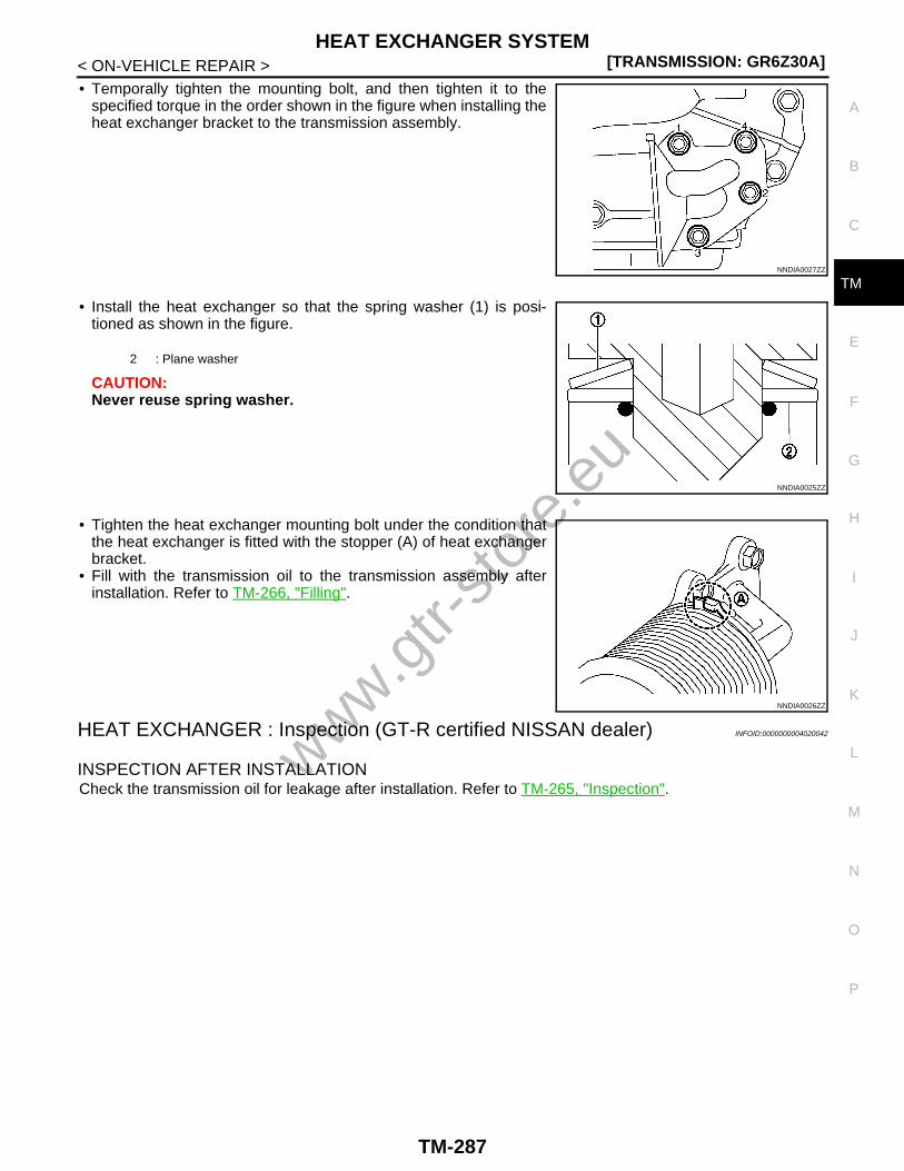
HEAT EXCHANGER SYSTEM[TRANSMISSION: GR6Z30A]
C
E
F
G
H
I
J
K
L
M
A
B
M
N
O
P
< ON-VEHICLE REPAIR >
T
• Temporally tighten the mounting bolt, and then tighten it to thespecified torque in the order shown in the figure when installing theheat exchanger bracket to the transmission assembly.
• Install the heat exchanger so that the spring washer (1) is posi-tioned as shown in the figure.
CAUTION:Never reuse spring washer.
• Tighten the heat exchanger mounting bolt under the condition thatthe heat exchanger is fitted with the stopper (A) of heat exchangerbracket.
• Fill with the transmission oil to the transmission assembly afterinstallation. Refer to TM-266, "Filling".
HEAT EXCHANGER : Inspection (GT-R certified NISSAN dealer) INFOID:0000000004020042
INSPECTION AFTER INSTALLATIONCheck the transmission oil for leakage after installation. Refer to TM-265, "Inspection".
NNDIA0027ZZ
2 : Plane washer
NNDIA0025ZZ
NNDIA0026ZZ
www.gtr-
store
.eu
TM-287
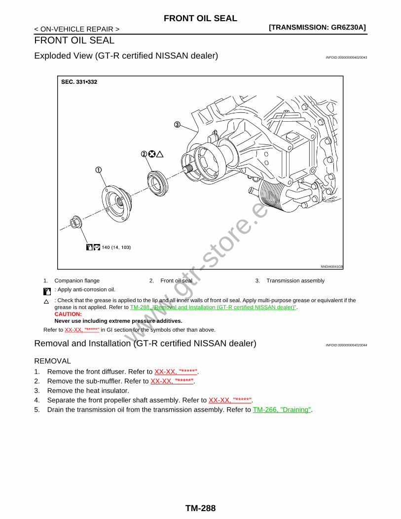
[TRANSMISSION: GR6Z30A]FRONT OIL SEAL
< ON-VEHICLE REPAIR >
FRONT OIL SEAL
Exploded View (GT-R certified NISSAN dealer) INFOID:0000000004020043
Removal and Installation (GT-R certified NISSAN dealer) INFOID:0000000004020044
REMOVAL1. Remove the front diffuser. Refer to XX-XX, "*****".2. Remove the sub-muffler. Refer to XX-XX, "*****".3. Remove the heat insulator. 4. Separate the front propeller shaft assembly. Refer to XX-XX, "*****".5. Drain the transmission oil from the transmission assembly. Refer to TM-266, "Draining".
1. Companion flange 2. Front oil seal 3. Transmission assembly
: Apply anti-corrosion oil.
: Check that the grease is applied to the lip and all inner walls of front oil seal. Apply multi-purpose grease or equivalent if the grease is not applied. Refer to TM-288, "Removal and Installation (GT-R certified NISSAN dealer)".CAUTION:Never use including extreme pressure additives.
Refer to XX-XX, "*****" in GI section for the symbols other than above.
NNDIA0041GB
www.gtr-
store
.eu
TM-288

FRONT OIL SEAL[TRANSMISSION: GR6Z30A]
C
E
F
G
H
I
J
K
L
M
A
B
M
N
O
P
< ON-VEHICLE REPAIR >
T
6. Install the flange wrench (commercial service tool) (A) to thecompanion flange of transfer, and then remove the mountingnut.
7. Remove companion flange using a puller (commercial servicetool) (A).CAUTION:Never damage the companion flange.
8. Remove the front oil seal using the puller [SST: KV381054S0 (J-34286)] (A).CAUTION:Never damage case.
INSTALLATIONNote the following, and install in the reverse order of removal.CAUTION:Apply anti-corrosion oil to threads and seat surfaces when installing the companion flange mountingnut.• Drive and install the front oil seal to the case end surface using a
drift.
CAUTION:• Never reuse oil seals.
NNDIA0074ZZ
NNDIA0075ZZ
NNDIA0076ZZ
A : Drift [SST: ST30720000 (J-25405)]
B : Drift [SST: KV40104830 ( — )]
NNDIA0108ZZ
www.gtr-
store
.eu
TM-289

[TRANSMISSION: GR6Z30A]FRONT OIL SEAL
< ON-VEHICLE REPAIR >• Check that the grease is applied to the lip and all inner walls
of oil seal. Apply multi-purpose grease or equivalent if thegrease is not applied.
- Never use including extreme pressure additives.• Never incline the oil seal during installation.• Never allow oil and dust, etc. to get on the oil seal press-fit-
ting surface.• Never damage the oil seal.• Never damage the front drive shaft when installing the oil
seal.NOTE:For OK/NG judgment of oil seal installation, measure the oil sealpress-fitting depth (on 2 locations or more) and check if they exceed the dimension “A”. Always calculate thedimension “A” before measurement. Dimension “A” can be calculated by the formula below.
• Fill with the transmission oil to the transmission assembly afterinstallation. Refer to TM-266, "Filling".
Inspection (GT-R certified NISSAN dealer) INFOID:0000000004020045
INSPECTION AFTER INSTALLATIONCheck the transmission oil for leakage. Refer to TM-265, "Inspection".
A = B - C - 0.5 mm (0.020 in)A : Oil seal press-fitting depthB : Case depthC : Oil seal flange thickness
NNDIA0134ZZ
NNDIA0077ZZ
www.gtr-
store
.eu
TM-290

TRANSMISSION ASSEMBLY[TRANSMISSION: GR6Z30A]
C
E
F
G
H
I
J
K
L
M
A
B
M
N
O
P
< REMOVAL AND INSTALLATION >
T
REMOVAL AND INSTALLATIONTRANSMISSION ASSEMBLY
Exploded View (GT-R certified NISSAN dealer) INFOID:0000000004020046
Removal and Installation (GT-R certified NISSAN dealer) INFOID:0000000004020047
REMOVAL1. Disconnect the transmission unit harness connector with the following procedure.
• Rotate the bayonet ring (A) counterclockwise, and then pullout the transmission unit harness connectors (B).
2. Remove the transmission assembly and rear suspensionassembly from the vehicle. Refer to XX-XX, "*****".
3. Remove the air breather hose from the transmission assembly.Refer to XX-XX, "*****".
4. Remove the transmission assembly from the rear suspensionassembly. Refer to XX-XX, "*****".
5. Remove the transmission mounting stay, mounting insulator,and bracket.CAUTION:• Never allow oil or grease to get on the mounting insulator. Never damage the tube.
1. Bracket 2. Mounting insulator 3. Transmission mounting stay
4. Bracket 5. Bracket 6. Transmission assembly
Refer to XX-XX, "*****" in GI section for the symbols shown in the figure.
NNDIA0014GB
NNDIA0129ZZ
www.gtr-
store
.eu
TM-291

[TRANSMISSION: GR6Z30A]TRANSMISSION ASSEMBLY
< REMOVAL AND INSTALLATION >• Never use an impact wrench to remove the mounting insulator from the transmission mounting
stay.6. Disconnect the rear cable. Refer to XX-XX, "*****".
INSTALLATIONNote the following, and install in the reverse order of removal.CAUTION:• Refer to TM-258, "Precautions for Replacement of TCM and Transmission Assembly" when the
transmission assembly is replaced.• Never allow oil or grease to get on the mounting insulator. Never damage the tube.• Never twist the rubber parts when installing the mounting insulator.• Never use an impact wrench to install the insulator to the transmission mounting stay.• Connect the transmission unit harness connector with the following procedure.
CAUTION:Connect harness connectors between the connectors of the same color.
1. Align the marking (A) of transmission connector terminal unitand the o marking (B) of bayonet ring, insert the transmissionunit harness connector, and then rotate the bayonet ring clock-wise.
2. Rotate the bayonet ring clockwise until the marking (A) oftransmission connector terminal unit and the slit (B) of bayonetring are aligned as shown in the figure (specified joint condition),and then connect the transmission unit harness connector to thetransmission connector terminal unit.
NOTE:• Securely align the positions of the marking (A) of transmission
connector terminal unit and the slit (B) of bayonet ring. In addition,avoid the partial joint condition as shown in the figure.
• Do not confuse the bayonet ring slit with other dents.
Inspection (GT-R certified NISSAN dealer) INFOID:0000000004020048
INSPECTION AFTER INSTALLATIONCheck the following items. • Transmission oil leakage. Refer to TM-265, "Inspection".• Check shift position. Adjust the shift position if necessary. Refer to TM-268, "Inspection and Adjustment".
JPDIA0294ZZ
JPDIA0295ZZ
JPDIA0296ZZ
www.gtr-
store
.eu
TM-292

FLY WHEEL HOUSING ASSEMBLY[TRANSMISSION: GR6Z30A]
C
E
F
G
H
I
J
K
L
M
A
B
M
N
O
P
< REMOVAL AND INSTALLATION >
T
FLY WHEEL HOUSING ASSEMBLY
Exploded View (GT-R certified NISSAN dealer) INFOID:0000000004020049
Removal and Installation (GT-R certified NISSAN dealer) INFOID:0000000004020050
REMOVAL1. Remove engine assembly from the vehicle. Refer to XX-XX, "*****".2. Disconnect the heated oxygen sensor 2 connector and harness from the heat insulator.3. Remove the three-way catalyst (bank 1) and (bank 2) from the engine assembly. Refer to XX-XX, "*****".4. Remove the heat insulator from the flywheel housing assembly.5. Remove the rear engine mounting insulator from the flywheel housing assembly. Refer to XX-XX, "*****".6. Remove the starter motor. Refer to XX-XX, "*****".7. Remove the crankshaft position sensor (POS). Refer to XX-XX, "*****".
CAUTION:• Never subject it to impact by dropping.• Never disassemble the sensor.• Check that metal powder does not adhere to magnetic area on top of sensor.• Keep the sensor away from magnetic materials.
1. Flywheel housing assembly 2. Heat insulator 3. Rear plate cover
4. Heat insulator
A. Refer to TM-293, "Removal and In-stallation (GT-R certified NISSAN dealer)" for tightening torque.
B. First step C. Second step
Refer to XX-XX, "*****" in GI section for the symbols shown in the figure.
NNDIA0007GB
www.gtr-
store
.eu
TM-293

[TRANSMISSION: GR6Z30A]FLY WHEEL HOUSING ASSEMBLY
< REMOVAL AND INSTALLATION >8. Remove the rear plate cover (1) using a screwdriver (A).
CAUTION:Never damage the flywheel housing assembly.
9. Rotate the crankshaft and remove the bolts ( : 6 places) thatsecure the flywheel to drive line torsional vibration damper.CAUTION:Rotate crankshaft clockwise (as viewed from the front ofthe engine).
10. Remove the mounting bolts of engine assembly and flywheelhousing assembly.
11. Remove the flywheel housing assembly from the engine assem-bly.
INSTALLATIONNote the following, and install in the reverse order of removal.• Check if the knock pins (2 each) of cylinder block and flywheel are
not dropped, adjust the flywheel knock pin position so that it isinserted into the knock pin insertion hole (convex shape) ( ) ofdrive line torsional vibration damper, and install them.
• Install the mounting bolts according to the standard below wheninstalling the flywheel housing assembly to the engine assembly.
NNDIA0109ZZ
NNDIA0003ZZ
NNDIA0037ZZ
Bolt symbolA
(Housing side → Engine side)
B(Housing side →
Engine side)
C(Engine side → Housing side)
Quantity 4 3 4
Nominal lengthmm (in)
65 (2.56) 40 (1.57) 40 (1.57)
Tightening torqueN·m (kg-m, ft-lb)
75 (7.7, 55) 34 (3.5, 25) 65 (6.6, 48) NNDIA0004ZZ
www.gtr-
store
.eu
TM-294

FLY WHEEL HOUSING ASSEMBLY[TRANSMISSION: GR6Z30A]
C
E
F
G
H
I
J
K
L
M
A
B
M
N
O
P
< REMOVAL AND INSTALLATION >
T
• Tighten the bolts of flywheel and drive line torsional vibrationdamper evenly in 2 steps as shown in the figure after temporarilytightening the bolt. The figure shows the view from the rear of thevehicle.
CAUTION:• Rotate crankshaft clockwise (as viewed from the front of the
engine).• Check the tightening torque for crankshaft pulley mounting
bolts after drive line torsional vibration damper bolts aretightened and crankshaft pulley mounting bolts are secured.
• Press the tabs (B) into the flywheel housing assembly after insert-ing the tabs (A) into the flywheel housing assembly when installingthe rear plate cover. The figure shows the view from the top of thevehicle.CAUTION:• Never reuse rear plate cover.• Check for installation direction.• Press surrounding area of tabs (B) when pressing the tabs
(B) in.• Never tap the cover when installing.• Check cover unit for excessive looseness and surrounding
embossment.
A : First step
B : Second step
C : Knock pin
NNDIA0005ZZ
NNDIA0110ZZ
www.gtr-
store
.eu
TM-295

[TRANSMISSION: GR6Z30A]FLY WHEEL HOUSING ASSEMBLY
< REMOVAL AND INSTALLATION >• Temporally tighten the mounting bolt, and then tighten it to the
specified torque in the order shown in the figure when installing theheat insulator to the flywheel housing assembly.
NNDIA0006ZZ
www.gtr-
store
.eu
TM-296

TRANSMISSION ASSEMBLY[TRANSMISSION: GR6Z30A]
C
E
F
G
H
I
J
K
L
M
A
B
M
N
O
P
< DISASSEMBLY AND ASSEMBLY >
T
DISASSEMBLY AND ASSEMBLYTRANSMISSION ASSEMBLY
Exploded View INFOID:0000000004020051
Disassembly and assembly (GT-R certified NISSAN dealer) INFOID:0000000004020052
DISASSEMBLYNOTE:For any parts other than filler plug, remove and replace only when a trace of oil leakage is detected.Be careful of the following items when removing the component parts.• Drain the transmission oil before removing the 3rd-5th check pin. Refer to TM-266, "Draining".• Stop the engine with the shift lever in the P position before removing the 3rd-5th check pin.
ASSEMBLYBe careful of the following items when installing the component parts.CAUTION:• Never reuse filler plug gasket.• Never reuse plain washer.• Never reuse O-ring.• Apply the transmission oil when installing the O-ring.
1. Transmission assembly 2. Filler plug 3. Filler plug gasket
4. 3rd-5th check pin 5. Plane washer 6. O-ring
7. Plug 8. Idler bolt 9. Plane washer
: Apply Genuine NISSAN Transmission oil R35 Special.
Refer to XX-XX, "*****" in GI section for the symbols other than above.
NNDIA0040GB
www.gtr-
store
.eu
TM-297

[TRANSMISSION: GR6Z30A]TRANSMISSION ASSEMBLY
< DISASSEMBLY AND ASSEMBLY >• Temporarily tighten by hand, and then tighten to the specified torque when installing the parts to the
transmission assembly.• Fill with the transmission oil after installation. Refer to TM-266, "Filling".
www.gtr-
store
.eu
TM-298

SERVICE DATA AND SPECIFICATIONS (SDS)[TRANSMISSION: GR6Z30A]
C
E
F
G
H
I
J
K
L
M
A
B
M
N
O
P
< SERVICE DATA AND SPECIFICATIONS (SDS)
T
SERVICE DATA AND SPECIFICATIONS (SDS)SERVICE DATA AND SPECIFICATIONS (SDS)
General Specification INFOID:0000000004020053
Applied modelVR38DETT
AWD
Transmission model GR6Z30A
Transmission
Transmission model code number(*1) JF00A
Operating system Remote control floor shifter and paddle shifter
Shift position
P Fixed to output shaft (engine start is possible)
R Reverse
N Neutral (engine start is possible)
A
R 1←→2←→3←→4←→5←→6
Normal 1←→2←→3←→4←→5←→6
SNOW 1←→2←→3←→4←→5←→6
M
R
6M Fixed to 6th gear
With the under rev protection au-tomatic shift function
5M Fixed to 5th gear
4M Fixed to 4th gear
3M Fixed to 3rd gear
2M Fixed to 2nd gear
1M Fixed to 1st gear
Normal
6M Fixed to 6th gear
With the over rev and under rev protection automatic shift function
5M Fixed to 5th gear
4M Fixed to 4th gear
3M Fixed to 3rd gear
2M Fixed to 2nd gear
1M Fixed to 1st gear
Gear ratio
1st gear 4.056
2nd gear 2.301
3rd gear 1.595
4th gear 1.248
5th gear 1.001
6th gear 0.796
Reverse 3.383
Control system Electronic controls
FunctionSelf-diagnosis function With
Fail safe function With
Synchronizer system Borg Warner type triple cone synchronizer
Oil pumpType External gear pump
Drive type Drive with the engine
OilRecommended Genuine NISSAN Transmission oil R35 Special
Capacity 9.7 liter (10-1/4 US qt, 8-1/2 Imp qt)(*2)
www.gtr-
store
.eu
TM-299

[TRANSMISSION: GR6Z30A]SERVICE DATA AND SPECIFICATIONS (SDS)
< SERVICE DATA AND SPECIFICATIONS (SDS) • *1: The model No. refers to the lower five digits of the part number (32000 XXXXX).
• *2: The indicated oil level is only a guide, therefore check the oil level according to the Service Manual.
Vehicle Speed at Which Gear Shifting Occurs (GT-R certified NISSAN dealer)INFOID:0000000004020054
Solenoid Valve (GT-R certified NISSAN dealer) INFOID:0000000004020055
Fluid Temperature Sensor (GT-R certified NISSAN dealer) INFOID:0000000004020056
Flywheel Housing Assembly (GT-R certified NISSAN dealer) INFOID:0000000004020057
Unit: mm (in)
Gear positionVehicle speed km/h (MPH)
Accelerator pedal position 4.0/8 Accelerator pedal position 8.0/8
UP
A1 → A2 41 – 45 (25 – 28) 51 – 55 (31 – 35)
A2 → A3 73 – 79 (45 – 50) 96 – 104 (59 – 65)
A3 → A4 101 – 109 (62 – 68) 141 – 151 (87 – 94)
A4 → A5 127 – 135 (78 – 84) 184 – 194 (114 – 121)
A5 → A6 156 – 164 (96 – 102) 231 – 241 (143 – 150)
DOWN
A6 → A5 124 – 132 (77 – 83) 170 – 180 (105 – 112)
A5 → A4 84 – 92 (52 – 58) 125 – 135 (77 – 84)
A4 → A3 41 – 49 (25 – 31) 76 – 86 (47 – 54)
A3 → A2 30 – 36 (18 – 23) 39 – 47 (24 – 30)
A2 → A1 0 (0) 0 (0)
Items
Transmission unit harness connector Resistance (Approx.)
Connector TerminalTransmission oil
temperature 20°C (68°F)
Transmission oil temperature 50°C (122°F)
Transmission oil temperature 80°C (176°F)
Shift solenoid valve 1
B49
13
Ground 6.6 – 7.4 Ω 7.3 – 8.3 Ω 8.1 – 9.2 Ω
Shift solenoid valve 2 20
Shift solenoid valve 3 27
Shift solenoid valve 4 7
Sequence solenoid valve 6
Axis A feed pressure solenoid valve 14 153.8 – 4.4 Ω 4.3 – 5.0 Ω 4.7 – 5.4 Ω
Axis B feed pressure solenoid valve 21 22
Clutch A solenoid valve
B50
37 384.6 – 5.0 Ω 5.1 – 5.6 Ω 5.6 – 6.2 Ω
Clutch B solenoid valve 42 43
Line pressure solenoid valve 48 493.8 – 4.4 Ω 4.3 – 5.0 Ω 4.7 – 5.4 Ω
Lubricating flow solenoid valve 54 55
Items
Transmission unit harness connector Resistance (Approx.)
Connector TerminalTransmission oil
temperature 20°C (68°F)
Transmission oil temperature 50°C (122°F)
Transmission oil temperature 80°C (176°F)
Fluid temperature sensor B50 45 46 6.36 – 6.68 kΩ 2.17 – 2.23 kΩ 0.86 – 0.89 kΩ
Radial play 0 – 0.55 (0 – 0.0217)
www.gtr-
store
.eu
TM-300