transmission & driveline tm a - boredmder -...
TRANSCRIPT
TRANSMISSION & DRIVELINE
C
E
SECTION TMA
B
M
TTRANSAXLE & TRANSMISSION
F
G
H
I
J
K
L
M
N
O
P
CONTENTS
CVT: RE0F10A
BASIC INSPECTION .................................... 6
DIAGNOSIS AND REPAIR WORK FLOW ......... 6Work Flow .................................................................6Diagnostic Work Sheet ..............................................7
INSPECTION AND ADJUSTMENT ..................... 9
ADDITIONAL SERVICE WHEN REPLACING CONTROL UNIT ..........................................................9
ADDITIONAL SERVICE WHEN REPLACING CONTROL UNIT : Service After Replacing TCM, Transaxle Assembly and Control Valve ....................9
FUNCTION DIAGNOSIS ..............................11
CVT SYSTEM .....................................................11System Diagram ......................................................11Component Parts Location ......................................12
MECHANICAL SYSTEM ....................................15Cross-Sectional View ..............................................15System Diagram ......................................................16System Description .................................................16Component Parts Location ......................................17Component Description ...........................................19
HYDRAULIC CONTROL SYSTEM ....................20System Diagram ......................................................20System Description .................................................20Component Parts Location ......................................21Component Description ...........................................23
CONTROL SYSTEM ..........................................25System Diagram ......................................................25System Description .................................................25Component Parts Location ......................................27Component Description ...........................................29
LOCK-UP AND SELECT CONTROL SYSTEM ....30
System Diagram ......................................................30System Description ..................................................30Component Parts Location ......................................31Component Description ...........................................33
SHIFT CONTROL SYSTEM ..............................34System Diagram ......................................................34System Description ..................................................34Component Parts Location ......................................35Component Description ...........................................38
SHIFT LOCK SYSTEM .....................................39System Description ..................................................39Component Parts Location ......................................41Component Description ...........................................41
ON BOARD DIAGNOSTIC (OBD) SYSTEM ....42Diagnosis Description ..............................................42
DIAGNOSIS SYSTEM (TCM) ............................44CONSULT-III Function (TRANSMISSION) ..............44Diagnostic Tool Function .........................................47
COMPONENT DIAGNOSIS .........................48
U1000 CAN COMM CIRCUIT ...........................48Description ...............................................................48DTC Logic ................................................................48Diagnosis Procedure ...............................................48
U1010 CONTROL UNIT (CAN) .........................49Description ...............................................................49DTC Logic ................................................................49Diagnosis Procedure ...............................................49
P0703 STOP LAMP SWITCH ...........................50Description ...............................................................50DTC Logic ................................................................50Diagnosis Procedure ...............................................50Component Inspection (Stop Lamp Switch) ............51
P0705 PARK/NEUTRAL POSITION SWITCH ...53Description ...............................................................53
TM-1Revision: 2008 August 2009 Rogue

DTC Logic ............................................................... 53Diagnosis Procedure .............................................. 53Component Inspection (Park/Neutral Position Switch) .................................................................... 54
P0710 CVT FLUID TEMPERATURE SENSOR ... 56
Description .............................................................. 56DTC Logic ............................................................... 56Diagnosis Procedure .............................................. 56Component Inspection (CVT Fluid Temperature Sensor) ................................................................... 58
P0715 INPUT SPEED SENSOR (PRI SPEED SENSOR) ........................................................... 59
Description .............................................................. 59DTC Logic ............................................................... 59Diagnosis Procedure .............................................. 59
P0720 VEHICLE SPEED SENSOR CVT (SEC-ONDARY SPEED SENSOR) ............................. 63
Description .............................................................. 63DTC Logic ............................................................... 63Diagnosis Procedure .............................................. 63
P0725 ENGINE SPEED SIGNAL ...................... 67Description .............................................................. 67DTC Logic ............................................................... 67Diagnosis Procedure .............................................. 67
P0730 BELT DAMAGE ...................................... 68Description .............................................................. 68DTC Logic ............................................................... 68Diagnosis Procedure .............................................. 68
P0740 TORQUE CONVERTER CLUTCH SO-LENOID VALVE ................................................. 69
Description .............................................................. 69DTC Logic ............................................................... 69Diagnosis Procedure .............................................. 69Component Inspection (Torque Converter Clutch Solenoid Valve) ...................................................... 70
P0744 A/T TCC S/V FUNCTION (LOCK-UP) .... 71Description .............................................................. 71DTC Logic ............................................................... 71Diagnosis Procedure .............................................. 71Component Inspection (Torque Converter Clutch Solenoid Valve) ...................................................... 72Component Inspection (Lock-up Select Solenoid Valve) ..................................................................... 72
P0745 LINE PRESSURE SOLENOID VALVE ... 73Description .............................................................. 73DTC Logic ............................................................... 73Diagnosis Procedure .............................................. 73Component Inspection [Pressure Control Sole-noid Valve A (Line Pressure Solenoid Valve)] ........ 74
P0746 PRESSURE CONTROL SOLENOID A PERFORMANCE (LINE PRESSURE SOLE-NOID VALVE) .................................................... 75
Description .............................................................. 75DTC Logic ............................................................... 75Diagnosis Procedure ............................................... 75Component Inspection [Pressure Control Sole-noid Valve A (Line Pressure Solenoid Valve)] ........ 76
P0776 PRESSURE CONTROL SOLENOID B PERFORMANCE (SEC PRESSURE SOLE-NOID VALVE) .................................................... 77
Description .............................................................. 77DTC Logic ............................................................... 77Diagnosis Procedure ............................................... 77Component Inspection [Pressure Control Sole-noid Valve A (Line Pressure Solenoid Valve)] ........ 78Component Inspection [Pressure Control Sole-noid Valve B (Secondary Pressure Solenoid Valve)] ..................................................................... 78
P0778 PRESSURE CONTROL SOLENOID B ELECTRICAL (SEC PRESSURE SOLENOID VALVE) .............................................................. 80
Description .............................................................. 80DTC Logic ............................................................... 80Diagnosis Procedure ............................................... 80Component Inspection [Pressure Control Sole-noid Valve B (Secondary Pressure Solenoid Valve)] ..................................................................... 81
P0826 MANUAL MODE SWITCH ..................... 82Description .............................................................. 82DTC Logic ............................................................... 82Diagnosis Procedure ............................................... 82Component Inspection (Manual Mode Switch) ....... 85Component Inspection (Paddle Shifter) .................. 86Component Inspection (Spiral Cable) ..................... 86
P0840 TRANSMISSION FLUID PRESSURE SENSOR A (SEC PRESSURE SENSOR) ......... 87
Description .............................................................. 87DTC Logic ............................................................... 87Diagnosis Procedure ............................................... 87
P0841 PRESSURE SENSOR FUNCTION ........ 90Description .............................................................. 90DTC Logic ............................................................... 90Diagnosis Procedure ............................................... 90Component Inspection [Pressure Control Sole-noid Valve A (Line Pressure Solenoid Valve)] ........ 91Component Inspection [Pressure Control Sole-noid Valve B (Secondary Pressure Solenoid Valve)] ..................................................................... 91
P0868 SECONDARY PRESSURE DOWN ........ 92Description .............................................................. 92DTC Logic ............................................................... 92Diagnosis Procedure ............................................
TM-2Revision: 2008 August 2009 Rogue
C
E
F
G
H
I
J
K
L
M
A
B
M
N
O
P
T
Component Inspection [Pressure Control Sole-noid Valve A (Line Pressure Solenoid Valve)] ........93Component Inspection [Pressure Control Sole-noid Valve B (Secondary Pressure Solenoid Valve)] .....................................................................93
P1701 TRANSMISSION CONTROL MODULE (POWER SUPPLY) .............................................95
Description ..............................................................95DTC Logic ...............................................................95Diagnosis Procedure ...............................................95
P1705 THROTTLE POSITION SENSOR ...........98Description ..............................................................98DTC Logic ...............................................................98Diagnosis Procedure ...............................................98
P1722 ESTM VEHICLE SPEED SIGNAL ..........99Description ..............................................................99DTC Logic ...............................................................99Diagnosis Procedure ...............................................99
P1723 CVT SPEED SENSOR FUNCTION ...... 101Description ............................................................ 101DTC Logic ............................................................. 101Diagnosis Procedure ............................................. 101
P1726 ELECTRIC THROTTLE CONTROL SYSTEM ........................................................... 103
Description ............................................................ 103DTC Logic ............................................................. 103Diagnosis Procedure ............................................. 103
P1740 LOCK-UP SELECT SOLENOID VALVE .............................................................. 104
Description ............................................................ 104DTC Logic ............................................................. 104Diagnosis Procedure ............................................. 104Component Inspection (Lock-up Select Solenoid Valve) .................................................................... 105
P1745 LINE PRESSURE CONTROL ............... 106Description ............................................................ 106DTC Logic ............................................................. 106Diagnosis Procedure ............................................. 106
P1777 STEP MOTOR ....................................... 107Description ............................................................ 107DTC Logic ............................................................. 107Diagnosis Procedure ............................................. 107Component Inspection (Step Motor) ..................... 109
P1778 STEP MOTOR - FUNCTION ................. 110Description ............................................................ 110DTC Logic ............................................................. 110Diagnosis Procedure ............................................. 110
SHIFT POSITION INDICATOR CIRCUIT ......... 112
WITHOUT MANUAL MODE .................................... 112WITHOUT MANUAL MODE : Description ............. 112
WITHOUT MANUAL MODE : Component Func-tion Check ..............................................................112WITHOUT MANUAL MODE : Diagnosis Proce-dure .......................................................................112
WITH MANUAL MODE ............................................112WITH MANUAL MODE : Description .....................112WITH MANUAL MODE : Component Function Check ....................................................................112WITH MANUAL MODE : Diagnosis Procedure .....113
SHIFT LOCK SYSTEM ................................... 114Description .............................................................114Wiring Diagram - CVT SHIFT LOCK SYSTEM - ...114Component Function Check ..................................116Diagnosis Procedure .............................................117Component Inspection (Stop Lamp Switch) ..........119Component Inspection (Shift Lock Solenoid) ........119
OVERDRIVE CONTROL SWITCH .................. 120Description .............................................................120Component Function Check ..................................120Diagnosis Procedure .............................................120Component Inspection (Overdrive Control Switch)
..121
ECU DIAGNOSIS ....................................... 122
TCM ................................................................. 122Reference Value ....................................................122Wiring Diagram - CVT CONTROL SYSTEM - .......127Fail-safe .................................................................131DTC Inspection Priority Chart ................................132DTC Index .............................................................133
SYMPTOM DIAGNOSIS ............................ 134
SYSTEM SYMPTOM ....................................... 134Symptom Table .....................................................134
PRECAUTION ............................................ 146
PRECAUTIONS ............................................... 146
FOR USA AND CANADA ........................................146FOR USA AND CANADA : Precaution for Supple-mental Restraint System (SRS) "AIR BAG" and "SEAT BELT PRE-TENSIONER" ..........................146FOR USA AND CANADA : Precaution Necessary for Steering Wheel Rotation After Battery Discon-nect ........................................................................146FOR USA AND CANADA : Precaution for Proce-dure without Cowl Top Cover ................................147FOR USA AND CANADA : Precaution for On Board Diagnosis (OBD) System of CVT and En-gine ........................................................................147FOR USA AND CANADA : Precaution for TCM, CVT Assembly and Control Valve Replacement ...147FOR USA AND CANADA : Removal and Installa-tion Procedure for CVT Unit Connector .................147FOR USA AND CANADA : Precaution ..................148
TM-3Revision: 2008 August 2009 Rogue

FOR USA AND CANADA : Service Notice or Pre-caution ...................................................................149FOR USA AND CANADA : ATFTEMP COUNT Conversion Table ..................................................150
FOR MEXICO ...........................................................150FOR MEXICO : Precaution for Supplemental Re-straint System (SRS) "AIR BAG" and "SEAT BELT PRE-TENSIONER" ................................................150FOR MEXICO : Precaution Necessary for Steer-ing Wheel Rotation After Battery Disconnect ........150FOR MEXICO : Precaution for Procedure without Cowl Top Cover .....................................................151FOR MEXICO : Precaution for On Board Diagno-sis (OBD) System of CVT and Engine ...................151FOR MEXICO : Precaution for TCM, CVT Assem-bly and Control Valve Replacement ......................152FOR MEXICO : Removal and Installation Proce-dure for CVT Unit Connector .................................152FOR MEXICO : Precaution ....................................153FOR MEXICO : Service Notice or Precaution .......154FOR MEXICO : ATFTEMP COUNT Conversion Table ......................................................................154
PREPARATION ..........................................156
PREPARATION ............................................... 156Special Service Tools ............................................156Commercial Service Tools .....................................156
ON-VEHICLE MAINTENANCE ..................158
CVT FLUID ....................................................... 158Inspection ..............................................................158Changing ...............................................................159
CVT FLUID COOLER SYSTEM ...................... 160Cleaning ................................................................160
STALL TEST .................................................... 163Inspection and Judgment ......................................163
LINE PRESSURE TEST .................................. 165Inspection and Judgment ......................................165
ROAD TEST ..................................................... 167Description .............................................................167Check before Engine Is Started .............................167Check at Idle ..........................................................167Cruise Test ............................................................168
CVT POSITION ................................................ 172
WITHOUT MANUAL MODE .....................................172WITHOUT MANUAL MODE : Inspection and Ad-justment .................................................................172
WITH MANUAL MODE ............................................172WITH MANUAL MODE : Inspection and Adjust-ment .......................................................................172
ON-VEHICLE REPAIR ...............................174
TRANSMISSION CONTROL MODULE ...........174Exploded View ...................................................... 174Removal and Installation ....................................... 174Adjustment ............................................................ 175
CONTROL DEVICE ..........................................176
WITHOUT MANUAL MODE .................................... 176WITHOUT MANUAL MODE : Exploded View ....... 176WITHOUT MANUAL MODE : Removal and Instal-lation ..................................................................... 176WITHOUT MANUAL MODE : Inspection and Ad-justment ................................................................ 178
WITH MANUAL MODE ........................................... 178WITH MANUAL MODE : Exploded View .............. 178WITH MANUAL MODE : Removal and Installation . 179WITH MANUAL MODE : Inspection and Adjust-ment ...................................................................... 180
CONTROL CABLE ...........................................181Exploded View ...................................................... 181Removal and Installation ....................................... 181Inspection and Adjustment .................................... 182
KEY INTERLOCK CABLE ...............................183Exploded View ...................................................... 183Removal and Installation ....................................... 183Inspection .............................................................. 184
CONTROL VALVE ...........................................185Exploded View ...................................................... 185Removal and Installation ....................................... 185Inspection and Adjustment .................................... 191
PARK/NEUTRAL POSITION (PNP) SWITCH ..192Exploded View ...................................................... 192Removal and Installation ....................................... 192Inspection and Adjustment .................................... 193
PRIMARY SPEED SENSOR ............................194Exploded View ...................................................... 194Removal and Installation ....................................... 194Inspection .............................................................. 194
SECONDARY SPEED SENSOR ......................195Exploded View ...................................................... 195Removal and Installation ....................................... 195Inspection .............................................................. 195
DIFFERENTIAL SIDE OIL SEAL .....................196
2WD ......................................................................... 1962WD : Exploded View ........................................... 1962WD : Removal and Installation ............................ 1962WD : Inspection ................................................... 197
AWD ........................................................................ 197AWD : Exploded View ........................................... 197AWD : Removal and Installation ........................... 197AWD : Inspection .................................................. 198
TM-4Revision: 2008 August 2009 Rogue
C
E
F
G
H
I
J
K
L
M
A
B
M
N
O
P
T
OIL PUMP FITTING BOLT ............................... 199Description ............................................................ 199Exploded View ...................................................... 199Removal and Installation ....................................... 199Inspection .............................................................. 199
AIR BREATHER HOSE .................................... 200Exploded View ...................................................... 200Removal and Installation ....................................... 200
FLUID COOLER SYSTEM ............................... 201
WATER HOSE (WITHOUT FLUID COOLER) ......... 201WATER HOSE (WITHOUT FLUID COOLER) : Exploded View ...................................................... 201WATER HOSE (WITHOUT FLUID COOLER) : Removal and Installation ....................................... 201WATER HOSE (WITHOUT FLUID COOLER) : In-spection ................................................................. 203
WATER HOSE (WITH FLUID COOLER) ................ 203WATER HOSE (WITH FLUID COOLER) : Explod-ed View ................................................................. 204WATER HOSE (WITH FLUID COOLER) : Remov-al and Installation .................................................. 204WATER HOSE (WITH FLUID COOLER) : Inspec-tion ........................................................................ 206
FLUID COOLER ...................................................... 206FLUID COOLER : Exploded view ......................... 207FLUID COOLER : Removal and Installation ......... 207FLUID COOLER : Inspection ................................ 209
REMOVAL AND INSTALLATION ............. 210
TRANSAXLE ASSEMBLY ............................... 210
2WD ..........................................................................2102WD : Exploded View ............................................2102WD : Removal and Installation ............................2102WD : Inspection ...................................................213
AWD .........................................................................213AWD : Exploded View ...........................................214AWD : Removal and Installation ............................214AWD : Inspection ...................................................217
DISASSEMBLY AND ASSEMBLY ............ 218
TORQUE CONVERTER AND CONVERTER HOUSING OIL SEAL ...................................... 218
Exploded View .......................................................218Disassembly ..........................................................218Assembly ...............................................................218Inspection ..............................................................219
SERVICE DATA AND SPECIFICATIONS (SDS) .......................................................... 220
SERVICE DATA AND SPECIFICATIONS (SDS) ............................................................... 220
General Specification ............................................220Vehicle Speed When Shifting Gears .....................220Stall Speed ............................................................220Line Pressure ........................................................220Solenoid Valves .....................................................221CVT Fluid Temperature Sensor .............................221Primary Speed Sensor ..........................................221Secondary Speed Sensor ......................................221Heater Thermostat .................................................221Torque Converter ..................................................221
TM-5Revision: 2008 August 2009 Rogue
[CVT: RE0F10A]DIAGNOSIS AND REPAIR WORK FLOW
< BASIC INSPECTION >
BASIC INSPECTIONDIAGNOSIS AND REPAIR WORK FLOW
Work Flow INFOID:0000000004235354
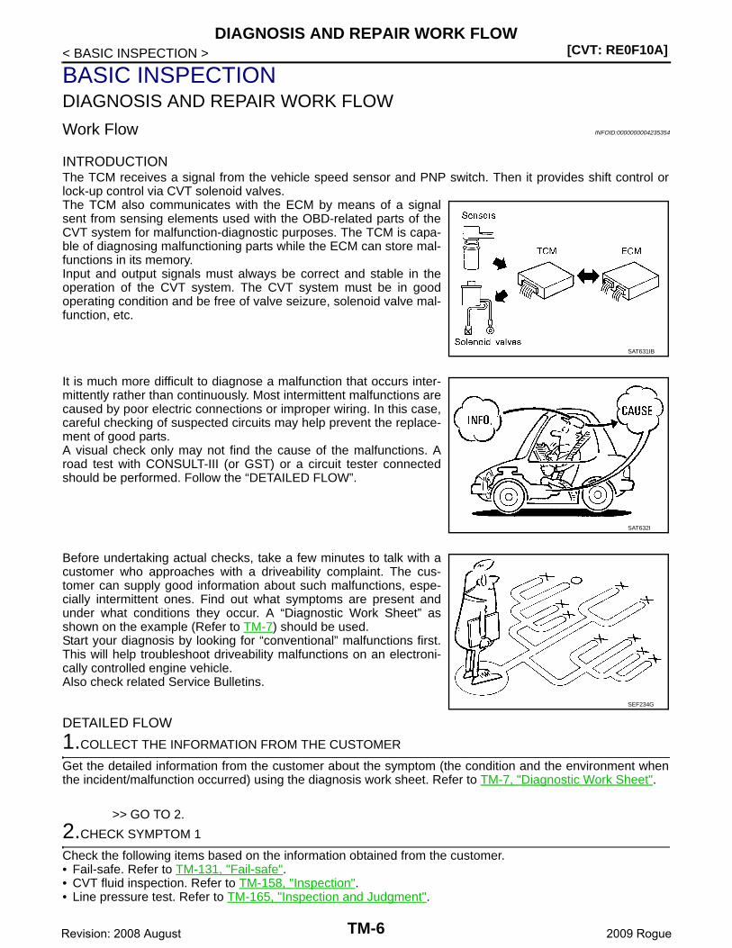
INTRODUCTIONThe TCM receives a signal from the vehicle speed sensor and PNP switch. Then it provides shift control orlock-up control via CVT solenoid valves.The TCM also communicates with the ECM by means of a signalsent from sensing elements used with the OBD-related parts of theCVT system for malfunction-diagnostic purposes. The TCM is capa-ble of diagnosing malfunctioning parts while the ECM can store mal-functions in its memory.Input and output signals must always be correct and stable in theoperation of the CVT system. The CVT system must be in goodoperating condition and be free of valve seizure, solenoid valve mal-function, etc.
It is much more difficult to diagnose a malfunction that occurs inter-mittently rather than continuously. Most intermittent malfunctions arecaused by poor electric connections or improper wiring. In this case,careful checking of suspected circuits may help prevent the replace-ment of good parts.A visual check only may not find the cause of the malfunctions. Aroad test with CONSULT-III (or GST) or a circuit tester connectedshould be performed. Follow the “DETAILED FLOW”.
Before undertaking actual checks, take a few minutes to talk with acustomer who approaches with a driveability complaint. The cus-tomer can supply good information about such malfunctions, espe-cially intermittent ones. Find out what symptoms are present andunder what conditions they occur. A “Diagnostic Work Sheet” asshown on the example (Refer to TM-7) should be used.Start your diagnosis by looking for “conventional” malfunctions first.This will help troubleshoot driveability malfunctions on an electroni-cally controlled engine vehicle.Also check related Service Bulletins.
DETAILED FLOW
1.COLLECT THE INFORMATION FROM THE CUSTOMER
Get the detailed information from the customer about the symptom (the condition and the environment whenthe incident/malfunction occurred) using the diagnosis work sheet. Refer to TM-7, "Diagnostic Work Sheet".
>> GO TO 2.
2.CHECK SYMPTOM 1
Check the following items based on the information obtained from the customer.• Fail-safe. Refer to TM-131, "Fail-safe".• CVT fluid inspection. Refer to TM-158, "Inspection".• Line pressure test. Refer to TM-165, "Inspection and Judgment".
SAT631IB
SAT632I
SEF234G
TM-6Revision: 2008 August 2009 Rogue
DIAGNOSIS AND REPAIR WORK FLOW[CVT: RE0F10A]
C
E
F
G
H
I
J
K
L
M
A
B
M
N
O
P
< BASIC INSPECTION >
T
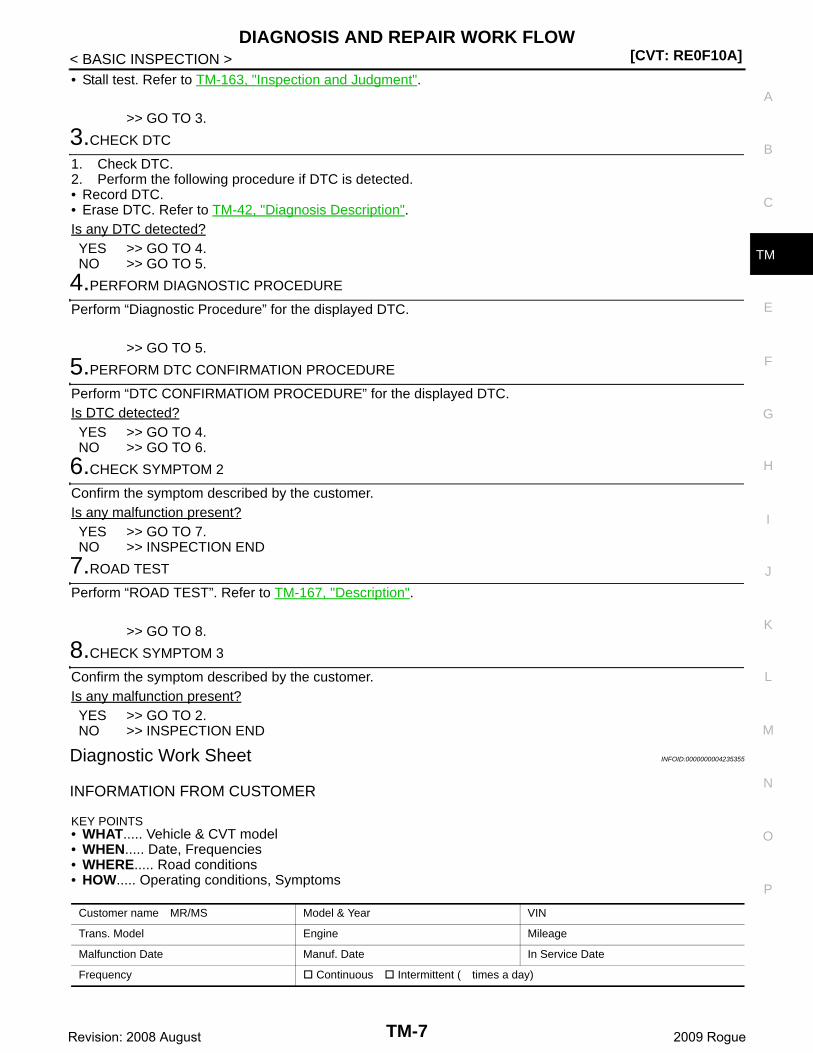
• Stall test. Refer to TM-163, "Inspection and Judgment".
>> GO TO 3.
3.CHECK DTC
1. Check DTC.2. Perform the following procedure if DTC is detected.• Record DTC.• Erase DTC. Refer to TM-42, "Diagnosis Description".Is any DTC detected?YES >> GO TO 4.NO >> GO TO 5.
4.PERFORM DIAGNOSTIC PROCEDURE
Perform “Diagnostic Procedure” for the displayed DTC.
>> GO TO 5.
5.PERFORM DTC CONFIRMATION PROCEDURE
Perform “DTC CONFIRMATIOM PROCEDURE” for the displayed DTC.Is DTC detected?YES >> GO TO 4.NO >> GO TO 6.
6.CHECK SYMPTOM 2
Confirm the symptom described by the customer.Is any malfunction present?YES >> GO TO 7.NO >> INSPECTION END
7.ROAD TEST
Perform “ROAD TEST”. Refer to TM-167, "Description".
>> GO TO 8.
8.CHECK SYMPTOM 3
Confirm the symptom described by the customer.Is any malfunction present?YES >> GO TO 2.NO >> INSPECTION END
Diagnostic Work Sheet INFOID:0000000004235355
INFORMATION FROM CUSTOMER
KEY POINTS• WHAT..... Vehicle & CVT model• WHEN..... Date, Frequencies• WHERE..... Road conditions• HOW..... Operating conditions, Symptoms
Customer name MR/MS Model & Year VIN
Trans. Model Engine Mileage
Malfunction Date Manuf. Date In Service Date
Frequency Continuous Intermittent ( times a day)
TM-7Revision: 2008 August 2009 Rogue
[CVT: RE0F10A]DIAGNOSIS AND REPAIR WORK FLOW
< BASIC INSPECTION >
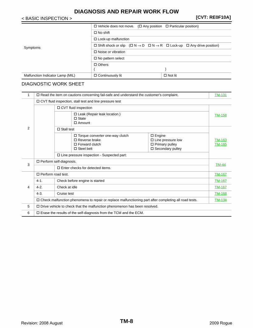
DIAGNOSTIC WORK SHEET
Symptoms
Vehicle does not move. ( Any position Particular position)
No shift
Lock-up malfunction
Shift shock or slip ( N → D N → R Lock-up Any drive position)
Noise or vibration
No pattern select
Others( )
Malfunction Indicator Lamp (MIL) Continuously lit Not lit
1 Read the item on cautions concerning fail-safe and understand the customer's complaint. TM-131
2
CVT fluid inspection, stall test and line pressure test
CVT fluid inspection
TM-158 Leak (Repair leak location.) State Amount
Stall test
TM-163TM-165
Torque converter one-way clutch Reverse brake Forward clutch Steel belt
Engine Line pressure low Primary pulley Secondary pulley
Line pressure inspection - Suspected part:
3 Perform self-diagnosis.
TM-44 Enter checks for detected items.
4
Perform road test. TM-167
4-1. Check before engine is started TM-167
4-2. Check at idle TM-167
4-3. Cruise test TM-168
Check malfunction phenomena to repair or replace malfunctioning part after completing all road tests. TM-134
5 Drive vehicle to check that the malfunction phenomenon has been resolved.
6 Erase the results of the self-diagnosis from the TCM and the ECM.
TM-8Revision: 2008 August 2009 Rogue

INSPECTION AND ADJUSTMENT[CVT: RE0F10A]
C
E
F
G
H
I
J
K
L
M
A
B
M
N
O
P
< BASIC INSPECTION >
T
INSPECTION AND ADJUSTMENTADDITIONAL SERVICE WHEN REPLACING CONTROL UNIT
ADDITIONAL SERVICE WHEN REPLACING CONTROL UNIT : Service After Replac-ing TCM, Transaxle Assembly and Control Valve INFOID:0000000004461069
SERVICE AFTER REPLACING TCM, TRANSAXLE ASSEMBLY OR CONTROL VALVEPerform the applicable service according to the following table when replacing TCM or transaxle assembly.CAUTION:• Never start the engine until the service is completed.• “DTC P1701” may be indicated soon after replacing TCM or transaxle assembly (after erasing the
memory in the pattern B). Restart the self-diagnosis after erasing the self-diagnosis result usingCONSULT-III. Check that no error is detected.
NOTE:
Old unit means that the unit has been already used for another vehicle.
PATTERN A1. Shift the selector lever to “P” position after replacing TCM.2. Turn ignition switch ON.3. Check that the shift position indicator in the combination meter turns ON (It indicates approximately 1 or 2
seconds after turning ignition switch ON.)• Check the following items if shift position indicator does not turn ON. Repair or replace accordingly as
necessary.- The harness between TCM and ROM ASSY in transaxle assembly is open or shorted.- Terminals disconnected, loose, or bent from connector housing.
PATTERN B1. Turn ignition switch ON after replacing each part.2. Connect the vehicle with CONSULT-III.3. Start engine.
CAUTION:Never start driving.
4. Select “Data monitor” in “TRANSMISSION”.5. Warm up transaxle assembly until “ATFTEMP COUNT” indicates 47 [approximately 20°C (68°F)] or more,
and then turn ignition switch OFF.6. Turn ignition switch ON.
CAUTION:Never start engine.
7. Select “Self Diagnostic Results” in “TRANSMISSION”.8. Shift the selector lever to “R” position.9. Depress slightly the accelerator pedal (Pedal angle: 2/8) while depressing the brake pedal. 10. Select “Erase”.11. Turn ignition switch OFF while keeping the selector lever in “R” position.12. Wait approximately 10 seconds.13. Turn ignition switch ON while keeping the selector lever in “R” position.
CAUTION:Never start engine.
TCM Transaxle assembly or contorl valve Service pattern
Replaced with new unit Not replaced the unit “PATTERN A”
Not replaced the unit Replaced with new or old unit
“PATTERN B”Replaced with old unit
Not replaced the unit
Replaced with new or old unit
Replaced with new unit Replaced with new or old unit “PATTERN C”
TM-9Revision: 2008 August 2009 Rogue
[CVT: RE0F10A]INSPECTION AND ADJUSTMENT
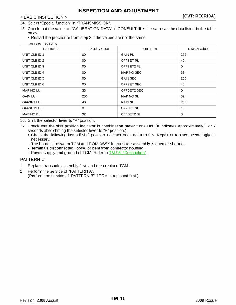
< BASIC INSPECTION >14. Select “Special function” in “TRANSMISSION”.15. Check that the value on “CALIBRATION DATA” in CONSULT-III is the same as the data listed in the table
below.• Restart the procedure from step 3 if the values are not the same.
CALIBRATION DATA
16. Shift the selector lever to “P” position.17. Check that the shift position indicator in combination meter turns ON. (It indicates approximately 1 or 2
seconds after shifting the selector lever to “P” position.)• Check the following items if shift position indicator does not turn ON. Repair or replace accordingly as
necessary.- The harness between TCM and ROM ASSY in transaxle assembly is open or shorted.- Terminals disconnected, loose, or bent from connector housing.- Power supply and ground of TCM. Refer to TM-95, "Description".
PATTERN C1. Replace transaxle assembly first, and then replace TCM.2. Perform the service of “PATTERN A”.
(Perform the service of “PATTERN B” if TCM is replaced first.)
Item name Display value Item name Display value
UNIT CLB ID 1 00 GAIN PL 256
UNIT CLB ID 2 00 OFFSET PL 40
UNIT CLB ID 3 00 OFFSET2 PL 0
UNIT CLB ID 4 00 MAP NO SEC 32
UNIT CLB ID 5 00 GAIN SEC 256
UNIT CLB ID 6 00 OFFSET SEC 40
MAP NO LU 33 OFFSET2 SEC 0
GAIN LU 256 MAP NO SL 32
OFFSET LU 40 GAIN SL 256
OFFSET2 LU 0 OFFSET SL 40
MAP NO PL 32 OFFSET2 SL 0
TM-10Revision: 2008 August 2009 Rogue
CVT SYSTEM[CVT: RE0F10A]
C
E
F
G
H
I
J
K
L
M
A
B
M
N
O
P
< FUNCTION DIAGNOSIS >
T
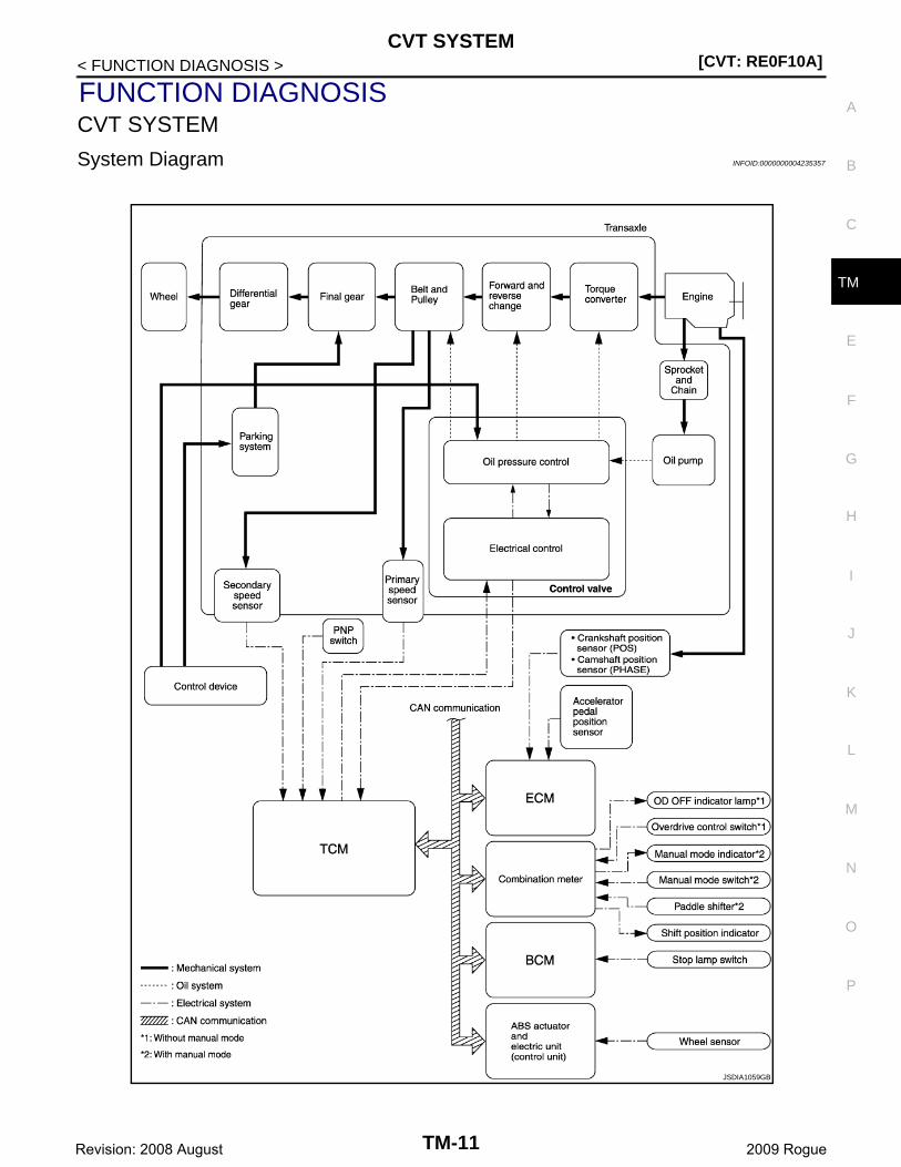
FUNCTION DIAGNOSISCVT SYSTEM
System Diagram INFOID:0000000004235357
JSDIA1059GB
TM-11Revision: 2008 August 2009 Rogue
[CVT: RE0F10A]CVT SYSTEM
< FUNCTION DIAGNOSIS >
Component Parts Location INFOID:0000000004490744
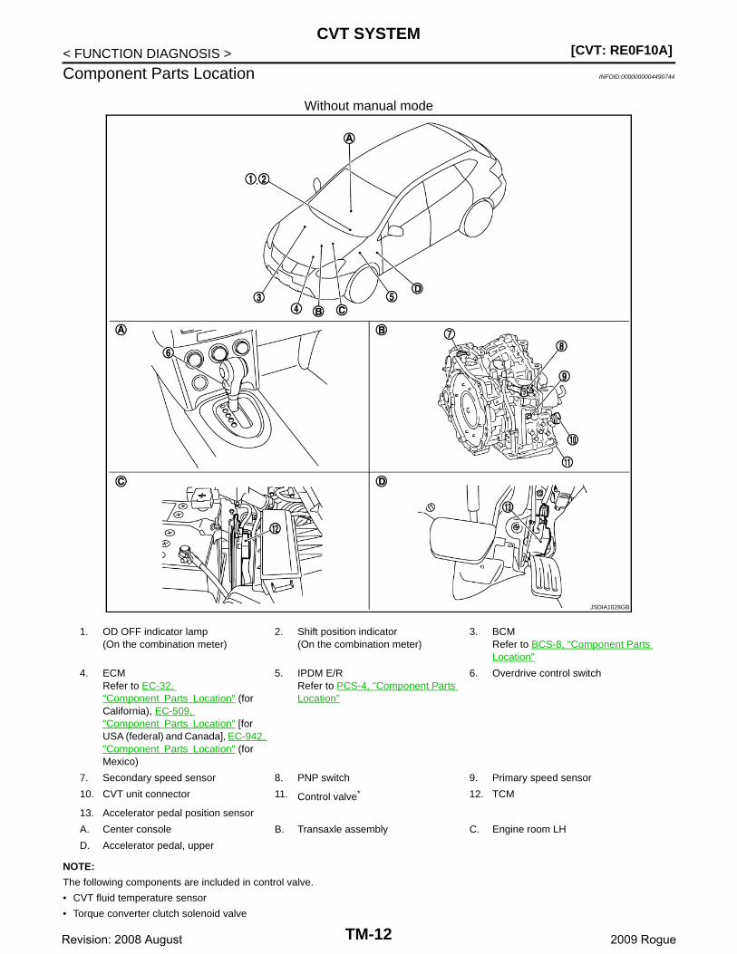
Without manual mode
NOTE:
The following components are included in control valve.
• CVT fluid temperature sensor
• Torque converter clutch solenoid valve
JSDIA1028GB
1. OD OFF indicator lamp(On the combination meter)
2. Shift position indicator(On the combination meter)
3. BCMRefer to BCS-8, "Component Parts Location"
4. ECMRefer to EC-32, "Component Parts Location" (for California), EC-509, "Component Parts Location" [for USA (federal) and Canada], EC-942, "Component Parts Location" (for Mexico)
5. IPDM E/RRefer to PCS-4, "Component Parts Location"
6. Overdrive control switch
7. Secondary speed sensor 8. PNP switch 9. Primary speed sensor
10. CVT unit connector 11. Control valve* 12. TCM
13. Accelerator pedal position sensor
A. Center console B. Transaxle assembly C. Engine room LH
D. Accelerator pedal, upper
TM-12Revision: 2008 August 2009 Rogue
CVT SYSTEM[CVT: RE0F10A]
C
E
F
G
H
I
J
K
L
M
A
B
M
N
O
P
< FUNCTION DIAGNOSIS >
T
• Line pressure solenoid valve
• Step motor
• ROM assembly
• Secondary pressure sensor
• Secondary pressure solenoid valve
• Lock-up select solenoid valve
*: Control valve is included in CVT assembly.
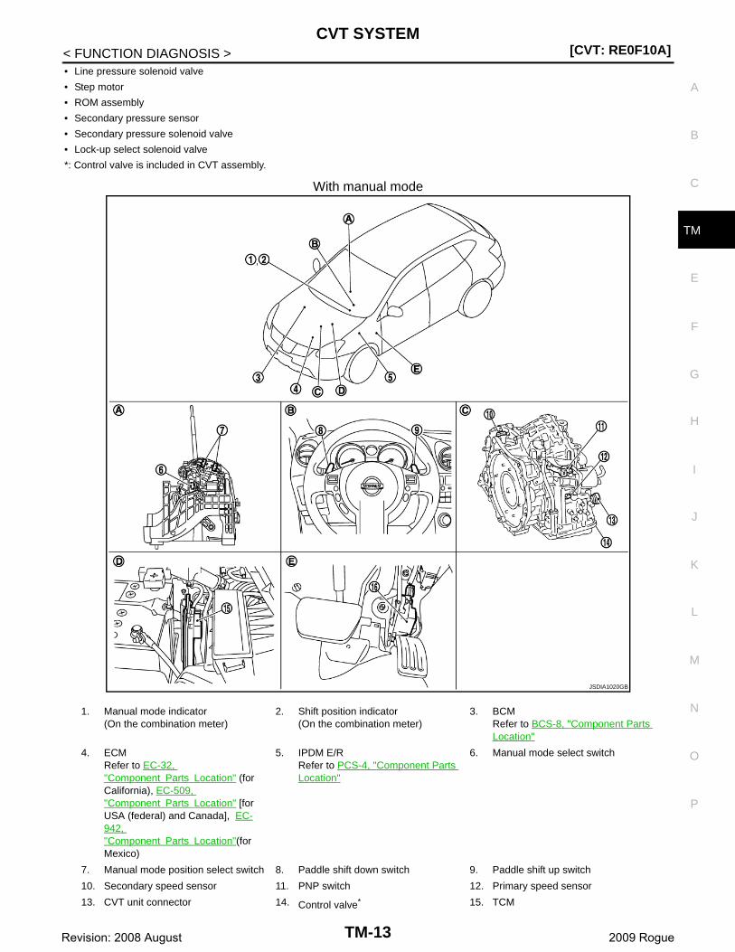
With manual mode
JSDIA1020GB
1. Manual mode indicator(On the combination meter)
2. Shift position indicator(On the combination meter)
3. BCMRefer to BCS-8, "Component Parts Location"
4. ECMRefer to EC-32, "Component Parts Location" (for California), EC-509, "Component Parts Location" [for USA (federal) and Canada], EC-942, "Component Parts Location"(for Mexico)
5. IPDM E/RRefer to PCS-4, "Component Parts Location"
6. Manual mode select switch
7. Manual mode position select switch 8. Paddle shift down switch 9. Paddle shift up switch
10. Secondary speed sensor 11. PNP switch 12. Primary speed sensor
13. CVT unit connector 14. Control valve* 15. TCM
TM-13Revision: 2008 August 2009 Rogue

[CVT: RE0F10A]CVT SYSTEM
< FUNCTION DIAGNOSIS >
NOTE:
The following components are included in control valve.
• CVT fluid temperature sensor
• Torque converter clutch solenoid valve
• Line pressure solenoid valve
• Step motor
• ROM assembly
• Secondary pressure sensor
• Secondary pressure solenoid valve
• Lock-up select solenoid valve
*: Control valve is included in CVT assembly.
16. Accelerator pedal position sensor
A. Control device B. Steering wheel C. Transaxle assembly
D. Engine room LH E. Accelerator pedal, upper
TM-14Revision: 2008 August 2009 Rogue

MECHANICAL SYSTEM[CVT: RE0F10A]
C
E
F
G
H
I
J
K
L
M
A
B
M
N
O
P
< FUNCTION DIAGNOSIS >
T
MECHANICAL SYSTEM
Cross-Sectional View INFOID:0000000004235359
1. Converter housing 2. Driven sprocket 3. Chain
4. Reverse brake 5. Oil pump 6. Forward clutch
7. Planetary carrier 8. Primary pulley 9. Sun gear
10. Steel belt 11. Side cover 12. Internal gear
13. Parking gear 14. Secondary pulley 15. Final gear
16. Differential case 17. Idler gear 18. Reduction gear
19. Taper roller bearing 20. Output gear 21. Drive sprocket
22. Input shaft 23. Torque converter 24. Drive trans gear
25. Ring trans gear
JSDIA1021ZZ
TM-15Revision: 2008 August 2009 Rogue
[CVT: RE0F10A]MECHANICAL SYSTEM
< FUNCTION DIAGNOSIS >
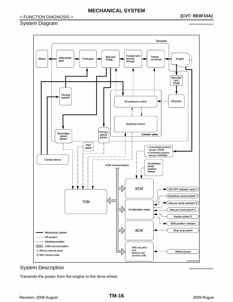
System Diagram INFOID:0000000004515029
System Description INFOID:0000000004235361
Transmits the power from the engine to the drive wheel.
JSDIA1059GB
TM-16Revision: 2008 August 2009 Rogue
MECHANICAL SYSTEM[CVT: RE0F10A]
C
E
F
G
H
I
J
K
L
M
A
B
M
N
O
P
< FUNCTION DIAGNOSIS >
T
Component Parts Location INFOID:0000000004490745
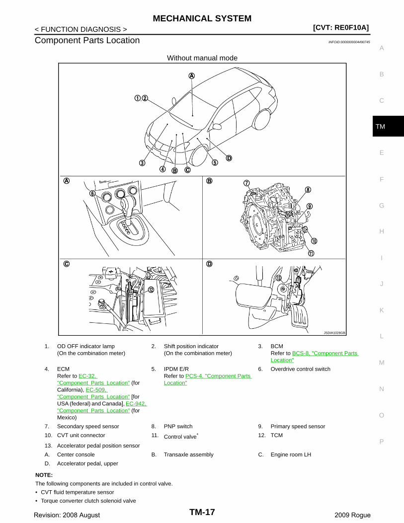
Without manual mode
NOTE:
The following components are included in control valve.
• CVT fluid temperature sensor
• Torque converter clutch solenoid valve
JSDIA1028GB
1. OD OFF indicator lamp(On the combination meter)
2. Shift position indicator(On the combination meter)
3. BCMRefer to BCS-8, "Component Parts Location"
4. ECMRefer to EC-32, "Component Parts Location" (for California), EC-509, "Component Parts Location" [for USA (federal) and Canada], EC-942, "Component Parts Location" (for Mexico)
5. IPDM E/RRefer to PCS-4, "Component Parts Location"
6. Overdrive control switch
7. Secondary speed sensor 8. PNP switch 9. Primary speed sensor
10. CVT unit connector 11. Control valve* 12. TCM
13. Accelerator pedal position sensor
A. Center console B. Transaxle assembly C. Engine room LH
D. Accelerator pedal, upper
TM-17Revision: 2008 August 2009 Rogue

[CVT: RE0F10A]MECHANICAL SYSTEM
< FUNCTION DIAGNOSIS >• Line pressure solenoid valve
• Step motor
• ROM assembly
• Secondary pressure sensor
• Secondary pressure solenoid valve
• Lock-up select solenoid valve
*: Control valve is included in CVT assembly.
With manual mode
JSDIA1020GB
1. Manual mode indicator(On the combination meter)
2. Shift position indicator(On the combination meter)
3. BCMRefer to BCS-8, "Component Parts Location"
4. ECMRefer to EC-32, "Component Parts Location" (for California), EC-509, "Component Parts Location" [for USA (federal) and Canada], EC-942, "Component Parts Location"(for Mexico)
5. IPDM E/RRefer to PCS-4, "Component Parts Location"
6. Manual mode select switch
7. Manual mode position select switch 8. Paddle shift down switch 9. Paddle shift up switch
10. Secondary speed sensor 11. PNP switch 12. Primary speed sensor
13. CVT unit connector 14. Control valve* 15. TCM
TM-18Revision: 2008 August 2009 Rogue
MECHANICAL SYSTEM[CVT: RE0F10A]
C
E
F
G
H
I
J
K
L
M
A
B
M
N
O
P
< FUNCTION DIAGNOSIS >
T
NOTE:
The following components are included in control valve.
• CVT fluid temperature sensor
• Torque converter clutch solenoid valve
• Line pressure solenoid valve
• Step motor
• ROM assembly
• Secondary pressure sensor
• Secondary pressure solenoid valve
• Lock-up select solenoid valve
*: Control valve is included in CVT assembly.
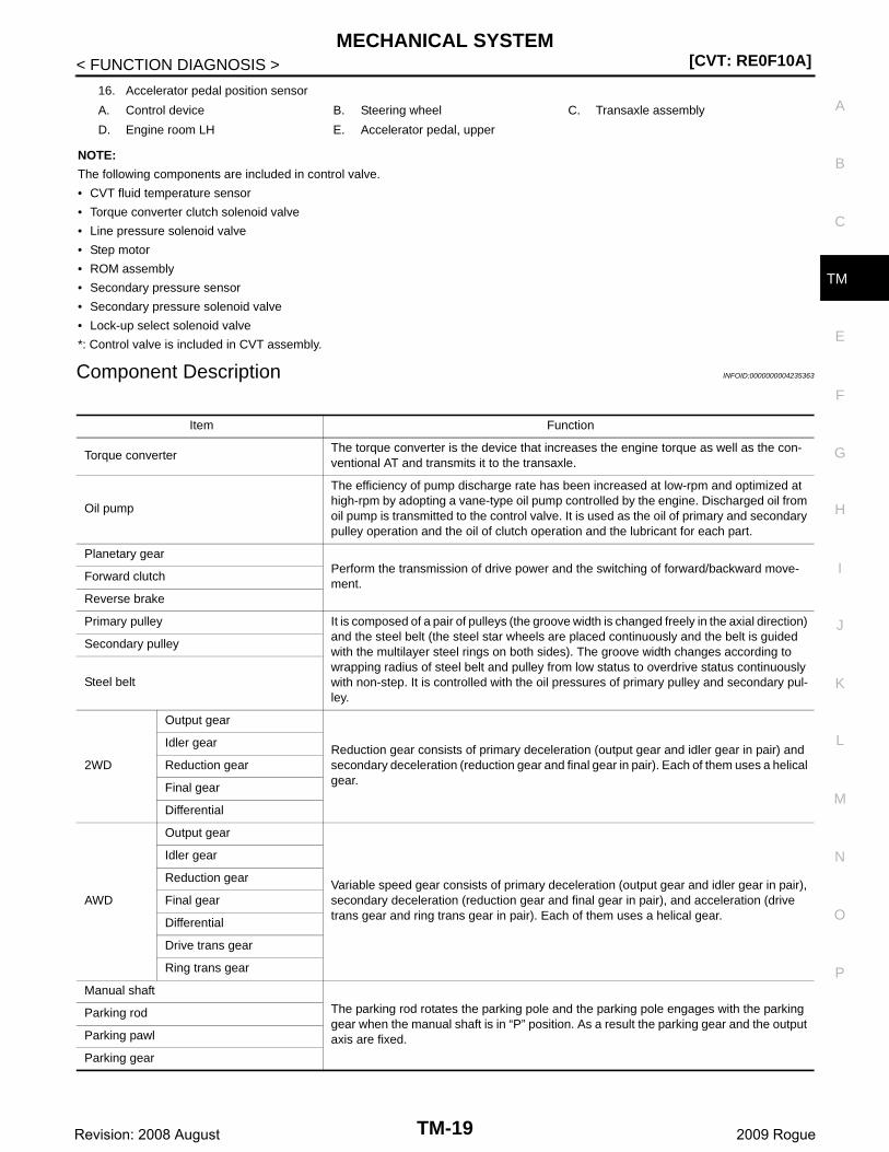
Component Description INFOID:0000000004235363
16. Accelerator pedal position sensor
A. Control device B. Steering wheel C. Transaxle assembly
D. Engine room LH E. Accelerator pedal, upper
Item Function
Torque converterThe torque converter is the device that increases the engine torque as well as the con-ventional AT and transmits it to the transaxle.
Oil pump
The efficiency of pump discharge rate has been increased at low-rpm and optimized at high-rpm by adopting a vane-type oil pump controlled by the engine. Discharged oil from oil pump is transmitted to the control valve. It is used as the oil of primary and secondary pulley operation and the oil of clutch operation and the lubricant for each part.
Planetary gearPerform the transmission of drive power and the switching of forward/backward move-ment.
Forward clutch
Reverse brake
Primary pulley It is composed of a pair of pulleys (the groove width is changed freely in the axial direction) and the steel belt (the steel star wheels are placed continuously and the belt is guided with the multilayer steel rings on both sides). The groove width changes according to wrapping radius of steel belt and pulley from low status to overdrive status continuously with non-step. It is controlled with the oil pressures of primary pulley and secondary pul-ley.
Secondary pulley
Steel belt
2WD
Output gear
Reduction gear consists of primary deceleration (output gear and idler gear in pair) and secondary deceleration (reduction gear and final gear in pair). Each of them uses a helical gear.
Idler gear
Reduction gear
Final gear
Differential
AWD
Output gear
Variable speed gear consists of primary deceleration (output gear and idler gear in pair), secondary deceleration (reduction gear and final gear in pair), and acceleration (drive trans gear and ring trans gear in pair). Each of them uses a helical gear.
Idler gear
Reduction gear
Final gear
Differential
Drive trans gear
Ring trans gear
Manual shaft
The parking rod rotates the parking pole and the parking pole engages with the parking gear when the manual shaft is in “P” position. As a result the parking gear and the output axis are fixed.
Parking rod
Parking pawl
Parking gear
TM-19Revision: 2008 August 2009 Rogue
[CVT: RE0F10A]HYDRAULIC CONTROL SYSTEM
< FUNCTION DIAGNOSIS >
HYDRAULIC CONTROL SYSTEM
System Diagram INFOID:0000000004235364
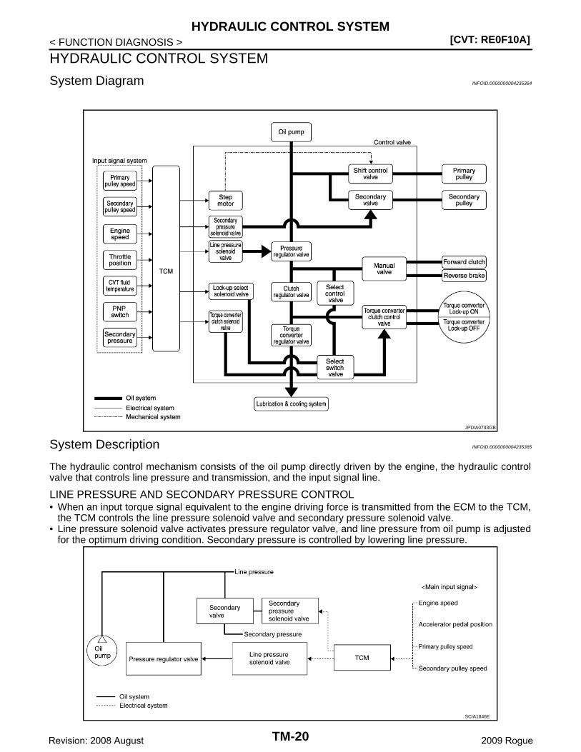
System Description INFOID:0000000004235365
The hydraulic control mechanism consists of the oil pump directly driven by the engine, the hydraulic controlvalve that controls line pressure and transmission, and the input signal line.
LINE PRESSURE AND SECONDARY PRESSURE CONTROL• When an input torque signal equivalent to the engine driving force is transmitted from the ECM to the TCM,
the TCM controls the line pressure solenoid valve and secondary pressure solenoid valve.• Line pressure solenoid valve activates pressure regulator valve, and line pressure from oil pump is adjusted
for the optimum driving condition. Secondary pressure is controlled by lowering line pressure.
JPDIA0733GB
SCIA1846E
TM-20Revision: 2008 August 2009 Rogue
HYDRAULIC CONTROL SYSTEM[CVT: RE0F10A]
C
E
F
G
H
I
J
K
L
M
A
B
M
N
O
P
< FUNCTION DIAGNOSIS >
T
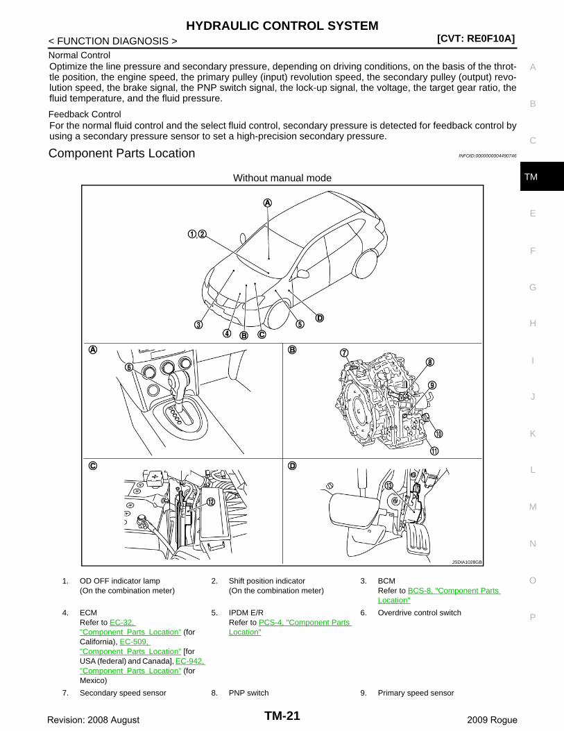
Normal ControlOptimize the line pressure and secondary pressure, depending on driving conditions, on the basis of the throt-tle position, the engine speed, the primary pulley (input) revolution speed, the secondary pulley (output) revo-lution speed, the brake signal, the PNP switch signal, the lock-up signal, the voltage, the target gear ratio, thefluid temperature, and the fluid pressure.
Feedback ControlFor the normal fluid control and the select fluid control, secondary pressure is detected for feedback control byusing a secondary pressure sensor to set a high-precision secondary pressure.
Component Parts Location INFOID:0000000004490746
Without manual mode
JSDIA1028GB
1. OD OFF indicator lamp(On the combination meter)
2. Shift position indicator(On the combination meter)
3. BCMRefer to BCS-8, "Component Parts Location"
4. ECMRefer to EC-32, "Component Parts Location" (for California), EC-509, "Component Parts Location" [for USA (federal) and Canada], EC-942, "Component Parts Location" (for Mexico)
5. IPDM E/RRefer to PCS-4, "Component Parts Location"
6. Overdrive control switch
7. Secondary speed sensor 8. PNP switch 9. Primary speed sensor
TM-21Revision: 2008 August 2009 Rogue
[CVT: RE0F10A]HYDRAULIC CONTROL SYSTEM
< FUNCTION DIAGNOSIS >
NOTE:
The following components are included in control valve.
• CVT fluid temperature sensor
• Torque converter clutch solenoid valve
• Line pressure solenoid valve
• Step motor
• ROM assembly
• Secondary pressure sensor
• Secondary pressure solenoid valve
• Lock-up select solenoid valve
*: Control valve is included in CVT assembly.
With manual mode
10. CVT unit connector 11. Control valve* 12. TCM
13. Accelerator pedal position sensor
A. Center console B. Transaxle assembly C. Engine room LH
D. Accelerator pedal, upper
JSDIA1020GB
TM-22Revision: 2008 August 2009 Rogue
HYDRAULIC CONTROL SYSTEM[CVT: RE0F10A]
C
E
F
G
H
I
J
K
L
M
A
B
M
N
O
P
< FUNCTION DIAGNOSIS >
T
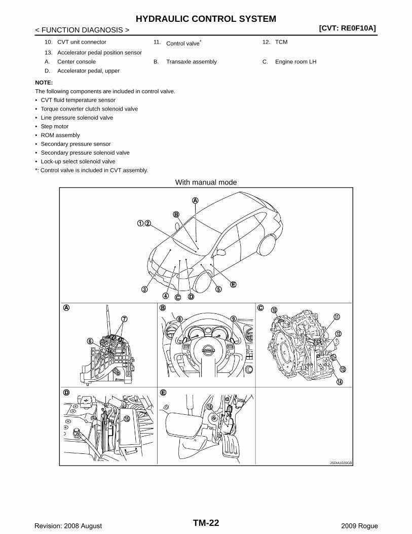
NOTE:
The following components are included in control valve.
• CVT fluid temperature sensor
• Torque converter clutch solenoid valve
• Line pressure solenoid valve
• Step motor
• ROM assembly
• Secondary pressure sensor
• Secondary pressure solenoid valve
• Lock-up select solenoid valve
*: Control valve is included in CVT assembly.
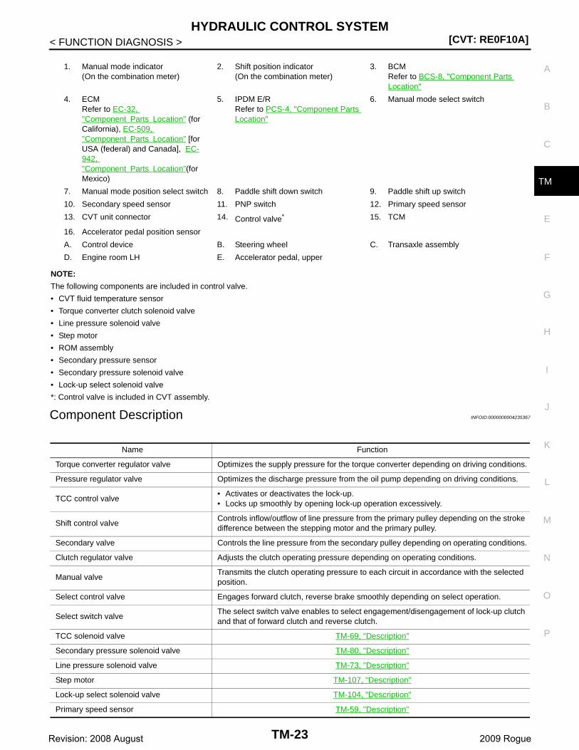
Component Description INFOID:0000000004235367
1. Manual mode indicator(On the combination meter)
2. Shift position indicator(On the combination meter)
3. BCMRefer to BCS-8, "Component Parts Location"
4. ECMRefer to EC-32, "Component Parts Location" (for California), EC-509, "Component Parts Location" [for USA (federal) and Canada], EC-942, "Component Parts Location"(for Mexico)
5. IPDM E/RRefer to PCS-4, "Component Parts Location"
6. Manual mode select switch
7. Manual mode position select switch 8. Paddle shift down switch 9. Paddle shift up switch
10. Secondary speed sensor 11. PNP switch 12. Primary speed sensor
13. CVT unit connector 14. Control valve* 15. TCM
16. Accelerator pedal position sensor
A. Control device B. Steering wheel C. Transaxle assembly
D. Engine room LH E. Accelerator pedal, upper
Name Function
Torque converter regulator valve Optimizes the supply pressure for the torque converter depending on driving conditions.
Pressure regulator valve Optimizes the discharge pressure from the oil pump depending on driving conditions.
TCC control valve• Activates or deactivates the lock-up.• Locks up smoothly by opening lock-up operation excessively.
Shift control valveControls inflow/outflow of line pressure from the primary pulley depending on the stroke difference between the stepping motor and the primary pulley.
Secondary valve Controls the line pressure from the secondary pulley depending on operating conditions.
Clutch regulator valve Adjusts the clutch operating pressure depending on operating conditions.
Manual valveTransmits the clutch operating pressure to each circuit in accordance with the selected position.
Select control valve Engages forward clutch, reverse brake smoothly depending on select operation.
Select switch valveThe select switch valve enables to select engagement/disengagement of lock-up clutch and that of forward clutch and reverse clutch.
TCC solenoid valve TM-69, "Description"
Secondary pressure solenoid valve TM-80, "Description"
Line pressure solenoid valve TM-73, "Description"
Step motor TM-107, "Description"
Lock-up select solenoid valve TM-104, "Description"
Primary speed sensor TM-59, "Description"
TM-23Revision: 2008 August 2009 Rogue
[CVT: RE0F10A]HYDRAULIC CONTROL SYSTEM
< FUNCTION DIAGNOSIS >
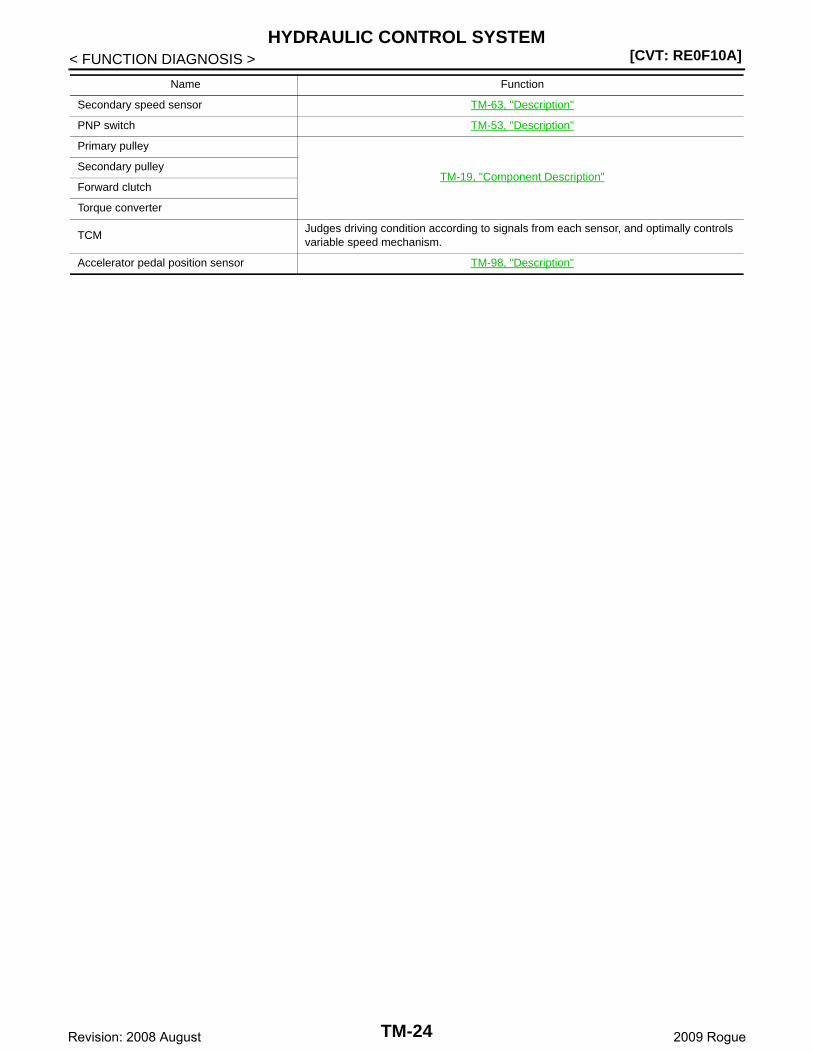
Secondary speed sensor TM-63, "Description"
PNP switch TM-53, "Description"
Primary pulley
TM-19, "Component Description"Secondary pulley
Forward clutch
Torque converter
TCMJudges driving condition according to signals from each sensor, and optimally controls variable speed mechanism.
Accelerator pedal position sensor TM-98, "Description"
Name Function
TM-24Revision: 2008 August 2009 Rogue

CONTROL SYSTEM[CVT: RE0F10A]
C
E
F
G
H
I
J
K
L
M
A
B
M
N
O
P
< FUNCTION DIAGNOSIS >
T
CONTROL SYSTEM
System Diagram INFOID:0000000004235368
System Description INFOID:0000000004235369
The CVT senses vehicle operating conditions through various sensors. It always controls the optimum shiftposition and reduces shifting and lock-up shocks.
TCM FUNCTION The function of the TCM is to:• Receive input signals sent from various switches and sensors.• Determine required line pressure, shifting point, and lock-up operation.• Send required output signals to the step motor and the respective solenoids.
• *1: Without manual mode
• *2: With manual mode
INPUT/OUTPUT SIGNAL OF TCM
JSDIA1060GB
SENSORS (or SIGNAL)
⇒
TCM
⇒
ACTUATORS
PNP switchAccelerator pedal position signalClosed throttle position signalEngine speed signalCVT fluid temperature sensorVehicle speed signal
Overdrive control switch signal*1
Manual mode signal*2
Paddle shifter signal*2
Stop lamp switch signalSecondary speed sensorSecondary pressure sensor
Shift controlLine pressure controlPrimary pressure controlSecondary pressure controlLock-up controlEngine brake controlVehicle speed controlFail-safe controlSelf-diagnosisCONSULT-III communication lineDuet-EA controlCAN systemOn board diagnosis
Step motor Torque converter clutch solenoid valveLock-up select solenoid valveLine pressure solenoid valveSecondary pressure solenoid valve
OD OFF indicator lamp*1
Manual mode indicator*2
Shift position indicator
TM-25Revision: 2008 August 2009 Rogue
[CVT: RE0F10A]CONTROL SYSTEM
< FUNCTION DIAGNOSIS >
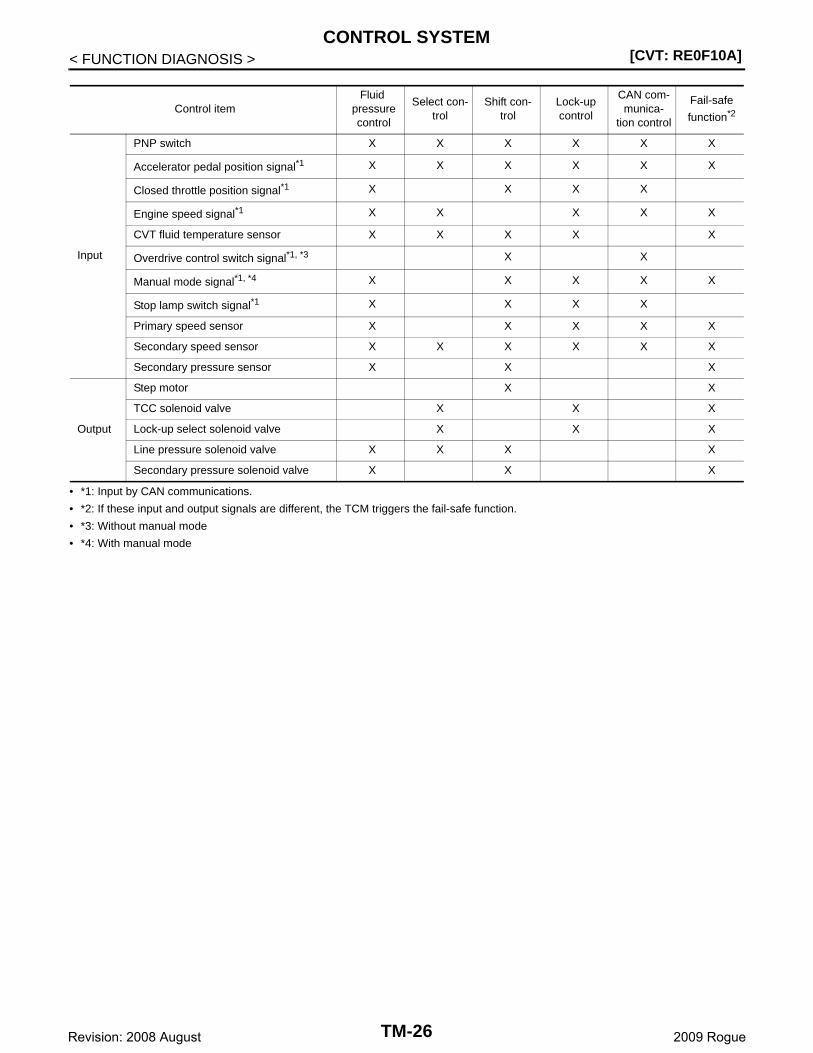
• *1: Input by CAN communications.
• *2: If these input and output signals are different, the TCM triggers the fail-safe function.
• *3: Without manual mode
• *4: With manual mode
Control itemFluid
pressure control
Select con-trol
Shift con-trol
Lock-up control
CAN com-munica-
tion control
Fail-safe
function*2
Input
PNP switch X X X X X X
Accelerator pedal position signal*1 X X X X X X
Closed throttle position signal*1 X X X X
Engine speed signal*1 X X X X X
CVT fluid temperature sensor X X X X X
Overdrive control switch signal*1, *3 X X
Manual mode signal*1, *4 X X X X X
Stop lamp switch signal*1 X X X X
Primary speed sensor X X X X X
Secondary speed sensor X X X X X X
Secondary pressure sensor X X X
Output
Step motor X X
TCC solenoid valve X X X
Lock-up select solenoid valve X X X
Line pressure solenoid valve X X X X
Secondary pressure solenoid valve X X X
TM-26Revision: 2008 August 2009 Rogue
CONTROL SYSTEM[CVT: RE0F10A]
C
E
F
G
H
I
J
K
L
M
A
B
M
N
O
P
< FUNCTION DIAGNOSIS >
T
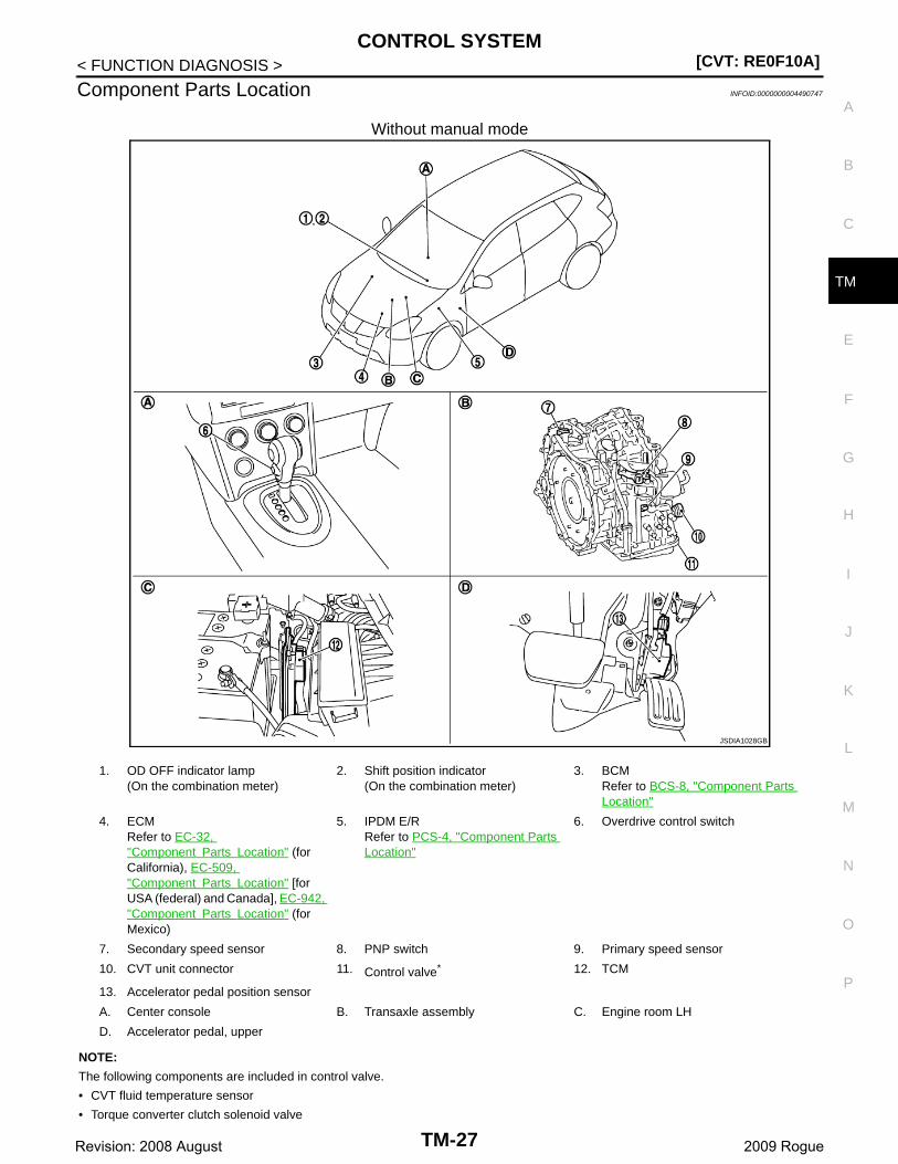
Component Parts Location INFOID:0000000004490747
Without manual mode
NOTE:
The following components are included in control valve.
• CVT fluid temperature sensor
• Torque converter clutch solenoid valve
JSDIA1028GB
1. OD OFF indicator lamp(On the combination meter)
2. Shift position indicator(On the combination meter)
3. BCMRefer to BCS-8, "Component Parts Location"
4. ECMRefer to EC-32, "Component Parts Location" (for California), EC-509, "Component Parts Location" [for USA (federal) and Canada], EC-942, "Component Parts Location" (for Mexico)
5. IPDM E/RRefer to PCS-4, "Component Parts Location"
6. Overdrive control switch
7. Secondary speed sensor 8. PNP switch 9. Primary speed sensor
10. CVT unit connector 11. Control valve* 12. TCM
13. Accelerator pedal position sensor
A. Center console B. Transaxle assembly C. Engine room LH
D. Accelerator pedal, upper
TM-27Revision: 2008 August 2009 Rogue

[CVT: RE0F10A]CONTROL SYSTEM
< FUNCTION DIAGNOSIS >• Line pressure solenoid valve
• Step motor
• ROM assembly
• Secondary pressure sensor
• Secondary pressure solenoid valve
• Lock-up select solenoid valve
*: Control valve is included in CVT assembly.
With manual mode
JSDIA1020GB
1. Manual mode indicator(On the combination meter)
2. Shift position indicator(On the combination meter)
3. BCMRefer to BCS-8, "Component Parts Location"
4. ECMRefer to EC-32, "Component Parts Location" (for California), EC-509, "Component Parts Location" [for USA (federal) and Canada], EC-942, "Component Parts Location"(for Mexico)
5. IPDM E/RRefer to PCS-4, "Component Parts Location"
6. Manual mode select switch
7. Manual mode position select switch 8. Paddle shift down switch 9. Paddle shift up switch
10. Secondary speed sensor 11. PNP switch 12. Primary speed sensor
13. CVT unit connector 14. Control valve* 15. TCM
TM-28Revision: 2008 August 2009 Rogue
CONTROL SYSTEM[CVT: RE0F10A]
C
E
F
G
H
I
J
K
L
M
A
B
M
N
O
P
< FUNCTION DIAGNOSIS >
T
NOTE:
The following components are included in control valve.
• CVT fluid temperature sensor
• Torque converter clutch solenoid valve
• Line pressure solenoid valve
• Step motor
• ROM assembly
• Secondary pressure sensor
• Secondary pressure solenoid valve
• Lock-up select solenoid valve
*: Control valve is included in CVT assembly.
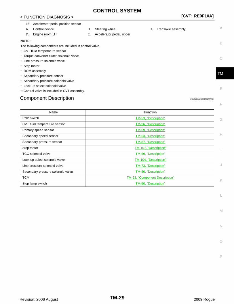
Component Description INFOID:0000000004235371
16. Accelerator pedal position sensor
A. Control device B. Steering wheel C. Transaxle assembly
D. Engine room LH E. Accelerator pedal, upper
Name Function
PNP switch TM-53, "Description"
CVT fluid temperature sensor TM-56, "Description"
Primary speed sensor TM-59, "Description"
Secondary speed sensor TM-63, "Description"
Secondary pressure sensor TM-87, "Description"
Step motor TM-107, "Description"
TCC solenoid valve TM-69, "Description"
Lock-up select solenoid valve TM-104, "Description"
Line pressure solenoid valve TM-73, "Description"
Secondary pressure solenoid valve TM-80, "Description"
TCM TM-23, "Component Description"
Stop lamp switch TM-50, "Description"
TM-29Revision: 2008 August 2009 Rogue

[CVT: RE0F10A]LOCK-UP AND SELECT CONTROL SYSTEM
< FUNCTION DIAGNOSIS >
LOCK-UP AND SELECT CONTROL SYSTEM
System Diagram INFOID:0000000004235372
System Description INFOID:0000000004235373
• The torque converter clutch piston in the torque converter is engaged to eliminate torque converter slip toincrease power transmission efficiency.
• The torque converter clutch control valve operation is controlled by the torque converter clutch solenoidvalve, which is controlled by a signal from TCM. The torque converter clutch control valve engages orreleases the torque converter clutch piston.
• When shifting between “N” (“P”) ⇔“D” (“R”), torque converter clutch solenoid valve controls engagementpower of forward clutch and reverse brake.
• The lock-up applied gear range was expanded by locking up thetorque converter at a lower vehicle speed than conventional CVTmodels.
TORQUE CONVERTER CLUTCH AND SELECT CONTROL VALVE CONTROL
Lock-up Released In the lock-up released state, the torque converter clutch control valve is set into the unlocked state by thetorque converter clutch solenoid valve and the lock-up apply pressure is drained.In this way, the torque converter clutch piston is not coupled.
Lock-up AppliedIn the lock-up applied state, the torque converter clutch control valve is set into the locked state by the torqueconverter clutch solenoid valve and lock-up apply pressure is generated.In this way, the torque converter clutch piston is pressed and coupled.
Select ControlWhen shifting between “N” (“P”) ⇔“D” (“R”), optimize the operating pressure on the basis of the throttle posi-tion, the engine speed, and the secondary pulley (output) revolution speed to lessen the shift shock.
SCIA2374E
JPDIA0312GB
TM-30Revision: 2008 August 2009 Rogue

LOCK-UP AND SELECT CONTROL SYSTEM[CVT: RE0F10A]
C
E
F
G
H
I
J
K
L
M
A
B
M
N
O
P
< FUNCTION DIAGNOSIS >
T
Component Parts Location INFOID:0000000004490748
Without manual mode
NOTE:
The following components are included in control valve.
• CVT fluid temperature sensor
• Torque converter clutch solenoid valve
JSDIA1028GB
1. OD OFF indicator lamp(On the combination meter)
2. Shift position indicator(On the combination meter)
3. BCMRefer to BCS-8, "Component Parts Location"
4. ECMRefer to EC-32, "Component Parts Location" (for California), EC-509, "Component Parts Location" [for USA (federal) and Canada], EC-942, "Component Parts Location" (for Mexico)
5. IPDM E/RRefer to PCS-4, "Component Parts Location"
6. Overdrive control switch
7. Secondary speed sensor 8. PNP switch 9. Primary speed sensor
10. CVT unit connector 11. Control valve* 12. TCM
13. Accelerator pedal position sensor
A. Center console B. Transaxle assembly C. Engine room LH
D. Accelerator pedal, upper
TM-31Revision: 2008 August 2009 Rogue
[CVT: RE0F10A]LOCK-UP AND SELECT CONTROL SYSTEM
< FUNCTION DIAGNOSIS >• Line pressure solenoid valve
• Step motor
• ROM assembly
• Secondary pressure sensor
• Secondary pressure solenoid valve
• Lock-up select solenoid valve
*: Control valve is included in CVT assembly.
With manual mode
JSDIA1020GB
1. Manual mode indicator(On the combination meter)
2. Shift position indicator(On the combination meter)
3. BCMRefer to BCS-8, "Component Parts Location"
4. ECMRefer to EC-32, "Component Parts Location" (for California), EC-509, "Component Parts Location" [for USA (federal) and Canada], EC-942, "Component Parts Location"(for Mexico)
5. IPDM E/RRefer to PCS-4, "Component Parts Location"
6. Manual mode select switch
7. Manual mode position select switch 8. Paddle shift down switch 9. Paddle shift up switch
10. Secondary speed sensor 11. PNP switch 12. Primary speed sensor
13. CVT unit connector 14. Control valve* 15. TCM
TM-32Revision: 2008 August 2009 Rogue

LOCK-UP AND SELECT CONTROL SYSTEM[CVT: RE0F10A]
C
E
F
G
H
I
J
K
L
M
A
B
M
N
O
P
< FUNCTION DIAGNOSIS >
T
NOTE:
The following components are included in control valve.
• CVT fluid temperature sensor
• Torque converter clutch solenoid valve
• Line pressure solenoid valve
• Step motor
• ROM assembly
• Secondary pressure sensor
• Secondary pressure solenoid valve
• Lock-up select solenoid valve
*: Control valve is included in CVT assembly.
Component Description INFOID:0000000004235375
16. Accelerator pedal position sensor
A. Control device B. Steering wheel C. Transaxle assembly
D. Engine room LH E. Accelerator pedal, upper
Name Function
Torque converter regulator valve
TM-23, "Component Description"
TCC control valve
Select control valve
Select switch valve
Manual valve
TCC solenoid valve TM-69, "Description"
Lock-up select solenoid valve TM-104, "Description"
Primary speed sensor TM-59, "Description"
Secondary speed sensor TM-63, "Description"
CVT fluid temperature sensor TM-56, "Description"
PNP switch TM-53, "Description"
Forward clutch
TM-19, "Component Description"Reverse brake
Torque converter
TCMJudges driving condition according to signals from each sensor, and optimally controls variable speed mechanism.
Accelerator pedal position sensor TM-98, "Description"
TM-33Revision: 2008 August 2009 Rogue
[CVT: RE0F10A]SHIFT CONTROL SYSTEM
< FUNCTION DIAGNOSIS >
SHIFT CONTROL SYSTEM
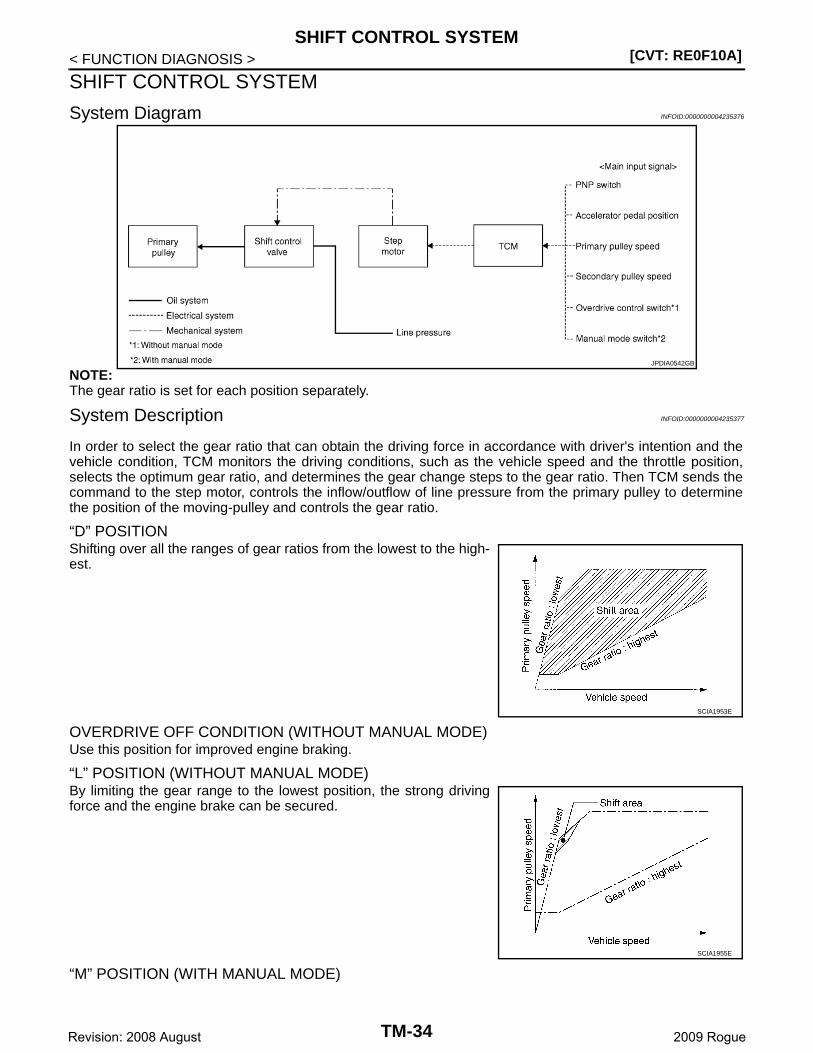
System Diagram INFOID:0000000004235376
NOTE:The gear ratio is set for each position separately.
System Description INFOID:0000000004235377
In order to select the gear ratio that can obtain the driving force in accordance with driver's intention and thevehicle condition, TCM monitors the driving conditions, such as the vehicle speed and the throttle position,selects the optimum gear ratio, and determines the gear change steps to the gear ratio. Then TCM sends thecommand to the step motor, controls the inflow/outflow of line pressure from the primary pulley to determinethe position of the moving-pulley and controls the gear ratio.
“D” POSITIONShifting over all the ranges of gear ratios from the lowest to the high-est.
OVERDRIVE OFF CONDITION (WITHOUT MANUAL MODE)Use this position for improved engine braking.
“L” POSITION (WITHOUT MANUAL MODE)By limiting the gear range to the lowest position, the strong drivingforce and the engine brake can be secured.
“M” POSITION (WITH MANUAL MODE)
JPDIA0542GB
SCIA1953E
SCIA1955E
TM-34Revision: 2008 August 2009 Rogue
SHIFT CONTROL SYSTEM[CVT: RE0F10A]
C
E
F
G
H
I
J
K
L
M
A
B
M
N
O
P
< FUNCTION DIAGNOSIS >
T
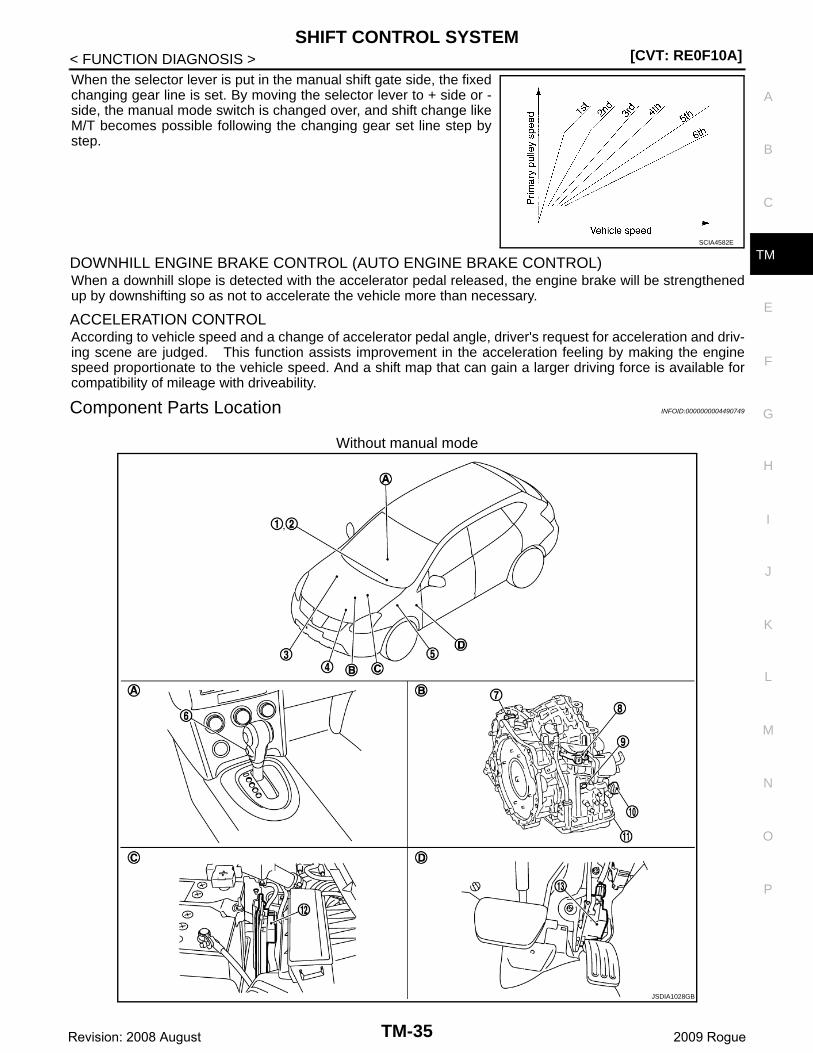
When the selector lever is put in the manual shift gate side, the fixedchanging gear line is set. By moving the selector lever to + side or -side, the manual mode switch is changed over, and shift change likeM/T becomes possible following the changing gear set line step bystep.
DOWNHILL ENGINE BRAKE CONTROL (AUTO ENGINE BRAKE CONTROL)When a downhill slope is detected with the accelerator pedal released, the engine brake will be strengthenedup by downshifting so as not to accelerate the vehicle more than necessary.
ACCELERATION CONTROLAccording to vehicle speed and a change of accelerator pedal angle, driver's request for acceleration and driv-ing scene are judged. This function assists improvement in the acceleration feeling by making the enginespeed proportionate to the vehicle speed. And a shift map that can gain a larger driving force is available forcompatibility of mileage with driveability.
Component Parts Location INFOID:0000000004490749
Without manual mode
SCIA4582E
JSDIA1028GB
TM-35Revision: 2008 August 2009 Rogue
[CVT: RE0F10A]SHIFT CONTROL SYSTEM
< FUNCTION DIAGNOSIS >
NOTE:
The following components are included in control valve.
• CVT fluid temperature sensor
• Torque converter clutch solenoid valve
• Line pressure solenoid valve
• Step motor
• ROM assembly
• Secondary pressure sensor
• Secondary pressure solenoid valve
• Lock-up select solenoid valve
*: Control valve is included in CVT assembly.
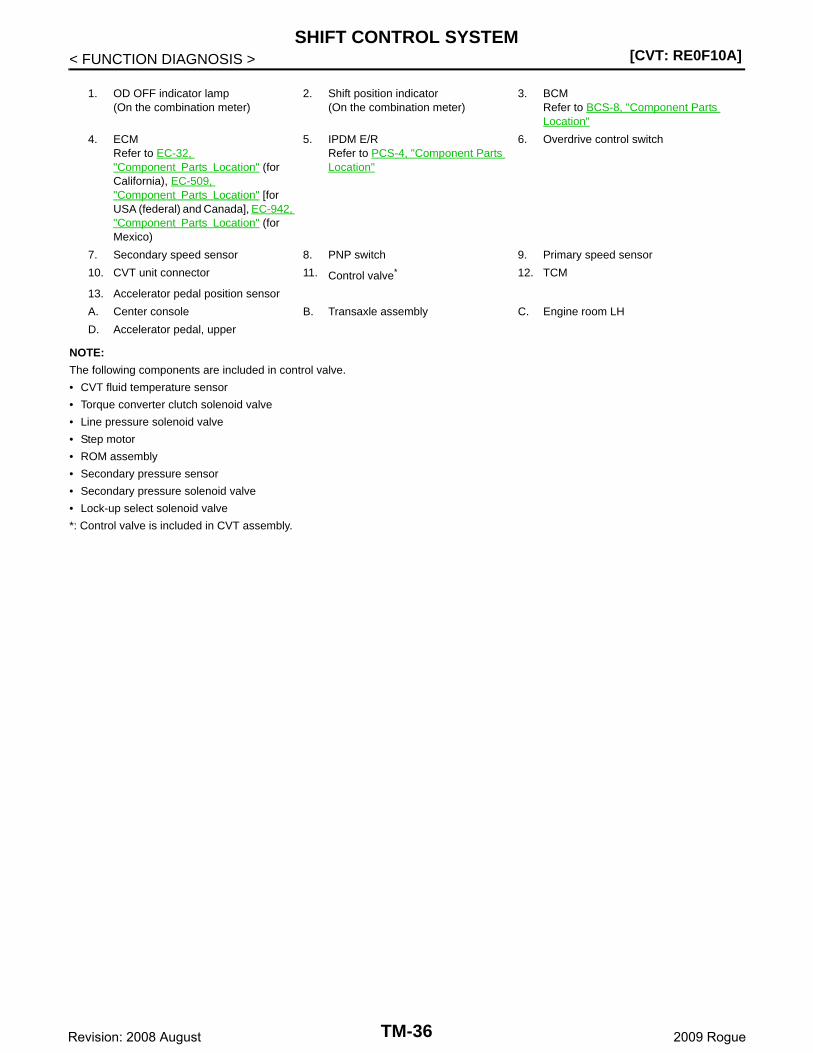
1. OD OFF indicator lamp(On the combination meter)
2. Shift position indicator(On the combination meter)
3. BCMRefer to BCS-8, "Component Parts Location"
4. ECMRefer to EC-32, "Component Parts Location" (for California), EC-509, "Component Parts Location" [for USA (federal) and Canada], EC-942, "Component Parts Location" (for Mexico)
5. IPDM E/RRefer to PCS-4, "Component Parts Location"
6. Overdrive control switch
7. Secondary speed sensor 8. PNP switch 9. Primary speed sensor
10. CVT unit connector 11. Control valve* 12. TCM
13. Accelerator pedal position sensor
A. Center console B. Transaxle assembly C. Engine room LH
D. Accelerator pedal, upper
TM-36Revision: 2008 August 2009 Rogue
SHIFT CONTROL SYSTEM[CVT: RE0F10A]
C
E
F
G
H
I
J
K
L
M
A
B
M
N
O
P
< FUNCTION DIAGNOSIS >
T
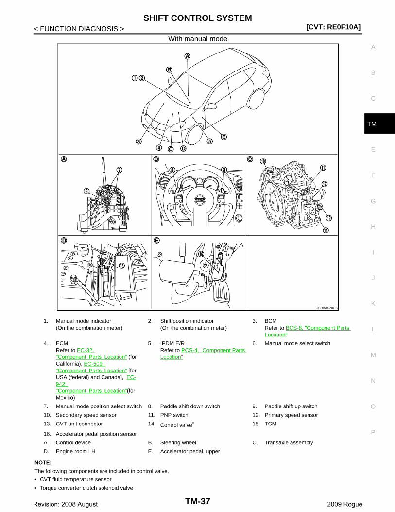
With manual mode
NOTE:
The following components are included in control valve.
• CVT fluid temperature sensor
• Torque converter clutch solenoid valve
JSDIA1020GB
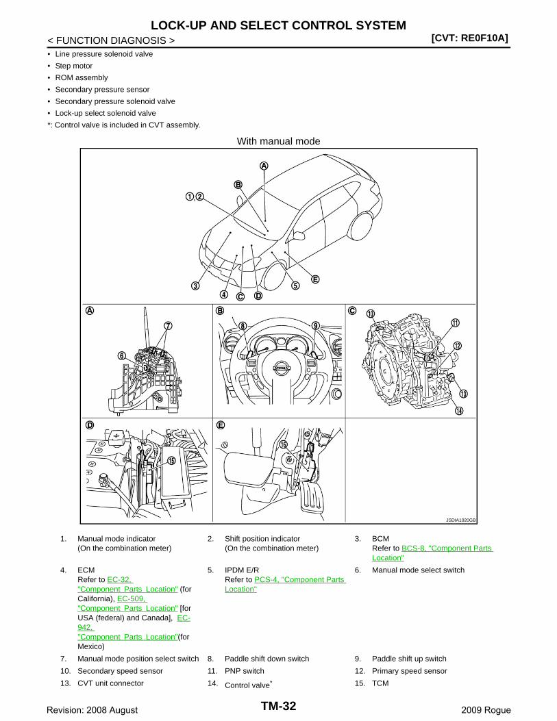
1. Manual mode indicator(On the combination meter)
2. Shift position indicator(On the combination meter)
3. BCMRefer to BCS-8, "Component Parts Location"
4. ECMRefer to EC-32, "Component Parts Location" (for California), EC-509, "Component Parts Location" [for USA (federal) and Canada], EC-942, "Component Parts Location"(for Mexico)
5. IPDM E/RRefer to PCS-4, "Component Parts Location"
6. Manual mode select switch
7. Manual mode position select switch 8. Paddle shift down switch 9. Paddle shift up switch
10. Secondary speed sensor 11. PNP switch 12. Primary speed sensor
13. CVT unit connector 14. Control valve* 15. TCM
16. Accelerator pedal position sensor
A. Control device B. Steering wheel C. Transaxle assembly
D. Engine room LH E. Accelerator pedal, upper
TM-37Revision: 2008 August 2009 Rogue
[CVT: RE0F10A]SHIFT CONTROL SYSTEM
< FUNCTION DIAGNOSIS >• Line pressure solenoid valve
• Step motor
• ROM assembly
• Secondary pressure sensor
• Secondary pressure solenoid valve
• Lock-up select solenoid valve
*: Control valve is included in CVT assembly.
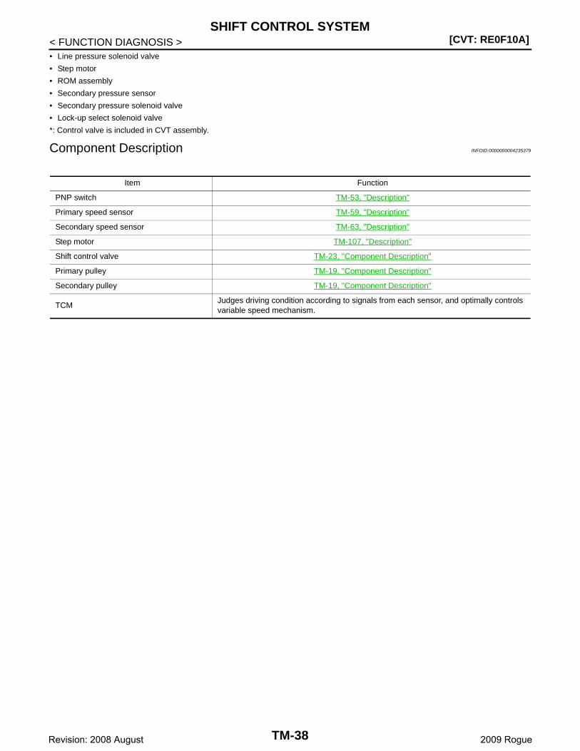
Component Description INFOID:0000000004235379
Item Function
PNP switch TM-53, "Description"
Primary speed sensor TM-59, "Description"
Secondary speed sensor TM-63, "Description"
Step motor TM-107, "Description"
Shift control valve TM-23, "Component Description"
Primary pulley TM-19, "Component Description"
Secondary pulley TM-19, "Component Description"
TCMJudges driving condition according to signals from each sensor, and optimally controls variable speed mechanism.
TM-38Revision: 2008 August 2009 Rogue
SHIFT LOCK SYSTEM[CVT: RE0F10A]
C
E
F
G
H
I
J
K
L
M
A
B
M
N
O
P
< FUNCTION DIAGNOSIS >
T
SHIFT LOCK SYSTEM
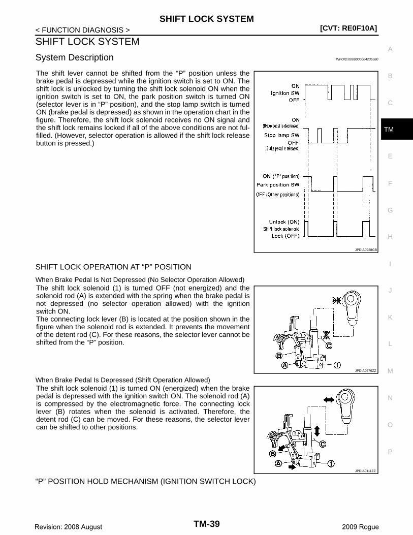
System Description INFOID:0000000004235380
The shift lever cannot be shifted from the “P” position unless thebrake pedal is depressed while the ignition switch is set to ON. Theshift lock is unlocked by turning the shift lock solenoid ON when theignition switch is set to ON, the park position switch is turned ON(selector lever is in “P” position), and the stop lamp switch is turnedON (brake pedal is depressed) as shown in the operation chart in thefigure. Therefore, the shift lock solenoid receives no ON signal andthe shift lock remains locked if all of the above conditions are not ful-filled. (However, selector operation is allowed if the shift lock releasebutton is pressed.)
SHIFT LOCK OPERATION AT “P” POSITION
When Brake Pedal Is Not Depressed (No Selector Operation Allowed)The shift lock solenoid (1) is turned OFF (not energized) and thesolenoid rod (A) is extended with the spring when the brake pedal isnot depressed (no selector operation allowed) with the ignitionswitch ON.The connecting lock lever (B) is located at the position shown in thefigure when the solenoid rod is extended. It prevents the movementof the detent rod (C). For these reasons, the selector lever cannot beshifted from the “P” position.
When Brake Pedal Is Depressed (Shift Operation Allowed)The shift lock solenoid (1) is turned ON (energized) when the brakepedal is depressed with the ignition switch ON. The solenoid rod (A)is compressed by the electromagnetic force. The connecting locklever (B) rotates when the solenoid is activated. Therefore, thedetent rod (C) can be moved. For these reasons, the selector levercan be shifted to other positions.
“P” POSITION HOLD MECHANISM (IGNITION SWITCH LOCK)
JPDIA0928GB
JPDIA0576ZZ
JPDIA0111ZZ
TM-39Revision: 2008 August 2009 Rogue
[CVT: RE0F10A]SHIFT LOCK SYSTEM
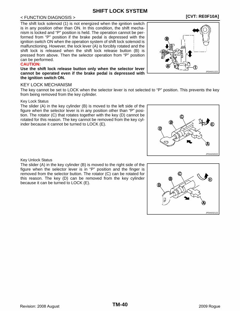
< FUNCTION DIAGNOSIS >The shift lock solenoid (1) is not energized when the ignition switchis in any position other than ON. In this condition, the shift mecha-nism is locked and “P” position is held. The operation cannot be per-formed from “P” position if the brake pedal is depressed with theignition switch ON when the operation system of shift lock solenoid ismalfunctioning. However, the lock lever (A) is forcibly rotated and theshift lock is released when the shift lock release button (B) ispressed from above. Then the selector operation from “P” positioncan be performed.CAUTION:Use the shift lock release button only when the selector levercannot be operated even if the brake pedal is depressed withthe ignition switch ON.
KEY LOCK MECHANISMThe key cannot be set to LOCK when the selector lever is not selected to “P” position. This prevents the keyfrom being removed from the key cylinder.
Key Lock StatusThe slider (A) in the key cylinder (B) is moved to the left side of thefigure when the selector lever is in any position other than “P” posi-tion. The rotator (C) that rotates together with the key (D) cannot berotated for this reason. The key cannot be removed from the key cyl-inder because it cannot be turned to LOCK (E).
Key Unlock StatusThe slider (A) in the key cylinder (B) is moved to the right side of thefigure when the selector lever is in “P” position and the finger isremoved from the selector button. The rotator (C) can be rotated forthis reason. The key (D) can be removed from the key cylinderbecause it can be turned to LOCK (E).
JPDIA0112ZZ
JPDIA0320ZZ
JPDIA0321ZZ
TM-40Revision: 2008 August 2009 Rogue
SHIFT LOCK SYSTEM[CVT: RE0F10A]
C
E
F
G
H
I
J
K
L
M
A
B
M
N
O
P
< FUNCTION DIAGNOSIS >
T
Component Parts Location INFOID:0000000004235381
Component Description INFOID:0000000004235382
SHIFT LOCK
KEY LOCK
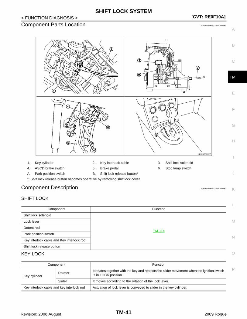
1. Key cylinder 2. Key interlock cable 3. Shift lock solenoid
4. ASCD brake switch 5. Brake pedal 6. Stop lamp switch
A. Park position switch B. Shift lock release button*
*: Shift lock release button becomes operative by removing shift lock cover.
JPDIA0532ZZ
Component Function
Shift lock solenoid
TM-114
Lock lever
Detent rod
Park position switch
Key interlock cable and Key interlock rod
Shift lock release button
Component Function
Key cylinderRotator
It rotates together with the key and restricts the slider movement when the ignition switch is in LOCK position.
Slider It moves according to the rotation of the lock lever.
Key interlock cable and key interlock rod Actuation of lock lever is conveyed to slider in the key cylinder.
TM-41Revision: 2008 August 2009 Rogue
[CVT: RE0F10A]ON BOARD DIAGNOSTIC (OBD) SYSTEM
< FUNCTION DIAGNOSIS >
ON BOARD DIAGNOSTIC (OBD) SYSTEM
Diagnosis Description INFOID:0000000004235383
DESCRIPTIONThe CVT system has two self-diagnostic systems.The first is the emission-related on board diagnostic system (OBD-II) performed by the TCM in combinationwith the ECM. A malfunction is indicated by the MIL (Malfunction Indicator Lamp) and is stored as a DTC inthe ECM memory and in the TCM memory.The second is the TCM original self-diagnosis performed by the TCM. A malfunction history is stored in theTCM memory. The detected items are overlapped with OBD-II self-diagnostic items. For details, refer to TM-133, "DTC Index".
OBD-II FUNCTIONThe ECM provides emission-related on board diagnostic (OBD-II) functions for the CVT system. One functionis to receive a signal from the TCM used with OBD-related parts of the CVT system. The signal is sent to theECM when a malfunction occurs in the corresponding OBD-related part. The other function is to indicate adiagnostic result by means of the MIL (Malfunction Indicator Lamp) on the instrument panel. Sensors,switches and solenoid valves are used as sensing elements.The MIL automatically illuminates in “One or Two Trip Detection Logic” when a malfunction is sensed in rela-tion to CVT system parts.
ONE OR TWO TRIP DETECTION LOGIC OF OBD-II
One Trip Detection LogicIf a malfunction is sensed during the first test drive, the MIL illuminates and the ECM memory stores the mal-function as a DTC. The TCM is not provided with such a memory function.
Two Trip Detection LogicWhen a malfunction is sensed during the first test drive, it is stored in the ECM memory as a 1st trip DTC(diagnostic trouble code) or 1st trip freeze frame data. At this point, the MIL does not illuminate. — 1st tripIf the same malfunction as that experienced during the first test drive is sensed during the second test drive,the MIL will illuminate. — 2nd tripThe “trip” in the “One or Two Trip Detection Logic” means a driving mode in which self-diagnosis is performedduring vehicle operation.
OBD-II DIAGNOSTIC TROUBLE CODE (DTC)
How to Read DTC and 1st Trip DTCDTC and 1st trip DTC can be read by the following methods.( With CONSULT-III or GST) CONSULT-III or GST (Generic Scan Tool) Examples: P0705, P0720, etc.These DTC are prescribed by SAE J2012.(CONSULT-III also displays the malfunctioning component or system.)• 1st trip DTC No. is the same as DTC No.• Output of the diagnostic trouble code indicates that the indicated circuit has a malfunction. How-
ever, in case of the Mode II and GST, they do not indicate whether the malfunction is still occurring orit occurred in the past and has returned to normal.CONSULT-III can identify them as shown below, therefore, CONSULT-III (if available) is recom-mended.
- DTC or 1st trip DTC of a malfunction is displayed in “Self Diagnostic Results” in “ENGINE” with CONSULT-III. Time data indicates how many times the vehicle was driven after the last detection of a DTC.
- If the DTC is being detected currently, the time data will be “0”.- If a 1st trip DTC is stored in the ECM, the time data will be “1t”.
Freeze Frame Data and 1st Trip Freeze Frame Data• The ECM has a memory function, which stores the driving conditions such as fuel system status, calculated
load value, engine coolant temperature, short-term fuel trim, long-term fuel trim, engine speed and vehiclespeed at the moment the ECM detects a malfunction.Data that are stored in the ECM memory, along with the 1st trip DTC, are called 1st trip freeze frame data,and the data, stored together with the DTC data, are called freeze frame data and displayed on CONSULT-III or GST. The 1st trip freeze frame data can only be displayed on the CONSULT-III screen, not on the GST.For details, refer to EC-105, "CONSULT-III Function" (for California), EC-576, "CONSULT-III Function" [forUSA (Federal) and Canada], EC-1003, "CONSULT-III Function" (for Mexico).
TM-42Revision: 2008 August 2009 Rogue
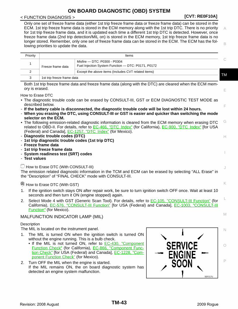
ON BOARD DIAGNOSTIC (OBD) SYSTEM[CVT: RE0F10A]
C
E
F
G
H
I
J
K
L
M
A
B
M
N
O
P
< FUNCTION DIAGNOSIS >
T
Only one set of freeze frame data (either 1st trip freeze frame data or freeze frame data) can be stored in theECM. 1st trip freeze frame data is stored in the ECM memory along with the 1st trip DTC. There is no priorityfor 1st trip freeze frame data, and it is updated each time a different 1st trip DTC is detected. However, oncefreeze frame data (2nd trip detection/MIL on) is stored in the ECM memory, 1st trip freeze frame data is nolonger stored. Remember, only one set of freeze frame data can be stored in the ECM. The ECM has the fol-lowing priorities to update the data.
Both 1st trip freeze frame data and freeze frame data (along with the DTC) are cleared when the ECM mem-ory is erased.
How to Erase DTC• The diagnostic trouble code can be erased by CONSULT-III, GST or ECM DIAGNOSTIC TEST MODE as
described below.- If the battery cable is disconnected, the diagnostic trouble code will be lost within 24 hours.- When you erasing the DTC, using CONSULT-III or GST is easier and quicker than switching the mode
selector on the ECM.• The following emission-related diagnostic information is cleared from the ECM memory when erasing DTC
related to OBD-II. For details, refer to EC-466, "DTC Index" (for California), EC-900, "DTC Index" [for USA(Federal) and Canada], EC-1257, "DTC Index" (for Mexico).
- Diagnostic trouble codes (DTC)- 1st trip diagnostic trouble codes (1st trip DTC)- Freeze frame data- 1st trip freeze frame data- System readiness test (SRT) codes- Test values
How to Erase DTC (With CONSULT-III)The emission related diagnostic information in the TCM and ECM can be erased by selecting “ALL Erase” inthe “Description” of “FINAL CHECK” mode with CONSULT-III.
How to Erase DTC (With GST)
1. If the ignition switch stays ON after repair work, be sure to turn ignition switch OFF once. Wait at least 10seconds and then turn it ON (engine stopped) again.
2. Select Mode 4 with GST (Generic Scan Tool). For details, refer to EC-105, "CONSULT-III Function" (forCalifornia), EC-576, "CONSULT-III Function" [for USA (Federal) and Canada], EC-1003, "CONSULT-IIIFunction" (for Mexico).
MALFUNCTION INDICATOR LAMP (MIL)
DescriptionThe MIL is located on the instrument panel.1. The MIL is turned ON when the ignition switch is turned ON
without the engine running. This is a bulb check.• If the MIL is not turned ON, refer to EC-430, "Component
Function Check" (for California), EC-866, "Component Func-tion Check" [for USA (Federal) and Canada], EC-1228, "Com-ponent Function Check" (for Mexico).
2. Turn OFF the MIL when the engine is started.If the MIL remains ON, the on board diagnostic system hasdetected an engine system malfunction.
Priority Items
1Freeze frame data
Misfire — DTC: P0300 - P0304Fuel Injection System Function — DTC: P0171, P0172
2 Except the above items (Includes CVT related items)
3 1st trip freeze frame data
SEF217U
TM-43Revision: 2008 August 2009 Rogue
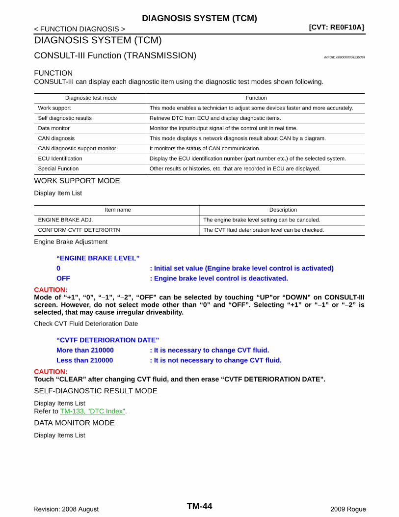
[CVT: RE0F10A]DIAGNOSIS SYSTEM (TCM)
< FUNCTION DIAGNOSIS >
DIAGNOSIS SYSTEM (TCM)
CONSULT-III Function (TRANSMISSION) INFOID:0000000004235384
FUNCTIONCONSULT-III can display each diagnostic item using the diagnostic test modes shown following.
WORK SUPPORT MODE
Display Item List
Engine Brake Adjustment
CAUTION:Mode of “+1”, “0”, “−1”, “−2”, “OFF” can be selected by touching “UP”or “DOWN” on CONSULT-IIIscreen. However, do not select mode other than “0” and “OFF”. Selecting “+1” or “−1” or “−2” isselected, that may cause irregular driveability.
Check CVT Fluid Deterioration Date
CAUTION:Touch “CLEAR” after changing CVT fluid, and then erase “CVTF DETERIORATION DATE”.
SELF-DIAGNOSTIC RESULT MODE
Display Items ListRefer to TM-133, "DTC Index".
DATA MONITOR MODE
Display Items List
Diagnostic test mode Function
Work support This mode enables a technician to adjust some devices faster and more accurately.
Self diagnostic results Retrieve DTC from ECU and display diagnostic items.
Data monitor Monitor the input/output signal of the control unit in real time.
CAN diagnosis This mode displays a network diagnosis result about CAN by a diagram.
CAN diagnostic support monitor It monitors the status of CAN communication.
ECU Identification Display the ECU identification number (part number etc.) of the selected system.
Special Function Other results or histories, etc. that are recorded in ECU are displayed.
Item name Description
ENGINE BRAKE ADJ. The engine brake level setting can be canceled.
CONFORM CVTF DETERIORTN The CVT fluid deterioration level can be checked.
“ENGINE BRAKE LEVEL”0 : Initial set value (Engine brake level control is activated)OFF : Engine brake level control is deactivated.
“CVTF DETERIORATION DATE”More than 210000 : It is necessary to change CVT fluid.Less than 210000 : It is not necessary to change CVT fluid.
TM-44Revision: 2008 August 2009 Rogue
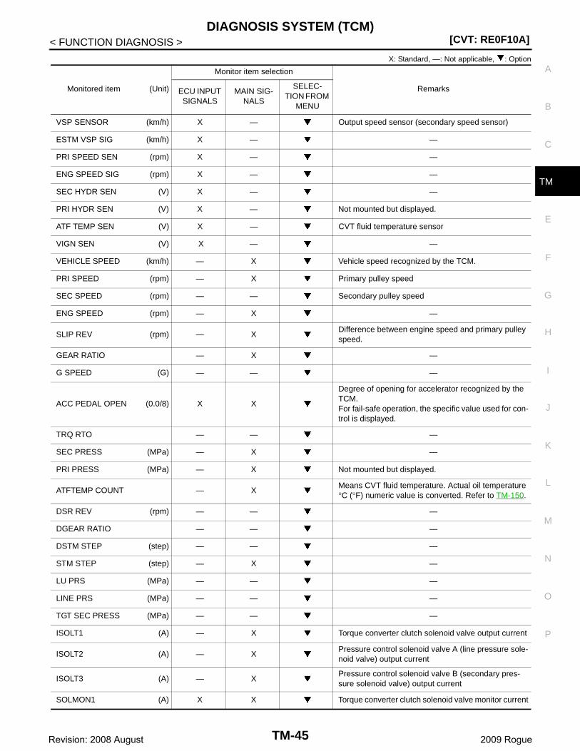
DIAGNOSIS SYSTEM (TCM)[CVT: RE0F10A]
C
E
F
G
H
I
J
K
L
M
A
B
M
N
O
P
< FUNCTION DIAGNOSIS >
T
X: Standard, —: Not applicable, : Option
Monitored item (Unit)
Monitor item selection
RemarksECU INPUT SIGNALS
MAIN SIG-NALS
SELEC-TION FROM
MENU
VSP SENSOR (km/h) X — Output speed sensor (secondary speed sensor)
ESTM VSP SIG (km/h) X — —
PRI SPEED SEN (rpm) X — —
ENG SPEED SIG (rpm) X — —
SEC HYDR SEN (V) X — —
PRI HYDR SEN (V) X — Not mounted but displayed.
ATF TEMP SEN (V) X — CVT fluid temperature sensor
VIGN SEN (V) X — —
VEHICLE SPEED (km/h) — X Vehicle speed recognized by the TCM.
PRI SPEED (rpm) — X Primary pulley speed
SEC SPEED (rpm) — — Secondary pulley speed
ENG SPEED (rpm) — X —
SLIP REV (rpm) — XDifference between engine speed and primary pulley speed.
GEAR RATIO — X —
G SPEED (G) — — —
ACC PEDAL OPEN (0.0/8) X X
Degree of opening for accelerator recognized by the TCM.For fail-safe operation, the specific value used for con-trol is displayed.
TRQ RTO — — —
SEC PRESS (MPa) — X —
PRI PRESS (MPa) — X Not mounted but displayed.
ATFTEMP COUNT — XMeans CVT fluid temperature. Actual oil temperature °C (°F) numeric value is converted. Refer to TM-150.
DSR REV (rpm) — — —
DGEAR RATIO — — —
DSTM STEP (step) — — —
STM STEP (step) — X —
LU PRS (MPa) — — —
LINE PRS (MPa) — — —
TGT SEC PRESS (MPa) — — —
ISOLT1 (A) — X Torque converter clutch solenoid valve output current
ISOLT2 (A) — XPressure control solenoid valve A (line pressure sole-noid valve) output current
ISOLT3 (A) — XPressure control solenoid valve B (secondary pres-sure solenoid valve) output current
SOLMON1 (A) X X Torque converter clutch solenoid valve monitor current
TM-45Revision: 2008 August 2009 Rogue
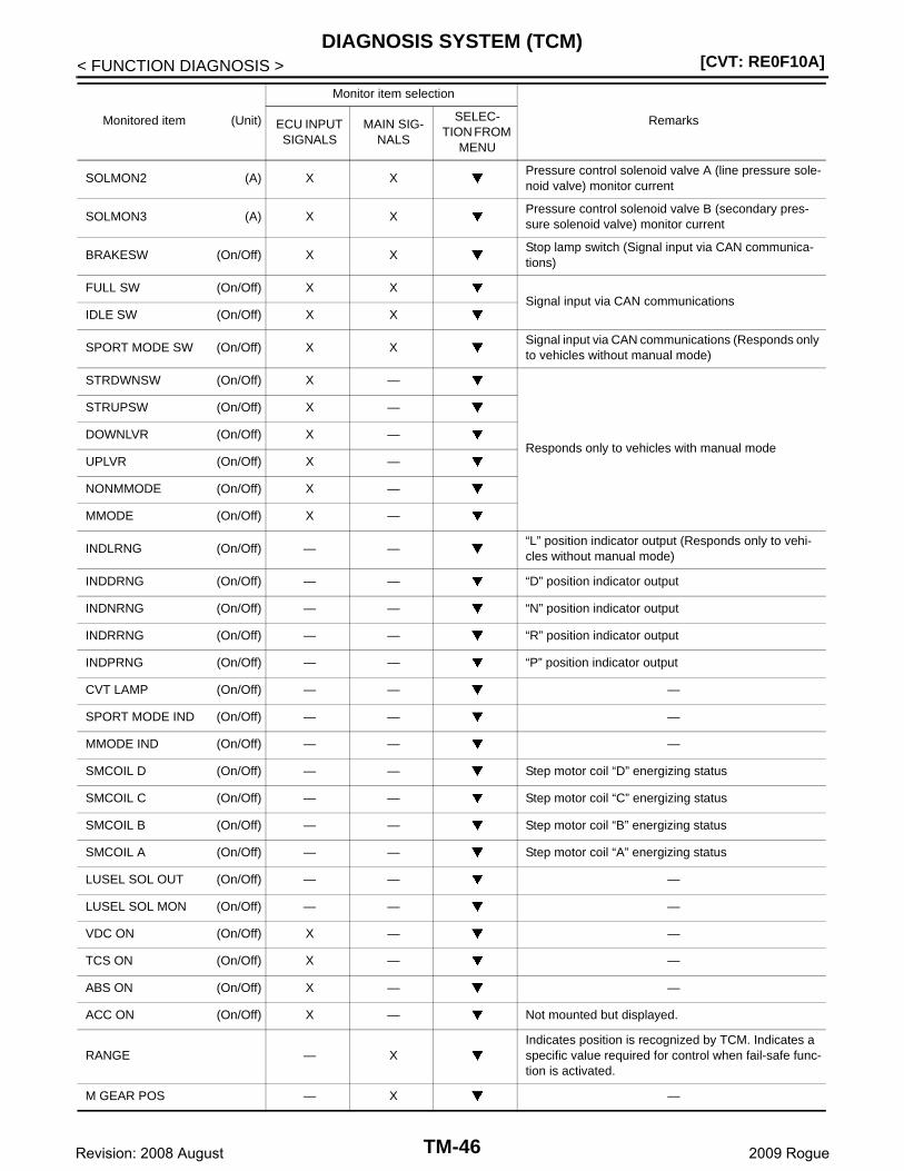
[CVT: RE0F10A]DIAGNOSIS SYSTEM (TCM)
< FUNCTION DIAGNOSIS >
SOLMON2 (A) X XPressure control solenoid valve A (line pressure sole-noid valve) monitor current
SOLMON3 (A) X XPressure control solenoid valve B (secondary pres-sure solenoid valve) monitor current
BRAKESW (On/Off) X XStop lamp switch (Signal input via CAN communica-tions)
FULL SW (On/Off) X XSignal input via CAN communications
IDLE SW (On/Off) X X
SPORT MODE SW (On/Off) X XSignal input via CAN communications (Responds only to vehicles without manual mode)
STRDWNSW (On/Off) X —
Responds only to vehicles with manual mode
STRUPSW (On/Off) X —
DOWNLVR (On/Off) X —
UPLVR (On/Off) X —
NONMMODE (On/Off) X —
MMODE (On/Off) X —
INDLRNG (On/Off) — —“L” position indicator output (Responds only to vehi-cles without manual mode)
INDDRNG (On/Off) — — “D” position indicator output
INDNRNG (On/Off) — — “N” position indicator output
INDRRNG (On/Off) — — “R” position indicator output
INDPRNG (On/Off) — — “P” position indicator output
CVT LAMP (On/Off) — — —
SPORT MODE IND (On/Off) — — —
MMODE IND (On/Off) — — —
SMCOIL D (On/Off) — — Step motor coil “D” energizing status
SMCOIL C (On/Off) — — Step motor coil “C” energizing status
SMCOIL B (On/Off) — — Step motor coil “B” energizing status
SMCOIL A (On/Off) — — Step motor coil “A” energizing status
LUSEL SOL OUT (On/Off) — — —
LUSEL SOL MON (On/Off) — — —
VDC ON (On/Off) X — —
TCS ON (On/Off) X — —
ABS ON (On/Off) X — —
ACC ON (On/Off) X — Not mounted but displayed.
RANGE — XIndicates position is recognized by TCM. Indicates a specific value required for control when fail-safe func-tion is activated.
M GEAR POS — X —
Monitored item (Unit)
Monitor item selection
RemarksECU INPUT SIGNALS
MAIN SIG-NALS
SELEC-TION FROM
MENU
TM-46Revision: 2008 August 2009 Rogue
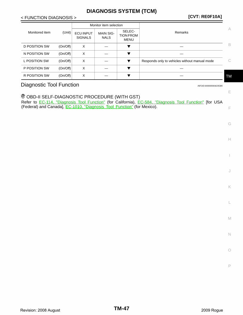
DIAGNOSIS SYSTEM (TCM)[CVT: RE0F10A]
C
E
F
G
H
I
J
K
L
M
A
B
M
N
O
P
< FUNCTION DIAGNOSIS >
T
Diagnostic Tool Function INFOID:0000000004235385
OBD-II SELF-DIAGNOSTIC PROCEDURE (WITH GST)Refer to EC-114, "Diagnosis Tool Function" (for California), EC-584, "Diagnosis Tool Function" [for USA(Federal) and Canada], EC-1010, "Diagnosis Tool Function" (for Mexico).
D POSITION SW (On/Off) X — —
N POSITION SW (On/Off) X — —
L POSITION SW (On/Off) X — Responds only to vehicles without manual mode
P POSITION SW (On/Off) X — —
R POSITION SW (On/Off) X — —
Monitored item (Unit)
Monitor item selection
RemarksECU INPUT SIGNALS
MAIN SIG-NALS
SELEC-TION FROM
MENU
TM-47Revision: 2008 August 2009 Rogue
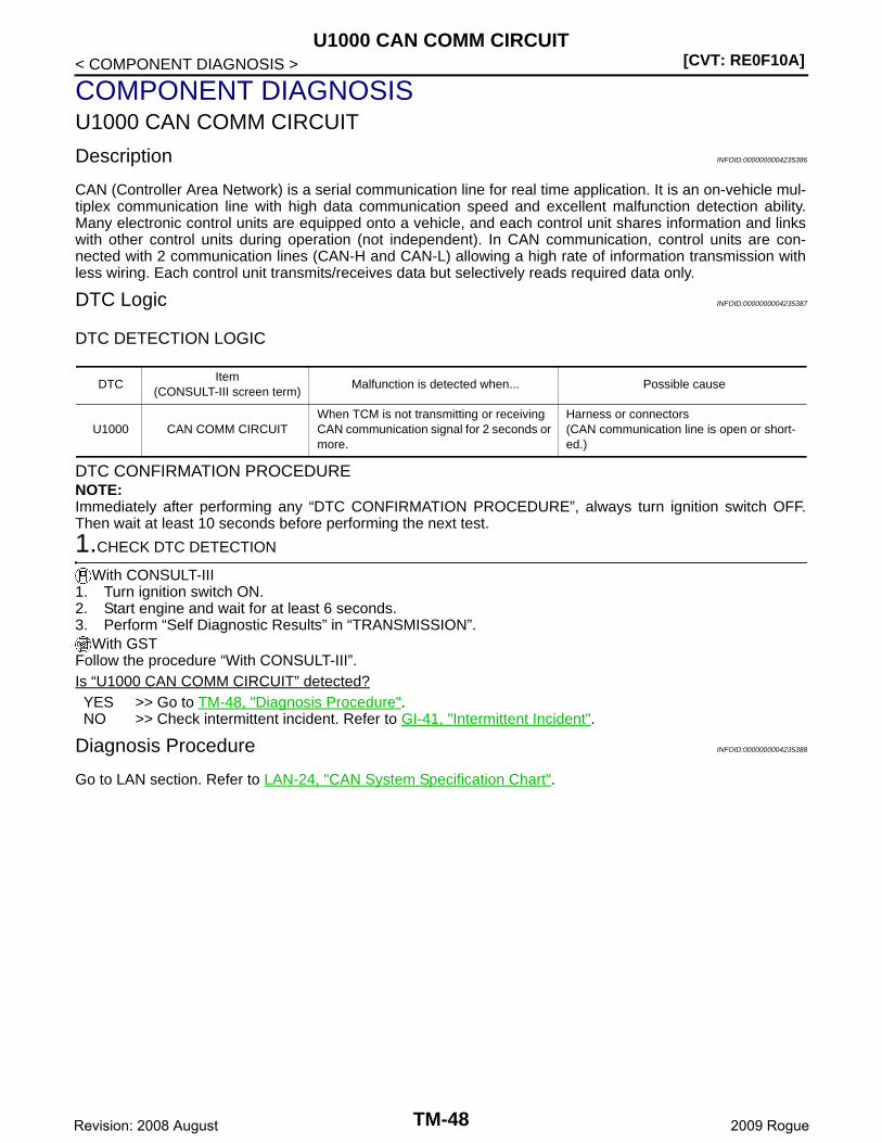
[CVT: RE0F10A]U1000 CAN COMM CIRCUIT
< COMPONENT DIAGNOSIS >
COMPONENT DIAGNOSISU1000 CAN COMM CIRCUIT
Description INFOID:0000000004235386
CAN (Controller Area Network) is a serial communication line for real time application. It is an on-vehicle mul-tiplex communication line with high data communication speed and excellent malfunction detection ability.Many electronic control units are equipped onto a vehicle, and each control unit shares information and linkswith other control units during operation (not independent). In CAN communication, control units are con-nected with 2 communication lines (CAN-H and CAN-L) allowing a high rate of information transmission withless wiring. Each control unit transmits/receives data but selectively reads required data only.
DTC Logic INFOID:0000000004235387
DTC DETECTION LOGIC
DTC CONFIRMATION PROCEDURENOTE:Immediately after performing any “DTC CONFIRMATION PROCEDURE”, always turn ignition switch OFF.Then wait at least 10 seconds before performing the next test.
1.CHECK DTC DETECTION
With CONSULT-III1. Turn ignition switch ON.2. Start engine and wait for at least 6 seconds.3. Perform “Self Diagnostic Results” in “TRANSMISSION”.
With GSTFollow the procedure “With CONSULT-III”.Is “U1000 CAN COMM CIRCUIT” detected?YES >> Go to TM-48, "Diagnosis Procedure".NO >> Check intermittent incident. Refer to GI-41, "Intermittent Incident".
Diagnosis Procedure INFOID:0000000004235388
Go to LAN section. Refer to LAN-24, "CAN System Specification Chart".
DTCItem
(CONSULT-III screen term)Malfunction is detected when... Possible cause
U1000 CAN COMM CIRCUITWhen TCM is not transmitting or receiving CAN communication signal for 2 seconds or more.
Harness or connectors(CAN communication line is open or short-ed.)
TM-48Revision: 2008 August 2009 Rogue
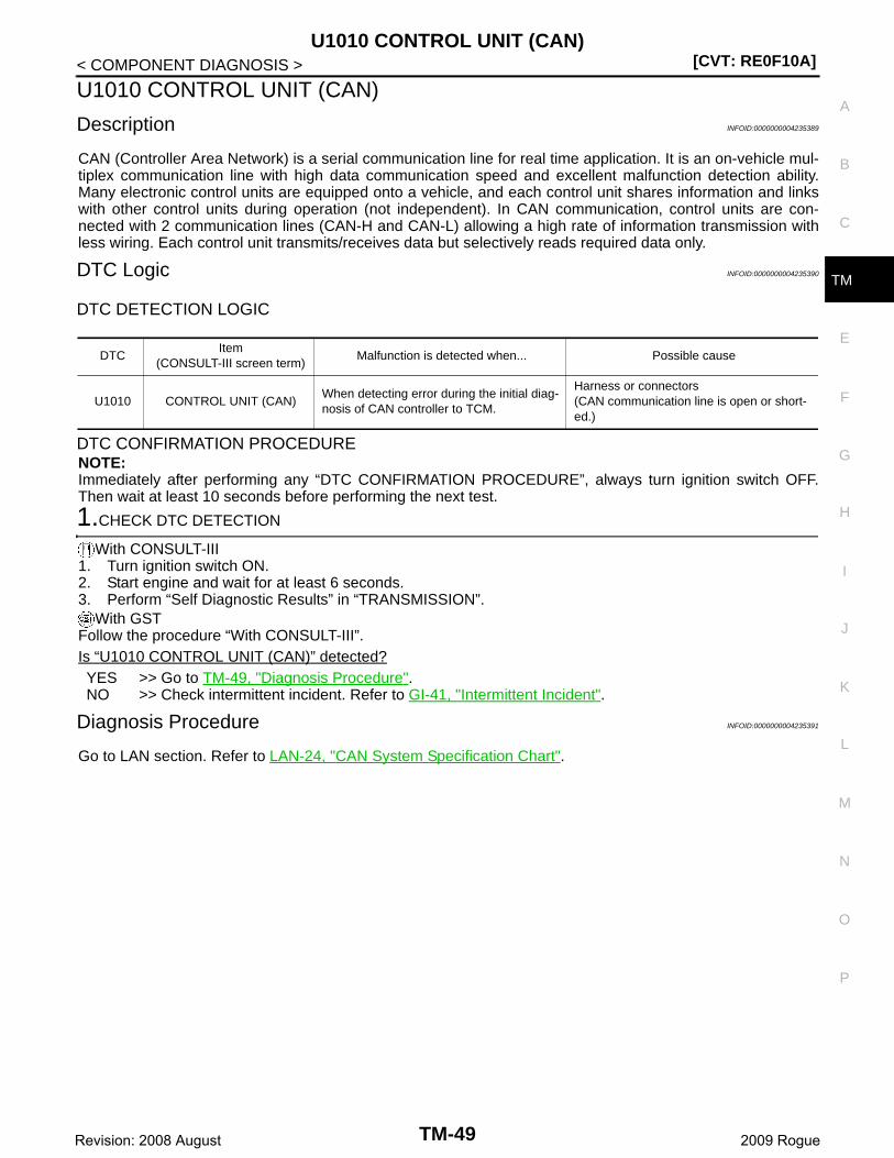
U1010 CONTROL UNIT (CAN)[CVT: RE0F10A]
C
E
F
G
H
I
J
K
L
M
A
B
M
N
O
P
< COMPONENT DIAGNOSIS >
T
U1010 CONTROL UNIT (CAN)
Description INFOID:0000000004235389
CAN (Controller Area Network) is a serial communication line for real time application. It is an on-vehicle mul-tiplex communication line with high data communication speed and excellent malfunction detection ability.Many electronic control units are equipped onto a vehicle, and each control unit shares information and linkswith other control units during operation (not independent). In CAN communication, control units are con-nected with 2 communication lines (CAN-H and CAN-L) allowing a high rate of information transmission withless wiring. Each control unit transmits/receives data but selectively reads required data only.
DTC Logic INFOID:0000000004235390
DTC DETECTION LOGIC
DTC CONFIRMATION PROCEDURENOTE:Immediately after performing any “DTC CONFIRMATION PROCEDURE”, always turn ignition switch OFF.Then wait at least 10 seconds before performing the next test.
1.CHECK DTC DETECTION
With CONSULT-III1. Turn ignition switch ON.2. Start engine and wait for at least 6 seconds.3. Perform “Self Diagnostic Results” in “TRANSMISSION”.
With GSTFollow the procedure “With CONSULT-III”.Is “U1010 CONTROL UNIT (CAN)” detected?YES >> Go to TM-49, "Diagnosis Procedure".NO >> Check intermittent incident. Refer to GI-41, "Intermittent Incident".
Diagnosis Procedure INFOID:0000000004235391
Go to LAN section. Refer to LAN-24, "CAN System Specification Chart".
DTCItem
(CONSULT-III screen term)Malfunction is detected when... Possible cause
U1010 CONTROL UNIT (CAN)When detecting error during the initial diag-nosis of CAN controller to TCM.
Harness or connectors(CAN communication line is open or short-ed.)
TM-49Revision: 2008 August 2009 Rogue
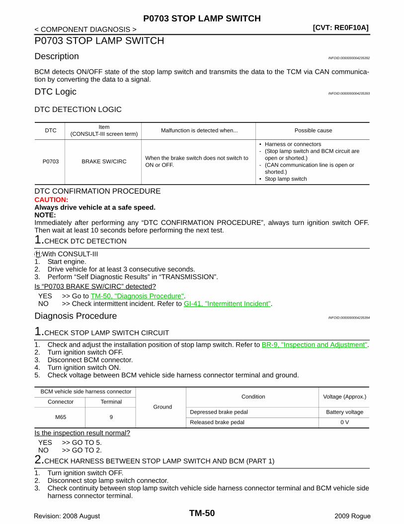
[CVT: RE0F10A]P0703 STOP LAMP SWITCH
< COMPONENT DIAGNOSIS >
P0703 STOP LAMP SWITCH
Description INFOID:0000000004235392
BCM detects ON/OFF state of the stop lamp switch and transmits the data to the TCM via CAN communica-tion by converting the data to a signal.
DTC Logic INFOID:0000000004235393
DTC DETECTION LOGIC
DTC CONFIRMATION PROCEDURECAUTION:Always drive vehicle at a safe speed.NOTE:Immediately after performing any “DTC CONFIRMATION PROCEDURE”, always turn ignition switch OFF.Then wait at least 10 seconds before performing the next test.
1.CHECK DTC DETECTION
With CONSULT-III1. Start engine.2. Drive vehicle for at least 3 consecutive seconds.3. Perform “Self Diagnostic Results” in “TRANSMISSION”.Is “P0703 BRAKE SW/CIRC” detected?YES >> Go to TM-50, "Diagnosis Procedure".NO >> Check intermittent incident. Refer to GI-41, "Intermittent Incident".
Diagnosis Procedure INFOID:0000000004235394
1.CHECK STOP LAMP SWITCH CIRCUIT
1. Check and adjust the installation position of stop lamp switch. Refer to BR-9, "Inspection and Adjustment".2. Turn ignition switch OFF.3. Disconnect BCM connector.4. Turn ignition switch ON.5. Check voltage between BCM vehicle side harness connector terminal and ground.
Is the inspection result normal?YES >> GO TO 5.NO >> GO TO 2.
2.CHECK HARNESS BETWEEN STOP LAMP SWITCH AND BCM (PART 1)
1. Turn ignition switch OFF.2. Disconnect stop lamp switch connector.3. Check continuity between stop lamp switch vehicle side harness connector terminal and BCM vehicle side
harness connector terminal.
DTCItem
(CONSULT-III screen term)Malfunction is detected when... Possible cause
P0703 BRAKE SW/CIRCWhen the brake switch does not switch to ON or OFF.
• Harness or connectors- (Stop lamp switch and BCM circuit are
open or shorted.)- (CAN communication line is open or
shorted.)• Stop lamp switch
BCM vehicle side harness connector
Ground
Condition Voltage (Approx.)Connector Terminal
M65 9Depressed brake pedal Battery voltage
Released brake pedal 0 V
TM-50Revision: 2008 August 2009 Rogue

P0703 STOP LAMP SWITCH[CVT: RE0F10A]
C
E
F
G
H
I
J
K
L
M
A
B
M
N
O
P
< COMPONENT DIAGNOSIS >
T
Is the inspection result normal?YES >> GO TO 3.NO >> Repair or replace damaged parts.
3.CHECK HARNESS BETWEEN STOP LAMP SWITCH AND BCM (PART 2)
Check continuity between BCM vehicle side harness connector terminal and ground.
Is the inspection result normal?YES >> GO TO 4.NO >> Repair or replace damaged parts.
4.CHECK STOP LAMP SWITCH
Check stop lamp switch. Refer to TM-51, "Component Inspection (Stop Lamp Switch)".Is the inspection result normal?YES >> Check the following.
• Harness for short or open between battery and stop lamp switch• 10A fuse (No. 11, located in fuse block)
NO >> Repair or replace stop lamp switch.
5.CHECK BCM
With CONSULT-III1. Turn ignition switch OFF.2. Connect BCM connector.3. Turn ignition switch ON.4. Select “BRAKE SW” in “Data Monitor” in “BCM” and verify the proper operation of ON/OFF. Refer to BCS-
43, "Reference Value".Is the inspection result normal?YES >> GO TO 6.NO >> Replace BCM. Refer to BCS-67, "Exploded View".
6.DETECT MALFUNCTIONING ITEMS
Check TCM connector pin terminals for damage or loose connection with harness connector.Is the inspection result normal?YES >> Replace TCM. Refer to TM-174, "Exploded View".NO >> Repair or replace damaged parts.
Component Inspection (Stop Lamp Switch) INFOID:0000000004235395
1.CHECK STOP LAMP SWITCH
Check continuity between stop lamp switch connector terminals.
Is the inspection result normal?YES >> INSPECTION END
Stop lamp switch vehicle side harness connector BCM vehicle side harness connectorContinuity
Connector Terminal Connector Terminal
E115 2 M65 9 Existed
BCM vehicle side harness connector
GroundContinuity
Connector Terminal
M65 9 Not existed
Stop lamp switch connectorCondition Continuity
Connector Terminal
E115 1 2Depressed brake pedal Existed
Released brake pedal Not existed
TM-51Revision: 2008 August 2009 Rogue
[CVT: RE0F10A]P0703 STOP LAMP SWITCH
< COMPONENT DIAGNOSIS >NO >> Replace stop lamp switch. Refer to BR-18, "Exploded View".
TM-52Revision: 2008 August 2009 Rogue
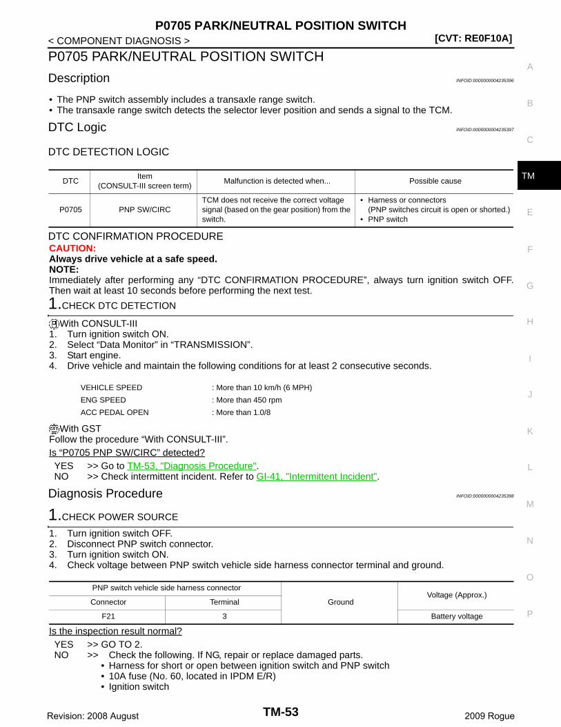
P0705 PARK/NEUTRAL POSITION SWITCH[CVT: RE0F10A]
C
E
F
G
H
I
J
K
L
M
A
B
M
N
O
P
< COMPONENT DIAGNOSIS >
T
P0705 PARK/NEUTRAL POSITION SWITCH
Description INFOID:0000000004235396
• The PNP switch assembly includes a transaxle range switch.• The transaxle range switch detects the selector lever position and sends a signal to the TCM.
DTC Logic INFOID:0000000004235397
DTC DETECTION LOGIC
DTC CONFIRMATION PROCEDURECAUTION:Always drive vehicle at a safe speed.NOTE:Immediately after performing any “DTC CONFIRMATION PROCEDURE”, always turn ignition switch OFF.Then wait at least 10 seconds before performing the next test.
1.CHECK DTC DETECTION
With CONSULT-III1. Turn ignition switch ON.2. Select “Data Monitor” in “TRANSMISSION”.3. Start engine.4. Drive vehicle and maintain the following conditions for at least 2 consecutive seconds.
With GSTFollow the procedure “With CONSULT-III”.Is “P0705 PNP SW/CIRC” detected?YES >> Go to TM-53, "Diagnosis Procedure".NO >> Check intermittent incident. Refer to GI-41, "Intermittent Incident".
Diagnosis Procedure INFOID:0000000004235398
1.CHECK POWER SOURCE
1. Turn ignition switch OFF.2. Disconnect PNP switch connector.3. Turn ignition switch ON.4. Check voltage between PNP switch vehicle side harness connector terminal and ground.
Is the inspection result normal?YES >> GO TO 2.NO >> Check the following. If NG, repair or replace damaged parts.
• Harness for short or open between ignition switch and PNP switch• 10A fuse (No. 60, located in IPDM E/R)• Ignition switch
DTCItem
(CONSULT-III screen term)Malfunction is detected when... Possible cause
P0705 PNP SW/CIRCTCM does not receive the correct voltage signal (based on the gear position) from the switch.
• Harness or connectors(PNP switches circuit is open or shorted.)
• PNP switch
VEHICLE SPEED : More than 10 km/h (6 MPH)
ENG SPEED : More than 450 rpm
ACC PEDAL OPEN : More than 1.0/8
PNP switch vehicle side harness connector
GroundVoltage (Approx.)
Connector Terminal
F21 3 Battery voltage
TM-53Revision: 2008 August 2009 Rogue
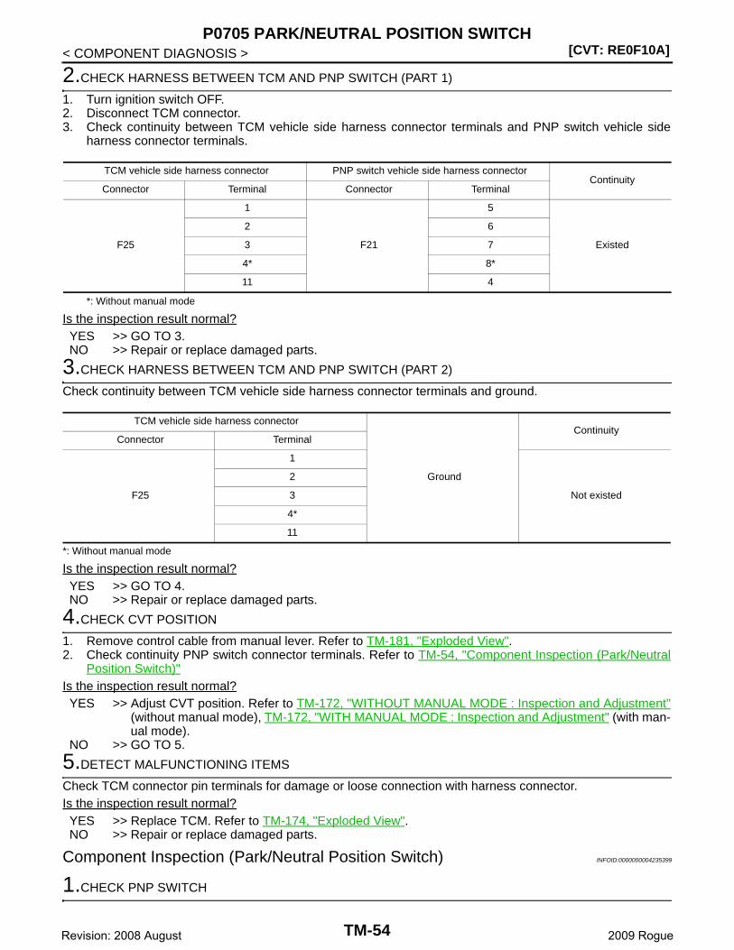
[CVT: RE0F10A]P0705 PARK/NEUTRAL POSITION SWITCH
< COMPONENT DIAGNOSIS >
2.CHECK HARNESS BETWEEN TCM AND PNP SWITCH (PART 1)
1. Turn ignition switch OFF.2. Disconnect TCM connector.3. Check continuity between TCM vehicle side harness connector terminals and PNP switch vehicle side
harness connector terminals.
*: Without manual mode
Is the inspection result normal?YES >> GO TO 3.NO >> Repair or replace damaged parts.
3.CHECK HARNESS BETWEEN TCM AND PNP SWITCH (PART 2)
Check continuity between TCM vehicle side harness connector terminals and ground.
*: Without manual mode
Is the inspection result normal?YES >> GO TO 4.NO >> Repair or replace damaged parts.
4.CHECK CVT POSITION
1. Remove control cable from manual lever. Refer to TM-181, "Exploded View".2. Check continuity PNP switch connector terminals. Refer to TM-54, "Component Inspection (Park/Neutral
Position Switch)"Is the inspection result normal?YES >> Adjust CVT position. Refer to TM-172, "WITHOUT MANUAL MODE : Inspection and Adjustment"
(without manual mode), TM-172, "WITH MANUAL MODE : Inspection and Adjustment" (with man-ual mode).
NO >> GO TO 5.
5.DETECT MALFUNCTIONING ITEMS
Check TCM connector pin terminals for damage or loose connection with harness connector.Is the inspection result normal?YES >> Replace TCM. Refer to TM-174, "Exploded View".NO >> Repair or replace damaged parts.
Component Inspection (Park/Neutral Position Switch) INFOID:0000000004235399
1.CHECK PNP SWITCH
TCM vehicle side harness connector PNP switch vehicle side harness connectorContinuity
Connector Terminal Connector Terminal
F25
1
F21
5
Existed
2 6
3 7
4* 8*
11 4
TCM vehicle side harness connector
Ground
ContinuityConnector Terminal
F25
1
Not existed
2
3
4*
11
TM-54Revision: 2008 August 2009 Rogue
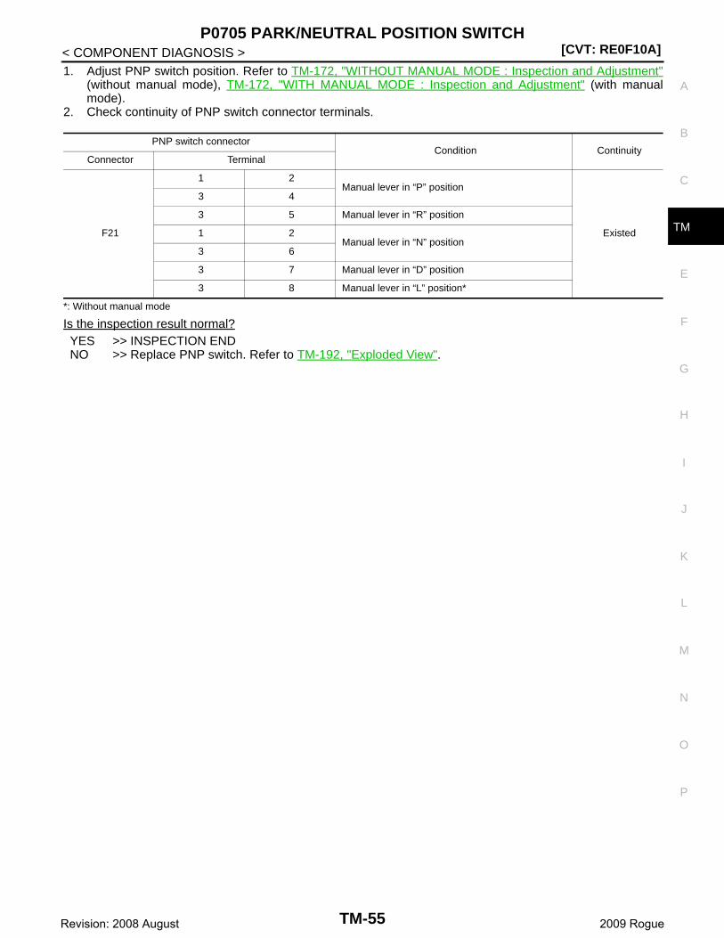
P0705 PARK/NEUTRAL POSITION SWITCH[CVT: RE0F10A]
C
E
F
G
H
I
J
K
L
M
A
B
M
N
O
P
< COMPONENT DIAGNOSIS >
T
1. Adjust PNP switch position. Refer to TM-172, "WITHOUT MANUAL MODE : Inspection and Adjustment"(without manual mode), TM-172, "WITH MANUAL MODE : Inspection and Adjustment" (with manualmode).
2. Check continuity of PNP switch connector terminals.
*: Without manual mode
Is the inspection result normal?YES >> INSPECTION ENDNO >> Replace PNP switch. Refer to TM-192, "Exploded View".
PNP switch connectorCondition Continuity
Connector Terminal
F21
1 2Manual lever in “P” position
Existed
3 4
3 5 Manual lever in “R” position
1 2Manual lever in “N” position
3 6
3 7 Manual lever in “D” position
3 8 Manual lever in “L” position*
TM-55Revision: 2008 August 2009 Rogue
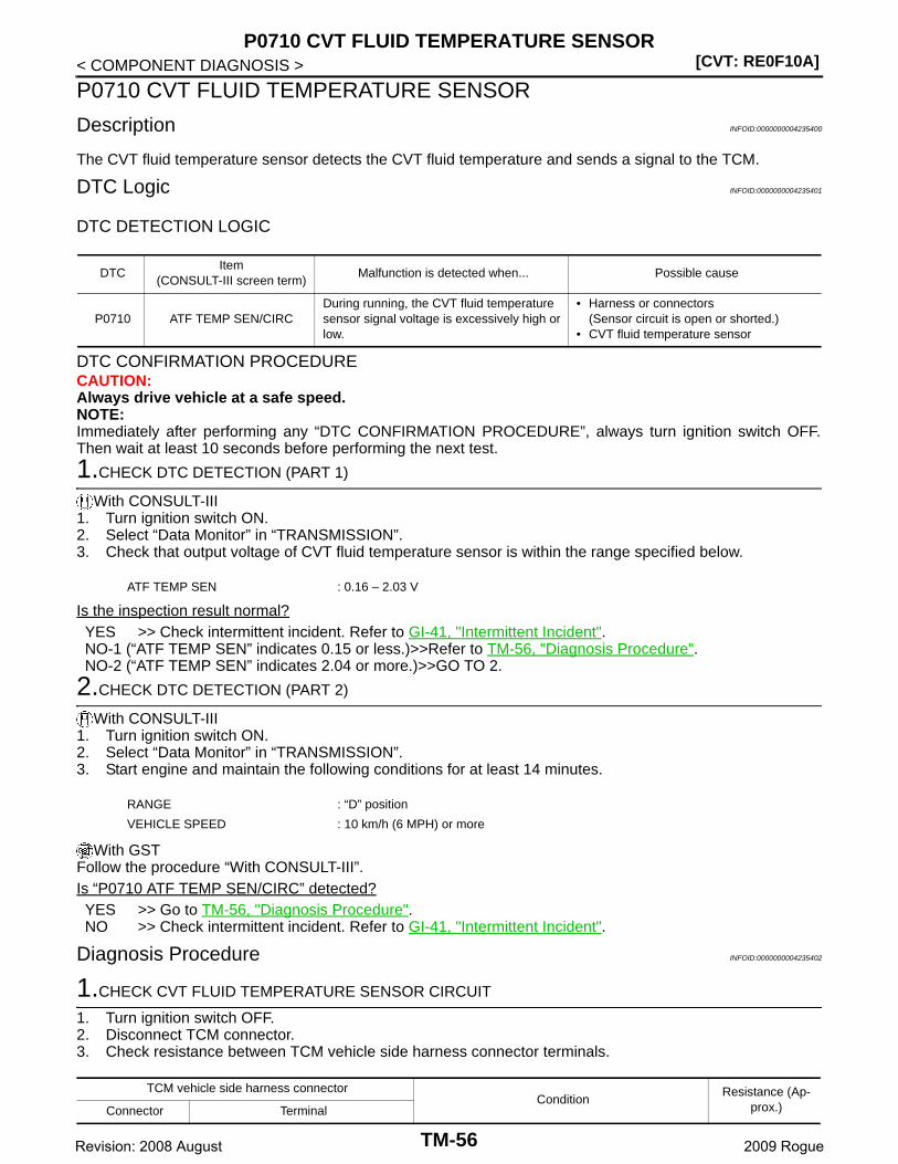
[CVT: RE0F10A]P0710 CVT FLUID TEMPERATURE SENSOR
< COMPONENT DIAGNOSIS >
P0710 CVT FLUID TEMPERATURE SENSOR
Description INFOID:0000000004235400
The CVT fluid temperature sensor detects the CVT fluid temperature and sends a signal to the TCM.
DTC Logic INFOID:0000000004235401
DTC DETECTION LOGIC
DTC CONFIRMATION PROCEDURECAUTION:Always drive vehicle at a safe speed.NOTE:Immediately after performing any “DTC CONFIRMATION PROCEDURE”, always turn ignition switch OFF.Then wait at least 10 seconds before performing the next test.
1.CHECK DTC DETECTION (PART 1)
With CONSULT-III1. Turn ignition switch ON.2. Select “Data Monitor” in “TRANSMISSION”.3. Check that output voltage of CVT fluid temperature sensor is within the range specified below.
Is the inspection result normal?YES >> Check intermittent incident. Refer to GI-41, "Intermittent Incident".NO-1 (“ATF TEMP SEN” indicates 0.15 or less.)>>Refer to TM-56, "Diagnosis Procedure".NO-2 (“ATF TEMP SEN” indicates 2.04 or more.)>>GO TO 2.
2.CHECK DTC DETECTION (PART 2)
With CONSULT-III1. Turn ignition switch ON.2. Select “Data Monitor” in “TRANSMISSION”.3. Start engine and maintain the following conditions for at least 14 minutes.
With GSTFollow the procedure “With CONSULT-III”.Is “P0710 ATF TEMP SEN/CIRC” detected?YES >> Go to TM-56, "Diagnosis Procedure".NO >> Check intermittent incident. Refer to GI-41, "Intermittent Incident".
Diagnosis Procedure INFOID:0000000004235402
1.CHECK CVT FLUID TEMPERATURE SENSOR CIRCUIT
1. Turn ignition switch OFF.2. Disconnect TCM connector.3. Check resistance between TCM vehicle side harness connector terminals.
DTCItem
(CONSULT-III screen term)Malfunction is detected when... Possible cause
P0710 ATF TEMP SEN/CIRCDuring running, the CVT fluid temperature sensor signal voltage is excessively high or low.
• Harness or connectors(Sensor circuit is open or shorted.)
• CVT fluid temperature sensor
ATF TEMP SEN : 0.16 – 2.03 V
RANGE : “D” position
VEHICLE SPEED : 10 km/h (6 MPH) or more
TCM vehicle side harness connectorCondition
Resistance (Ap-prox.)Connector Terminal
TM-56Revision: 2008 August 2009 Rogue
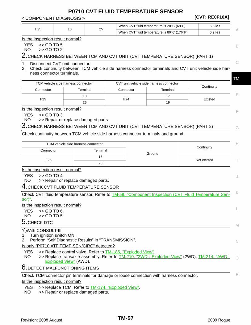
P0710 CVT FLUID TEMPERATURE SENSOR[CVT: RE0F10A]
C
E
F
G
H
I
J
K
L
M
A
B
M
N
O
P
< COMPONENT DIAGNOSIS >
T
Is the inspection result normal?YES >> GO TO 5.NO >> GO TO 2.
2.CHECK HARNESS BETWEEN TCM AND CVT UNIT (CVT TEMPERATURE SENSOR) (PART 1)
1. Disconnect CVT unit connector.2. Check continuity between TCM vehicle side harness connector terminals and CVT unit vehicle side har-
ness connector terminals.
Is the inspection result normal?YES >> GO TO 3.NO >> Repair or replace damaged parts.
3.CHECK HARNESS BETWEEN TCM AND CVT UNIT (CVT TEMPERATURE SENSOR) (PART 2)
Check continuity between TCM vehicle side harness connector terminals and ground.
Is the inspection result normal?YES >> GO TO 4.NO >> Repair or replace damaged parts.
4.CHECK CVT FLUID TEMPERATURE SENSOR
Check CVT fluid temperature sensor. Refer to TM-58, "Component Inspection (CVT Fluid Temperature Sen-sor)".Is the inspection result normal?YES >> GO TO 6.NO >> GO TO 5.
5.CHECK DTC
With CONSULT-III1. Turn ignition switch ON.2. Perform “Self Diagnostic Results” in “TRANSMISSION”.Is only “P0710 ATF TEMP SEN/CIRC” detected?YES >> Replace control valve. Refer to TM-185, "Exploded View".NO >> Replace transaxle assembly. Refer to TM-210, "2WD : Exploded View" (2WD), TM-214, "AWD :
Exploded View" (AWD).
6.DETECT MALFUNCTIONING ITEMS
Check TCM connector pin terminals for damage or loose connection with harness connector.Is the inspection result normal?YES >> Replace TCM. Refer to TM-174, "Exploded View".NO >> Repair or replace damaged parts.
F25 13 25When CVT fluid temperature is 20°C (68°F) 6.5 kΩ
When CVT fluid temperature is 80°C (176°F) 0.9 kΩ
TCM vehicle side harness connector CVT unit vehicle side harness connectorContinuity
Connector Terminal Connector Terminal
F2513
F2417
Existed25 19
TCM vehicle side harness connector
Ground
ContinuityConnector Terminal
F2513
Not existed25
TM-57Revision: 2008 August 2009 Rogue
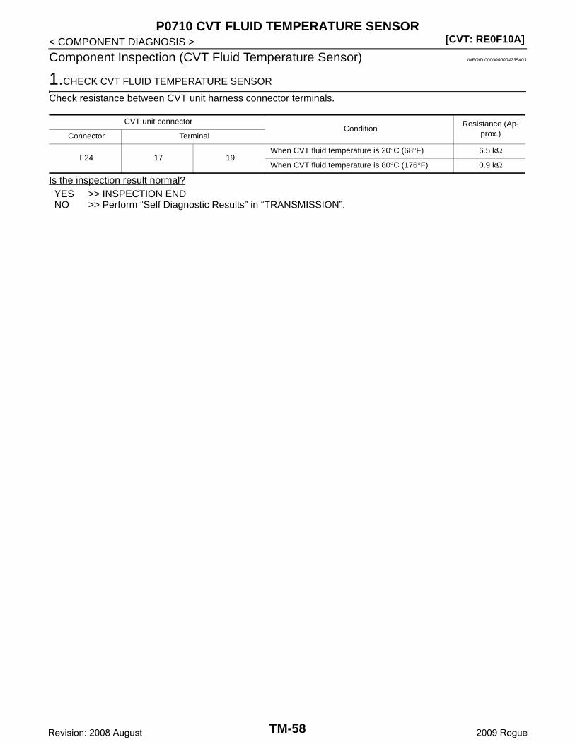
[CVT: RE0F10A]P0710 CVT FLUID TEMPERATURE SENSOR
< COMPONENT DIAGNOSIS >
Component Inspection (CVT Fluid Temperature Sensor) INFOID:0000000004235403
1.CHECK CVT FLUID TEMPERATURE SENSOR
Check resistance between CVT unit harness connector terminals.
Is the inspection result normal?YES >> INSPECTION ENDNO >> Perform “Self Diagnostic Results” in “TRANSMISSION”.
CVT unit connectorCondition
Resistance (Ap-prox.)Connector Terminal
F24 17 19When CVT fluid temperature is 20°C (68°F) 6.5 kΩ
When CVT fluid temperature is 80°C (176°F) 0.9 kΩ
TM-58Revision: 2008 August 2009 Rogue

P0715 INPUT SPEED SENSOR (PRI SPEED SENSOR)[CVT: RE0F10A]
C
E
F
G
H
I
J
K
L
M
A
B
M
N
O
P
< COMPONENT DIAGNOSIS >
T
P0715 INPUT SPEED SENSOR (PRI SPEED SENSOR)
Description INFOID:0000000004235404
The input speed sensor (primary speed sensor) detects the primary pulley revolution speed and sends a sig-nal to the TCM.
DTC Logic INFOID:0000000004235405
DTC DETECTION LOGIC
DTC CONFIRMATION PROCEDURECAUTION:Always drive vehicle at a safe speed.NOTE:IImmediately after performing any “DTC CONFIRMATION PROCEDURE”, always turn ignition switch OFF.Then wait at least 10 seconds before performing the next test.
1.CHECK DTC DETECTION
With CONSULT-III1. Turn ignition switch ON.2. Select “Data Monitor” in “TRANSMISSION”.3. Start engine and maintain the following conditions for at least 5 consecutive seconds.
With GSTFollow the procedure “With CONSULT-III”.Is “P0715 INPUT SPD SEN/CIRC” detected?YES >> Go to TM-59, "Diagnosis Procedure".NO >> Check intermittent incident. Refer to GI-41, "Intermittent Incident".
Diagnosis Procedure INFOID:0000000004235406
1.CHECK INPUT SPEED SENSOR (PRIMARY SPEED SENSOR)
With CONSULT-III1. Start engine.2. Check voltage between TCM connector terminals.
3. If OK, check pulse when vehicle cruises.
DTCItem
(CONSULT-III screen term)Malfunction is detected when... Possible cause
P0715 INPUT SPD SEN/CIRC
• Input speed sensor (primary speed sen-sor) signal is not input due to an open cir-cuit.
• An unexpected signal is input when vehi-cle is being driven.
• Harness or connectors(Sensor circuit is open or shorted.)
• Input speed sensor (primary speed sen-sor)
VEHICLE SPEED : 10 km/h (6 MPH) or more
ACC PEDAL OPEN : More than 1.0/8
RANGE : “D” position
ENG SPEED : 450 rpm or more
Driving location : Driving the vehicle uphill (increased engine load) will help maintain the driving conditions required for this test.
TCM connectorVoltage (Approx.)
Connector Terminal
F25 2546
Battery voltage48
TM-59Revision: 2008 August 2009 Rogue
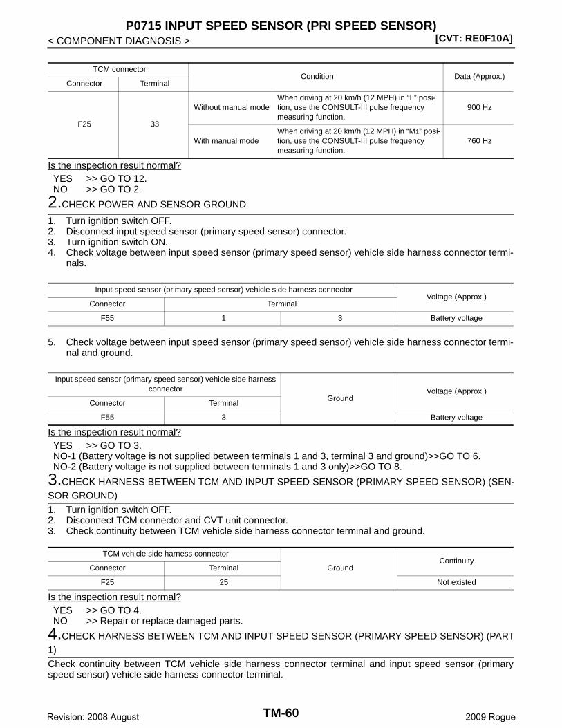
[CVT: RE0F10A]P0715 INPUT SPEED SENSOR (PRI SPEED SENSOR)
< COMPONENT DIAGNOSIS >
Is the inspection result normal?YES >> GO TO 12.NO >> GO TO 2.
2.CHECK POWER AND SENSOR GROUND
1. Turn ignition switch OFF.2. Disconnect input speed sensor (primary speed sensor) connector.3. Turn ignition switch ON.4. Check voltage between input speed sensor (primary speed sensor) vehicle side harness connector termi-
nals.
5. Check voltage between input speed sensor (primary speed sensor) vehicle side harness connector termi-nal and ground.
Is the inspection result normal?YES >> GO TO 3.NO-1 (Battery voltage is not supplied between terminals 1 and 3, terminal 3 and ground)>>GO TO 6.NO-2 (Battery voltage is not supplied between terminals 1 and 3 only)>>GO TO 8.
3.CHECK HARNESS BETWEEN TCM AND INPUT SPEED SENSOR (PRIMARY SPEED SENSOR) (SEN-SOR GROUND)
1. Turn ignition switch OFF.2. Disconnect TCM connector and CVT unit connector.3. Check continuity between TCM vehicle side harness connector terminal and ground.
Is the inspection result normal?YES >> GO TO 4.NO >> Repair or replace damaged parts.
4.CHECK HARNESS BETWEEN TCM AND INPUT SPEED SENSOR (PRIMARY SPEED SENSOR) (PART1)
Check continuity between TCM vehicle side harness connector terminal and input speed sensor (primaryspeed sensor) vehicle side harness connector terminal.
TCM connectorCondition Data (Approx.)
Connector Terminal
F25 33
Without manual modeWhen driving at 20 km/h (12 MPH) in “L” posi-tion, use the CONSULT-III pulse frequency measuring function.
900 Hz
With manual modeWhen driving at 20 km/h (12 MPH) in “M1” posi-tion, use the CONSULT-III pulse frequency measuring function.
760 Hz
Input speed sensor (primary speed sensor) vehicle side harness connectorVoltage (Approx.)
Connector Terminal
F55 1 3 Battery voltage
Input speed sensor (primary speed sensor) vehicle side harness connector
GroundVoltage (Approx.)
Connector Terminal
F55 3 Battery voltage
TCM vehicle side harness connector
GroundContinuity
Connector Terminal
F25 25 Not existed
TM-60Revision: 2008 August 2009 Rogue
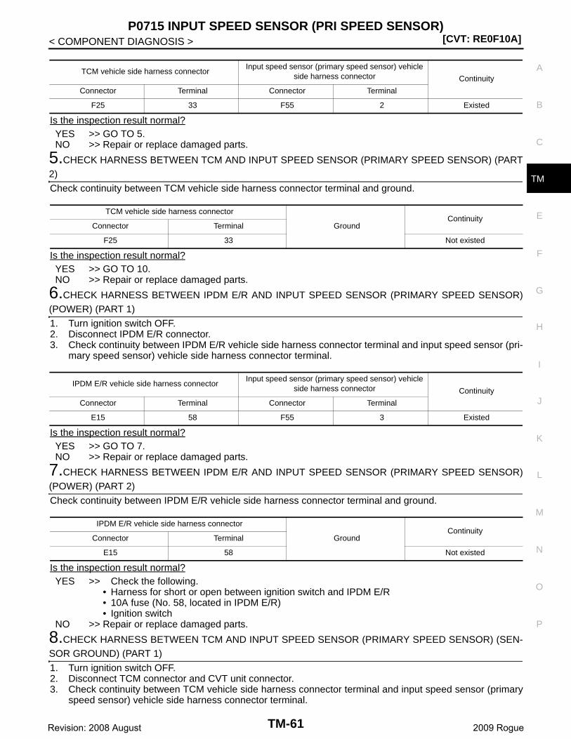
P0715 INPUT SPEED SENSOR (PRI SPEED SENSOR)[CVT: RE0F10A]
C
E
F
G
H
I
J
K
L
M
A
B
M
N
O
P
< COMPONENT DIAGNOSIS >
T
Is the inspection result normal?YES >> GO TO 5.NO >> Repair or replace damaged parts.
5.CHECK HARNESS BETWEEN TCM AND INPUT SPEED SENSOR (PRIMARY SPEED SENSOR) (PART2)
Check continuity between TCM vehicle side harness connector terminal and ground.
Is the inspection result normal?YES >> GO TO 10.NO >> Repair or replace damaged parts.
6.CHECK HARNESS BETWEEN IPDM E/R AND INPUT SPEED SENSOR (PRIMARY SPEED SENSOR)(POWER) (PART 1)
1. Turn ignition switch OFF.2. Disconnect IPDM E/R connector.3. Check continuity between IPDM E/R vehicle side harness connector terminal and input speed sensor (pri-
mary speed sensor) vehicle side harness connector terminal.
Is the inspection result normal?YES >> GO TO 7.NO >> Repair or replace damaged parts.
7.CHECK HARNESS BETWEEN IPDM E/R AND INPUT SPEED SENSOR (PRIMARY SPEED SENSOR)(POWER) (PART 2)
Check continuity between IPDM E/R vehicle side harness connector terminal and ground.
Is the inspection result normal?YES >> Check the following.
• Harness for short or open between ignition switch and IPDM E/R• 10A fuse (No. 58, located in IPDM E/R)• Ignition switch
NO >> Repair or replace damaged parts.
8.CHECK HARNESS BETWEEN TCM AND INPUT SPEED SENSOR (PRIMARY SPEED SENSOR) (SEN-SOR GROUND) (PART 1)
1. Turn ignition switch OFF.2. Disconnect TCM connector and CVT unit connector.3. Check continuity between TCM vehicle side harness connector terminal and input speed sensor (primary
speed sensor) vehicle side harness connector terminal.
TCM vehicle side harness connectorInput speed sensor (primary speed sensor) vehicle
side harness connector Continuity
Connector Terminal Connector Terminal
F25 33 F55 2 Existed
TCM vehicle side harness connector
GroundContinuity
Connector Terminal
F25 33 Not existed
IPDM E/R vehicle side harness connectorInput speed sensor (primary speed sensor) vehicle
side harness connector Continuity
Connector Terminal Connector Terminal
E15 58 F55 3 Existed
IPDM E/R vehicle side harness connector
GroundContinuity
Connector Terminal
E15 58 Not existed
TM-61Revision: 2008 August 2009 Rogue
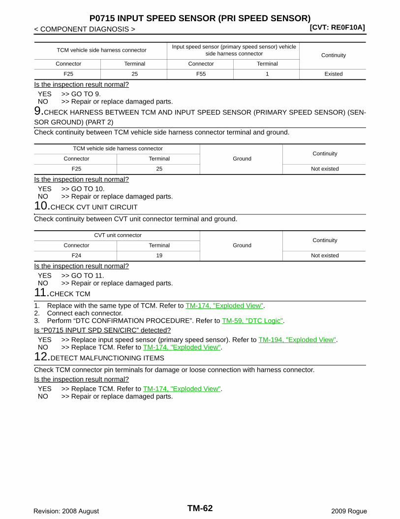
[CVT: RE0F10A]P0715 INPUT SPEED SENSOR (PRI SPEED SENSOR)
< COMPONENT DIAGNOSIS >
Is the inspection result normal?YES >> GO TO 9.NO >> Repair or replace damaged parts.
9.CHECK HARNESS BETWEEN TCM AND INPUT SPEED SENSOR (PRIMARY SPEED SENSOR) (SEN-SOR GROUND) (PART 2)
Check continuity between TCM vehicle side harness connector terminal and ground.
Is the inspection result normal?YES >> GO TO 10.NO >> Repair or replace damaged parts.
10.CHECK CVT UNIT CIRCUIT
Check continuity between CVT unit connector terminal and ground.
Is the inspection result normal?YES >> GO TO 11.NO >> Repair or replace damaged parts.
11.CHECK TCM
1. Replace with the same type of TCM. Refer to TM-174, "Exploded View".2. Connect each connector.3. Perform “DTC CONFIRMATION PROCEDURE”. Refer to TM-59, "DTC Logic".Is “P0715 INPUT SPD SEN/CIRC” detected?YES >> Replace input speed sensor (primary speed sensor). Refer to TM-194, "Exploded View".NO >> Replace TCM. Refer to TM-174, "Exploded View".
12.DETECT MALFUNCTIONING ITEMS
Check TCM connector pin terminals for damage or loose connection with harness connector.Is the inspection result normal?YES >> Replace TCM. Refer to TM-174, "Exploded View".NO >> Repair or replace damaged parts.
TCM vehicle side harness connectorInput speed sensor (primary speed sensor) vehicle
side harness connector Continuity
Connector Terminal Connector Terminal
F25 25 F55 1 Existed
TCM vehicle side harness connector
GroundContinuity
Connector Terminal
F25 25 Not existed
CVT unit connector
GroundContinuity
Connector Terminal
F24 19 Not existed
TM-62Revision: 2008 August 2009 Rogue

P0720 VEHICLE SPEED SENSOR CVT (SECONDARY SPEED SENSOR)[CVT: RE0F10A]
C
E
F
G
H
I
J
K
L
M
A
B
M
N
O
P
< COMPONENT DIAGNOSIS >
T
P0720 VEHICLE SPEED SENSOR CVT (SECONDARY SPEED SENSOR)
Description INFOID:0000000004235407
The vehicle speed sensor CVT [output speed sensor (secondary speed sensor)] detects the revolution of theCVT output shaft and emits a pulse signal. The pulse signal is transmitted to the TCM, which converts it intovehicle speed.
DTC Logic INFOID:0000000004235408
DTC DETECTION LOGIC
DTC CONFIRMATION PROCEDURECAUTION:Always drive vehicle at a safe speed.NOTE:Immediately after performing any “DTC CONFIRMATION PROCEDURE”, always turn ignition switch OFF.Then wait at least 10 seconds before performing the next test.
1.CHECK DTC DETECTION
With CONSULT-III1. Turn ignition switch ON.2. Select “Data Monitor” in “TRANSMISSION”.3. Start engine and maintain the following conditions for at least 12 consecutive seconds.
With GSTFollow the procedure “With CONSULT-III”.Is “P0720 VEH SPD SEN/CIR AT” detected?YES >> Go to TM-63, "Diagnosis Procedure".NO >> Check intermittent incident. Refer to GI-41, "Intermittent Incident".
Diagnosis Procedure INFOID:0000000004235409
1.CHECK OUTPUT SPEED SENSOR (SECONDARY SPEED SENSOR)
With CONSULT-III1. Start engine.2. Check voltage between TCM connector terminals.
3. If OK, check pulse when vehicle drive.
DTCItem
(CONSULT-III screen term)Malfunction is detected when... Possible cause
P0720 VEH SPD SEN/CIR AT
• Signal from vehicle speed sensor CVT [output speed sensor (secondary speed sensor)] is not input due to open or short circuit.
• Unexpected signal is input during running.
• Harness or connectors(Sensor circuit is open or shorted.)
• Output speed sensor (secondary speed sensor)
ACC PEDAL OPEN : More than 1.0/8
RANGE : “D” position
Driving location : Driving the vehicle uphill (increased engine load) will help maintain the driving conditions required for this test.
TCM connectorVoltage (Approx.)
Connector Terminal
F25 746
Battery voltage48
TM-63Revision: 2008 August 2009 Rogue
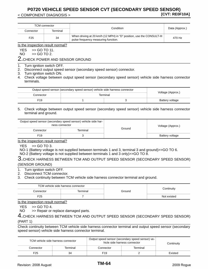
[CVT: RE0F10A]P0720 VEHICLE SPEED SENSOR CVT (SECONDARY SPEED SENSOR)
< COMPONENT DIAGNOSIS >
Is the inspection result normal?YES >> GO TO 11.NO >> GO TO 2.
2.CHECK POWER AND SENSOR GROUND
1. Turn ignition switch OFF.2. Disconnect output speed sensor (secondary speed sensor) connector.3. Turn ignition switch ON.4. Check voltage between output speed sensor (secondary speed sensor) vehicle side harness connector
terminals.
5. Check voltage between output speed sensor (secondary speed sensor) vehicle side harness connectorterminal and ground.
Is the inspection result normal?YES >> GO TO 3.NO-1 (Battery voltage is not supplied between terminals 1 and 3, terminal 3 and ground)>>GO TO 6.NO-2 (Battery voltage is not supplied between terminals 1 and 3 only)>>GO TO 8.
3.CHECK HARNESS BETWEEN TCM AND OUTPUT SPEED SENSOR (SECONDARY SPEED SENSOR)(SENSOR GROUND)
1. Turn ignition switch OFF.2. Disconnect TCM connector.3. Check continuity between TCM vehicle side harness connector terminal and ground.
Is the inspection result normal?YES >> GO TO 4.NO >> Repair or replace damaged parts.
4.CHECK HARNESS BETWEEN TCM AND OUTPUT SPEED SENSOR (SECONDARY SPEED SENSOR)(PART 1)
Check continuity between TCM vehicle side harness connector terminal and output speed sensor (secondaryspeed sensor) vehicle side harness connector terminal.
TCM connectorCondition Data (Approx.)
Connector Terminal
F25 34When driving at 20 km/h (12 MPH) in “D” position, use the CONSULT-III pulse frequency measuring function.
470 Hz
Output speed sensor (secondary speed sensor) vehicle side harness connectorVoltage (Approx.)
Connector Terminal
F19 1 3 Battery voltage
Output speed sensor (secondary speed sensor) vehicle side har-ness connector
GroundVoltage (Approx.)
Connector Terminal
F19 3 Battery voltage
TCM vehicle side harness connector
GroundContinuity
Connector Terminal
F25 7 Not existed
TCM vehicle side harness connectorOutput speed sensor (secondary speed sensor) ve-
hicle side harness connector Continuity
Connector Terminal Connector Terminal
F25 34 F19 2 Existed
TM-64Revision: 2008 August 2009 Rogue
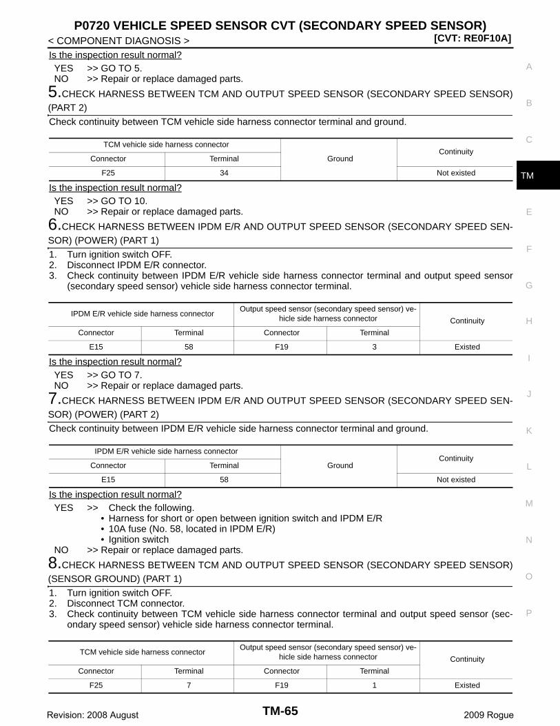
P0720 VEHICLE SPEED SENSOR CVT (SECONDARY SPEED SENSOR)[CVT: RE0F10A]
C
E
F
G
H
I
J
K
L
M
A
B
M
N
O
P
< COMPONENT DIAGNOSIS >
T
Is the inspection result normal?YES >> GO TO 5.NO >> Repair or replace damaged parts.
5.CHECK HARNESS BETWEEN TCM AND OUTPUT SPEED SENSOR (SECONDARY SPEED SENSOR)(PART 2)
Check continuity between TCM vehicle side harness connector terminal and ground.
Is the inspection result normal?YES >> GO TO 10.NO >> Repair or replace damaged parts.
6.CHECK HARNESS BETWEEN IPDM E/R AND OUTPUT SPEED SENSOR (SECONDARY SPEED SEN-SOR) (POWER) (PART 1)
1. Turn ignition switch OFF.2. Disconnect IPDM E/R connector.3. Check continuity between IPDM E/R vehicle side harness connector terminal and output speed sensor
(secondary speed sensor) vehicle side harness connector terminal.
Is the inspection result normal?YES >> GO TO 7.NO >> Repair or replace damaged parts.
7.CHECK HARNESS BETWEEN IPDM E/R AND OUTPUT SPEED SENSOR (SECONDARY SPEED SEN-SOR) (POWER) (PART 2)
Check continuity between IPDM E/R vehicle side harness connector terminal and ground.
Is the inspection result normal?YES >> Check the following.
• Harness for short or open between ignition switch and IPDM E/R• 10A fuse (No. 58, located in IPDM E/R)• Ignition switch
NO >> Repair or replace damaged parts.
8.CHECK HARNESS BETWEEN TCM AND OUTPUT SPEED SENSOR (SECONDARY SPEED SENSOR)(SENSOR GROUND) (PART 1)
1. Turn ignition switch OFF.2. Disconnect TCM connector.3. Check continuity between TCM vehicle side harness connector terminal and output speed sensor (sec-
ondary speed sensor) vehicle side harness connector terminal.
TCM vehicle side harness connector
GroundContinuity
Connector Terminal
F25 34 Not existed
IPDM E/R vehicle side harness connectorOutput speed sensor (secondary speed sensor) ve-
hicle side harness connector Continuity
Connector Terminal Connector Terminal
E15 58 F19 3 Existed
IPDM E/R vehicle side harness connector
GroundContinuity
Connector Terminal
E15 58 Not existed
TCM vehicle side harness connectorOutput speed sensor (secondary speed sensor) ve-
hicle side harness connector Continuity
Connector Terminal Connector Terminal
F25 7 F19 1 Existed
TM-65Revision: 2008 August 2009 Rogue
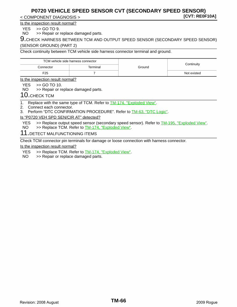
[CVT: RE0F10A]P0720 VEHICLE SPEED SENSOR CVT (SECONDARY SPEED SENSOR)
< COMPONENT DIAGNOSIS >Is the inspection result normal?YES >> GO TO 9.NO >> Repair or replace damaged parts.
9.CHECK HARNESS BETWEEN TCM AND OUTPUT SPEED SENSOR (SECONDARY SPEED SENSOR)(SENSOR GROUND) (PART 2)
Check continuity between TCM vehicle side harness connector terminal and ground.
Is the inspection result normal?YES >> GO TO 10.NO >> Repair or replace damaged parts.
10.CHECK TCM
1. Replace with the same type of TCM. Refer to TM-174, "Exploded View".2. Connect each connector.3. Perform “DTC CONFIRMATION PROCEDURE”. Refer to TM-63, "DTC Logic".Is “P0720 VEH SPD SEN/CIR AT” detected?YES >> Replace output speed sensor (secondary speed sensor). Refer to TM-195, "Exploded View".NO >> Replace TCM. Refer to TM-174, "Exploded View".
11.DETECT MALFUNCTIONING ITEMS
Check TCM connector pin terminals for damage or loose connection with harness connector.Is the inspection result normal?YES >> Replace TCM. Refer to TM-174, "Exploded View".NO >> Repair or replace damaged parts.
TCM vehicle side harness connector
GroundContinuity
Connector Terminal
F25 7 Not existed
TM-66Revision: 2008 August 2009 Rogue
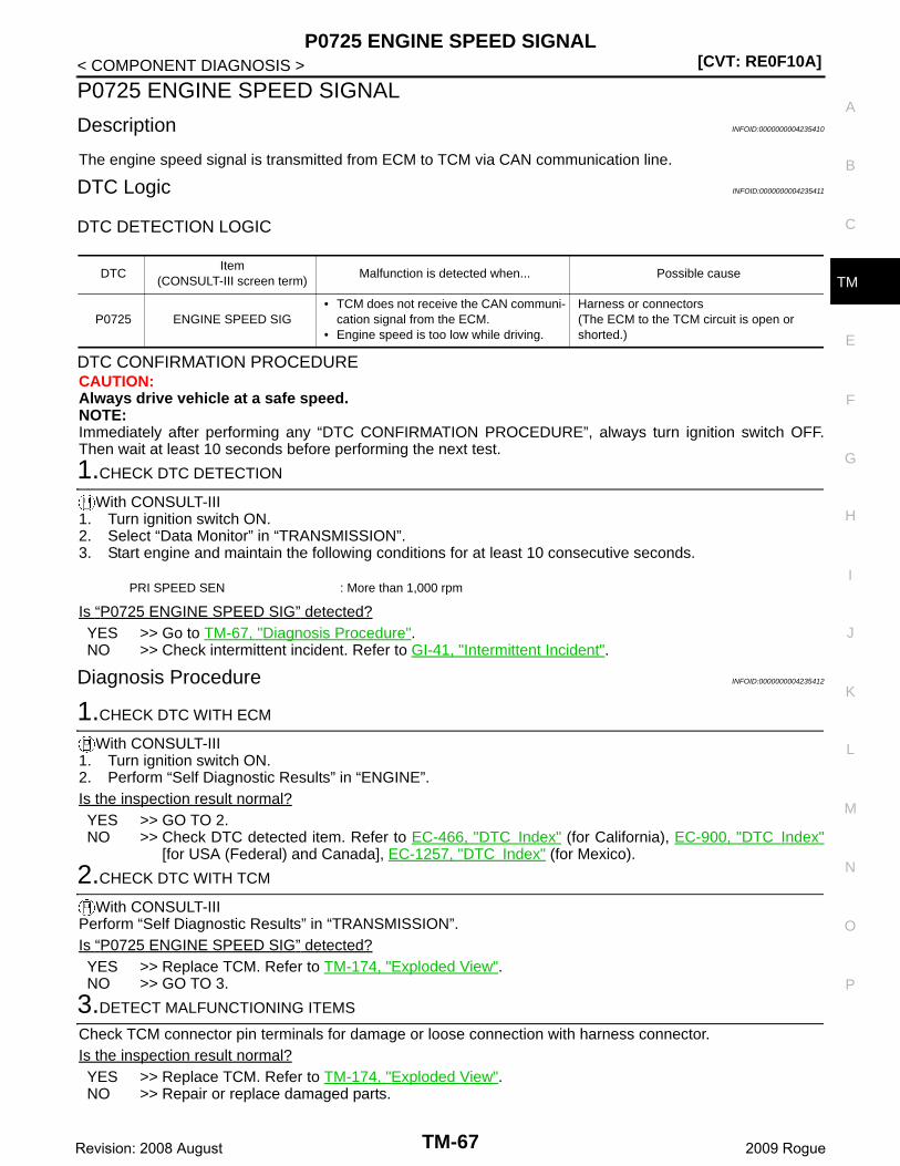
P0725 ENGINE SPEED SIGNAL[CVT: RE0F10A]
C
E
F
G
H
I
J
K
L
M
A
B
M
N
O
P
< COMPONENT DIAGNOSIS >
T
P0725 ENGINE SPEED SIGNAL
Description INFOID:0000000004235410
The engine speed signal is transmitted from ECM to TCM via CAN communication line.
DTC Logic INFOID:0000000004235411
DTC DETECTION LOGIC
DTC CONFIRMATION PROCEDURECAUTION:Always drive vehicle at a safe speed.NOTE:Immediately after performing any “DTC CONFIRMATION PROCEDURE”, always turn ignition switch OFF.Then wait at least 10 seconds before performing the next test.
1.CHECK DTC DETECTION
With CONSULT-III1. Turn ignition switch ON.2. Select “Data Monitor” in “TRANSMISSION”.3. Start engine and maintain the following conditions for at least 10 consecutive seconds.
Is “P0725 ENGINE SPEED SIG” detected?YES >> Go to TM-67, "Diagnosis Procedure".NO >> Check intermittent incident. Refer to GI-41, "Intermittent Incident".
Diagnosis Procedure INFOID:0000000004235412
1.CHECK DTC WITH ECM
With CONSULT-III1. Turn ignition switch ON.2. Perform “Self Diagnostic Results” in “ENGINE”.Is the inspection result normal?YES >> GO TO 2.NO >> Check DTC detected item. Refer to EC-466, "DTC Index" (for California), EC-900, "DTC Index"
[for USA (Federal) and Canada], EC-1257, "DTC Index" (for Mexico).
2.CHECK DTC WITH TCM
With CONSULT-IIIPerform “Self Diagnostic Results” in “TRANSMISSION”.Is “P0725 ENGINE SPEED SIG” detected?YES >> Replace TCM. Refer to TM-174, "Exploded View".NO >> GO TO 3.
3.DETECT MALFUNCTIONING ITEMS
Check TCM connector pin terminals for damage or loose connection with harness connector.Is the inspection result normal?YES >> Replace TCM. Refer to TM-174, "Exploded View".NO >> Repair or replace damaged parts.
DTCItem
(CONSULT-III screen term)Malfunction is detected when... Possible cause
P0725 ENGINE SPEED SIG• TCM does not receive the CAN communi-
cation signal from the ECM.• Engine speed is too low while driving.
Harness or connectors(The ECM to the TCM circuit is open or shorted.)
PRI SPEED SEN : More than 1,000 rpm
TM-67Revision: 2008 August 2009 Rogue

[CVT: RE0F10A]P0730 BELT DAMAGE
< COMPONENT DIAGNOSIS >
P0730 BELT DAMAGE
Description INFOID:0000000004235413
TCM selects the gear ratio using the engine load (throttle position), the primary pulley revolution speed, andthe secondary pulley revolution speed as input signals. Then it changes the operating pressure of the primarypulley and the secondary pulley and changes the groove width of the pulley.
DTC Logic INFOID:0000000004235414
DTC DETECTION LOGIC
DTC CONFIRMATION PROCEDURECAUTION:Always drive vehicle at a safe speed.NOTE:Immediately after performing any “DTC CONFIRMATION PROCEDURE”, always turn ignition switch OFF.Then wait at least 10 seconds before performing the next test.
1.CHECK DTC DETECTION
With CONSULT-III1. Turn ignition switch ON.2. Select “Data Monitor” in “TRANSMISSION”.3. Make sure that output voltage of CVT fluid temperature sensor is within the range specified below.
4. Start engine and maintain the following conditions for at least 30 consecutive seconds.
Is “P0730 BELT DAMG” detected?YES >> Go to TM-68, "Diagnosis Procedure".NO >> Check intermittent incident. Refer to GI-41, "Intermittent Incident".
Diagnosis Procedure INFOID:0000000004235415
1.CHECK DTC
With CONSULT-III1. Turn ignition switch ON.2. Perform “Self Diagnostic Results” in “TRANSMISSION”.Are any DTC displayed?YES-1 (DTC for “P0730 BELT DAMG” is displayed)>>Replace transaxle assembly. Refer to TM-210, "2WD :
Exploded View" (2WD), TM-214, "AWD : Exploded View" (AWD).YES-2 (DTC except for “P0730 BELT DAMG” is displayed)>>Check DTC detected item. Refer to TM-133,
"DTC Index".NO >> Check intermittent incident. Refer to GI-41, "Intermittent Incident".
DTCItem
(CONSULT-III screen term)Malfunction is detected when... Possible cause
P0730 BELT DAMG Unexpected gear ratio is detected. Transaxle assembly
ATF TEMP SEN : 1.0 – 2.0 V
If it is out of range, drive the vehicle to decrease the voltage (warm up the fluid) or stop engine to increase the voltage (cool down the fluid)
Start test from 0 km/h (0 MPH)
Constant acceleration : Keep 30 seconds or more
VEHICLE SPEED : 10 km/h (6 MPH) or more
ACC PEDAL OPEN : More than 1.0/8
RANGE : “D” position
ENG SPEED : 450 rpm or more
TM-68Revision: 2008 August 2009 Rogue
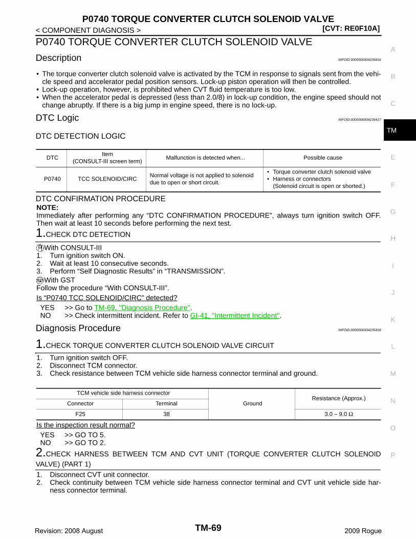
P0740 TORQUE CONVERTER CLUTCH SOLENOID VALVE[CVT: RE0F10A]
C
E
F
G
H
I
J
K
L
M
A
B
M
N
O
P
< COMPONENT DIAGNOSIS >
T
P0740 TORQUE CONVERTER CLUTCH SOLENOID VALVE
Description INFOID:0000000004235416
• The torque converter clutch solenoid valve is activated by the TCM in response to signals sent from the vehi-cle speed and accelerator pedal position sensors. Lock-up piston operation will then be controlled.
• Lock-up operation, however, is prohibited when CVT fluid temperature is too low.• When the accelerator pedal is depressed (less than 2.0/8) in lock-up condition, the engine speed should not
change abruptly. If there is a big jump in engine speed, there is no lock-up.
DTC Logic INFOID:0000000004235417
DTC DETECTION LOGIC
DTC CONFIRMATION PROCEDURENOTE:Immediately after performing any “DTC CONFIRMATION PROCEDURE”, always turn ignition switch OFF.Then wait at least 10 seconds before performing the next test.
1.CHECK DTC DETECTION
With CONSULT-III1. Turn ignition switch ON.2. Wait at least 10 consecutive seconds.3. Perform “Self Diagnostic Results” in “TRANSMISSION”.
With GSTFollow the procedure “With CONSULT-III”.Is “P0740 TCC SOLENOID/CIRC” detected?YES >> Go to TM-69, "Diagnosis Procedure".NO >> Check intermittent incident. Refer to GI-41, "Intermittent Incident".
Diagnosis Procedure INFOID:0000000004235418
1.CHECK TORQUE CONVERTER CLUTCH SOLENOID VALVE CIRCUIT
1. Turn ignition switch OFF.2. Disconnect TCM connector.3. Check resistance between TCM vehicle side harness connector terminal and ground.
Is the inspection result normal?YES >> GO TO 5.NO >> GO TO 2.
2.CHECK HARNESS BETWEEN TCM AND CVT UNIT (TORQUE CONVERTER CLUTCH SOLENOIDVALVE) (PART 1)
1. Disconnect CVT unit connector.2. Check continuity between TCM vehicle side harness connector terminal and CVT unit vehicle side har-
ness connector terminal.
DTCItem
(CONSULT-III screen term)Malfunction is detected when... Possible cause
P0740 TCC SOLENOID/CIRCNormal voltage is not applied to solenoid due to open or short circuit.
• Torque converter clutch solenoid valve• Harness or connectors
(Solenoid circuit is open or shorted.)
TCM vehicle side harness connector
GroundResistance (Approx.)
Connector Terminal
F25 38 3.0 – 9.0 Ω
TM-69Revision: 2008 August 2009 Rogue
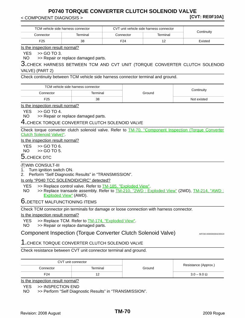
[CVT: RE0F10A]P0740 TORQUE CONVERTER CLUTCH SOLENOID VALVE
< COMPONENT DIAGNOSIS >
Is the inspection result normal?YES >> GO TO 3.NO >> Repair or replace damaged parts.
3.CHECK HARNESS BETWEEN TCM AND CVT UNIT (TORQUE CONVERTER CLUTCH SOLENOIDVALVE) (PART 2)
Check continuity between TCM vehicle side harness connector terminal and ground.
Is the inspection result normal?YES >> GO TO 4.NO >> Repair or replace damaged parts.
4.CHECK TORQUE CONVERTER CLUTCH SOLENOID VALVE
Check torque converter clutch solenoid valve. Refer to TM-70, "Component Inspection (Torque ConverterClutch Solenoid Valve)".Is the inspection result normal?YES >> GO TO 6.NO >> GO TO 5.
5.CHECK DTC
With CONSULT-III1. Turn ignition switch ON.2. Perform “Self Diagnostic Results” in “TRANSMISSION”.Is only “P040 TCC SOLENOID/CIRC” detected?YES >> Replace control valve. Refer to TM-185, "Exploded View".NO >> Replace transaxle assembly. Refer to TM-210, "2WD : Exploded View" (2WD), TM-214, "AWD :
Exploded View" (AWD).
6.DETECT MALFUNCTIONING ITEMS
Check TCM connector pin terminals for damage or loose connection with harness connector.Is the inspection result normal?YES >> Replace TCM. Refer to TM-174, "Exploded View".NO >> Repair or replace damaged parts.
Component Inspection (Torque Converter Clutch Solenoid Valve) INFOID:0000000004235419
1.CHECK TORQUE CONVERTER CLUTCH SOLENOID VALVE
Check resistance between CVT unit connector terminal and ground.
Is the inspection result normal?YES >> INSPECTION ENDNO >> Perform “Self Diagnostic Results” in “TRANSMISSION”.
TCM vehicle side harness connector CVT unit vehicle side harness connectorContinuity
Connector Terminal Connector Terminal
F25 38 F24 12 Existed
TCM vehicle side harness connector
GroundContinuity
Connector Terminal
F25 38 Not existed
CVT unit connector
GroundResistance (Approx.)
Connector Terminal
F24 12 3.0 – 9.0 Ω
TM-70Revision: 2008 August 2009 Rogue
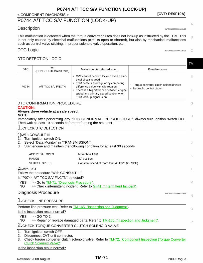
P0744 A/T TCC S/V FUNCTION (LOCK-UP)[CVT: RE0F10A]
C
E
F
G
H
I
J
K
L
M
A
B
M
N
O
P
< COMPONENT DIAGNOSIS >
T
P0744 A/T TCC S/V FUNCTION (LOCK-UP)
Description INFOID:0000000004235420
This malfunction is detected when the torque converter clutch does not lock-up as instructed by the TCM. Thisis not only caused by electrical malfunctions (circuits open or shorted), but also by mechanical malfunctionssuch as control valve sticking, improper solenoid valve operation, etc.
DTC Logic INFOID:0000000004235421
DTC DETECTION LOGIC
DTC CONFIRMATION PROCEDURECAUTION:Always drive vehicle at a safe speed.NOTE:Immediately after performing any “DTC CONFIRMATION PROCEDURE”, always turn ignition switch OFF.Then wait at least 10 seconds before performing the next test.
1.CHECK DTC DETECTION
With CONSULT-III1. Turn ignition switch ON.2. Select “Data Monitor” in “TRANSMISSION”.3. Start engine and maintain the following condition for at least 30 seconds.
With GSTFollow the procedure “With CONSULT-III”.Is “P0744 A/T TCC S/V FNCTN” detected?YES >> Go to TM-71, "Diagnosis Procedure".NO >> Check intermittent incident. Refer to GI-41, "Intermittent Incident".
Diagnosis Procedure INFOID:0000000004235422
1.CHECK LINE PRESSURE
Perform line pressure test. Refer to TM-165, "Inspection and Judgment".Is the inspection result normal?YES >> GO TO 2.NO >> Repair or replace damaged parts. Refer to TM-165, "Inspection and Judgment".
2.CHECK TORQUE CONVERTER CLUTCH SOLENOID VALVE
1. Turn ignition switch OFF.2. Disconnect CVT unit connector.3. Check torque converter clutch solenoid valve. Refer to TM-72, "Component Inspection (Torque Converter
Clutch Solenoid Valve)".Is the inspection result normal?
DTCItem
(CONSULT-III screen term)Malfunction is detected when... Possible cause
P0744 A/T TCC S/V FNCTN
• CVT cannot perform lock-up even if elec-trical circuit is good.
• TCM detects as irregular by comparing difference value with slip rotation.
• There is a big difference between engine speed and primary speed sensor when TCM lock-up signal is on.
• Torque converter clutch solenoid valve• Hydraulic control circuit
ACC PEDAL OPEN : More than 1.0/8
RANGE : “D” position
VEHICLE SPEED : Constant speed of more than 40 km/h (25 MPH)
TM-71Revision: 2008 August 2009 Rogue
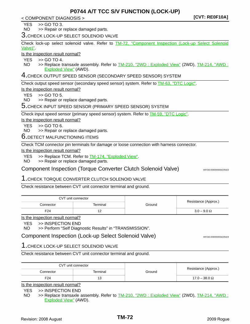
[CVT: RE0F10A]P0744 A/T TCC S/V FUNCTION (LOCK-UP)
< COMPONENT DIAGNOSIS >YES >> GO TO 3.NO >> Repair or replace damaged parts.
3.CHECK LOCK-UP SELECT SOLENOID VALVE
Check lock-up select solenoid valve. Refer to TM-72, "Component Inspection (Lock-up Select SolenoidValve)".Is the inspection result normal?YES >> GO TO 4.NO >> Replace transaxle assembly. Refer to TM-210, "2WD : Exploded View" (2WD), TM-214, "AWD :
Exploded View" (AWD).
4.CHECK OUTPUT SPEED SENSOR (SECONDARY SPEED SENSOR) SYSTEM
Check output speed sensor (secondary speed sensor) system. Refer to TM-63, "DTC Logic".Is the inspection result normal?YES >> GO TO 5.NO >> Repair or replace damaged parts.
5.CHECK INPUT SPEED SENSOR (PRIMARY SPEED SENSOR) SYSTEM
Check input speed sensor (primary speed sensor) system. Refer to TM-59, "DTC Logic".Is the inspection result normal?YES >> GO TO 6.NO >> Repair or replace damaged parts.
6.DETECT MALFUNCTIONING ITEMS
Check TCM connector pin terminals for damage or loose connection with harness connector.Is the inspection result normal?YES >> Replace TCM. Refer to TM-174, "Exploded View".NO >> Repair or replace damaged parts.
Component Inspection (Torque Converter Clutch Solenoid Valve) INFOID:0000000004235423
1.CHECK TORQUE CONVERTER CLUTCH SOLENOID VALVE
Check resistance between CVT unit connector terminal and ground.
Is the inspection result normal?YES >> INSPECTION ENDNO >> Perform “Self Diagnostic Results” in “TRANSMISSION”.
Component Inspection (Lock-up Select Solenoid Valve) INFOID:0000000004235424
1.CHECK LOCK-UP SELECT SOLENOID VALVE
Check resistance between CVT unit connector terminal and ground.
Is the inspection result normal?YES >> INSPECTION ENDNO >> Replace transaxle assembly. Refer to TM-210, "2WD : Exploded View" (2WD), TM-214, "AWD :
Exploded View" (AWD).
CVT unit connector
GroundResistance (Approx.)
Connector Terminal
F24 12 3.0 – 9.0 Ω
CVT unit connector
GroundResistance (Approx.)
Connector Terminal
F24 13 17.0 – 38.0 Ω
TM-72Revision: 2008 August 2009 Rogue

P0745 LINE PRESSURE SOLENOID VALVE[CVT: RE0F10A]
C
E
F
G
H
I
J
K
L
M
A
B
M
N
O
P
< COMPONENT DIAGNOSIS >
T
P0745 LINE PRESSURE SOLENOID VALVE
Description INFOID:0000000004235425
The pressure control solenoid valve A (line pressure solenoid valve) regulates the oil pump discharge pres-sure to suit the driving condition in response to a signal sent from the TCM.
DTC Logic INFOID:0000000004235426
DTC DETECTION LOGIC
DTC CONFIRMATION PROCEDURENOTE:Immediately after performing any “DTC CONFIRMATION PROCEDURE”, always turn ignition switch OFF.Then wait at least 10 seconds before performing the next test.
1.CHECK DTC DETECTION
With CONSULT-III1. Turn ignition switch ON.2. Start engine and wait at least 5 seconds.3. Perform “Self Diagnostic Results” in “TRANSMISSION”.
With GSTFollow the procedure “With CONSULT-III”.Is “P0745 L/PRESS SOL/CIRC” detected?YES >> Go to TM-73, "Diagnosis Procedure".NO >> Check intermittent incident. Refer to GI-41, "Intermittent Incident".
Diagnosis Procedure INFOID:0000000004235427
1.CHECK PRESSURE CONTROL SOLENOID VALVE A (LINE PRESSURE SOLENOID VALVE) CIRCUIT
1. Turn ignition switch OFF.2. Disconnect TCM connector.3. Check resistance between TCM vehicle side harness connector terminal and ground.
Is the inspection result normal?YES >> GO TO 5.NO >> GO TO 2.
2.CHECK HARNESS BETWEEN TCM AND CVT UNIT [PRESSURE CONTROL SOLENOID VALVE A (LINEPRESSURE SOLENOID VALVE)] (PART 1)
1. Disconnect CVT unit connector.2. Check continuity between TCM vehicle side harness connector terminal and CVT unit vehicle side har-
ness connector terminal.
DTCItem
(CONSULT-III screen term)Malfunction is detected when... Possible cause
P0745 L/PRESS SOL/CIRC
• Normal voltage is not applied to solenoid due to open or short circuit.
• TCM detects as irregular by comparing target value with monitor value.
• Harness or connectors(Solenoid circuit is open or shorted.)
• Pressure control solenoid valve A (line pressure solenoid valve)
TCM vehicle side harness connector
GroundResistance (Approx.)
Connector Terminal
F25 40 3.0 – 9.0 Ω
TCM vehicle side harness connector CVT unit vehicle side harness connectorContinuity
Connector Terminal Connector Terminal
F25 40 F24 2 Existed
TM-73Revision: 2008 August 2009 Rogue
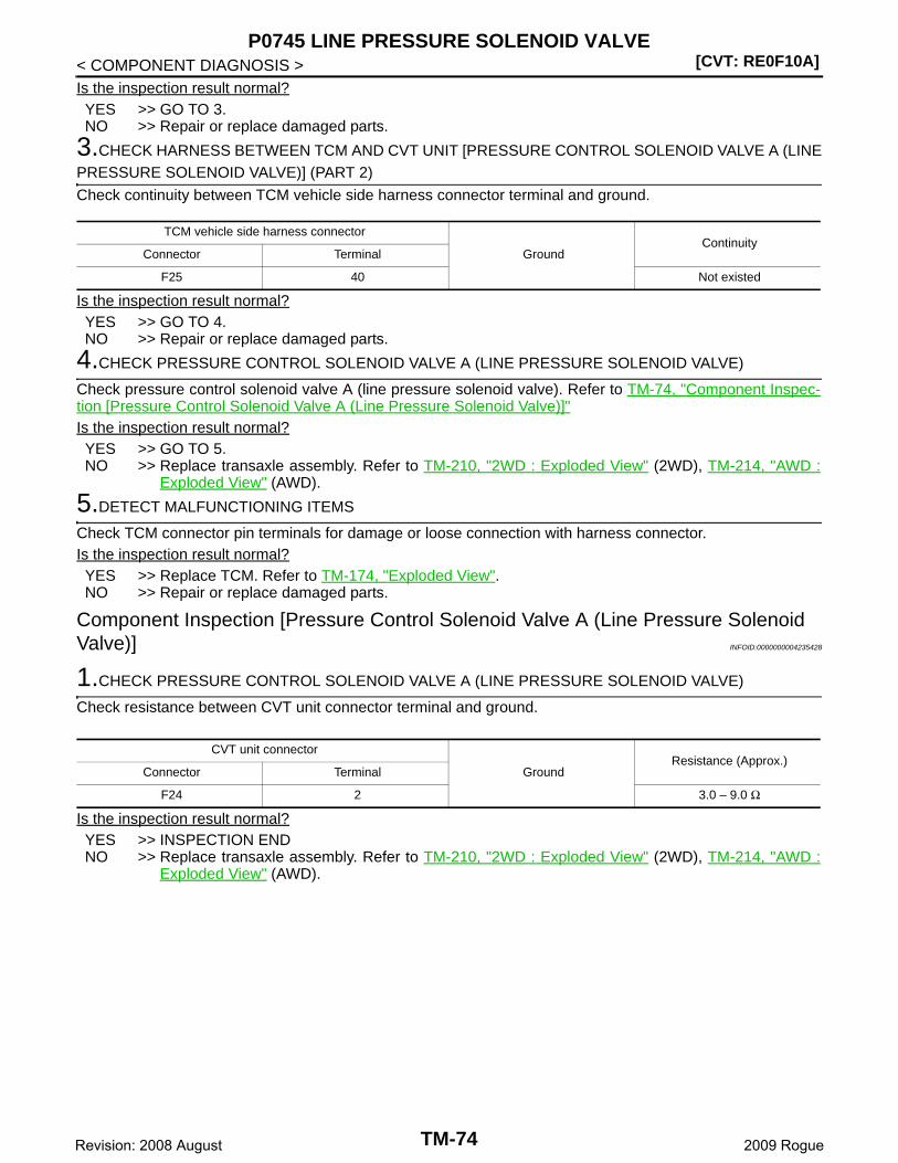
[CVT: RE0F10A]P0745 LINE PRESSURE SOLENOID VALVE
< COMPONENT DIAGNOSIS >Is the inspection result normal?YES >> GO TO 3.NO >> Repair or replace damaged parts.
3.CHECK HARNESS BETWEEN TCM AND CVT UNIT [PRESSURE CONTROL SOLENOID VALVE A (LINEPRESSURE SOLENOID VALVE)] (PART 2)
Check continuity between TCM vehicle side harness connector terminal and ground.
Is the inspection result normal?YES >> GO TO 4.NO >> Repair or replace damaged parts.
4.CHECK PRESSURE CONTROL SOLENOID VALVE A (LINE PRESSURE SOLENOID VALVE)
Check pressure control solenoid valve A (line pressure solenoid valve). Refer to TM-74, "Component Inspec-tion [Pressure Control Solenoid Valve A (Line Pressure Solenoid Valve)]"Is the inspection result normal?YES >> GO TO 5.NO >> Replace transaxle assembly. Refer to TM-210, "2WD : Exploded View" (2WD), TM-214, "AWD :
Exploded View" (AWD).
5.DETECT MALFUNCTIONING ITEMS
Check TCM connector pin terminals for damage or loose connection with harness connector.Is the inspection result normal?YES >> Replace TCM. Refer to TM-174, "Exploded View".NO >> Repair or replace damaged parts.
Component Inspection [Pressure Control Solenoid Valve A (Line Pressure Solenoid Valve)] INFOID:0000000004235428
1.CHECK PRESSURE CONTROL SOLENOID VALVE A (LINE PRESSURE SOLENOID VALVE)
Check resistance between CVT unit connector terminal and ground.
Is the inspection result normal?YES >> INSPECTION ENDNO >> Replace transaxle assembly. Refer to TM-210, "2WD : Exploded View" (2WD), TM-214, "AWD :
Exploded View" (AWD).
TCM vehicle side harness connector
GroundContinuity
Connector Terminal
F25 40 Not existed
CVT unit connector
GroundResistance (Approx.)
Connector Terminal
F24 2 3.0 – 9.0 Ω
TM-74Revision: 2008 August 2009 Rogue
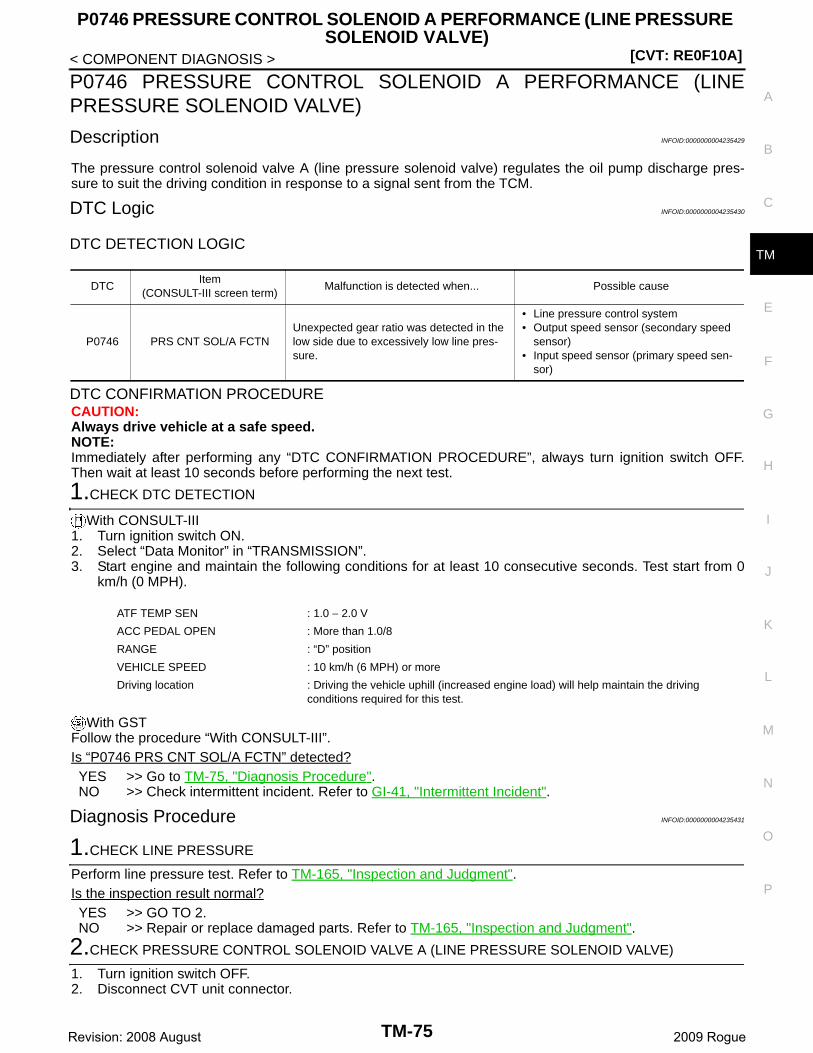
P0746 PRESSURE CONTROL SOLENOID A PERFORMANCE (LINE PRESSURE SOLENOID VALVE)
[CVT: RE0F10A]
C
E
F
G
H
I
J
K
L
M
A
B
M
N
O
P
< COMPONENT DIAGNOSIS >
T
P0746 PRESSURE CONTROL SOLENOID A PERFORMANCE (LINEPRESSURE SOLENOID VALVE)
Description INFOID:0000000004235429
The pressure control solenoid valve A (line pressure solenoid valve) regulates the oil pump discharge pres-sure to suit the driving condition in response to a signal sent from the TCM.
DTC Logic INFOID:0000000004235430
DTC DETECTION LOGIC
DTC CONFIRMATION PROCEDURECAUTION:Always drive vehicle at a safe speed.NOTE:Immediately after performing any “DTC CONFIRMATION PROCEDURE”, always turn ignition switch OFF.Then wait at least 10 seconds before performing the next test.
1.CHECK DTC DETECTION
With CONSULT-III1. Turn ignition switch ON.2. Select “Data Monitor” in “TRANSMISSION”.3. Start engine and maintain the following conditions for at least 10 consecutive seconds. Test start from 0
km/h (0 MPH).
With GSTFollow the procedure “With CONSULT-III”.Is “P0746 PRS CNT SOL/A FCTN” detected?YES >> Go to TM-75, "Diagnosis Procedure".NO >> Check intermittent incident. Refer to GI-41, "Intermittent Incident".
Diagnosis Procedure INFOID:0000000004235431
1.CHECK LINE PRESSURE
Perform line pressure test. Refer to TM-165, "Inspection and Judgment".Is the inspection result normal?YES >> GO TO 2.NO >> Repair or replace damaged parts. Refer to TM-165, "Inspection and Judgment".
2.CHECK PRESSURE CONTROL SOLENOID VALVE A (LINE PRESSURE SOLENOID VALVE)
1. Turn ignition switch OFF.2. Disconnect CVT unit connector.
DTCItem
(CONSULT-III screen term)Malfunction is detected when... Possible cause
P0746 PRS CNT SOL/A FCTNUnexpected gear ratio was detected in the low side due to excessively low line pres-sure.
• Line pressure control system• Output speed sensor (secondary speed
sensor)• Input speed sensor (primary speed sen-
sor)
ATF TEMP SEN : 1.0 − 2.0 V
ACC PEDAL OPEN : More than 1.0/8
RANGE : “D” position
VEHICLE SPEED : 10 km/h (6 MPH) or more
Driving location : Driving the vehicle uphill (increased engine load) will help maintain the driving conditions required for this test.
TM-75Revision: 2008 August 2009 Rogue
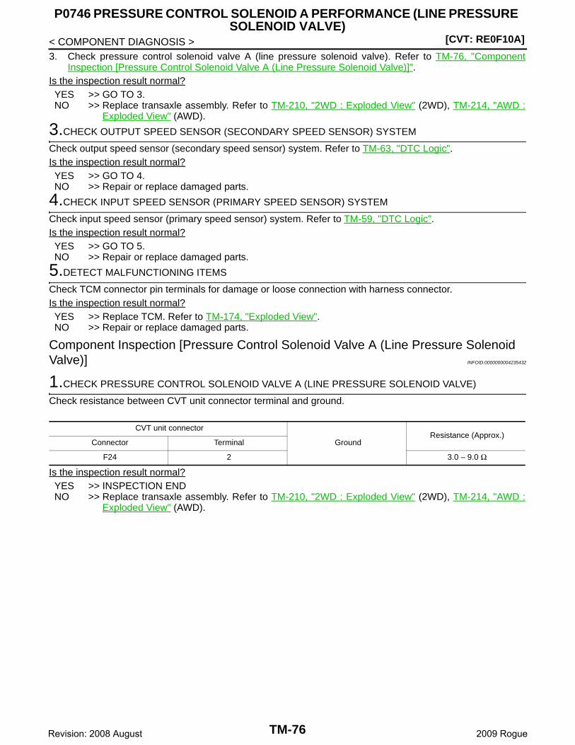
[CVT: RE0F10A]
P0746 PRESSURE CONTROL SOLENOID A PERFORMANCE (LINE PRESSURE SOLENOID VALVE)
< COMPONENT DIAGNOSIS >3. Check pressure control solenoid valve A (line pressure solenoid valve). Refer to TM-76, "Component
Inspection [Pressure Control Solenoid Valve A (Line Pressure Solenoid Valve)]".Is the inspection result normal?YES >> GO TO 3.NO >> Replace transaxle assembly. Refer to TM-210, "2WD : Exploded View" (2WD), TM-214, "AWD :
Exploded View" (AWD).
3.CHECK OUTPUT SPEED SENSOR (SECONDARY SPEED SENSOR) SYSTEM
Check output speed sensor (secondary speed sensor) system. Refer to TM-63, "DTC Logic".Is the inspection result normal?YES >> GO TO 4.NO >> Repair or replace damaged parts.
4.CHECK INPUT SPEED SENSOR (PRIMARY SPEED SENSOR) SYSTEM
Check input speed sensor (primary speed sensor) system. Refer to TM-59, "DTC Logic".Is the inspection result normal?YES >> GO TO 5.NO >> Repair or replace damaged parts.
5.DETECT MALFUNCTIONING ITEMS
Check TCM connector pin terminals for damage or loose connection with harness connector.Is the inspection result normal?YES >> Replace TCM. Refer to TM-174, "Exploded View".NO >> Repair or replace damaged parts.
Component Inspection [Pressure Control Solenoid Valve A (Line Pressure Solenoid Valve)] INFOID:0000000004235432
1.CHECK PRESSURE CONTROL SOLENOID VALVE A (LINE PRESSURE SOLENOID VALVE)
Check resistance between CVT unit connector terminal and ground.
Is the inspection result normal?YES >> INSPECTION ENDNO >> Replace transaxle assembly. Refer to TM-210, "2WD : Exploded View" (2WD), TM-214, "AWD :
Exploded View" (AWD).
CVT unit connector
GroundResistance (Approx.)
Connector Terminal
F24 2 3.0 – 9.0 Ω
TM-76Revision: 2008 August 2009 Rogue
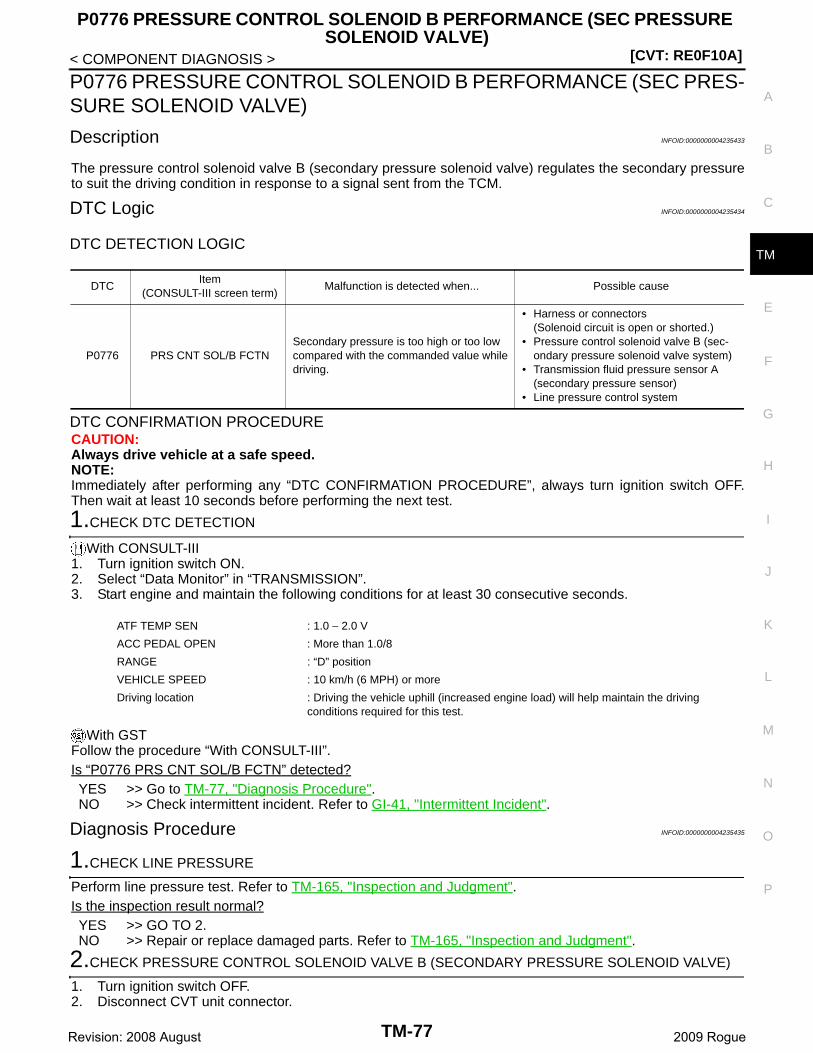
P0776 PRESSURE CONTROL SOLENOID B PERFORMANCE (SEC PRESSURE SOLENOID VALVE)
[CVT: RE0F10A]
C
E
F
G
H
I
J
K
L
M
A
B
M
N
O
P
< COMPONENT DIAGNOSIS >
T
P0776 PRESSURE CONTROL SOLENOID B PERFORMANCE (SEC PRES-SURE SOLENOID VALVE)
Description INFOID:0000000004235433
The pressure control solenoid valve B (secondary pressure solenoid valve) regulates the secondary pressureto suit the driving condition in response to a signal sent from the TCM.
DTC Logic INFOID:0000000004235434
DTC DETECTION LOGIC
DTC CONFIRMATION PROCEDURECAUTION:Always drive vehicle at a safe speed.NOTE:Immediately after performing any “DTC CONFIRMATION PROCEDURE”, always turn ignition switch OFF.Then wait at least 10 seconds before performing the next test.
1.CHECK DTC DETECTION
With CONSULT-III1. Turn ignition switch ON.2. Select “Data Monitor” in “TRANSMISSION”.3. Start engine and maintain the following conditions for at least 30 consecutive seconds.
With GSTFollow the procedure “With CONSULT-III”.Is “P0776 PRS CNT SOL/B FCTN” detected?YES >> Go to TM-77, "Diagnosis Procedure".NO >> Check intermittent incident. Refer to GI-41, "Intermittent Incident".
Diagnosis Procedure INFOID:0000000004235435
1.CHECK LINE PRESSURE
Perform line pressure test. Refer to TM-165, "Inspection and Judgment".Is the inspection result normal?YES >> GO TO 2.NO >> Repair or replace damaged parts. Refer to TM-165, "Inspection and Judgment".
2.CHECK PRESSURE CONTROL SOLENOID VALVE B (SECONDARY PRESSURE SOLENOID VALVE)
1. Turn ignition switch OFF.2. Disconnect CVT unit connector.
DTCItem
(CONSULT-III screen term)Malfunction is detected when... Possible cause
P0776 PRS CNT SOL/B FCTNSecondary pressure is too high or too low compared with the commanded value while driving.
• Harness or connectors(Solenoid circuit is open or shorted.)
• Pressure control solenoid valve B (sec-ondary pressure solenoid valve system)
• Transmission fluid pressure sensor A (secondary pressure sensor)
• Line pressure control system
ATF TEMP SEN : 1.0 − 2.0 V
ACC PEDAL OPEN : More than 1.0/8
RANGE : “D” position
VEHICLE SPEED : 10 km/h (6 MPH) or more
Driving location : Driving the vehicle uphill (increased engine load) will help maintain the driving conditions required for this test.
TM-77Revision: 2008 August 2009 Rogue
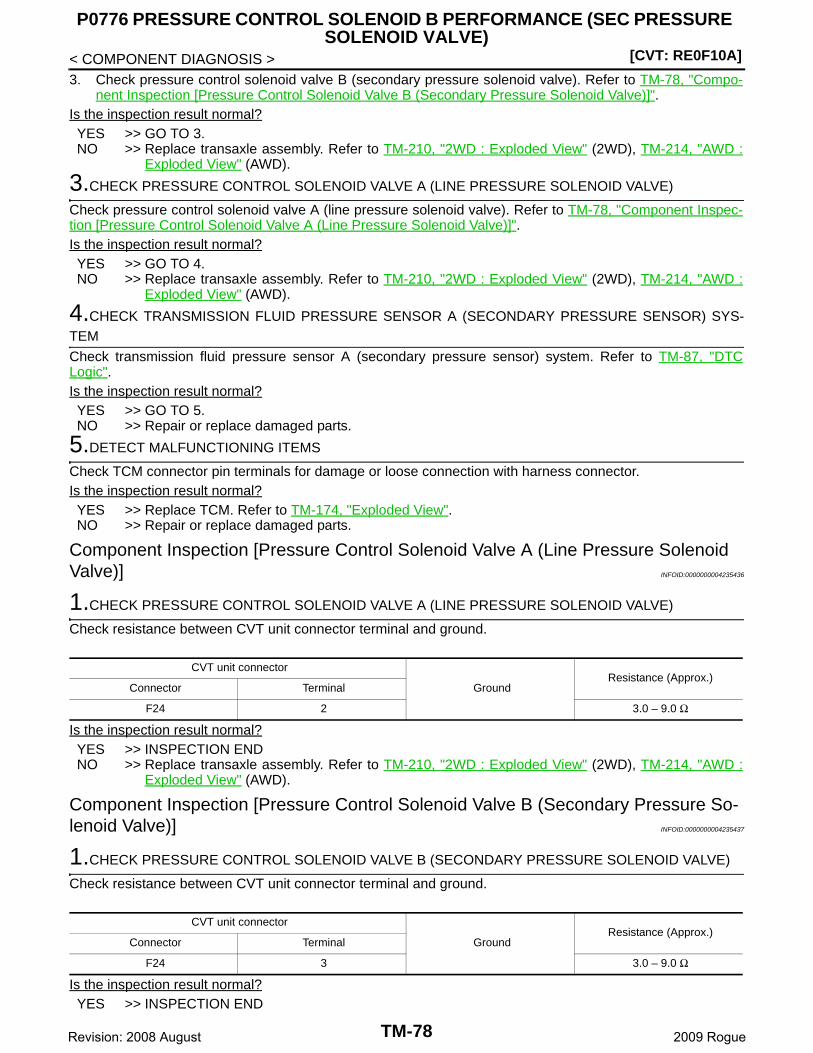
[CVT: RE0F10A]
P0776 PRESSURE CONTROL SOLENOID B PERFORMANCE (SEC PRESSURE SOLENOID VALVE)
< COMPONENT DIAGNOSIS >3. Check pressure control solenoid valve B (secondary pressure solenoid valve). Refer to TM-78, "Compo-
nent Inspection [Pressure Control Solenoid Valve B (Secondary Pressure Solenoid Valve)]".Is the inspection result normal?YES >> GO TO 3.NO >> Replace transaxle assembly. Refer to TM-210, "2WD : Exploded View" (2WD), TM-214, "AWD :
Exploded View" (AWD).
3.CHECK PRESSURE CONTROL SOLENOID VALVE A (LINE PRESSURE SOLENOID VALVE)
Check pressure control solenoid valve A (line pressure solenoid valve). Refer to TM-78, "Component Inspec-tion [Pressure Control Solenoid Valve A (Line Pressure Solenoid Valve)]".Is the inspection result normal?YES >> GO TO 4.NO >> Replace transaxle assembly. Refer to TM-210, "2WD : Exploded View" (2WD), TM-214, "AWD :
Exploded View" (AWD).
4.CHECK TRANSMISSION FLUID PRESSURE SENSOR A (SECONDARY PRESSURE SENSOR) SYS-TEM
Check transmission fluid pressure sensor A (secondary pressure sensor) system. Refer to TM-87, "DTCLogic".Is the inspection result normal?YES >> GO TO 5.NO >> Repair or replace damaged parts.
5.DETECT MALFUNCTIONING ITEMS
Check TCM connector pin terminals for damage or loose connection with harness connector.Is the inspection result normal?YES >> Replace TCM. Refer to TM-174, "Exploded View".NO >> Repair or replace damaged parts.
Component Inspection [Pressure Control Solenoid Valve A (Line Pressure Solenoid Valve)] INFOID:0000000004235436
1.CHECK PRESSURE CONTROL SOLENOID VALVE A (LINE PRESSURE SOLENOID VALVE)
Check resistance between CVT unit connector terminal and ground.
Is the inspection result normal?YES >> INSPECTION ENDNO >> Replace transaxle assembly. Refer to TM-210, "2WD : Exploded View" (2WD), TM-214, "AWD :
Exploded View" (AWD).
Component Inspection [Pressure Control Solenoid Valve B (Secondary Pressure So-lenoid Valve)] INFOID:0000000004235437
1.CHECK PRESSURE CONTROL SOLENOID VALVE B (SECONDARY PRESSURE SOLENOID VALVE)
Check resistance between CVT unit connector terminal and ground.
Is the inspection result normal?YES >> INSPECTION END
CVT unit connector
GroundResistance (Approx.)
Connector Terminal
F24 2 3.0 – 9.0 Ω
CVT unit connector
GroundResistance (Approx.)
Connector Terminal
F24 3 3.0 – 9.0 Ω
TM-78Revision: 2008 August 2009 Rogue
P0776 PRESSURE CONTROL SOLENOID B PERFORMANCE (SEC PRESSURE SOLENOID VALVE)
[CVT: RE0F10A]
C
E
F
G
H
I
J
K
L
M
A
B
M
N
O
P
< COMPONENT DIAGNOSIS >
T
NO >> Replace transaxle assembly. Refer to TM-210, "2WD : Exploded View" (2WD), TM-214, "AWD :Exploded View" (AWD).
TM-79Revision: 2008 August 2009 Rogue
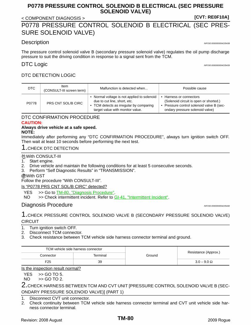
[CVT: RE0F10A]
P0778 PRESSURE CONTROL SOLENOID B ELECTRICAL (SEC PRESSURE SOLENOID VALVE)
< COMPONENT DIAGNOSIS >
P0778 PRESSURE CONTROL SOLENOID B ELECTRICAL (SEC PRES-SURE SOLENOID VALVE)
Description INFOID:0000000004235438
The pressure control solenoid valve B (secondary pressure solenoid valve) regulates the oil pump dischargepressure to suit the driving condition in response to a signal sent from the TCM.
DTC Logic INFOID:0000000004235439
DTC DETECTION LOGIC
DTC CONFIRMATION PROCEDURECAUTION:Always drive vehicle at a safe speed.NOTE:Immediately after performing any “DTC CONFIRMATION PROCEDURE”, always turn ignition switch OFF.Then wait at least 10 seconds before performing the next test.
1.CHECK DTC DETECTION
With CONSULT-III1. Start engine.2. Drive vehicle and maintain the following conditions for at least 5 consecutive seconds.3. Perform “Self Diagnostic Results” in “TRANSMISSION”.
With GSTFollow the procedure “With CONSULT-III”.Is “P0778 PRS CNT SOL/B CIRC” detected?YES >> Go to TM-80, "Diagnosis Procedure".NO >> Check intermittent incident. Refer to GI-41, "Intermittent Incident".
Diagnosis Procedure INFOID:0000000004235440
1.CHECK PRESSURE CONTROL SOLENOID VALVE B (SECONDARY PRESSURE SOLENOID VALVE)CIRCUIT
1. Turn ignition switch OFF.2. Disconnect TCM connector.3. Check resistance between TCM vehicle side harness connector terminal and ground.
Is the inspection result normal?YES >> GO TO 5.NO >> GO TO 2.
2.CHECK HARNESS BETWEEN TCM AND CVT UNIT [PRESSURE CONTROL SOLENOID VALVE B (SEC-ONDARY PRESSURE SOLENOID VALVE)] (PART 1)
1. Disconnect CVT unit connector.2. Check continuity between TCM vehicle side harness connector terminal and CVT unit vehicle side har-
ness connector terminal.
DTCItem
(CONSULT-III screen term)Malfunction is detected when... Possible cause
P0778 PRS CNT SOL/B CIRC
• Normal voltage is not applied to solenoid due to cut line, short, etc.
• TCM detects as irregular by comparing target value with monitor value.
• Harness or connectors(Solenoid circuit is open or shorted.)
• Pressure control solenoid valve B (sec-ondary pressure solenoid valve)
TCM vehicle side harness connector
GroundResistance (Approx.)
Connector Terminal
F25 39 3.0 – 9.0 Ω
TM-80Revision: 2008 August 2009 Rogue
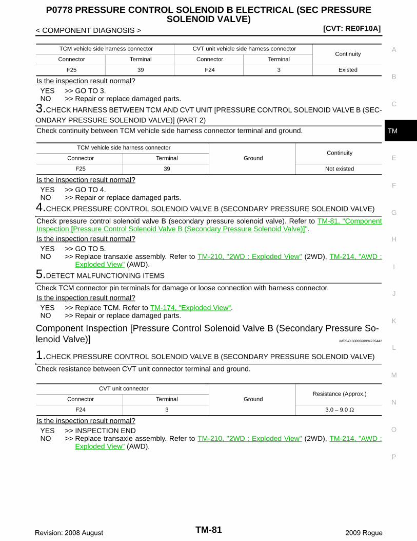
P0778 PRESSURE CONTROL SOLENOID B ELECTRICAL (SEC PRESSURE SOLENOID VALVE)
[CVT: RE0F10A]
C
E
F
G
H
I
J
K
L
M
A
B
M
N
O
P
< COMPONENT DIAGNOSIS >
T
Is the inspection result normal?YES >> GO TO 3.NO >> Repair or replace damaged parts.
3.CHECK HARNESS BETWEEN TCM AND CVT UNIT [PRESSURE CONTROL SOLENOID VALVE B (SEC-ONDARY PRESSURE SOLENOID VALVE)] (PART 2)
Check continuity between TCM vehicle side harness connector terminal and ground.
Is the inspection result normal?YES >> GO TO 4.NO >> Repair or replace damaged parts.
4.CHECK PRESSURE CONTROL SOLENOID VALVE B (SECONDARY PRESSURE SOLENOID VALVE)
Check pressure control solenoid valve B (secondary pressure solenoid valve). Refer to TM-81, "ComponentInspection [Pressure Control Solenoid Valve B (Secondary Pressure Solenoid Valve)]".Is the inspection result normal?YES >> GO TO 5.NO >> Replace transaxle assembly. Refer to TM-210, "2WD : Exploded View" (2WD), TM-214, "AWD :
Exploded View" (AWD).
5.DETECT MALFUNCTIONING ITEMS
Check TCM connector pin terminals for damage or loose connection with harness connector.Is the inspection result normal?YES >> Replace TCM. Refer to TM-174, "Exploded View".NO >> Repair or replace damaged parts.
Component Inspection [Pressure Control Solenoid Valve B (Secondary Pressure So-lenoid Valve)] INFOID:0000000004235441
1.CHECK PRESSURE CONTROL SOLENOID VALVE B (SECONDARY PRESSURE SOLENOID VALVE)
Check resistance between CVT unit connector terminal and ground.
Is the inspection result normal?YES >> INSPECTION ENDNO >> Replace transaxle assembly. Refer to TM-210, "2WD : Exploded View" (2WD), TM-214, "AWD :
Exploded View" (AWD).
TCM vehicle side harness connector CVT unit vehicle side harness connectorContinuity
Connector Terminal Connector Terminal
F25 39 F24 3 Existed
TCM vehicle side harness connector
GroundContinuity
Connector Terminal
F25 39 Not existed
CVT unit connector
GroundResistance (Approx.)
Connector Terminal
F24 3 3.0 – 9.0 Ω
TM-81Revision: 2008 August 2009 Rogue

[CVT: RE0F10A]P0826 MANUAL MODE SWITCH
< COMPONENT DIAGNOSIS >
P0826 MANUAL MODE SWITCH
Description INFOID:0000000004235442
Manual mode switch is installed in control device.Manual mode switch transmits signals (manual mode, not manual mode, shift up and shift down) to combina-tion meter.Paddle shifter is included in steering wheel.Paddle shifter transmits signals (shift up and shift down) to combination meter.Combination meter transmits signals (manual mode, not manual mode, shift up and shift down) to TCM withCAN communication signal.
DTC Logic INFOID:0000000004235443
DTC DETECTION LOGIC
DTC CONFIRMATION PROCEDURECAUTION:Always drive vehicle at a safe speed.NOTE:Immediately after performing any “DTC CONFIRMATION PROCEDURE”, always turn ignition switch OFF.Then wait at least 10 seconds before performing the next test.
1.CHECK DTC DETECTION
With CONSULT-III1. Turn ignition switch ON.2. Select “Data Monitor” in “TRANSMISSION”.3. Drive vehicle and maintain the following conditions for at least 60 consecutive seconds.
Is “P0826 MANUAL MODE SWITCH” detected?YES >> Go to TM-82, "Diagnosis Procedure".NO >> Check intermittent incident. Refer to GI-41, "Intermittent Incident".
Diagnosis Procedure INFOID:0000000004235444
1.CHECK MANUAL MODE SWITCH SIGNALS
With CONSULT-III1. Turn ignition switch ON.2. Select “Data Monitor” in “TRANSMISSION”.3. Check the ON/OFF operations of each monitor item.
DTCItem
(CONSULT-III screen term)Malfunction is detected when... Possible cause
P0826 MANUAL MODE SWITCH
• When an impossible pattern of switch sig-nals is detected, a malfunction is detect-ed.
• When shift up/down signal of paddle shifter continuously remains ON for 60 seconds.
• Harness or connectors- (The circuit of these switches are open or
shorted.)- (TCM, and combination meter circuit are
open or shorted.)- (CAN communication line is open or
shorted.)• Manual mode select switch (Built into con-
trol device)• Manual mode position select switch (Built
into control device)• Paddle shifter
MMODE : On
TM-82Revision: 2008 August 2009 Rogue
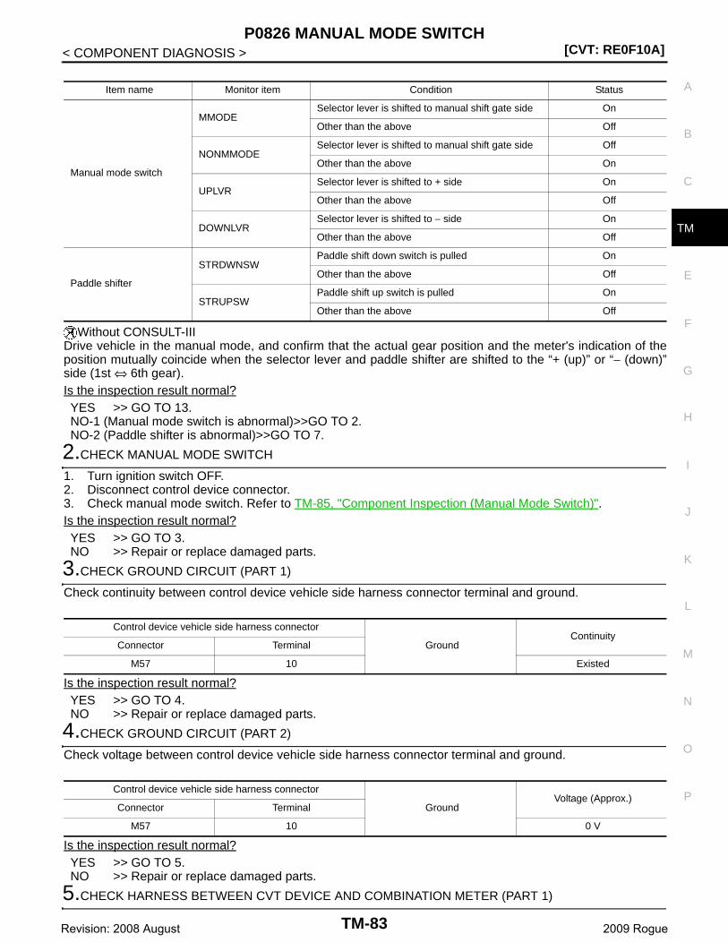
P0826 MANUAL MODE SWITCH[CVT: RE0F10A]
C
E
F
G
H
I
J
K
L
M
A
B
M
N
O
P
< COMPONENT DIAGNOSIS >
T
Without CONSULT-IIIDrive vehicle in the manual mode, and confirm that the actual gear position and the meter's indication of theposition mutually coincide when the selector lever and paddle shifter are shifted to the “+ (up)” or “− (down)”side (1st ⇔ 6th gear).Is the inspection result normal?YES >> GO TO 13.NO-1 (Manual mode switch is abnormal)>>GO TO 2.NO-2 (Paddle shifter is abnormal)>>GO TO 7.
2.CHECK MANUAL MODE SWITCH
1. Turn ignition switch OFF.2. Disconnect control device connector.3. Check manual mode switch. Refer to TM-85, "Component Inspection (Manual Mode Switch)".Is the inspection result normal?YES >> GO TO 3.NO >> Repair or replace damaged parts.
3.CHECK GROUND CIRCUIT (PART 1)
Check continuity between control device vehicle side harness connector terminal and ground.
Is the inspection result normal?YES >> GO TO 4.NO >> Repair or replace damaged parts.
4.CHECK GROUND CIRCUIT (PART 2)
Check voltage between control device vehicle side harness connector terminal and ground.
Is the inspection result normal?YES >> GO TO 5.NO >> Repair or replace damaged parts.
5.CHECK HARNESS BETWEEN CVT DEVICE AND COMBINATION METER (PART 1)
Item name Monitor item Condition Status
Manual mode switch
MMODESelector lever is shifted to manual shift gate side On
Other than the above Off
NONMMODESelector lever is shifted to manual shift gate side Off
Other than the above On
UPLVRSelector lever is shifted to + side On
Other than the above Off
DOWNLVRSelector lever is shifted to − side On
Other than the above Off
Paddle shifter
STRDWNSWPaddle shift down switch is pulled On
Other than the above Off
STRUPSWPaddle shift up switch is pulled On
Other than the above Off
Control device vehicle side harness connector
GroundContinuity
Connector Terminal
M57 10 Existed
Control device vehicle side harness connector
GroundVoltage (Approx.)
Connector Terminal
M57 10 0 V
TM-83Revision: 2008 August 2009 Rogue
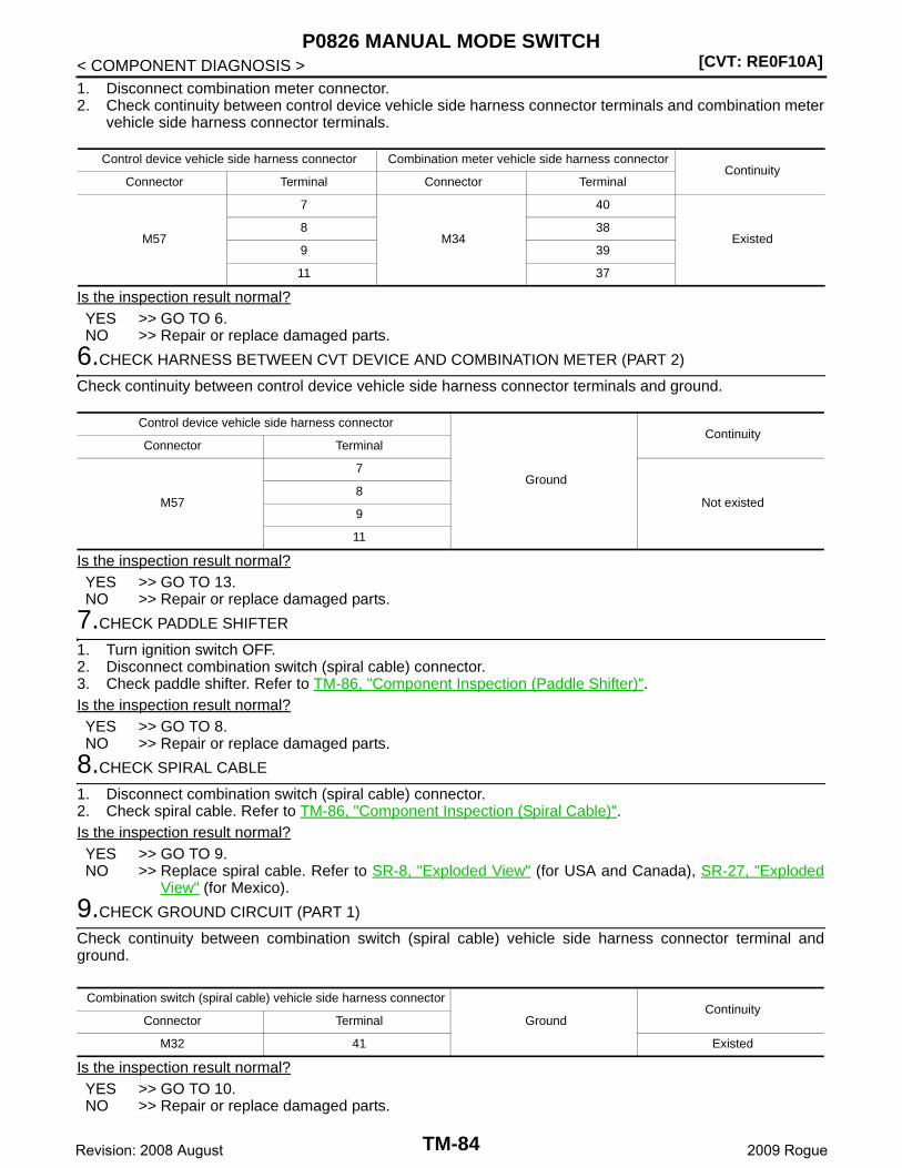
[CVT: RE0F10A]P0826 MANUAL MODE SWITCH
< COMPONENT DIAGNOSIS >1. Disconnect combination meter connector.2. Check continuity between control device vehicle side harness connector terminals and combination meter
vehicle side harness connector terminals.
Is the inspection result normal?YES >> GO TO 6.NO >> Repair or replace damaged parts.
6.CHECK HARNESS BETWEEN CVT DEVICE AND COMBINATION METER (PART 2)
Check continuity between control device vehicle side harness connector terminals and ground.
Is the inspection result normal?YES >> GO TO 13.NO >> Repair or replace damaged parts.
7.CHECK PADDLE SHIFTER
1. Turn ignition switch OFF.2. Disconnect combination switch (spiral cable) connector.3. Check paddle shifter. Refer to TM-86, "Component Inspection (Paddle Shifter)".Is the inspection result normal?YES >> GO TO 8.NO >> Repair or replace damaged parts.
8.CHECK SPIRAL CABLE
1. Disconnect combination switch (spiral cable) connector.2. Check spiral cable. Refer to TM-86, "Component Inspection (Spiral Cable)".Is the inspection result normal?YES >> GO TO 9.NO >> Replace spiral cable. Refer to SR-8, "Exploded View" (for USA and Canada), SR-27, "Exploded
View" (for Mexico).
9.CHECK GROUND CIRCUIT (PART 1)
Check continuity between combination switch (spiral cable) vehicle side harness connector terminal andground.
Is the inspection result normal?YES >> GO TO 10.NO >> Repair or replace damaged parts.
Control device vehicle side harness connector Combination meter vehicle side harness connectorContinuity
Connector Terminal Connector Terminal
M57
7
M34
40
Existed8 38
9 39
11 37
Control device vehicle side harness connector
Ground
ContinuityConnector Terminal
M57
7
Not existed8
9
11
Combination switch (spiral cable) vehicle side harness connector
GroundContinuity
Connector Terminal
M32 41 Existed
TM-84Revision: 2008 August 2009 Rogue

P0826 MANUAL MODE SWITCH[CVT: RE0F10A]
C
E
F
G
H
I
J
K
L
M
A
B
M
N
O
P
< COMPONENT DIAGNOSIS >
T
10.CHECK GROUND CIRCUIT (PART 2)
Check voltage between combination switch (spiral cable) vehicle side harness connector terminal and ground.
Is the inspection result normal?YES >> GO TO 11.NO >> Repair or replace damaged parts.
11.CHECK HARNESS BETWEEN SPIRAL CABLE AND COMBINATION METER (PART 1)
1. Disconnect combination meter connector.2. Check continuity between combination switch (spiral cable) vehicle side harness connector terminals and
combination meter vehicle side harness connector terminals.
Is the inspection result normal?YES >> GO TO 12.NO >> Repair or replace damaged parts.
12.CHECK HARNESS BETWEEN SPIRAL CABLE AND COMBINATION METER (PART 2)
Check continuity between combination switch (spiral cable) vehicle side harness connector terminals andground.
Is the inspection result normal?YES >> GO TO 13.NO >> Repair or replace damaged parts.
13.DETECT MALFUNCTIONING ITEMS
Check TCM connector pin terminals for damage or loose connection with harness connector.Is the inspection result normal?YES >> Replace TCM. Refer to TM-174, "Exploded View".NO >> Repair or replace damaged parts.
Component Inspection (Manual Mode Switch) INFOID:0000000004235445
1.CHECK MANUAL MODE SWITCH
Check continuity between control device connector terminals.
Combination switch (spiral cable) vehicle side harness connector
GroundVoltage (Approx.)
Connector Terminal
M32 41 0 V
Combination switch (spiral cable) vehicle side har-ness connector
Combination meter vehicle side harness connectorContinuity
Connector Terminal Connector Terminal
M3240
M3412
Existed42 14
Combination switch (spiral cable) vehicle side harness connector
Ground
ContinuityConnector Terminal
M3240
Not existed42
TM-85Revision: 2008 August 2009 Rogue

[CVT: RE0F10A]P0826 MANUAL MODE SWITCH
< COMPONENT DIAGNOSIS >
Is the inspection result normal?YES >> INSPECTION ENDNO >> Repair or replace damaged parts.
Component Inspection (Paddle Shifter) INFOID:0000000004235446
1.CHECK PADDLE SHIFTER
Check continuity between combination switch (spiral cable) connector terminals.
Is the inspection result normal?YES >> INSPECTION ENDNO >> Repair or replace damaged parts.
Component Inspection (Spiral Cable) INFOID:0000000004235447
1.CHECK SPIRAL CABLE
Check continuity between combination switch (spiral cable) connector terminals.
Is the inspection result normal?YES >> INSPECTION ENDNO >> Replace spiral cable. Refer to SR-8, "Exploded View" (for USA and Canada), SR-27, "Exploded
View" (for Mexico).
Control device connectorCondition Continuity
Connector Terminal
M57
10 11Selector lever is shifted to manual shift gate side Not existed
Other than the above Existed
7 10Selector lever is shifted to manual shift gate side Existed
Other than the above Not existed
9 10Selector lever is shifted to + side Existed
Other than the above Not existed
8 10Selector lever is shifted to − side Existed
Other than the above Not existed
Combination switch (spiral cable) connectorCondition Continuity
Connector Terminal
M353
9 8Paddle shift up switch is pulled Existed
Other than the above Not existed
7 8Paddle shift down switch is pulled Existed
Other than the above Not existed
Combination switch (spiral cable) connectorContinuity
Connector Terminal Connector Terminal
M32
40
M353
7
Existed41 8
42 9
TM-86Revision: 2008 August 2009 Rogue
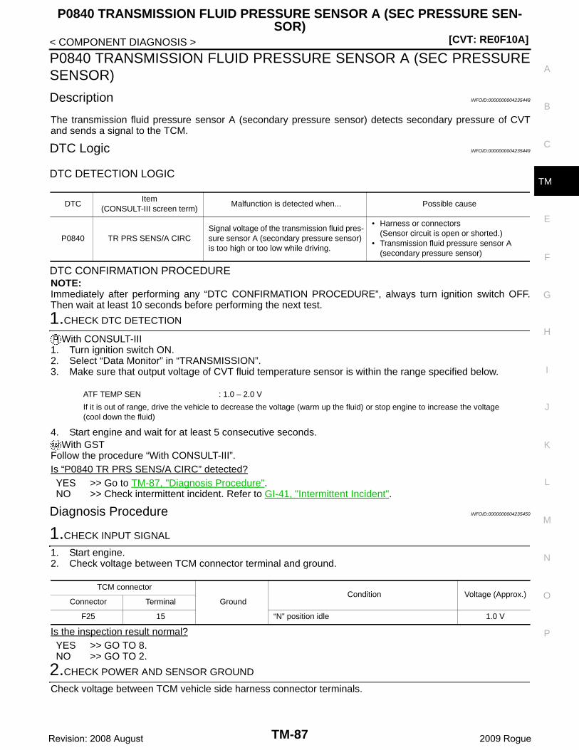
P0840 TRANSMISSION FLUID PRESSURE SENSOR A (SEC PRESSURE SEN-SOR)
[CVT: RE0F10A]
C
E
F
G
H
I
J
K
L
M
A
B
M
N
O
P
< COMPONENT DIAGNOSIS >
T
P0840 TRANSMISSION FLUID PRESSURE SENSOR A (SEC PRESSURESENSOR)
Description INFOID:0000000004235448
The transmission fluid pressure sensor A (secondary pressure sensor) detects secondary pressure of CVTand sends a signal to the TCM.
DTC Logic INFOID:0000000004235449
DTC DETECTION LOGIC
DTC CONFIRMATION PROCEDURENOTE:Immediately after performing any “DTC CONFIRMATION PROCEDURE”, always turn ignition switch OFF.Then wait at least 10 seconds before performing the next test.
1.CHECK DTC DETECTION
With CONSULT-III1. Turn ignition switch ON.2. Select “Data Monitor” in “TRANSMISSION”.3. Make sure that output voltage of CVT fluid temperature sensor is within the range specified below.
4. Start engine and wait for at least 5 consecutive seconds.With GST
Follow the procedure “With CONSULT-III”.Is “P0840 TR PRS SENS/A CIRC” detected?YES >> Go to TM-87, "Diagnosis Procedure".NO >> Check intermittent incident. Refer to GI-41, "Intermittent Incident".
Diagnosis Procedure INFOID:0000000004235450
1.CHECK INPUT SIGNAL
1. Start engine.2. Check voltage between TCM connector terminal and ground.
Is the inspection result normal?YES >> GO TO 8.NO >> GO TO 2.
2.CHECK POWER AND SENSOR GROUND
Check voltage between TCM vehicle side harness connector terminals.
DTCItem
(CONSULT-III screen term)Malfunction is detected when... Possible cause
P0840 TR PRS SENS/A CIRCSignal voltage of the transmission fluid pres-sure sensor A (secondary pressure sensor) is too high or too low while driving.
• Harness or connectors(Sensor circuit is open or shorted.)
• Transmission fluid pressure sensor A (secondary pressure sensor)
ATF TEMP SEN : 1.0 – 2.0 V
If it is out of range, drive the vehicle to decrease the voltage (warm up the fluid) or stop engine to increase the voltage (cool down the fluid)
TCM connector
GroundCondition Voltage (Approx.)
Connector Terminal
F25 15 “N” position idle 1.0 V
TM-87Revision: 2008 August 2009 Rogue
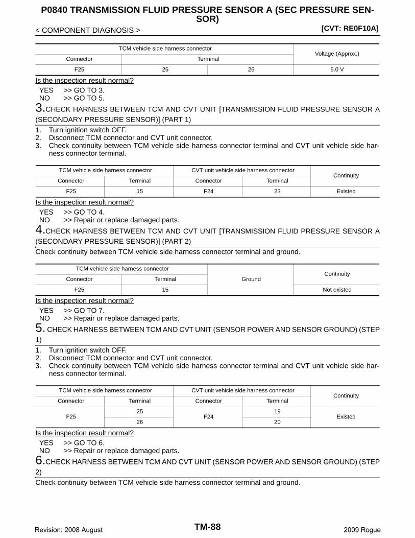
[CVT: RE0F10A]
P0840 TRANSMISSION FLUID PRESSURE SENSOR A (SEC PRESSURE SEN-SOR)
< COMPONENT DIAGNOSIS >
Is the inspection result normal?YES >> GO TO 3.NO >> GO TO 5.
3.CHECK HARNESS BETWEEN TCM AND CVT UNIT [TRANSMISSION FLUID PRESSURE SENSOR A(SECONDARY PRESSURE SENSOR)] (PART 1)
1. Turn ignition switch OFF.2. Disconnect TCM connector and CVT unit connector.3. Check continuity between TCM vehicle side harness connector terminal and CVT unit vehicle side har-
ness connector terminal.
Is the inspection result normal?YES >> GO TO 4.NO >> Repair or replace damaged parts.
4.CHECK HARNESS BETWEEN TCM AND CVT UNIT [TRANSMISSION FLUID PRESSURE SENSOR A(SECONDARY PRESSURE SENSOR)] (PART 2)
Check continuity between TCM vehicle side harness connector terminal and ground.
Is the inspection result normal?YES >> GO TO 7.NO >> Repair or replace damaged parts.
5. CHECK HARNESS BETWEEN TCM AND CVT UNIT (SENSOR POWER AND SENSOR GROUND) (STEP1)
1. Turn ignition switch OFF.2. Disconnect TCM connector and CVT unit connector.3. Check continuity between TCM vehicle side harness connector terminal and CVT unit vehicle side har-
ness connector terminal.
Is the inspection result normal?YES >> GO TO 6.NO >> Repair or replace damaged parts.
6.CHECK HARNESS BETWEEN TCM AND CVT UNIT (SENSOR POWER AND SENSOR GROUND) (STEP2)
Check continuity between TCM vehicle side harness connector terminal and ground.
TCM vehicle side harness connectorVoltage (Approx.)
Connector Terminal
F25 25 26 5.0 V
TCM vehicle side harness connector CVT unit vehicle side harness connectorContinuity
Connector Terminal Connector Terminal
F25 15 F24 23 Existed
TCM vehicle side harness connector
GroundContinuity
Connector Terminal
F25 15 Not existed
TCM vehicle side harness connector CVT unit vehicle side harness connectorContinuity
Connector Terminal Connector Terminal
F2525
F2419
Existed26 20
TM-88Revision: 2008 August 2009 Rogue

P0840 TRANSMISSION FLUID PRESSURE SENSOR A (SEC PRESSURE SEN-SOR)
[CVT: RE0F10A]
C
E
F
G
H
I
J
K
L
M
A
B
M
N
O
P
< COMPONENT DIAGNOSIS >
T
Is the inspection result normal?YES >> GO TO 7.NO >> Repair or replace damaged parts.
7.CHECK TCM
1. Replace with the same type of TCM. Refer to TM-174, "Exploded View".2. Connect each connector.3. Perform “DTC CONFIRMATION PROCEDURE”. Refer to TM-87, "DTC Logic".Is “P0840 TR PRS SENS/A CIRC” detected?YES (Only DTC P0840 detected)>> Replace control valve. Refer to TM-185, "Exploded View".YES (DTC P0840 and except DTC P0840 are detected)>>Replace transaxle assembly. Refer to TM-210,
"2WD : Exploded View" (2WD), TM-214, "AWD : Exploded View" (AWD).NO >> Replace TCM. Refer to TM-174, "Exploded View".
8.DETECT MALFUNCTIONING ITEMS
Check TCM connector pin terminals for damage or loose connection with harness connector.Is the inspection result normal?YES >> Replace TCM. Refer to TM-174, "Exploded View".NO >> Repair or replace damaged parts.
TCM vehicle side harness connector
Ground
ContinuityConnector Terminal
F2525
Not existed26
TM-89Revision: 2008 August 2009 Rogue
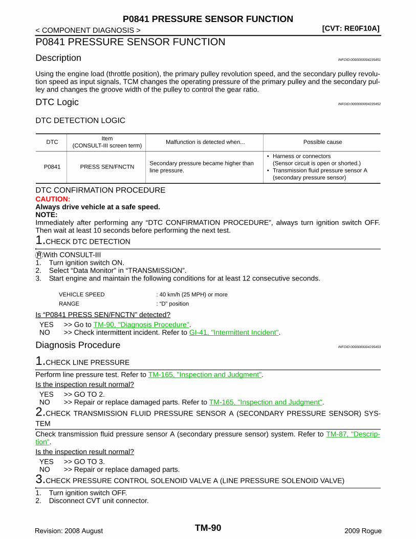
[CVT: RE0F10A]P0841 PRESSURE SENSOR FUNCTION
< COMPONENT DIAGNOSIS >
P0841 PRESSURE SENSOR FUNCTION
Description INFOID:0000000004235451
Using the engine load (throttle position), the primary pulley revolution speed, and the secondary pulley revolu-tion speed as input signals, TCM changes the operating pressure of the primary pulley and the secondary pul-ley and changes the groove width of the pulley to control the gear ratio.
DTC Logic INFOID:0000000004235452
DTC DETECTION LOGIC
DTC CONFIRMATION PROCEDURECAUTION:Always drive vehicle at a safe speed.NOTE:Immediately after performing any “DTC CONFIRMATION PROCEDURE”, always turn ignition switch OFF.Then wait at least 10 seconds before performing the next test.
1.CHECK DTC DETECTION
With CONSULT-III1. Turn ignition switch ON.2. Select “Data Monitor” in “TRANSMISSION”.3. Start engine and maintain the following conditions for at least 12 consecutive seconds.
Is “P0841 PRESS SEN/FNCTN” detected?YES >> Go to TM-90, "Diagnosis Procedure".NO >> Check intermittent incident. Refer to GI-41, "Intermittent Incident".
Diagnosis Procedure INFOID:0000000004235453
1.CHECK LINE PRESSURE
Perform line pressure test. Refer to TM-165, "Inspection and Judgment".Is the inspection result normal?YES >> GO TO 2.NO >> Repair or replace damaged parts. Refer to TM-165, "Inspection and Judgment".
2.CHECK TRANSMISSION FLUID PRESSURE SENSOR A (SECONDARY PRESSURE SENSOR) SYS-TEM
Check transmission fluid pressure sensor A (secondary pressure sensor) system. Refer to TM-87, "Descrip-tion".Is the inspection result normal?YES >> GO TO 3.NO >> Repair or replace damaged parts.
3.CHECK PRESSURE CONTROL SOLENOID VALVE A (LINE PRESSURE SOLENOID VALVE)
1. Turn ignition switch OFF.2. Disconnect CVT unit connector.
DTCItem
(CONSULT-III screen term)Malfunction is detected when... Possible cause
P0841 PRESS SEN/FNCTNSecondary pressure became higher than line pressure.
• Harness or connectors(Sensor circuit is open or shorted.)
• Transmission fluid pressure sensor A (secondary pressure sensor)
VEHICLE SPEED : 40 km/h (25 MPH) or more
RANGE : “D” position
TM-90Revision: 2008 August 2009 Rogue
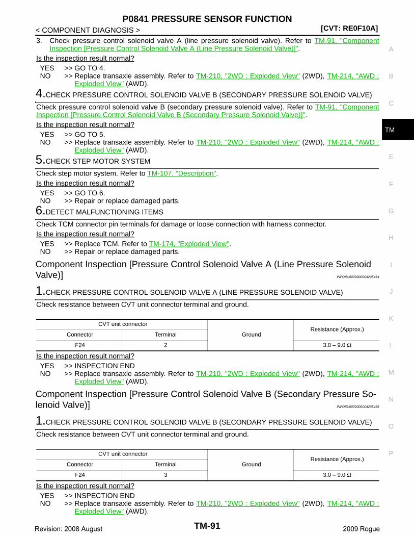
P0841 PRESSURE SENSOR FUNCTION[CVT: RE0F10A]
C
E
F
G
H
I
J
K
L
M
A
B
M
N
O
P
< COMPONENT DIAGNOSIS >
T
3. Check pressure control solenoid valve A (line pressure solenoid valve). Refer to TM-91, "ComponentInspection [Pressure Control Solenoid Valve A (Line Pressure Solenoid Valve)]".
Is the inspection result normal?YES >> GO TO 4.NO >> Replace transaxle assembly. Refer to TM-210, "2WD : Exploded View" (2WD), TM-214, "AWD :
Exploded View" (AWD).
4.CHECK PRESSURE CONTROL SOLENOID VALVE B (SECONDARY PRESSURE SOLENOID VALVE)
Check pressure control solenoid valve B (secondary pressure solenoid valve). Refer to TM-91, "ComponentInspection [Pressure Control Solenoid Valve B (Secondary Pressure Solenoid Valve)]".Is the inspection result normal?YES >> GO TO 5.NO >> Replace transaxle assembly. Refer to TM-210, "2WD : Exploded View" (2WD), TM-214, "AWD :
Exploded View" (AWD).
5.CHECK STEP MOTOR SYSTEM
Check step motor system. Refer to TM-107, "Description".Is the inspection result normal?YES >> GO TO 6.NO >> Repair or replace damaged parts.
6.DETECT MALFUNCTIONING ITEMS
Check TCM connector pin terminals for damage or loose connection with harness connector.Is the inspection result normal?YES >> Replace TCM. Refer to TM-174, "Exploded View".NO >> Repair or replace damaged parts.
Component Inspection [Pressure Control Solenoid Valve A (Line Pressure Solenoid Valve)] INFOID:0000000004235454
1.CHECK PRESSURE CONTROL SOLENOID VALVE A (LINE PRESSURE SOLENOID VALVE)
Check resistance between CVT unit connector terminal and ground.
Is the inspection result normal?YES >> INSPECTION ENDNO >> Replace transaxle assembly. Refer to TM-210, "2WD : Exploded View" (2WD), TM-214, "AWD :
Exploded View" (AWD).
Component Inspection [Pressure Control Solenoid Valve B (Secondary Pressure So-lenoid Valve)] INFOID:0000000004235455
1.CHECK PRESSURE CONTROL SOLENOID VALVE B (SECONDARY PRESSURE SOLENOID VALVE)
Check resistance between CVT unit connector terminal and ground.
Is the inspection result normal?YES >> INSPECTION ENDNO >> Replace transaxle assembly. Refer to TM-210, "2WD : Exploded View" (2WD), TM-214, "AWD :
Exploded View" (AWD).
CVT unit connector
GroundResistance (Approx.)
Connector Terminal
F24 2 3.0 – 9.0 Ω
CVT unit connector
GroundResistance (Approx.)
Connector Terminal
F24 3 3.0 – 9.0 Ω
TM-91Revision: 2008 August 2009 Rogue
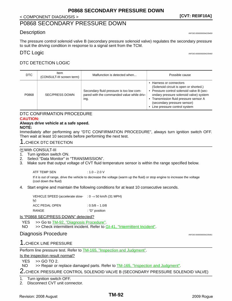
[CVT: RE0F10A]P0868 SECONDARY PRESSURE DOWN
< COMPONENT DIAGNOSIS >
P0868 SECONDARY PRESSURE DOWN
Description INFOID:0000000004235459
The pressure control solenoid valve B (secondary pressure solenoid valve) regulates the secondary pressureto suit the driving condition in response to a signal sent from the TCM.
DTC Logic INFOID:0000000004235460
DTC DETECTION LOGIC
DTC CONFIRMATION PROCEDURECAUTION:Always drive vehicle at a safe speed.NOTE:Immediately after performing any “DTC CONFIRMATION PROCEDURE”, always turn ignition switch OFF.Then wait at least 10 seconds before performing the next test.
1.CHECK DTC DETECTION
With CONSULT-III1. Turn ignition switch ON.2. Select “Data Monitor” in “TRANSMISSION”.3. Make sure that output voltage of CVT fluid temperature sensor is within the range specified below.
4. Start engine and maintain the following conditions for at least 10 consecutive seconds.
Is “P0868 SEC/PRESS DOWN” detected?YES >> Go to TM-92, "Diagnosis Procedure".NO >> Check intermittent incident. Refer to GI-41, "Intermittent Incident".
Diagnosis Procedure INFOID:0000000004235461
1.CHECK LINE PRESSURE
Perform line pressure test. Refer to TM-165, "Inspection and Judgment".Is the inspection result normal?YES >> GO TO 2.NO >> Repair or replace damaged parts. Refer to TM-165, "Inspection and Judgment".
2.CHECK PRESSURE CONTROL SOLENOID VALVE B (SECONDARY PRESSURE SOLENOID VALVE)
1. Turn ignition switch OFF.2. Disconnect CVT unit connector.
DTCItem
(CONSULT-III screen term)Malfunction is detected when... Possible cause
P0868 SEC/PRESS DOWNSecondary fluid pressure is too low com-pared with the commanded value while driv-ing.
• Harness or connectors(Solenoid circuit is open or shorted.)
• Pressure control solenoid valve B (sec-ondary pressure solenoid valve) system
• Transmission fluid pressure sensor A (secondary pressure sensor)
• Line pressure control system
ATF TEMP SEN : 1.0 – 2.0 V
If it is out of range, drive the vehicle to decrease the voltage (warm up the fluid) or stop engine to increase the voltage (cool down the fluid)
VEHICLE SPEED (accelerate slow-ly)
: 0 → 50 km/h (31 MPH)
ACC PEDAL OPEN : 0.5/8 – 1.0/8
RANGE : “D” position
TM-92Revision: 2008 August 2009 Rogue
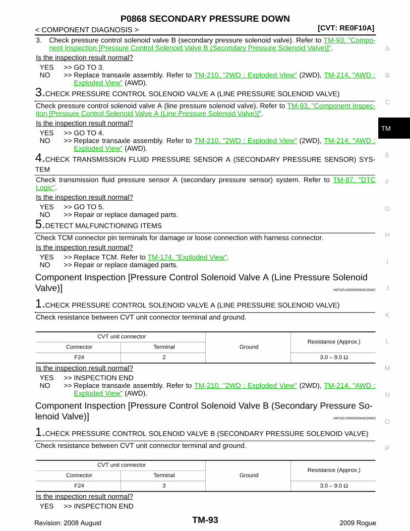
P0868 SECONDARY PRESSURE DOWN[CVT: RE0F10A]
C
E
F
G
H
I
J
K
L
M
A
B
M
N
O
P
< COMPONENT DIAGNOSIS >
T
3. Check pressure control solenoid valve B (secondary pressure solenoid valve). Refer to TM-93, "Compo-nent Inspection [Pressure Control Solenoid Valve B (Secondary Pressure Solenoid Valve)]".
Is the inspection result normal?YES >> GO TO 3.NO >> Replace transaxle assembly. Refer to TM-210, "2WD : Exploded View" (2WD), TM-214, "AWD :
Exploded View" (AWD).
3.CHECK PRESSURE CONTROL SOLENOID VALVE A (LINE PRESSURE SOLENOID VALVE)
Check pressure control solenoid valve A (line pressure solenoid valve). Refer to TM-93, "Component Inspec-tion [Pressure Control Solenoid Valve A (Line Pressure Solenoid Valve)]".Is the inspection result normal?YES >> GO TO 4.NO >> Replace transaxle assembly. Refer to TM-210, "2WD : Exploded View" (2WD), TM-214, "AWD :
Exploded View" (AWD).
4.CHECK TRANSMISSION FLUID PRESSURE SENSOR A (SECONDARY PRESSURE SENSOR) SYS-TEM
Check transmission fluid pressure sensor A (secondary pressure sensor) system. Refer to TM-87, "DTCLogic".Is the inspection result normal?YES >> GO TO 5.NO >> Repair or replace damaged parts.
5.DETECT MALFUNCTIONING ITEMS
Check TCM connector pin terminals for damage or loose connection with harness connector.Is the inspection result normal?YES >> Replace TCM. Refer to TM-174, "Exploded View".NO >> Repair or replace damaged parts.
Component Inspection [Pressure Control Solenoid Valve A (Line Pressure Solenoid Valve)] INFOID:0000000004235462
1.CHECK PRESSURE CONTROL SOLENOID VALVE A (LINE PRESSURE SOLENOID VALVE)
Check resistance between CVT unit connector terminal and ground.
Is the inspection result normal?YES >> INSPECTION ENDNO >> Replace transaxle assembly. Refer to TM-210, "2WD : Exploded View" (2WD), TM-214, "AWD :
Exploded View" (AWD).
Component Inspection [Pressure Control Solenoid Valve B (Secondary Pressure So-lenoid Valve)] INFOID:0000000004235463
1.CHECK PRESSURE CONTROL SOLENOID VALVE B (SECONDARY PRESSURE SOLENOID VALVE)
Check resistance between CVT unit connector terminal and ground.
Is the inspection result normal?YES >> INSPECTION END
CVT unit connector
GroundResistance (Approx.)
Connector Terminal
F24 2 3.0 – 9.0 Ω
CVT unit connector
GroundResistance (Approx.)
Connector Terminal
F24 3 3.0 – 9.0 Ω
TM-93Revision: 2008 August 2009 Rogue
[CVT: RE0F10A]P0868 SECONDARY PRESSURE DOWN
< COMPONENT DIAGNOSIS >NO >> Replace transaxle assembly. Refer to TM-210, "2WD : Exploded View" (2WD), TM-214, "AWD :
Exploded View" (AWD).
TM-94Revision: 2008 August 2009 Rogue
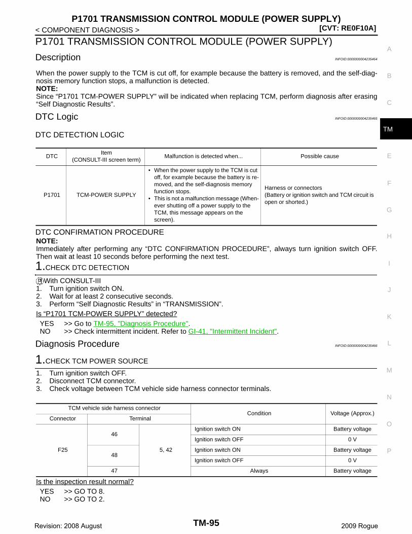
P1701 TRANSMISSION CONTROL MODULE (POWER SUPPLY)[CVT: RE0F10A]
C
E
F
G
H
I
J
K
L
M
A
B
M
N
O
P
< COMPONENT DIAGNOSIS >
T
P1701 TRANSMISSION CONTROL MODULE (POWER SUPPLY)
Description INFOID:0000000004235464
When the power supply to the TCM is cut off, for example because the battery is removed, and the self-diag-nosis memory function stops, a malfunction is detected.NOTE:Since “P1701 TCM-POWER SUPPLY” will be indicated when replacing TCM, perform diagnosis after erasing“Self Diagnostic Results”.
DTC Logic INFOID:0000000004235465
DTC DETECTION LOGIC
DTC CONFIRMATION PROCEDURENOTE:Immediately after performing any “DTC CONFIRMATION PROCEDURE”, always turn ignition switch OFF.Then wait at least 10 seconds before performing the next test.
1.CHECK DTC DETECTION
With CONSULT-III1. Turn ignition switch ON.2. Wait for at least 2 consecutive seconds.3. Perform “Self Diagnostic Results” in “TRANSMISSION”.Is “P1701 TCM-POWER SUPPLY” detected?YES >> Go to TM-95, "Diagnosis Procedure".NO >> Check intermittent incident. Refer to GI-41, "Intermittent Incident".
Diagnosis Procedure INFOID:0000000004235466
1.CHECK TCM POWER SOURCE
1. Turn ignition switch OFF.2. Disconnect TCM connector.3. Check voltage between TCM vehicle side harness connector terminals.
Is the inspection result normal?YES >> GO TO 8.NO >> GO TO 2.
DTCItem
(CONSULT-III screen term)Malfunction is detected when... Possible cause
P1701 TCM-POWER SUPPLY
• When the power supply to the TCM is cut off, for example because the battery is re-moved, and the self-diagnosis memory function stops.
• This is not a malfunction message (When-ever shutting off a power supply to the TCM, this message appears on the screen).
Harness or connectors(Battery or ignition switch and TCM circuit is open or shorted.)
TCM vehicle side harness connectorCondition Voltage (Approx.)
Connector Terminal
F25
46
5, 42
Ignition switch ON Battery voltage
Ignition switch OFF 0 V
48Ignition switch ON Battery voltage
Ignition switch OFF 0 V
47 Always Battery voltage
TM-95Revision: 2008 August 2009 Rogue

[CVT: RE0F10A]P1701 TRANSMISSION CONTROL MODULE (POWER SUPPLY)
< COMPONENT DIAGNOSIS >
2.CHECK TCM GROUND CIRCUIT
1. Turn ignition switch OFF.2. Check continuity between TCM vehicle side harness connector terminals and ground.
Is the inspection result normal?YES >> GO TO 3.NO >> Repair or replace damaged parts.
3.CHECK TCM POWER CIRCUIT
Check voltage between TCM vehicle side harness connector terminals and ground.
Is the inspection result normal?YES >> GO TO 8.NO-1 (Battery voltage is not supplied between terminals 46, 48 and ground)>>GO TO 4.NO-2 (Battery voltage is not supplied between terminal 47 and ground)>>GO TO 6.
4.CHECK HARNESS BETWEEN TCM AND IPDM E/R (STEP 1)
1. Turn ignition switch OFF.2. Disconnect IPDM E/R connector.3. Check continuity between TCM vehicle side harness connector terminals and IPDM E/R vehicle side har-
ness connector terminal.
Is the inspection result normal?YES >> GO TO 5.NO >> Repair or replace damaged parts.
5.CHECK HARNESS BETWEEN TCM AND IPDM E/R (STEP 2)
Check continuity between TCM vehicle side harness connector terminals and ground.
Is the inspection result normal?YES >> Check the following.
• Harness for short or open between ignition switch and IPDM E/R.
TCM vehicle side harness connector
Ground
ContinuityConnector Terminal
F255
Existed42
TCM vehicle side harness connector
Ground
Condition Voltage (Approx.)Connector Terminal
F25
46Ignition switch ON Battery voltage
Ignition switch OFF 0 V
48Ignition switch ON Battery voltage
Ignition switch OFF 0 V
47 Always Battery voltage
TCM vehicle side harness connector IPDM E/R vehicle side harness connectorContinuity
Connector Terminal Connector Terminal
F2546
E15 58 Existed48
TCM vehicle side harness connector
Ground
ContinuityConnector Terminal
F2546
Not existed48
TM-96Revision: 2008 August 2009 Rogue
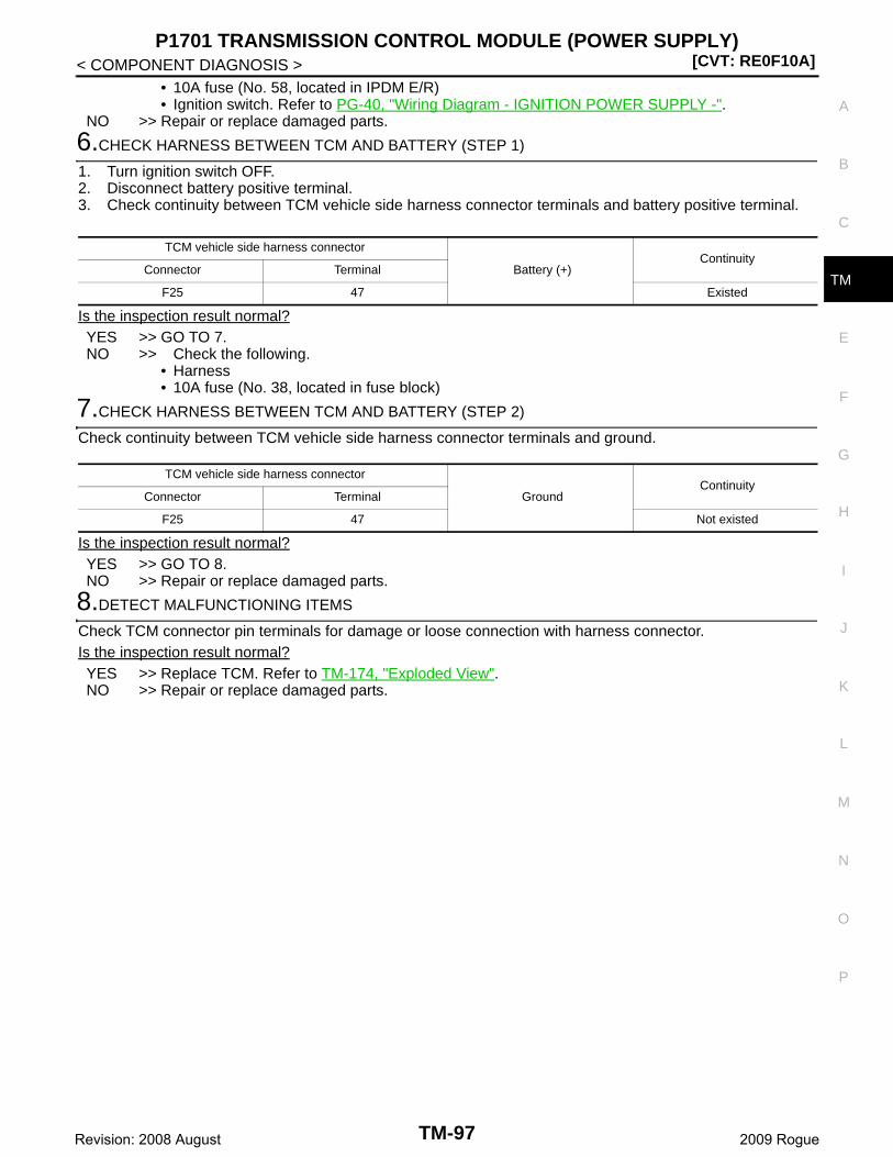
P1701 TRANSMISSION CONTROL MODULE (POWER SUPPLY)[CVT: RE0F10A]
C
E
F
G
H
I
J
K
L
M
A
B
M
N
O
P
< COMPONENT DIAGNOSIS >
T
• 10A fuse (No. 58, located in IPDM E/R)• Ignition switch. Refer to PG-40, "Wiring Diagram - IGNITION POWER SUPPLY -".
NO >> Repair or replace damaged parts.
6.CHECK HARNESS BETWEEN TCM AND BATTERY (STEP 1)
1. Turn ignition switch OFF.2. Disconnect battery positive terminal.3. Check continuity between TCM vehicle side harness connector terminals and battery positive terminal.
Is the inspection result normal?YES >> GO TO 7.NO >> Check the following.
• Harness• 10A fuse (No. 38, located in fuse block)
7.CHECK HARNESS BETWEEN TCM AND BATTERY (STEP 2)
Check continuity between TCM vehicle side harness connector terminals and ground.
Is the inspection result normal?YES >> GO TO 8.NO >> Repair or replace damaged parts.
8.DETECT MALFUNCTIONING ITEMS
Check TCM connector pin terminals for damage or loose connection with harness connector.Is the inspection result normal?YES >> Replace TCM. Refer to TM-174, "Exploded View".NO >> Repair or replace damaged parts.
TCM vehicle side harness connector
Battery (+)Continuity
Connector Terminal
F25 47 Existed
TCM vehicle side harness connector
GroundContinuity
Connector Terminal
F25 47 Not existed
TM-97Revision: 2008 August 2009 Rogue
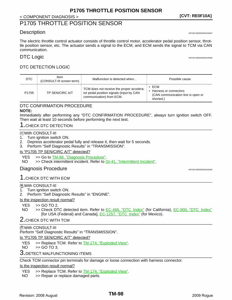
[CVT: RE0F10A]P1705 THROTTLE POSITION SENSOR
< COMPONENT DIAGNOSIS >
P1705 THROTTLE POSITION SENSOR
Description INFOID:0000000004235467
The electric throttle control actuator consists of throttle control motor, accelerator pedal position sensor, throt-tle position sensor, etc. The actuator sends a signal to the ECM, and ECM sends the signal to TCM via CANcommunication.
DTC Logic INFOID:0000000004235468
DTC DETECTION LOGIC
DTC CONFIRMATION PROCEDURENOTE:Immediately after performing any “DTC CONFIRMATION PROCEDURE”, always turn ignition switch OFF.Then wait at least 10 seconds before performing the next test.
1.CHECK DTC DETECTION
With CONSULT-III1. Turn ignition switch ON.2. Depress accelerator pedal fully and release it, then wait for 5 seconds.3. Perform “Self Diagnostic Results” in “TRANSMISSION”.Is “P1705 TP SEN/CIRC A/T” detected?YES >> Go to TM-98, "Diagnosis Procedure".NO >> Check intermittent incident. Refer to GI-41, "Intermittent Incident".
Diagnosis Procedure INFOID:0000000004235469
1.CHECK DTC WITH ECM
With CONSULT-III1. Turn ignition switch ON.2. Perform “Self Diagnostic Results” in “ENGINE”.Is the inspection result normal?YES >> GO TO 2.NO >> Check DTC detected item. Refer to EC-466, "DTC Index" (for California), EC-900, "DTC Index"
[for USA (Federal) and Canada], EC-1257, "DTC Index" (for Mexico).
2.CHECK DTC WITH TCM
With CONSULT-IIIPerform “Self Diagnostic Results” in “TRANSMISSION”.Is “P1705 TP SEN/CIRC A/T” detected?YES >> Replace TCM. Refer to TM-174, "Exploded View".NO >> GO TO 3.
3.DETECT MALFUNCTIONING ITEMS
Check TCM connector pin terminals for damage or loose connection with harness connector.Is the inspection result normal?YES >> Replace TCM. Refer to TM-174, "Exploded View".NO >> Repair or replace damaged parts.
DTCItem
(CONSULT-III screen term)Malfunction is detected when... Possible cause
P1705 TP SEN/CIRC A/TTCM does not receive the proper accelera-tor pedal position signals (input by CAN communication) from ECM.
• ECM• Harness or connectors
(CAN communication line is open or shorted.)
TM-98Revision: 2008 August 2009 Rogue

P1722 ESTM VEHICLE SPEED SIGNAL[CVT: RE0F10A]
C
E
F
G
H
I
J
K
L
M
A
B
M
N
O
P
< COMPONENT DIAGNOSIS >
T
P1722 ESTM VEHICLE SPEED SIGNAL
Description INFOID:0000000004235470
The vehicle speed signal is transmitted from ABS actuator and electric unit (control unit) to TCM via CAN com-munication line.
DTC Logic INFOID:0000000004235471
DTC DETECTION LOGIC
DTC CONFIRMATION PROCEDURECAUTION:Always drive vehicle at a safe speed.NOTE:Immediately after performing any “DTC CONFIRMATION PROCEDURE”, always turn ignition switch OFF.Then wait at least 10 seconds before performing the next test.
1.CHECK DTC DETECTION
With CONSULT-III1. Turn ignition switch ON.2. Select “Data Monitor” in “TRANSMISSION”.3. Start engine and maintain the following conditions for at least 5 consecutive seconds.
Is “P1722 ESTM VEH SPD SIG” detected?YES >> Go to TM-99, "Diagnosis Procedure".NO >> Check intermittent incident. Refer to GI-41, "Intermittent Incident".
Diagnosis Procedure INFOID:0000000004235472
1.CHECK DTC WITH ABS ACTUATOR AND ELECTRIC UNIT (CONTROL UNIT)
With CONSULT-IIIPerform “Self Diagnostic Results” in “ABS”.Is the inspection result normal?YES >> GO TO 2.NO >> Check DTC detected item. Refer to BRC-55, "DTC Index".
2.CHECK DTC WITH TCM
With CONSULT-IIIPerform “Self Diagnostic Results” in “TRANSMISSION”.Is “P1722 ESTM VEH SPD SIG” detected?YES >> Replace TCM. Refer to TM-174, "Exploded View".NO >> GO TO 3.
3.DETECT MALFUNCTIONING ITEMS
Check TCM connector pin terminals for damage or loose connection with harness connector.
DTCItem
(CONSULT-III screen term)Malfunction is detected when... Possible cause
P1722 ESTM VEH SPD SIG
• CAN communication with the ABS actua-tor and the electric unit (control unit) is malfunctioning.
• There is a big difference between the ve-hicle speed signal from the ABS actuator and the electric unit (control unit), and the vehicle speed sensor signal.
• Harness or connectors(Sensor circuit is open or shorted.)
• ABS actuator and electric unit (control unit)
ACC PEDAL OPEN : 1.0/8 or less
VEHICLE SPEED : 30 km/h (19 MPH) or more
TM-99Revision: 2008 August 2009 Rogue
[CVT: RE0F10A]P1722 ESTM VEHICLE SPEED SIGNAL
< COMPONENT DIAGNOSIS >Is the inspection result normal?YES >> Replace TCM. Refer to TM-174, "Exploded View".NO >> Repair or replace damaged parts.
TM-100Revision: 2008 August 2009 Rogue
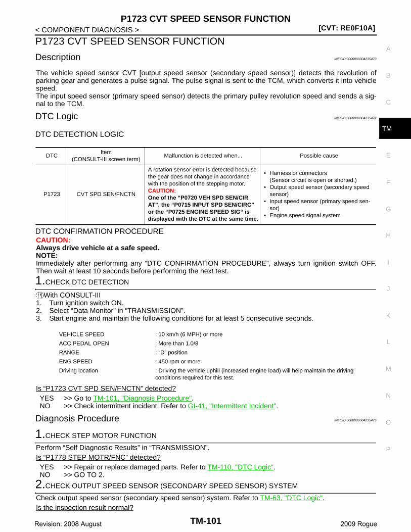
P1723 CVT SPEED SENSOR FUNCTION[CVT: RE0F10A]
C
E
F
G
H
I
J
K
L
M
A
B
M
N
O
P
< COMPONENT DIAGNOSIS >
T
P1723 CVT SPEED SENSOR FUNCTION
Description INFOID:0000000004235473
The vehicle speed sensor CVT [output speed sensor (secondary speed sensor)] detects the revolution ofparking gear and generates a pulse signal. The pulse signal is sent to the TCM, which converts it into vehiclespeed.The input speed sensor (primary speed sensor) detects the primary pulley revolution speed and sends a sig-nal to the TCM.
DTC Logic INFOID:0000000004235474
DTC DETECTION LOGIC
DTC CONFIRMATION PROCEDURECAUTION:Always drive vehicle at a safe speed.NOTE:Immediately after performing any “DTC CONFIRMATION PROCEDURE”, always turn ignition switch OFF.Then wait at least 10 seconds before performing the next test.
1.CHECK DTC DETECTION
With CONSULT-III1. Turn ignition switch ON.2. Select “Data Monitor” in “TRANSMISSION”.3. Start engine and maintain the following conditions for at least 5 consecutive seconds.
Is “P1723 CVT SPD SEN/FNCTN” detected?YES >> Go to TM-101, "Diagnosis Procedure".NO >> Check intermittent incident. Refer to GI-41, "Intermittent Incident".
Diagnosis Procedure INFOID:0000000004235475
1.CHECK STEP MOTOR FUNCTION
Perform “Self Diagnostic Results” in “TRANSMISSION”.Is “P1778 STEP MOTR/FNC” detected?YES >> Repair or replace damaged parts. Refer to TM-110, "DTC Logic".NO >> GO TO 2.
2.CHECK OUTPUT SPEED SENSOR (SECONDARY SPEED SENSOR) SYSTEM
Check output speed sensor (secondary speed sensor) system. Refer to TM-63, "DTC Logic".Is the inspection result normal?
DTCItem
(CONSULT-III screen term)Malfunction is detected when... Possible cause
P1723 CVT SPD SEN/FNCTN
A rotation sensor error is detected because the gear does not change in accordance with the position of the stepping motor.CAUTION:One of the “P0720 VEH SPD SEN/CIR AT”, the “P0715 INPUT SPD SEN/CIRC” or the “P0725 ENGINE SPEED SIG“ is displayed with the DTC at the same time.
• Harness or connectors(Sensor circuit is open or shorted.)
• Output speed sensor (secondary speed sensor)
• Input speed sensor (primary speed sen-sor)
• Engine speed signal system
VEHICLE SPEED : 10 km/h (6 MPH) or more
ACC PEDAL OPEN : More than 1.0/8
RANGE : “D” position
ENG SPEED : 450 rpm or more
Driving location : Driving the vehicle uphill (increased engine load) will help maintain the driving conditions required for this test.
TM-101Revision: 2008 August 2009 Rogue
[CVT: RE0F10A]P1723 CVT SPEED SENSOR FUNCTION
< COMPONENT DIAGNOSIS >YES >> GO TO 3.NO >> Repair or replace damaged parts.
3.CHECK INPUT SPEED SENSOR (PRIMARY SPEED SENSOR) SYSTEM
Check input speed sensor (primary speed sensor) system. Refer to TM-59, "DTC Logic".Is the inspection result normal?YES >> GO TO 4.NO >> Repair or replace damaged parts.
4.CHECK ENGINE SPEED SIGNAL SYSTEM
Check engine speed signal system. Refer to TM-67, "DTC Logic".Is the inspection result normal?YES >> GO TO 5.NO >> Repair or replace damaged parts.
5.DETECT MALFUNCTIONING ITEMS
Check TCM connector pin terminals for damage or loose connection with harness connector.Is the inspection result normal?YES >> Replace TCM. Refer to TM-174, "Exploded View".NO >> Repair or replace damaged parts.
TM-102Revision: 2008 August 2009 Rogue
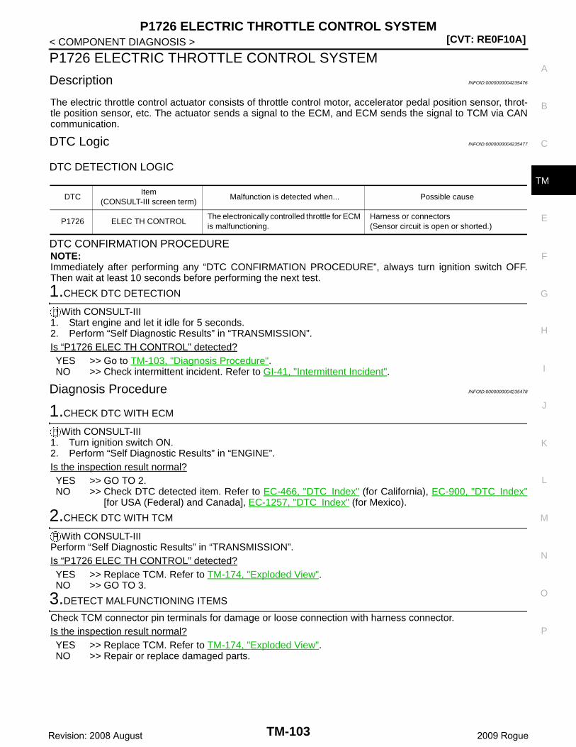
P1726 ELECTRIC THROTTLE CONTROL SYSTEM[CVT: RE0F10A]
C
E
F
G
H
I
J
K
L
M
A
B
M
N
O
P
< COMPONENT DIAGNOSIS >
T
P1726 ELECTRIC THROTTLE CONTROL SYSTEM
Description INFOID:0000000004235476
The electric throttle control actuator consists of throttle control motor, accelerator pedal position sensor, throt-tle position sensor, etc. The actuator sends a signal to the ECM, and ECM sends the signal to TCM via CANcommunication.
DTC Logic INFOID:0000000004235477
DTC DETECTION LOGIC
DTC CONFIRMATION PROCEDURENOTE:Immediately after performing any “DTC CONFIRMATION PROCEDURE”, always turn ignition switch OFF.Then wait at least 10 seconds before performing the next test.
1.CHECK DTC DETECTION
With CONSULT-III1. Start engine and let it idle for 5 seconds.2. Perform “Self Diagnostic Results” in “TRANSMISSION”.Is “P1726 ELEC TH CONTROL” detected?YES >> Go to TM-103, "Diagnosis Procedure".NO >> Check intermittent incident. Refer to GI-41, "Intermittent Incident".
Diagnosis Procedure INFOID:0000000004235478
1.CHECK DTC WITH ECM
With CONSULT-III1. Turn ignition switch ON.2. Perform “Self Diagnostic Results” in “ENGINE”.Is the inspection result normal?YES >> GO TO 2.NO >> Check DTC detected item. Refer to EC-466, "DTC Index" (for California), EC-900, "DTC Index"
[for USA (Federal) and Canada], EC-1257, "DTC Index" (for Mexico).
2.CHECK DTC WITH TCM
With CONSULT-IIIPerform “Self Diagnostic Results” in “TRANSMISSION”.Is “P1726 ELEC TH CONTROL” detected?YES >> Replace TCM. Refer to TM-174, "Exploded View".NO >> GO TO 3.
3.DETECT MALFUNCTIONING ITEMS
Check TCM connector pin terminals for damage or loose connection with harness connector.Is the inspection result normal?YES >> Replace TCM. Refer to TM-174, "Exploded View".NO >> Repair or replace damaged parts.
DTCItem
(CONSULT-III screen term)Malfunction is detected when... Possible cause
P1726 ELEC TH CONTROLThe electronically controlled throttle for ECM is malfunctioning.
Harness or connectors(Sensor circuit is open or shorted.)
TM-103Revision: 2008 August 2009 Rogue
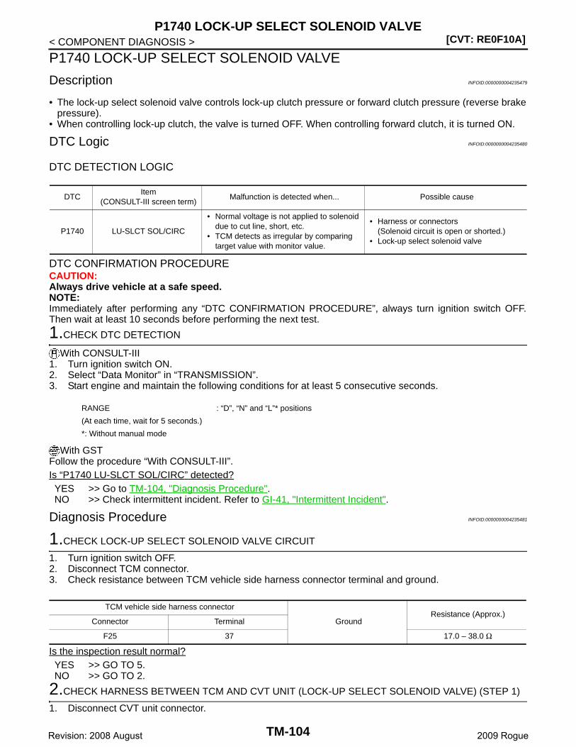
[CVT: RE0F10A]P1740 LOCK-UP SELECT SOLENOID VALVE
< COMPONENT DIAGNOSIS >
P1740 LOCK-UP SELECT SOLENOID VALVE
Description INFOID:0000000004235479
• The lock-up select solenoid valve controls lock-up clutch pressure or forward clutch pressure (reverse brakepressure).
• When controlling lock-up clutch, the valve is turned OFF. When controlling forward clutch, it is turned ON.
DTC Logic INFOID:0000000004235480
DTC DETECTION LOGIC
DTC CONFIRMATION PROCEDURECAUTION:Always drive vehicle at a safe speed.NOTE:Immediately after performing any “DTC CONFIRMATION PROCEDURE”, always turn ignition switch OFF.Then wait at least 10 seconds before performing the next test.
1.CHECK DTC DETECTION
With CONSULT-III1. Turn ignition switch ON.2. Select “Data Monitor” in “TRANSMISSION”.3. Start engine and maintain the following conditions for at least 5 consecutive seconds.
With GSTFollow the procedure “With CONSULT-III”.Is “P1740 LU-SLCT SOL/CIRC” detected?YES >> Go to TM-104, "Diagnosis Procedure".NO >> Check intermittent incident. Refer to GI-41, "Intermittent Incident".
Diagnosis Procedure INFOID:0000000004235481
1.CHECK LOCK-UP SELECT SOLENOID VALVE CIRCUIT
1. Turn ignition switch OFF.2. Disconnect TCM connector.3. Check resistance between TCM vehicle side harness connector terminal and ground.
Is the inspection result normal?YES >> GO TO 5.NO >> GO TO 2.
2.CHECK HARNESS BETWEEN TCM AND CVT UNIT (LOCK-UP SELECT SOLENOID VALVE) (STEP 1)
1. Disconnect CVT unit connector.
DTCItem
(CONSULT-III screen term)Malfunction is detected when... Possible cause
P1740 LU-SLCT SOL/CIRC
• Normal voltage is not applied to solenoid due to cut line, short, etc.
• TCM detects as irregular by comparing target value with monitor value.
• Harness or connectors(Solenoid circuit is open or shorted.)
• Lock-up select solenoid valve
RANGE : “D”, “N” and “L”* positions
(At each time, wait for 5 seconds.)
*: Without manual mode
TCM vehicle side harness connector
GroundResistance (Approx.)
Connector Terminal
F25 37 17.0 – 38.0 Ω
TM-104Revision: 2008 August 2009 Rogue
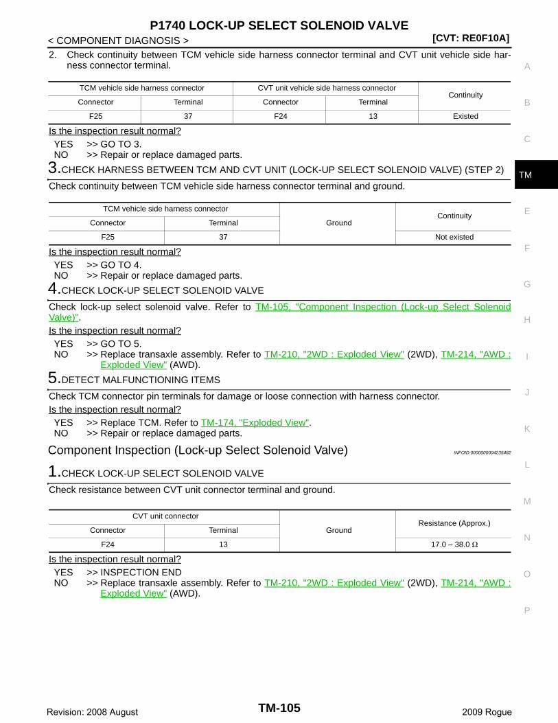
P1740 LOCK-UP SELECT SOLENOID VALVE[CVT: RE0F10A]
C
E
F
G
H
I
J
K
L
M
A
B
M
N
O
P
< COMPONENT DIAGNOSIS >
T
2. Check continuity between TCM vehicle side harness connector terminal and CVT unit vehicle side har-ness connector terminal.
Is the inspection result normal?YES >> GO TO 3.NO >> Repair or replace damaged parts.
3.CHECK HARNESS BETWEEN TCM AND CVT UNIT (LOCK-UP SELECT SOLENOID VALVE) (STEP 2)
Check continuity between TCM vehicle side harness connector terminal and ground.
Is the inspection result normal?YES >> GO TO 4.NO >> Repair or replace damaged parts.
4.CHECK LOCK-UP SELECT SOLENOID VALVE
Check lock-up select solenoid valve. Refer to TM-105, "Component Inspection (Lock-up Select SolenoidValve)".Is the inspection result normal?YES >> GO TO 5.NO >> Replace transaxle assembly. Refer to TM-210, "2WD : Exploded View" (2WD), TM-214, "AWD :
Exploded View" (AWD).
5.DETECT MALFUNCTIONING ITEMS
Check TCM connector pin terminals for damage or loose connection with harness connector.Is the inspection result normal?YES >> Replace TCM. Refer to TM-174, "Exploded View".NO >> Repair or replace damaged parts.
Component Inspection (Lock-up Select Solenoid Valve) INFOID:0000000004235482
1.CHECK LOCK-UP SELECT SOLENOID VALVE
Check resistance between CVT unit connector terminal and ground.
Is the inspection result normal?YES >> INSPECTION ENDNO >> Replace transaxle assembly. Refer to TM-210, "2WD : Exploded View" (2WD), TM-214, "AWD :
Exploded View" (AWD).
TCM vehicle side harness connector CVT unit vehicle side harness connectorContinuity
Connector Terminal Connector Terminal
F25 37 F24 13 Existed
TCM vehicle side harness connector
GroundContinuity
Connector Terminal
F25 37 Not existed
CVT unit connector
GroundResistance (Approx.)
Connector Terminal
F24 13 17.0 – 38.0 Ω
TM-105Revision: 2008 August 2009 Rogue
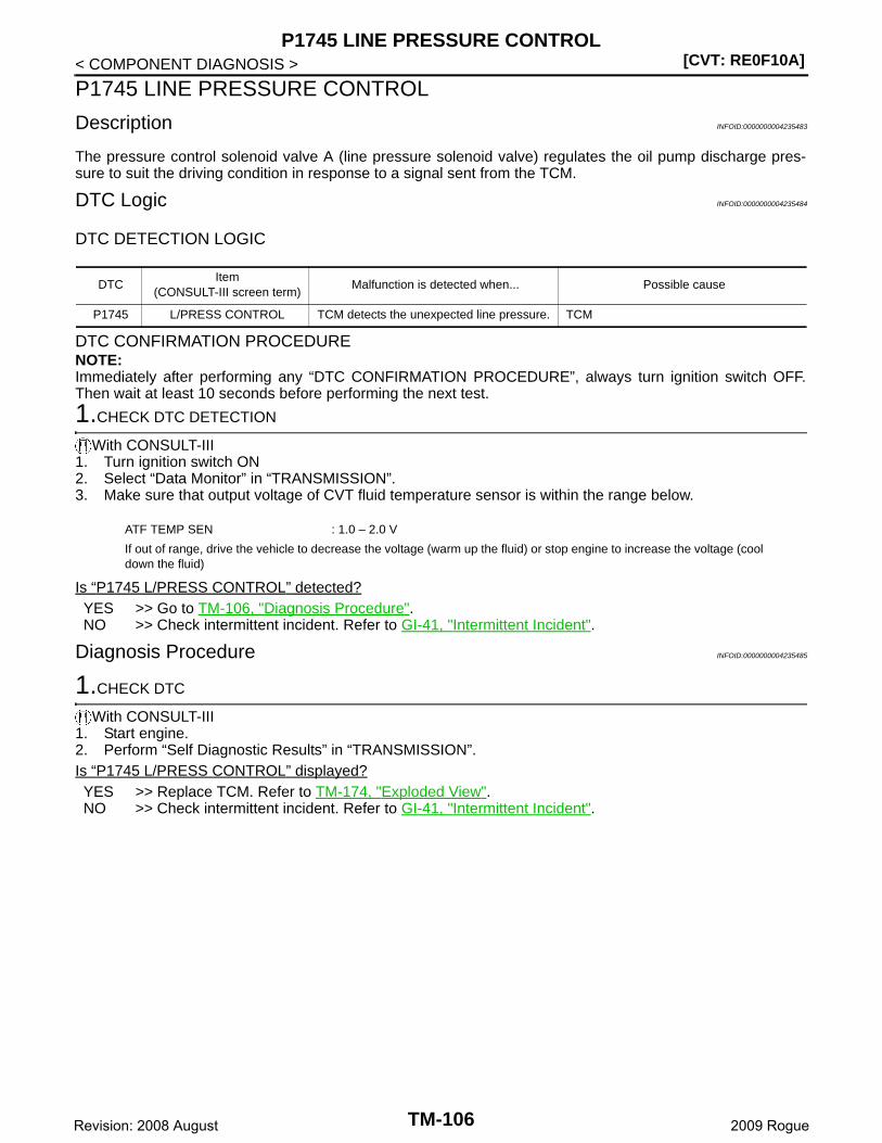
[CVT: RE0F10A]P1745 LINE PRESSURE CONTROL
< COMPONENT DIAGNOSIS >
P1745 LINE PRESSURE CONTROL
Description INFOID:0000000004235483
The pressure control solenoid valve A (line pressure solenoid valve) regulates the oil pump discharge pres-sure to suit the driving condition in response to a signal sent from the TCM.
DTC Logic INFOID:0000000004235484
DTC DETECTION LOGIC
DTC CONFIRMATION PROCEDURENOTE:Immediately after performing any “DTC CONFIRMATION PROCEDURE”, always turn ignition switch OFF.Then wait at least 10 seconds before performing the next test.
1.CHECK DTC DETECTION
With CONSULT-III1. Turn ignition switch ON2. Select “Data Monitor” in “TRANSMISSION”.3. Make sure that output voltage of CVT fluid temperature sensor is within the range below.
Is “P1745 L/PRESS CONTROL” detected?YES >> Go to TM-106, "Diagnosis Procedure".NO >> Check intermittent incident. Refer to GI-41, "Intermittent Incident".
Diagnosis Procedure INFOID:0000000004235485
1.CHECK DTC
With CONSULT-III1. Start engine.2. Perform “Self Diagnostic Results” in “TRANSMISSION”.Is “P1745 L/PRESS CONTROL” displayed?YES >> Replace TCM. Refer to TM-174, "Exploded View".NO >> Check intermittent incident. Refer to GI-41, "Intermittent Incident".
DTCItem
(CONSULT-III screen term)Malfunction is detected when... Possible cause
P1745 L/PRESS CONTROL TCM detects the unexpected line pressure. TCM
ATF TEMP SEN : 1.0 – 2.0 V
If out of range, drive the vehicle to decrease the voltage (warm up the fluid) or stop engine to increase the voltage (cool down the fluid)
TM-106Revision: 2008 August 2009 Rogue
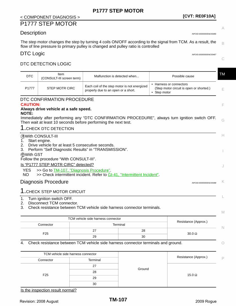
P1777 STEP MOTOR[CVT: RE0F10A]
C
E
F
G
H
I
J
K
L
M
A
B
M
N
O
P
< COMPONENT DIAGNOSIS >
T
P1777 STEP MOTOR
Description INFOID:0000000004235486
The step motor changes the step by turning 4 coils ON/OFF according to the signal from TCM. As a result, theflow of line pressure to primary pulley is changed and pulley ratio is controlled
DTC Logic INFOID:0000000004235487
DTC DETECTION LOGIC
DTC CONFIRMATION PROCEDURECAUTION:Always drive vehicle at a safe speed.NOTE:Immediately after performing any “DTC CONFIRMATION PROCEDURE”, always turn ignition switch OFF.Then wait at least 10 seconds before performing the next test.
1.CHECK DTC DETECTION
With CONSULT-III1. Start engine.2. Drive vehicle for at least 5 consecutive seconds.3. Perform “Self Diagnostic Results” in “TRANSMISSION”.
With GSTFollow the procedure “With CONSULT-III”.Is “P1777 STEP MOTR CIRC” detected?YES >> Go to TM-107, "Diagnosis Procedure".NO >> Check intermittent incident. Refer to GI-41, "Intermittent Incident".
Diagnosis Procedure INFOID:0000000004235488
1.CHECK STEP MOTOR CIRCUIT
1. Turn ignition switch OFF.2. Disconnect TCM connector.3. Check resistance between TCM vehicle side harness connector terminals.
4. Check resistance between TCM vehicle side harness connector terminals and ground.
Is the inspection result normal?
DTCItem
(CONSULT-III screen term)Malfunction is detected when... Possible cause
P1777 STEP MOTR CIRCEach coil of the step motor is not energized properly due to an open or a short.
• Harness or connectors(Step motor circuit is open or shorted.)
• Step motor
TCM vehicle side harness connectorResistance (Approx.)
Connector Terminal
F2527 28
30.0 Ω29 30
TCM vehicle side harness connector
Ground
Resistance (Approx.)Connector Terminal
F25
27
15.0 Ω28
29
30
TM-107Revision: 2008 August 2009 Rogue
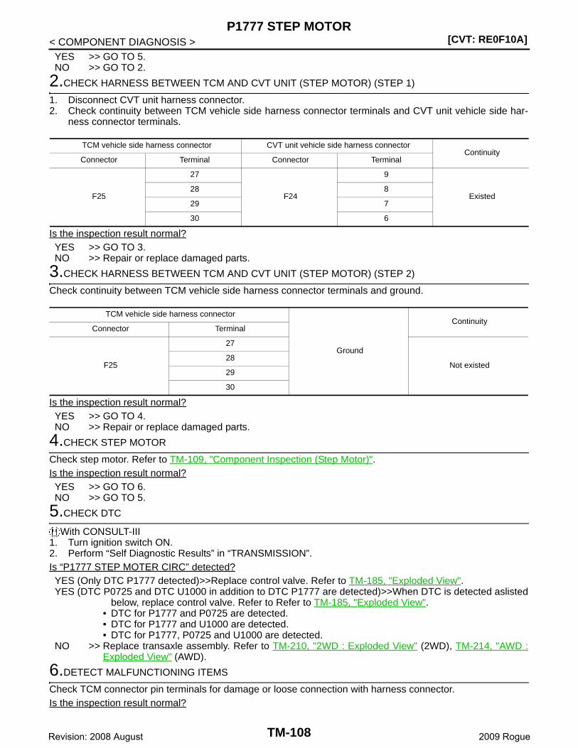
[CVT: RE0F10A]P1777 STEP MOTOR
< COMPONENT DIAGNOSIS >YES >> GO TO 5.NO >> GO TO 2.
2.CHECK HARNESS BETWEEN TCM AND CVT UNIT (STEP MOTOR) (STEP 1)
1. Disconnect CVT unit harness connector.2. Check continuity between TCM vehicle side harness connector terminals and CVT unit vehicle side har-
ness connector terminals.
Is the inspection result normal?YES >> GO TO 3.NO >> Repair or replace damaged parts.
3.CHECK HARNESS BETWEEN TCM AND CVT UNIT (STEP MOTOR) (STEP 2)
Check continuity between TCM vehicle side harness connector terminals and ground.
Is the inspection result normal?YES >> GO TO 4.NO >> Repair or replace damaged parts.
4.CHECK STEP MOTOR
Check step motor. Refer to TM-109, "Component Inspection (Step Motor)".Is the inspection result normal?YES >> GO TO 6.NO >> GO TO 5.
5.CHECK DTC
With CONSULT-III1. Turn ignition switch ON.2. Perform “Self Diagnostic Results” in “TRANSMISSION”.Is “P1777 STEP MOTER CIRC” detected?YES (Only DTC P1777 detected)>>Replace control valve. Refer to TM-185, "Exploded View".YES (DTC P0725 and DTC U1000 in addition to DTC P1777 are detected)>>When DTC is detected aslisted
below, replace control valve. Refer to Refer to TM-185, "Exploded View".• DTC for P1777 and P0725 are detected.• DTC for P1777 and U1000 are detected.• DTC for P1777, P0725 and U1000 are detected.
NO >> Replace transaxle assembly. Refer to TM-210, "2WD : Exploded View" (2WD), TM-214, "AWD :Exploded View" (AWD).
6.DETECT MALFUNCTIONING ITEMS
Check TCM connector pin terminals for damage or loose connection with harness connector.Is the inspection result normal?
TCM vehicle side harness connector CVT unit vehicle side harness connectorContinuity
Connector Terminal Connector Terminal
F25
27
F24
9
Existed28 8
29 7
30 6
TCM vehicle side harness connector
Ground
ContinuityConnector Terminal
F25
27
Not existed28
29
30
TM-108Revision: 2008 August 2009 Rogue
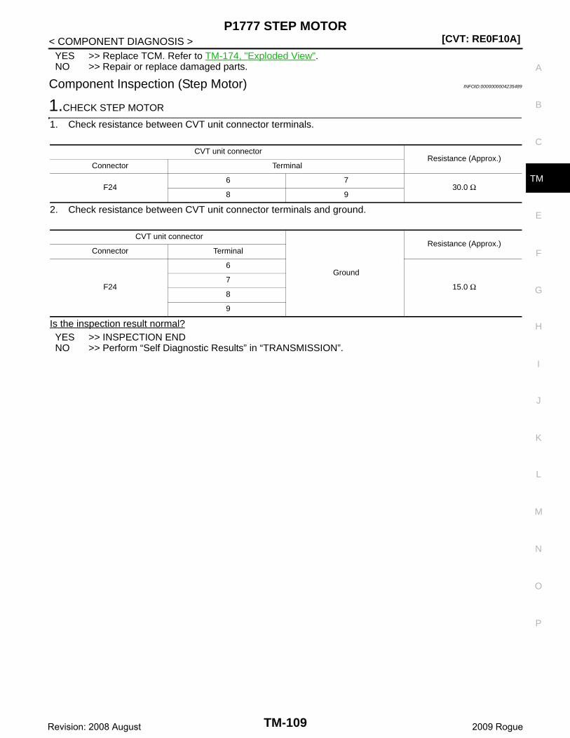
P1777 STEP MOTOR[CVT: RE0F10A]
C
E
F
G
H
I
J
K
L
M
A
B
M
N
O
P
< COMPONENT DIAGNOSIS >
T
YES >> Replace TCM. Refer to TM-174, "Exploded View".NO >> Repair or replace damaged parts.
Component Inspection (Step Motor) INFOID:0000000004235489
1.CHECK STEP MOTOR
1. Check resistance between CVT unit connector terminals.
2. Check resistance between CVT unit connector terminals and ground.
Is the inspection result normal?YES >> INSPECTION ENDNO >> Perform “Self Diagnostic Results” in “TRANSMISSION”.
CVT unit connectorResistance (Approx.)
Connector Terminal
F246 7
30.0 Ω8 9
CVT unit connector
Ground
Resistance (Approx.)Connector Terminal
F24
6
15.0 Ω7
8
9
TM-109Revision: 2008 August 2009 Rogue
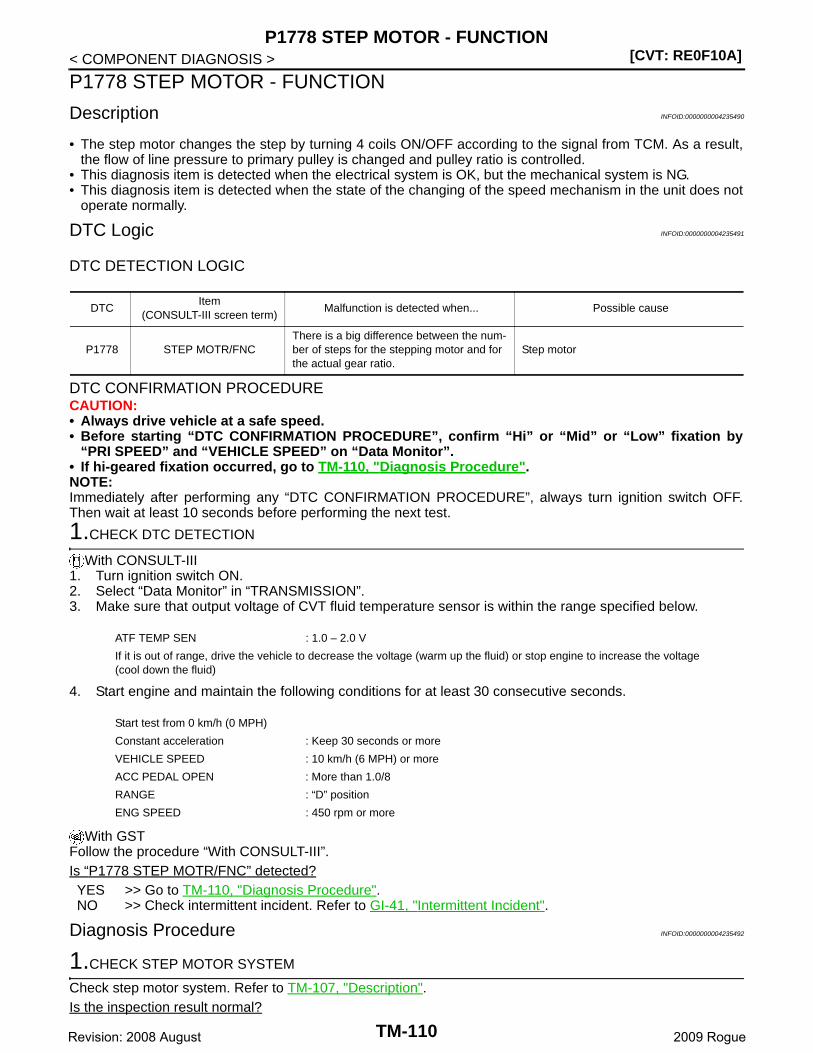
[CVT: RE0F10A]P1778 STEP MOTOR - FUNCTION
< COMPONENT DIAGNOSIS >
P1778 STEP MOTOR - FUNCTION
Description INFOID:0000000004235490
• The step motor changes the step by turning 4 coils ON/OFF according to the signal from TCM. As a result,the flow of line pressure to primary pulley is changed and pulley ratio is controlled.
• This diagnosis item is detected when the electrical system is OK, but the mechanical system is NG.• This diagnosis item is detected when the state of the changing of the speed mechanism in the unit does not
operate normally.
DTC Logic INFOID:0000000004235491
DTC DETECTION LOGIC
DTC CONFIRMATION PROCEDURECAUTION:• Always drive vehicle at a safe speed.• Before starting “DTC CONFIRMATION PROCEDURE”, confirm “Hi” or “Mid” or “Low” fixation by
“PRI SPEED” and “VEHICLE SPEED” on “Data Monitor”.• If hi-geared fixation occurred, go to TM-110, "Diagnosis Procedure".NOTE:Immediately after performing any “DTC CONFIRMATION PROCEDURE”, always turn ignition switch OFF.Then wait at least 10 seconds before performing the next test.
1.CHECK DTC DETECTION
With CONSULT-III1. Turn ignition switch ON.2. Select “Data Monitor” in “TRANSMISSION”.3. Make sure that output voltage of CVT fluid temperature sensor is within the range specified below.
4. Start engine and maintain the following conditions for at least 30 consecutive seconds.
With GSTFollow the procedure “With CONSULT-III”.Is “P1778 STEP MOTR/FNC” detected?YES >> Go to TM-110, "Diagnosis Procedure".NO >> Check intermittent incident. Refer to GI-41, "Intermittent Incident".
Diagnosis Procedure INFOID:0000000004235492
1.CHECK STEP MOTOR SYSTEM
Check step motor system. Refer to TM-107, "Description".Is the inspection result normal?
DTCItem
(CONSULT-III screen term)Malfunction is detected when... Possible cause
P1778 STEP MOTR/FNCThere is a big difference between the num-ber of steps for the stepping motor and for the actual gear ratio.
Step motor
ATF TEMP SEN : 1.0 – 2.0 V
If it is out of range, drive the vehicle to decrease the voltage (warm up the fluid) or stop engine to increase the voltage (cool down the fluid)
Start test from 0 km/h (0 MPH)
Constant acceleration : Keep 30 seconds or more
VEHICLE SPEED : 10 km/h (6 MPH) or more
ACC PEDAL OPEN : More than 1.0/8
RANGE : “D” position
ENG SPEED : 450 rpm or more
TM-110Revision: 2008 August 2009 Rogue
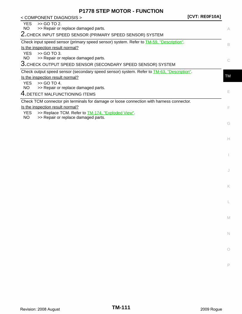
P1778 STEP MOTOR - FUNCTION[CVT: RE0F10A]
C
E
F
G
H
I
J
K
L
M
A
B
M
N
O
P
< COMPONENT DIAGNOSIS >
T
YES >> GO TO 2.NO >> Repair or replace damaged parts.
2.CHECK INPUT SPEED SENSOR (PRIMARY SPEED SENSOR) SYSTEM
Check input speed sensor (primary speed sensor) system. Refer to TM-59, "Description".Is the inspection result normal?YES >> GO TO 3.NO >> Repair or replace damaged parts.
3.CHECK OUTPUT SPEED SENSOR (SECONDARY SPEED SENSOR) SYSTEM
Check output speed sensor (secondary speed sensor) system. Refer to TM-63, "Description".Is the inspection result normal?YES >> GO TO 4.NO >> Repair or replace damaged parts.
4.DETECT MALFUNCTIONING ITEMS
Check TCM connector pin terminals for damage or loose connection with harness connector.Is the inspection result normal?YES >> Replace TCM. Refer to TM-174, "Exploded View".NO >> Repair or replace damaged parts.
TM-111Revision: 2008 August 2009 Rogue
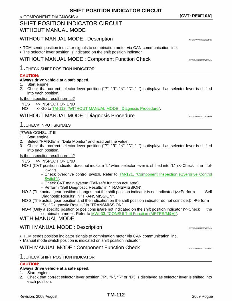
[CVT: RE0F10A]SHIFT POSITION INDICATOR CIRCUIT
< COMPONENT DIAGNOSIS >
SHIFT POSITION INDICATOR CIRCUITWITHOUT MANUAL MODE
WITHOUT MANUAL MODE : Description INFOID:0000000004235493
• TCM sends position indicator signals to combination meter via CAN communication line.• The selector lever position is indicated on the shift position indicator.
WITHOUT MANUAL MODE : Component Function Check INFOID:0000000004235494
1.CHECK SHIFT POSITION INDICATOR
CAUTION:Always drive vehicle at a safe speed.1. Start engine.2. Check that correct selector lever position (“P”, “R”, “N”, “D”, “L”) is displayed as selector lever is shifted
into each position.Is the inspection result normal?YES >> INSPECTION ENDNO >> Go to TM-112, "WITHOUT MANUAL MODE : Diagnosis Procedure".
WITHOUT MANUAL MODE : Diagnosis Procedure INFOID:0000000004235495
1.CHECK INPUT SIGNALS
With CONSULT-III1. Start engine.2. Select “RANGE” in “Data Monitor” and read out the value.3. Check that correct selector lever position (“P”, “R”, “N”, “D”, “L”) is displayed as selector lever is shifted
into each position.Is the inspection result normal?YES >> INSPECTION ENDNO-1 (CVT position indicator does not indicate “L” when selector lever is shifted into “L”.)>>Check the fol-
lowing.• Check overdrive control switch. Refer to TM-121, "Component Inspection (Overdrive Control
Switch)".• Check CVT main system (Fail-safe function actuated).- Perform “Self Diagnostic Results” in “TRANSMISSION”.
NO-2 (The actual gear position changes, but the shift position indicator is not indicated.)>>Perform “SelfDiagnostic Results” in “TRANSMISSION”.
NO-3 (The actual gear position and the indication on the shift position indicator do not coincide.)>>Perform“Self Diagnostic Results” in “TRANSMISSION”.
NO-4 (Only a specific position or positions is/are not indicated on the shift position indicator.)>>Check thecombination meter. Refer to MWI-33, "CONSULT-III Function (METER/M&A)".
WITH MANUAL MODE
WITH MANUAL MODE : Description INFOID:0000000004235496
• TCM sends position indicator signals to combination meter via CAN communication line.• Manual mode switch position is indicated on shift position indicator.
WITH MANUAL MODE : Component Function Check INFOID:0000000004235497
1.CHECK SHIFT POSITION INDICATOR
CAUTION:Always drive vehicle at a safe speed.1. Start engine.2. Check that correct selector lever position (“P”, “N”, “R” or “D”) is displayed as selector lever is shifted into
each position.
TM-112Revision: 2008 August 2009 Rogue
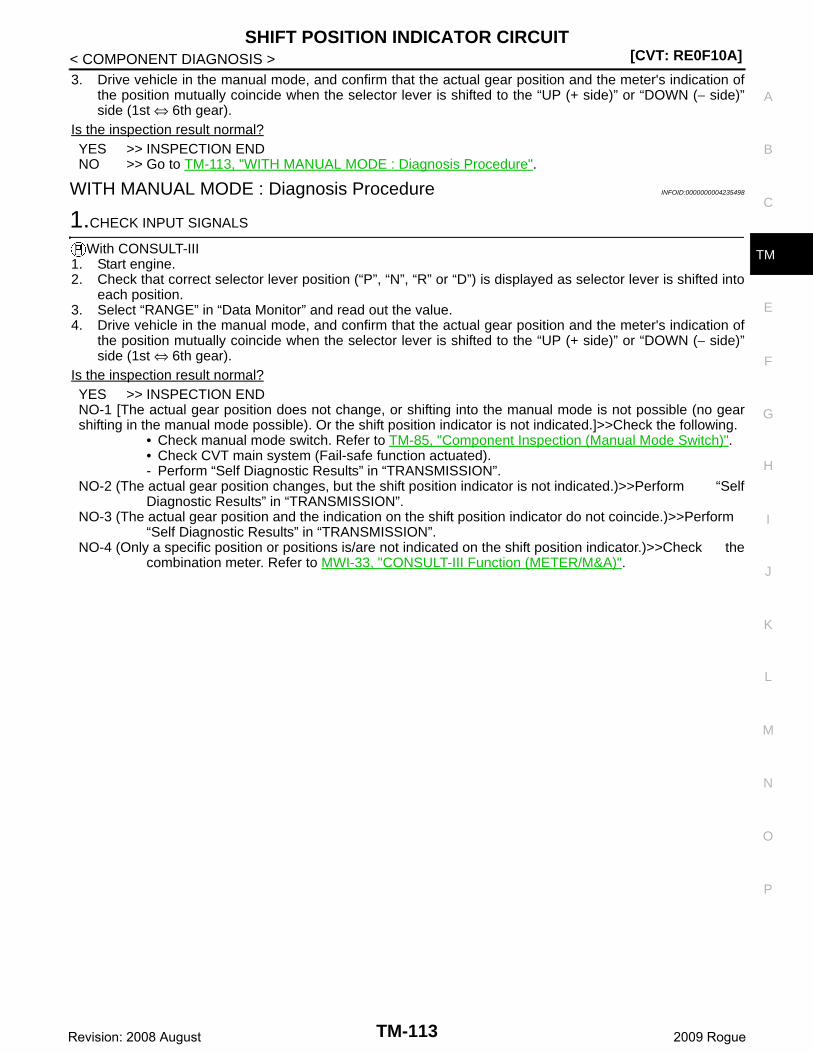
SHIFT POSITION INDICATOR CIRCUIT[CVT: RE0F10A]
C
E
F
G
H
I
J
K
L
M
A
B
M
N
O
P
< COMPONENT DIAGNOSIS >
T
3. Drive vehicle in the manual mode, and confirm that the actual gear position and the meter's indication ofthe position mutually coincide when the selector lever is shifted to the “UP (+ side)” or “DOWN (− side)”side (1st ⇔ 6th gear).
Is the inspection result normal?YES >> INSPECTION ENDNO >> Go to TM-113, "WITH MANUAL MODE : Diagnosis Procedure".
WITH MANUAL MODE : Diagnosis Procedure INFOID:0000000004235498
1.CHECK INPUT SIGNALS
With CONSULT-III1. Start engine.2. Check that correct selector lever position (“P”, “N”, “R” or “D”) is displayed as selector lever is shifted into
each position.3. Select “RANGE” in “Data Monitor” and read out the value.4. Drive vehicle in the manual mode, and confirm that the actual gear position and the meter's indication of
the position mutually coincide when the selector lever is shifted to the “UP (+ side)” or “DOWN (− side)”side (1st ⇔ 6th gear).
Is the inspection result normal?YES >> INSPECTION ENDNO-1 [The actual gear position does not change, or shifting into the manual mode is not possible (no gearshifting in the manual mode possible). Or the shift position indicator is not indicated.]>>Check the following.
• Check manual mode switch. Refer to TM-85, "Component Inspection (Manual Mode Switch)".• Check CVT main system (Fail-safe function actuated).- Perform “Self Diagnostic Results” in “TRANSMISSION”.
NO-2 (The actual gear position changes, but the shift position indicator is not indicated.)>>Perform “SelfDiagnostic Results” in “TRANSMISSION”.
NO-3 (The actual gear position and the indication on the shift position indicator do not coincide.)>>Perform“Self Diagnostic Results” in “TRANSMISSION”.
NO-4 (Only a specific position or positions is/are not indicated on the shift position indicator.)>>Check thecombination meter. Refer to MWI-33, "CONSULT-III Function (METER/M&A)".
TM-113Revision: 2008 August 2009 Rogue
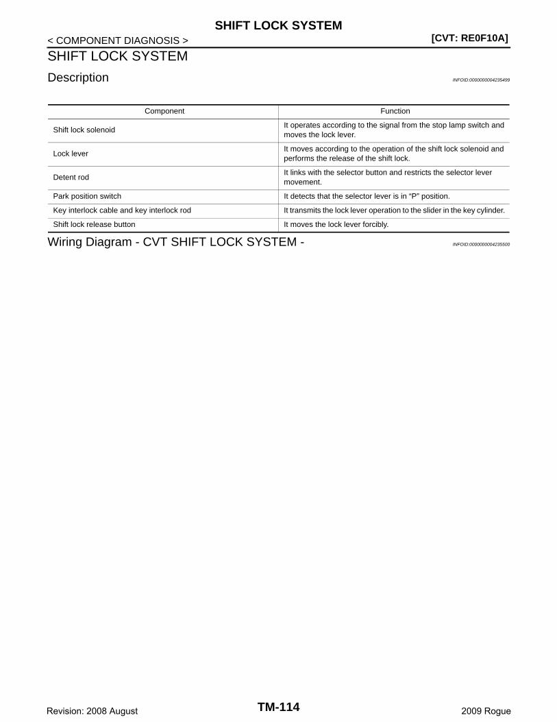
[CVT: RE0F10A]SHIFT LOCK SYSTEM
< COMPONENT DIAGNOSIS >
SHIFT LOCK SYSTEM
Description INFOID:0000000004235499
Wiring Diagram - CVT SHIFT LOCK SYSTEM - INFOID:0000000004235500
Component Function
Shift lock solenoidIt operates according to the signal from the stop lamp switch and moves the lock lever.
Lock leverIt moves according to the operation of the shift lock solenoid and performs the release of the shift lock.
Detent rodIt links with the selector button and restricts the selector lever movement.
Park position switch It detects that the selector lever is in “P” position.
Key interlock cable and key interlock rod It transmits the lock lever operation to the slider in the key cylinder.
Shift lock release button It moves the lock lever forcibly.
TM-114Revision: 2008 August 2009 Rogue
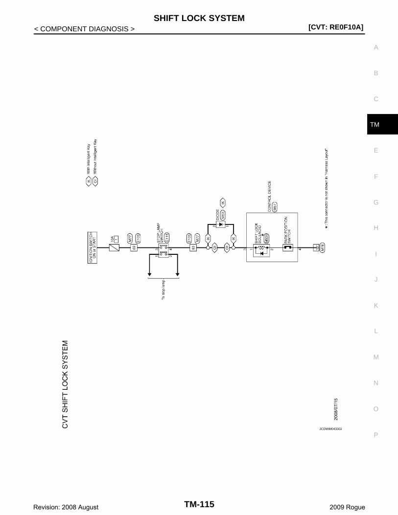
SHIFT LOCK SYSTEM[CVT: RE0F10A]
C
E
F
G
H
I
J
K
L
M
A
B
M
N
O
P
< COMPONENT DIAGNOSIS >
T
JCDWM0433GB
TM-115Revision: 2008 August 2009 Rogue
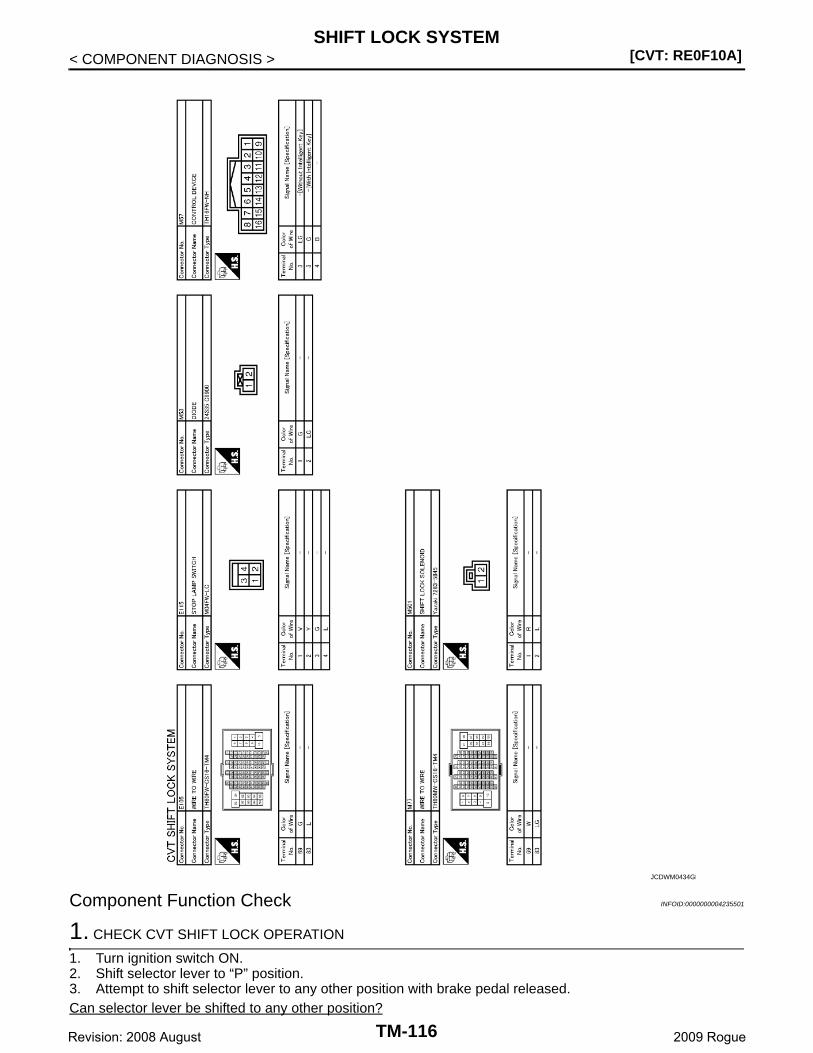
[CVT: RE0F10A]SHIFT LOCK SYSTEM
< COMPONENT DIAGNOSIS >
Component Function Check INFOID:0000000004235501
1. CHECK CVT SHIFT LOCK OPERATION
1. Turn ignition switch ON.2. Shift selector lever to “P” position.3. Attempt to shift selector lever to any other position with brake pedal released.Can selector lever be shifted to any other position?
JCDWM0434GB
TM-116Revision: 2008 August 2009 Rogue

SHIFT LOCK SYSTEM[CVT: RE0F10A]
C
E
F
G
H
I
J
K
L
M
A
B
M
N
O
P
< COMPONENT DIAGNOSIS >
T
YES >> INSPECTION ENDNO >> GO TO 2.
2. CHECK CVT SHIFT LOCK OPERATION
Attempt to shift selector lever to any other position with brake pedal depressed.Can the selector lever be shifted to any other position?YES >> INSPECTION ENDNO >> Go to TM-117, "Diagnosis Procedure".
Diagnosis Procedure INFOID:0000000004235502
1. CHECK POWER SOURCE
1. Turn ignition switch OFF.2. Disconnect stop lamp switch connector.3. Turn ignition switch ON.4. Check voltage between stop lamp switch vehicle side harness connector and ground.
Is the inspection result normal?YES >> GO TO 2. NO >> Check the following.
• Harness for short or open between ignition switch and stop lamp switch• 10A fuse (No. 1, located in fuse block)• Ignition switch
2.CHECK STOP LAMP SWITCH
1. Turn ignition switch OFF.2. Check stop lamp switch. Refer to TM-119, "Component Inspection (Stop Lamp Switch)".Is the inspection result normal?YES >> GO TO 3.NO >> Replace stop lamp switch. Refer to BR-18, "Exploded View".
3.CHECK HARNESS BETWEEN STOP LAMP SWITCH AND CONTROL DEVICE (PART 1)
1. Disconnect control device connector.2. Check continuity between stop lamp switch vehicle side harness connector terminal and control devices
vehicle side connector terminal.
Is the inspection result normal?YES >> GO TO 4.NO >> Repair or replace damaged parts.
4.CHECK HARNESS BETWEEN STOP LAMP SWITCH AND CONTROL DEVICE (PART 2)
Check continuity between stop lamp switch vehicle side harness connector terminal and ground.
Is the inspection result normal?YES >> GO TO 5.NO >> Repair or replace damaged parts.
Stop lamp switch vehicle side harness connector
GroundVoltage (Approx.)
Connector Terminal
E115 3 Battery voltage
Stop lamp switch vehicle side harness connector Control device vehicle side harness connectorContinuity
Connector Terminal Connector Terminal
E115 4 M57 3 Existed
Stop lamp switch vehicle side harness connector
GroundContinuity
Connector Terminal
E115 4 Not existed
TM-117Revision: 2008 August 2009 Rogue
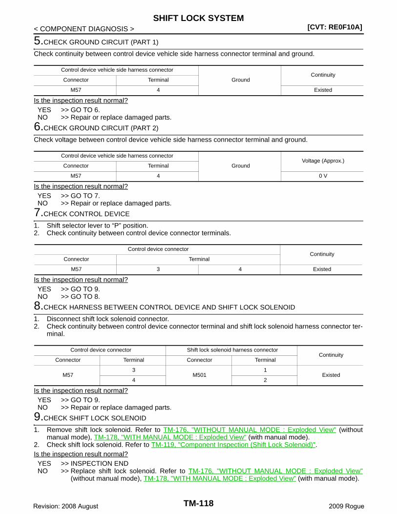
[CVT: RE0F10A]SHIFT LOCK SYSTEM
< COMPONENT DIAGNOSIS >
5.CHECK GROUND CIRCUIT (PART 1)
Check continuity between control device vehicle side harness connector terminal and ground.
Is the inspection result normal?YES >> GO TO 6.NO >> Repair or replace damaged parts.
6.CHECK GROUND CIRCUIT (PART 2)
Check voltage between control device vehicle side harness connector terminal and ground.
Is the inspection result normal?YES >> GO TO 7.NO >> Repair or replace damaged parts.
7.CHECK CONTROL DEVICE
1. Shift selector lever to “P” position.2. Check continuity between control device connector terminals.
Is the inspection result normal?YES >> GO TO 9.NO >> GO TO 8.
8.CHECK HARNESS BETWEEN CONTROL DEVICE AND SHIFT LOCK SOLENOID
1. Disconnect shift lock solenoid connector.2. Check continuity between control device connector terminal and shift lock solenoid harness connector ter-
minal.
Is the inspection result normal?YES >> GO TO 9.NO >> Repair or replace damaged parts.
9.CHECK SHIFT LOCK SOLENOID
1. Remove shift lock solenoid. Refer to TM-176, "WITHOUT MANUAL MODE : Exploded View" (withoutmanual mode), TM-178, "WITH MANUAL MODE : Exploded View" (with manual mode).
2. Check shift lock solenoid. Refer to TM-119, "Component Inspection (Shift Lock Solenoid)".Is the inspection result normal?YES >> INSPECTION ENDNO >> Replace shift lock solenoid. Refer to TM-176, "WITHOUT MANUAL MODE : Exploded View"
(without manual mode), TM-178, "WITH MANUAL MODE : Exploded View" (with manual mode).
Control device vehicle side harness connector
GroundContinuity
Connector Terminal
M57 4 Existed
Control device vehicle side harness connector
GroundVoltage (Approx.)
Connector Terminal
M57 4 0 V
Control device connectorContinuity
Connector Terminal
M57 3 4 Existed
Control device connector Shift lock solenoid harness connectorContinuity
Connector Terminal Connector Terminal
M573
M5011
Existed4 2
TM-118Revision: 2008 August 2009 Rogue
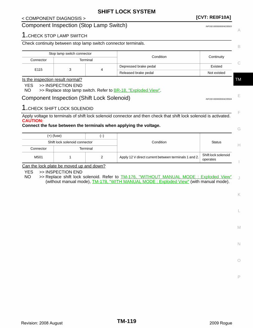
SHIFT LOCK SYSTEM[CVT: RE0F10A]
C
E
F
G
H
I
J
K
L
M
A
B
M
N
O
P
< COMPONENT DIAGNOSIS >
T
Component Inspection (Stop Lamp Switch) INFOID:0000000004235503
1.CHECK STOP LAMP SWITCH
Check continuity between stop lamp switch connector terminals.
Is the inspection result normal?YES >> INSPECTION ENDNO >> Replace stop lamp switch. Refer to BR-18, "Exploded View".
Component Inspection (Shift Lock Solenoid) INFOID:0000000004235504
1.CHECK SHIFT LOCK SOLENOID
Apply voltage to terminals of shift lock solenoid connector and then check that shift lock solenoid is activated.CAUTION:Connect the fuse between the terminals when applying the voltage.
Can the lock plate be moved up and down?YES >> INSPECTION ENDNO >> Replace shift lock solenoid. Refer to TM-176, "WITHOUT MANUAL MODE : Exploded View"
(without manual mode), TM-178, "WITH MANUAL MODE : Exploded View" (with manual mode).
Stop lamp switch connectorCondition Continuity
Connector Terminal
E115 3 4Depressed brake pedal Existed
Released brake pedal Not existed
(+) (fuse) (−)
Condition StatusShift lock solenoid connector
Connector Terminal
M501 1 2 Apply 12 V direct current between terminals 1 and 2.Shift lock solenoid operates
TM-119Revision: 2008 August 2009 Rogue
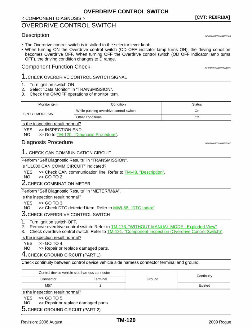
[CVT: RE0F10A]OVERDRIVE CONTROL SWITCH
< COMPONENT DIAGNOSIS >
OVERDRIVE CONTROL SWITCH
Description INFOID:0000000004235505
• The Overdrive control switch is installed to the selector lever knob.• When turning ON the Overdrive control switch (OD OFF indicator lamp turns ON), the driving condition
becomes Overdrive OFF. When turning OFF the Overdrive control switch (OD OFF indicator lamp turnsOFF), the driving condition changes to D range.
Component Function Check INFOID:0000000004235506
1.CHECK OVERDRIVE CONTROL SWITCH SIGNAL
1. Turn ignition switch ON.2. Select “Data Monitor” in “TRANSMISSION”.3. Check the ON/OFF operations of monitor item.
Is the inspection result normal?YES >> INSPECTION END.NO >> Go to TM-120, "Diagnosis Procedure".
Diagnosis Procedure INFOID:0000000004235507
1. CHECK CAN COMMUNICATION CIRCUIT
Perform “Self Diagnostic Results” in “TRANSMISSION”.Is “U1000 CAN COMM CIRCUIT” indicated?YES >> Check CAN communication line. Refer to TM-48, "Description".NO >> GO TO 2.
2.CHECK COMBINATION METER
Perform “Self Diagnostic Results” in “METER/M&A”.Is the inspection result normal?YES >> GO TO 3.NO >> Check DTC detected item. Refer to MWI-68, "DTC Index".
3.CHECK OVERDRIVE CONTROL SWITCH
1. Turn ignition switch OFF.2. Remove overdrive control switch. Refer to TM-176, "WITHOUT MANUAL MODE : Exploded View".3. Check overdrive control switch. Refer to TM-121, "Component Inspection (Overdrive Control Switch)".Is the inspection result normal?YES >> GO TO 4.NO >> Repair or replace damaged parts.
4.CHECK GROUND CIRCUIT (PART 1)
Check continuity between control device vehicle side harness connector terminal and ground.
Is the inspection result normal?YES >> GO TO 5.NO >> Repair or replace damaged parts.
5.CHECK GROUND CIRCUIT (PART 2)
Monitor item Condition Status
SPORT MODE SWWhile pushing overdrive control switch On
Other conditions Off
Control device vehicle side harness connector
GroundContinuity
Connector Terminal
M57 2 Existed
TM-120Revision: 2008 August 2009 Rogue
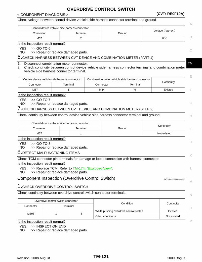
OVERDRIVE CONTROL SWITCH[CVT: RE0F10A]
C
E
F
G
H
I
J
K
L
M
A
B
M
N
O
P
< COMPONENT DIAGNOSIS >
T
Check voltage between control device vehicle side harness connector terminal and ground.
Is the inspection result normal?YES >> GO TO 6.NO >> Repair or replace damaged parts.
6.CHECK HARNESS BETWEEN CVT DEVICE AND COMBINATION METER (PART 1)
1. Disconnect combination meter connector.2. Check continuity between control device vehicle side harness connector terminal and combination meter
vehicle side harness connector terminal.
Is the inspection result normal?YES >> GO TO 7.NO >> Repair or replace damaged parts.
7.CHECK HARNESS BETWEEN CVT DEVICE AND COMBINATION METER (STEP 2)
Check continuity between control device vehicle side harness connector terminal and ground.
Is the inspection result normal?YES >> GO TO 8.NO >> Repair or replace damaged parts.
8.DETECT MALFUNCTIONING ITEMS
Check TCM connector pin terminals for damage or loose connection with harness connector.Is the inspection result normal?YES >> Replace TCM. Refer to TM-174, "Exploded View".NO >> Repair or replace damaged parts.
Component Inspection (Overdrive Control Switch) INFOID:0000000004235508
1.CHECK OVERDRIVE CONTROL SWITCH
Check continuity between overdrive control switch connector terminals.
Is the inspection result normal?YES >> INSPECTION ENDNO >> Repair or replace damaged parts.
Control device vehicle side harness connector
GroundVoltage (Approx.)
Connector Terminal
M57 2 0 V
Control device vehicle side harness connector Combination meter vehicle side harness connectorContinuity
Connector Terminal Connector Terminal
M57 1 M34 9 Existed
Control device vehicle side harness connector
GroundContinuity
Connector Terminal
M57 1 Not existed
Overdrive control switch connectorCondition Continuity
Connector Terminal
M503 1 3While pushing overdrive control switch Existed
Other conditions Not existed
TM-121Revision: 2008 August 2009 Rogue
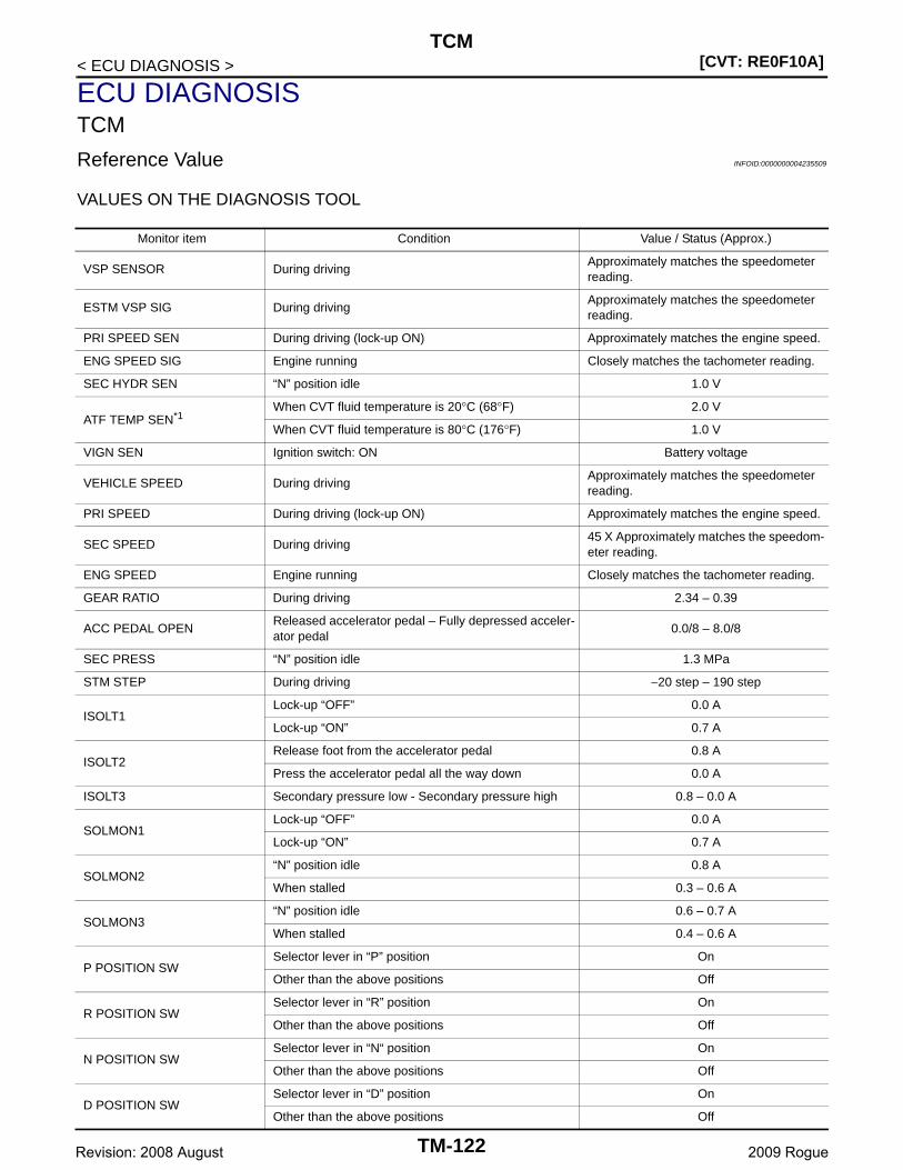
[CVT: RE0F10A]TCM
< ECU DIAGNOSIS >
ECU DIAGNOSISTCM
Reference Value INFOID:0000000004235509
VALUES ON THE DIAGNOSIS TOOL
Monitor item Condition Value / Status (Approx.)
VSP SENSOR During drivingApproximately matches the speedometer reading.
ESTM VSP SIG During drivingApproximately matches the speedometer reading.
PRI SPEED SEN During driving (lock-up ON) Approximately matches the engine speed.
ENG SPEED SIG Engine running Closely matches the tachometer reading.
SEC HYDR SEN “N” position idle 1.0 V
ATF TEMP SEN*1When CVT fluid temperature is 20°C (68°F) 2.0 V
When CVT fluid temperature is 80°C (176°F) 1.0 V
VIGN SEN Ignition switch: ON Battery voltage
VEHICLE SPEED During drivingApproximately matches the speedometer reading.
PRI SPEED During driving (lock-up ON) Approximately matches the engine speed.
SEC SPEED During driving45 X Approximately matches the speedom-eter reading.
ENG SPEED Engine running Closely matches the tachometer reading.
GEAR RATIO During driving 2.34 – 0.39
ACC PEDAL OPENReleased accelerator pedal – Fully depressed acceler-ator pedal
0.0/8 – 8.0/8
SEC PRESS “N” position idle 1.3 MPa
STM STEP During driving −20 step – 190 step
ISOLT1Lock-up “OFF” 0.0 A
Lock-up “ON” 0.7 A
ISOLT2Release foot from the accelerator pedal 0.8 A
Press the accelerator pedal all the way down 0.0 A
ISOLT3 Secondary pressure low - Secondary pressure high 0.8 – 0.0 A
SOLMON1Lock-up “OFF” 0.0 A
Lock-up “ON” 0.7 A
SOLMON2“N” position idle 0.8 A
When stalled 0.3 – 0.6 A
SOLMON3“N” position idle 0.6 – 0.7 A
When stalled 0.4 – 0.6 A
P POSITION SWSelector lever in “P” position On
Other than the above positions Off
R POSITION SWSelector lever in “R” position On
Other than the above positions Off
N POSITION SWSelector lever in “N“ position On
Other than the above positions Off
D POSITION SWSelector lever in “D” position On
Other than the above positions Off
TM-122Revision: 2008 August 2009 Rogue
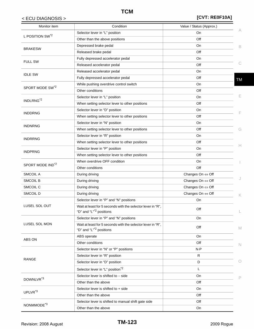
TCM[CVT: RE0F10A]
C
E
F
G
H
I
J
K
L
M
A
B
M
N
O
P
< ECU DIAGNOSIS >
T
L POSITION SW*2Selector lever in “L” position On
Other than the above positions Off
BRAKESWDepressed brake pedal On
Released brake pedal Off
FULL SWFully depressed accelerator pedal On
Released accelerator pedal Off
IDLE SWReleased accelerator pedal On
Fully depressed accelerator pedal Off
SPORT MODE SW*2While pushing overdrive control switch On
Other conditions Off
INDLRNG*2Selector lever in “L” position On
When setting selector lever to other positions Off
INDDRNGSelector lever in “D” position On
When setting selector lever to other positions Off
INDNRNGSelector lever in “N“ position On
When setting selector lever to other positions Off
INDRRNGSelector lever in “R” position On
When setting selector lever to other positions Off
INDPRNGSelector lever in “P” position On
When setting selector lever to other positions Off
SPORT MODE IND*2When overdrive OFF condition On
Other conditions Off
SMCOIL A During driving Changes On ⇔ Off
SMCOIL B During driving Changes On ⇔ Off
SMCOIL C During driving Changes On ⇔ Off
SMCOIL D During driving Changes On ⇔ Off
LUSEL SOL OUT
Selector lever in “P” and “N” positions On
Wait at least for 5 seconds with the selector lever in “R”,
“D” and “L”*2 positionsOff
LUSEL SOL MON
Selector lever in “P” and “N” positions On
Wait at least for 5 seconds with the selector lever in “R”,
“D” and “L”*2 positionsOff
ABS ONABS operate On
Other conditions Off
RANGE
Selector lever in “N” or “P” positions N·P
Selector lever in “R” position R
Selector lever in “D” position D
Selector lever in “L” position*2 L
DOWNLVR*3Selector lever is shifted to − side On
Other than the above Off
UPLVR*3Selector lever is shifted to + side On
Other than the above Off
NONMMODE*3Selector lever is shifted to manual shift gate side Off
Other than the above On
Monitor item Condition Value / Status (Approx.)
TM-123Revision: 2008 August 2009 Rogue
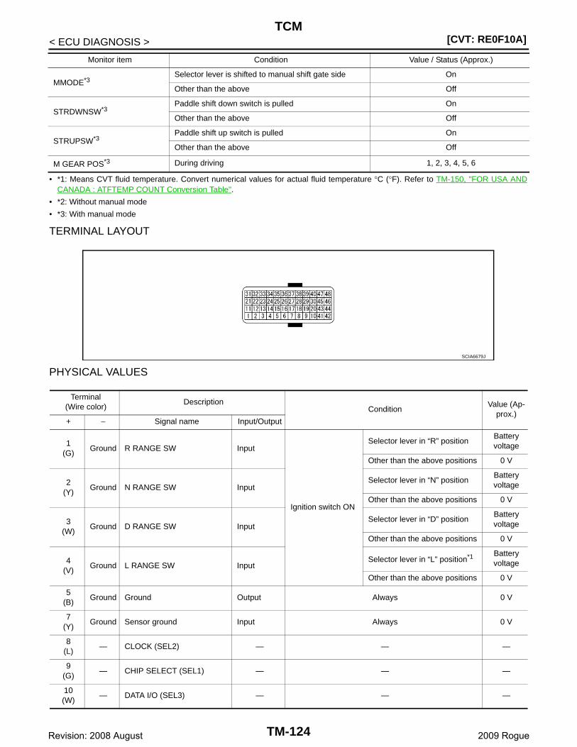
[CVT: RE0F10A]TCM
< ECU DIAGNOSIS >
• *1: Means CVT fluid temperature. Convert numerical values for actual fluid temperature °C (°F). Refer to TM-150, "FOR USA ANDCANADA : ATFTEMP COUNT Conversion Table".
• *2: Without manual mode
• *3: With manual mode
TERMINAL LAYOUT
PHYSICAL VALUES
MMODE*3Selector lever is shifted to manual shift gate side On
Other than the above Off
STRDWNSW*3Paddle shift down switch is pulled On
Other than the above Off
STRUPSW*3Paddle shift up switch is pulled On
Other than the above Off
M GEAR POS*3 During driving 1, 2, 3, 4, 5, 6
Monitor item Condition Value / Status (Approx.)
SCIA6679J
Terminal(Wire color)
DescriptionCondition
Value (Ap-prox.)
+ − Signal name Input/Output
1(G)
Ground R RANGE SW Input
Ignition switch ON
Selector lever in “R” positionBattery voltage
Other than the above positions 0 V
2(Y)
Ground N RANGE SW InputSelector lever in “N” position
Battery voltage
Other than the above positions 0 V
3(W)
Ground D RANGE SW InputSelector lever in “D” position
Battery voltage
Other than the above positions 0 V
4(V)
Ground L RANGE SW InputSelector lever in “L” position*1 Battery
voltage
Other than the above positions 0 V
5(B)
Ground Ground Output Always 0 V
7(Y)
Ground Sensor ground Input Always 0 V
8(L)
— CLOCK (SEL2) — — —
9(G)
— CHIP SELECT (SEL1) — — —
10(W)
— DATA I/O (SEL3) — — —
TM-124Revision: 2008 August 2009 Rogue
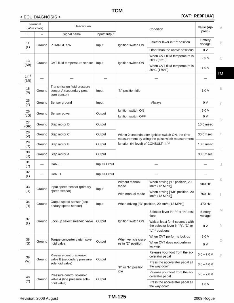
TCM[CVT: RE0F10A]
C
E
F
G
H
I
J
K
L
M
A
B
M
N
O
P
< ECU DIAGNOSIS >
T
11(L)
Ground P RANGE SW Input Ignition switch ONSelector lever in “P” position
Battery voltage
Other than the above positions 0 V
13(SB)
Ground CVT fluid temperature sensor Input Ignition switch ON
When CVT fluid temperature is 20°C (68°F)
2.0 V
When CVT fluid temperature is 80°C (176°F)
1.0 V
14*3
(BR)— — — — —
15(P)
GroundTransmission fluid pressure sensor A (secondary pres-sure sensor)
Input “N” position idle 1.0 V
25(Y)
Ground Sensor ground Input Always 0 V
26(LG)
Ground Sensor power OutputIgnition switch ON 5.0 V
Ignition switch OFF 0 V
27(GR)
Ground Step motor D Output
Within 2 seconds after ignition switch ON, the time measurement by using the pulse width measurement
function (Hi level) of CONSULT-III.*2
10.0 msec
28(V)
Ground Step motor C Output 30.0 msec
29(O)
Ground Step motor B Output 10.0 msec
30(R)
Ground Step motor A Output 30.0 msec
31(P)
— CAN-L Input/Output — —
32(L)
— CAN-H Input/Output — —
33(O)
GroundInput speed sensor (primary speed sensor)
Input
Without manual mode
When driving [“L” position, 20 km/h (12 MPH)]
900 Hz
With manual modeWhen driving [“M1” position, 20 km/h (12 MPH)]
760 Hz
34(R)
GroundOutput speed sensor (sec-ondary speed sensor)
Input When driving [“D” position, 20 km/h (12 MPH)] 470 Hz
37(L)
Ground Lock-up select solenoid valve Output Ignition switch ON
Selector lever in “P” or “N” posi-tions
Battery voltage
Wait at least for 5 seconds with the selector lever in “R”, “D” or
“L”*1 positions0 V
38(G)
GroundTorque converter clutch sole-noid valve
OutputWhen vehicle cruis-es in “D” position
When CVT performs lock-up 5.0 V
When CVT does not perform lock-up
0 V
39(W)
GroundPressure control solenoid valve B (secondary pressure solenoid valve)
Output
“P” or “N” position idle
Release your foot from the ac-celerator pedal
5.0 – 7.0 V
Press the accelerator pedal all the way down
3.0 – 4.0 V
40(Y)
GroundPressure control solenoid valve A (line pressure sole-noid valve)
Output
Release your foot from the ac-celerator pedal
5.0 – 7.0 V
Press the accelerator pedal all the way down
1.0 V
Terminal(Wire color)
DescriptionCondition
Value (Ap-prox.)
+ − Signal name Input/Output
TM-125Revision: 2008 August 2009 Rogue
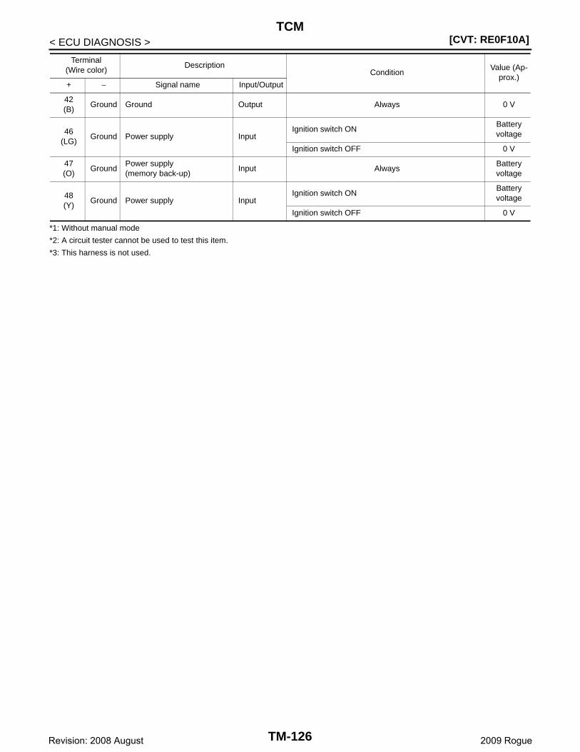
[CVT: RE0F10A]TCM
< ECU DIAGNOSIS >
*1: Without manual mode
*2: A circuit tester cannot be used to test this item.
*3: This harness is not used.
42(B)
Ground Ground Output Always 0 V
46(LG)
Ground Power supply InputIgnition switch ON
Battery voltage
Ignition switch OFF 0 V
47(O)
GroundPower supply(memory back-up)
Input AlwaysBattery voltage
48(Y)
Ground Power supply InputIgnition switch ON
Battery voltage
Ignition switch OFF 0 V
Terminal(Wire color)
DescriptionCondition
Value (Ap-prox.)
+ − Signal name Input/Output
TM-126Revision: 2008 August 2009 Rogue
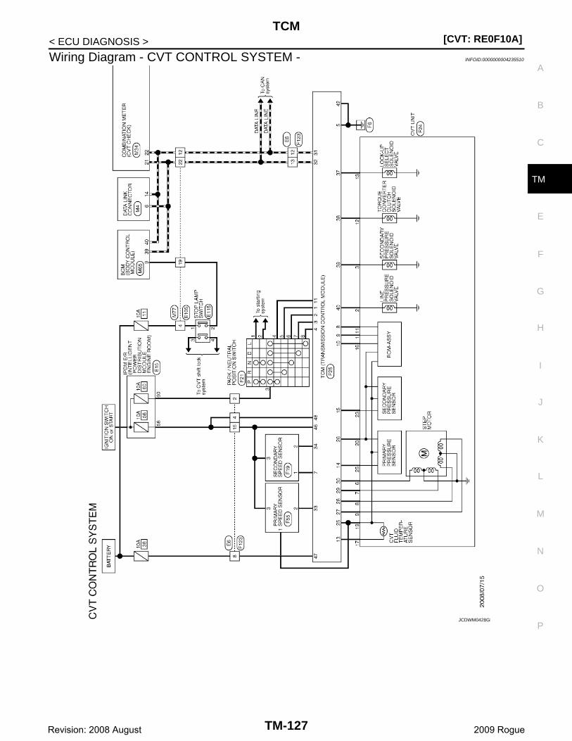
TCM[CVT: RE0F10A]
C
E
F
G
H
I
J
K
L
M
A
B
M
N
O
P
< ECU DIAGNOSIS >
T
Wiring Diagram - CVT CONTROL SYSTEM - INFOID:0000000004235510
JCDWM0428GB
TM-127Revision: 2008 August 2009 Rogue
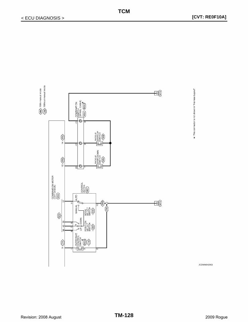
[CVT: RE0F10A]TCM
< ECU DIAGNOSIS >
JCDWM0429GB
TM-128Revision: 2008 August 2009 Rogue
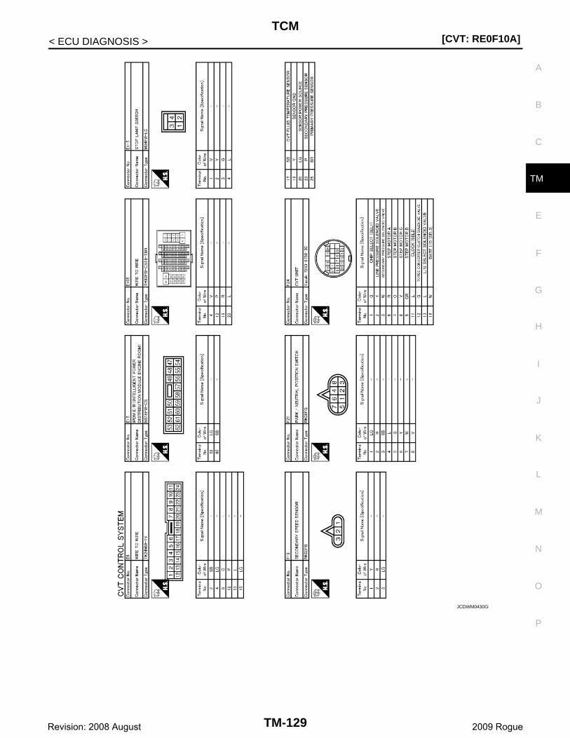
TCM[CVT: RE0F10A]
C
E
F
G
H
I
J
K
L
M
A
B
M
N
O
P
< ECU DIAGNOSIS >
T
JCDWM0430GB
TM-129Revision: 2008 August 2009 Rogue
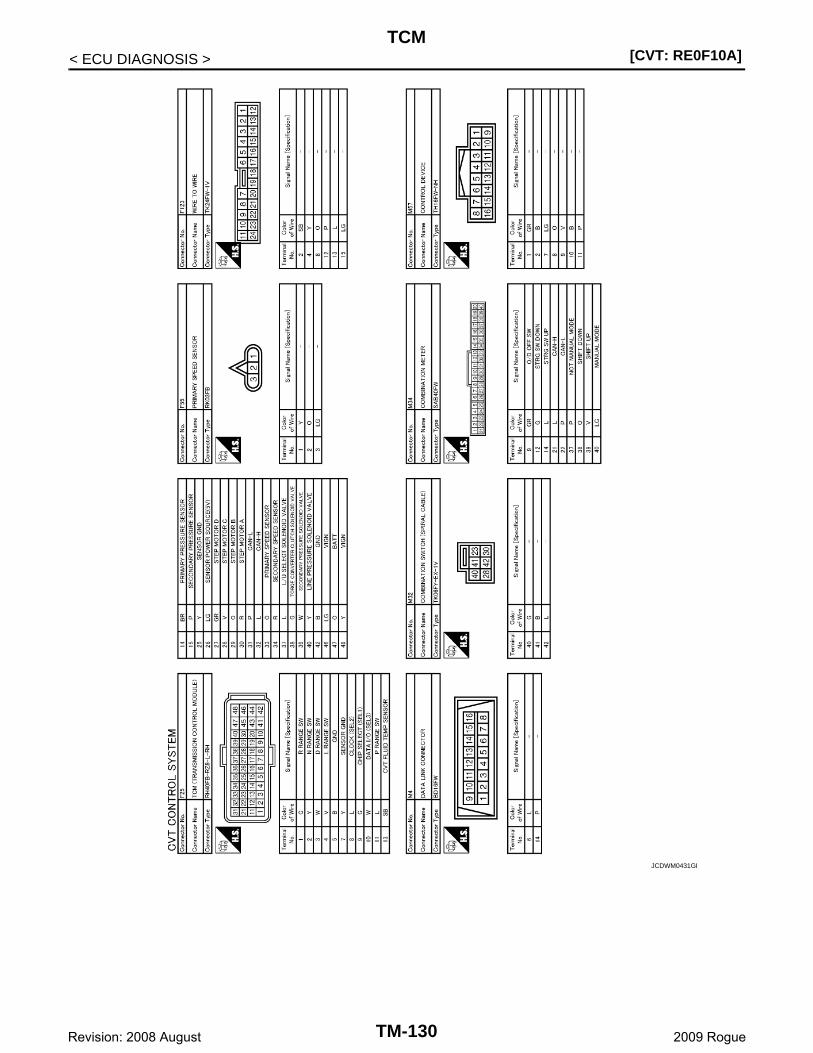
[CVT: RE0F10A]TCM
< ECU DIAGNOSIS >
JCDWM0431GB
TM-130Revision: 2008 August 2009 Rogue
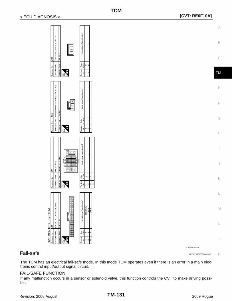
TCM[CVT: RE0F10A]
C
E
F
G
H
I
J
K
L
M
A
B
M
N
O
P
< ECU DIAGNOSIS >
T
Fail-safe INFOID:0000000004235511
The TCM has an electrical fail-safe mode. In this mode TCM operates even if there is an error in a main elec-tronic control input/output signal circuit.
FAIL-SAFE FUNCTION If any malfunction occurs in a sensor or solenoid valve, this function controls the CVT to make driving possi-ble.
JCDWM0432GB
TM-131Revision: 2008 August 2009 Rogue
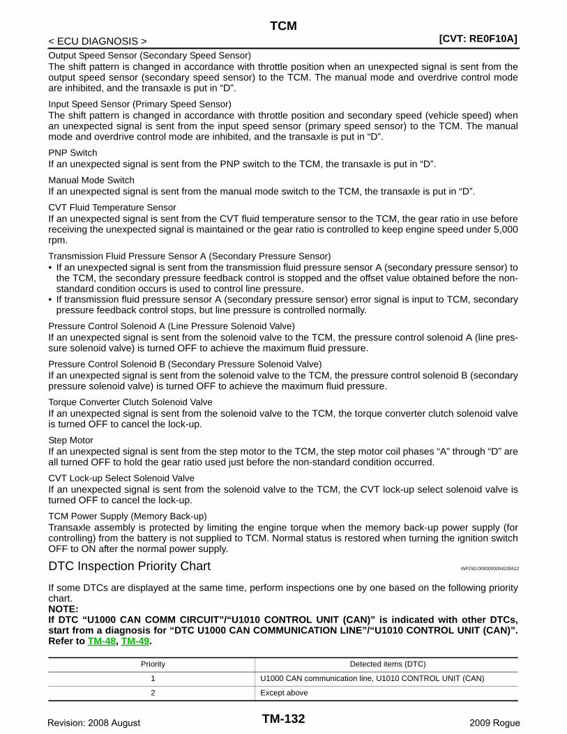
[CVT: RE0F10A]TCM
< ECU DIAGNOSIS >Output Speed Sensor (Secondary Speed Sensor)The shift pattern is changed in accordance with throttle position when an unexpected signal is sent from theoutput speed sensor (secondary speed sensor) to the TCM. The manual mode and overdrive control modeare inhibited, and the transaxle is put in “D”.
Input Speed Sensor (Primary Speed Sensor)The shift pattern is changed in accordance with throttle position and secondary speed (vehicle speed) whenan unexpected signal is sent from the input speed sensor (primary speed sensor) to the TCM. The manualmode and overdrive control mode are inhibited, and the transaxle is put in “D”.
PNP SwitchIf an unexpected signal is sent from the PNP switch to the TCM, the transaxle is put in “D”.
Manual Mode SwitchIf an unexpected signal is sent from the manual mode switch to the TCM, the transaxle is put in “D”.
CVT Fluid Temperature SensorIf an unexpected signal is sent from the CVT fluid temperature sensor to the TCM, the gear ratio in use beforereceiving the unexpected signal is maintained or the gear ratio is controlled to keep engine speed under 5,000rpm.
Transmission Fluid Pressure Sensor A (Secondary Pressure Sensor)• If an unexpected signal is sent from the transmission fluid pressure sensor A (secondary pressure sensor) to
the TCM, the secondary pressure feedback control is stopped and the offset value obtained before the non-standard condition occurs is used to control line pressure.
• If transmission fluid pressure sensor A (secondary pressure sensor) error signal is input to TCM, secondarypressure feedback control stops, but line pressure is controlled normally.
Pressure Control Solenoid A (Line Pressure Solenoid Valve)If an unexpected signal is sent from the solenoid valve to the TCM, the pressure control solenoid A (line pres-sure solenoid valve) is turned OFF to achieve the maximum fluid pressure.
Pressure Control Solenoid B (Secondary Pressure Solenoid Valve)If an unexpected signal is sent from the solenoid valve to the TCM, the pressure control solenoid B (secondarypressure solenoid valve) is turned OFF to achieve the maximum fluid pressure.
Torque Converter Clutch Solenoid ValveIf an unexpected signal is sent from the solenoid valve to the TCM, the torque converter clutch solenoid valveis turned OFF to cancel the lock-up.
Step MotorIf an unexpected signal is sent from the step motor to the TCM, the step motor coil phases “A” through “D” areall turned OFF to hold the gear ratio used just before the non-standard condition occurred.
CVT Lock-up Select Solenoid ValveIf an unexpected signal is sent from the solenoid valve to the TCM, the CVT lock-up select solenoid valve isturned OFF to cancel the lock-up.
TCM Power Supply (Memory Back-up)Transaxle assembly is protected by limiting the engine torque when the memory back-up power supply (forcontrolling) from the battery is not supplied to TCM. Normal status is restored when turning the ignition switchOFF to ON after the normal power supply.
DTC Inspection Priority Chart INFOID:0000000004235512
If some DTCs are displayed at the same time, perform inspections one by one based on the following prioritychart.NOTE:If DTC “U1000 CAN COMM CIRCUIT”/“U1010 CONTROL UNIT (CAN)” is indicated with other DTCs,start from a diagnosis for “DTC U1000 CAN COMMUNICATION LINE”/“U1010 CONTROL UNIT (CAN)”.Refer to TM-48, TM-49.
Priority Detected items (DTC)
1 U1000 CAN communication line, U1010 CONTROL UNIT (CAN)
2 Except above
TM-132Revision: 2008 August 2009 Rogue
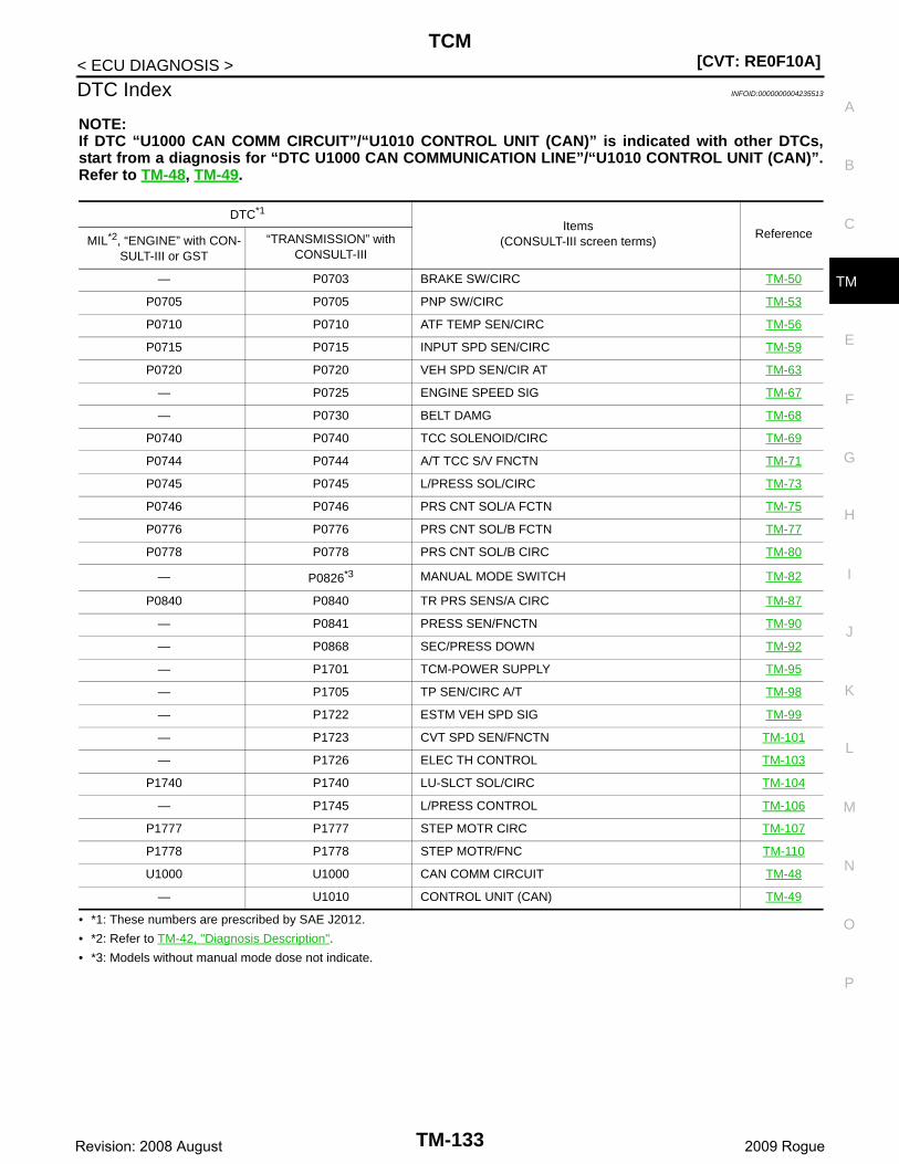
TCM[CVT: RE0F10A]
C
E
F
G
H
I
J
K
L
M
A
B
M
N
O
P
< ECU DIAGNOSIS >
T
DTC Index INFOID:0000000004235513
NOTE:If DTC “U1000 CAN COMM CIRCUIT”/“U1010 CONTROL UNIT (CAN)” is indicated with other DTCs,start from a diagnosis for “DTC U1000 CAN COMMUNICATION LINE”/“U1010 CONTROL UNIT (CAN)”.Refer to TM-48, TM-49.
• *1: These numbers are prescribed by SAE J2012.
• *2: Refer to TM-42, "Diagnosis Description".
• *3: Models without manual mode dose not indicate.
DTC*1
Items(CONSULT-III screen terms)
ReferenceMIL*2, “ENGINE” with CON-SULT-III or GST
“TRANSMISSION” with CONSULT-III
— P0703 BRAKE SW/CIRC TM-50
P0705 P0705 PNP SW/CIRC TM-53
P0710 P0710 ATF TEMP SEN/CIRC TM-56
P0715 P0715 INPUT SPD SEN/CIRC TM-59
P0720 P0720 VEH SPD SEN/CIR AT TM-63
— P0725 ENGINE SPEED SIG TM-67
— P0730 BELT DAMG TM-68
P0740 P0740 TCC SOLENOID/CIRC TM-69
P0744 P0744 A/T TCC S/V FNCTN TM-71
P0745 P0745 L/PRESS SOL/CIRC TM-73
P0746 P0746 PRS CNT SOL/A FCTN TM-75
P0776 P0776 PRS CNT SOL/B FCTN TM-77
P0778 P0778 PRS CNT SOL/B CIRC TM-80
— P0826*3 MANUAL MODE SWITCH TM-82
P0840 P0840 TR PRS SENS/A CIRC TM-87
— P0841 PRESS SEN/FNCTN TM-90
— P0868 SEC/PRESS DOWN TM-92
— P1701 TCM-POWER SUPPLY TM-95
— P1705 TP SEN/CIRC A/T TM-98
— P1722 ESTM VEH SPD SIG TM-99
— P1723 CVT SPD SEN/FNCTN TM-101
— P1726 ELEC TH CONTROL TM-103
P1740 P1740 LU-SLCT SOL/CIRC TM-104
— P1745 L/PRESS CONTROL TM-106
P1777 P1777 STEP MOTR CIRC TM-107
P1778 P1778 STEP MOTR/FNC TM-110
U1000 U1000 CAN COMM CIRCUIT TM-48
— U1010 CONTROL UNIT (CAN) TM-49
TM-133Revision: 2008 August 2009 Rogue
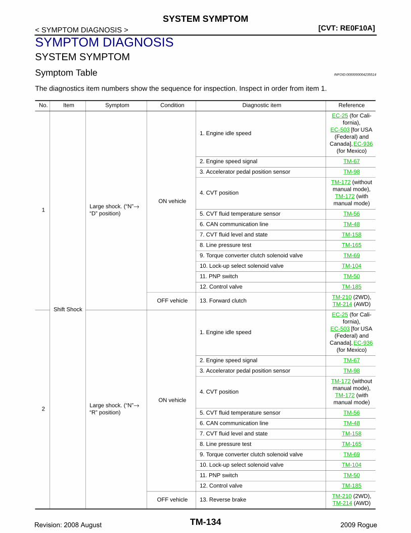
[CVT: RE0F10A]SYSTEM SYMPTOM
< SYMPTOM DIAGNOSIS >
SYMPTOM DIAGNOSISSYSTEM SYMPTOM
Symptom Table INFOID:0000000004235514
The diagnostics item numbers show the sequence for inspection. Inspect in order from item 1.
No. Item Symptom Condition Diagnostic item Reference
1
Shift Shock
Large shock. (“N”→ “D” position)
ON vehicle
1. Engine idle speed
EC-25 (for Cali-fornia),
EC-503 [for USA (Federal) and
Canada], EC-936 (for Mexico)
2. Engine speed signal TM-67
3. Accelerator pedal position sensor TM-98
4. CVT position
TM-172 (without manual mode), TM-172 (with manual mode)
5. CVT fluid temperature sensor TM-56
6. CAN communication line TM-48
7. CVT fluid level and state TM-158
8. Line pressure test TM-165
9. Torque converter clutch solenoid valve TM-69
10. Lock-up select solenoid valve TM-104
11. PNP switch TM-50
12. Control valve TM-185
OFF vehicle 13. Forward clutchTM-210 (2WD), TM-214 (AWD)
2Large shock. (“N”→ “R” position)
ON vehicle
1. Engine idle speed
EC-25 (for Cali-fornia),
EC-503 [for USA (Federal) and
Canada], EC-936 (for Mexico)
2. Engine speed signal TM-67
3. Accelerator pedal position sensor TM-98
4. CVT position
TM-172 (without manual mode), TM-172 (with manual mode)
5. CVT fluid temperature sensor TM-56
6. CAN communication line TM-48
7. CVT fluid level and state TM-158
8. Line pressure test TM-165
9. Torque converter clutch solenoid valve TM-69
10. Lock-up select solenoid valve TM-104
11. PNP switch TM-50
12. Control valve TM-185
OFF vehicle 13. Reverse brakeTM-210 (2WD), TM-214 (AWD)
TM-134Revision: 2008 August 2009 Rogue
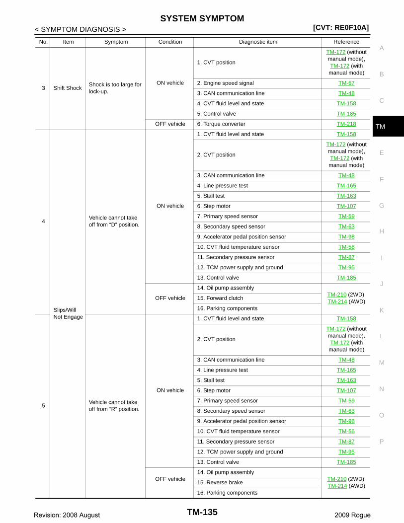
SYSTEM SYMPTOM[CVT: RE0F10A]
C
E
F
G
H
I
J
K
L
M
A
B
M
N
O
P
< SYMPTOM DIAGNOSIS >
T
3 Shift ShockShock is too large for lock-up.
ON vehicle
1. CVT position
TM-172 (without manual mode), TM-172 (with manual mode)
2. Engine speed signal TM-67
3. CAN communication line TM-48
4. CVT fluid level and state TM-158
5. Control valve TM-185
OFF vehicle 6. Torque converter TM-218
4
Slips/Will Not Engage
Vehicle cannot take off from “D” position.
ON vehicle
1. CVT fluid level and state TM-158
2. CVT position
TM-172 (without manual mode), TM-172 (with manual mode)
3. CAN communication line TM-48
4. Line pressure test TM-165
5. Stall test TM-163
6. Step motor TM-107
7. Primary speed sensor TM-59
8. Secondary speed sensor TM-63
9. Accelerator pedal position sensor TM-98
10. CVT fluid temperature sensor TM-56
11. Secondary pressure sensor TM-87
12. TCM power supply and ground TM-95
13. Control valve TM-185
OFF vehicle
14. Oil pump assemblyTM-210 (2WD), TM-214 (AWD)
15. Forward clutch
16. Parking components
5Vehicle cannot take off from “R” position.
ON vehicle
1. CVT fluid level and state TM-158
2. CVT position
TM-172 (without manual mode), TM-172 (with manual mode)
3. CAN communication line TM-48
4. Line pressure test TM-165
5. Stall test TM-163
6. Step motor TM-107
7. Primary speed sensor TM-59
8. Secondary speed sensor TM-63
9. Accelerator pedal position sensor TM-98
10. CVT fluid temperature sensor TM-56
11. Secondary pressure sensor TM-87
12. TCM power supply and ground TM-95
13. Control valve TM-185
OFF vehicle14. Oil pump assembly
TM-210 (2WD), TM-214 (AWD)
15. Reverse brake
16. Parking components
No. Item Symptom Condition Diagnostic item Reference
TM-135Revision: 2008 August 2009 Rogue

[CVT: RE0F10A]SYSTEM SYMPTOM
< SYMPTOM DIAGNOSIS >
6
Slips/Will Not Engage
Does not lock-up.
ON vehicle
1. CVT fluid level and state TM-158
2. Line pressure test TM-165
3. Engine speed signal TM-67
4. Primary speed sensor TM-59
5. Torque converter clutch solenoid valve TM-69
6. CAN communication line TM-48
7. Stall test TM-163
8. Step motor TM-107
9. PNP switch TM-50
10. Lock-up select solenoid valve TM-104
11. CVT fluid temperature sensor TM-56
12. Secondary speed sensor TM-63
13. Secondary pressure sensor TM-87
14. Control valve TM-185
OFF vehicle
15. Torque converter TM-218
16. Oil pump assemblyTM-210 (2WD), TM-214 (AWD)
7Does not hold lock-up condition.
ON vehicle
1. CVT fluid level and state TM-158
2. Line pressure test TM-165
3. Engine speed signal TM-67
4. Primary speed sensor TM-59
5. Torque converter clutch solenoid valve TM-69
6. CAN communication line TM-48
7. Stall test TM-163
8. Step motor TM-107
9. PNP switch TM-50
10. Lock-up select solenoid valve TM-104
11. CVT fluid temperature sensor TM-56
12. Secondary speed sensor TM-63
13. Secondary pressure sensor TM-87
14. Control valve TM-185
OFF vehicle
15. Torque converter TM-218
16. Oil pump assemblyTM-210 (2WD), TM-214 (AWD)
No. Item Symptom Condition Diagnostic item Reference
TM-136Revision: 2008 August 2009 Rogue
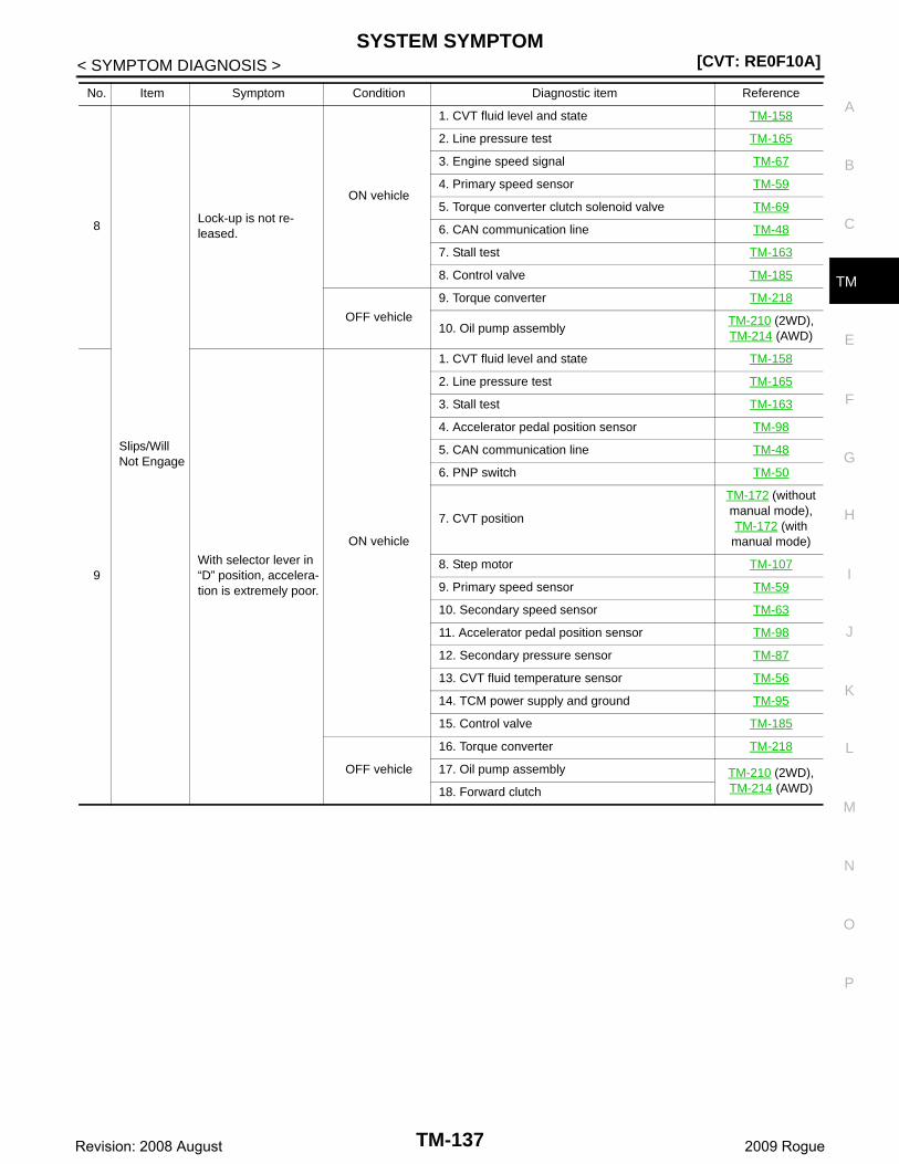
SYSTEM SYMPTOM[CVT: RE0F10A]
C
E
F
G
H
I
J
K
L
M
A
B
M
N
O
P
< SYMPTOM DIAGNOSIS >
T
8
Slips/Will Not Engage
Lock-up is not re-leased.
ON vehicle
1. CVT fluid level and state TM-158
2. Line pressure test TM-165
3. Engine speed signal TM-67
4. Primary speed sensor TM-59
5. Torque converter clutch solenoid valve TM-69
6. CAN communication line TM-48
7. Stall test TM-163
8. Control valve TM-185
OFF vehicle
9. Torque converter TM-218
10. Oil pump assemblyTM-210 (2WD), TM-214 (AWD)
9With selector lever in “D” position, accelera-tion is extremely poor.
ON vehicle
1. CVT fluid level and state TM-158
2. Line pressure test TM-165
3. Stall test TM-163
4. Accelerator pedal position sensor TM-98
5. CAN communication line TM-48
6. PNP switch TM-50
7. CVT position
TM-172 (without manual mode), TM-172 (with manual mode)
8. Step motor TM-107
9. Primary speed sensor TM-59
10. Secondary speed sensor TM-63
11. Accelerator pedal position sensor TM-98
12. Secondary pressure sensor TM-87
13. CVT fluid temperature sensor TM-56
14. TCM power supply and ground TM-95
15. Control valve TM-185
OFF vehicle
16. Torque converter TM-218
17. Oil pump assembly TM-210 (2WD), TM-214 (AWD)18. Forward clutch
No. Item Symptom Condition Diagnostic item Reference
TM-137Revision: 2008 August 2009 Rogue
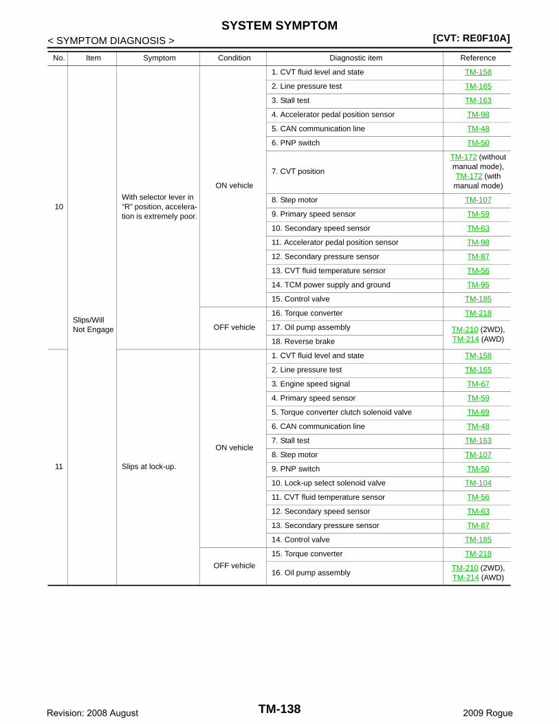
[CVT: RE0F10A]SYSTEM SYMPTOM
< SYMPTOM DIAGNOSIS >
10
Slips/Will Not Engage
With selector lever in “R” position, accelera-tion is extremely poor.
ON vehicle
1. CVT fluid level and state TM-158
2. Line pressure test TM-165
3. Stall test TM-163
4. Accelerator pedal position sensor TM-98
5. CAN communication line TM-48
6. PNP switch TM-50
7. CVT position
TM-172 (without manual mode), TM-172 (with manual mode)
8. Step motor TM-107
9. Primary speed sensor TM-59
10. Secondary speed sensor TM-63
11. Accelerator pedal position sensor TM-98
12. Secondary pressure sensor TM-87
13. CVT fluid temperature sensor TM-56
14. TCM power supply and ground TM-95
15. Control valve TM-185
OFF vehicle
16. Torque converter TM-218
17. Oil pump assembly TM-210 (2WD), TM-214 (AWD)18. Reverse brake
11 Slips at lock-up.
ON vehicle
1. CVT fluid level and state TM-158
2. Line pressure test TM-165
3. Engine speed signal TM-67
4. Primary speed sensor TM-59
5. Torque converter clutch solenoid valve TM-69
6. CAN communication line TM-48
7. Stall test TM-163
8. Step motor TM-107
9. PNP switch TM-50
10. Lock-up select solenoid valve TM-104
11. CVT fluid temperature sensor TM-56
12. Secondary speed sensor TM-63
13. Secondary pressure sensor TM-87
14. Control valve TM-185
OFF vehicle
15. Torque converter TM-218
16. Oil pump assemblyTM-210 (2WD), TM-214 (AWD)
No. Item Symptom Condition Diagnostic item Reference
TM-138Revision: 2008 August 2009 Rogue
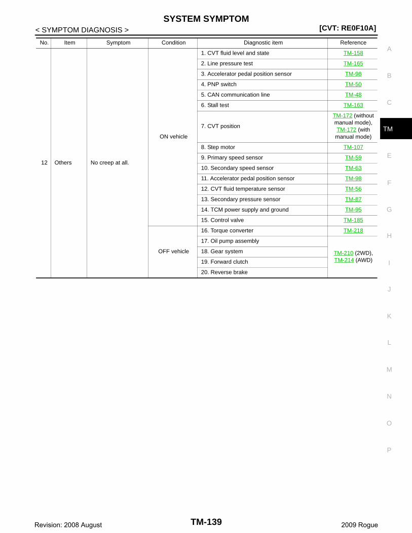
SYSTEM SYMPTOM[CVT: RE0F10A]
C
E
F
G
H
I
J
K
L
M
A
B
M
N
O
P
< SYMPTOM DIAGNOSIS >
T
12 Others No creep at all.
ON vehicle
1. CVT fluid level and state TM-158
2. Line pressure test TM-165
3. Accelerator pedal position sensor TM-98
4. PNP switch TM-50
5. CAN communication line TM-48
6. Stall test TM-163
7. CVT position
TM-172 (without manual mode), TM-172 (with manual mode)
8. Step motor TM-107
9. Primary speed sensor TM-59
10. Secondary speed sensor TM-63
11. Accelerator pedal position sensor TM-98
12. CVT fluid temperature sensor TM-56
13. Secondary pressure sensor TM-87
14. TCM power supply and ground TM-95
15. Control valve TM-185
OFF vehicle
16. Torque converter TM-218
17. Oil pump assembly
TM-210 (2WD), TM-214 (AWD)
18. Gear system
19. Forward clutch
20. Reverse brake
No. Item Symptom Condition Diagnostic item Reference
TM-139Revision: 2008 August 2009 Rogue
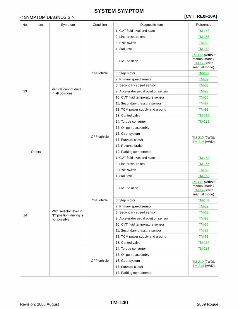
[CVT: RE0F10A]SYSTEM SYMPTOM
< SYMPTOM DIAGNOSIS >
13
Others
Vehicle cannot drive in all positions.
ON vehicle
1. CVT fluid level and state TM-158
2. Line pressure test TM-165
3. PNP switch TM-50
4. Stall test TM-163
5. CVT position
TM-172 (without manual mode), TM-172 (with manual mode)
6. Step motor TM-107
7. Primary speed sensor TM-59
8. Secondary speed sensor TM-63
9. Accelerator pedal position sensor TM-98
10. CVT fluid temperature sensor TM-56
11. Secondary pressure sensor TM-87
12. TCM power supply and ground TM-95
13. Control valve TM-185
OFF vehicle
14. Torque converter TM-218
15. Oil pump assembly
TM-210 (2WD), TM-214 (AWD)
16. Gear system
17. Forward clutch
18. Reverse brake
19. Parking components
14With selector lever in “D” position, driving is not possible.
ON vehicle
1. CVT fluid level and state TM-158
2. Line pressure test TM-165
3. PNP switch TM-50
4. Stall test TM-163
5. CVT position
TM-172 (without manual mode), TM-172 (with manual mode)
6. Step motor TM-107
7. Primary speed sensor TM-59
8. Secondary speed sensor TM-63
9. Accelerator pedal position sensor TM-98
10. CVT fluid temperature sensor TM-56
11. Secondary pressure sensor TM-87
12. TCM power supply and ground TM-95
13. Control valve TM-185
OFF vehicle
14. Torque converter TM-218
15. Oil pump assembly
TM-210 (2WD), TM-214 (AWD)
16. Gear system
17. Forward clutch
18. Parking components
No. Item Symptom Condition Diagnostic item Reference
TM-140Revision: 2008 August 2009 Rogue
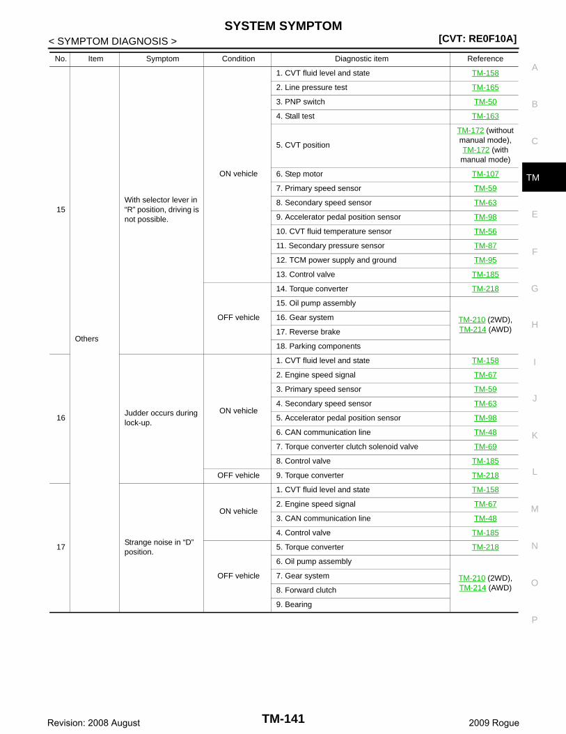
SYSTEM SYMPTOM[CVT: RE0F10A]
C
E
F
G
H
I
J
K
L
M
A
B
M
N
O
P
< SYMPTOM DIAGNOSIS >
T
15
Others
With selector lever in “R” position, driving is not possible.
ON vehicle
1. CVT fluid level and state TM-158
2. Line pressure test TM-165
3. PNP switch TM-50
4. Stall test TM-163
5. CVT position
TM-172 (without manual mode), TM-172 (with manual mode)
6. Step motor TM-107
7. Primary speed sensor TM-59
8. Secondary speed sensor TM-63
9. Accelerator pedal position sensor TM-98
10. CVT fluid temperature sensor TM-56
11. Secondary pressure sensor TM-87
12. TCM power supply and ground TM-95
13. Control valve TM-185
OFF vehicle
14. Torque converter TM-218
15. Oil pump assembly
TM-210 (2WD), TM-214 (AWD)
16. Gear system
17. Reverse brake
18. Parking components
16Judder occurs during lock-up.
ON vehicle
1. CVT fluid level and state TM-158
2. Engine speed signal TM-67
3. Primary speed sensor TM-59
4. Secondary speed sensor TM-63
5. Accelerator pedal position sensor TM-98
6. CAN communication line TM-48
7. Torque converter clutch solenoid valve TM-69
8. Control valve TM-185
OFF vehicle 9. Torque converter TM-218
17Strange noise in “D” position.
ON vehicle
1. CVT fluid level and state TM-158
2. Engine speed signal TM-67
3. CAN communication line TM-48
4. Control valve TM-185
OFF vehicle
5. Torque converter TM-218
6. Oil pump assembly
TM-210 (2WD), TM-214 (AWD)
7. Gear system
8. Forward clutch
9. Bearing
No. Item Symptom Condition Diagnostic item Reference
TM-141Revision: 2008 August 2009 Rogue
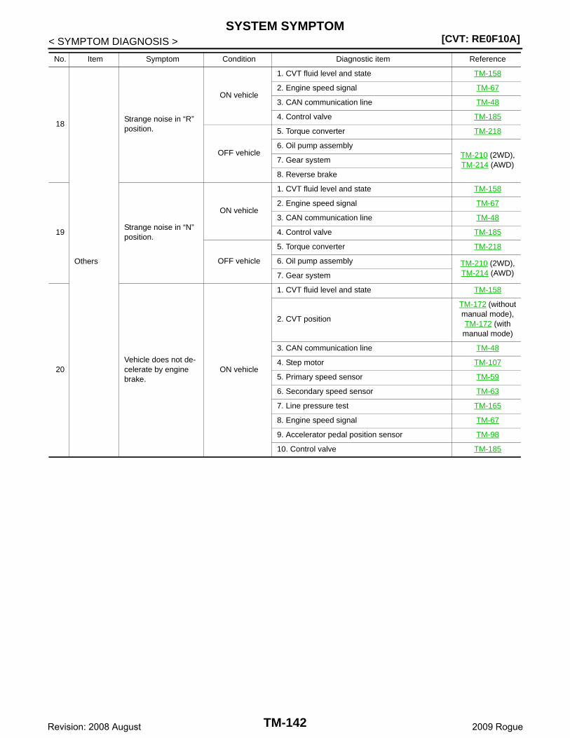
[CVT: RE0F10A]SYSTEM SYMPTOM
< SYMPTOM DIAGNOSIS >
18
Others
Strange noise in “R” position.
ON vehicle
1. CVT fluid level and state TM-158
2. Engine speed signal TM-67
3. CAN communication line TM-48
4. Control valve TM-185
OFF vehicle
5. Torque converter TM-218
6. Oil pump assemblyTM-210 (2WD), TM-214 (AWD)
7. Gear system
8. Reverse brake
19Strange noise in “N” position.
ON vehicle
1. CVT fluid level and state TM-158
2. Engine speed signal TM-67
3. CAN communication line TM-48
4. Control valve TM-185
OFF vehicle
5. Torque converter TM-218
6. Oil pump assembly TM-210 (2WD), TM-214 (AWD)7. Gear system
20Vehicle does not de-celerate by engine brake.
ON vehicle
1. CVT fluid level and state TM-158
2. CVT position
TM-172 (without manual mode), TM-172 (with manual mode)
3. CAN communication line TM-48
4. Step motor TM-107
5. Primary speed sensor TM-59
6. Secondary speed sensor TM-63
7. Line pressure test TM-165
8. Engine speed signal TM-67
9. Accelerator pedal position sensor TM-98
10. Control valve TM-185
No. Item Symptom Condition Diagnostic item Reference
TM-142Revision: 2008 August 2009 Rogue
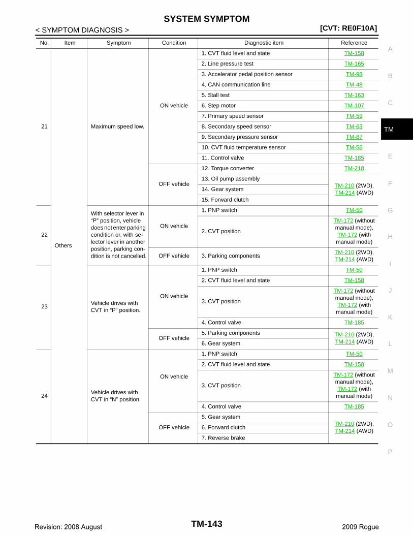
SYSTEM SYMPTOM[CVT: RE0F10A]
C
E
F
G
H
I
J
K
L
M
A
B
M
N
O
P
< SYMPTOM DIAGNOSIS >
T21
Others
Maximum speed low.
ON vehicle
1. CVT fluid level and state TM-158
2. Line pressure test TM-165
3. Accelerator pedal position sensor TM-98
4. CAN communication line TM-48
5. Stall test TM-163
6. Step motor TM-107
7. Primary speed sensor TM-59
8. Secondary speed sensor TM-63
9. Secondary pressure sensor TM-87
10. CVT fluid temperature sensor TM-56
11. Control valve TM-185
OFF vehicle
12. Torque converter TM-218
13. Oil pump assemblyTM-210 (2WD), TM-214 (AWD)
14. Gear system
15. Forward clutch
22
With selector lever in “P” position, vehicle does not enter parking condition or, with se-lector lever in another position, parking con-dition is not cancelled.
ON vehicle
1. PNP switch TM-50
2. CVT position
TM-172 (without manual mode), TM-172 (with manual mode)
OFF vehicle 3. Parking componentsTM-210 (2WD), TM-214 (AWD)
23Vehicle drives with CVT in “P” position.
ON vehicle
1. PNP switch TM-50
2. CVT fluid level and state TM-158
3. CVT position
TM-172 (without manual mode), TM-172 (with manual mode)
4. Control valve TM-185
OFF vehicle5. Parking components TM-210 (2WD),
TM-214 (AWD)6. Gear system
24Vehicle drives with CVT in “N” position.
ON vehicle
1. PNP switch TM-50
2. CVT fluid level and state TM-158
3. CVT position
TM-172 (without manual mode), TM-172 (with manual mode)
4. Control valve TM-185
OFF vehicle
5. Gear systemTM-210 (2WD), TM-214 (AWD)
6. Forward clutch
7. Reverse brake
No. Item Symptom Condition Diagnostic item Reference
TM-143Revision: 2008 August 2009 Rogue
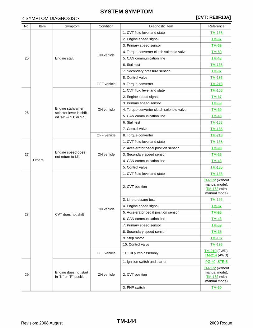
[CVT: RE0F10A]SYSTEM SYMPTOM
< SYMPTOM DIAGNOSIS >
25
Others
Engine stall.ON vehicle
1. CVT fluid level and state TM-158
2. Engine speed signal TM-67
3. Primary speed sensor TM-59
4. Torque converter clutch solenoid valve TM-69
5. CAN communication line TM-48
6. Stall test TM-163
7. Secondary pressure sensor TM-87
8. Control valve TM-185
OFF vehicle 9. Torque converter TM-218
26Engine stalls when selector lever is shift-ed “N” → “D” or “R”.
ON vehicle
1. CVT fluid level and state TM-158
2. Engine speed signal TM-67
3. Primary speed sensor TM-59
4. Torque converter clutch solenoid valve TM-69
5. CAN communication line TM-48
6. Stall test TM-163
7. Control valve TM-185
OFF vehicle 8. Torque converter TM-218
27Engine speed does not return to idle.
ON vehicle
1. CVT fluid level and state TM-158
2. Accelerator pedal position sensor TM-98
3. Secondary speed sensor TM-63
4. CAN communication line TM-48
5. Control valve TM-185
28 CVT does not shift
ON vehicle
1. CVT fluid level and state TM-158
2. CVT position
TM-172 (without manual mode), TM-172 (with manual mode)
3. Line pressure test TM-165
4. Engine speed signal TM-67
5. Accelerator pedal position sensor TM-98
6. CAN communication line TM-48
7. Primary speed sensor TM-59
8. Secondary speed sensor TM-63
9. Step motor TM-107
10. Control valve TM-185
OFF vehicle 11. Oil pump assemblyTM-210 (2WD), TM-214 (AWD)
29Engine does not start in “N” or “P” position.
ON vehicle
1. Ignition switch and starter PG-40, STR-5
2. CVT position
TM-172 (without manual mode), TM-172 (with manual mode)
3. PNP switch TM-50
No. Item Symptom Condition Diagnostic item Reference
TM-144Revision: 2008 August 2009 Rogue
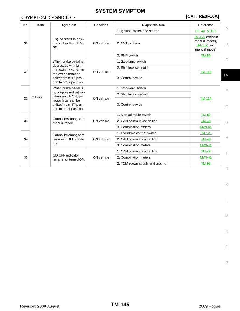
SYSTEM SYMPTOM[CVT: RE0F10A]
C
E
F
G
H
I
J
K
L
M
A
B
M
N
O
P
< SYMPTOM DIAGNOSIS >
T
30
Others
Engine starts in posi-tions other than “N” or “P”.
ON vehicle
1. Ignition switch and starter PG-40, STR-5
2. CVT position
TM-172 (without manual mode), TM-172 (with manual mode)
3. PNP switch TM-50
31
When brake pedal is depressed with igni-tion switch ON, selec-tor lever cannot be shifted from “P” posi-tion to other position.
ON vehicle
1. Stop lamp switch
TM-1142. Shift lock solenoid
3. Control device
32
When brake pedal is not depressed with ig-nition switch ON, se-lector lever can be shifted from “P” posi-tion to other position.
ON vehicle
1. Stop lamp switch
TM-1142. Shift lock solenoid
3. Control device
33Cannot be changed to manual mode.
ON vehicle
1. Manual mode switch TM-82
2. CAN communication line TM-48
3. Combination meters MWI-41
34Cannot be changed to overdrive OFF condi-tion.
ON vehicle
1. Overdrive control switch TM-120
2. CAN communication line TM-48
3. Combination meters MWI-41
35OD OFF indicator lamp is not turned ON.
ON vehicle
1. CAN communication line TM-48
2. Combination meters MWI-41
3. TCM power supply and ground TM-95
No. Item Symptom Condition Diagnostic item Reference
TM-145Revision: 2008 August 2009 Rogue
[CVT: RE0F10A]PRECAUTIONS
< PRECAUTION >
PRECAUTIONPRECAUTIONSFOR USA AND CANADA
FOR USA AND CANADA : Precaution for Supplemental Restraint System (SRS) "AIR BAG" and "SEAT BELT PRE-TENSIONER" INFOID:0000000004235515
The Supplemental Restraint System such as “AIR BAG” and “SEAT BELT PRE-TENSIONER”, used alongwith a front seat belt, helps to reduce the risk or severity of injury to the driver and front passenger for certaintypes of collision. This system includes seat belt switch inputs and dual stage front air bag modules. The SRSsystem uses the seat belt switches to determine the front air bag deployment, and may only deploy one frontair bag, depending on the severity of a collision and whether the front occupants are belted or unbelted.Information necessary to service the system safely is included in the “SRS AIRBAG” and “SEAT BELT” of thisService Manual.WARNING:• To avoid rendering the SRS inoperative, which could increase the risk of personal injury or death in
the event of a collision which would result in air bag inflation, all maintenance must be performed byan authorized NISSAN/INFINITI dealer.
• Improper maintenance, including incorrect removal and installation of the SRS, can lead to personalinjury caused by unintentional activation of the system. For removal of Spiral Cable and Air BagModule, see the “SRS AIRBAG”.
• Never use electrical test equipment on any circuit related to the SRS unless instructed to in this Ser-vice Manual. SRS wiring harnesses can be identified by yellow and/or orange harnesses or harnessconnectors.
FOR USA AND CANADA : Precaution Necessary for Steering Wheel Rotation After Battery Disconnect INFOID:0000000004235516
NOTE:• This Procedure is applied only to models with Intelligent Key system and NVIS/IVIS (NISSAN/INFINITI
VEHICLE IMMOBILIZER SYSTEM - NATS).• Remove and install all control units after disconnecting both battery cables with the ignition knob in the
″LOCK″ position.• Always use CONSULT-III to perform self-diagnosis as a part of each function inspection after finishing work.
If DTC is detected, perform trouble diagnosis according to self-diagnostic results.For models equipped with the Intelligent Key system and NVIS/IVIS, an electrically controlled steering lockmechanism is adopted on the key cylinder.For this reason, if the battery is disconnected or if the battery is discharged, the steering wheel will lock andsteering wheel rotation will become impossible.If steering wheel rotation is required when battery power is interrupted, follow the procedure below beforestarting the repair operation.
OPERATION PROCEDURE1. Connect both battery cables.
NOTE:Supply power using jumper cables if battery is discharged.
2. Use the Intelligent Key or mechanical key to turn the ignition switch to the ″ACC″ position. At this time, thesteering lock will be released.
3. Disconnect both battery cables. The steering lock will remain released and the steering wheel can berotated.
4. Perform the necessary repair operation.5. When the repair work is completed, return the ignition switch to the ″LOCK″ position before connecting
the battery cables. (At this time, the steering lock mechanism will engage.)6. Perform a self-diagnosis check of all control units using CONSULT-III.
TM-146Revision: 2008 August 2009 Rogue
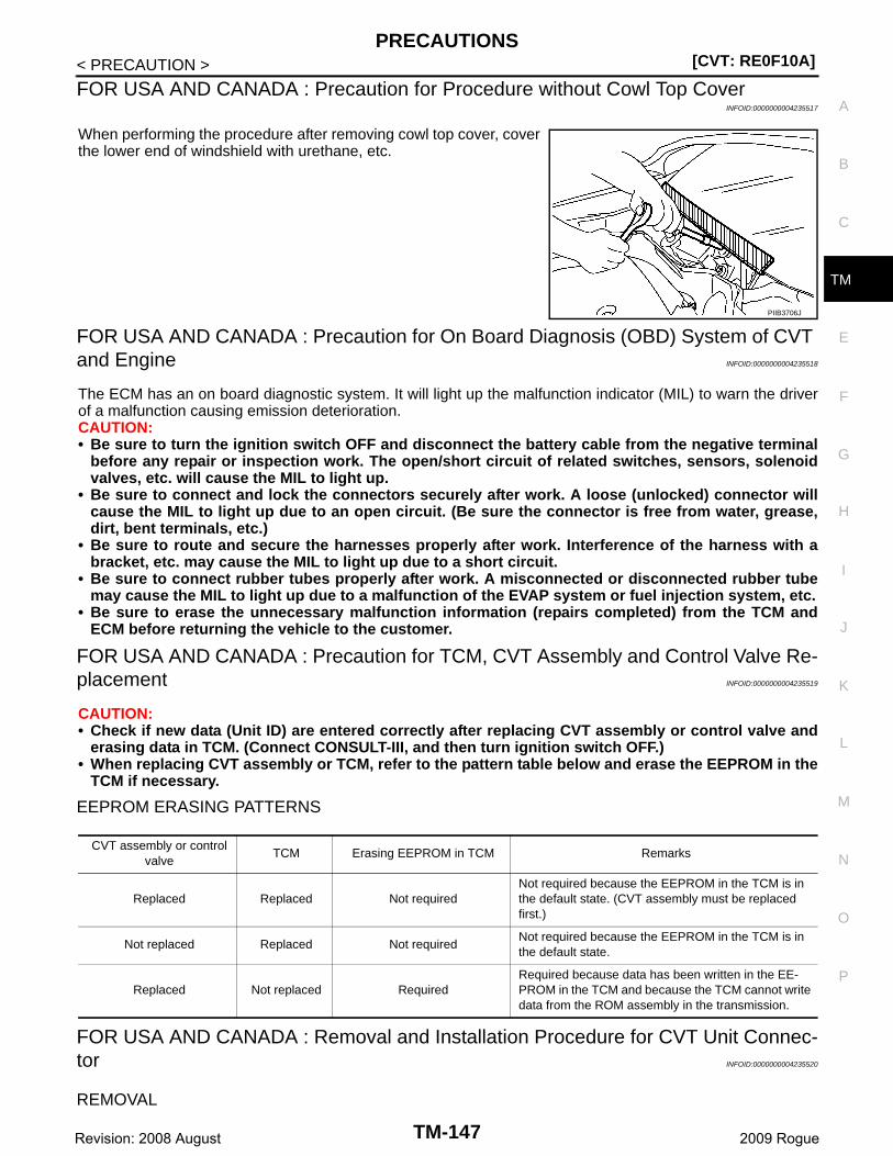
PRECAUTIONS[CVT: RE0F10A]
C
E
F
G
H
I
J
K
L
M
A
B
M
N
O
P
< PRECAUTION >
T
FOR USA AND CANADA : Precaution for Procedure without Cowl Top CoverINFOID:0000000004235517
When performing the procedure after removing cowl top cover, coverthe lower end of windshield with urethane, etc.
FOR USA AND CANADA : Precaution for On Board Diagnosis (OBD) System of CVT and Engine INFOID:0000000004235518
The ECM has an on board diagnostic system. It will light up the malfunction indicator (MIL) to warn the driverof a malfunction causing emission deterioration.CAUTION:• Be sure to turn the ignition switch OFF and disconnect the battery cable from the negative terminal
before any repair or inspection work. The open/short circuit of related switches, sensors, solenoidvalves, etc. will cause the MIL to light up.
• Be sure to connect and lock the connectors securely after work. A loose (unlocked) connector willcause the MIL to light up due to an open circuit. (Be sure the connector is free from water, grease,dirt, bent terminals, etc.)
• Be sure to route and secure the harnesses properly after work. Interference of the harness with abracket, etc. may cause the MIL to light up due to a short circuit.
• Be sure to connect rubber tubes properly after work. A misconnected or disconnected rubber tubemay cause the MIL to light up due to a malfunction of the EVAP system or fuel injection system, etc.
• Be sure to erase the unnecessary malfunction information (repairs completed) from the TCM andECM before returning the vehicle to the customer.
FOR USA AND CANADA : Precaution for TCM, CVT Assembly and Control Valve Re-placement INFOID:0000000004235519
CAUTION:• Check if new data (Unit ID) are entered correctly after replacing CVT assembly or control valve and
erasing data in TCM. (Connect CONSULT-III, and then turn ignition switch OFF.)• When replacing CVT assembly or TCM, refer to the pattern table below and erase the EEPROM in the
TCM if necessary.
EEPROM ERASING PATTERNS
FOR USA AND CANADA : Removal and Installation Procedure for CVT Unit Connec-tor INFOID:0000000004235520
REMOVAL
PIIB3706J
CVT assembly or control valve
TCM Erasing EEPROM in TCM Remarks
Replaced Replaced Not requiredNot required because the EEPROM in the TCM is in the default state. (CVT assembly must be replaced first.)
Not replaced Replaced Not requiredNot required because the EEPROM in the TCM is in the default state.
Replaced Not replaced RequiredRequired because data has been written in the EE-PROM in the TCM and because the TCM cannot write data from the ROM assembly in the transmission.
TM-147Revision: 2008 August 2009 Rogue
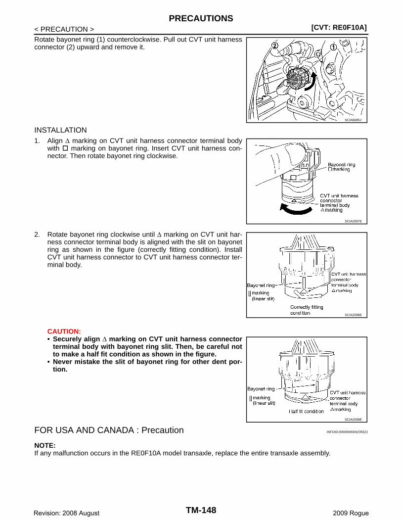
[CVT: RE0F10A]PRECAUTIONS
< PRECAUTION >Rotate bayonet ring (1) counterclockwise. Pull out CVT unit harnessconnector (2) upward and remove it.
INSTALLATION1. Align ∆ marking on CVT unit harness connector terminal body
with marking on bayonet ring. Insert CVT unit harness con-nector. Then rotate bayonet ring clockwise.
2. Rotate bayonet ring clockwise until ∆ marking on CVT unit har-ness connector terminal body is aligned with the slit on bayonetring as shown in the figure (correctly fitting condition). InstallCVT unit harness connector to CVT unit harness connector ter-minal body.
CAUTION:• Securely align ∆ marking on CVT unit harness connector
terminal body with bayonet ring slit. Then, be careful notto make a half fit condition as shown in the figure.
• Never mistake the slit of bayonet ring for other dent por-tion.
FOR USA AND CANADA : Precaution INFOID:0000000004235521
NOTE:If any malfunction occurs in the RE0F10A model transaxle, replace the entire transaxle assembly.
SCIA6685J
SCIA2097E
SCIA2098E
SCIA2099E
TM-148Revision: 2008 August 2009 Rogue
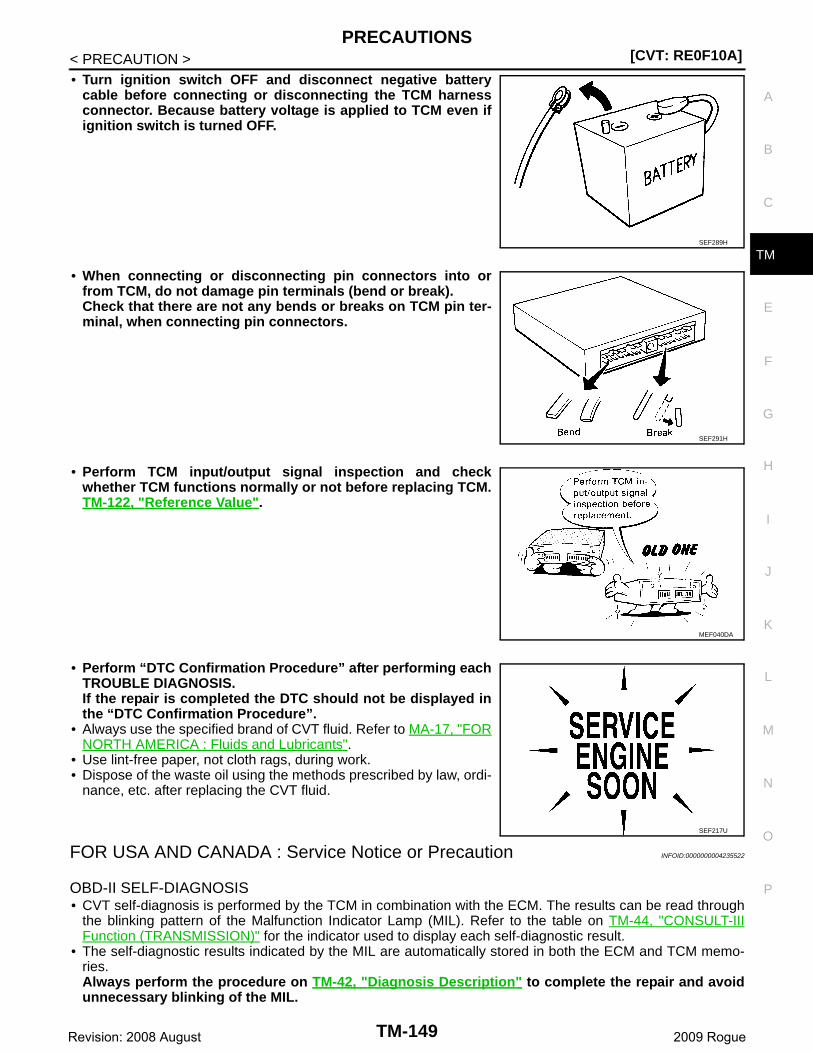
PRECAUTIONS[CVT: RE0F10A]
C
E
F
G
H
I
J
K
L
M
A
B
M
N
O
P
< PRECAUTION >
T
• Turn ignition switch OFF and disconnect negative batterycable before connecting or disconnecting the TCM harnessconnector. Because battery voltage is applied to TCM even ifignition switch is turned OFF.
• When connecting or disconnecting pin connectors into orfrom TCM, do not damage pin terminals (bend or break).Check that there are not any bends or breaks on TCM pin ter-minal, when connecting pin connectors.
• Perform TCM input/output signal inspection and checkwhether TCM functions normally or not before replacing TCM.TM-122, "Reference Value".
• Perform “DTC Confirmation Procedure” after performing eachTROUBLE DIAGNOSIS.If the repair is completed the DTC should not be displayed inthe “DTC Confirmation Procedure”.
• Always use the specified brand of CVT fluid. Refer to MA-17, "FORNORTH AMERICA : Fluids and Lubricants".
• Use lint-free paper, not cloth rags, during work.• Dispose of the waste oil using the methods prescribed by law, ordi-
nance, etc. after replacing the CVT fluid.
FOR USA AND CANADA : Service Notice or Precaution INFOID:0000000004235522
OBD-II SELF-DIAGNOSIS• CVT self-diagnosis is performed by the TCM in combination with the ECM. The results can be read through
the blinking pattern of the Malfunction Indicator Lamp (MIL). Refer to the table on TM-44, "CONSULT-IIIFunction (TRANSMISSION)" for the indicator used to display each self-diagnostic result.
• The self-diagnostic results indicated by the MIL are automatically stored in both the ECM and TCM memo-ries.Always perform the procedure on TM-42, "Diagnosis Description" to complete the repair and avoidunnecessary blinking of the MIL.
SEF289H
SEF291H
MEF040DA
SEF217U
TM-149Revision: 2008 August 2009 Rogue

[CVT: RE0F10A]PRECAUTIONS
< PRECAUTION >For details of OBD-II, refer to EC-92, "Diagnosis Description" (for California), EC-576, "CONSULT-III Function"[for USA (Federal) and Canada].• Certain systems and components, especially those related to OBD, may use the new style slide-lock-
ing type harness connector. For description and how to disconnect, refer to PG-82.
FOR USA AND CANADA : ATFTEMP COUNT Conversion Table INFOID:0000000004235523
FOR MEXICO
FOR MEXICO : Precaution for Supplemental Restraint System (SRS) "AIR BAG" and "SEAT BELT PRE-TENSIONER" INFOID:0000000004235524
The Supplemental Restraint System such as “AIR BAG” and “SEAT BELT PRE-TENSIONER”, used alongwith a front seat belt, helps to reduce the risk or severity of injury to the driver and front passenger for certaintypes of collision. Information necessary to service the system safely is included in the “SRS AIRBAG” and“SEAT BELT” of this Service Manual.WARNING:• To avoid rendering the SRS inoperative, which could increase the risk of personal injury or death in
the event of a collision which would result in air bag inflation, all maintenance must be performed byan authorized NISSAN/INFINITI dealer.
• Improper maintenance, including incorrect removal and installation of the SRS, can lead to personalinjury caused by unintentional activation of the system. For removal of Spiral Cable and Air BagModule, see the “SRS AIRBAG”.
• Do not use electrical test equipment on any circuit related to the SRS unless instructed to in thisService Manual. SRS wiring harnesses can be identified by yellow and/or orange harnesses or har-ness connectors.
FOR MEXICO : Precaution Necessary for Steering Wheel Rotation After Battery Dis-
ATFTEMP COUNT Temperature °C (°F) ATFTEMP COUNT Temperature °C (°F)
4 –30 (–22) 177 90 (194)
8 –20 (–4) 183 95 (203)
13 –10 (14) 190 100 (212)
17 –5 (23) 196 105 (221)
21 0 (32) 201 110 (230)
27 5 (41) 206 115 (239)
32 10 (50) 210 120 (248)
39 15 (59) 214 125 (257)
47 20 (68) 218 130 (266)
55 25 (77) 221 135 (275)
64 30 (86) 224 140 (284)
73 35 (95) 227 145 (293)
83 40 (104) 229 150 (302)
93 45 (113) 231 155 (311)
104 50 (122) 233 160 (320)
114 55 (131) 235 165 (329)
124 60 (140) 236 170 (338)
134 65 (149) 238 175 (347)
143 70 (158) 239 180 (356)
152 75 (167) 241 190 (374)
161 80 (176) 243 200 (392)
169 85 (185) — —
TM-150Revision: 2008 August 2009 Rogue
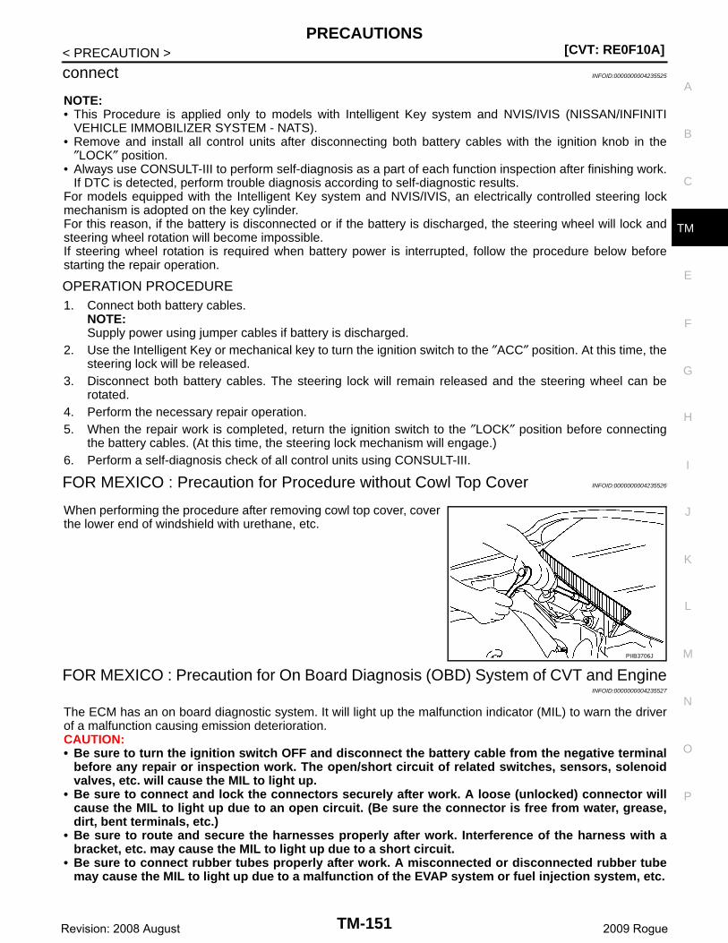
PRECAUTIONS[CVT: RE0F10A]
C
E
F
G
H
I
J
K
L
M
A
B
M
N
O
P
< PRECAUTION >
T
connect INFOID:0000000004235525
NOTE:• This Procedure is applied only to models with Intelligent Key system and NVIS/IVIS (NISSAN/INFINITI
VEHICLE IMMOBILIZER SYSTEM - NATS).• Remove and install all control units after disconnecting both battery cables with the ignition knob in the
″LOCK″ position.• Always use CONSULT-III to perform self-diagnosis as a part of each function inspection after finishing work.
If DTC is detected, perform trouble diagnosis according to self-diagnostic results.For models equipped with the Intelligent Key system and NVIS/IVIS, an electrically controlled steering lockmechanism is adopted on the key cylinder.For this reason, if the battery is disconnected or if the battery is discharged, the steering wheel will lock andsteering wheel rotation will become impossible.If steering wheel rotation is required when battery power is interrupted, follow the procedure below beforestarting the repair operation.
OPERATION PROCEDURE1. Connect both battery cables.
NOTE:Supply power using jumper cables if battery is discharged.
2. Use the Intelligent Key or mechanical key to turn the ignition switch to the ″ACC″ position. At this time, thesteering lock will be released.
3. Disconnect both battery cables. The steering lock will remain released and the steering wheel can berotated.
4. Perform the necessary repair operation.5. When the repair work is completed, return the ignition switch to the ″LOCK″ position before connecting
the battery cables. (At this time, the steering lock mechanism will engage.)6. Perform a self-diagnosis check of all control units using CONSULT-III.
FOR MEXICO : Precaution for Procedure without Cowl Top Cover INFOID:0000000004235526
When performing the procedure after removing cowl top cover, coverthe lower end of windshield with urethane, etc.
FOR MEXICO : Precaution for On Board Diagnosis (OBD) System of CVT and EngineINFOID:0000000004235527
The ECM has an on board diagnostic system. It will light up the malfunction indicator (MIL) to warn the driverof a malfunction causing emission deterioration.CAUTION:• Be sure to turn the ignition switch OFF and disconnect the battery cable from the negative terminal
before any repair or inspection work. The open/short circuit of related switches, sensors, solenoidvalves, etc. will cause the MIL to light up.
• Be sure to connect and lock the connectors securely after work. A loose (unlocked) connector willcause the MIL to light up due to an open circuit. (Be sure the connector is free from water, grease,dirt, bent terminals, etc.)
• Be sure to route and secure the harnesses properly after work. Interference of the harness with abracket, etc. may cause the MIL to light up due to a short circuit.
• Be sure to connect rubber tubes properly after work. A misconnected or disconnected rubber tubemay cause the MIL to light up due to a malfunction of the EVAP system or fuel injection system, etc.
PIIB3706J
TM-151Revision: 2008 August 2009 Rogue
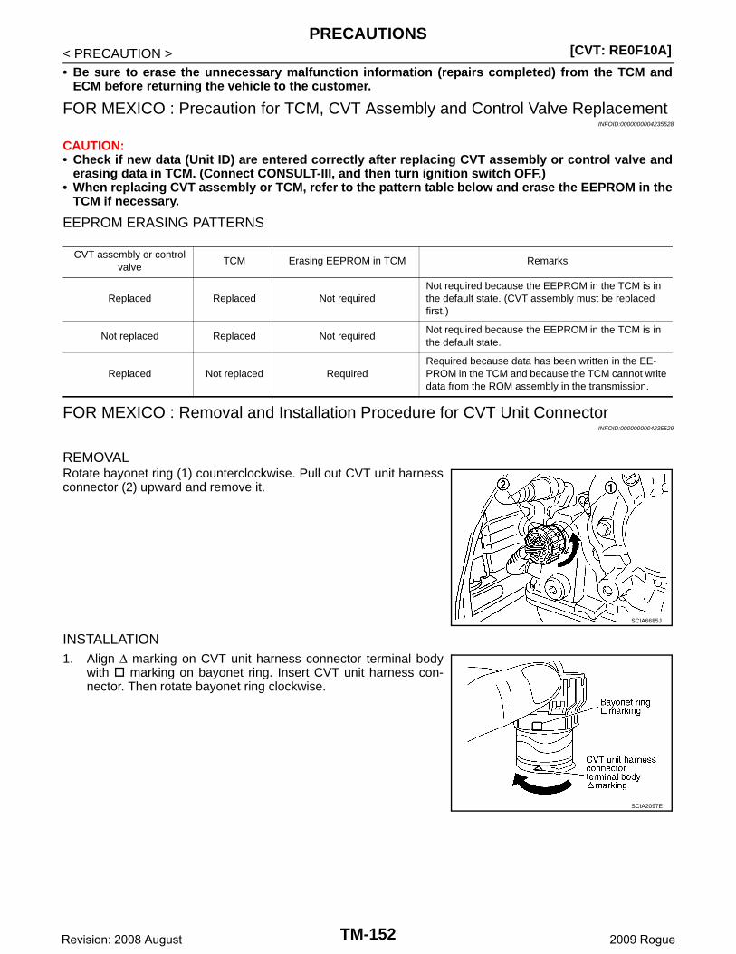
[CVT: RE0F10A]PRECAUTIONS
< PRECAUTION >• Be sure to erase the unnecessary malfunction information (repairs completed) from the TCM and
ECM before returning the vehicle to the customer.
FOR MEXICO : Precaution for TCM, CVT Assembly and Control Valve ReplacementINFOID:0000000004235528
CAUTION:• Check if new data (Unit ID) are entered correctly after replacing CVT assembly or control valve and
erasing data in TCM. (Connect CONSULT-III, and then turn ignition switch OFF.)• When replacing CVT assembly or TCM, refer to the pattern table below and erase the EEPROM in the
TCM if necessary.
EEPROM ERASING PATTERNS
FOR MEXICO : Removal and Installation Procedure for CVT Unit ConnectorINFOID:0000000004235529
REMOVALRotate bayonet ring (1) counterclockwise. Pull out CVT unit harnessconnector (2) upward and remove it.
INSTALLATION1. Align ∆ marking on CVT unit harness connector terminal body
with marking on bayonet ring. Insert CVT unit harness con-nector. Then rotate bayonet ring clockwise.
CVT assembly or control valve
TCM Erasing EEPROM in TCM Remarks
Replaced Replaced Not requiredNot required because the EEPROM in the TCM is in the default state. (CVT assembly must be replaced first.)
Not replaced Replaced Not requiredNot required because the EEPROM in the TCM is in the default state.
Replaced Not replaced RequiredRequired because data has been written in the EE-PROM in the TCM and because the TCM cannot write data from the ROM assembly in the transmission.
SCIA6685J
SCIA2097E
TM-152Revision: 2008 August 2009 Rogue
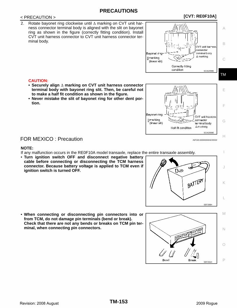
PRECAUTIONS[CVT: RE0F10A]
C
E
F
G
H
I
J
K
L
M
A
B
M
N
O
P
< PRECAUTION >
T
2. Rotate bayonet ring clockwise until ∆ marking on CVT unit har-ness connector terminal body is aligned with the slit on bayonetring as shown in the figure (correctly fitting condition). InstallCVT unit harness connector to CVT unit harness connector ter-minal body.
CAUTION:• Securely align ∆ marking on CVT unit harness connector
terminal body with bayonet ring slit. Then, be careful notto make a half fit condition as shown in the figure.
• Never mistake the slit of bayonet ring for other dent por-tion.
FOR MEXICO : Precaution INFOID:0000000004235530
NOTE:If any malfunction occurs in the RE0F10A model transaxle, replace the entire transaxle assembly.• Turn ignition switch OFF and disconnect negative battery
cable before connecting or disconnecting the TCM harnessconnector. Because battery voltage is applied to TCM even ifignition switch is turned OFF.
• When connecting or disconnecting pin connectors into orfrom TCM, do not damage pin terminals (bend or break).Check that there are not any bends or breaks on TCM pin ter-minal, when connecting pin connectors.
SCIA2098E
SCIA2099E
SEF289H
SEF291H
TM-153Revision: 2008 August 2009 Rogue
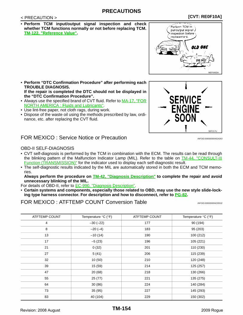
[CVT: RE0F10A]PRECAUTIONS
< PRECAUTION >• Perform TCM input/output signal inspection and check
whether TCM functions normally or not before replacing TCM.TM-122, "Reference Value".
• Perform “DTC Confirmation Procedure” after performing eachTROUBLE DIAGNOSIS.If the repair is completed the DTC should not be displayed inthe “DTC Confirmation Procedure”.
• Always use the specified brand of CVT fluid. Refer to MA-17, "FORNORTH AMERICA : Fluids and Lubricants".
• Use lint-free paper, not cloth rags, during work.• Dispose of the waste oil using the methods prescribed by law, ordi-
nance, etc. after replacing the CVT fluid.
FOR MEXICO : Service Notice or Precaution INFOID:0000000004524263
OBD-II SELF-DIAGNOSIS• CVT self-diagnosis is performed by the TCM in combination with the ECM. The results can be read through
the blinking pattern of the Malfunction Indicator Lamp (MIL). Refer to the table on TM-44, "CONSULT-IIIFunction (TRANSMISSION)" for the indicator used to display each self-diagnostic result.
• The self-diagnostic results indicated by the MIL are automatically stored in both the ECM and TCM memo-ries.Always perform the procedure on TM-42, "Diagnosis Description" to complete the repair and avoidunnecessary blinking of the MIL.
For details of OBD-II, refer to EC-990, "Diagnosis Description".• Certain systems and components, especially those related to OBD, may use the new style slide-lock-
ing type harness connector. For description and how to disconnect, refer to PG-82.
FOR MEXICO : ATFTEMP COUNT Conversion Table INFOID:0000000004235532
MEF040DA
SEF217U
ATFTEMP COUNT Temperature °C (°F) ATFTEMP COUNT Temperature °C (°F)
4 –30 (–22) 177 90 (194)
8 –20 (–4) 183 95 (203)
13 –10 (14) 190 100 (212)
17 –5 (23) 196 105 (221)
21 0 (32) 201 110 (230)
27 5 (41) 206 115 (239)
32 10 (50) 210 120 (248)
39 15 (59) 214 125 (257)
47 20 (68) 218 130 (266)
55 25 (77) 221 135 (275)
64 30 (86) 224 140 (284)
73 35 (95) 227 145 (293)
83 40 (104) 229 150 (302)
TM-154Revision: 2008 August 2009 Rogue
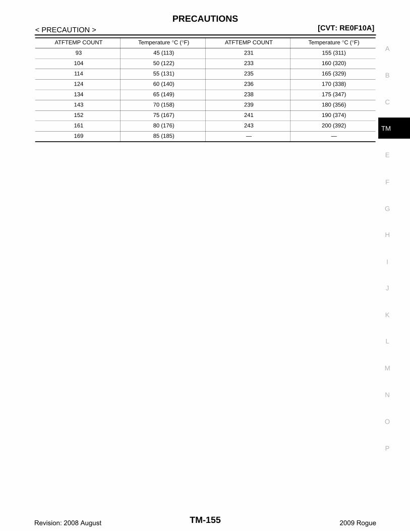
PRECAUTIONS[CVT: RE0F10A]
C
E
F
G
H
I
J
K
L
M
A
B
M
N
O
P
< PRECAUTION >
T
93 45 (113) 231 155 (311)
104 50 (122) 233 160 (320)
114 55 (131) 235 165 (329)
124 60 (140) 236 170 (338)
134 65 (149) 238 175 (347)
143 70 (158) 239 180 (356)
152 75 (167) 241 190 (374)
161 80 (176) 243 200 (392)
169 85 (185) — —
ATFTEMP COUNT Temperature °C (°F) ATFTEMP COUNT Temperature °C (°F)
TM-155Revision: 2008 August 2009 Rogue
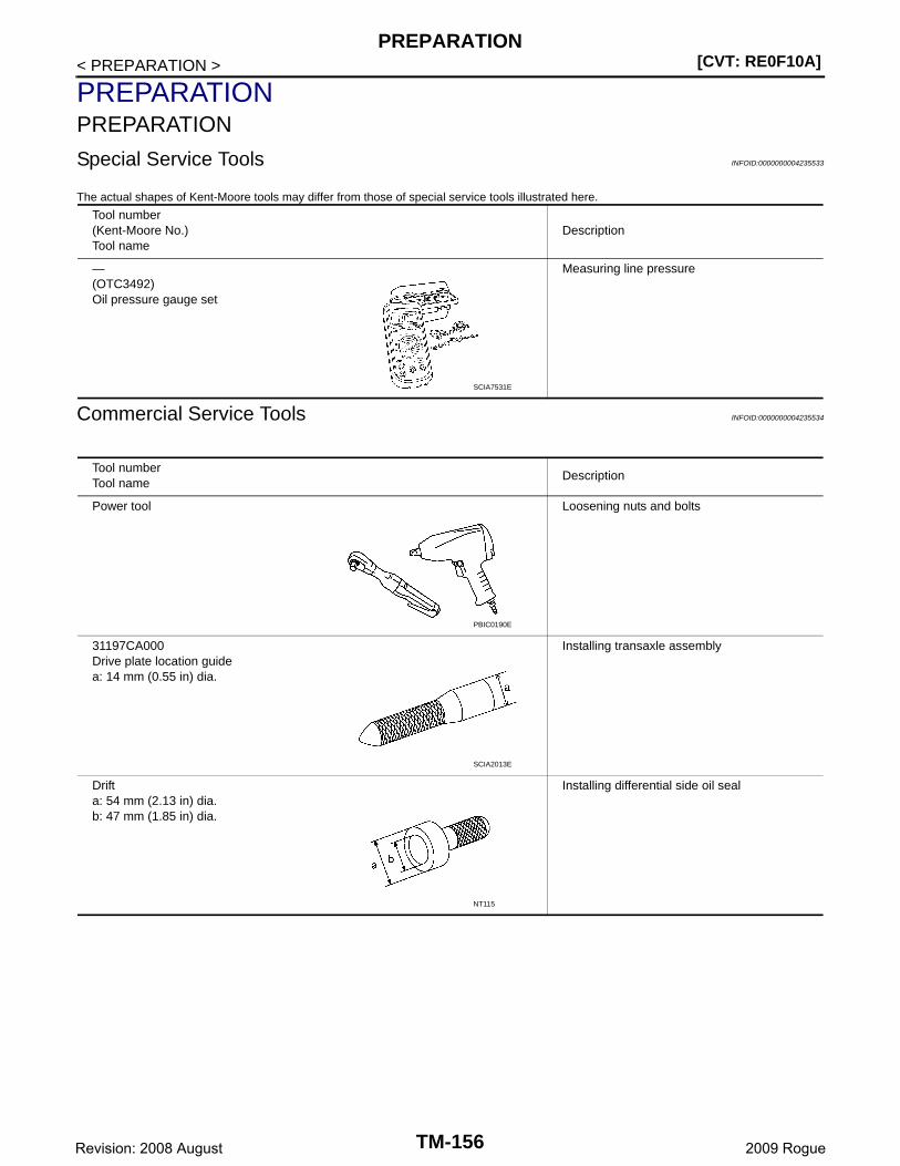
[CVT: RE0F10A]PREPARATION
< PREPARATION >
PREPARATIONPREPARATION
Special Service Tools INFOID:0000000004235533
The actual shapes of Kent-Moore tools may differ from those of special service tools illustrated here.
Commercial Service Tools INFOID:0000000004235534
Tool number(Kent-Moore No.)Tool name
Description
—(OTC3492)Oil pressure gauge set
Measuring line pressure
SCIA7531E
Tool numberTool name
Description
Power tool Loosening nuts and bolts
31197CA000Drive plate location guidea: 14 mm (0.55 in) dia.
Installing transaxle assembly
Drift a: 54 mm (2.13 in) dia.b: 47 mm (1.85 in) dia.
Installing differential side oil seal
PBIC0190E
SCIA2013E
NT115
TM-156Revision: 2008 August 2009 Rogue

PREPARATION[CVT: RE0F10A]
C
E
F
G
H
I
J
K
L
M
A
B
M
N
O
P
< PREPARATION >
T
Drift a: 70 mm (2.76 in) dia.b: 56 mm (2.20 in) dia.
Installing side oil seal (transfer joint)
Drift a: 65 mm (2.56 in) dia.b: 60 mm (2.36 in) dia.
Installing converter housing oil seal
Tool numberTool name
Description
NT115
NT115
TM-157Revision: 2008 August 2009 Rogue

[CVT: RE0F10A]CVT FLUID
< ON-VEHICLE MAINTENANCE >
ON-VEHICLE MAINTENANCECVT FLUID
Inspection INFOID:0000000004235535
CHECKING CVT FLUIDThe fluid level should be checked with the fluid warmed up to 50 to 80°C (122 to 176°F). The fluid level checkprocedure is as follows:1. Check for fluid leakage.2. With the engine warmed up, drive the vehicle in an urban area.
When ambient temperature is 20°C (68°F), it takes about 10minutes for the CVT fluid to warm up to 50 to 80°C (122 to176°F).
3. Park the vehicle on a level surface.4. Apply parking brake firmly.5. With engine at idle, while depressing brake pedal, shift selector
lever throughout the entire shift range.
6. Pull out the CVT fluid level gauge from the CVT fluid chargingpipe after pressing the tab on the CVT fluid level gauge torelease the lock.
7. Wipe fluid off the CVT fluid level gauge. Insert the CVT fluidlevel gauge rotating 180° from the originally installed position,then securely push the CVT fluid level gauge until it meets thetop end of the CVT fluid charging pipe.CAUTION:When wiping away the CVT fluid level gauge, always uselint-free paper, not a cloth rag.
8. Place the selector lever in “P” or “N” and check that the fluidlevel is within the specified range.CAUTION:When reinstalling CVT fluid level gauge, insert it into theCVT fluid charging pipe and rotate it to the original installa-tion position until securely locked.
CVT FLUID CONDITION
SMA146B
SCIA1933E
SCIA1931E
SCIA1932E
TM-158Revision: 2008 August 2009 Rogue
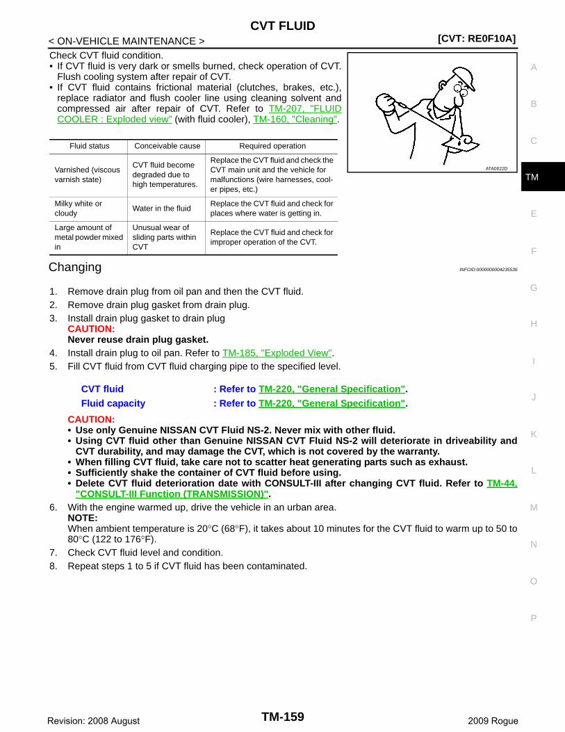
CVT FLUID[CVT: RE0F10A]
C
E
F
G
H
I
J
K
L
M
A
B
M
N
O
P
< ON-VEHICLE MAINTENANCE >
T
Check CVT fluid condition.• If CVT fluid is very dark or smells burned, check operation of CVT.
Flush cooling system after repair of CVT.• If CVT fluid contains frictional material (clutches, brakes, etc.),
replace radiator and flush cooler line using cleaning solvent andcompressed air after repair of CVT. Refer to TM-207, "FLUIDCOOLER : Exploded view" (with fluid cooler), TM-160, "Cleaning".
Changing INFOID:0000000004235536
1. Remove drain plug from oil pan and then the CVT fluid.2. Remove drain plug gasket from drain plug.3. Install drain plug gasket to drain plug
CAUTION:Never reuse drain plug gasket.
4. Install drain plug to oil pan. Refer to TM-185, "Exploded View".5. Fill CVT fluid from CVT fluid charging pipe to the specified level.
CAUTION:• Use only Genuine NISSAN CVT Fluid NS-2. Never mix with other fluid.• Using CVT fluid other than Genuine NISSAN CVT Fluid NS-2 will deteriorate in driveability and
CVT durability, and may damage the CVT, which is not covered by the warranty.• When filling CVT fluid, take care not to scatter heat generating parts such as exhaust.• Sufficiently shake the container of CVT fluid before using.• Delete CVT fluid deterioration date with CONSULT-III after changing CVT fluid. Refer to TM-44,
"CONSULT-III Function (TRANSMISSION)".6. With the engine warmed up, drive the vehicle in an urban area.
NOTE:When ambient temperature is 20°C (68°F), it takes about 10 minutes for the CVT fluid to warm up to 50 to80°C (122 to 176°F).
7. Check CVT fluid level and condition.8. Repeat steps 1 to 5 if CVT fluid has been contaminated.
Fluid status Conceivable cause Required operation
Varnished (viscous varnish state)
CVT fluid become degraded due to high temperatures.
Replace the CVT fluid and check the CVT main unit and the vehicle for malfunctions (wire harnesses, cool-er pipes, etc.)
Milky white or cloudy
Water in the fluidReplace the CVT fluid and check for places where water is getting in.
Large amount of metal powder mixed in
Unusual wear of sliding parts within CVT
Replace the CVT fluid and check for improper operation of the CVT.
ATA0022D
CVT fluid : Refer to TM-220, "General Specification".Fluid capacity : Refer to TM-220, "General Specification".
TM-159Revision: 2008 August 2009 Rogue

[CVT: RE0F10A]CVT FLUID COOLER SYSTEM
< ON-VEHICLE MAINTENANCE >
CVT FLUID COOLER SYSTEM
Cleaning INFOID:0000000004235537
Whenever an automatic transaxle is repaired, overhauled, or replaced, the CVT fluid cooler mounted in theradiator must be inspected and cleaned.Metal debris and friction material, if present, can be trapped or be deposited in the CVT fluid cooler. Thisdebris can contaminate the newly serviced CVT or, in severe cases, can block or restrict the flow of CVT fluid.In either case, malfunction of the newly serviced CVT may occur.Debris, if present, may deposit as CVT fluid enters the cooler inlet. It will be necessary to back flush the coolerthrough the cooler outlet in order to flush out any built up debris.
CVT FLUID COOLER CLEANING PROCEDURE1. Position an oil pan under the transaxle's inlet and outlet cooler hoses.2. Identify the inlet and outlet fluid cooler hoses.3. Disconnect the fluid cooler inlet and outlet rubber hoses from the
steel cooler tubes or bypass valve.NOTE:Replace the cooler hoses if rubber material from the hoseremains on the tube fitting.
4. Allow any CVT fluid that remains in the cooler hoses to drain intothe oil pan.
5. Insert the extension adapter hose of a can of TransmissionCooler Cleaner (Nissan P/N 999MP-AM006) into the cooler out-let hose.CAUTION:• Wear safety glasses and rubber gloves when spraying the
Transmission Cooler Cleaner.• Spray Transmission Cooler Cleaner only with adequate
ventilation.• Avoid contact with eyes and skin.• Never breath vapors or spray mist.
6. Hold the hose and can as high as possible and spray Transmis-sion Cooler Cleaner in a continuous stream into the cooler outlethose until CVT fluid flows out of the cooler inlet hose for 5 seconds.
7. Insert the tip of an air gun into the end of the cooler outlet hose.8. Wrap a shop rag around the air gun tip and end of the cooler
outlet hose.
9. Blow compressed air regulated to 5 to 9 kg/cm2 (70 to 130 psi)through the cooler outlet hose for 10 seconds to force out anyremaining CVT fluid.
10. Repeat steps 5 through 9 three additional times.11. Position an oil pan under the banjo bolts that connect the CVT
fluid cooler steel lines to the transaxle.12. Remove the banjo bolts.13. Flush each steel line from the cooler side back toward the tran-
saxle by spraying Transmission Cooler Cleaner in a continuous stream for 5 seconds.
14. Blow compressed air regulated to 5 to 9 kg/cm2 (70 to 130 psi) through each steel line from the coolerside back toward the transaxle for 10 seconds to force out any remaining CVT fluid.
15. Ensure all debris is removed from the steel cooler lines.16. Ensure all debris is removed from the banjo bolts and fittings.
SCIA4421E
SCIA4422E
SCIA4423E
TM-160Revision: 2008 August 2009 Rogue
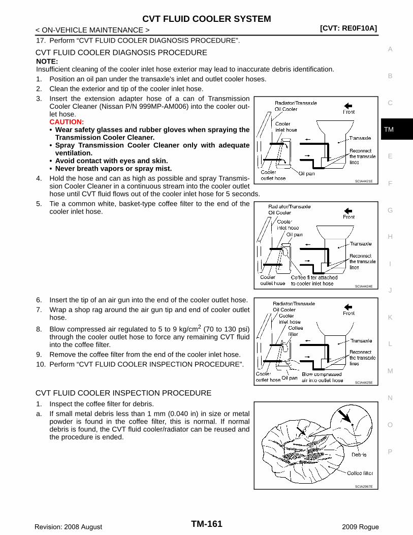
CVT FLUID COOLER SYSTEM[CVT: RE0F10A]
C
E
F
G
H
I
J
K
L
M
A
B
M
N
O
P
< ON-VEHICLE MAINTENANCE >
T
17. Perform “CVT FLUID COOLER DIAGNOSIS PROCEDURE”.
CVT FLUID COOLER DIAGNOSIS PROCEDURENOTE:Insufficient cleaning of the cooler inlet hose exterior may lead to inaccurate debris identification.1. Position an oil pan under the transaxle's inlet and outlet cooler hoses.2. Clean the exterior and tip of the cooler inlet hose.3. Insert the extension adapter hose of a can of Transmission
Cooler Cleaner (Nissan P/N 999MP-AM006) into the cooler out-let hose.CAUTION:• Wear safety glasses and rubber gloves when spraying the
Transmission Cooler Cleaner.• Spray Transmission Cooler Cleaner only with adequate
ventilation.• Avoid contact with eyes and skin.• Never breath vapors or spray mist.
4. Hold the hose and can as high as possible and spray Transmis-sion Cooler Cleaner in a continuous stream into the cooler outlethose until CVT fluid flows out of the cooler inlet hose for 5 seconds.
5. Tie a common white, basket-type coffee filter to the end of thecooler inlet hose.
6. Insert the tip of an air gun into the end of the cooler outlet hose.7. Wrap a shop rag around the air gun tip and end of cooler outlet
hose.
8. Blow compressed air regulated to 5 to 9 kg/cm2 (70 to 130 psi)through the cooler outlet hose to force any remaining CVT fluidinto the coffee filter.
9. Remove the coffee filter from the end of the cooler inlet hose.10. Perform “CVT FLUID COOLER INSPECTION PROCEDURE”.
CVT FLUID COOLER INSPECTION PROCEDURE1. Inspect the coffee filter for debris.a. If small metal debris less than 1 mm (0.040 in) in size or metal
powder is found in the coffee filter, this is normal. If normaldebris is found, the CVT fluid cooler/radiator can be reused andthe procedure is ended.
SCIA4421E
SCIA4424E
SCIA4425E
SCIA2967E
TM-161Revision: 2008 August 2009 Rogue
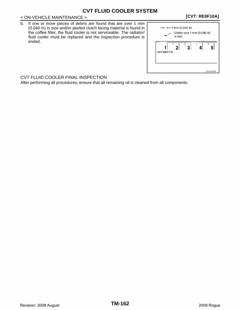
[CVT: RE0F10A]CVT FLUID COOLER SYSTEM
< ON-VEHICLE MAINTENANCE >b. If one or more pieces of debris are found that are over 1 mm
(0.040 in) in size and/or peeled clutch facing material is found inthe coffee filter, the fluid cooler is not serviceable. The radiator/fluid cooler must be replaced and the inspection procedure isended.
CVT FLUID COOLER FINAL INSPECTIONAfter performing all procedures, ensure that all remaining oil is cleaned from all components.
SCIA7031E
TM-162Revision: 2008 August 2009 Rogue
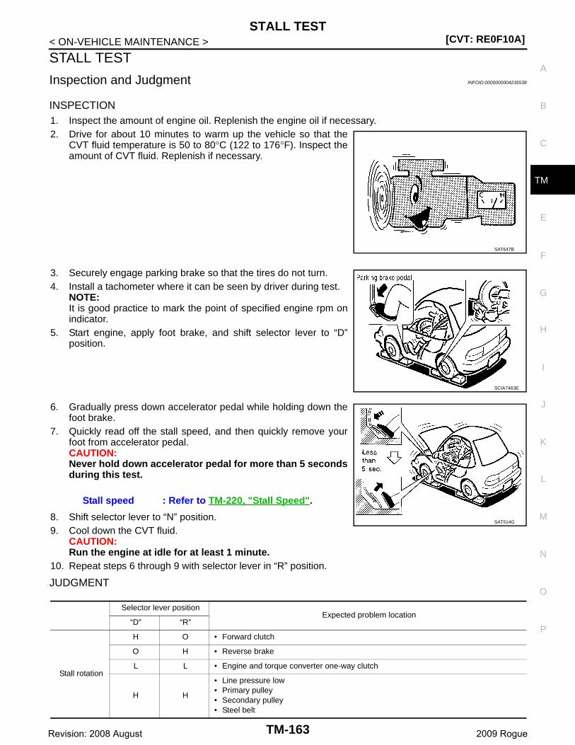
STALL TEST[CVT: RE0F10A]
C
E
F
G
H
I
J
K
L
M
A
B
M
N
O
P
< ON-VEHICLE MAINTENANCE >
T
STALL TEST
Inspection and Judgment INFOID:0000000004235538
INSPECTION1. Inspect the amount of engine oil. Replenish the engine oil if necessary.2. Drive for about 10 minutes to warm up the vehicle so that the
CVT fluid temperature is 50 to 80°C (122 to 176°F). Inspect theamount of CVT fluid. Replenish if necessary.
3. Securely engage parking brake so that the tires do not turn.4. Install a tachometer where it can be seen by driver during test.
NOTE:It is good practice to mark the point of specified engine rpm onindicator.
5. Start engine, apply foot brake, and shift selector lever to “D”position.
6. Gradually press down accelerator pedal while holding down thefoot brake.
7. Quickly read off the stall speed, and then quickly remove yourfoot from accelerator pedal.CAUTION:Never hold down accelerator pedal for more than 5 secondsduring this test.
8. Shift selector lever to “N” position.9. Cool down the CVT fluid.
CAUTION:Run the engine at idle for at least 1 minute.
10. Repeat steps 6 through 9 with selector lever in “R” position.
JUDGMENT
SAT647B
SCIA7463E
Stall speed : Refer to TM-220, "Stall Speed".
SAT514G
Selector lever positionExpected problem location
“D” “R”
Stall rotation
H O • Forward clutch
O H • Reverse brake
L L • Engine and torque converter one-way clutch
H H
• Line pressure low• Primary pulley• Secondary pulley• Steel belt
TM-163Revision: 2008 August 2009 Rogue
[CVT: RE0F10A]STALL TEST
< ON-VEHICLE MAINTENANCE >O: Stall speed within standard value position.
H: Stall speed is higher than standard value.
L: Stall speed is lower than standard value.
TM-164Revision: 2008 August 2009 Rogue

LINE PRESSURE TEST[CVT: RE0F10A]
C
E
F
G
H
I
J
K
L
M
A
B
M
N
O
P
< ON-VEHICLE MAINTENANCE >
T
LINE PRESSURE TEST
Inspection and Judgment INFOID:0000000004235539
INSPECTION
Line Pressure Test Procedure
1. Inspect the amount of engine oil and replenish if necessary.2. Drive the car for about 10 minutes to warm it up so that the CVT fluid reaches in the range of 50 to 80°C
(122 to 176°F). Then inspect the amount of CVT fluid and replenish if necessary.NOTE:The CVT fluid temperature rises in the range of 50 to 80°C (122 to 176°F) during 10 minutes of driv-ing.
3. After warming up transaxle assembly, remove oil pressuredetection plug and install oil pressure gauge [special servicetool: — (OTC3492)].CAUTION:When using oil pressure gauge, be sure to use O-ringattached to oil pressure detection plug.
4. Securely engage parking brake so that the tires do not turn.
5. Start the engine, and then measure the line pressure at both idleand the stall speed.CAUTION:• Keep brake pedal pressed all the way down during mea-
surement.• When measuring the line pressure at the stall speed.
Refer to TM-163, "Inspection and Judgment".
6. Install oil pressure detection plug and tighten to the specifiedtorque below after the measurements are complete.
CAUTION:• Never reuse O-ring.• Apply CVT fluid to O-ring.
JUDGMENT
JPDIA0468GB
SCIA7463E
Line pressure : Refer to TM-220, "Line Pressure".
: 7.5 N·m (0.77 kg-m, 66 in-lb)
SAT493G
TM-165Revision: 2008 August 2009 Rogue

[CVT: RE0F10A]LINE PRESSURE TEST
< ON-VEHICLE MAINTENANCE >
*: Without manual mode
Judgment Possible cause
Idle speed
Low for all positions (“P”, “R”, “N”, “D”, “L”*)
Possible causes include malfunctions in the pressure supply system and low oil pump output.For example• Oil pump wear• Pressure regulator valve or plug sticking or spring fatigue• Oil strainer ⇒ oil pump ⇒ pressure regulator valve passage oil leak• Engine idle speed too low
Only low for a specific position
Possible causes include an oil pressure leak in a passage or device related to the position after the pressure is distributed by the manual valve.
High
Possible causes include a sensor malfunction or malfunction in the line pressure adjustment function.For example• Accelerator pedal position signal malfunction• CVT fluid temperature sensor malfunction• Pressure control solenoid A (line pressure solenoid) malfunction (sticking in OFF state, filter
clog, cut line)• Pressure regulator valve or plug sticking
Stall speed
Line pressure does not rise higher than the line pressure for idle.
Possible causes include a sensor malfunction or malfunction in the pressure adjustment func-tion.For example• Accelerator pedal position signal malfunction• TCM malfunction• Pressure control solenoid A (line pressure solenoid) malfunction (shorting, sticking in ON
state)• Pressure regulator valve or plug sticking
The pressure rises, but does not enter the standard position.
Possible causes include malfunctions in the pressure supply system and malfunction in the pres-sure adjustment function.For example• Accelerator pedal position signal malfunction• Pressure control solenoid A (line pressure solenoid) malfunction (sticking, filter clog)• Pressure regulator valve or plug sticking
Only low for a specific position
Possible causes include an oil pressure leak in a passage or device related to the position after the pressure is distributed by the manual valve.
TM-166Revision: 2008 August 2009 Rogue

ROAD TEST[CVT: RE0F10A]
C
E
F
G
H
I
J
K
L
M
A
B
M
N
O
P
< ON-VEHICLE MAINTENANCE >
T
ROAD TEST
Description INFOID:0000000004235540
DESCRIPTION• The purpose of the test is to determine the overall performance of
CVT and analyze causes of problems.• The road test consists of the following three parts:1. “Check Before Engine Is Started” TM-167.2. “Check at Idle” TM-167.3. “Cruise Test” TM-168.
• Before the road test, familiarize yourself with all test proceduresand items to check.
• Perform tests for all the check items until a malfunction phenome-non is detected. Perform diagnosis for NG items after the comple-tion of road tests.
Check before Engine Is Started INFOID:0000000004235541
1.CHECK OD OFF INDICATOR LAMP
1. Park vehicle on flat surface.2. Shift selector lever to “P” position.3. Turn ignition switch OFF. Wait at least 5 seconds.4. Turn ignition switch ON. (Never start engine.)Has OD OFF indicator lamp been turned ON for about 2 seconds?YES >> 1. Turn ignition switch OFF.
2. Perform self-diagnosis and note NG items. Refer to TM-133, "DTC Index".3. Go to TM-167, "Check at Idle".
NO >> Stop “Road Test”. Refer to TM-134, "Symptom Table".
Check at Idle INFOID:0000000004235542
1.CHECK STARTING THE ENGINE (PART 1)
1. Park vehicle on flat surface.2. Shift selector lever to “P” or “N” position.3. Turn ignition switch OFF.4. Turn ignition switch to “START” position.Is engine started?YES >> GO TO 2.NO >> Stop “Road Test”. Refer to TM-134, "Symptom Table".
2.CHECK STARTING THE ENGINE (PART 2)
Without manual mode1. Turn ignition switch ON.2. Shift selector lever to “D”, “L” or “R” position.3. Turn ignition switch to “START” position.
SAT786A
SAT496G
TM-167Revision: 2008 August 2009 Rogue
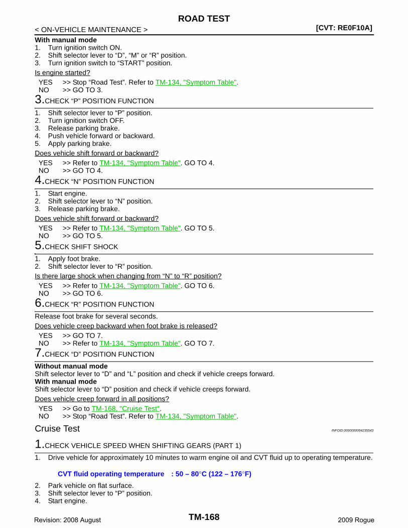
[CVT: RE0F10A]ROAD TEST
< ON-VEHICLE MAINTENANCE >With manual mode1. Turn ignition switch ON.2. Shift selector lever to “D”, “M” or “R” position.3. Turn ignition switch to “START” position.Is engine started?YES >> Stop “Road Test”. Refer to TM-134, "Symptom Table".NO >> GO TO 3.
3.CHECK “P” POSITION FUNCTION
1. Shift selector lever to “P” position.2. Turn ignition switch OFF.3. Release parking brake.4. Push vehicle forward or backward.5. Apply parking brake.Does vehicle shift forward or backward?YES >> Refer to TM-134, "Symptom Table". GO TO 4.NO >> GO TO 4.
4.CHECK “N” POSITION FUNCTION
1. Start engine.2. Shift selector lever to “N” position.3. Release parking brake.Does vehicle shift forward or backward?YES >> Refer to TM-134, "Symptom Table". GO TO 5.NO >> GO TO 5.
5.CHECK SHIFT SHOCK
1. Apply foot brake.2. Shift selector lever to “R” position.Is there large shock when changing from “N” to “R” position?YES >> Refer to TM-134, "Symptom Table". GO TO 6.NO >> GO TO 6.
6.CHECK “R” POSITION FUNCTION
Release foot brake for several seconds.Does vehicle creep backward when foot brake is released?YES >> GO TO 7.NO >> Refer to TM-134, "Symptom Table". GO TO 7.
7.CHECK “D” POSITION FUNCTION
Without manual modeShift selector lever to “D” and “L” position and check if vehicle creeps forward.With manual modeShift selector lever to “D” position and check if vehicle creeps forward.Does vehicle creep forward in all positions?YES >> Go to TM-168, "Cruise Test".NO >> Stop “Road Test”. Refer to TM-134, "Symptom Table".
Cruise Test INFOID:0000000004235543
1.CHECK VEHICLE SPEED WHEN SHIFTING GEARS (PART 1)
1. Drive vehicle for approximately 10 minutes to warm engine oil and CVT fluid up to operating temperature.
2. Park vehicle on flat surface.3. Shift selector lever to “P” position.4. Start engine.
CVT fluid operating temperature : 50 – 80°C (122 – 176°F)
TM-168Revision: 2008 August 2009 Rogue

ROAD TEST[CVT: RE0F10A]
C
E
F
G
H
I
J
K
L
M
A
B
M
N
O
P
< ON-VEHICLE MAINTENANCE >
T
5. Shift selector lever to “D” position.6. Accelerate vehicle at 2/8 throttle opening and check “Vehicle
Speed When Shifting Gears”.
With CONSULT-III- Read vehicle speed and engine speed. Refer to TM-220, "Vehi-
cle Speed When Shifting Gears".Is the inspection result normal?YES >> GO TO 2.NO >> Refer to TM-134, "Symptom Table". GO TO 2.
2.CHECK VEHICLE SPEED WHEN SHIFTING GEARS (PART 2)
1. Park vehicle on flat surface.2. Shift selector lever to “D” position.3. Accelerate vehicle at 8/8 throttle opening and check “Vehicle
Speed When Shifting Gears”.
With CONSULT-III- Read vehicle speed and engine speed. Refer to TM-220, "Vehi-
cle Speed When Shifting Gears".Is the inspection result normal?YES-1 (Without manual mode)>>GO TO 3.YES-2 (With manual mode)>>GO TO 8.NO-1 (Without manual mode)>>Refer to TM-134, "Symptom
Table". GO TO 3.NO-2 (With manual mode)>>Refer to TM-134, "Symptom Table".
GO TO 8.
3.CHECK OVERDRIVE OFF CONDITION (PART 1)
1. Park vehicle on flat surface.2. Push overdrive control switch.3. Accelerate vehicle at 2/8 throttle opening and check “Vehicle
Speed When Shifting Gears”.
With CONSULT-III- Read vehicle speed and engine speed. Refer to TM-220, "Vehi-
cle Speed When Shifting Gears".Is the inspection result normal?YES >> GO TO 4.NO >> Refer to TM-134, "Symptom Table". GO TO 4.
4.CHECK OVERDRIVE OFF CONDITION (PART 2)
1. Park vehicle on flat surface.2. Push overdrive control switch.3. Accelerate vehicle at 8/8 throttle opening and check “Vehicle
Speed When Shifting Gears”.
With CONSULT-III- Read vehicle speed and engine speed. Refer to TM-220, "Vehi-
cle Speed When Shifting Gears".Is the inspection result normal?YES >> GO TO 5.NO >> Refer to TM-134, "Symptom Table". GO TO 5.
SCIA6644E
SCIA4366E
SCIA6644E
SCIA4366E
TM-169Revision: 2008 August 2009 Rogue
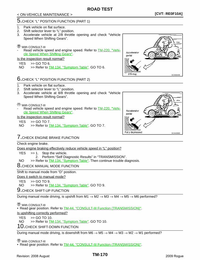
[CVT: RE0F10A]ROAD TEST
< ON-VEHICLE MAINTENANCE >
5.CHECK “L” POSITION FUNCTION (PART 1)
1. Park vehicle on flat surface.2. Shift selector lever to “L” position.3. Accelerate vehicle at 2/8 throttle opening and check “Vehicle
Speed When Shifting Gears”.
With CONSULT-III- Read vehicle speed and engine speed. Refer to TM-220, "Vehi-
cle Speed When Shifting Gears".Is the inspection result normal?YES >> GO TO 6.NO >> Refer to TM-134, "Symptom Table". GO TO 6.
6.CHECK “L” POSITION FUNCTION (PART 2)
1. Park vehicle on flat surface.2. Shift selector lever to “L” position.3. Accelerate vehicle at 8/8 throttle opening and check “Vehicle
Speed When Shifting Gears”.
With CONSULT-III- Read vehicle speed and engine speed. Refer to TM-220, "Vehi-
cle Speed When Shifting Gears".Is the inspection result normal?YES >> GO TO 7.NO >> Refer to TM-134, "Symptom Table". GO TO 7.
7.CHECK ENGINE BRAKE FUNCTION
Check engine brake.Does engine braking effectively reduce vehicle speed in “L” position?YES >> 1. Stop the vehicle.
2. Perform “Self Diagnostic Results” in “TRANSMISSION”.NO >> Refer to TM-134, "Symptom Table". Then continue trouble diagnosis.
8.CHECK MANUAL MODE FUNCTION
Shift to manual mode from “D” position.Does it switch to manual mode?YES >> GO TO 9.NO >> Refer to TM-134, "Symptom Table". GO TO 9.
9.CHECK SHIFT-UP FUNCTION
During manual mode driving, is upshift from M1 → M2 → M3 → M4 → M5 → M6 performed?
With CONSULT-III• Read gear position. Refer to TM-44, "CONSULT-III Function (TRANSMISSION)".Is upshifting correctly performed?YES >> GO TO 10.NO >> Refer to TM-134, "Symptom Table". GO TO 10.
10.CHECK SHIFT-DOWN FUNCTION
During manual mode driving, is downshift from M6 → M5 → M4 → M3 → M2 → M1 performed?
With CONSULT-III• Read gear position. Refer to TM-44, "CONSULT-III Function (TRANSMISSION)".
SCIA6644E
SCIA4366E
TM-170Revision: 2008 August 2009 Rogue
ROAD TEST[CVT: RE0F10A]
C
E
F
G
H
I
J
K
L
M
A
B
M
N
O
P
< ON-VEHICLE MAINTENANCE >
T
Is downshifting correctly performed?YES >> GO TO 11.NO >> Refer to TM-134, "Symptom Table". GO TO 11.
11.CHECK ENGINE BRAKE FUNCTION
Check engine brake.Does engine braking effectively reduce vehicle speed in M1 position?YES >> 1. Stop the vehicle.
2. Perform “Self Diagnostic Results” in “TRANSMISSION”.NO >> Refer to TM-134, "Symptom Table". Then continue trouble diagnosis.
TM-171Revision: 2008 August 2009 Rogue
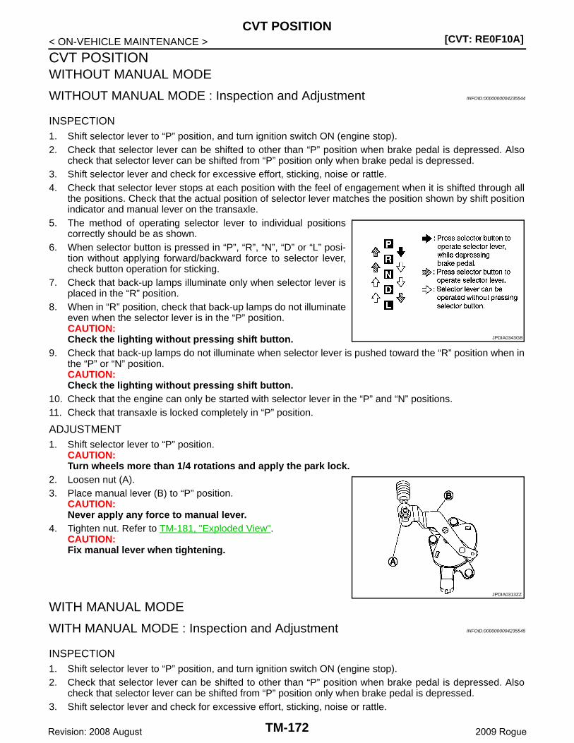
[CVT: RE0F10A]CVT POSITION
< ON-VEHICLE MAINTENANCE >
CVT POSITIONWITHOUT MANUAL MODE
WITHOUT MANUAL MODE : Inspection and Adjustment INFOID:0000000004235544
INSPECTION1. Shift selector lever to “P” position, and turn ignition switch ON (engine stop).2. Check that selector lever can be shifted to other than “P” position when brake pedal is depressed. Also
check that selector lever can be shifted from “P” position only when brake pedal is depressed.3. Shift selector lever and check for excessive effort, sticking, noise or rattle.4. Check that selector lever stops at each position with the feel of engagement when it is shifted through all
the positions. Check that the actual position of selector lever matches the position shown by shift positionindicator and manual lever on the transaxle.
5. The method of operating selector lever to individual positionscorrectly should be as shown.
6. When selector button is pressed in “P”, “R”, “N”, “D” or “L” posi-tion without applying forward/backward force to selector lever,check button operation for sticking.
7. Check that back-up lamps illuminate only when selector lever isplaced in the “R” position.
8. When in “R” position, check that back-up lamps do not illuminateeven when the selector lever is in the “P” position.CAUTION:Check the lighting without pressing shift button.
9. Check that back-up lamps do not illuminate when selector lever is pushed toward the “R” position when inthe “P” or “N” position.CAUTION:Check the lighting without pressing shift button.
10. Check that the engine can only be started with selector lever in the “P” and “N” positions.11. Check that transaxle is locked completely in “P” position.
ADJUSTMENT1. Shift selector lever to “P” position.
CAUTION:Turn wheels more than 1/4 rotations and apply the park lock.
2. Loosen nut (A).3. Place manual lever (B) to “P” position.
CAUTION:Never apply any force to manual lever.
4. Tighten nut. Refer to TM-181, "Exploded View".CAUTION:Fix manual lever when tightening.
WITH MANUAL MODE
WITH MANUAL MODE : Inspection and Adjustment INFOID:0000000004235545
INSPECTION1. Shift selector lever to “P” position, and turn ignition switch ON (engine stop).2. Check that selector lever can be shifted to other than “P” position when brake pedal is depressed. Also
check that selector lever can be shifted from “P” position only when brake pedal is depressed.3. Shift selector lever and check for excessive effort, sticking, noise or rattle.
JPDIA0343GB
JPDIA0313ZZ
TM-172Revision: 2008 August 2009 Rogue
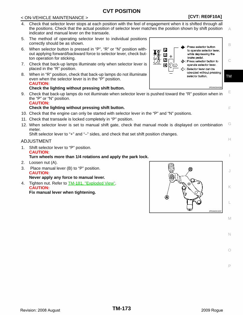
CVT POSITION[CVT: RE0F10A]
C
E
F
G
H
I
J
K
L
M
A
B
M
N
O
P
< ON-VEHICLE MAINTENANCE >
T
4. Check that selector lever stops at each position with the feel of engagement when it is shifted through allthe positions. Check that the actual position of selector lever matches the position shown by shift positionindicator and manual lever on the transaxle.
5. The method of operating selector lever to individual positionscorrectly should be as shown.
6. When selector button is pressed in “P”, “R” or “N” position with-out applying forward/backward force to selector lever, check but-ton operation for sticking.
7. Check that back-up lamps illuminate only when selector lever isplaced in the “R” position.
8. When in “R” position, check that back-up lamps do not illuminateeven when the selector lever is in the “P” position.CAUTION:Check the lighting without pressing shift button.
9. Check that back-up lamps do not illuminate when selector lever is pushed toward the “R” position when inthe “P” or “N” position.CAUTION:Check the lighting without pressing shift button.
10. Check that the engine can only be started with selector lever in the “P” and “N” positions.11. Check that transaxle is locked completely in “P” position.12. When selector lever is set to manual shift gate, check that manual mode is displayed on combination
meter.Shift selector lever to “+” and “–” sides, and check that set shift position changes.
ADJUSTMENT1. Shift selector lever to “P” position.
CAUTION:Turn wheels more than 1/4 rotations and apply the park lock.
2. Loosen nut (A).3. Place manual lever (B) to “P” position.
CAUTION:Never apply any force to manual lever.
4. Tighten nut. Refer to TM-181, "Exploded View".CAUTION:Fix manual lever when tightening.
JPDIA0344GB
JPDIA0313ZZ
TM-173Revision: 2008 August 2009 Rogue
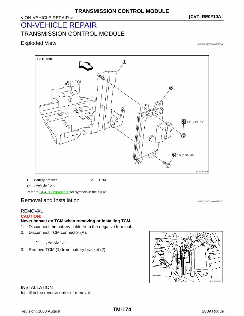
[CVT: RE0F10A]TRANSMISSION CONTROL MODULE
< ON-VEHICLE REPAIR >
ON-VEHICLE REPAIRTRANSMISSION CONTROL MODULE
Exploded View INFOID:0000000004235546
Removal and Installation INFOID:0000000004235547
REMOVALCAUTION:Never impact on TCM when removing or installing TCM.1. Disconnect the battery cable from the negative terminal.2. Disconnect TCM connector (A).
3. Remove TCM (1) from battery bracket (2).
INSTALLATIONInstall in the reverse order of removal.
1. Battery bracket 2. TCM
: Vehicle front
Refer to GI-4, "Components" for symbols in the figure.
JPDIA0413GB
: Vehicle front
JPDIA0414ZZ
TM-174Revision: 2008 August 2009 Rogue
TRANSMISSION CONTROL MODULE[CVT: RE0F10A]
C
E
F
G
H
I
J
K
L
M
A
B
M
N
O
P
< ON-VEHICLE REPAIR >
T
Adjustment INFOID:0000000004235548
ADJUSTMENT AFTER INSTALLATIONAfter TCM is replaced. Refer to TM-9, "ADDITIONAL SERVICE WHEN REPLACING CONTROL UNIT : Ser-vice After Replacing TCM, Transaxle Assembly and Control Valve".
TM-175Revision: 2008 August 2009 Rogue
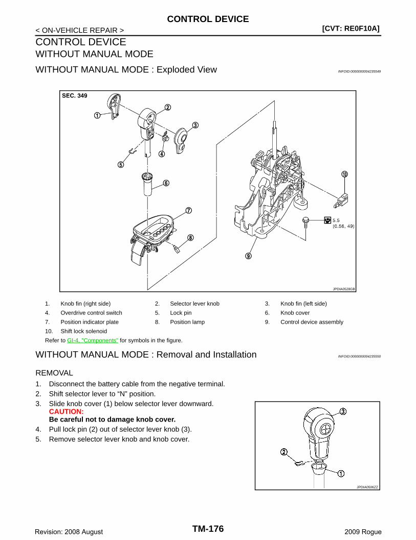
[CVT: RE0F10A]CONTROL DEVICE
< ON-VEHICLE REPAIR >
CONTROL DEVICEWITHOUT MANUAL MODE
WITHOUT MANUAL MODE : Exploded View INFOID:0000000004235549
WITHOUT MANUAL MODE : Removal and Installation INFOID:0000000004235550
REMOVAL1. Disconnect the battery cable from the negative terminal.2. Shift selector lever to “N” position.3. Slide knob cover (1) below selector lever downward.
CAUTION:Be careful not to damage knob cover.
4. Pull lock pin (2) out of selector lever knob (3).5. Remove selector lever knob and knob cover.
1. Knob fin (right side) 2. Selector lever knob 3. Knob fin (left side)
4. Overdrive control switch 5. Lock pin 6. Knob cover
7. Position indicator plate 8. Position lamp 9. Control device assembly
10. Shift lock solenoid
Refer to GI-4, "Components" for symbols in the figure.
JPDIA0528GB
JPDIA0506ZZ
TM-176Revision: 2008 August 2009 Rogue

CONTROL DEVICE[CVT: RE0F10A]
C
E
F
G
H
I
J
K
L
M
A
B
M
N
O
P
< ON-VEHICLE REPAIR >
T
6. Remove knob fin (1) using a flat-bladed screwdriver (A).CAUTION:Be careful not to damage selector lever knob.
7. Remove overdrive control switch (2).8. Remove center console assembly. Refer to IP-20, "Exploded
View".
9. Disconnect shift lock solenoid connector (A).10. Remove shift lock solenoid (1) using a feeler gauge (B).
11. Disconnect control device connector (A).12. Shift selector lever to “P” position.13. Remove key interlock cable (1) from control device assembly.
Refer to TM-183, "Exploded View".14. Remove control cable (2) from control device assembly. Refer to
TM-181, "Exploded View".15. Remove control device assembly.
16. Remove position lamp.
17. Unhook ( ) position indicator plate (1) for removal.
JPDIA0435ZZ
JPDIA0364ZZ
: Bolt
A : Driver side
B : Passenger side
JPDIA0382ZZ
JPDIA0316ZZ
TM-177Revision: 2008 August 2009 Rogue
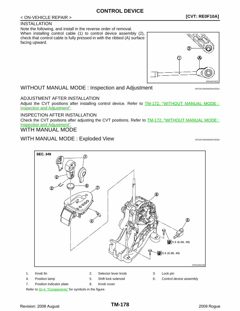
[CVT: RE0F10A]CONTROL DEVICE
< ON-VEHICLE REPAIR >
INSTALLATIONNote the following, and install in the reverse order of removal.When installing control cable (1) to control device assembly (2),check that control cable is fully pressed in with the ribbed (A) surfacefacing upward.
WITHOUT MANUAL MODE : Inspection and Adjustment INFOID:0000000004235551
ADJUSTMENT AFTER INSTALLATIONAdjust the CVT positions after installing control device. Refer to TM-172, "WITHOUT MANUAL MODE :Inspection and Adjustment".
INSPECTION AFTER INSTALLATIONCheck the CVT positions after adjusting the CVT positions. Refer to TM-172, "WITHOUT MANUAL MODE :Inspection and Adjustment".WITH MANUAL MODE
WITH MANUAL MODE : Exploded View INFOID:0000000004235552
JPDIA0078ZZ
1. Knob fin 2. Selector lever knob 3. Lock pin
4. Position lamp 5. Shift lock solenoid 6. Control device assembly
7. Position indicator plate 8. Knob cover
Refer to GI-4, "Components" for symbols in the figure.
JPDIA0462GB
TM-178Revision: 2008 August 2009 Rogue
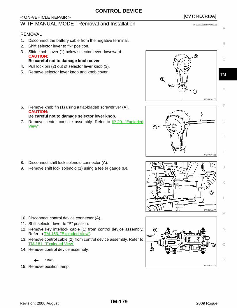
CONTROL DEVICE[CVT: RE0F10A]
C
E
F
G
H
I
J
K
L
M
A
B
M
N
O
P
< ON-VEHICLE REPAIR >
T
WITH MANUAL MODE : Removal and Installation INFOID:0000000004235553
REMOVAL1. Disconnect the battery cable from the negative terminal.2. Shift selector lever to “N” position.3. Slide knob cover (1) below selector lever downward.
CAUTION:Be careful not to damage knob cover.
4. Pull lock pin (2) out of selector lever knob (3).5. Remove selector lever knob and knob cover.
6. Remove knob fin (1) using a flat-bladed screwdriver (A).CAUTION:Be careful not to damage selector lever knob.
7. Remove center console assembly. Refer to IP-20, "ExplodedView".
8. Disconnect shift lock solenoid connector (A).9. Remove shift lock solenoid (1) using a feeler gauge (B).
10. Disconnect control device connector (A).11. Shift selector lever to “P” position. 12. Remove key interlock cable (1) from control device assembly.
Refer to TM-183, "Exploded View".13. Remove control cable (2) from control device assembly. Refer to
TM-181, "Exploded View".14. Remove control device assembly.
15. Remove position lamp.
JPDIA0342ZZ
JPDIA0363ZZ
JPDIA0364ZZ
: Bolt
JPDIA0382ZZ
TM-179Revision: 2008 August 2009 Rogue

[CVT: RE0F10A]CONTROL DEVICE
< ON-VEHICLE REPAIR >
16. Unhook ( ) position indicator plate (1) for removal.
INSTALLATIONNote the following, and install in the reverse order of removal.When installing control cable (1) to control device assembly (2),check that control cable is fully pressed in with the ribbed (A) surfacefacing upward.
WITH MANUAL MODE : Inspection and Adjustment INFOID:0000000004235554
ADJUSTMENT AFTER INSTALLATIONAdjust the CVT positions after installing control device. Refer to TM-172, "WITH MANUAL MODE : Inspectionand Adjustment".
INSPECTION AFTER INSTALLATIONCheck the CVT positions after adjusting the CVT positions. Refer to TM-172, "WITH MANUAL MODE :Inspection and Adjustment".
A : Driver side
B : Passenger side
JPDIA0316ZZ
JPDIA0078ZZ
TM-180Revision: 2008 August 2009 Rogue
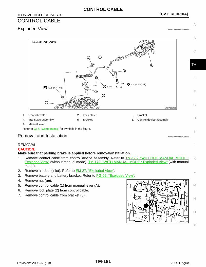
CONTROL CABLE[CVT: RE0F10A]
C
E
F
G
H
I
J
K
L
M
A
B
M
N
O
P
< ON-VEHICLE REPAIR >
T
CONTROL CABLE
Exploded View INFOID:0000000004235555
Removal and Installation INFOID:0000000004235556
REMOVALCAUTION:Make sure that parking brake is applied before removal/installation.1. Remove control cable from control device assembly. Refer to TM-176, "WITHOUT MANUAL MODE :
Exploded View" (without manual mode), TM-178, "WITH MANUAL MODE : Exploded View" (with manualmode).
2. Remove air duct (inlet). Refer to EM-27, "Exploded View".3. Remove battery and battery bracket. Refer to PG-92, "Exploded View".4. Remove nut ( ).5. Remove control cable (1) from manual lever (A).6. Remove lock plate (2) from control cable.7. Remove control cable from bracket (3).
1. Control cable 2. Lock plate 3. Bracket
4. Transaxle assembly 5. Bracket 6. Control device assembly
A. Manual lever
Refer to GI-4, "Components" for symbols in the figure.
JPDIA0354GB
JPDIA0365ZZ
TM-181Revision: 2008 August 2009 Rogue

[CVT: RE0F10A]CONTROL CABLE
< ON-VEHICLE REPAIR >8. Remove control cable (1) from bracket (2).
9. Remove the control cable from the vehicle.
INSTALLATIONNote the following, and install in the reverse order of removal.When installing control cable (1) to control device assembly (2),make sure that control cable is fully pressed in with the ribbed (A)surface facing upward.
Inspection and Adjustment INFOID:0000000004235557
ADJUSTMENT AFTER INSTALLATIONAdjust the CVT positions after installing control cable. Refer to TM-172, "WITHOUT MANUAL MODE : Inspec-tion and Adjustment" (without manual mode), TM-172, "WITH MANUAL MODE : Inspection and Adjustment"(with manual mode).
INSPECTION AFTER INSTALLATIONCheck the CVT positions after adjusting the CVT positions. Refer to TM-172, "WITHOUT MANUAL MODE :Inspection and Adjustment" (without manual mode), TM-172, "WITH MANUAL MODE : Inspection and Adjust-ment" (with manual mode).
: Vehicle front
JPDIA0107ZZ
JPDIA0078ZZ
TM-182Revision: 2008 August 2009 Rogue
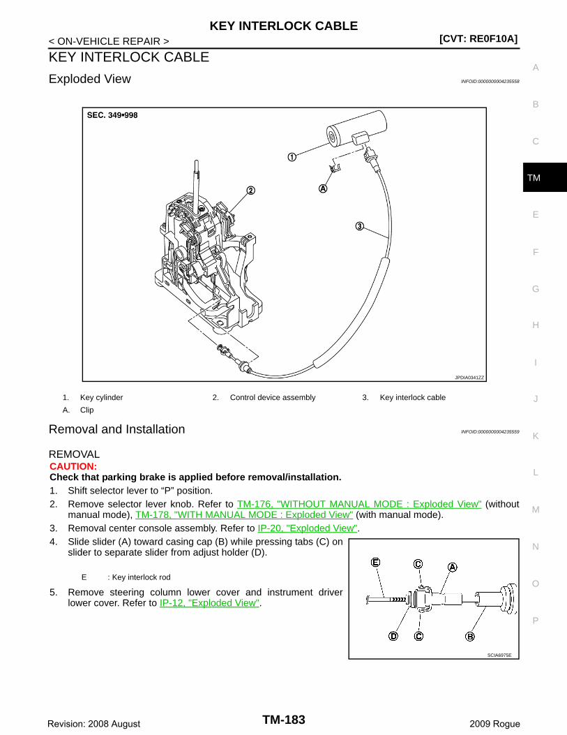
KEY INTERLOCK CABLE[CVT: RE0F10A]
C
E
F
G
H
I
J
K
L
M
A
B
M
N
O
P
< ON-VEHICLE REPAIR >
T
KEY INTERLOCK CABLE
Exploded View INFOID:0000000004235558
Removal and Installation INFOID:0000000004235559
REMOVALCAUTION:Check that parking brake is applied before removal/installation.1. Shift selector lever to “P” position.2. Remove selector lever knob. Refer to TM-176, "WITHOUT MANUAL MODE : Exploded View" (without
manual mode), TM-178, "WITH MANUAL MODE : Exploded View" (with manual mode).3. Removal center console assembly. Refer to IP-20, "Exploded View". 4. Slide slider (A) toward casing cap (B) while pressing tabs (C) on
slider to separate slider from adjust holder (D).
5. Remove steering column lower cover and instrument driverlower cover. Refer to IP-12, "Exploded View".
1. Key cylinder 2. Control device assembly 3. Key interlock cable
A. Clip
JPDIA0341ZZ
E : Key interlock rod
SCIA6975E
TM-183Revision: 2008 August 2009 Rogue
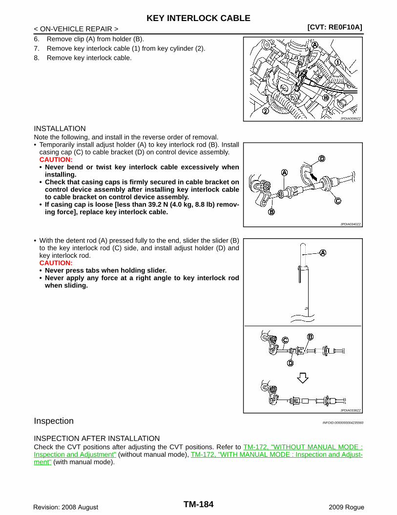
[CVT: RE0F10A]KEY INTERLOCK CABLE
< ON-VEHICLE REPAIR >6. Remove clip (A) from holder (B).7. Remove key interlock cable (1) from key cylinder (2).8. Remove key interlock cable.
INSTALLATIONNote the following, and install in the reverse order of removal.• Temporarily install adjust holder (A) to key interlock rod (B). Install
casing cap (C) to cable bracket (D) on control device assembly.CAUTION:• Never bend or twist key interlock cable excessively when
installing.• Check that casing caps is firmly secured in cable bracket on
control device assembly after installing key interlock cableto cable bracket on control device assembly.
• If casing cap is loose [less than 39.2 N (4.0 kg, 8.8 lb) remov-ing force], replace key interlock cable.
• With the detent rod (A) pressed fully to the end, slider the slider (B)to the key interlock rod (C) side, and install adjust holder (D) andkey interlock rod.CAUTION:• Never press tabs when holding slider.• Never apply any force at a right angle to key interlock rod
when sliding.
Inspection INFOID:0000000004235560
INSPECTION AFTER INSTALLATIONCheck the CVT positions after adjusting the CVT positions. Refer to TM-172, "WITHOUT MANUAL MODE :Inspection and Adjustment" (without manual mode), TM-172, "WITH MANUAL MODE : Inspection and Adjust-ment" (with manual mode).
JPDIA0099ZZ
JPDIA0340ZZ
JPDIA0338ZZ
TM-184Revision: 2008 August 2009 Rogue
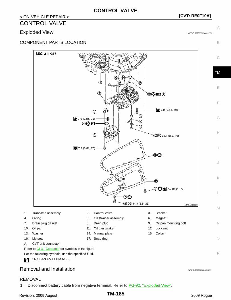
CONTROL VALVE[CVT: RE0F10A]
C
E
F
G
H
I
J
K
L
M
A
B
M
N
O
P
< ON-VEHICLE REPAIR >
T
CONTROL VALVE
Exploded View INFOID:0000000004469773
COMPONENT PARTS LOCATION
Removal and Installation INFOID:0000000004525611
REMOVAL1. Disconnect battery cable from negative terminal. Refer to PG-92, "Exploded View".
1. Transaxle assembly 2. Control valve 3. Bracket
4. O-ring 5. Oil strainer assembly 6. Magnet
7. Drain plug gasket 8. Drain plug 9. Oil pan mounting bolt
10. Oil pan 11. Oil pan gasket 12. Lock nut
13. Washer 14. Manual plate 15. Collar
16. Lip seal 17. Snap ring
A. CVT unit connector
Refer to GI-3, "Contents" for symbols in the figure.
For the following symbols, use the specified fluid.
: NISSAN CVT Fluid NS-2
JPDIA0666GB
TM-185Revision: 2008 August 2009 Rogue

[CVT: RE0F10A]CONTROL VALVE
< ON-VEHICLE REPAIR >2. Remove drain plug from oil pan and then drain the CVT fluid.3. Remove drain plug gasket.4. Disconnect the CVT unit connector. Refer to TM-147, "FOR USA AND CANADA : Removal and Installa-
tion Procedure for CVT Unit Connector" [for California, USA (federal) and Canada], TM-152, "FOR MEX-ICO : Removal and Installation Procedure for CVT Unit Connector" (for Mexico).
5. Remove the snap ring (1) from the CVT unit connector (A).
6. Press the CVT unit connector (A) into the transaxle case.CAUTION:Never damage the CVT unit connector.NOTE:Clean around the connector to prevent foreign materials fromentering into the transaxle case.
7. Remove the oil pan mounting bolts, and then remove the oil pan and oil pan gasket.8. Remove the magnets from the oil pan.9. Remove the lock nut (1) and washer (2), and then remove the
manual plate (3).
10. Remove the collar (4) from the manual shaft (A).CAUTION:Never drop the collar.
11. Disconnect the connectors (A) and (B).
JPDIA0654ZZ
JPDIA0720ZZ
: Vehicle front
JPDIA0655ZZ
: Clip
: Vehicle front
JPDIA0656ZZ
TM-186Revision: 2008 August 2009 Rogue
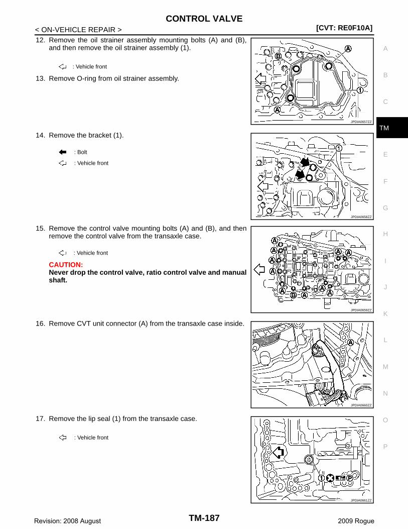
CONTROL VALVE[CVT: RE0F10A]
C
E
F
G
H
I
J
K
L
M
A
B
M
N
O
P
< ON-VEHICLE REPAIR >
T
12. Remove the oil strainer assembly mounting bolts (A) and (B),and then remove the oil strainer assembly (1).
13. Remove O-ring from oil strainer assembly.
14. Remove the bracket (1).
15. Remove the control valve mounting bolts (A) and (B), and thenremove the control valve from the transaxle case.
CAUTION:Never drop the control valve, ratio control valve and manualshaft.
16. Remove CVT unit connector (A) from the transaxle case inside.
17. Remove the lip seal (1) from the transaxle case.
: Vehicle front
JPDIA0657ZZ
: Bolt
: Vehicle front
JPDIA0658ZZ
: Vehicle front
JPDIA0659ZZ
JPDIA0660ZZ
: Vehicle front
JPDIA0661ZZ
TM-187Revision: 2008 August 2009 Rogue
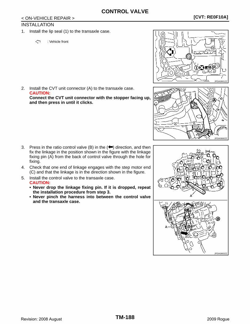
[CVT: RE0F10A]CONTROL VALVE
< ON-VEHICLE REPAIR >
INSTALLATION1. Install the lip seal (1) to the transaxle case.
2. Install the CVT unit connector (A) to the transaxle case.CAUTION:Connect the CVT unit connector with the stopper facing up,and then press in until it clicks.
3. Press in the ratio control valve (B) in the ( ) direction, and thenfix the linkage in the position shown in the figure with the linkagefixing pin (A) from the back of control valve through the hole forfixing.
4. Check that one end of linkage engages with the step motor end(C) and that the linkage is in the direction shown in the figure.
5. Install the control valve to the transaxle case.CAUTION:• Never drop the linkage fixing pin. If it is dropped, repeat
the installation procedure from step 3.• Never pinch the harness into between the control valve
and the transaxle case.
: Vehicle front
JPDIA0661ZZ
JPDIA0660ZZ
JPDIA0663ZZ
TM-188Revision: 2008 August 2009 Rogue
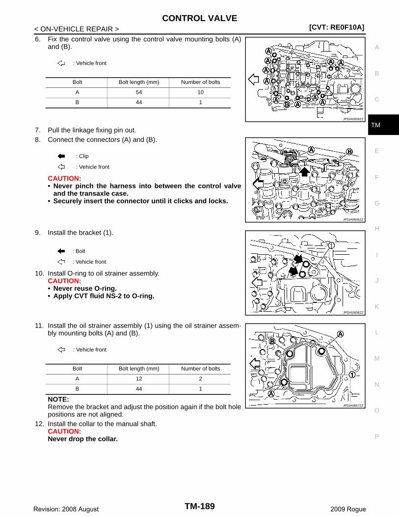
CONTROL VALVE[CVT: RE0F10A]
C
E
F
G
H
I
J
K
L
M
A
B
M
N
O
P
< ON-VEHICLE REPAIR >
T
6. Fix the control valve using the control valve mounting bolts (A)and (B).
7. Pull the linkage fixing pin out.8. Connect the connectors (A) and (B).
CAUTION:• Never pinch the harness into between the control valve
and the transaxle case.• Securely insert the connector until it clicks and locks.
9. Install the bracket (1).
10. Install O-ring to oil strainer assembly.CAUTION:• Never reuse O-ring.• Apply CVT fluid NS-2 to O-ring.
11. Install the oil strainer assembly (1) using the oil strainer assem-bly mounting bolts (A) and (B).
NOTE:Remove the bracket and adjust the position again if the bolt holepositions are not aligned.
12. Install the collar to the manual shaft.CAUTION:Never drop the collar.
: Vehicle front
Bolt Bolt length (mm) Number of bolts
A 54 10
B 44 1
JPDIA0659ZZ
: Clip
: Vehicle front
JPDIA0656ZZ
: Bolt
: Vehicle front
JPDIA0658ZZ
: Vehicle front
Bolt Bolt length (mm) Number of bolts
A 12 2
B 44 1
JPDIA0657ZZ
TM-189Revision: 2008 August 2009 Rogue
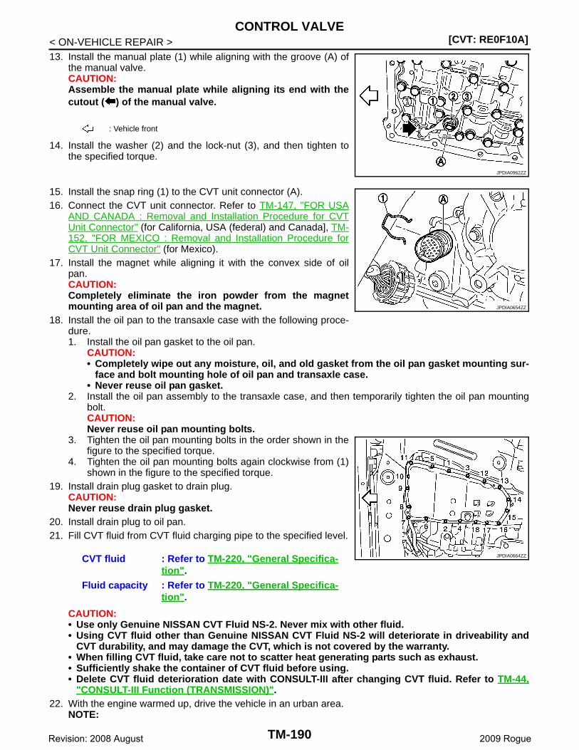
[CVT: RE0F10A]CONTROL VALVE
< ON-VEHICLE REPAIR >13. Install the manual plate (1) while aligning with the groove (A) of
the manual valve.CAUTION:Assemble the manual plate while aligning its end with thecutout ( ) of the manual valve.
14. Install the washer (2) and the lock-nut (3), and then tighten tothe specified torque.
15. Install the snap ring (1) to the CVT unit connector (A).16. Connect the CVT unit connector. Refer to TM-147, "FOR USA
AND CANADA : Removal and Installation Procedure for CVTUnit Connector" (for California, USA (federal) and Canada], TM-152, "FOR MEXICO : Removal and Installation Procedure forCVT Unit Connector" (for Mexico).
17. Install the magnet while aligning it with the convex side of oilpan.CAUTION:Completely eliminate the iron powder from the magnetmounting area of oil pan and the magnet.
18. Install the oil pan to the transaxle case with the following proce-dure.1. Install the oil pan gasket to the oil pan.
CAUTION:• Completely wipe out any moisture, oil, and old gasket from the oil pan gasket mounting sur-
face and bolt mounting hole of oil pan and transaxle case.• Never reuse oil pan gasket.
2. Install the oil pan assembly to the transaxle case, and then temporarily tighten the oil pan mountingbolt.CAUTION:Never reuse oil pan mounting bolts.
3. Tighten the oil pan mounting bolts in the order shown in thefigure to the specified torque.
4. Tighten the oil pan mounting bolts again clockwise from (1)shown in the figure to the specified torque.
19. Install drain plug gasket to drain plug.CAUTION:Never reuse drain plug gasket.
20. Install drain plug to oil pan.21. Fill CVT fluid from CVT fluid charging pipe to the specified level.
CAUTION:• Use only Genuine NISSAN CVT Fluid NS-2. Never mix with other fluid.• Using CVT fluid other than Genuine NISSAN CVT Fluid NS-2 will deteriorate in driveability and
CVT durability, and may damage the CVT, which is not covered by the warranty.• When filling CVT fluid, take care not to scatter heat generating parts such as exhaust.• Sufficiently shake the container of CVT fluid before using.• Delete CVT fluid deterioration date with CONSULT-III after changing CVT fluid. Refer to TM-44,
"CONSULT-III Function (TRANSMISSION)".22. With the engine warmed up, drive the vehicle in an urban area.
NOTE:
: Vehicle front
JPDIA0962ZZ
CVT fluid : Refer to TM-220, "General Specifica-tion".
Fluid capacity : Refer to TM-220, "General Specifica-tion".
JPDIA0654ZZ
JPDIA0664ZZ
TM-190Revision: 2008 August 2009 Rogue

CONTROL VALVE[CVT: RE0F10A]
C
E
F
G
H
I
J
K
L
M
A
B
M
N
O
P
< ON-VEHICLE REPAIR >
T
When ambient temperature is 20°C (68°F), it takes about 10 minutes for the CVT fluid to warm up to 50to80°C (122 to 176°F).
23. Check CVT fluid level and condition. Refer to TM-158, "Inspection".24. Connect battery cable to negative terminal. Refer to PG-92, "Exploded View".
Inspection and Adjustment INFOID:0000000004525612
INSPECTION AFTER REMOVALCheck oil pan for foreign material.• If a large amount of worn material is found, clutch plate may be worn.• If iron powder is found, bearings, gears, or clutch plates may be worn.• If aluminum powder is found, bushing may be worn, or chips or burrs of aluminum casting parts may enter.Check points where wear is found in all cases.
INSPECTION AFTER REMOVALCheck the CVT fluid level and leakage. Refer to TM-158, "Inspection".
INSPECTION AFTER INSTALLATIONErase the TCM data.• Erase the CVT fluid degradation data. Refer to TM-44, "CONSULT-III Function (TRANSMISSION)".• Erase the memory of EEPROM in the TCM. Refer to TM-9, "ADDITIONAL SERVICE WHEN REPLACING
CONTROL UNIT : Service After Replacing TCM, Transaxle Assembly and Control Valve".
TM-191Revision: 2008 August 2009 Rogue
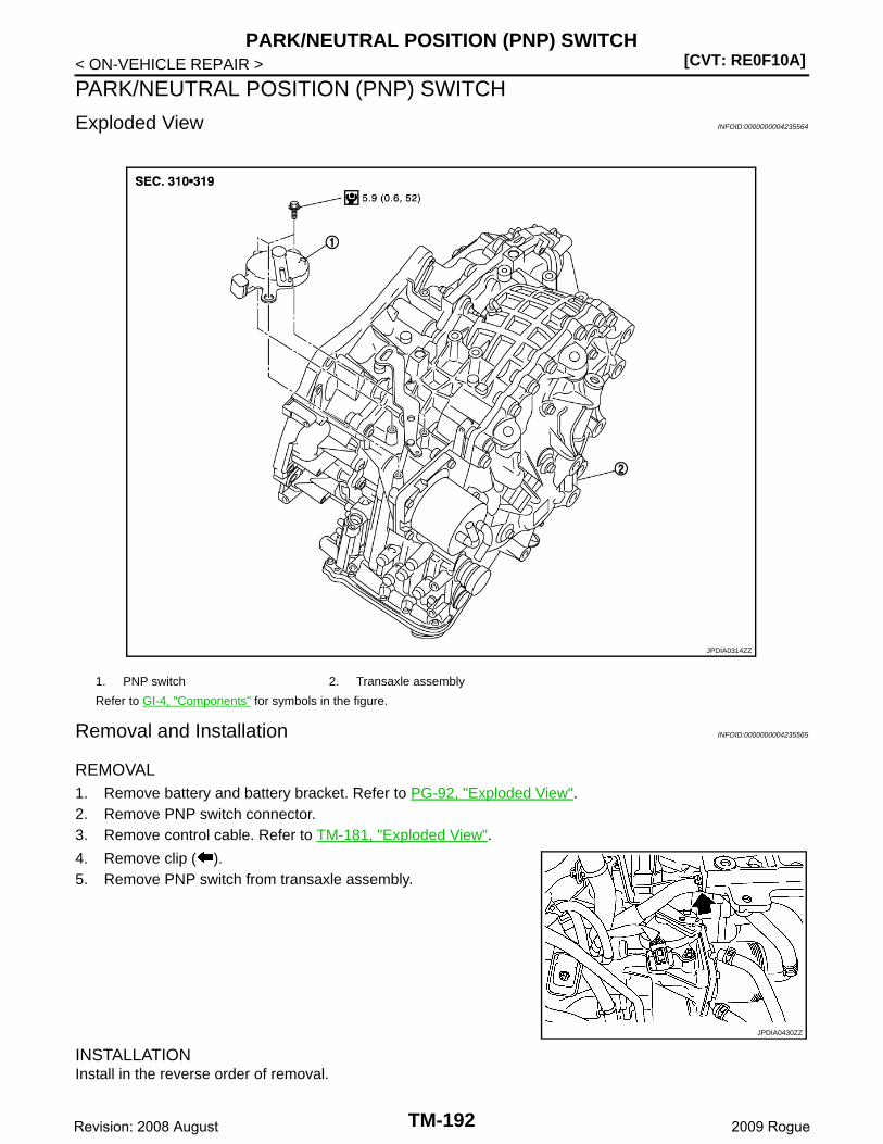
[CVT: RE0F10A]PARK/NEUTRAL POSITION (PNP) SWITCH
< ON-VEHICLE REPAIR >
PARK/NEUTRAL POSITION (PNP) SWITCH
Exploded View INFOID:0000000004235564
Removal and Installation INFOID:0000000004235565
REMOVAL1. Remove battery and battery bracket. Refer to PG-92, "Exploded View".2. Remove PNP switch connector.3. Remove control cable. Refer to TM-181, "Exploded View".
4. Remove clip ( ).5. Remove PNP switch from transaxle assembly.
INSTALLATIONInstall in the reverse order of removal.
1. PNP switch 2. Transaxle assembly
Refer to GI-4, "Components" for symbols in the figure.
JPDIA0314ZZ
JPDIA0430ZZ
TM-192Revision: 2008 August 2009 Rogue
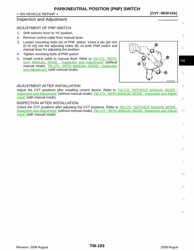
PARK/NEUTRAL POSITION (PNP) SWITCH[CVT: RE0F10A]
C
E
F
G
H
I
J
K
L
M
A
B
M
N
O
P
< ON-VEHICLE REPAIR >
T
Inspection and Adjustment INFOID:0000000004235566
ADJUSTMENT OF PNP SWITCH1. Shift selector lever to “N” position.2. Remove control cable from manual lever.3. Loosen mounting bolts (A) of PNP switch. Insert a pin [φ4 mm
(0.16 in)] into the adjusting holes (B) on both PNP switch andmanual lever for adjusting the position.
4. Tighten mounting bolts of PNP switch.5. Install control cable to manual lever. Refer to TM-172, "WITH-
OUT MANUAL MODE : Inspection and Adjustment" (withoutmanual mode), TM-172, "WITH MANUAL MODE : Inspectionand Adjustment" (with manual mode).
ADJUSTMENT AFTER INSTALLATION Adjust the CVT positions after installing control device. Refer to TM-172, "WITHOUT MANUAL MODE :Inspection and Adjustment" (without manual mode), TM-172, "WITH MANUAL MODE : Inspection and Adjust-ment" (with manual mode).
INSPECTION AFTER INSTALLATIONCheck the CVT positions after adjusting the CVT positions. Refer to TM-172, "WITHOUT MANUAL MODE :Inspection and Adjustment" (without manual mode), TM-172, "WITH MANUAL MODE : Inspection and Adjust-ment" (with manual mode).
SCIA6635J
TM-193Revision: 2008 August 2009 Rogue
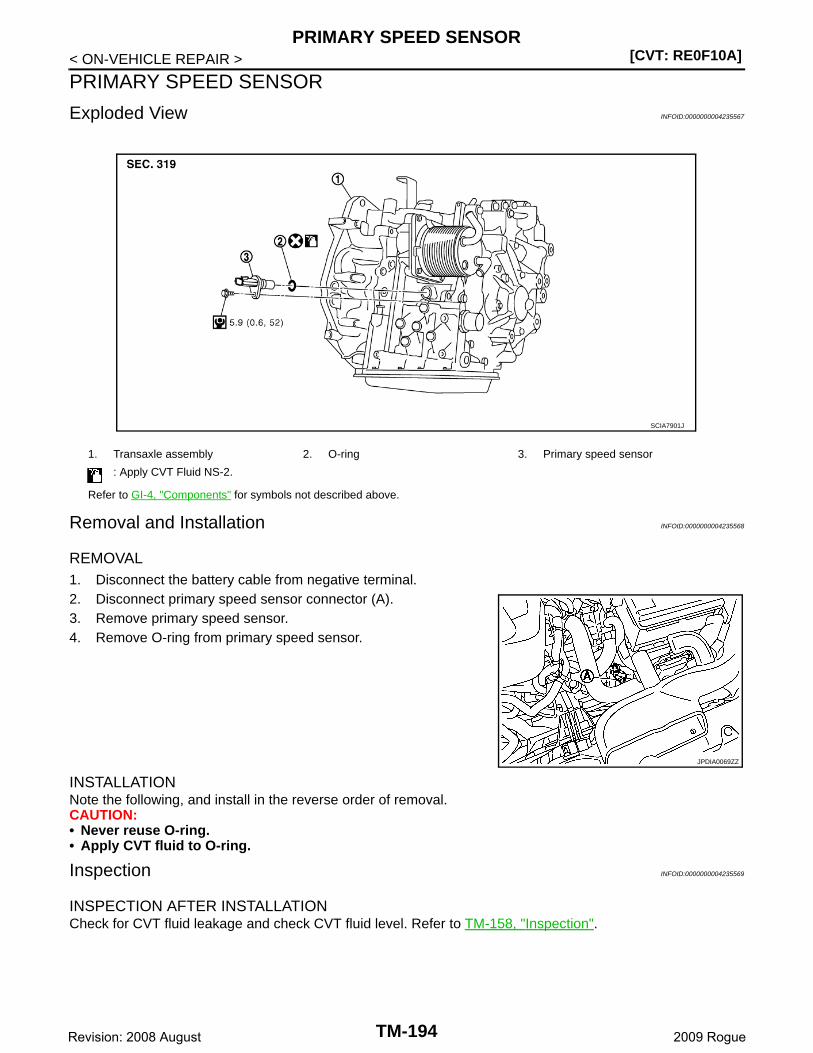
[CVT: RE0F10A]PRIMARY SPEED SENSOR
< ON-VEHICLE REPAIR >
PRIMARY SPEED SENSOR
Exploded View INFOID:0000000004235567
Removal and Installation INFOID:0000000004235568
REMOVAL1. Disconnect the battery cable from negative terminal.2. Disconnect primary speed sensor connector (A).3. Remove primary speed sensor.4. Remove O-ring from primary speed sensor.
INSTALLATIONNote the following, and install in the reverse order of removal.CAUTION:• Never reuse O-ring.• Apply CVT fluid to O-ring.
Inspection INFOID:0000000004235569
INSPECTION AFTER INSTALLATION Check for CVT fluid leakage and check CVT fluid level. Refer to TM-158, "Inspection".
1. Transaxle assembly 2. O-ring 3. Primary speed sensor
: Apply CVT Fluid NS-2.
Refer to GI-4, "Components" for symbols not described above.
SCIA7901J
JPDIA0069ZZ
TM-194Revision: 2008 August 2009 Rogue
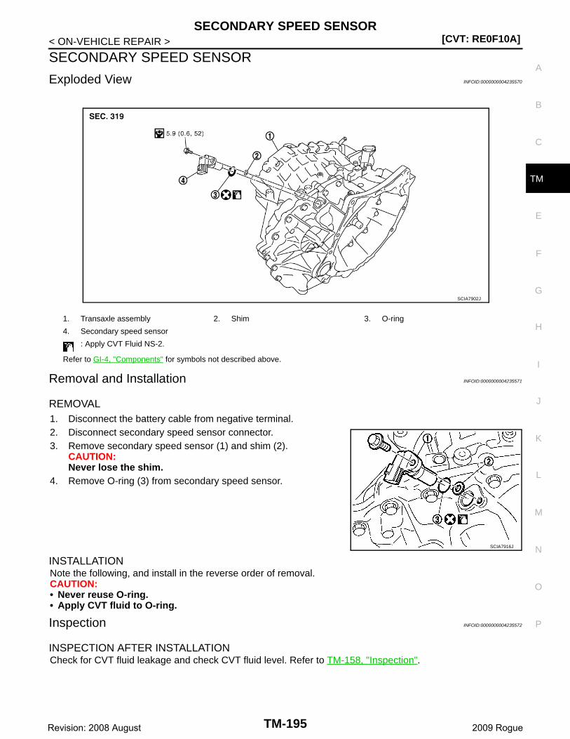
SECONDARY SPEED SENSOR[CVT: RE0F10A]
C
E
F
G
H
I
J
K
L
M
A
B
M
N
O
P
< ON-VEHICLE REPAIR >
T
SECONDARY SPEED SENSOR
Exploded View INFOID:0000000004235570
Removal and Installation INFOID:0000000004235571
REMOVAL1. Disconnect the battery cable from negative terminal.2. Disconnect secondary speed sensor connector.3. Remove secondary speed sensor (1) and shim (2).
CAUTION:Never lose the shim.
4. Remove O-ring (3) from secondary speed sensor.
INSTALLATIONNote the following, and install in the reverse order of removal.CAUTION:• Never reuse O-ring.• Apply CVT fluid to O-ring.
Inspection INFOID:0000000004235572
INSPECTION AFTER INSTALLATIONCheck for CVT fluid leakage and check CVT fluid level. Refer to TM-158, "Inspection".
1. Transaxle assembly 2. Shim 3. O-ring
4. Secondary speed sensor
: Apply CVT Fluid NS-2.
Refer to GI-4, "Components" for symbols not described above.
SCIA7902J
SCIA7916J
TM-195Revision: 2008 August 2009 Rogue
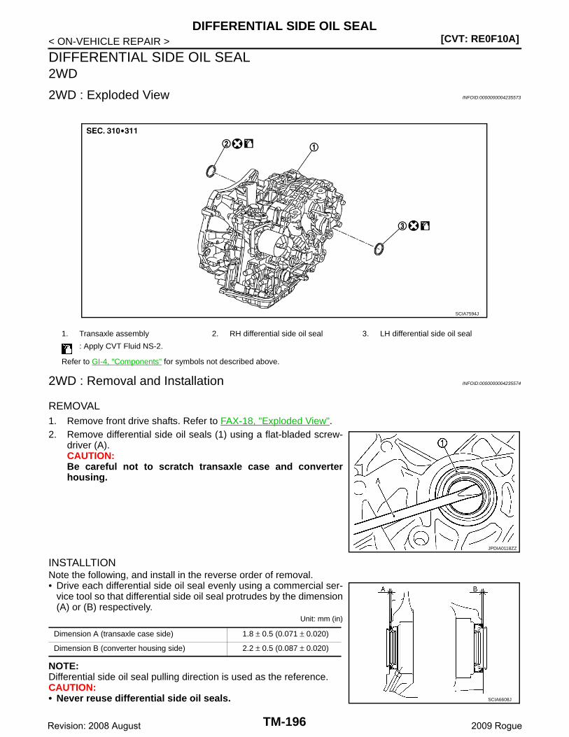
[CVT: RE0F10A]DIFFERENTIAL SIDE OIL SEAL
< ON-VEHICLE REPAIR >
DIFFERENTIAL SIDE OIL SEAL2WD
2WD : Exploded View INFOID:0000000004235573
2WD : Removal and Installation INFOID:0000000004235574
REMOVAL1. Remove front drive shafts. Refer to FAX-18, "Exploded View".2. Remove differential side oil seals (1) using a flat-bladed screw-
driver (A).CAUTION:Be careful not to scratch transaxle case and converterhousing.
INSTALLTIONNote the following, and install in the reverse order of removal.• Drive each differential side oil seal evenly using a commercial ser-
vice tool so that differential side oil seal protrudes by the dimension(A) or (B) respectively.
Unit: mm (in)
NOTE:Differential side oil seal pulling direction is used as the reference.CAUTION:• Never reuse differential side oil seals.
1. Transaxle assembly 2. RH differential side oil seal 3. LH differential side oil seal
: Apply CVT Fluid NS-2.
Refer to GI-4, "Components" for symbols not described above.
SCIA7594J
JPDIA0118ZZ
Dimension A (transaxle case side) 1.8 ± 0.5 (0.071 ± 0.020)
Dimension B (converter housing side) 2.2 ± 0.5 (0.087 ± 0.020)
SCIA6608J
TM-196Revision: 2008 August 2009 Rogue
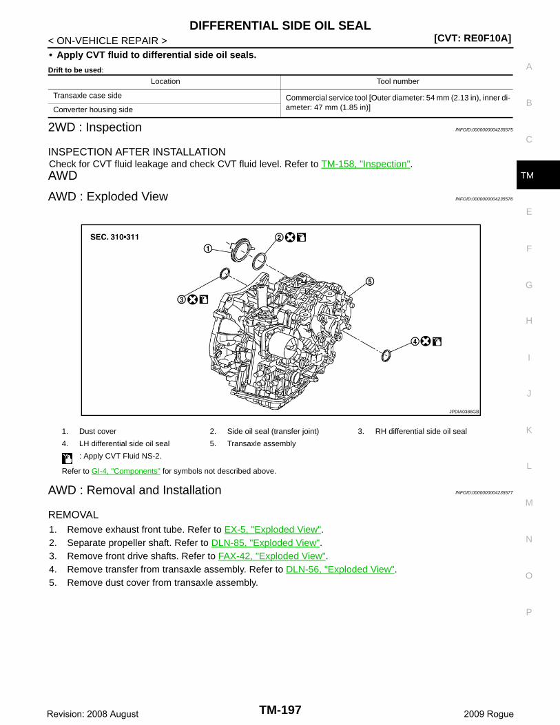
DIFFERENTIAL SIDE OIL SEAL[CVT: RE0F10A]
C
E
F
G
H
I
J
K
L
M
A
B
M
N
O
P
< ON-VEHICLE REPAIR >
T
• Apply CVT fluid to differential side oil seals.
Drift to be used:
2WD : Inspection INFOID:0000000004235575
INSPECTION AFTER INSTALLATIONCheck for CVT fluid leakage and check CVT fluid level. Refer to TM-158, "Inspection".AWD
AWD : Exploded View INFOID:0000000004235576
AWD : Removal and Installation INFOID:0000000004235577
REMOVAL1. Remove exhaust front tube. Refer to EX-5, "Exploded View".2. Separate propeller shaft. Refer to DLN-85, "Exploded View".3. Remove front drive shafts. Refer to FAX-42, "Exploded View".4. Remove transfer from transaxle assembly. Refer to DLN-56, "Exploded View".5. Remove dust cover from transaxle assembly.
Location Tool number
Transaxle case side Commercial service tool [Outer diameter: 54 mm (2.13 in), inner di-ameter: 47 mm (1.85 in)]Converter housing side
1. Dust cover 2. Side oil seal (transfer joint) 3. RH differential side oil seal
4. LH differential side oil seal 5. Transaxle assembly
: Apply CVT Fluid NS-2.
Refer to GI-4, "Components" for symbols not described above.
JPDIA0386GB
TM-197Revision: 2008 August 2009 Rogue
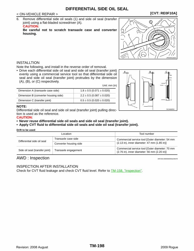
[CVT: RE0F10A]DIFFERENTIAL SIDE OIL SEAL
< ON-VEHICLE REPAIR >6. Remove differential side oil seals (1) and side oil seal (transfer
joint) using a flat-bladed screwdriver (A).CAUTION:Be careful not to scratch transaxle case and converterhousing.
INSTALLTIONNote the following, and install in the reverse order of removal.• Drive each differential side oil seal and side oil seal (transfer joint)
evenly using a commercial service tool so that differential side oilseal and side oil seal (transfer joint) protrudes by the dimension(A), (B), or (C) respectively.
Unit: mm (in)
NOTE:Differential side oil seal and side oil seal (transfer joint) pulling direc-tion is used as the reference.CAUTION:• Never reuse differential side oil seals and side oil seal (transfer joint).• Apply CVT fluid to differential side oil seals and side oil seal (transfer joint).
Drift to be used:
AWD : Inspection INFOID:0000000004235578
INSPECTION AFTER INSTALLATIONCheck for CVT fluid leakage and check CVT fluid level. Refer to TM-158, "Inspection".
JPDIA0118ZZ
Dimension A (transaxle case side) 1.8 ± 0.5 (0.071 ± 0.020)
Dimension B (converter housing side) 2.2 ± 0.5 (0.087 ± 0.020)
Dimension C (transfer joint) 0.5 ± 0.5 (0.020 ± 0.020)
SCIA6609J
Location Tool number
Differential side oil sealTransaxle case side Commercial service tool [Outer diameter: 54 mm
(2.13 in), inner diameter: 47 mm (1.85 in)]Converter housing side
Side oil seal (transfer joint) Transaxle engagementCommercial service tool [Outer diameter: 70 mm (2.76 in), inner diameter: 56 mm (2.20 in)]
TM-198Revision: 2008 August 2009 Rogue
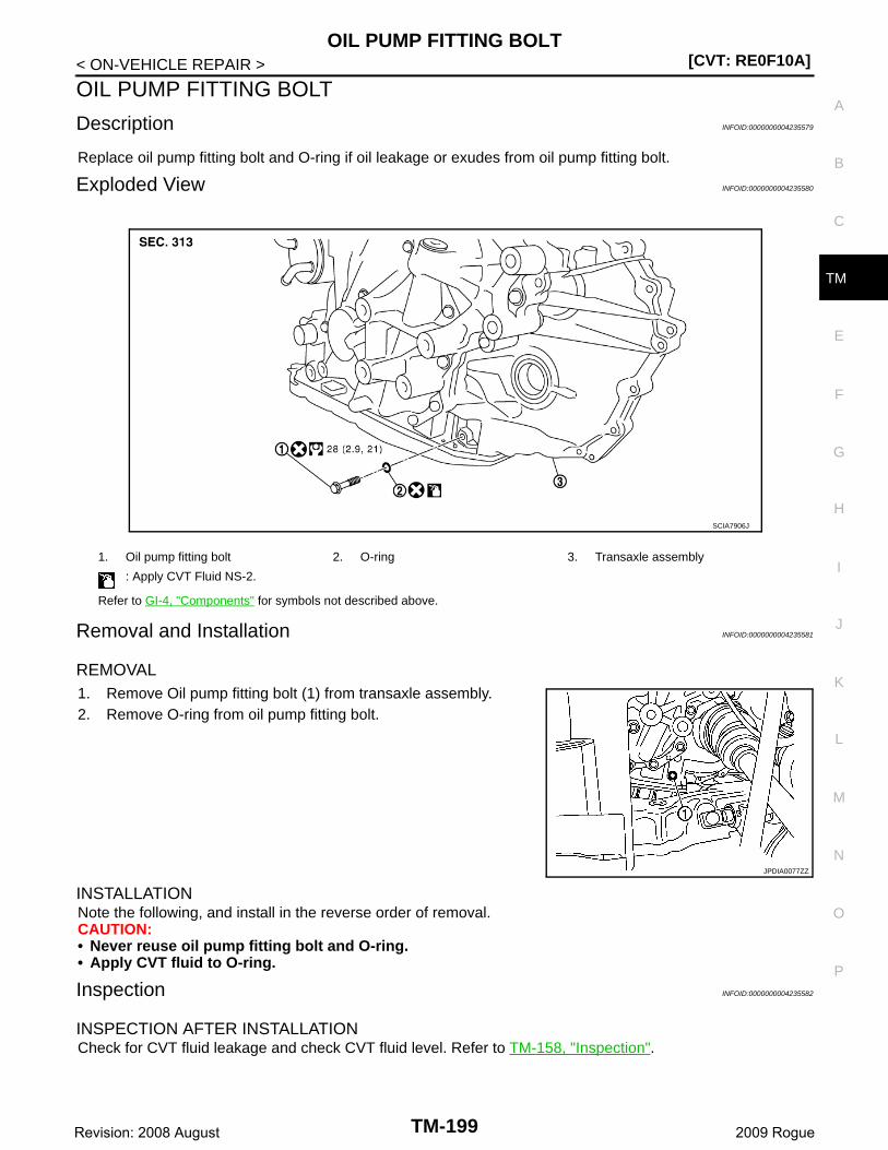
OIL PUMP FITTING BOLT[CVT: RE0F10A]
C
E
F
G
H
I
J
K
L
M
A
B
M
N
O
P
< ON-VEHICLE REPAIR >
T
OIL PUMP FITTING BOLT
Description INFOID:0000000004235579
Replace oil pump fitting bolt and O-ring if oil leakage or exudes from oil pump fitting bolt.
Exploded View INFOID:0000000004235580
Removal and Installation INFOID:0000000004235581
REMOVAL1. Remove Oil pump fitting bolt (1) from transaxle assembly.2. Remove O-ring from oil pump fitting bolt.
INSTALLATIONNote the following, and install in the reverse order of removal.CAUTION:• Never reuse oil pump fitting bolt and O-ring.• Apply CVT fluid to O-ring.
Inspection INFOID:0000000004235582
INSPECTION AFTER INSTALLATIONCheck for CVT fluid leakage and check CVT fluid level. Refer to TM-158, "Inspection".
1. Oil pump fitting bolt 2. O-ring 3. Transaxle assembly
: Apply CVT Fluid NS-2.
Refer to GI-4, "Components" for symbols not described above.
SCIA7906J
JPDIA0077ZZ
TM-199Revision: 2008 August 2009 Rogue
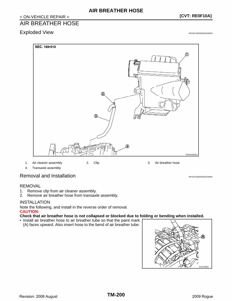
[CVT: RE0F10A]AIR BREATHER HOSE
< ON-VEHICLE REPAIR >
AIR BREATHER HOSE
Exploded View INFOID:0000000004235583
Removal and Installation INFOID:0000000004235584
REMOVAL1. Remove clip from air cleaner assembly. 2. Remove air breather hose from transaxle assembly.
INSTALLATIONNote the following, and install in the reverse order of removal.CAUTION:Check that air breather hose is not collapsed or blocked due to folding or bending when installed.• Install air breather hose to air breather tube so that the paint mark
(A) faces upward. Also insert hose to the bend of air breather tube.
1. Air cleaner assembly 2. Clip 3. Air breather hose
4. Transaxle assembly
JPDIA0356ZZ
SCIA7584J
TM-200Revision: 2008 August 2009 Rogue
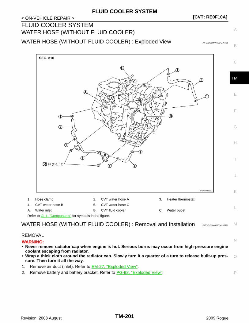
FLUID COOLER SYSTEM[CVT: RE0F10A]
C
E
F
G
H
I
J
K
L
M
A
B
M
N
O
P
< ON-VEHICLE REPAIR >
T
FLUID COOLER SYSTEMWATER HOSE (WITHOUT FLUID COOLER)
WATER HOSE (WITHOUT FLUID COOLER) : Exploded View INFOID:0000000004235585
WATER HOSE (WITHOUT FLUID COOLER) : Removal and Installation INFOID:0000000004235586
REMOVALWARNING:• Never remove radiator cap when engine is hot. Serious burns may occur from high-pressure engine
coolant escaping from radiator.• Wrap a thick cloth around the radiator cap. Slowly turn it a quarter of a turn to release built-up pres-
sure. Then turn it all the way.1. Remove air duct (inlet). Refer to EM-27, "Exploded View".2. Remove battery and battery bracket. Refer to PG-92, "Exploded View".
1. Hose clamp 2. CVT water hose A 3. Heater thermostat
4. CVT water hose B 5. CVT water hose C
A. Water inlet B. CVT fluid cooler C. Water outlet
Refer to GI-4, "Components" for symbols in the figure.
JPDIA0493ZZ
TM-201Revision: 2008 August 2009 Rogue

[CVT: RE0F10A]FLUID COOLER SYSTEM
< ON-VEHICLE REPAIR >3. Remove hose clamps (1), and remove CVT water hose A (2).4. Remove hose clamps (1), and remove CVT water hose B (3).5. Remove heater thermostat (4) from transaxle assembly.
6. Remove clip ( ).7. Remove hose clamps (1), and remove CVT water hose C (2).
INSTALLATIONNote the following, and install in the reverse order of removal.
*: Refer to the illustrations for the specific position of each hose clamp tab.
• The illustrations indicate the view from the hose ends.
• When installing hose clamps the center line of each clamp tabshould be positioned as shown in the figure.
JPDIA0511ZZ
JPDIA0551ZZ
CVT water hose Hose end Paint mark Position of hose clamp*
CVT water hose AWater inlet Facing upward C
Heater thermostat Facing forward C
CVT water hose BHeater thermostat Facing forward B
CVT fluid cooler Facing to the left of the vehicle C
CVT water hose C
CVT fluid cooler Facing forward A
Water outletFacing downward left of the ve-hicle at 45° D
E : Upper
JPDIA0497ZZ
TM-202Revision: 2008 August 2009 Rogue

FLUID COOLER SYSTEM[CVT: RE0F10A]
C
E
F
G
H
I
J
K
L
M
A
B
M
N
O
P
< ON-VEHICLE REPAIR >
T
• Insert CVT water hose according to dimension (A) describedbelow.
• Set hose clamps (1) from the end of fluid cooler hose (2) accordingto dimension (A) described below.
• Hose clamp should not interfere with the bulge.
WATER HOSE (WITHOUT FLUID COOLER) : Inspection INFOID:0000000004235587
INSPECTION AFTER REMOVALHeater Thermostat• Fully immerse the heater thermostat (1) in a container (A) filled
with water. Continue heating the water while stirring.• Continue heating the heater thermostat for 5 minutes or more after
bringing the water to a boil.• Quickly take the heater thermostat out of the hot water, measure
the heater thermostat within 10 seconds.
• Place dial indicator (A) on the pellet (B) and measure the elonga-tion from the initial state.
• If out of the standard, replace heater thermostat.
INSPECTION AFTER INSTALLATIONCheck for engine coolant leakage and check engine coolant level. Refer to CO-9, "Inspection".WATER HOSE (WITH FLUID COOLER)
(1) (2) Distance A
CVT water hose AWater inlet
27 mm (1.06 in)Heater thermostat
CVT water hose B
Heater thermostat
CVT fluid coolerEnd reaches the tube
bend R position.
CVT water hose CCVT fluid cooler
End reaches the tube bend R position.
Water outlet 27 mm (1.06 in)
SCIA7203E
Dimension A : 5 – 7 mm (0.20 – 0.28 in)
SCIA8123E
JPBIA0318ZZ
Standard : TM-221, "Heater Thermostat"
JPBIA0319ZZ
TM-203Revision: 2008 August 2009 Rogue

[CVT: RE0F10A]FLUID COOLER SYSTEM
< ON-VEHICLE REPAIR >
WATER HOSE (WITH FLUID COOLER) : Exploded View INFOID:0000000004235588
WATER HOSE (WITH FLUID COOLER) : Removal and Installation INFOID:0000000004235589
REMOVALWARNING:• Never remove radiator cap when engine is hot. Serious burns may occur from high-pressure engine
coolant escaping from radiator.• Wrap a thick cloth around the radiator cap. Slowly turn it a quarter of a turn to release built-up pres-
sure. Then turn it all the way.1. Remove air duct (inlet). Refer to EM-27, "Exploded View".2. Remove battery and battery bracket. Refer to PG-92, "Exploded View".
1. Hose clamp 2. CVT water hose A 3. CVT water tube
4. CVT water hose B 5. CVT water hose C
A. Water inlet B. CVT fluid cooler C. Water outlet
Refer to GI-4, "Components" for symbols in the figure.
JPDIA0360GB
TM-204Revision: 2008 August 2009 Rogue
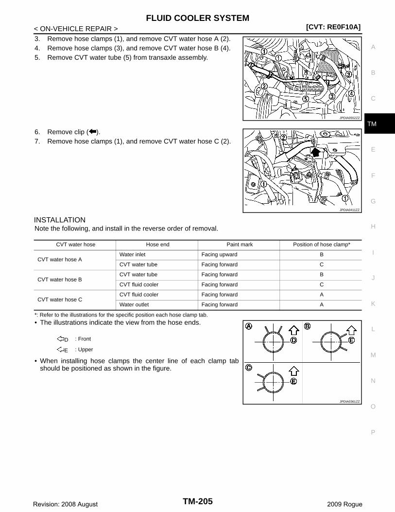
FLUID COOLER SYSTEM[CVT: RE0F10A]
C
E
F
G
H
I
J
K
L
M
A
B
M
N
O
P
< ON-VEHICLE REPAIR >
T
3. Remove hose clamps (1), and remove CVT water hose A (2).4. Remove hose clamps (3), and remove CVT water hose B (4).5. Remove CVT water tube (5) from transaxle assembly.
6. Remove clip ( ).7. Remove hose clamps (1), and remove CVT water hose C (2).
INSTALLATIONNote the following, and install in the reverse order of removal.
*: Refer to the illustrations for the specific position each hose clamp tab.
• The illustrations indicate the view from the hose ends.
• When installing hose clamps the center line of each clamp tabshould be positioned as shown in the figure.
JPDIA0552ZZ
JPDIA0411ZZ
CVT water hose Hose end Paint mark Position of hose clamp*
CVT water hose AWater inlet Facing upward B
CVT water tube Facing forward C
CVT water hose BCVT water tube Facing forward B
CVT fluid cooler Facing forward C
CVT water hose CCVT fluid cooler Facing forward A
Water outlet Facing forward A
D : Front
E : Upper
JPDIA0361ZZ
TM-205Revision: 2008 August 2009 Rogue
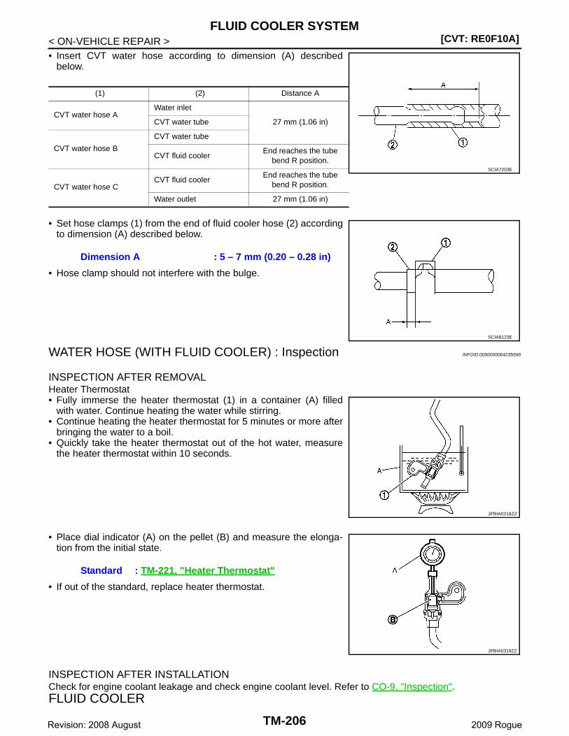
[CVT: RE0F10A]FLUID COOLER SYSTEM
< ON-VEHICLE REPAIR >• Insert CVT water hose according to dimension (A) described
below.
• Set hose clamps (1) from the end of fluid cooler hose (2) accordingto dimension (A) described below.
• Hose clamp should not interfere with the bulge.
WATER HOSE (WITH FLUID COOLER) : Inspection INFOID:0000000004235590
INSPECTION AFTER REMOVALHeater Thermostat• Fully immerse the heater thermostat (1) in a container (A) filled
with water. Continue heating the water while stirring.• Continue heating the heater thermostat for 5 minutes or more after
bringing the water to a boil.• Quickly take the heater thermostat out of the hot water, measure
the heater thermostat within 10 seconds.
• Place dial indicator (A) on the pellet (B) and measure the elonga-tion from the initial state.
• If out of the standard, replace heater thermostat.
INSPECTION AFTER INSTALLATIONCheck for engine coolant leakage and check engine coolant level. Refer to CO-9, "Inspection".FLUID COOLER
(1) (2) Distance A
CVT water hose AWater inlet
27 mm (1.06 in)CVT water tube
CVT water hose B
CVT water tube
CVT fluid coolerEnd reaches the tube
bend R position.
CVT water hose CCVT fluid cooler
End reaches the tube bend R position.
Water outlet 27 mm (1.06 in)
SCIA7203E
Dimension A : 5 – 7 mm (0.20 – 0.28 in)
SCIA8123E
JPBIA0318ZZ
Standard : TM-221, "Heater Thermostat"
JPBIA0319ZZ
TM-206Revision: 2008 August 2009 Rogue

FLUID COOLER SYSTEM[CVT: RE0F10A]
C
E
F
G
H
I
J
K
L
M
A
B
M
N
O
P
< ON-VEHICLE REPAIR >
T
FLUID COOLER : Exploded view INFOID:0000000004235591
FLUID COOLER : Removal and Installation INFOID:0000000004235592
REMOVAL1. Remove engine under cover with power tool.2. Remove front bumper assembly. Refer to EXT-13, "Exploded View".3. Remove air duct (inlet). Refer to EM-27, "Exploded View".4. Remove hose clamps (1) and fluid cooler hose A (2).
5. Remove hose clamps (3) and fluid cooler hose B (4).
1. Hose clamp 2. Fluid cooler hose A 3. Fluid cooler tube
4. Fluid cooler hose C 5. Bracket 6. Fluid cooler
7. Bracket 8. Fluid cooler hose D 9. Fluid cooler tube
10. Bracket 11. Fluid cooler hose B
A. To CVT fluid cooler
Refer to GI-4, "Components" for symbols in the figure.
JPDIA0529GB
: Vehicle front
JPDIA0415ZZ
TM-207Revision: 2008 August 2009 Rogue

[CVT: RE0F10A]FLUID COOLER SYSTEM
< ON-VEHICLE REPAIR >6. Remove hose clamps (1) and fluid cooler hose C (2).
7. Remove hose clamps (3) and fluid cooler hose D (4).8. Remove fluid cooler (5).9. Remove fluid cooler tubes and bracket.
INSTALLATIONNote the following, and install in the reverse order of removal.
*: Refer to the illustrations for the specific position of each hose clamp tab.
• The illustrations indicate the view from the hose ends.
• When installing hose clamps the center line of each clamp tabshould be positioned as shown in the figure.
: Vehicle front
JPDIA0553ZZ
Fluid cooler hose Hose end Paint mark Position of hose clamp*
Fluid cooler hose A
CVT fluid cooler side Facing upward B
Fluid cooler tube sideFacing upward left of the vehi-cle at 25° C
Fluid cooler hose B
CVT fluid cooler side Facing upward A
Fluid cooler tube sideFacing downward left of the ve-hicle at 25° F
Fluid cooler hose C
Fluid cooler side Facing forward D
Fluid cooler tube sideFacing upward left of the vehi-cle at 25° E
Fluid cooler hose D
Fluid cooler side Facing forward D
Fluid cooler tube sideFacing downward left of the ve-hicle at 25° G
: Upper
JPDIA0546ZZ
TM-208Revision: 2008 August 2009 Rogue
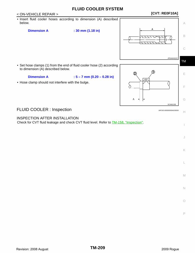
FLUID COOLER SYSTEM[CVT: RE0F10A]
C
E
F
G
H
I
J
K
L
M
A
B
M
N
O
P
< ON-VEHICLE REPAIR >
T
• Insert fluid cooler hoses according to dimension (A) describedbelow.
• Set hose clamps (1) from the end of fluid cooler hose (2) accordingto dimension (A) described below.
• Hose clamp should not interfere with the bulge.
FLUID COOLER : Inspection INFOID:0000000004235593
INSPECTION AFTER INSTALLATIONCheck for CVT fluid leakage and check CVT fluid level. Refer to TM-158, "Inspection".
Dimension A : 30 mm (1.18 in)
JPDIA0432ZZ
Dimension A : 5 – 7 mm (0.20 – 0.28 in)
SCIA8123E
TM-209Revision: 2008 August 2009 Rogue
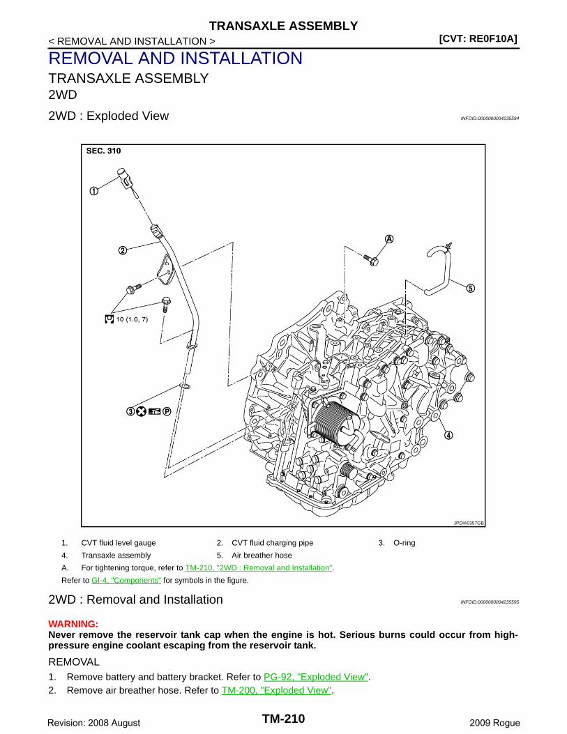
[CVT: RE0F10A]TRANSAXLE ASSEMBLY
< REMOVAL AND INSTALLATION >
REMOVAL AND INSTALLATIONTRANSAXLE ASSEMBLY2WD
2WD : Exploded View INFOID:0000000004235594
2WD : Removal and Installation INFOID:0000000004235595
WARNING:Never remove the reservoir tank cap when the engine is hot. Serious burns could occur from high-pressure engine coolant escaping from the reservoir tank.
REMOVAL1. Remove battery and battery bracket. Refer to PG-92, "Exploded View".2. Remove air breather hose. Refer to TM-200, "Exploded View".
1. CVT fluid level gauge 2. CVT fluid charging pipe 3. O-ring
4. Transaxle assembly 5. Air breather hose
A. For tightening torque, refer to TM-210, "2WD : Removal and Installation".
Refer to GI-4, "Components" for symbols in the figure.
JPDIA0357GB
TM-210Revision: 2008 August 2009 Rogue
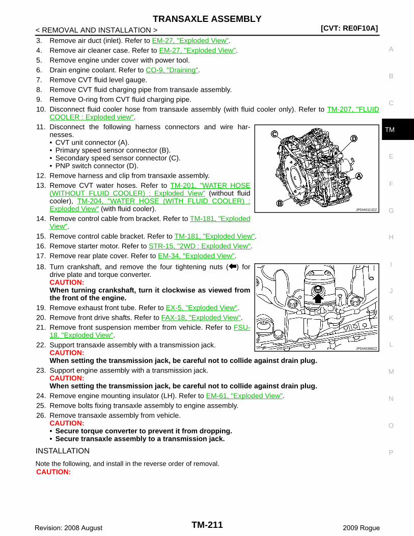
TRANSAXLE ASSEMBLY[CVT: RE0F10A]
C
E
F
G
H
I
J
K
L
M
A
B
M
N
O
P
< REMOVAL AND INSTALLATION >
T
3. Remove air duct (inlet). Refer to EM-27, "Exploded View".4. Remove air cleaner case. Refer to EM-27, "Exploded View".5. Remove engine under cover with power tool.6. Drain engine coolant. Refer to CO-9, "Draining".7. Remove CVT fluid level gauge.8. Remove CVT fluid charging pipe from transaxle assembly.9. Remove O-ring from CVT fluid charging pipe.10. Disconnect fluid cooler hose from transaxle assembly (with fluid cooler only). Refer to TM-207, "FLUID
COOLER : Exploded view".11. Disconnect the following harness connectors and wire har-
nesses.• CVT unit connector (A).• Primary speed sensor connector (B).• Secondary speed sensor connector (C).• PNP switch connector (D).
12. Remove harness and clip from transaxle assembly.13. Remove CVT water hoses. Refer to TM-201, "WATER HOSE
(WITHOUT FLUID COOLER) : Exploded View" (without fluidcooler), TM-204, "WATER HOSE (WITH FLUID COOLER) :Exploded View" (with fluid cooler).
14. Remove control cable from bracket. Refer to TM-181, "ExplodedView".
15. Remove control cable bracket. Refer to TM-181, "Exploded View".16. Remove starter motor. Refer to STR-15, "2WD : Exploded View".17. Remove rear plate cover. Refer to EM-34, "Exploded View".
18. Turn crankshaft, and remove the four tightening nuts ( ) fordrive plate and torque converter.CAUTION:When turning crankshaft, turn it clockwise as viewed fromthe front of the engine.
19. Remove exhaust front tube. Refer to EX-5, "Exploded View".20. Remove front drive shafts. Refer to FAX-18, "Exploded View".21. Remove front suspension member from vehicle. Refer to FSU-
18, "Exploded View".22. Support transaxle assembly with a transmission jack.
CAUTION:When setting the transmission jack, be careful not to collide against drain plug.
23. Support engine assembly with a transmission jack.CAUTION:When setting the transmission jack, be careful not to collide against drain plug.
24. Remove engine mounting insulator (LH). Refer to EM-61, "Exploded View".25. Remove bolts fixing transaxle assembly to engine assembly.26. Remove transaxle assembly from vehicle.
CAUTION:• Secure torque converter to prevent it from dropping.• Secure transaxle assembly to a transmission jack.
INSTALLATION
Note the following, and install in the reverse order of removal.CAUTION:
JPDIA0113ZZ
JPDIA0388ZZ
TM-211Revision: 2008 August 2009 Rogue
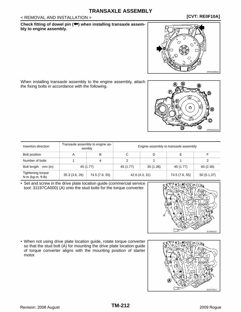
[CVT: RE0F10A]TRANSAXLE ASSEMBLY
< REMOVAL AND INSTALLATION >
Check fitting of dowel pin ( ) when installing transaxle assem-bly to engine assembly.
When installing transaxle assembly to the engine assembly, attachthe fixing bolts in accordance with the following.
• Set and screw in the drive plate location guide (commercial servicetool: 31197CA000) (A) onto the stud bolts for the torque converter.
• When not using drive plate location guide, rotate torque converterso that the stud bolt (A) for mounting the drive plate location guideof torque converter aligns with the mounting position of startermotor.
JPDIA0389ZZ
JPDIA0412ZZ
Insertion directionTransaxle assembly to engine as-
semblyEngine assembly to transaxle assembly
Bolt position A B C D E F
Number of bolts 1 4 2 2 1 2
Bolt length mm (in) 45 (1.77) 45 (1.77) 35 (1.38) 45 (1.77) 60 (2.36)
Tightening torqueN·m (kg-m, ft-lb)
35.3 (3.6, 26) 74.5 (7.6, 55) 42.6 (4.3, 31) 74.5 (7.6, 55) 50 (5.1,37)
SCIA6616J
SCIA7261J
TM-212Revision: 2008 August 2009 Rogue
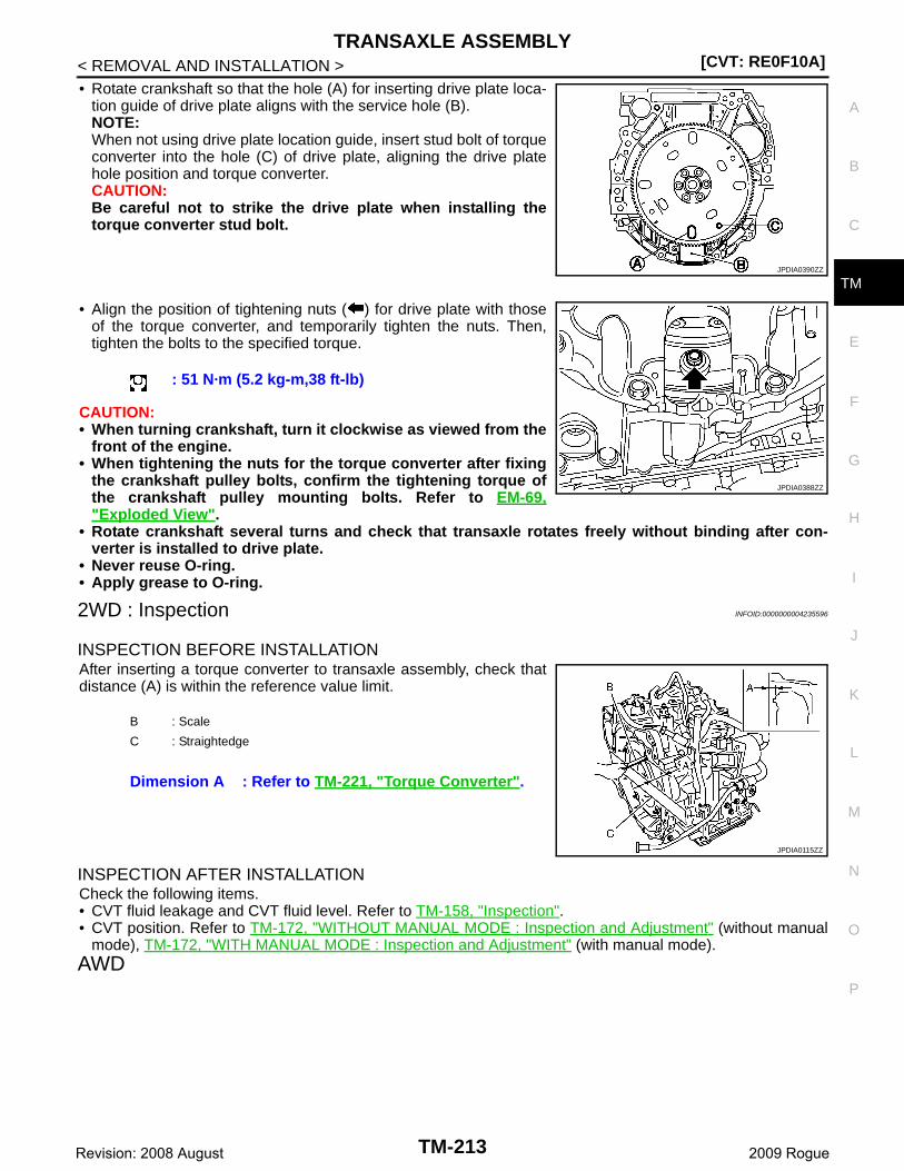
TRANSAXLE ASSEMBLY[CVT: RE0F10A]
C
E
F
G
H
I
J
K
L
M
A
B
M
N
O
P
< REMOVAL AND INSTALLATION >
T
• Rotate crankshaft so that the hole (A) for inserting drive plate loca-tion guide of drive plate aligns with the service hole (B).NOTE:When not using drive plate location guide, insert stud bolt of torqueconverter into the hole (C) of drive plate, aligning the drive platehole position and torque converter.CAUTION:Be careful not to strike the drive plate when installing thetorque converter stud bolt.
• Align the position of tightening nuts ( ) for drive plate with thoseof the torque converter, and temporarily tighten the nuts. Then,tighten the bolts to the specified torque.
CAUTION:• When turning crankshaft, turn it clockwise as viewed from the
front of the engine.• When tightening the nuts for the torque converter after fixing
the crankshaft pulley bolts, confirm the tightening torque ofthe crankshaft pulley mounting bolts. Refer to EM-69,"Exploded View".
• Rotate crankshaft several turns and check that transaxle rotates freely without binding after con-verter is installed to drive plate.
• Never reuse O-ring.• Apply grease to O-ring.
2WD : Inspection INFOID:0000000004235596
INSPECTION BEFORE INSTALLATIONAfter inserting a torque converter to transaxle assembly, check thatdistance (A) is within the reference value limit.
INSPECTION AFTER INSTALLATIONCheck the following items.• CVT fluid leakage and CVT fluid level. Refer to TM-158, "Inspection".• CVT position. Refer to TM-172, "WITHOUT MANUAL MODE : Inspection and Adjustment" (without manual
mode), TM-172, "WITH MANUAL MODE : Inspection and Adjustment" (with manual mode).AWD
JPDIA0390ZZ
: 51 N·m (5.2 kg-m,38 ft-lb)
JPDIA0388ZZ
B : Scale
C : Straightedge
Dimension A : Refer to TM-221, "Torque Converter".
JPDIA0115ZZ
TM-213Revision: 2008 August 2009 Rogue

[CVT: RE0F10A]TRANSAXLE ASSEMBLY
< REMOVAL AND INSTALLATION >
AWD : Exploded View INFOID:0000000004235597
AWD : Removal and Installation INFOID:0000000004235598
WARNING:Never remove the reservoir tank cap when the engine is hot. Serious burns could occur from high-pressure engine coolant escaping from the reservoir tank.
REMOVAL1. Remove battery and battery bracket. Refer to PG-92, "Exploded View".2. Remove air breather hose. Refer to TM-200, "Exploded View".3. Remove air duct (inlet). Refer to EM-27, "Exploded View".4. Remove air cleaner case. Refer to EM-27, "Exploded View".5. Remove engine under cover with power tool.6. Drain engine coolant. Refer to CO-9, "Draining".7. Remove CVT fluid level gauge.
1. CVT fluid level gauge 2. CVT fluid charging pipe 3. O-ring
4. Transaxle assembly 5. Air breather hose
A. For tightening torque, refer to TM-214, "AWD : Removal and Installation".
Refer to GI-4, "Components" for symbols in the figure.
JPDIA0357GB
TM-214Revision: 2008 August 2009 Rogue
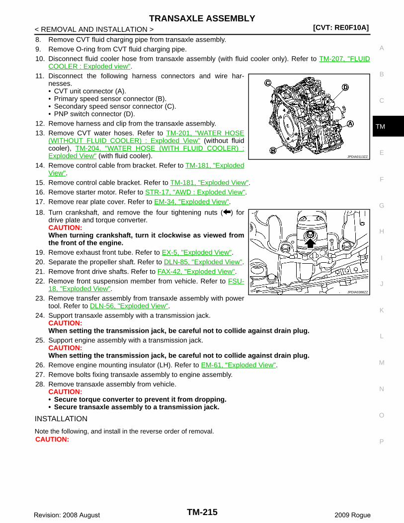
TRANSAXLE ASSEMBLY[CVT: RE0F10A]
C
E
F
G
H
I
J
K
L
M
A
B
M
N
O
P
< REMOVAL AND INSTALLATION >
T
8. Remove CVT fluid charging pipe from transaxle assembly.9. Remove O-ring from CVT fluid charging pipe.10. Disconnect fluid cooler hose from transaxle assembly (with fluid cooler only). Refer to TM-207, "FLUID
COOLER : Exploded view".11. Disconnect the following harness connectors and wire har-
nesses.• CVT unit connector (A).• Primary speed sensor connector (B).• Secondary speed sensor connector (C).• PNP switch connector (D).
12. Remove harness and clip from the transaxle assembly.13. Remove CVT water hoses. Refer to TM-201, "WATER HOSE
(WITHOUT FLUID COOLER) : Exploded View" (without fluidcooler), TM-204, "WATER HOSE (WITH FLUID COOLER) :Exploded View" (with fluid cooler).
14. Remove control cable from bracket. Refer to TM-181, "ExplodedView".
15. Remove control cable bracket. Refer to TM-181, "Exploded View".16. Remove starter motor. Refer to STR-17, "AWD : Exploded View".17. Remove rear plate cover. Refer to EM-34, "Exploded View".
18. Turn crankshaft, and remove the four tightening nuts ( ) fordrive plate and torque converter.CAUTION:When turning crankshaft, turn it clockwise as viewed fromthe front of the engine.
19. Remove exhaust front tube. Refer to EX-5, "Exploded View".20. Separate the propeller shaft. Refer to DLN-85, "Exploded View".21. Remove front drive shafts. Refer to FAX-42, "Exploded View".22. Remove front suspension member from vehicle. Refer to FSU-
18, "Exploded View".23. Remove transfer assembly from transaxle assembly with power
tool. Refer to DLN-56, "Exploded View".24. Support transaxle assembly with a transmission jack.
CAUTION:When setting the transmission jack, be careful not to collide against drain plug.
25. Support engine assembly with a transmission jack.CAUTION:When setting the transmission jack, be careful not to collide against drain plug.
26. Remove engine mounting insulator (LH). Refer to EM-61, "Exploded View".27. Remove bolts fixing transaxle assembly to engine assembly.28. Remove transaxle assembly from vehicle.
CAUTION:• Secure torque converter to prevent it from dropping.• Secure transaxle assembly to a transmission jack.
INSTALLATION
Note the following, and install in the reverse order of removal.CAUTION:
JPDIA0113ZZ
JPDIA0388ZZ
TM-215Revision: 2008 August 2009 Rogue

[CVT: RE0F10A]TRANSAXLE ASSEMBLY
< REMOVAL AND INSTALLATION >
Check fitting of dowel pin ( ) when installing transaxle assem-bly to engine assembly.
When installing transaxle assembly to the engine assembly, attachthe fixing bolts in accordance with the following.
• Set and screw in the drive plate location guide (commercial servicetool: 31197CA000) (A) onto the stud bolts for the torque converter.
• When not using drive plate location guide, rotate torque converterso that the stud bolt (A) for mounting the drive plate location guideof torque converter aligns with the mounting position of startermotor.
JPDIA0389ZZ
JPDIA0412ZZ
Insertion directionTransaxle assembly to engine as-
semblyEngine assembly to transaxle assembly
Bolt position A B C D E F
Number of bolts 1 4 2 2 1 2
Bolt length mm (in) 45 (1.77) 45 (1.77) 35 (1.38) 45 (1.77) 60 (2.36)
Tightening torqueN·m (kg-m, ft-lb)
35.3 (3.6, 26) 74.5 (7.6, 55) 42.6 (4.3, 31) 74.5 (7.6, 55) 50 (5.1,37)
SCIA6616J
SCIA7261J
TM-216Revision: 2008 August 2009 Rogue
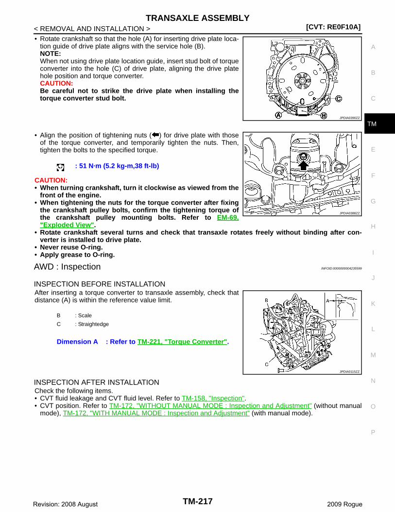
TRANSAXLE ASSEMBLY[CVT: RE0F10A]
C
E
F
G
H
I
J
K
L
M
A
B
M
N
O
P
< REMOVAL AND INSTALLATION >
T
• Rotate crankshaft so that the hole (A) for inserting drive plate loca-tion guide of drive plate aligns with the service hole (B).NOTE:When not using drive plate location guide, insert stud bolt of torqueconverter into the hole (C) of drive plate, aligning the drive platehole position and torque converter.CAUTION:Be careful not to strike the drive plate when installing thetorque converter stud bolt.
• Align the position of tightening nuts ( ) for drive plate with thoseof the torque converter, and temporarily tighten the nuts. Then,tighten the bolts to the specified torque.
CAUTION:• When turning crankshaft, turn it clockwise as viewed from the
front of the engine.• When tightening the nuts for the torque converter after fixing
the crankshaft pulley bolts, confirm the tightening torque ofthe crankshaft pulley mounting bolts. Refer to EM-69,"Exploded View".
• Rotate crankshaft several turns and check that transaxle rotates freely without binding after con-verter is installed to drive plate.
• Never reuse O-ring.• Apply grease to O-ring.
AWD : Inspection INFOID:0000000004235599
INSPECTION BEFORE INSTALLATIONAfter inserting a torque converter to transaxle assembly, check thatdistance (A) is within the reference value limit.
INSPECTION AFTER INSTALLATIONCheck the following items.• CVT fluid leakage and CVT fluid level. Refer to TM-158, "Inspection".• CVT position. Refer to TM-172, "WITHOUT MANUAL MODE : Inspection and Adjustment" (without manual
mode), TM-172, "WITH MANUAL MODE : Inspection and Adjustment" (with manual mode).
JPDIA0390ZZ
: 51 N·m (5.2 kg-m,38 ft-lb)
JPDIA0388ZZ
B : Scale
C : Straightedge
Dimension A : Refer to TM-221, "Torque Converter".
JPDIA0115ZZ
TM-217Revision: 2008 August 2009 Rogue
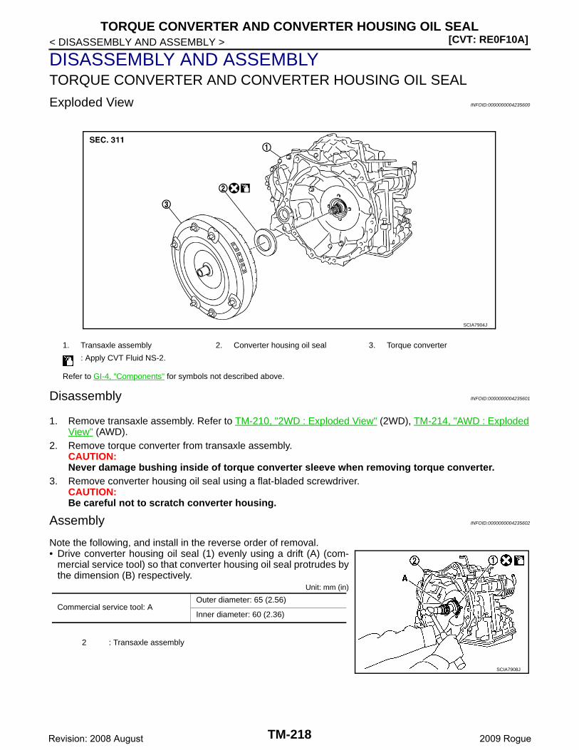
[CVT: RE0F10A]TORQUE CONVERTER AND CONVERTER HOUSING OIL SEAL
< DISASSEMBLY AND ASSEMBLY >
DISASSEMBLY AND ASSEMBLYTORQUE CONVERTER AND CONVERTER HOUSING OIL SEAL
Exploded View INFOID:0000000004235600
Disassembly INFOID:0000000004235601
1. Remove transaxle assembly. Refer to TM-210, "2WD : Exploded View" (2WD), TM-214, "AWD : ExplodedView" (AWD).
2. Remove torque converter from transaxle assembly.CAUTION:Never damage bushing inside of torque converter sleeve when removing torque converter.
3. Remove converter housing oil seal using a flat-bladed screwdriver.CAUTION:Be careful not to scratch converter housing.
Assembly INFOID:0000000004235602
Note the following, and install in the reverse order of removal.• Drive converter housing oil seal (1) evenly using a drift (A) (com-
mercial service tool) so that converter housing oil seal protrudes bythe dimension (B) respectively.
Unit: mm (in)
1. Transaxle assembly 2. Converter housing oil seal 3. Torque converter
: Apply CVT Fluid NS-2.
Refer to GI-4, "Components" for symbols not described above.
SCIA7904J
Commercial service tool: AOuter diameter: 65 (2.56)
Inner diameter: 60 (2.36)
2 : Transaxle assembly
SCIA7908J
TM-218Revision: 2008 August 2009 Rogue
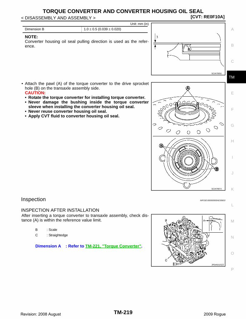
TORQUE CONVERTER AND CONVERTER HOUSING OIL SEAL[CVT: RE0F10A]
C
E
F
G
H
I
J
K
L
M
A
B
M
N
O
P
< DISASSEMBLY AND ASSEMBLY >
T
Unit: mm (in)
NOTE:Converter housing oil seal pulling direction is used as the refer-ence.
• Attach the pawl (A) of the torque converter to the drive sprockethole (B) on the transaxle assembly side.CAUTION:• Rotate the torque converter for installing torque converter.• Never damage the bushing inside the torque converter
sleeve when installing the converter housing oil seal.• Never reuse converter housing oil seal.• Apply CVT fluid to converter housing oil seal.
Inspection INFOID:0000000004235603
INSPECTION AFTER INSTALLATIONAfter inserting a torque converter to transaxle assembly, check dis-tance (A) is within the reference value limit.
Dimension B 1.0 ± 0.5 (0.039 ± 0.020)
SCIA7909J
SCIA7907J
B : Scale
C : Straightedge
Dimension A : Refer to TM-221, "Torque Converter".
JPDIA0115ZZ
TM-219Revision: 2008 August 2009 Rogue
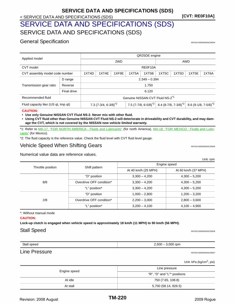
[CVT: RE0F10A]SERVICE DATA AND SPECIFICATIONS (SDS)
< SERVICE DATA AND SPECIFICATIONS (SDS)
SERVICE DATA AND SPECIFICATIONS (SDS)SERVICE DATA AND SPECIFICATIONS (SDS)
General Specification INFOID:0000000004235604
*1: Refer to MA-17, "FOR NORTH AMERICA : Fluids and Lubricants" (for north America), MA-18, "FOR MEXICO : Fluids and Lubri-cants" (for Mexico).
*2: The fluid capacity is the reference value. Check the fluid level with CVT fluid level gauge.
Vehicle Speed When Shifting Gears INFOID:0000000004235605
Numerical value data are reference values.Unit: rpm
*: Without manual mode
CAUTION:
Lock-up clutch is engaged when vehicle speed is approximately 18 km/h (11 MPH) to 90 km/h (56 MPH).
Stall Speed INFOID:0000000004235606
Line Pressure INFOID:0000000004235607
Unit: kPa (kg/cm2, psi)
Applied modelQR25DE engine
2WD AWD
CVT model RE0F10A
CVT assembly model code number 1XT4D 1XT4E 1XF9E 1XT5A 1XT5B 1XT5C 1XT5D 1XT5E 1XT6A
Transmission gear ratio
D range 2.349 – 0.394
Reverse 1.750
Final drive 6.120
Recommended fluid Genuine NISSAN CVT Fluid NS-2*1
Fluid capacity liter (US qt, Imp qt) 7.3 (7-3/4, 6-3/8)*2 7.5 (7-7/8, 6-5/8)*2 8.4 (8-7/8, 7-3/8)*2 8.6 (9-1/8, 7-5/8)*2
CAUTION:• Use only Genuine NISSAN CVT Fluid NS-2. Never mix with other fluid.• Using CVT fluid other than Genuine NISSAN CVT Fluid NS-2 will deteriorate in driveability and CVT durability, and may dam-
age the CVT, which is not covered by the NISSAN new vehicle limited warranty.
Throttle position Shift patternEngine speed
At 40 km/h (25 MPH) At 60 km/h (37 MPH)
8/8
“D” position 3,300 – 4,200 4,300 – 5,200
Overdrive OFF condition* 3,300 – 4,200 4,300 – 5,200
“L” position* 3,300 – 4,200 4,300 – 5,200
2/8
“D” position 1,000 – 2,800 1,200 – 3,200
Overdrive OFF condition* 2,200 – 3,000 2,800 – 3,600
“L” position* 3,200 – 4,100 4,100 – 4,900
Stall speed 2,500 – 3,000 rpm
Engine speedLine pressure
“R”, “D” and “L”* positions
At idle 750 (7.65, 108.8)
At stall 5,700 (58.14, 826.5)
TM-220Revision: 2008 August 2009 Rogue

SERVICE DATA AND SPECIFICATIONS (SDS)[CVT: RE0F10A]
C
E
F
G
H
I
J
K
L
M
A
B
M
N
O
P
< SERVICE DATA AND SPECIFICATIONS (SDS)
T
*: Without manual mode
Solenoid Valves INFOID:0000000004235608
CVT Fluid Temperature Sensor INFOID:0000000004235609
Primary Speed Sensor INFOID:0000000004235610
Secondary Speed Sensor INFOID:0000000004235611
Heater Thermostat INFOID:0000000004235612
Standard
Reference value
Torque Converter INFOID:0000000004235613
Name Terminal Resistance (Approx.)
Pressure control solenoid valve B (secondary pressure solenoid valve)
3
3.0 – 9.0 ΩPressure control solenoid valve A (line pressure solenoid valve) 2
Torque converter clutch solenoid valve 12
Lock-up select solenoid valve 13 17.0 – 38.0 Ω
Name ConditionCONSULT-III “DATA MONITOR” (Approx.)
Resistance (Approx.)
CVT fluid temperature sensorWhen CVT fluid temperature is 20°C (68°F) 2.0 V 6.5 kΩ
When CVT fluid temperature is 80°C (176°F) 1.0 V 0.9 kΩ
Name Condition Data (Approx.)
Primary speed sensorWithout manual mode When driving [“L” position, 20 km/h (12 MPH)] 900 Hz
With manual mode When driving [“M1” position, 20 km/h (12 MPH)] 760 Hz
Name Condition Data (Approx.)
Secondary speed sensor When driving [“D” position, 20 km/h (12 MPH)] 470 Hz
Valve lift More than 4.5 mm (0.177 in)
Valve opening temperature 82°C (180°F)
Maximum valve lift 5.0 mm/95°C (0.197 in/203°F)
Dimension between end of converter housing and torque convert-er
14.4 mm (0.567 in)
TM-221Revision: 2008 August 2009 Rogue