transformer design
DESCRIPTION
cTRANSCRIPT

kcu Ta (ºC) Ts (ºC) Freq. [kHz]0.67 24 93 10167
Core Type Core # V-A Rating[watts]
E-core Err:504 Err:504EC-core Err:504 Err:504
EFD-core Err:504 Err:504EP-core Err:504 Err:504ER-core Err:504 Err:504
ETD-core Err:504 Err:504PM-core Err:504 Err:504Potcore Err:504 Err:504PQ-core Err:504 Err:504
RM-I core Err:504 Err:504U-core Err:504 Err:504
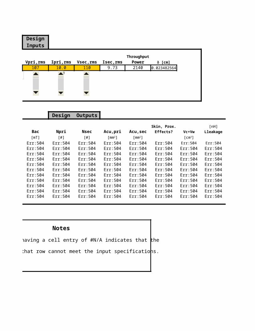
DesignInputs
Throughput
Material Vpri,rms Ipri,rms Vsec,rms Isec,rms Power3C94 107 10.0 110 9.73 2140 0.023482564
100
Design Outputs
Skin, Prox.Jrms Bac Npri Nsec Acu,pri Acu,sec Effects?
[mT] [#] [#]Err:504 Err:504 Err:504 Err:504 Err:504 Err:504 Err:504Err:504 Err:504 Err:504 Err:504 Err:504 Err:504 Err:504Err:504 Err:504 Err:504 Err:504 Err:504 Err:504 Err:504Err:504 Err:504 Err:504 Err:504 Err:504 Err:504 Err:504Err:504 Err:504 Err:504 Err:504 Err:504 Err:504 Err:504Err:504 Err:504 Err:504 Err:504 Err:504 Err:504 Err:504Err:504 Err:504 Err:504 Err:504 Err:504 Err:504 Err:504Err:504 Err:504 Err:504 Err:504 Err:504 Err:504 Err:504Err:504 Err:504 Err:504 Err:504 Err:504 Err:504 Err:504Err:504 Err:504 Err:504 Err:504 Err:504 Err:504 Err:504Err:504 Err:504 Err:504 Err:504 Err:504 Err:504 Err:504
Notes
Any row having a cell entry of #N/A indicates that the
core in that row cannot meet the input specifications.
d [cm]
[A/mm2] [mm2] [mm2]

[nH]Vc+Vw Lleakage Efficiency
[%]Err:504 Err:504 Err:504Err:504 Err:504 Err:504Err:504 Err:504 Err:504Err:504 Err:504 Err:504Err:504 Err:504 Err:504Err:504 Err:504 Err:504Err:504 Err:504 Err:504Err:504 Err:504 Err:504Err:504 Err:504 Err:504Err:504 Err:504 Err:504Err:504 Err:504 Err:504
[cm3]
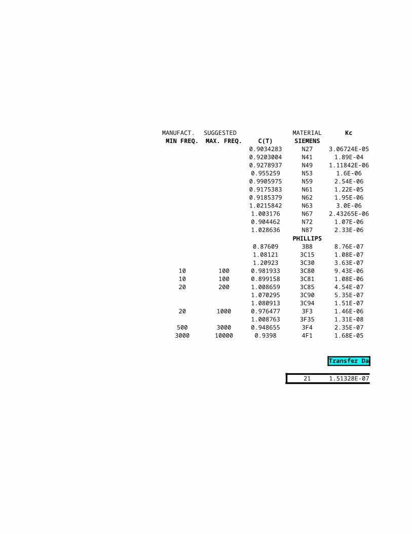
MANUFACT. SUGGESTED MATERIALMIN FREQ. MAX. FREQ. C(T) SIEMENS
0.9034283 N270.9203004 N410.9278937 N490.955259 N530.9905975 N590.9175383 N610.9185379 N621.0215842 N631.003176 N670.904462 N721.028636 N87
PHILLIPS0.87609 3B81.08121 3C151.20923 3C30
10 100 0.981933 3C8010 100 0.899158 3C8120 200 1.008659 3C85
1.070295 3C901.080913 3C94
20 1000 0.976477 3F31.008763 3F35
500 3000 0.948655 3F43000 10000 0.9398 4F1
21

Kc a b
3.067241E-05 1 2.451.89E-04 1 2.14
1.118424E-06 1 2.981.6E-06 1 2.860
2.54E-06 1 2.95111.22E-05 1 2.5851.95E-06 1 2.7133.0E-06 1 2.714
2.432649E-06 1 2.7561.07E-06 1 2.8652.33E-06 1 2.76
8.76E-07 1.6 2.51.08E-07 1.7 2.83.63E-07 1.5 2.79.43E-06 1.42 2.21.08E-06 1.56 2.554.54E-07 1.6 2.65.35E-07 1.5 2.61.51E-07 1.6 2.71.46E-06 1.3 2.51.31E-08 1.5 3.452.35E-07 1.35 3.091.68E-05 1.35 2.25
Transfer Data
1.513278E-07 1.6 2.7

Transfer Data
Core Rating Core #
Err:504 Err:504 Phillips Designation (mm) (mm) (mm)Criteria Err:504 Core Type/NumberDim. A Dim. B Dim. C
TestE Lleakage E5.3/2.7/2 5.25 2.65 2Err:504 E6.3/2.9/2 6.3 2.9 2
0 Pwr Loss E13/6/6 12.7 5.7 6.4Err:504 E13/7/4 12.95 6.5 3.7
Jrms Bpeak E/16/8/5 16 8.2 4.7Err:504 Err:504 E19/8/5 19.05 8.05 8.7
E19/8/9 19.1 8.1 8.7Acore Vc + Vw E20/10/5 20.7 10 5.3Err:504 Err:504 E20/10/6 20 7 5.9
E25/9/6 25.4 9.45 6.3E25/10/6 25.4 9.65 6.35E25/13/7 25 12.8 7.5E25/16/6 25.4 15.85 6.3E30/15/7 30.8 15 7.3E30/15/13 30.8 15.2 12.6E31/13/9 30.9 13.1 9.4E32/16/9 32 16.4 9.5E34/14/9 34.3 14.1 9.3E36/21/15 36 21.8 15.5E41/17/12 40.6 16.6 12.4E42/21/15 43 21 15.2E42/21/20 43 21 20E42/33/20 42 32.8 20E46/23/30 46 23.2 30E47/20/16 46.9 19.6 15.6E50/27/15 50 27.2 14.6E55/28/21 56.2 27.8 21E55/28/25 56.6 27.8 25E56/24/19 56.1 23.6 18.8E65/32/27 65 32.8 27.4E71/33/32 70.5 33.2 32E80/38/20 80 38.1 19.8
E Core Dimensions
A
B C
D
EF

No coil former : lw = 2(F+C)+0.5π(E-F)
As = surface area of assembled core plus surface area of winding not included in core surface area.
Core surface area = 4AB + 4BC + 2AC
Mean turn length = lw
Winding Volume Vw = Awlw
Surface Area of assembled transformer
A
B C
D
EF
C
F
(E-F)14
radius =

Surface area of winding not included in core surface area =4E{0.5}(E-F)+ 4{2D(0.5)(E-F)} = 2E(E-F) + 4D(E-F) = 2(E-F)(E+2D)
As = 4AB + 4BC + 2AC + 2(E-F)(E+2D)
2B C
(E-F)1
2
Rounded corners ignored in surface area estimate
A
A
E
2D
(E-F)1
2

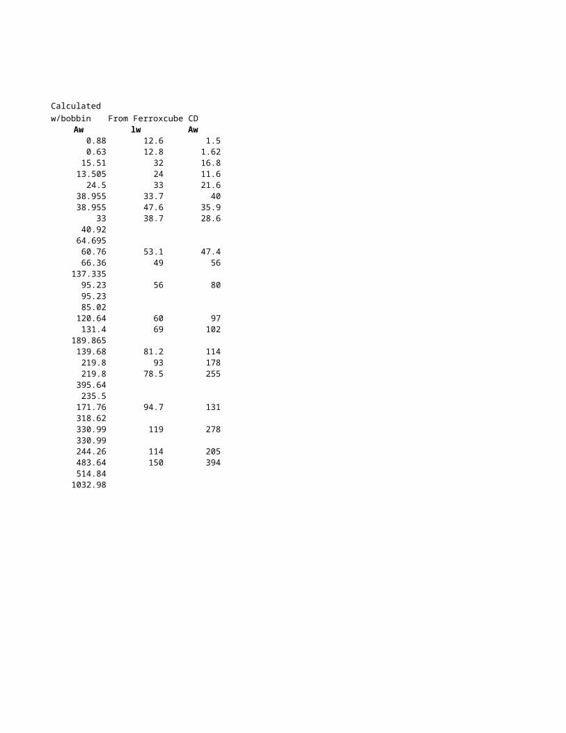
Calculatedw/bobbin
(mm) (mm) (mm) (mm) (mm)Dim. D Dim. E Dim. F Lm Ac Vc Lw
1.9 3.8 1.4 12.3 2.8 34.4 14.51.85 3.6 1.4 13.8 2.8 38.7 14.14.1 9.5 3.2 27.7 20.5 567.8 33.04.5 8.95 3.7 29.5 13.7 404.3 26.95.7 11.3 4.7 36.8 22.1 812.4 33.15.7 14.3 4.75 39.8 41.3 1645.0 45.85.7 14.3 4.75 39.9 41.3 1648.3 45.86.3 12.8 5.2 45.2 27.6 1245.8 36.87 14.1 5.9 45.5 34.8 1582.6 40.4
6.5 19.3 6.35 48.5 40.0 1941.3 49.56.4 18.8 6.35 48.4 40.3 1952.1 48.88.7 17.5 7.5 56.6 56.3 3182.3 49.6
12.9 19.3 6.35 74.1 40.0 2965.5 49.59.7 19.5 7.2 68.8 52.6 3618.3 52.29.7 19.5 7.2 68.8 90.7 6245.3 62.88.6 21.9 9.4 61.0 88.4 5392.6 61.1
11.2 22.7 9.5 72.6 90.3 6552.2 62.69.8 25.5 9.3 69.2 86.5 5986.5 66.5
15.75 24.5 10.2 95.4 158.1 15075.6 77.710.4 28.6 12.45 76.6 154.4 11824.0 78.914.8 29.5 12.2 97.7 185.4 18116.6 85.814.8 29.5 12.2 97.7 244.0 23837.6 95.426 29.5 12.2 140.9 244.0 34385.7 95.4
15.8 31.5 14.2 103.3 426.0 43990.9 119.412.1 32.4 15.6 88.0 243.4 21407.2 92.718.6 34.1 14.6 118.9 213.2 25336.8 92.918.5 37.5 17.2 123.7 361.2 44665.6 112.218.5 37.5 17.2 124.3 430.0 53443.4 120.214.6 38.1 18.8 106.0 353.4 37450.5 109.422.2 44.2 20 145.7 548.0 79819.5 136.721.9 48 22 148.9 704.0 104843.2 152.728.2 59.1 19.8 184.9 392.0 72493.3 144.8
(mm2) (mm3)
2D
(E-F)1
2
radius = 1
2(A - E)

With coil former lw = 2(F+C+3.2mm)+0.5π(E-F-1.6mm)
As = surface area of assembled core plus surface area of winding not included in core surface area.
Core surface area = 4AB + 4BC + 2AC
Surface Area of assembled transformer As
2D
(E-F)1
2
radius = 1
2(A - E)

Surface area of winding not included in core surface area =4E{0.5}(E-F)+ 4{2D(0.5)(E-F)} = 2E(E-F) + 4D(E-F) = 2(E-F)(E+2D)
As = 4AB + 4BC + 2AC + 2(E-F)(E+2D)
2B C
(E-F)1
2
Rounded corners ignored in surface area estimate
A
A
E
2D
(E-F)1
2

Calculatedw/bobbin
[mT] @ freq.Aw Vw As Jrms Bpeak
0.9 12.7 134.3 992.6 1476 10.0 325.10.6 8.9 153.6 868.1 1668 10.6 340.1
15.5 511.5 821.1 162.4 394 5.2 199.213.5 363.7 717.2 185.9 483 5.7 215.024.5 809.7 1129.0 118.1 360 4.9 192.839.0 1783.4 1715.9 77.7 259 4.2 170.639.0 1783.4 1723.9 77.3 260 4.2 170.933.0 1215.1 1645.5 81.0 346 4.8 189.940.9 1651.6 1422.0 93.8 228 3.9 162.664.7 3203.7 2354.9 56.6 237 4.0 165.160.8 2967.2 2335.0 57.1 246 4.1 167.366.4 3290.7 2737.0 48.7 219 3.9 160.3
137.3 6800.8 3497.9 38.1 185 3.5 150.795.2 4970.9 3692.6 36.1 222 3.9 161.395.2 5980.3 4371.8 30.5 185 3.5 150.685.0 5195.8 3670.1 36.3 179 3.5 148.9
120.6 7553.5 4521.0 29.5 166 3.4 144.7131.4 8741.0 4558.3 29.3 160 3.3 142.8189.9 14759.9 7208.4 18.5 125 2.9 130.3139.7 11026.8 6121.7 21.8 139 3.1 135.4219.8 18869.6 8240.9 16.2 115 2.8 126.4219.8 20979.7 9056.9 14.7 105 2.7 121.9395.6 37763.4 12634.3 10.6 91 2.5 115.6235.5 28130.2 11996.1 11.1 86 2.4 113.5171.8 15916.0 8265.0 16.1 115 2.8 126.1318.6 29600.8 11269.2 11.8 106 2.7 122.6331.0 37123.5 13969.7 9.5 88 2.4 114.6331.0 39771.4 14928.6 8.9 83 2.4 111.9244.3 26719.4 11777.7 11.3 95 2.5 117.7483.6 66104.9 19973.1 6.7 71 2.2 105.6514.8 78620.2 22897.6 5.8 65 2.1 102.0
1033.0 149564.1 27455.8 4.9 64 2.1 101.7
(mm2) (mm3) (mm2) [∞C/W] [mW/cm3] [A/mm2]Rq Psp @ DT
Magnetic path length lm = 4D +(E-F) + (0.5)π(A-E)
2D
(E-F)1
2
radius = 1
2(A - E)

As = surface area of assembled core plus surface area of winding not included in core surface area.
Core Area Ac = FC
Core Volume Vc = Aclm = FC(4D +(E-F) + πE)
2D
(E-F)1
2
radius = 1
2(A - E)

[watts] [#] [nH] [watts]E_rating Npri Lleakage Pwr Loss
2.4 262.08 13127.98 0.071.9 250.49 11044.69 0.08
97.4 58.46 1812.58 0.4267.8 81.06 2160.58 0.37153.6 56.01 1256.70 0.58342.8 33.83 918.87 0.89343.9 33.78 916.34 0.89249.2 45.57 965.29 0.85271.0 42.14 878.63 0.74509.9 36.12 1347.45 1.22498.2 35.36 1243.16 1.21686.4 26.46 417.55 1.42874.4 39.56 814.19 1.81933.8 28.14 548.58 1.91
1373.0 17.45 253.92 2.261162.0 18.13 305.54 1.901573.1 18.27 257.84 2.341592.8 19.31 429.33 2.363391.3 11.58 99.08 3.732665.4 11.41 167.18 3.174291.5 10.17 108.72 4.265186.7 8.02 75.06 4.698241.7 8.45 47.51 6.548189.9 4.94 33.34 6.214377.5 7.77 81.30 4.286654.3 9.13 84.91 5.839987.7 5.76 42.79 7.2311242.2 4.96 33.93 7.737678.2 5.74 49.79 6.0918259.8 4.12 26.52 10.3423043.9 3.32 20.94 11.8525538.2 5.99 75.66 14.21

Calculated Calculated
w/bobbin w/bobbin From Ferroxcube CDlw Aw lw Aw
14.456 0.88 12.6 1.514.142 0.63 12.8 1.6232.979 15.51 32 16.8
26.9305 13.505 24 11.633.05 24.5 33 21.6
45.7815 38.955 33.7 4045.7815 38.955 47.6 35.9
36.82 33 38.7 28.640.362 40.92
49.5195 64.69548.8345 60.76 53.1 47.449.588 66.36 49 56
49.5195 137.33552.199 95.23 56 8062.799 95.2361.113 85.0262.612 120.64 60 9766.522 131.4 69 10277.739 189.865
78.9435 139.68 81.2 11485.849 219.8 93 17895.449 219.8 78.5 25595.449 395.64
119.449 235.592.664 171.76 94.7 13192.903 318.62
112.159 330.99 119 278120.159 330.99109.389 244.26 114 205136.682 483.64 150 394152.708 514.84144.789 1032.98
Transfer DataPhillips
Core Rating Core # designation [mm] [mm] [mm]Err:504 Err:504 Core # Dim. A Dim. B Dim. CCriteria Err:504 EC35 35.3 17.3 9.5TestEC Lleakage EC41 41.6 19.5 11.6
Err:504 EC52 52.2 24.2 13.41 Pwr Loss EC70 71.7 34.5 16.4
Err:504Jrms Bpeak
Err:504 Err:504
Acore Vc + VwErr:504 Err:504

[mm] [mm] [mm] [mm] [mm]Dim. D Dim. E Dim. H Lm Ac Vc Lw
22.8 9.5 12.3 77.4 84.3 6530 53.127.1 11.6 13.9 89.3 121 10800 62.433 13.4 15.9 105 180 18800 74.9
44.5 16.4 22.8 144 279 40100 97.3
EC Core Formulas
Winding parameters:
lw = 0.5π (D + E+1.6) ; with coil former having walls 0.8 mm thick
Aw = (D-E-1.6)(H-0.8) ; with bobbin having walls 0.8 mm thick
Exposed core surface area:Front and back = 2(A2B) - 2(2HD) = 4AB - 4DHTop and bottom = 2ACLeft and right = 2(2BC) = 4BCTotal exposed core surface area = 4AB - 4DH + 2AC + 4BC
Exposed winding surface area:Vertical surface = 2HπD - 2(2HC)Horizontal surface = 2π(0.5D)2 - 2CD
As = 4B(A+C) + 2AC - 4DH + 2H(πD - 2C) + 0.5πD2 - 2CD
[mm2] [mm3]
Magnetic parameters (mean path length lm, core area Ac, and core volume Vc) given in manufacturer's catalog.
Mean turn length lw = 2π (D/2 + E/2)/2 = 0.5π (D + E) ; No coil former
Winding window area Aw = 2H (D-E)/2 = (D-E)H ; no bobbin
Winding volume Vw = Awlw = π (D + E) H (D-E) = π (D2 - E2)
Surface area of assembled core and winding As

Ferroxcube Ferroxcubew/bobbin w/bobbin
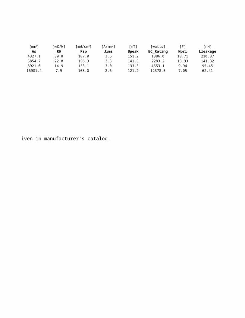
[mT]Aw Vw As Psp Jrms Bpeak
102.5 5442.8 4327.1 30.8 187.0 3.6 151.2137.5 8580.0 5854.7 22.8 156.3 3.3 141.5212.0 15878.8 8921.0 14.9 133.1 3.0 133.3465.0 45244.5 16981.4 7.9 103.0 2.6 121.2
[mm2] [mm3] [mm2] [∞C/W] [mW/cm3] [A/mm2]Rq
(mean path length lm, core area Ac, and core volume Vc) given in manufacturer's catalog.

[watts] [#] [nH] [watts]EC_Rating Npri Lleakage Pwr Loss
1386.0 18.71 210.37 2.242283.2 13.93 141.32 3.034553.1 9.94 95.45 4.6212378.5 7.05 62.41 8.79

Calculated Calculated Ferroxcube Ferroxcube
w/bobbin w/bobbin w/bobbin w/bobbinLw Aw Lw Aw
53.2 134.6 53.1 102.563.3 182.1 62.4 137.575.4 271.8 74.9 212.098.1 583.0 97.3 465.0
Calculated Calculated
No bobbin No bobbinLw Aw
50.7 163.660.8 215.572.8 311.695.6 640.7

Transfer DataPhillips
Core Rating Core # designation [mm] [mm] [mm]Err:504 Err:504 Core # Dim. A Dim. B Dim. CCriteria Err:504 EFD10 10.5 5.2 2.7TestEFD Lleakage EFD12 12.5 6.2 3.5
Err:504 EFD15 15.0 7.5 4.70 Pwr Loss EFD20 20.0 10.0 6.7
Err:504 EFD25 25.0 12.5 9.1Jrms Bpeak EFD30 30.0 15.0 9.1
Err:504 Err:504
Acore Vc + VwErr:504 Err:504

[mm] [mm] [mm] [mm] [mm]Dim. D Dim. E Dim. F Dim. H Lm Ac Vc
7.7 4.6 1.5 3.8 23.7 7.2 171.09.0 5.4 2.0 4.6 28.5 11.4 325.0
11.0 5.3 2.4 5.5 34.0 15.0 510.015.4 8.9 3.6 7.7 47.0 31.0 1460.018.7 11.4 5.2 9.3 57.0 58.0 3300.022.4 14.6 4.9 11.2 68.0 69.0 4700.0
EFD Core Formulas
Winding parameters:
lw = 2(E+F) +2π(0.25)(D - E) = 2(E+F) +0.5π(D-E) ; no coil former
lw = = 2(E+F+3.2 ) +0.5π(D-E-1.6) ; with coil former having wall thickness 0.8 mm
Aw = (D-E-1.6)(H-.8) ; with coil former having wall thickness 0.8 mm
[mm2] [mm3]
Magnetic parameters (mean path length lm, core area Ac, and core volume Vc) given in manufacturer's catalog.
Mean turn length lw
Winding window area Aw = 2H (D-E)/2 = (D-E)H : no coil former

Exposed core surface area:Front and back = 2(A2B) - 2(2HD) = 4AB - 4DHTop and bottom = 2ACLeft and right = 2(2BC) = 4BCTotal exposed core surface area = 4AB - 4DH + 2AC + 4BC
Exposed winding surface area:Vertical surface = 2πDH - 4CH
Horizontal surface = 4(D-E)E + 4F(D-E) +2EF +2π(D-E)2 - 2DC
Total surface area As = 2H(πD-2C) + 4(D-E)(E+F) + 2EF +2π(D-E)2 - 2CD
= 4(D-E)(E+F) + 2EF +2π(D-E)2 - 2CD
Winding volume Vw = Awlw
Surface area of assembled core and winding As

Ferroxcube Ferroxcubew/bobbin w/bobbin
[mm]Lw Aw Vw As Psp Jrms
14.8 4.2 62.2 251.0 531.1 557.2 6.118.6 6.5 120.9 342.3 389.5 397.3 5.225.6 16.7 427.5 578.5 230.5 319.3 4.734.1 27.7 944.6 986.9 135.1 212.4 3.840.0 46.0 1840.0 1352.0 98.6 136.1 3.052.9 52.3 2766.7 1894.7 70.4 131.3 3.0
lw = 2(E+F) +2π(0.25)(D - E) = 2(E+F) +0.5π(D-E) ; no coil former
lw = = 2(E+F+3.2 ) +0.5π(D-E-1.6) ; with coil former having wall thickness 0.8 mm
Aw = (D-E-1.6)(H-.8) ; with coil former having wall thickness 0.8 mm
[mm2] [mm3] [mm2] [∞C/W] [mW/cm3] [A/mm2]Rq
(mean path length lm, core area Ac, and core volume Vc) given in manufacturer's catalog.
Aw = 2H (D-E)/2 = (D-E)H : no coil former

Horizontal surface = 4(D-E)E + 4F(D-E) +2EF +2π(D-E)2 - 2DC
Total surface area As = 2H(πD-2C) + 4(D-E)(E+F) + 2EF +2π(D-E)2 - 2CD

[mT] [watts] [#] [nH] [watts]Bpeak EFD_Rating Npri Lleakage Pwr Loss226.6 12.5 146.21 2701.37 0.13199.9 22.9 104.67 1669.10 0.18184.4 64.0 86.25 2065.81 0.30158.5 153.9 48.54 709.81 0.51134.4 324.6 30.59 307.51 0.70132.7 425.5 26.06 261.82 0.98
Calculated Calculated Ferroxcube
w/bobbin w/bobbin w/bobbinLw Aw Lw
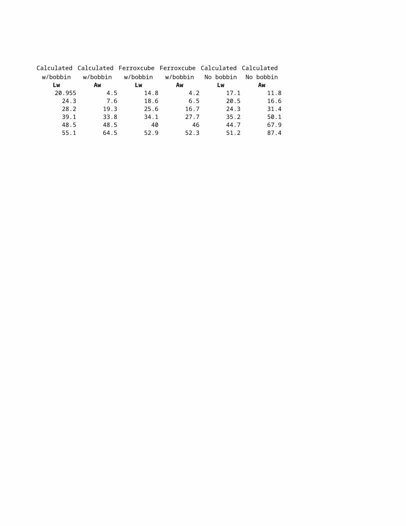
20.955 4.5 14.824.3 7.6 18.628.2 19.3 25.639.1 33.8 34.148.5 48.4 4055.1 64.5 52.9

Ferroxcube Calculated Calculated
w/bobbin No bobbin No bobbinAw Lw Aw
4.2 17.1 11.86.5 20.5 16.6
16.7 24.3 31.427.7 35.2 50.1
46 44.7 67.952.3 51.2 87.4
Transfer DataPhillips
Core Rating Core # designation [mm] [mm] [mm]Err:504 Err:504 Core # Dim. A Dim. B Dim. CCriteria Err:504 EP7 9.4 7.5 5.0TestEP Lleakage EP10 11.5 10.2 7.4
Err:504 EP13 12.8 13.0 9.00 Pwr Loss EP17 18.0 16.8 11.4
Err:504 EP20 24.0 21.4 14.4Jrms Bpeak
Err:504 Err:504
Acore Vc + VwErr:504 Err:504
Core dimensions:

[mm] [mm] [mm] [mm] [mm]Dim. D Dim. E Dim. F Dim. G Lm Ac Vc
6.5 7.2 3.4 1.7 15.5 10.7 165.07.6 9.4 3.3 1.8 19.3 11.3 215.09.0 9.7 4.5 2.4 24.2 19.5 472.0
11.0 12.0 5.7 3.3 29.5 33.7 999.015.0 16.5 8.8 4.5 41.1 78.7 3230.0
EP Core Formulas
Mean turn length lw = 2π(E+F)/2 = π(E + F) ; no bobbin
lw = π(E + F+1.6) ; bobbin with 0.8 mm thick wallsWinding window area Aw = C(E-F)/2 ; no bobbinAw = (C-1.6)(E-F-1.6)/2 ; bobbin with 0.8 mm thick walls
Winding volume Vw = lw Aw
Exposed core surface:
Vertical surface area = 2BD + AB + AB - EC = 2B(D+A) - ECTop and bottom surface = 2ADExposed core surface area = 2AD + 2B(A+D) - EC
Exposed winding surface = CπE/2
Total surface area = 2AD + 2B(A+D) - EC + 0.5πCE = 2AD + 2B(A+D) + 0.57CE
[mm2] [mm3]
Magnetic dimensions (lm, Ac, Vc) given on core spec sheets.Winding dimensions:
Surface area As:

Ferroxcube Ferroxcubew/bobbin w/bobbin
[mm]Lw Aw Vw As Psp Jrms
17.7 4.3 76.1 381.2 349.8 818.2 7.521.7 11.4 247.4 604.1 220.7 676.1 6.823.0 13.5 310.5 847.0 157.4 560.1 6.228.9 18.6 537.5 1448.4 92.1 487.8 5.840.8 33.6 1370.9 2524.6 52.8 284.0 4.4
Total surface area = 2AD + 2B(A+D) - EC + 0.5πCE = 2AD + 2B(A+D) + 0.57CE
[mm2] [mm3] [mm2] [∞C/W] [mW/cm3] [A/mm2]Rq

[mT] [watts] [#] [nH] [watts]Bpeak EP_Rating Npri Lleakage Pwr Loss261.2 26.7 85.33 2050.50 0.20243.4 63.2 86.72 2815.91 0.31227.0 109.7 53.88 807.56 0.44215.7 231.6 32.81 360.00 0.75176.5 610.1 17.17 134.63 1.31

Calculated Calculated Ferroxcube
w/bobbin w/bobbin w/bobbinLw Aw Lw
19.2 3.7 17.722.5 13.1 21.724.8 13.3 23.030.3 23.0 28.942.2 39.0 40.8

Ferroxcube Calculated Calculated
w/bobbin No bobbin No bobbinAw Lw Aw
4.3 16.6 9.511.4 19.9 22.613.5 22.3 23.418.6 27.8 35.933.6 39.7 55.4

Transfer DataPhillips
Core Rating Core # designation [mm] [mm] [mm]Err:504 Err:504 Core # Dim. A Dim. B Dim. CCriteria Err:504 ER9.5 9.5 5.0 2.5TestER Lleakage ER11 11.0 6.0 2.5
Err:504 ER14.5 14.5 6.8 3.00 Pwr Loss ER28 28.6 11.4 14.0
Err:504 ER28L 28.6 11.4 16.9Jrms Bpeak ER35 35.0 11.4 20.7
Err:504 Err:504 ER40 40.0 13.4 22.4ER42 42.0 15.6 22.4
Acore Vc + Vw ER42A 42.0 15.6 21.8Err:504 Err:504 ER48 48.0 21.0 21.2
ER54 53.5 18.0 18.3

[mm] [mm] [mm] [mm] [mm]Dim. D Dim. E Dim. F Dim. G Lm Ac Vc
7.1 3.5 1.6 7.5 14.2 8.5 120.08.0 4.3 1.5 8.7 14.7 11.9 174.0
11.8 4.8 1.6 11.8 19.0 17.6 333.021.8 9.9 9.8 21.8 64.0 81.4 5260.021.8 9.9 12.7 21.8 75.5 81.4 6140.026.2 11.3 14.8 26.2 90.8 107.0 9710.029.6 13.3 15.5 29.6 98.0 149.0 14600.030.1 15.5 15.5 30.1 98.8 194.0 19200.030.4 15.0 15.6 30.4 99.0 170.0 16800.038.0 18.0 14.7 38.0 100.0 255.0 25500.040.7 17.9 11.1 40.7 91.8 250.0 23000.0
ER Core Formulas
lw = π(G+E+1.6) ; bobbin with 0.8 mm thick walls
Aw = (F-0.8)(G-E-1.6) ; bobbin with 0.8 mm thick walls
Surface area As:Exposed core surface: front and back = 2(2CA) - 2(2FD) = 4AC-4DFLeft and right = 2(2CB) = 4BCtop and bottom = 2ABTotal exposed core surface = 4AC -4DF+4BC+2AB = 4C(A+B)+2AB-4DF
Winding surface:
[mm2] [mm3]
Magnetic dimensions (mean path length lm, core area Ac, and core volume Vc) given on core specification sheets.
Winding dimensions:
Mean turn length lw = 2π (G+E)/2 = π(G+E) ; no bobbin
Winding area Aw = 2F(G-E)/2 = F(G-E) ; no bobbin
Winding Volume Vw = lwAw = πF(G2 - E2)

Vertical surface = πG2F - 2(2FB) = 2πFG - 4BFHorizontal surface = 2π(G/2)2 - 2BGTotal winding surface = 2πFG-4BF + 0.5πG2 -2BG = πG(2F-0.5G) - 2B(2F+G)
As = 4C(A+B)+2AB-4DF + πG(2F-0.5G) - 2B(2F+G)

Calculated Calculated Calculatedw/bobbin w/bobbin w/bobbin
[mm]Lw Aw Vw As Psp Jrms
19.8 1.9 38.0 71.7 1859.6 234.9 4.022.9 2.0 44.9 76.7 1738.3 181.3 3.528.6 4.3 123.4 73.2 1821.8 83.0 2.452.3 92.7 4846.4 1689.4 78.9 86.5 2.452.3 122.6 6408.1 2165.5 61.6 89.3 2.561.4 186.2 11430.3 3174.7 42.0 77.7 2.369.9 216.1 15097.1 3903.8 34.2 68.0 2.174.1 191.1 14161.3 4207.1 31.7 65.3 2.173.8 204.2 15070.9 4042.3 33.0 65.6 2.190.4 255.8 23128.9 4043.6 33.0 43.0 1.794.5 218.4 20638.1 3324.9 40.1 39.4 1.6
Exposed core surface: front and back = 2(2CA) - 2(2FD) = 4AC-4DF
Total exposed core surface = 4AC -4DF+4BC+2AB = 4C(A+B)+2AB-4DF
[mm2] [mm3] [mm2] [∞C/W] [mW/cm3] [A/mm2]Rq
(mean path length lm, core area Ac, and core volume Vc) given on core specification sheets.

Total winding surface = 2πFG-4BF + 0.5πG2 -2BG = πG(2F-0.5G) - 2B(2F+G)

[mT] [watts] [#] [nH] [watts]Bpeak ER_Rating Npri Lleakage Pwr Loss164.5 3.2 170.54 15055.51 0.04149.5 3.6 134.07 12650.59 0.04111.9 6.0 121.09 19184.72 0.04113.7 618.7 25.78 441.63 0.87115.0 841.1 25.48 332.83 1.12109.2 1488.0 20.41 269.37 1.64104.0 2141.6 15.40 182.26 2.02102.4 2378.4 12.01 105.33 2.18102.6 2238.7 13.67 142.55 2.0987.8 2911.9 10.66 146.30 2.0985.0 2258.8 11.23 256.23 1.72

Calculated Calculated Ferroxcube
w/bobbin w/bobbin w/bobbinLw Aw Lw
19.8 1.9 18.422.9 2.0 21.628.6 4.3 27.052.3 92.752.3 122.661.4 186.269.9 216.174.1 191.173.8 204.290.4 255.894.5 218.4

Ferroxcube Calculated Calculated
w/bobbin No bobbin No bobbinAw Lw Aw
2.8 17.3 6.42.8 20.4 6.65.1 26.1 11.2
49.8 116.649.8 151.158.9 220.567.4 252.771.6 226.371.3 240.287.9 294.092.0 253.1

Transfer DataPhillips
Core Rating Core # designation [mm] [mm] [mm]Err:504 Err:504 Core # Dim. A Dim. B Dim. CCriteria Err:504 ETD29 30.6 15.8 9.8TestETD Lleakage ETD34 35 17.3 11.1
Err:504 ETD39 40 19.8 12.81 Pwr Loss ETD44 45 22.3 15.2
Err:504 ETD49 49.8 24.7 16.7Jrms Bpeak ETD54 54.5 27.6 18.9
Err:504 Err:504 ETD59 59.8 31 21.65
Acore Vc + VwErr:504 Err:504
ETD Core Formulas
lw = 0.5π(E+F+1.6) ; bobbin with 0.8 mm thick walls
Aw = (D-0.8)(E-F-1.6) ; bobbin with 0.8 mm thick walls
Exposed core surface:left and right = C4B : top and bottom 2CA : front and back 2(2AB-2DE)Summing 4BC + 2AC+4AB-4DE
Exposed winding surface:Vertical cylindrical surface = 2D*2πE/2 - 2(2DC) = 2πDE - 4CDHorizontal circuilar surfaces = 2π(0.25E2) - 2CE = 0.5π(E2) - 2CE
Summing exposed core and winding area:As = 4BC+2AC+4AB-4DE+2πDE-4CD+0.5π(E2)-2CE
Mean turn length lw =2π (E+F)/4 = 0.5π(E+F) ; no bobbin
Winding window area Aw = 2D = D(E-F) ; no bobbin
Winding volume Vw = {0.25 πE2 - 0.25πF2]2D = 0.5πD(E2 - F2)
Surface Area As

Ferroxcubew/bobbin
[mm] [mm] [mm] [mm] [mm]Dim. D Dim. E Dim. F Lm Ac Vc Lw
11 22 9.8 72 76 5470 52.011.8 25.6 11.1 78.6 97.1 7640 60.014.2 29.3 12.8 92.2 125 11500 69.016.1 32.5 15.2 103 173 17800 77.017.7 36.1 16.7 114 211 24000 85.020.2 41.2 18.9 127 280 35500 96.022.5 44.7 21.65 139 368 51500 106.0
Dimensions
[mm2] [mm3]

Ferroxcube Ferroxcubew/bobbin w/bobbin
[mT]Aw Vw As Psp Jrms Bpeak
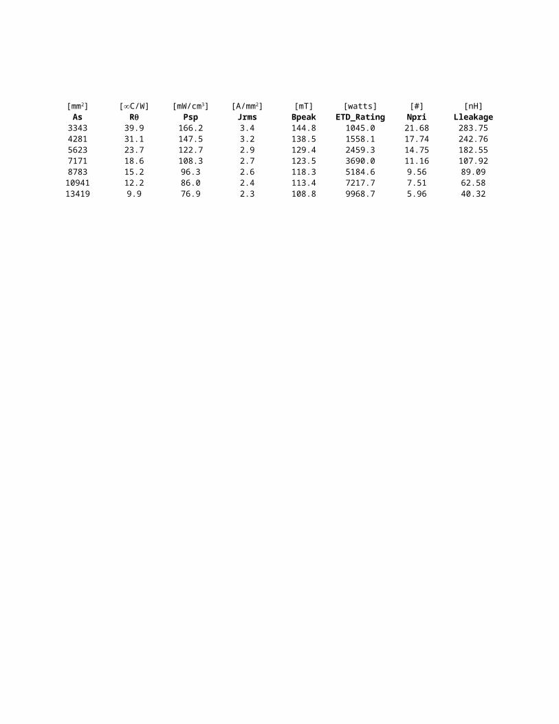
95.0 4940.0 3343 39.9 166.2 3.4 144.8123.0 7380.0 4281 31.1 147.5 3.2 138.5177.0 12213.0 5623 23.7 122.7 2.9 129.4214.0 16478.0 7171 18.6 108.3 2.7 123.5273.0 23205.0 8783 15.2 96.3 2.6 118.3316.0 30336.0 10941 12.2 86.0 2.4 113.4366.0 38796.0 13419 9.9 76.9 2.3 108.8
[mm2] [mm3] [mm2] [∞C/W] [mW/cm3] [A/mm2]Rq

[watts] [#] [nH] [watts]ETD_Rating Npri Lleakage Pwr Loss
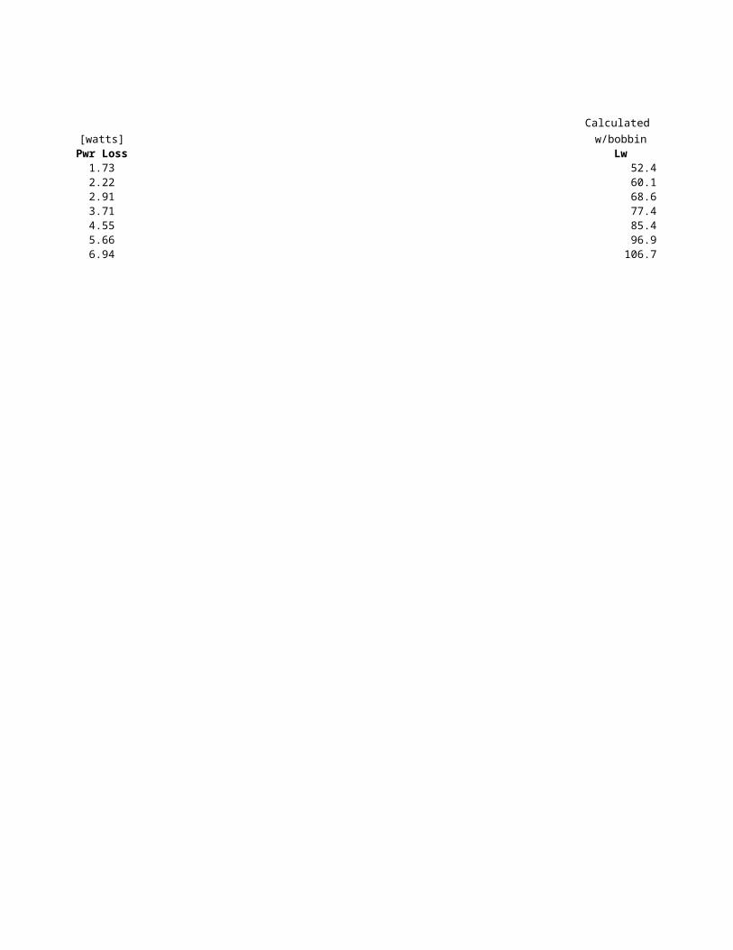
1045.0 21.68 283.75 1.731558.1 17.74 242.76 2.222459.3 14.75 182.55 2.913690.0 11.16 107.92 3.715184.6 9.56 89.09 4.557217.7 7.51 62.58 5.669968.7 5.96 40.32 6.94
Calculated Calculated Ferroxcube Ferroxcube
w/bobbin w/bobbin w/bobbin w/bobbinLw Aw Lw Aw
52.4 108.1 52.0 95.060.1 141.9 60.0 123.068.6 199.7 69.0 177.077.4 240.2 77.0 214.085.4 300.8 85.0 273.096.9 401.6 96.0 316.0
106.7 465.5 106.0 366.0
Calculated Calculated
No bobbin No bobbinLw Aw
49.9 134.257.6 171.166.1 234.374.9 278.582.9 343.494.4 450.5
104.2 518.6

Transfer DataSeimens
Core Rating Core # Designation [mm] [mm] [mm]Err:504 Err:504 Core # Dim. A Dim. B Dim. CCriteria Err:504 PM 50/39 49.2 38.8 23.4TestPM Lleakage PM 62/49 62.0 49.0 -
Err:504 PM 74/59 74.0 59.0 -1 Pwr Loss PM 87/70 87.0 70.0 -
Err:504 PM 114/93 114 93 -Jrms Bpeak
Err:504 Err:504
Acore Vc + VwErr:504 Err:504
PM Core Forumlas
Effective magnetic length lm, core area Ac, and core volume Vm given in core specification sheet.

Mean winding length lw = 2π(g +h)/2 = π(g + h) ; no bobbinlw = = π(g + h + 1.6) ; bobbin with 0.8 thick walls
Winding window area Aw = d(h - g)/2 ; no bobbinAw = (d - 1.6)(h - g -1.6)/2 ; bobbin with 0.8 mm thick walls
Winding volume = Vw = lwAw = π(h^2 - g^2)/2
Surface area As ≈ 2π (a/2)^2 + 2π(a/2)h = πa^2/2 + πah

[mm] [mm] [mm] [mm] [mm] [mm] [mm] Dim. D Dim. E Dim. F Dim. G Dim. H Dim. I Dim. J
26.8 4.8 1.4 19.7 39.7 5.4 37.633.4 - - 25.5 48.8 5.4 -40.7 - - 29.5 57.5 5.4 -48.0 - - 31.7 67.1 8.5 -63 - - 43 88 5.4 -
Effective magnetic length lm, core area Ac, and core volume Vm given in core specification sheet.

Mean winding length lw = 2π(g +h)/2 = π(g + h) ; no bobbinlw = = π(g + h + 1.6) ; bobbin with 0.8 thick walls
Winding window area Aw = d(h - g)/2 ; no bobbinAw = (d - 1.6)(h - g -1.6)/2 ; bobbin with 0.8 mm thick walls
Winding volume = Vw = lwAw = π(h^2 - g^2)/2
Surface area As ≈ 2π (a/2)^2 + 2π(a/2)h = πa^2/2 + πah

Calculated Calculated Calculatedw/bobbin w/bobbin w/bobbin
[mm] [mm]Lm Ac Vc Lw Aw Vw As84 370 31000 191.5 231.8 44406.6 13734.0109 570 62000 238.3 345.0 82229.6 21570.5128 790 101000 278.2 516.1 143586.6 30555.3146 910 133000 315.3 784.2 247211.1 42097.0200 1720 344000 416.4 1332.4 554755.1 72307.9
[mm2] [mm3] [mm2] [mm3] [mm2]

[mT] [watts] [#] [nH]Psp Jrms Bpeak PM_Rating Npri Lleakage
9.7 94.3 2.5 117.3 7578.3 5.49 90.336.2 77.4 2.3 109.1 14636.1 3.84 51.234.4 64.6 2.1 102.0 25944.8 2.96 35.083.2 57.3 2.0 97.6 40877.7 2.69 35.121.8 41.6 1.7 86.7 99424.2 1.60 15.93
[∞C/W] [mW/cm3] [A/cm2]Rq

[watts]Power Loss
7.1111.1615.8121.7937.42

Calculated Calculated Ferroxcube Ferroxcube Calculated Calculated
w/bobbin w/bobbin w/bobbin w/bobbin No bobbin No bobbinLw Aw Lw Aw Lw Aw
191.5 231.8 186.5 268.0238.3 345.0 233.3 389.1278.2 516.1 273.2 569.8315.3 784.2 310.2 849.6416.4 1332.4 411.3 1417.5

Transfer DataPhillips
Core Rating Core # designation [mm] [mm] [mm]Err:504 Err:504 Core # Dim. A Dim. B Dim. D1Criteria Err:504 P7/4 5.5 1.6 7.4
TestP Lleakage P9/5 6.5 2.0 9.3Err:504 P11/7 6.8 2.2 11.3
0 Pwr Loss P14/8 9.5 2.7 14.3Err:504 P18/11 13.4 3.8 18.4
Jrms Bpeak P22/13 15.0 3.8 22.0Err:504 Err:504 P26/16 18.0 3.8 25.5
P30/19 20.5 4.3 30.0Acore Vc + Vw P36/22 26.2 4.9 36.2Err:504 Err:504 P42/29 32.0 5.1 42.2
P66/56 7.0 66.3
A
A'
d1
d2
d3
a
b
h12
h22
d4

[mm] [mm] [mm] [mm] [mm] [mm] Dim. D2 Dim. D3 Dim. D4 Dim. H1 Dim. H2 Lm Ac
5.8 3.0 1.4 4.2 2.8 10.0 7.07.5 3.9 2.1 5.4 3.6 12.5 10.19.0 4.7 2.2 6.5 4.4 15.5 16.2
11.6 6.0 3.1 8.4 5.6 19.8 25.114.9 7.6 3.1 10.6 7.2 25.8 43.317.9 9.4 4.4 13.4 9.2 31.5 63.421.2 11.5 5.4 16.0 11.0 37.6 93.925.0 13.5 5.4 18.8 13.0 45.2 137.029.9 16.2 5.4 21.7 14.6 53.2 202.035.6 17.7 5.4 29.4 20.3 68.6 265.053.5 28.8 6.4 55.8 42.0 123.0 717.0
Potcore Formulas
Effective lm, Ac, Vc given on core spec sheet.
Mean winding length lw = 0.5π(d2 + d3) ; without coil former
lw = 0.5π(d2 + d3 + 1.6) ; with coil former having walls 0.8 mm thickWinding window area Aw = 0.5 h2 (d2 - d3); without coil former
Aw = 0.5 (h2 - 1.6)(d2 - d3 - 1.6); with coil former having walls 0.8 mm thick
Winding volume = Awlw
Surface area = 2π (d1/2)2 + h1πd1 = 0.5(d1)2 + πh1d1
[mm2]
A
A'
d1
d2
d3
a
b
h12
h22
d4

Ferroxcube Ferroxcubew/bobbin w/bobbin
[mm]Vc Lw Aw Vw As Psp
70.0 14.6 2.2 31.4 125.0 1066.9 637.9126.0 18.8 3.4 64.1 200.9 663.6 547.0251.0 22.7 4.8 108.3 294.5 452.8 424.2495.0 29.0 8.7 250.9 479.4 278.1 332.6
1120.0 36.7 18.1 664.3 781.7 170.6 226.72000.0 44.7 27.1 1211.4 1167.7 114.2 188.23530.0 52.7 39.3 2071.1 1606.2 83.0 148.46190.0 66.0 58.1 3834.6 2221.0 60.0 114.710700.0 74.3 72.4 5379.3 3121.8 42.7 100.518200.0 86.0 140.0 12040.0 4786.2 27.9 81.988300.0 130.0 400.0 52000.0 13814.4 9.7 51.0
lw = 0.5π(d2 + d3 + 1.6) ; with coil former having walls 0.8 mm thick
Aw = 0.5 (h2 - 1.6)(d2 - d3 - 1.6); with coil former having walls 0.8 mm thick
[mm3] [mm2] [mm3] [mm2] [∞C/W] [mW/cm3]Rq

[mT] [watts] [#] [nH] [watts]Jrms Bpeak P_rating Npri Lleakage Power Loss6.6 238.2 7.0 143.04 6253.24 0.066.1 225.0 14.1 104.94 4334.25 0.105.4 204.8 25.3 71.89 2400.02 0.154.8 187.2 57.5 50.77 1564.74 0.253.9 162.4 148.6 33.92 896.18 0.403.6 151.6 277.1 24.82 532.64 0.603.2 138.8 484.0 18.30 325.76 0.832.8 126.2 833.9 13.80 232.76 1.152.6 120.1 1365.9 9.83 140.99 1.622.4 111.4 2900.5 8.08 103.66 2.481.9 93.4 14834.5 3.56 20.29 7.15
[A/cm2]

Calculated Calculated
w/bobbin w/bobbinLw Aw
16.3 0.720.4 2.024.0 3.830.1 8.037.8 16.045.4 26.253.9 38.163.0 56.474.9 78.686.2 152.4
131.7 466.6

Ferroxcube Ferroxcube Calculated Calculated
w/bobbin w/bobbin No bobbin No bobbinLw Aw Lw Aw
14.6 2.2 13.8 3.918.8 3.4 17.9 6.522.7 4.8 21.5 9.529.0 8.7 27.6 15.736.7 18.1 35.3 26.344.7 27.1 42.9 39.152.7 39.3 51.3 53.366.0 58.1 60.4 74.874.3 72.4 72.4 100.086.0 140.0 83.7 181.7
130.0 400.0 129.2 518.7

Transfer DataPhillips
Core Rating Core # designation [mm] [mm] [mm]Err:504 Err:504 Core # Dim. A Dim. B Dim. CCriteria Err:504 PQ20/16 21.3 16.2 10.3TestPQ Lleakage PQ20/20 21.3 20.2 14.3
Err:504 PQ26/20 27.3 20.2 11.50 Pwr Loss PQ26/25 27.3 24.7 16.1
Err:504 PQ32/20 33.0 20.6 11.5Jrms Bpeak PQ32/30 33.0 30.3 21.3
Err:504 Err:504 PQ35/35 36.1 34.7 25.0
Acore Vc + VwErr:504 Err:504
Core Dimensions:


[mm] [mm] [mm] [mm] [mm] [mm] Dim. D Dim. E Dim. F Dim. G Dim. H Lm Ac
18.0 8.8 14.0 4.0 12.0 37.6 61.918.0 8.8 14.0 4.0 12.0 45.7 62.622.5 12.0 19.0 6.0 15.5 45.0 121.022.5 12.0 19.0 6.0 15.5 54.3 120.027.5 13.5 22.0 5.5 19.0 55.9 169.027.5 13.5 22.0 5.5 19.0 74.7 167.032.0 14.4 26.0 6.0 23.5 86.1 190.0
PQ Core Formulas
Magnetic parameters (lm, Ac,Vc) given on core specificaitons sheets.
Mean turn length lw = 0.5π(D+E) ; no coil formerlw = 0.5π(D+E +1.6) ; with coil former with walls 0.8 mm thick
Winding window area Aw = 0.5C(D-E) ; no coil formerarea Aw = 0.5[C - 1.6](D-E-1.6) ) ; with coil former with walls 0.8 mm thick
Windng volume Vw = lwAw
Exposed core area:Top and bottom = 2AF ; cutouts ignored.Left and right vertical = 2BFFront and back vertical = 2AB-2CDTotal exposed core surface = 2AF+2BF +2AB-2CD
Exposed winding area:Vertical surface = 2πCD/2 -2CF = πCD - 2CF = C(πD - 2F)Top and bottom = 2π(D/2)2 - 2FDTotal winding surface = πCD - 2CF + 0.5πD2 -2FD
Total surface area As = 2AF + 2BF + 2AB -2CD + + πCD - 2CF + 0.5πD2 - 2DF
[mm2]
Winding dimensions:
Surface Area As:

Ferroxcube Ferroxcubew/bobbin w/bobbin
[mm]Vc Lw Aw Vw As Psp
2330.0 44 23.5 1034.0 1667.8 79.9 256.62850.0 44 36 1584.0 1920.2 69.4 224.15820.0 56.4 31 1748.4 2705.7 49.3 185.06530.0 56.4 47.5 2679.0 3065.6 43.5 172.39440.0 66.7 44.8 2988.2 3549.8 37.6 147.8
12500.0 66.7 53 3535.1 4492.9 29.7 145.016300.0 75.4 187.2 14107.4 5742.6 23.2 97.7
Magnetic parameters (lm, Ac,Vc) given on core specificaitons sheets.
lw = 0.5π(D+E +1.6) ; with coil former with walls 0.8 mm thick
area Aw = 0.5[C - 1.6](D-E-1.6) ) ; with coil former with walls 0.8 mm thick
Vertical surface = 2πCD/2 -2CF = πCD - 2CF = C(πD - 2F)
Total surface area As = 2AF + 2BF + 2AB -2CD + + πCD - 2CF + 0.5πD2 - 2DF
[mm3] [mm2] [mm3] [mm2] [∞C/W] [mW/cm3]Rq

[mT] [watts] [#] [nH] [watts]Jrms Bpeak PQ_rating Npri Lleakage Power Loss4.2 170.0 307.2 22.67 422.63 0.863.9 161.7 423.1 23.56 329.00 0.993.5 150.6 596.0 13.09 184.64 1.403.4 146.7 851.2 13.55 141.37 1.593.2 138.6 989.5 10.18 176.24 1.843.1 137.6 1137.6 10.38 98.85 2.332.6 118.9 3243.0 10.56 123.77 2.97
[A/mm2]

Calculated Calculated
w/bobbin w/bobbinLw Aw
44.6 33.144.6 48.356.7 44.156.7 64.566.9 61.466.9 122.175.4 187.2

Ferroxcube Ferroxcube Calculated Calculated
w/bobbin w/bobbin No bobbin No bobbinLw Aw Lw Aw
44 23.5 42.1 47.444 36 42.1 65.8
56.4 31 54.2 60.456.4 47.5 54.2 84.566.7 44.8 64.4 80.566.7 53 64.4 149.1
72.8 220.0

Transfer DataPhillips
Core Rating Core # designation [mm] [mm] [mm]Err:504 Err:504 Core # Dim. A Dim. B Dim. CCriteria Err:504 RM4/I 9.8 11 4.4TestRMI Lleakage RM5/I 12.3 14.9 6.8
Err:504 RM6S/I 14.7 17.9 8.20 Pwr Loss RM7/I 17.2 20.3 7.25
Err:504 RM8/I 19.7 23.2 11Jrms Bpeak RM10/I 24.7 28.5 13.5
Err:504 Err:504 RM12/I 29.8 37.4 16.1RM14/I 34.7 42.2 19
Acore Vc + VwErr:504 Err:504
Dimensions:

Vertical core surfaces:
top view
a
b e
h12
d3
a2
c
c
2
a
1.414
1.414a - b
0.5[a-d ]20.707b-0.5a
h22

a
b e
h12
d3
a2
c
c
2
a
1.414
1.414a - b
0.5[a-d ]20.707b-0.5a
h22

[mm] [mm] [mm] [mm] [mm] [mm]Dim. D2 Dim. D3 Dim. E Dim. H1 Dim. H2 Lm Ac
7.95 3.9 5.8 10.4 7 23.3 13.810.2 4.9 6 10.4 6.3 23.2 24.812.4 6.4 8.8 12.4 8 29.2 3714.75 7.25 9.3 13.4 8.4 30 44.1
17 8.55 9.5 16.4 10.8 38.4 6321.2 10.9 10.9 18.6 12.4 44.6 96.625 12.8 12.9 25.5 16.8 56.6 14629 15 17 30.1 20.8 70 198
RM/I Core Formulas
Mean magnetic path length lm given in core spec sheet.Core area Ac given in core spec sheet.Core volume Vm given in core spec sheet.
Mean turn length lw = 2π(d2+d3)/4 = 1.57(d2+d3) no coil formerlw = 2π(d2+d3 +1.6)/4 = 1.57(d2+d3 + 1.6) with coil former
Winding window area Aw = 0.5(d2-d3)h2 no coil formerAw = (0.5d2 - 0.5d3 -0.8)(h2 - 1.6) with coil formerWinding volume Vw = lwAw
[mm2]
Core parameters:
Winding parameters: Coil former assumed to have 0.8mm thick walls

Core area - top and bottom surfaces : 2{ a^2 - shaded areas}
shaded areas (top only) = 2{[a/2]^2- c^2/4} + 2{[a/2]^2 - {0.7a-0.5b}^2}= a^2/2 - c^2/2 + a^2/2 -0.5[2a^2 - 2.83ab + b^2] = 1.414ab -0.5b^2 - 0.5c^2=1.5a^2+0.5b^2-0.5c^2-ab/1.414total top and bottom surfaces = total top and bottom surfaces = 2[1.414ab -0.5b^2 - 0.5c^2]= 2.83ab - b^2 - c^2
side viewvertical surface area = 4(.707b-.5a)h1+ 2(1.414a-b)h1 +4(0.5(a-d2)h2 +4e (h1 - h2)= 0.83h1(a+b) + 2h2(a-d2) +4e(h1-h2)
Exposed core surface area = 2.83ab - b2 - c2 + 0.83h1(a+b) + 2h2(a-d2) +4e(h1-h2)
Exposed winding surface area:
vertical exposed winding surface = 0.5πd2h2
top and bottom exposed surfaces =2[ 0.5π[d2/2]^2 - 0.5c^2] = 0.25π[d2]^2 - c^2Total exposed winding surface = 1.57d2h2 + 0.79[d2]^2 - c^2
As = 2.83ab - b^2 - c^2 + 0.83h1(a+b) + 2h2(a-d2) +4e(h1-h2) + 1.57d2h2 + 0.79[d2]^2 - c^2As = 2.83ab - b^2 - 2c^2 + + 0.83h1(a+b) + 2h2(a-d2) +4e(h1-h2) + 1.57d2h2 + 0.79[d2]^2
a
b e
h12
d3
a2
c
c
2
a
1.414
1.414a - b
0.5[a-d ]20.707b-0.5a
h22

a
b e
h12
d3
a2
c
c
2
a
1.414
1.414a - b
0.5[a-d ]20.707b-0.5a
h22

Ferroxcube Ferroxcubebobbin bobbin
[mm]Vc Lw Aw Vw As Psp322 19.8 8.4 166.3 552.9 241.2 585.9574 24.9 9.8 244.0 735.2 181.3 465.1
1090 30.8 15 462.0 1074.0 124.1 358.11325 35 21 735.0 1460.3 91.3 366.82440 42 31 1302.0 1848.8 72.1 255.74310 52.3 42.7 2233.2 2702.4 49.3 213.78340 61 75 4575.0 4295.3 31.0 172.113900 71 111 7881.0 5845.6 22.8 138.9
Mean turn length lw = 2π(d2+d3)/4 = 1.57(d2+d3) no coil former
[mm3] [mm2] [mm3] [mm2] [∞C/W] [mW/cm3]Rq
: Coil former assumed to have 0.8mm thick walls

shaded areas (top only) = 2{[a/2]^2- c^2/4} + 2{[a/2]^2 - {0.7a-0.5b}^2}= a^2/2 - c^2/2 + a^2/2 -0.5[2a^2 - 2.83ab + b^2] = 1.414ab -0.5b^2 - 0.5c^2
total top and bottom surfaces = total top and bottom surfaces = 2[1.414ab -0.5b^2 - 0.5c^2]
vertical surface area = 4(.707b-.5a)h1+ 2(1.414a-b)h1 +4(0.5(a-d2)h2 +4e (h1 - h2)
Exposed core surface area = 2.83ab - b2 - c2 + 0.83h1(a+b) + 2h2(a-d2) +4e(h1-h2)
vertical exposed winding surface = 0.5πd2h2
top and bottom exposed surfaces =2[ 0.5π[d2/2]^2 - 0.5c^2] = 0.25π[d2]^2 - c^2Total exposed winding surface = 1.57d2h2 + 0.79[d2]^2 - c^2
As = 2.83ab - b^2 - c^2 + 0.83h1(a+b) + 2h2(a-d2) +4e(h1-h2) + 1.57d2h2 + 0.79[d2]^2 - c^2As = 2.83ab - b^2 - 2c^2 + + 0.83h1(a+b) + 2h2(a-d2) +4e(h1-h2) + 1.57d2h2 + 0.79[d2]^2

side view

[mT] [watts] [#] [nH] [watts]Jrms Bpeak RMI_rating Npri Lleakage Power Loss6.3 230.9 50.2 74.88 1344.43 0.295.6 211.9 86.2 45.38 903.18 0.384.9 192.4 156.7 33.51 543.09 0.565.0 194.1 267.0 27.87 508.02 0.764.2 169.8 411.2 22.30 342.01 0.963.8 158.9 743.1 15.54 219.61 1.403.4 146.7 1633.8 11.14 115.09 2.223.1 135.5 2720.9 8.89 79.13 3.03
[A/mm2]

Calculated Calculated
[nH] [#] Bobbin BobbinLleakage Npri Lw Aw
1344.4 74.88 21.1 6.6903.2 45.38 26.2 8.7543.1 33.51 32.0 14.1508.0 27.87 37.1 20.1342.0 22.30 42.6 31.5219.6 15.54 52.9 47.0115.1 11.14 61.9 80.679.1 8.89 71.6 119.0

Ferroxcube Ferroxcube Calculated Calculated
bobbin bobbin no Bobbin No bobbinLw Aw Lw Aw
19.8 8.4 18.6 14.224.9 9.8 23.7 16.730.8 15 29.5 24.0
35 21 34.5 31.542 31 40.1 45.6
52.3 42.7 50.4 63.961 75 59.3 102.571 111 69.1 145.6

Transfer Data
Core Rating Core # Phillips designation [mm] [mm] [mm]Err:504 Err:504 Core # Dim. A Dim. B Dim. CCriteria Err:504 U/10/8/3 10 8.2 2.9
TestU Lleakage U/15/11/6 15.4 11.45 6.25Err:504 U20/16/7 20.8 15.6 7.5
0 Pwr Loss U25/16/6 25.4 15.9 6.4Err:504 U25/20/13 24.8 19.6 12.7
Jrms Bpeak U/30/25/16 31.3 25.3 16Err:504 Err:504 U/33/22/9 33.3 22.2 9.4
U/67/27/14 67.3 27 14.3Acore Vc + Vw U/93/76/16 93 76 16Err:504 Err:504 U/93/52/30 93 52 30
U/93/76/30 93 76 30U/100/48/25 101.6 47.5 25.4U/100/57/25 101.6 57.1 25.4
U core dimensions
Mean core lengthA
B
C
D
E
E2D
A-E
4
B-D2
radius A-E
4+
B-D2
1
2

Two section winding
lw = 2(C+2mm) + 2{0.5(A-E) +2mm} + 2π{0.25(E-3mm)} = 2C +(A-E) + 8mm + 0.5π(E-3mm)
Surface area As - single section winding
Exposed surface area
E2D
A-E
4
B-D2
radius A-E
4+
B-D2
1
2
1 mm
1 mm
E
Coil former wall thickness
(A-E)2 C
radius = 4
(E-3mm)

Exposed core surface bottom and top = 2BC + 2(B-D)C = 4BC - 2DCExposed core surface left and right = 2ACExposed cor= 4AB –4DE-2D(A-E)/2*2 = 4AB –4DE –2AD + 2DE = 4AB – 2DE – 2AD
Summing three terms togetherAs,c = 4BC –2DC+2AC+4AB-2DE-2AD = 4AB+2AC-2AD-2DE+4BC-2CD
Top and bottom = (2)(4)(0.25π)(E)^2 + (4)(0.5)(A-E)E + 2CE = E^2(6.3-2) + 2AE + 2CE = 2.3E^2 + 2AE +2CE
Vertical surface = 2πE(2D) +2(2D)(0.5)(A-E) + C(2D) = 4πDE + 2AD-2DE+2CD
As,w = 2.3E^2 +2AE+2CE+ 10.6DE +2AD +2CDAs = As,c + As,w = 4AB+2AC-2AD-2DE+4BC-2CD+ 2.3E2 +2AE+2CE+ 10.6DE +2AD +2CD
As = 4AB + 2AC + 8.6DE + 4BC +2.3E2 + 2AE + 2CE
Exposed surface area of winding

calculated calculatedw/bobbin w/bobbin
[mm] [mm] [mm] [mm3] [mm]Dim. D Dim. E Lm Ac Vc Lw Aw
5 4.35 38.4 8.4 323.0 30.0 26.86.4 5.4 52 32.3 1680.0 44.3 47.58.3 6.4 68 56.0 3800.0 54.4 78.89.5 12.7 83.6 40.3 3380.0 70.2 198.9
11.4 8.4 88.2 104.0 9180.0 73.0 153.914.9 10.5 111 161.0 17900.0 90.6 264.112.7 14.3 110 86.5 9490.0 87.6 311.212.7 38.8 173 204.0 35200.0 183.8 884.548 36.2 354 448.0 159000.0 207.3 3308.824 36.2 258 840.0 217000.0 235.3 1619.248 36.2 354 840.0 297000.0 235.3 3308.8
22.1 50.8 270 645.0 174000.0 266.0 2101.631.7 50.8 308 645.0 199000.0 266.0 3057.7
[mm2] [mm2]
Mean core length lc = 4D + 2E + 2π{(A-E)/8 + (B-D)/4} = 4D + 2E + 0.25π[(A-E) +2(B-D)]
Core Area Ac = 0.5C(A-E)
Core Volume Vc = 2BAC- 2DEC ≈ lc AcE2D
A-E
4
B-D2
radius A-E
4+
B-D2
1
2

Single section winding
lw = 2(C+2mm) + 2{0.5(A-E) +2mm} + 2π{0.25(E-3mm)} = 2C +(A-E) + 8mm + 0.5π(E-3mm)
With coil former:lw = 2π [(E-1mm)/2] + 2 {0.5(A-E) + 2mm} + 2(C+2mm) = π(E-1mm) + (A-E) +2C + 8mmWithout coil former: lw = πE +A-E+2C
With coil former: Without coil former:Single section Aw = (E-1mm)(2D-2mm) Aw = 2DETwo section Aw =(2D-2mm)(E-3mm)
Mean turn length lw
Winding Area Aw
Winding volume Vw ≈ lwAw
Surface area As - single section winding
Exposed surface area of core As,c
E2D
A-E
4
B-D2
radius A-E
4+
B-D2
1
2
1 mm
1 mm
E
Coil former wall thickness
(A-E)2 C
radius = 4
(E-3mm) 1 mm
E
Coil former wall thickness
(A-E)2
C
1 mm
radius = (E-1mm)
1 mm1 mm
radius = 0.5(E-1mm)
2B
2D

Exposed core surface bottom and top = 2BC + 2(B-D)C = 4BC - 2DCExposed core surface left and right = 2AC
= 4AB –4DE-2D(A-E)/2*2 = 4AB –4DE –2AD + 2DE = 4AB – 2DE – 2AD
Summing three terms togetherAs,c = 4BC –2DC+2AC+4AB-2DE-2AD = 4AB+2AC-2AD-2DE+4BC-2CD
Top and bottom = (2)(4)(0.25π)(E)^2 + (4)(0.5)(A-E)E + 2CE = E^2(6.3-2) + 2AE + 2CE = 2.3E^2 + 2AE +2CE
Vertical surface = 2πE(2D) +2(2D)(0.5)(A-E) + C(2D) = 4πDE + 2AD-2DE+2CD= 10.6DE + 2AD +2CD
As,w = 2.3E^2 +2AE+2CE+ 10.6DE +2AD +2CDAs = As,c + As,w = 4AB+2AC-2AD-2DE+4BC-2CD+ 2.3E2 +2AE+2CE+ 10.6DE +2AD +2CD
As = 4AB + 2AC + 8.6DE + 4BC +2.3E2 + 2AE + 2CE
Exposed surface area of winding As,w

[mm3] [mT] [watts]Vw As Psp Jrms Bpeak U_rating
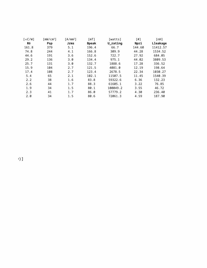
803.2 824 161.8 379 5.1 196.4 66.72105.9 1782 74.8 244 4.1 166.8 309.94285.4 2991 44.6 191 3.6 152.6 722.713970.3 4564 29.2 136 3.0 134.4 975.111241.7 5186 25.7 131 3.0 132.7 1888.623935.4 8381 15.9 104 2.7 121.5 4081.027251.0 7671 17.4 108 2.7 123.4 2678.5
162567.7 24770 5.4 65 2.1 102.1 11507.5686006.9 61961 2.2 38 1.6 83.8 59322.6381043.1 50555 2.6 44 1.7 88.3 61605.1778653.3 69835 1.9 34 1.5 80.1 100049.2558956.1 57785 2.3 41 1.7 86.0 57779.2813267.9 66856 2.0 34 1.5 80.6 72061.3
[mm2] [∞C/W] [mW/cm3] [A/mm2]Rq
lc = 4D + 2E + 2π{(A-E)/8 + (B-D)/4} = 4D + 2E + 0.25π[(A-E) +2(B-D)]
lw = 2π [(E-1mm)/2] + 2 {0.5(A-E) + 2mm} + 2(C+2mm) = π(E-1mm) + (A-E) +2C + 8mm
Without coil former:
1 mm
E
Coil former wall thickness
(A-E)2
C
1 mm
radius = (E-1mm)
1 mm1 mm
radius = 0.5(E-1mm)
2B
2D

[#] [nH] [watts]Npri Lleakage Power Loss
144.60 11412.57 0.4344.28 1534.52 0.9227.92 684.05 1.5544.02 3809.53 2.3617.28 336.52 2.6812.19 198.64 4.3422.34 1030.27 3.9711.45 1540.39 12.826.36 132.23 32.063.22 76.85 26.163.55 46.72 36.144.30 236.40 29.904.59 187.90 34.60

coil former coil former Ferroxcube Ferrooxcube
calculated calculated bobbin bobbin No bobbinlw Aw Lw Aw Lw
30.0 26.8 29 27.4 25.144.3 47.5 48.7 37.3 39.554.4 78.8 49.570.2 198.9 65.473.0 153.9 68.290.6 264.1 85.887.6 311.2 82.7
183.8 884.5 178.9207.3 3308.8 202.5235.3 1619.2 230.5235.3 3308.8 230.5266.0 2101.6 261.1266.0 3057.7 261.1

No bobbinAw43.569.1106.2241.3191.5312.9363.2985.5
3475.21737.63475.22245.43220.7