trailing arm 1947 1954 chevy pick-up - no limit …nolimit.net/tech/pdf/trailing-arm-new.pdf ·...
TRANSCRIPT
TRAILING ARM
1947 – 1954 CHEVY PICK-UP
Congrats on choosing the best riding and handling rear suspension for your Chevy. Trailing arm suspension can
be tricky to install correctly, so please follow our recommendations, and you will be smiling all the way to your
next Cruise-in.
*** Note. We spec the rear axle center line to be 36 ¾” from the rear tip of the frame. These trucks are old, and
they’ve taken a beating. We recommend that you set the bed box on the frame and position a tire under the
fender, close to the ride height and stance you want, and locate the desired axle centerline on your chassis. Just
do it. You’ll be happy later. ***
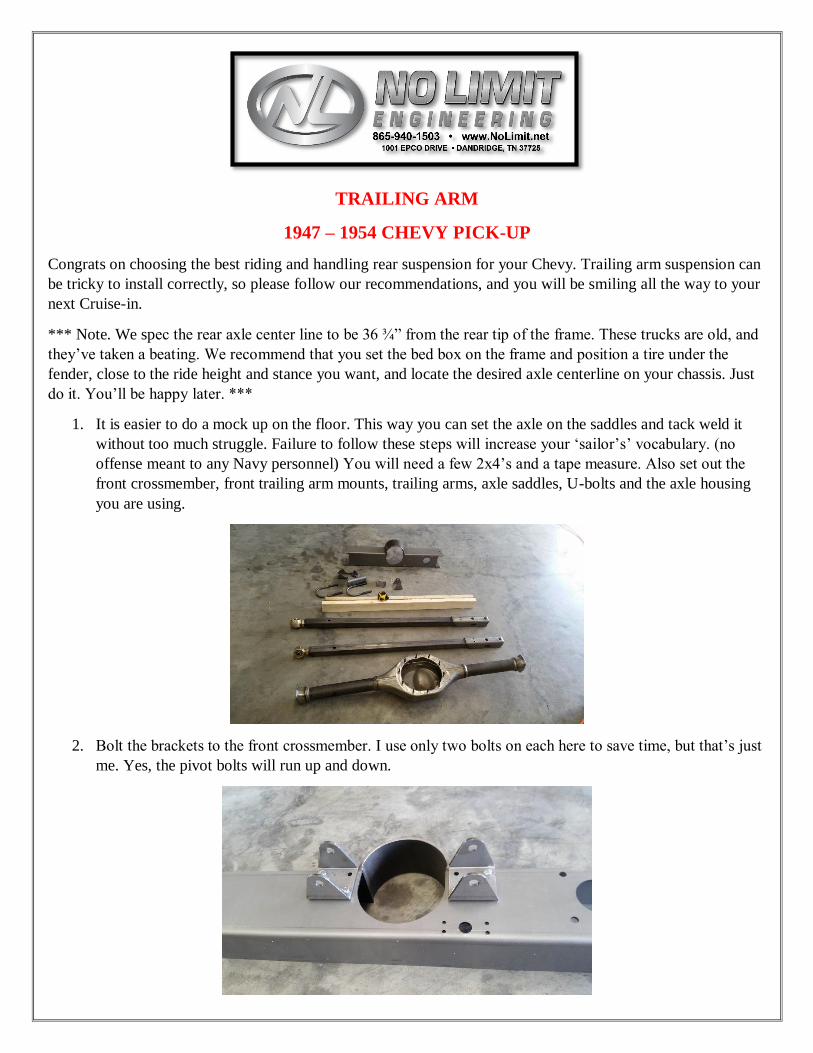
1. It is easier to do a mock up on the floor. This way you can set the axle on the saddles and tack weld it
without too much struggle. Failure to follow these steps will increase your ‘sailor’s’ vocabulary. (no
offense meant to any Navy personnel) You will need a few 2x4’s and a tape measure. Also set out the
front crossmember, front trailing arm mounts, trailing arms, axle saddles, U-bolts and the axle housing
you are using.
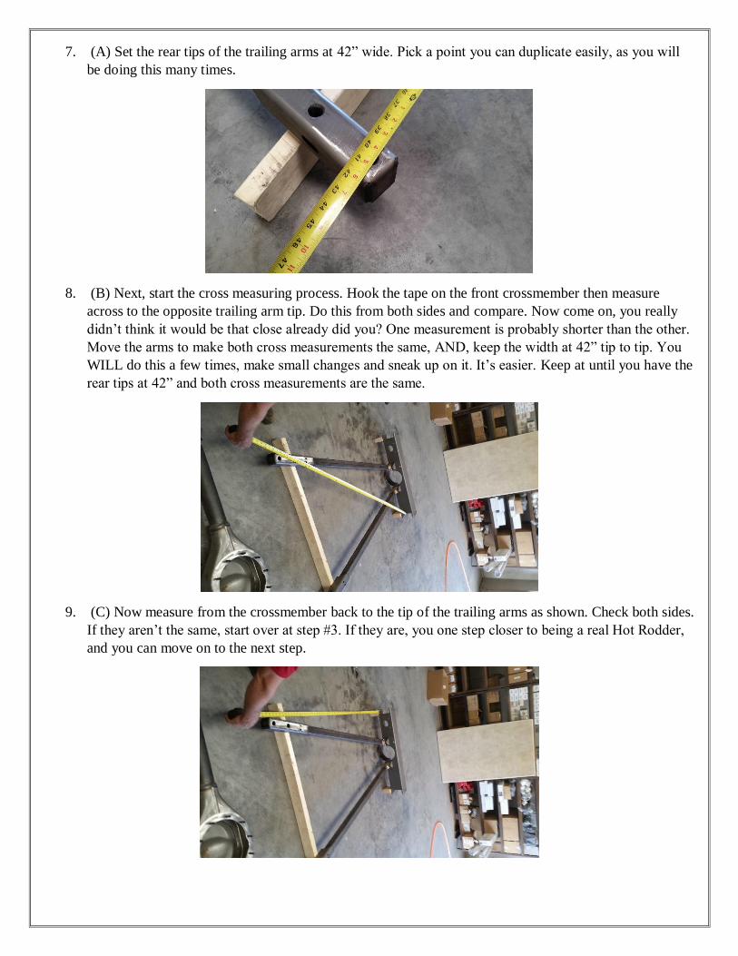
2. Bolt the brackets to the front crossmember. I use only two bolts on each here to save time, but that’s just
me. Yes, the pivot bolts will run up and down.

3. Adjust the pivot ball end of the trailing arm so that there is 1” of thread showing.
4. The pivot ball will fit into the front mount like this. Yes, the pivot bolt runs up and down. (I know,
everybody else does it the other – wrong – way. Trust us, we know what we’re doing. We’re the ones
that went to Engineering school). You will note a ¾” hole a few inches back from the pivot ball on the
top of the trailing arm. A really smart/cool guy might want to run the rear brake line inside the trailing
arm. Note the oval port just under the axle saddle area. – Just sayin.
5. OK, start your base set up. Set the front crossmember on 2x4’s, span the trailing arms out and set the
trailing arms on a 2x4 (or two separate pieces, it’s up to you) Take you time with the next few steps, or,
go find a sailor hat. Patients will be the key here.
6. There will be three basic measurements to check, over and over, and over, until it’s right on the money.
They will be:
A) Rear width, 42”
B) Cross measure, crossmember to rear tip
C) Front-to-back measure, crossmember to rear tip.
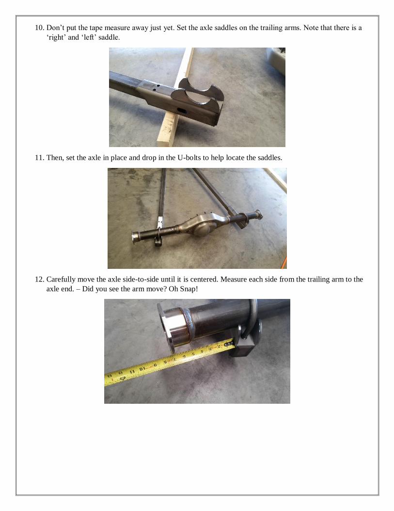
7. (A) Set the rear tips of the trailing arms at 42” wide. Pick a point you can duplicate easily, as you will
be doing this many times.
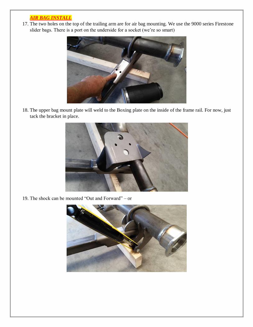
8. (B) Next, start the cross measuring process. Hook the tape on the front crossmember then measure
across to the opposite trailing arm tip. Do this from both sides and compare. Now come on, you really
didn’t think it would be that close already did you? One measurement is probably shorter than the other.
Move the arms to make both cross measurements the same, AND, keep the width at 42” tip to tip. You
WILL do this a few times, make small changes and sneak up on it. It’s easier. Keep at until you have the
rear tips at 42” and both cross measurements are the same.
9. (C) Now measure from the crossmember back to the tip of the trailing arms as shown. Check both sides.
If they aren’t the same, start over at step #3. If they are, you one step closer to being a real Hot Rodder,
and you can move on to the next step.
10. Don’t put the tape measure away just yet. Set the axle saddles on the trailing arms. Note that there is a
‘right’ and ‘left’ saddle.
11. Then, set the axle in place and drop in the U-bolts to help locate the saddles.
12. Carefully move the axle side-to-side until it is centered. Measure each side from the trailing arm to the
axle end. – Did you see the arm move? Oh Snap!

13. Now your set up should look like this and it’s time to cross measure again. This time hook the
crossmember and measure across to the end of the axle housing instead of the trailing arm tip. (No, there
is no picture of this. You’re a smart cookie, think about what you’re doing, you’ll figure it out).
14. Here’s the last check. Measure from the rear face of the crossmember back to the center of the axle
housing. It should be 55 ½”, or really, really close, like 55 ½”. If not, you guessed it, back to #3 Sailor
Jerry. But, if you nailed it, pass go and move to the next step.
15. Next is to set the pinion angle. With the set-up we walked you though here, the arms should be level.
You will need to rotate the housing to point the pinion UP 1 degree from level. Again, just trust us on
this one. Now that you moved the axle double check all the measurements from #7 to #14. Finally, tack
weld the axle saddles to the housing. You can remove the housing and weld the saddles on. *** Now, if
you don’t trust us on the pinion angle thing, just leave the saddles tacked in place until you drive the
truck and then you ca………. Just weld them on***
16. Remember way back in the beginning we asked you to check the axle center line? Well, here’s why. To
place the front crossmember in the chassis, you will need to calculate the position of the crossmember.
It’s an easy one. Just take the measurement from the rear tip of the frame to the axle center line that you
want ______ + 55 ½” = ________ this is the measurement from the rear tip of the frame to the back face
of the trailing arm crossmember. The crossmember will fit inside the OE frame rails. I clamp a straight
edge (like the long 2x4) to the back of the frame rails so that I can measure straight forward. This
crossmember can be bolted or welded in place. Now you can re-assemble the trailing arms and rear axle
into place. Snug the U-bolts and use jack stands to hold the axle housing up at ride height.
AIR BAG INSTALL
17. The two holes on the top of the trailing arm are for air bag mounting. We use the 9000 series Firestone
slider bags. There is a port on the underside for a socket (we’re so smart)
18. The upper bag mount plate will weld to the Boxing plate on the inside of the frame rail. For now, just
tack the bracket in place.
19. The shock can be mounted “Out and Forward” – or

20. It can be mounted “In and Back” (I prefer “Out and Forward” as it has less interference with the panhard
rod) the top shock mount is a simple tube welded to the top of the frame. The shocks can be tilted
forward or back up to 30 degrees, which will allow for more axle travel.
COIL OVER SHOCK INSTALL
21. The lower mount will be on the back side of the housing, just inside of the trailing arm. Set the face
level up and down. Tack weld only.
22. The upper mount is a crossmember that spans from boxing plate to boxing plate. Shown here resting on
the top of the housing. We recommend that you place the crossmember “Behind” the shocks, to give the
axle housing more room. To help position the crossmember, bolt the shocks in place to the lower mounts
–with no springs, drop the axle 2” to 2 ½” from ride height, then bolt the tops of the shocks to the
crossmember. Fit and tack the crossmember in place.

PANHARD ROD INSTALATION
23. You will need to fit the axle mount to the housing. It will probably be partially over the center section.
Assemble the panhard rod with ½” of thread showing on the adjuster to get an idea of how it will fit.
24. Looking down, the panhard rod may tip “back” to clear the coil-over shocks. That’s OK. Looking at the
bar from the back, try to keep it level at Ride Height. You may need to fabricate a small spacer for the
chassis side mount to do this, depending on the chosen ride height.
For all installations, air or coil-over, use a floor jack to move the suspension up and down the full stroke
of the shocks and/or bags. Make sure that nothing is interfering or needs to be adjusted. This is your
chance to move shock and bag mounts around to get what you want. Take the time to do this, that’s what
a real Hot Rodder would do. When your happy, pull it apart, fully weld everything, paint or powdercoat
(or not, up to you) and put it back together. Put a feather in your cap and a sticker on your tool box, you
did it, and your ride is one step closer.