traffic allocation
DESCRIPTION
opisTRANSCRIPT

NORTEL NETWORKS CONFIDENTIAL Traffic Allocation, September 2000
CDMA Traffic AllocationCDMA Traffic Allocation
CDMA RF EngineeringCDMA RF Engineering
CDMA Network EngineeringCDMA Network Engineering
Nortel Wireless SolutionsNortel Wireless Solutions

Traffic Allocation, September 2000NORTEL NETWORKS CONFIDENTIAL
Methods of Traffic Allocation
• Idle Mode
— Mobile HASHING using Channel List
— Global Service Re-Direction (GSR) using Access OverLoad Class ACCOLC(0 - 9, A - F)
• Active Mode (Call Setup)
— Multi Carrier Traffic Allocation (MCTA)

Traffic Allocation, September 2000NORTEL NETWORKS CONFIDENTIAL
Idle Mode AllocationGSR/Channel List
• Mobile is allocated to one of the available channels (with active
Paging Channel) while in Idle Mode.
• Allocation of mobiles to the available frequencies is solely
dependent on Allocation algorithm.
• Mobile Remains on that channel while in the channel’s coverage
area (Excluding step down area).
• The two methods of allocation, GSR and HASHING (Channel List),
are Mutually exclusive to prevent ping-Pong
• Margin required between Allocation and step down sectors/BTSs

Traffic Allocation, September 2000NORTEL NETWORKS CONFIDENTIAL
Channel List (HASHING)
• Mobile is turned on or Enters the region where more than one Paging Channel is configured.
• A Channel List message with available channels is continuously broadcasted on the Paging Channel.
• Mobile Chooses the desired channel by means of its IS-95 HASHING Function (While in Idle Mode).
• Mobile remains on that channel until it leaves the area where the additional channels are available or gets directed to the underlying channel (Step Down).
• Design Considerations— Hashing will provide a statistical even traffic distribution between carriers.
— Hashing can be used between multiple carriers (F1, F2, F3, ….etc).
— GSR is used on the border sectors to provide step down direction to underlying Frequency (for all mobiles).
— A margin is required between Channel List BTS’s and GSR Step Down Sectors to prevent Ping-Pong
— Step Down should not occur in high traffic area.

Traffic Allocation, September 2000NORTEL NETWORKS CONFIDENTIAL
Channel List at Carrier Boundaries
Margin to prevent Ping-Pong (NO HASHING)
GSR Hand Down on Outward Facing Sectors
Channel List/ Hashing Idle Mode Allocation
F2F1
F2F1F
1
F2F1
Margin
Active Call on F2 until RTD
Idle Mode Allocation

Traffic Allocation, September 2000NORTEL NETWORKS CONFIDENTIAL
Global Service Re-Direction (GSR)• Mobile is turned on or Enters the region where GSR for Idle Mode Traffic
Allocation is active
• GSR directs mobiles based on the Access Overload Class set within the GSR Message (a bit mapping Word (16 bits 0 - F))
• GSR Message can be broadcasted full or part time on the Paging Channel
• GSR Messages should be exclusive between different Channels
• Mobile remains on that channel until it leaves the area where the additional channels are available or gets directed to the underlying channel.
— Border sectors provides a GSR message sending all mobiles to the underlay frequency
• Design Considerations— GSR can provide a selectable (10% increment) allocation of mobiles.
— Step down GSR should not overlap with Hashing or Traffic Allocation GSR
— A margin is needed between GSR Traffic Allocation Sectors and GSR Hand Down Sectors to prevent Ping-Pong
— GSR is Sector Settable which can reduce the required Margin
— Hand Down should not occur in high traffic area
Traffic Allocation, September 2000NORTEL NETWORKS CONFIDENTIAL
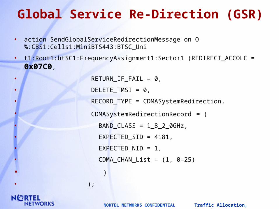
Global Service Re-Direction (GSR)
• action SendGlobalServiceRedirectionMessage on O%:CBS1:Cells1:MiniBTS443:BTSC_Uni
• t1:Root1:btSC1:FrequencyAssignment1:Sector1 (REDIRECT_ACCOLC = 0x07C0,
• RETURN_IF_FAIL = 0,
• DELETE_TMSI = 0,
• RECORD_TYPE = CDMASystemRedirection,
• CDMASystemRedirectionRecord = (
• BAND_CLASS = 1_8_2_0GHz,
• EXPECTED_SID = 4181,
• EXPECTED_NID = 1,
• CDMA_CHAN_List = (1, 0=25)
• )
• );
Traffic Allocation, September 2000NORTEL NETWORKS CONFIDENTIAL
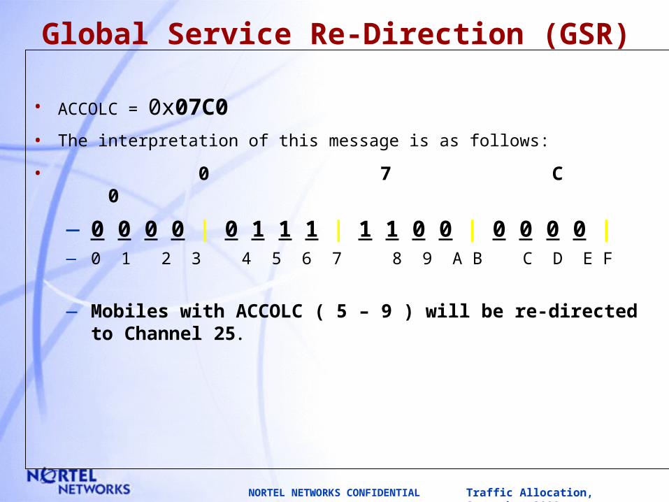
Global Service Re-Direction (GSR)
• ACCOLC = 0x07C0
• The interpretation of this message is as follows:
• 0 7 C 0
—0 0 0 0 | 0 1 1 1 | 1 1 0 0 | 0 0 0 0 | — 0 1 2 3 4 5 6 7 8 9 A B C D E F
— Mobiles with ACCOLC ( 5 – 9 ) will be re-directed to Channel 25.

Traffic Allocation, September 2000NORTEL NETWORKS CONFIDENTIAL
Global Service Re-Direction (GSR)
• action SendGlobalServiceRedirectionMessage on O%:CBS1:Cells1:MiniBTS143:BTSC_Uni
• t1:Root1:btSC1:FrequencyAssignment1:Sector1 (REDIRECT_ACCOLC = 0xF800,
• RETURN_IF_FAIL = 0,
• DELETE_TMSI = 0,
• RECORD_TYPE = CDMASystemRedirection,
• CDMASystemRedirectionRecord = (
• BAND_CLASS = 1_8_2_0GHz,
• EXPECTED_SID = 4181,
• EXPECTED_NID = 1,
• CDMA_CHAN_List = (1, 0=200)
• )
• );

Traffic Allocation, September 2000NORTEL NETWORKS CONFIDENTIAL
Global Service Re-Direction (GSR)
• ACCOLC = 0xF800
• The interpretation of this message is as follows:
• F 8 0 0
—1 1 1 1 | 1 0 0 0 | 0 0 0 0 | 0 0 0 0 | — 0 1 2 3 4 5 6 7 8 9 A B C D E F
— Mobiles with ACCOLC ( 0 - 4 ) will be re-directed to Channel 200.

Traffic Allocation, September 2000NORTEL NETWORKS CONFIDENTIAL
GSR at Carrier Boundaries
Margin to prevent Ping-Pong NO GSR on Outward Facing Sectors
GSR Hand Down on Outward Facing Sectors
GSR Idle Mode Allocation
F2F1
F2F1F
1
F2F1
Margin
Active Call on F2 until RTD
Idle Mode Allocation

Traffic Allocation, September 2000NORTEL NETWORKS CONFIDENTIAL
Requirements to Set Channel Listor GSR
Channel ListChannel List
• Set the channels in the “ChannelList” parameter (configurable) under the BTSC MO of every BTS that the channel list is to be enabled.
• The order of the channels must be the same across the board.
• Legacy BTS has to be re-loaded.
• Settable parameter with the Metro Per DCG.
• Each DCG can have ONLY ONE Channel List (all Carriers on the same DCG will have the same Channel List).
GSRGSR
• Send the “SendGlobalServiceRedirection” action at the specific Sector MO to turn on GSR on the specific sector. The “REDIRECT_ACCOLC” parameter controls the allocation of the mobiles.
• Settable parameter (Action ON / OFF).
Traffic Allocation, September 2000NORTEL NETWORKS CONFIDENTIAL
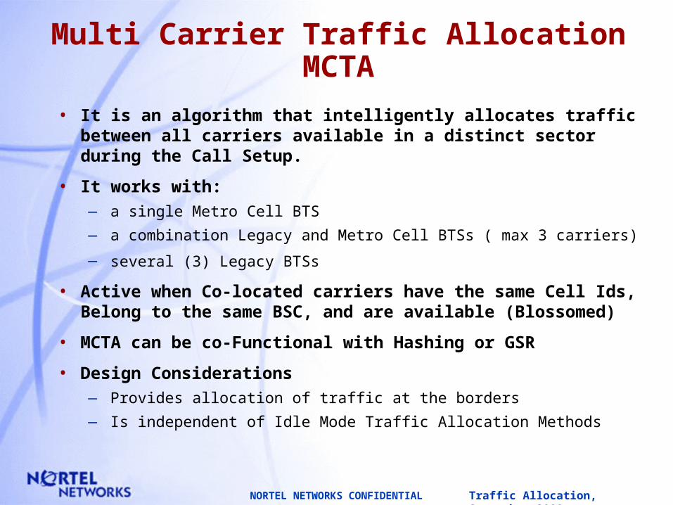
Multi Carrier Traffic AllocationMCTA
• It is an algorithm that intelligently allocates traffic between all carriers available in a distinct sector during the Call Setup.
• It works with:— a single Metro Cell BTS
— a combination Legacy and Metro Cell BTSs ( max 3 carriers)
— several (3) Legacy BTSs
• Active when Co-located carriers have the same Cell Ids, Belong to the same BSC, and are available (Blossomed)
• MCTA can be co-Functional with Hashing or GSR
• Design Considerations— Provides allocation of traffic at the borders
— Is independent of Idle Mode Traffic Allocation Methods
Traffic Allocation, September 2000NORTEL NETWORKS CONFIDENTIAL
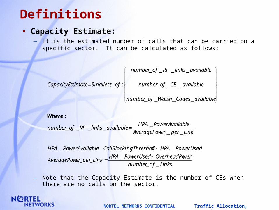
Definitions• Capacity Estimate:
— It is the estimated number of calls that can be carried on a specific sector. It can be calculated as follows:
— Note that the Capacity Estimate is the number of CEs when there are no calls on the sector.
Linksofnumber
werOverheadPoPowerUsedHPAker_per_LinAveragePow
PowerUsedHPAdngThresholCallBlockiablePowerAvailHPA
LinkpererAveragePow
ablePowerAvailHPAavailablelinksRFofnumber
availableCodesWalshofnumber
availableCEofnumber
availablelinksRFofnumber
ofSmallesttimateCapacityEs
__
_
__
__
_____
____
___
____
:_
:Where
Traffic Allocation, September 2000NORTEL NETWORKS CONFIDENTIAL
Definitions (cont.)
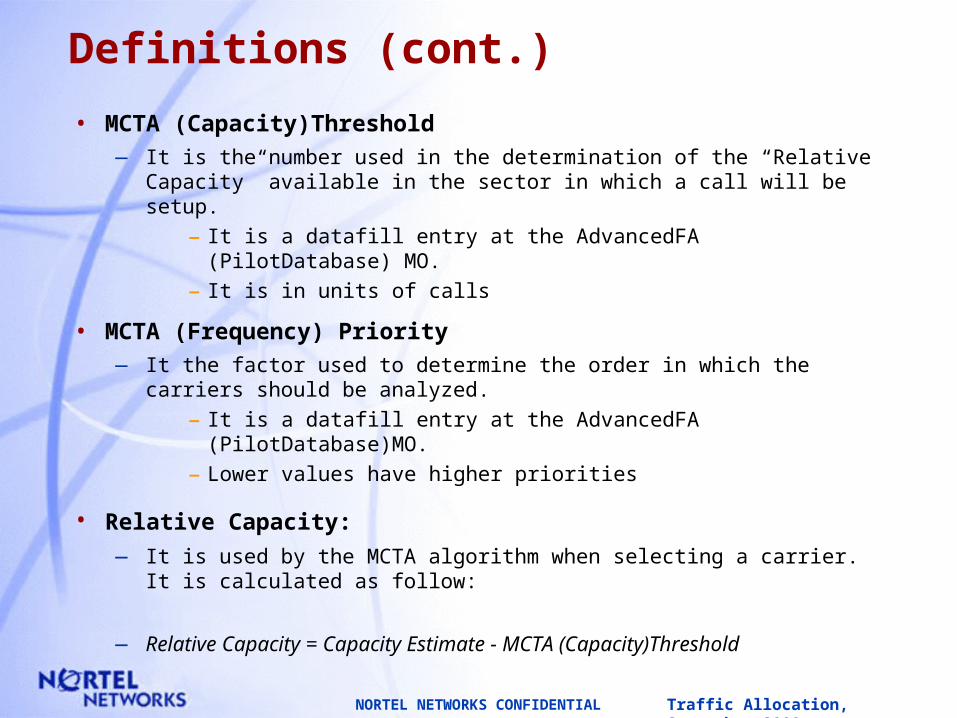
• MCTA (Capacity)Threshold— It is the number used in the determination of the “Relative Capacity”
available in the sector in which a call will be setup.
– It is a datafill entry at the AdvancedFA (PilotDatabase) MO.
– It is in units of calls
• MCTA (Frequency) Priority— It the factor used to determine the order in which the carriers should
be analyzed.
– It is a datafill entry at the AdvancedFA (PilotDatabase)MO.
– Lower values have higher priorities
• Relative Capacity:
— It is used by the MCTA algorithm when selecting a carrier. It is calculated as follow:
— Relative Capacity = Capacity Estimate - MCTA (Capacity)Threshold
Traffic Allocation, September 2000NORTEL NETWORKS CONFIDENTIAL
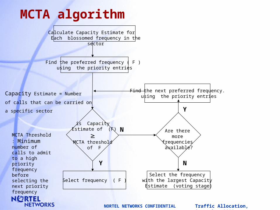
MCTA algorithm
Find the preferred frequency ( F ) using the priority entries
Calculate Capacity Estimate for Each blossomed frequency in the sector
is Capacity Estimate of (F)
MCTA threshold
of F
Select frequency ( F )
Find the next preferred frequency. using the priority entries
Are there morefrequencies available?
Select the frequency with the largest Capacity Estimate (voting stage)
Y
N
Y
N
Capacity Estimate = Number
of calls that can be carried on
a specific sector
MCTA Threshold : Minimum number of calls to admit to a high priority frequency before selecting the next priority frequency

Traffic Allocation, September 2000NORTEL NETWORKS CONFIDENTIAL
Frequency F1 F2 F3
Frequency Priority (datafill) 0 0 0
Capacity Threshold (datafill) 64 64 64
Calculated Capacity Estimate 10 12 8
is Estimate > Threshold No No No
Calculate Relative Capacity -54 -52 -56
Select highest Capacity Estimate
MCTA algorithm
Example 1: Even Traffic Distribution
Traffic Allocation, September 2000NORTEL NETWORKS CONFIDENTIAL
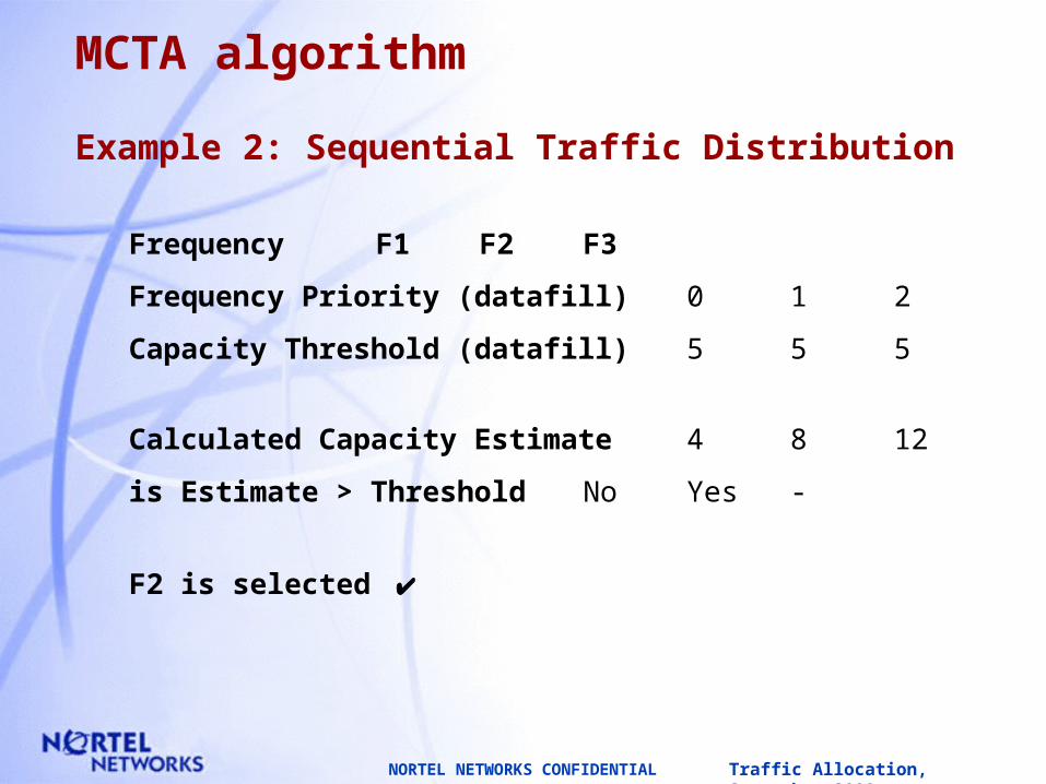
Frequency F1 F2 F3
Frequency Priority (datafill) 0 1 2
Capacity Threshold (datafill) 5 5 5
Calculated Capacity Estimate 4 8 12
is Estimate > Threshold No Yes -
F2 is selected
MCTA algorithm
Example 2: Sequential Traffic Distribution

Traffic Allocation, September 2000NORTEL NETWORKS CONFIDENTIAL
Frequency F1 F2 F3
Frequency Priority (datafill) 0 1 2
Capacity Threshold (datafill) 5 5 64
Calculated Capacity Estimate 2 4 6
is Estimate > Threshold No No No
Calculate Relative Capacity -3 -1 -58
Select highest Capacity Estimate
MCTA algorithm
Example 3: Sequential Traffic Distribution
Traffic Allocation, September 2000NORTEL NETWORKS CONFIDENTIAL
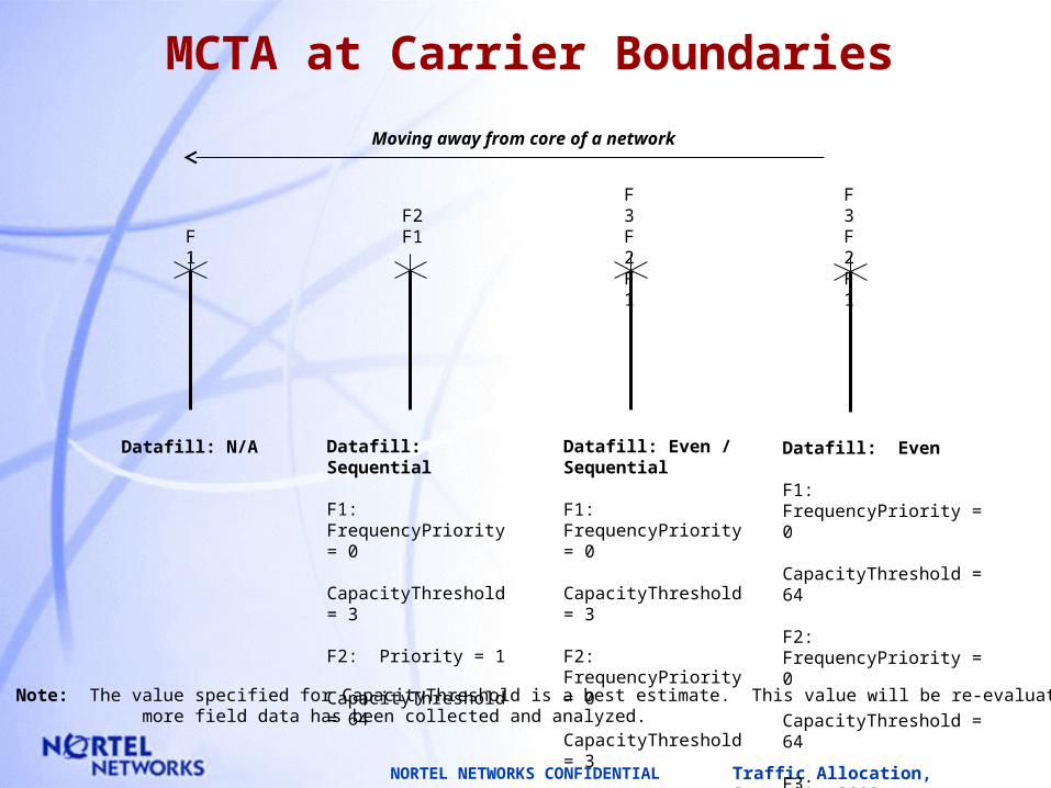
MCTA at Carrier Boundaries
F3F2F1
F2F1F
1
Datafill: Even / Sequential
F1: FrequencyPriority = 0 CapacityThreshold = 3
F2: FrequencyPriority = 0 CapacityThreshold = 3
F3: FrequencyPriority = 1 CapacityThreshold = 64
Datafill: Sequential
F1: FrequencyPriority = 0 CapacityThreshold = 3
F2: Priority = 1 CapacityThreshold = 64
Datafill: N/A Datafill: Even
F1: FrequencyPriority = 0 CapacityThreshold = 64
F2: FrequencyPriority = 0 CapacityThreshold = 64
F3: FrequencyPriority = 0 CapacityThreshold = 64
F3F2F1
Moving away from core of a network
Note: The value specified for CapacityThreshold is a best estimate. This value will be re-evaluated once more field data has been collected and analyzed.

Traffic Allocation, September 2000NORTEL NETWORKS CONFIDENTIAL
Multi Carrier Traffic AllocationMCTA
MCTA Algorithm
At call set-up, the system sends a ‘capacity request’ message to each BTS/DCG configured as a part of the MCTA cell site and Blossomed.
Each BTS/DCG responds with its Capacity Estimate in the ‘capacity response’ message.
The system then uses the Carrier Determination Algorithm (CDA) to select the best carrier.

Traffic Allocation, September 2000NORTEL NETWORKS CONFIDENTIAL
Multi Carrier Traffic AllocationMCTA
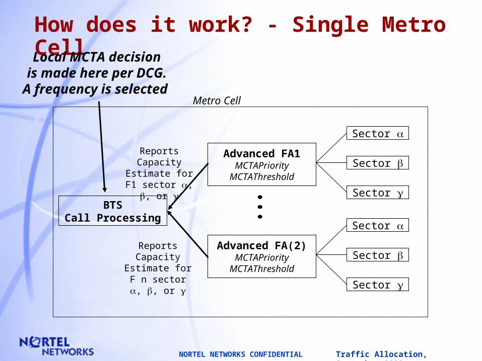
Where does the MCTA decision take place?
All Metrocell system - the MCTA decision takes place at the metrocell itself on a DCG basis.
For multiple DCGs in 1 cellsite, the MCTA decision takes place at the SBS level.
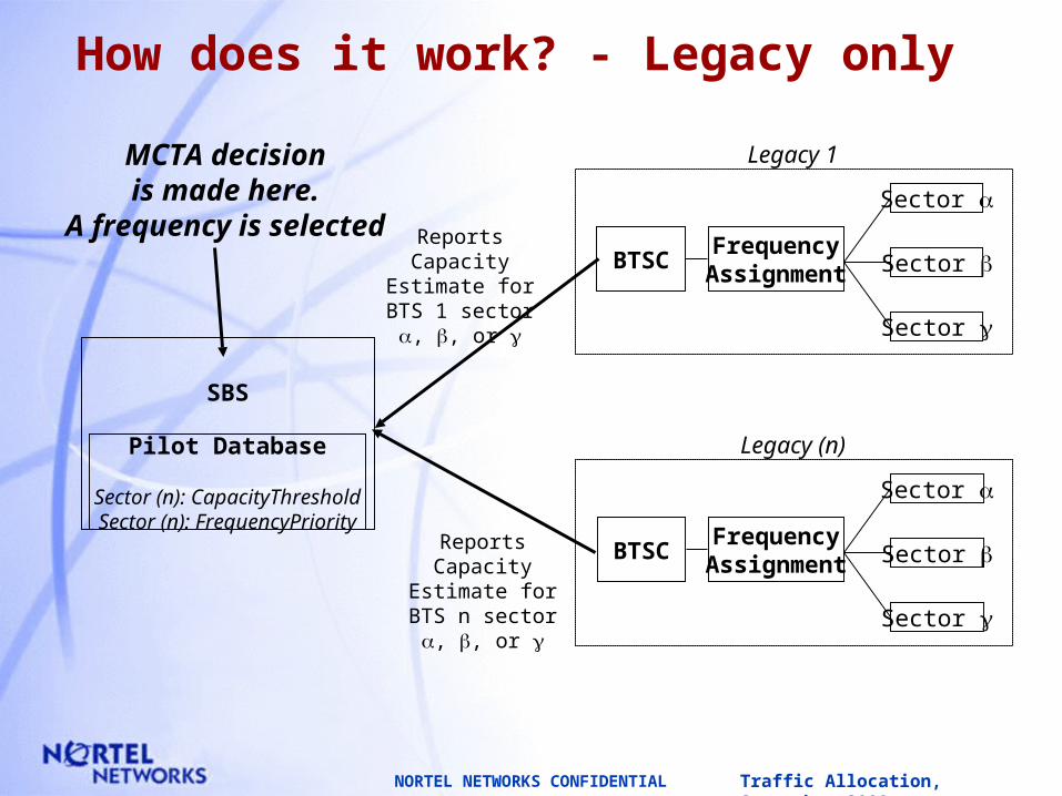
All Legacy system the MCTA decision takes place at the SBS level.
A Metrocell - Legacy System - part of the decision takes place at the metrocell/DCG and the final decision at the SBS level.
Traffic Allocation, September 2000NORTEL NETWORKS CONFIDENTIAL
How does it work? - Single Metro CellLocal MCTA decisionis made here per DCG.A frequency is selected
Metro Cell
BTSCall Processing
Advanced FA1MCTAPriority
MCTAThreshold
Sector
Sector
Sector
Sector
Sector
Sector
Advanced FA(2)MCTAPriority
MCTAThreshold
Reports Capacity Estimate for F1 sector , , or
Reports Capacity Estimate for F n sector , , or
Traffic Allocation, September 2000NORTEL NETWORKS CONFIDENTIAL
How does it work? - Legacy only
MCTA decisionis made here.
A frequency is selected
SBS
Pilot Database
Sector (n): CapacityThresholdSector (n): FrequencyPriority
Reports Capacity Estimate for BTS 1
sector , , or
Reports Capacity Estimate for BTS n
sector , , or
FrequencyAssignment
Sector
Sector
Sector
Legacy (n)
BTSC
FrequencyAssignment
Sector
Sector
Sector
Legacy 1
BTSC

Traffic Allocation, September 2000NORTEL NETWORKS CONFIDENTIAL
How does it work? - Metro Cell & Legacy
Final MCTA decisionis made here.
A Frequency is selected
SBS
Pilot Database
Sector (n): CapacityThresholdSector (n): FrequencyPriority
Metro Cell 1
Reports Capacity Estimate for Legacy
sector , , or
Reports Capacity Estimate for selected
Frequency sector , , or
BTSCall Processing
Advanced FA1MCTAPriority
MCTAThreshold
Sector
Sector
Sector
Sector
Sector
Sector
Advanced FA(2)MCTAPriority
MCTAThreshold
Reports Capacity Estimate for F1 sector , , or
Reports Capacity Estimate for F n sector , , or
Initial MCTA decisionis made here, one frequency
is selected for each Metro Cell
FrequencyAssignment
Sector
Sector
Sector
Legacy 1
BTSC
Traffic Allocation, September 2000NORTEL NETWORKS CONFIDENTIAL
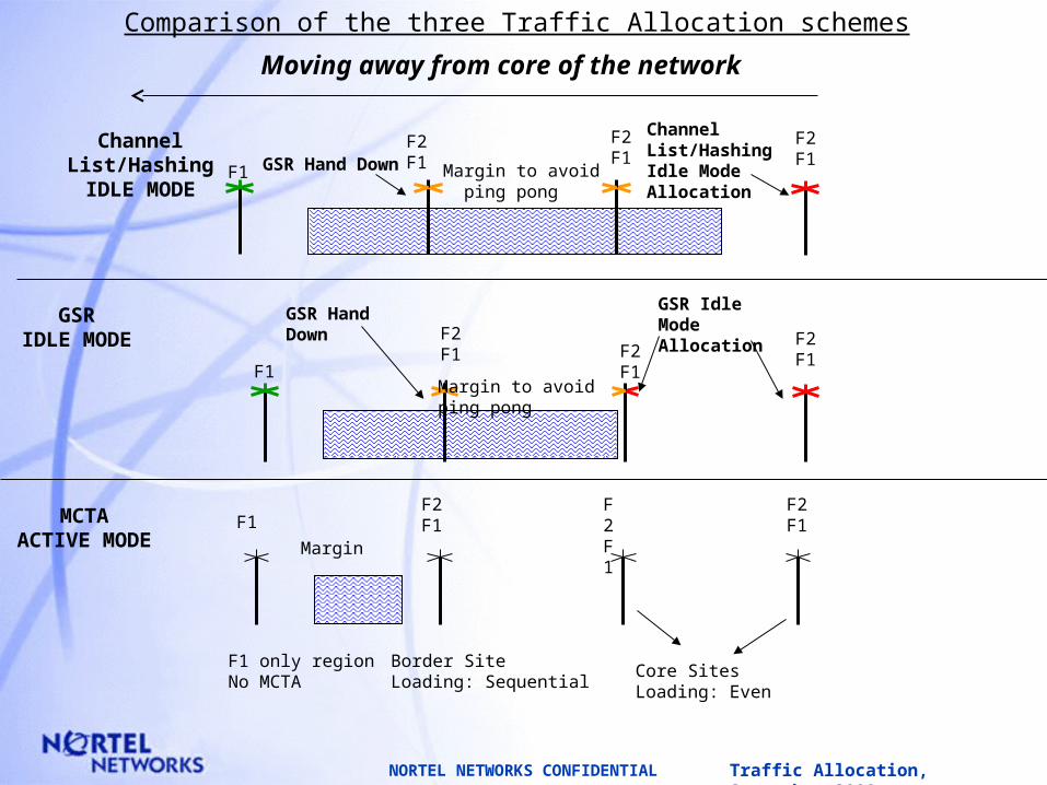
Comparison of the three Traffic Allocation schemes
F2F1GSR Hand Down
Channel List/Hashing Idle Mode Allocation
F2F1
F2F1F1 Margin to avoid
ping pong
GSR Hand Down
GSR Idle Mode Allocation
F2F1
F2F1
F1
F2F1
Margin to avoid ping pong
F2F1
F2F1F1
Moving away from core of the network
F1 only regionNo MCTA
Border SiteLoading: Sequential
Core SitesLoading: Even
F2F1
Channel List/HashingIDLE MODE
GSRIDLE MODE
MCTAACTIVE MODE Margin

Traffic Allocation, September 2000NORTEL NETWORKS CONFIDENTIAL
Requirements to Set MCTA
• Use the same Cell Id for all carriers, for at most 3 carriers, within the same MCTA site.
• All Co-located MCTA BTS’s must belong to the same BSC.
• Set the “MCTATimeout” parameter to a value that allows enough time for the “Capacity Response” message from all BTSs to be received at the SBS. Recommended value is 100 ms.
• Set both the “CapacityThreshold” and the “FrequencyPriority” PDB parameters of each sector to a proper value dependant on the MCTA RF design.
• Set “frqvct” field (cdma_frequency_vector field) of each CDMAPART table entry of an MCTA sector to have the appropriate frequency. Once done, the MCTA OMs will be collected on per frequency basis.
Traffic Allocation, September 2000NORTEL NETWORKS CONFIDENTIAL
MCTA and Step-DownHHO Interaction
• If MCTA is turned on at the step-down sites, then special considerations need to be made to have a successful step-down:
— MPHHO must be turned on.
— The first target BTS in the target list must be a non-MCTA BTS. The rest of the targets can be either MCTA or non-MCTA BTSs.
• If the above is not feasible, then, to have a successful step-down, MCTA must be disabled at the step-down site (i.e. use different Cell Id at the step-down site).