trade of motor mechanic - solas elearning · module 6 - unit 1 clutch system trade of motor...
TRANSCRIPT
Trade of Motor Mechanic
Module 6
Unit 1
ClutCh SyStem
Phase
2
Produced by
In cooperation with:
Subject Matter Experts
Martin McMahon
&
CDX Global
Curriculum Revision 2.2 16-01-07
© SOLAS 2013

Revision 3.0 November 2013
Module 6 - Unit 1 Clutch System
Trade of Motor Mechanic - Phase 2 Course Notes
Table of ContentsIntroduction ........................................................................................................ 1Unit Objective ..................................................................................................... 21.0 Safety and Precautionary Procedures ...................................................... 3
1.1 Health and Safety .......................................................................... 32.0 Personal Hazards and Environmental Issues ......................................... 4
2.1 Personal Hazards .......................................................................... 42.2 Environmental Issues ................................................................... 4
3.0 The Clutch in the Transmission System ................................................. 53.1 Clutch Principles ........................................................................... 5
4.0 The Single-Plate Clutch System .............................................................. 64.1 Single-Plate Clutches .................................................................... 64.2 Pressure Plate ................................................................................ 74.3 Driven/Centre Plate ...................................................................... 84.4 Clutch Release Bearing(Throw-out Bearing) ............................... 9
5.0 Friction Principles of the Clutch System ...............................................105.1 Friction .........................................................................................10
6.0 The Dual Mass Flywheel ........................................................................136.1 Dual Mass Flywheels ...................................................................13
7.0 Cable/Hydraulic Clutch Release Operating Mechanisms ....................157.1 Operating Mechanisms ...............................................................157.2 Associated Science and Maths .....................................................167.3 Moments ......................................................................................187.4 Hydraulic Pressure & Force ........................................................197.5 Force Ratio (Hydraulics) ............................................................ 20
8.0 Clutch Pedal Leverage Ratio ..................................................................219.0 RemovingandRefittingaClutchCable .................................................2110.0 Effects of Incorrect Clutch Adjustment .................................................2111.0 Factors Affecting Torque Transmission ................................................ 22
11.1 Factors Affecting Torque Transmission ..................................... 2212.0 Maximum Torque Transmitted by a Single Plate Clutch...................... 23
12.1 Torque Transmitted by a Clutch ..................................................... 2312.2 Factors Affecting Torque Transmission Calculation .................. 24
13.0 Common Clutch Faults .......................................................................... 2513.1 Causes of Common Faults ......................................................... 25
14.0 Servicing Clutch System Components .................................................. 2615.0 Bleeding a Hydraulic Clutch System ..................................................... 26Self Assessment ................................................................................................ 27Suggested Exercises ......................................................................................... 29Training Resources ........................................................................................... 29Suggested Further Reading .............................................................................. 30

Revision 3.0 November 20131
Module 6 - Unit 1 Clutch System
Trade of Motor Mechanic - Phase 2 Course Notes
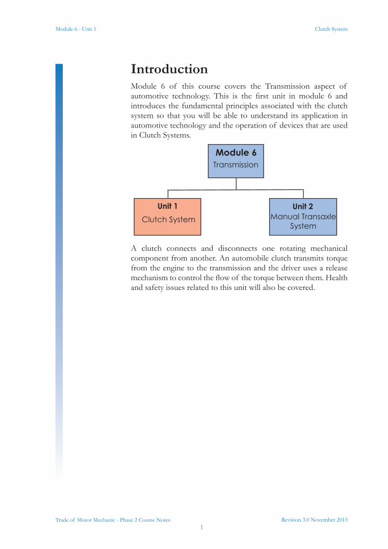
IntroductionModule 6 of this course covers the Transmission aspect of automotive technology. This is the first unit in module 6 and introduces the fundamental principles associated with the clutch system so that you will be able to understand its application in automotive technology and the operation of devices that are used in Clutch Systems.
A clutch connects and disconnects one rotating mechanical component from another. An automobile clutch transmits torque from the engine to the transmission and the driver uses a release mechanism to control the flow of the torque between them. Health and safety issues related to this unit will also be covered.
Module 6Transmission
Unit 1 Unit 2Clutch System Manual Transaxle
System

Module 6 - Unit 1
Revision 3.0 November 20132
Clutch System
Trade of Motor Mechanic - Phase 2 Course Notes
Unit ObjectiveBy the end of this unit each apprentice will be able to:
• State and apply the safety and precautionary procedures applicable to working on the clutch system
• Describe the personal hazards and environmental issues associated with clutch lining dust and clutch fluid
• State the purpose of the clutch within the transmission system
• Describe the structure and principles of operation of the single-plate dry friction diaphragm spring clutch system
• Outline the friction principles applicable to the clutch system
• State the purpose of the dual mass flywheel and outline the fundamental principles of operation
• Describe the principles of operation of the cable and hydraulic clutch release mechanisms
• Calculate the clutch pedal leverage ratio
• Remove and refit a clutch cable
• State the effects of incorrect clutch adjustment
• State the factors affecting torque transmission
• Calculate the maximum torque possible to be transmitted by a single plate clutch
• List the common clutch faults and their related symptoms and causes
• Remove, examine and refit/replace clutch system components
• Bleed a hydraulic clutch system
Revision 3.0 November 20133
Module 6 - Unit 1 Clutch System
Trade of Motor Mechanic - Phase 2 Course Notes
1.0 Safety and Precautionary Procedures
1.1 Health and SafetyIf the proper safety procedures are not adhered to when working on Clutch Systems this could lead to serious injury/health problems e.g. Respiratory problems to personnel.
Instruction is given in the proper safety procedures applicable to working on clutch systems which include safe use of:
• Vehicle lifts
• Engine support beams
• Gearbox jacks
• Use of suitable eye protection
• Latex gloves
• Safety foot wear
• Safe removal of clutch dust
• Use of suitable face mask to avoid respiratory problems
• Working with appropriate clutch tools
• Prevention of clutch fluid spillage
• Assistance for gearbox removal and refitting using industry recommended manual handling methods
Refer to motor risk assessments, Environmental policy and Material Safety Data Sheets (MSDS)
Key Learning Points• Safety and precautionary procedures applicable to working
on the clutch system, including safe use of vehicle lifts, engine support beam and gearbox jacks, use of eye protection and latex gloves, safe removal of clutch dust, use of suitable face mask to avoid respiratory problems, working with appropriate clutch tools, prevention of clutch fluid spillage, assistance for gearbox removal and refitting using industry-recommended manual handling methods
Module 6 - Unit 1
Revision 3.0 November 20134
Clutch System
Trade of Motor Mechanic - Phase 2 Course Notes
2.0 Personal Hazards and Environmental Issues
2.1 Personal HazardsIf the proper safety procedures are not adhered to in regard to linings dust and brake/clutch fluid when working on the Clutch/Breaking Systems this could lead to serious health problems e.g.
• Respiratory problems from airborne dust
• Asbestos dust causes lung cancer (may not show for decades after exposure)
• Eye damage from fluid splashes
Instruction is given in the proper safety procedures applicable to working on Clutch/braking systems which include the following key points:
• Use of appropriate PPE
Refer to motor risk assessments, Environmental policy and Material Safety Data Sheets (MSDS)
2.2 Environmental IssuesThe Storage and disposal of brake clutch lining dust and clutch fluid must comply with current laws and regulations.
Key Learning Points• Personal hazards associated with clutch lining dust and
clutch fluid
Revision 3.0 November 20135
Module 6 - Unit 1 Clutch System
Trade of Motor Mechanic - Phase 2 Course Notes
3.0 The Clutch in the Transmission System
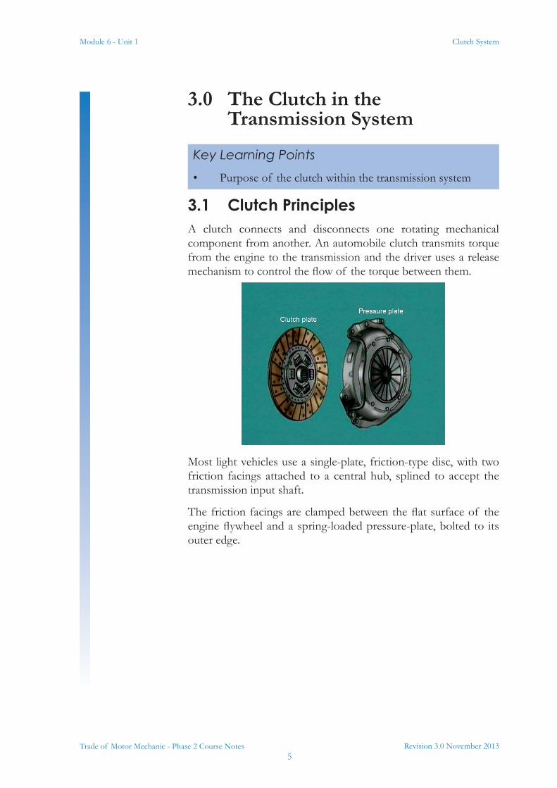
3.1 Clutch PrinciplesA clutch connects and disconnects one rotating mechanical component from another. An automobile clutch transmits torque from the engine to the transmission and the driver uses a release mechanism to control the flow of the torque between them.
Most light vehicles use a single-plate, friction-type disc, with two friction facings attached to a central hub, splined to accept the transmission input shaft.
The friction facings are clamped between the flat surface of the engine flywheel and a spring-loaded pressure-plate, bolted to its outer edge.
Key Learning Points• Purpose of the clutch within the transmission system
Module 6 - Unit 1
Revision 3.0 November 20136
Clutch System
Trade of Motor Mechanic - Phase 2 Course Notes
4.0 The Single-Plate Clutch System
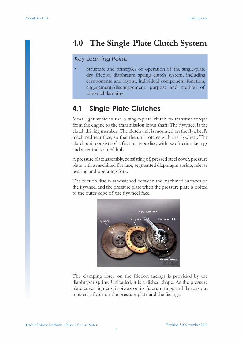
4.1 Single-Plate ClutchesMost light vehicles use a single-plate clutch to transmit torque from the engine to the transmission input shaft. The flywheel is the clutch driving member. The clutch unit is mounted on the flywheel’s machined rear face, so that the unit rotates with the flywheel. The clutch unit consists of a friction-type disc, with two friction facings and a central splined hub.
A pressure plate assembly, consisting of, pressed steel cover, pressure plate with a machined flat face, segmented diaphragm spring, release bearing and operating fork.
The friction disc is sandwiched between the machined surfaces of the flywheel and the pressure plate when the pressure plate is bolted to the outer edge of the flywheel face.
The clamping force on the friction facings is provided by the diaphragm spring. Unloaded, it is a dished shape. As the pressure plate cover tightens, it pivots on its fulcrum rings and flattens out to exert a force on the pressure plate and the facings.
Key Learning Points• Structure and principles of operation of the single-plate
dry friction diaphragm spring clutch system, including components and layout, individual component function, engagement/disengagement, purpose and method of torsional damping
Revision 3.0 November 20137
Module 6 - Unit 1 Clutch System
Trade of Motor Mechanic - Phase 2 Course Notes
The transmission input shaft passes through the centre of the pressure plate. Its parallel splines engage with the internal splines of the central hub, on the friction disc.
With engine rotation, torque can now be transmitted from the flywheel through the friction disc, to the central hub and to the transmission. A group of torsional springs located between the clutch hub and lining dampens driveline shocks and vibration.
When the clutch pedal is depressed, the movement is transferred through the operating mechanism, to the operating fork and the release bearing.
The release bearing moves forward and pushes the centre of the diaphragm spring towards the flywheel.
The diaphragm pivots on its fulcrum rings causing the outer edge to move in the opposite direction and act on the pressure-plate retraction clips. The pressure plate disengages and drive is no longer transmitted. Releasing the pedal allows the diaphragm to re-apply its clamping force and engage the clutch and drive is restored.
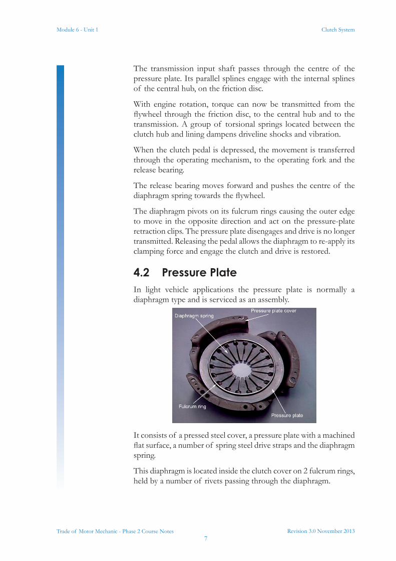
4.2 Pressure PlateIn light vehicle applications the pressure plate is normally a diaphragm type and is serviced as an assembly.
It consists of a pressed steel cover, a pressure plate with a machined flat surface, a number of spring steel drive straps and the diaphragm spring.
This diaphragm is located inside the clutch cover on 2 fulcrum rings, held by a number of rivets passing through the diaphragm.
Module 6 - Unit 1
Revision 3.0 November 20138
Clutch System
Trade of Motor Mechanic - Phase 2 Course Notes
The pressure plate is connected to the cover by the spring steel drive straps, riveted to the cover at one end and to projecting lugs on the plate, at the other.
Retraction clips hold the pressure plate in contact with the outer edge of the diaphragm. During clutch operation, they move the plate away from the flywheel.
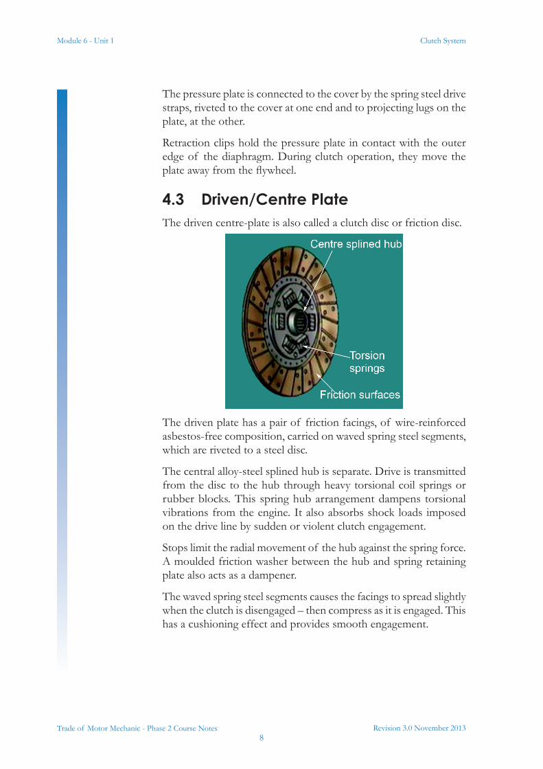
4.3 Driven/Centre PlateThe driven centre-plate is also called a clutch disc or friction disc.
The driven plate has a pair of friction facings, of wire-reinforced asbestos-free composition, carried on waved spring steel segments, which are riveted to a steel disc.
The central alloy-steel splined hub is separate. Drive is transmitted from the disc to the hub through heavy torsional coil springs or rubber blocks. This spring hub arrangement dampens torsional vibrations from the engine. It also absorbs shock loads imposed on the drive line by sudden or violent clutch engagement.
Stops limit the radial movement of the hub against the spring force. A moulded friction washer between the hub and spring retaining plate also acts as a dampener.
The waved spring steel segments causes the facings to spread slightly when the clutch is disengaged – then compress as it is engaged. This has a cushioning effect and provides smooth engagement.

Revision 3.0 November 20139
Module 6 - Unit 1 Clutch System
Trade of Motor Mechanic - Phase 2 Course Notes
4.4 Clutch Release Bearing (Throw-out Bearing)
The clutch release bearing can be a thrust-type angular contact ball bearing, supported on a carrier. It slides on a hub or sleeve extending from the front of the transmission.
The bearing carrier locates on the clutch release fork. Moving the fork brings the bearing thrust face into contact with the pressure plate fingers. This causes the bearing to rotate and absorb the rotary motion of the fingers, against the linear motion of the fork. The bearing is packed with lubricant during manufacture and requires no periodic maintenance during its service life.
Module 6 - Unit 1
Revision 3.0 November 201310
Clutch System
Trade of Motor Mechanic - Phase 2 Course Notes
5.0 Friction Principles of the Clutch System
5.1 Friction
Overview
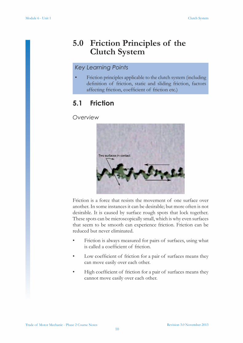
Friction is a force that resists the movement of one surface over another. In some instances it can be desirable; but more often is not desirable. It is caused by surface rough spots that lock together. These spots can be microscopically small, which is why even surfaces that seem to be smooth can experience friction. Friction can be reduced but never eliminated.
• Friction is always measured for pairs of surfaces, using what is called a coefficient of friction.
• Low coefficient of friction for a pair of surfaces means they can move easily over each other.
• High coefficient of friction for a pair of surfaces means they cannot move easily over each other.
Key Learning Points• Friction principles applicable to the clutch system (including
definition of friction, static and sliding friction, factors affecting friction, coefficient of friction etc.)
Revision 3.0 November 201311
Module 6 - Unit 1 Clutch System
Trade of Motor Mechanic - Phase 2 Course Notes
Coefficient of FrictionThe coefficient of friction (also known as the frictional coefficient or the friction coefficient) is a scalar value used to calculate the force of friction between two bodies. The coefficient of friction depends on the materials used -- for example, ice on metal has a very low coefficient of friction (they rub together very easily), while rubber on pavement has a very high coefficient of friction (they do not rub together easily). It is interesting to note that, contrary to common belief, the force of friction is invariant to the size of the contact area between the two objects. This means that friction does not depend on the size of the objects.
The force of friction is always exerted in a direction that opposes movement. For example, a chair sliding to the right across a floor experiences the force of friction in the left direction.
Types of FrictionStatic friction occurs when the two objects are not moving relative to each other (like a desk on the ground). The coefficient of static friction is typically denoted as μ. The initial force to get an object moving is often dominated by static friction.
Kinetic friction occurs when the two objects are moving relative to each other and rub together (like a sled on the ground). The coefficient of kinetic friction is typically denoted as μ and is usually less than the coefficient of static friction. Examples of kinetic friction:
Static Friction
Kinetic Friction
Module 6 - Unit 1
Revision 3.0 November 201312
Clutch System
Trade of Motor Mechanic - Phase 2 Course Notes
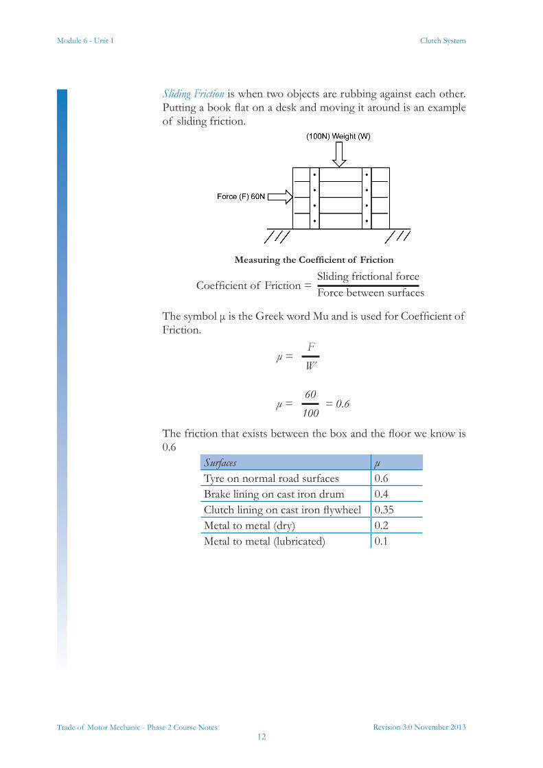
Sliding Friction is when two objects are rubbing against each other. Putting a book flat on a desk and moving it around is an example of sliding friction.
MeasuringtheCoefficientof Friction
Sliding frictional forceForce between surfacesCoefficient of Friction =
The symbol μ is the Greek word Mu and is used for Coefficient of Friction.
The friction that exists between the box and the floor we know is 0.6
FW
μ =
= 0.660100
μ =
Surfaces μTyre on normal road surfaces 0.6Brake lining on cast iron drum 0.4Clutch lining on cast iron flywheel 0.35Metal to metal (dry) 0.2Metal to metal (lubricated) 0.1
Revision 3.0 November 201313
Module 6 - Unit 1 Clutch System
Trade of Motor Mechanic - Phase 2 Course Notes
6.0 The Dual Mass Flywheel
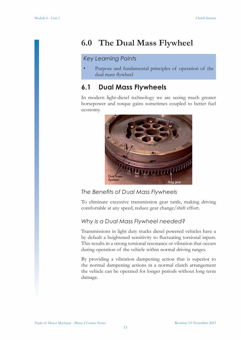
6.1 Dual Mass FlywheelsIn modern light-diesel technology we are seeing much greater horsepower and torque gains sometimes coupled to better fuel economy.
The Benefits of Dual Mass FlywheelsTo eliminate excessive transmission gear rattle, making driving comfortable at any speed, reduce gear change/shift effort.
Why is a Dual Mass Flywheel needed?Transmissions in light duty trucks diesel powered vehicles have a by default a heightened sensitivity to fluctuating torsional inputs. This results in a strong torsional resonance or vibration that occurs during operation of the vehicle within normal driving ranges.
By providing a vibration dampening action that is superior to the normal dampening actions in a normal clutch arrangement the vehicle can be operated for longer periods without long term damage.
Key Learning Points• Purpose and fundamental principles of operation of the
dual mass flywheel

Module 6 - Unit 1
Revision 3.0 November 201314
Clutch System
Trade of Motor Mechanic - Phase 2 Course Notes
The dual mass flywheel construction relocates the damper from the driven disc to the engine flywheel. This repositioning dampens engine torsional vibrations more than is possible with standard clutch disc dampening technology.
Function and OperationThe function of the Dual Mass Flywheels or DMF is to isolate torsion crankshaft spikes created by diesel engines with high compression ratios. By eliminating the torsion spikes, the system eliminates any potential damage to the transmission gear teeth. If the DMF was not used the torsional frequencies could damage to the transmission.
Revision 3.0 November 201315
Module 6 - Unit 1 Clutch System
Trade of Motor Mechanic - Phase 2 Course Notes
7.0 Cable/Hydraulic Clutch Release Operating Mechanisms
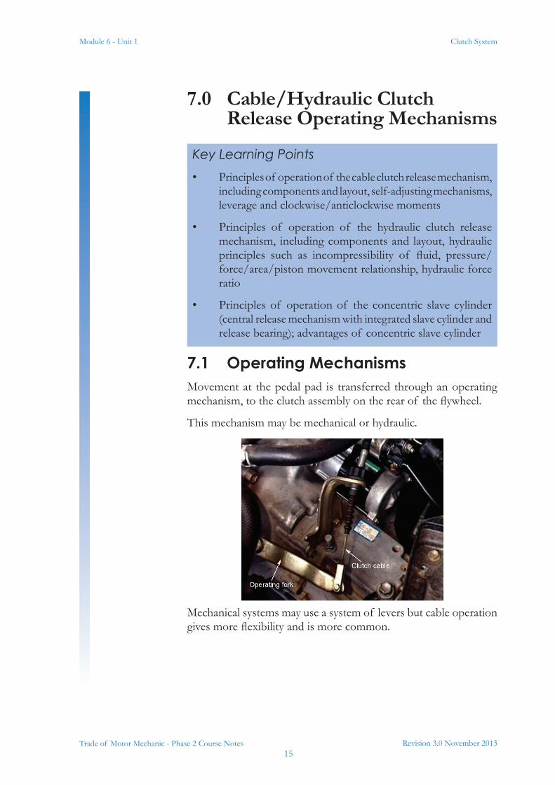
7.1 Operating MechanismsMovement at the pedal pad is transferred through an operating mechanism, to the clutch assembly on the rear of the flywheel.
This mechanism may be mechanical or hydraulic.
Mechanical systems may use a system of levers but cable operation gives more flexibility and is more common.
Key Learning Points• Principles of operation of the cable clutch release mechanism,
including components and layout, self-adjusting mechanisms, leverage and clockwise/anticlockwise moments
• Principles of operation of the hydraulic clutch release mechanism, including components and layout, hydraulic principles such as incompressibility of fluid, pressure/force/area/piston movement relationship, hydraulic force ratio
• Principles of operation of the concentric slave cylinder (central release mechanism with integrated slave cylinder and release bearing); advantages of concentric slave cylinder
Module 6 - Unit 1
Revision 3.0 November 201316
Clutch System
Trade of Motor Mechanic - Phase 2 Course Notes
In hydraulic clutch control, the pedal acts on a master cylinder, connected by a hydraulic pipe and flexible hose, to a slave cylinder, mounted on the clutch housing. The slave cylinder operates the clutch release fork. With clutch hydraulic systems it is important that no air is in the system as this will compress and not allow pressure to the transmitted to the clutch release fork. Therefore it is important to bleed the system and this should be done using manufactures procedures.
7.2 Associated Science and Maths
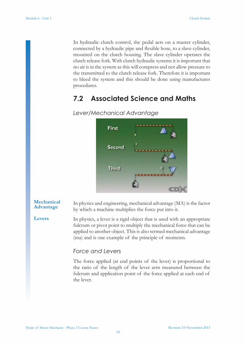
Lever/Mechanical Advantage
In physics and engineering, mechanical advantage (MA) is the factor by which a machine multiplies the force put into it.
In physics, a lever is a rigid object that is used with an appropriate fulcrum or pivot point to multiply the mechanical force that can be applied to another object. This is also termed mechanical advantage (ma) and is one example of the principle of moments.
Force and LeversThe force applied (at end points of the lever) is proportional to the ratio of the length of the lever arm measured between the fulcrum and application point of the force applied at each end of the lever.
Mechanical Advantage
Levers
Revision 3.0 November 201317
Module 6 - Unit 1 Clutch System
Trade of Motor Mechanic - Phase 2 Course Notes
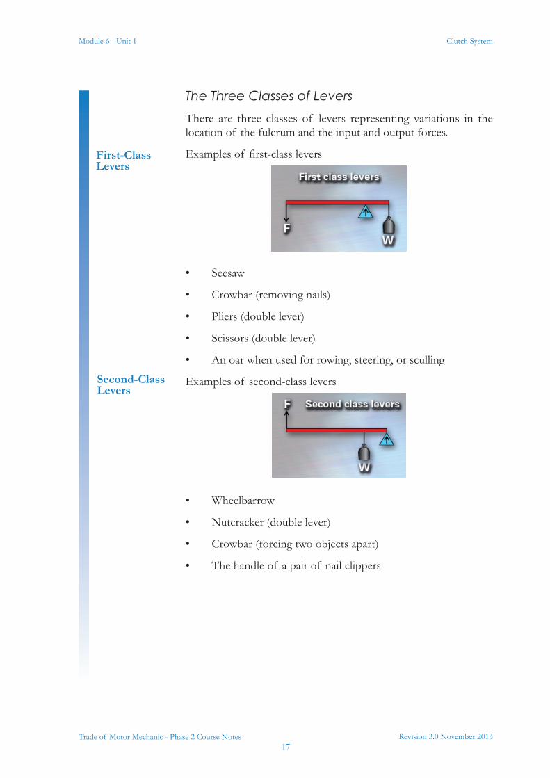
The Three Classes of LeversThere are three classes of levers representing variations in the location of the fulcrum and the input and output forces.
Examples of first-class levers
• Seesaw
• Crowbar (removing nails)
• Pliers (double lever)
• Scissors (double lever)
• An oar when used for rowing, steering, or sculling
Examples of second-class levers
• Wheelbarrow
• Nutcracker (double lever)
• Crowbar (forcing two objects apart)
• The handle of a pair of nail clippers
First-Class Levers
Second-Class Levers
Module 6 - Unit 1
Revision 3.0 November 201318
Clutch System
Trade of Motor Mechanic - Phase 2 Course Notes
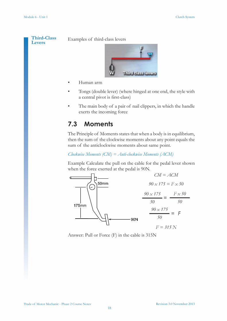
Examples of third-class levers
• Human arm
• Tongs (double lever) (where hinged at one end, the style with a central pivot is first-class)
• The main body of a pair of nail clippers, in which the handle exerts the incoming force
7.3 MomentsThe Principle of Moments states that when a body is in equilibrium, then the sum of the clockwise moments about any point equals the sum of the anticlockwise moments about same point.
Clockwise Moments (CM) = Anti-clockwise Moments (ACM)
Example Calculate the pull on the cable for the pedal lever shown when the force exerted at the pedal is 90N.
Answer: Pull or Force (F) in the cable is 315N
Third-Class Levers
CM = ACM
90 x 175 = F x 50
F = 315 N
90 x 17550
F x 5050
=
90 x 17550
= F
Revision 3.0 November 201319
Module 6 - Unit 1 Clutch System
Trade of Motor Mechanic - Phase 2 Course Notes
7.4 Hydraulic Pressure & Force
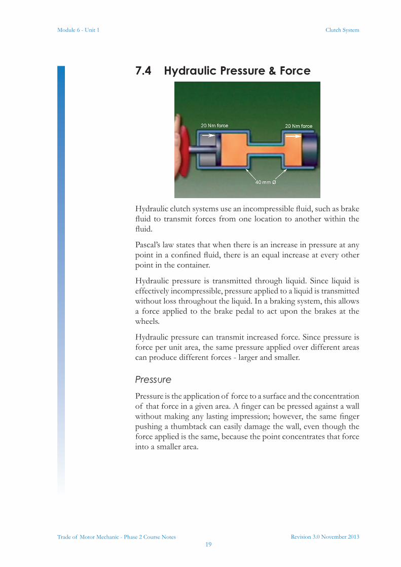
Hydraulic clutch systems use an incompressible fluid, such as brake fluid to transmit forces from one location to another within the fluid.
Pascal’s law states that when there is an increase in pressure at any point in a confined fluid, there is an equal increase at every other point in the container.
Hydraulic pressure is transmitted through liquid. Since liquid is effectively incompressible, pressure applied to a liquid is transmitted without loss throughout the liquid. In a braking system, this allows a force applied to the brake pedal to act upon the brakes at the wheels.
Hydraulic pressure can transmit increased force. Since pressure is force per unit area, the same pressure applied over different areas can produce different forces - larger and smaller.
PressurePressure is the application of force to a surface and the concentration of that force in a given area. A finger can be pressed against a wall without making any lasting impression; however, the same finger pushing a thumbtack can easily damage the wall, even though the force applied is the same, because the point concentrates that force into a smaller area.
Module 6 - Unit 1
Revision 3.0 November 201320
Clutch System
Trade of Motor Mechanic - Phase 2 Course Notes
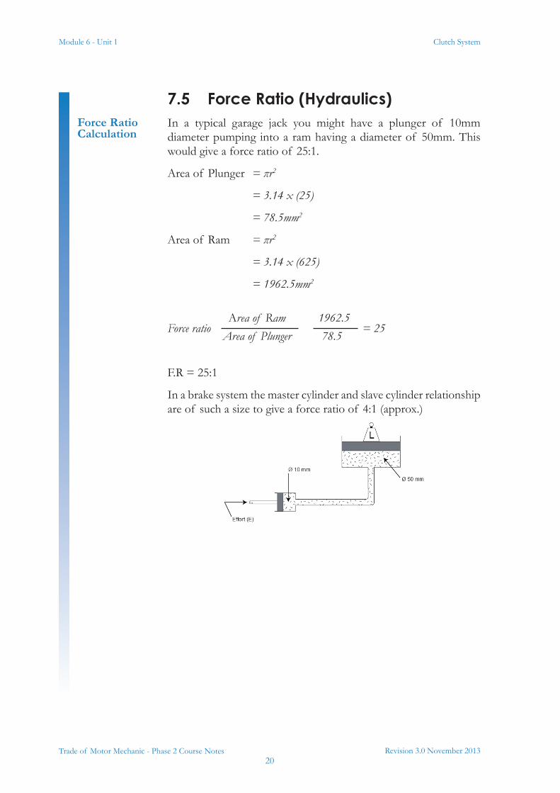
7.5 Force Ratio (Hydraulics)In a typical garage jack you might have a plunger of 10mm diameter pumping into a ram having a diameter of 50mm. This would give a force ratio of 25:1.
Area of Plunger = πr2
= 3.14 x (25)
= 78.5mm2
Area of Ram = πr2
= 3.14 x (625)
= 1962.5mm2
Force ratio = 25
F.R = 25:1
In a brake system the master cylinder and slave cylinder relationship are of such a size to give a force ratio of 4:1 (approx.)
Force Ratio Calculation
Area of RamArea of Plunger
1962.578.5
Revision 3.0 November 201321
Module 6 - Unit 1 Clutch System
Trade of Motor Mechanic - Phase 2 Course Notes
8.0 Clutch Pedal Leverage Ratio
Example in 7.3
9.0 RemovingandRefittingaClutch Cable
This is a practical task. Please refer to your instructor for additional information, which is available from the automotive technical manuals.
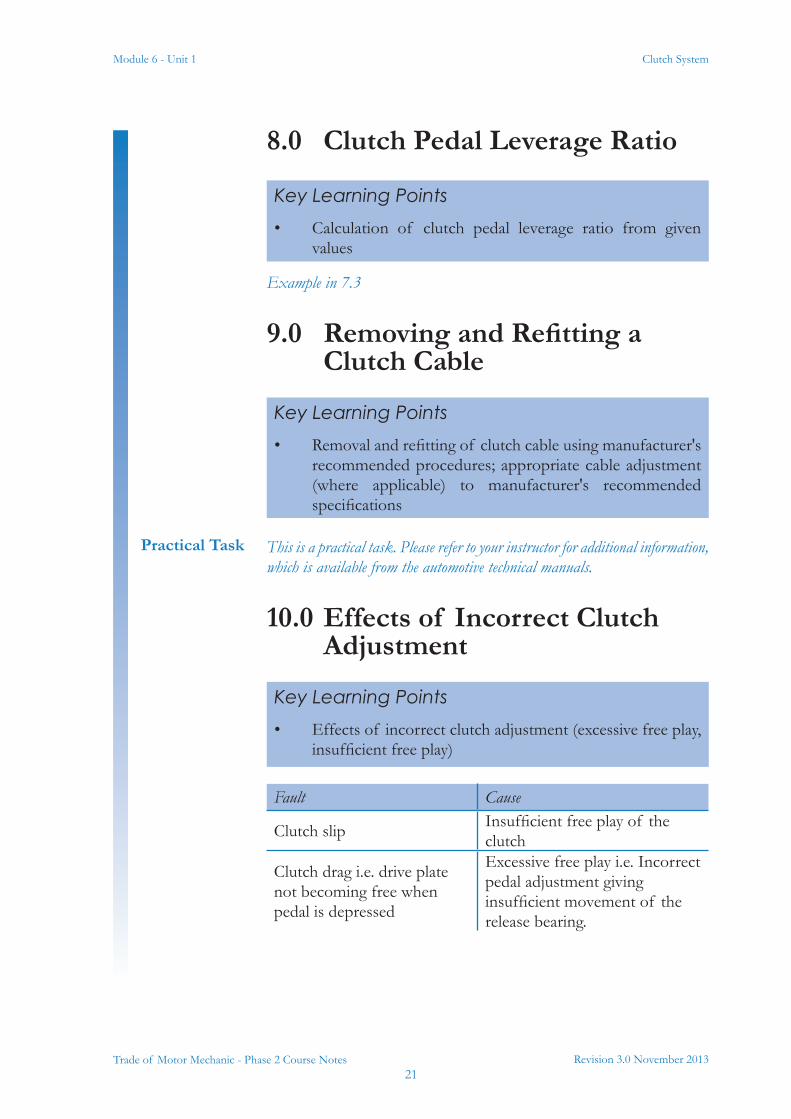
10.0 Effects of Incorrect Clutch Adjustment
Fault Cause
Clutch slip Insufficient free play of the clutch
Clutch drag i.e. drive plate not becoming free when pedal is depressed
Excessive free play i.e. Incorrect pedal adjustment giving insufficient movement of the release bearing.
Key Learning Points• Calculation of clutch pedal leverage ratio from given
values
Key Learning Points• Removal and refitting of clutch cable using manufacturer's
recommended procedures; appropriate cable adjustment (where applicable) to manufacturer's recommended specifications
Practical Task
Key Learning Points• Effects of incorrect clutch adjustment (excessive free play,
insufficient free play)
Module 6 - Unit 1
Revision 3.0 November 201322
Clutch System
Trade of Motor Mechanic - Phase 2 Course Notes
11.0 Factors Affecting Torque Transmission
11.1 Factors Affecting Torque Transmission
For a clutch to transmit torque without slip there are four factors to be considered.
• Number of surfaces S.
• Total spring pressure P.
• Coefficient of Friction μ pronounced “mew”.
• Mean radius r.
Known as S p μ r
Key Learning Points• Factors affecting torque transmission (number of friction
surfaces, spring pressure, coefficient of friction, effective radius of friction lining)
Revision 3.0 November 201323
Module 6 - Unit 1 Clutch System
Trade of Motor Mechanic - Phase 2 Course Notes
12.0 Maximum Torque Transmitted by a Single Plate Clutch
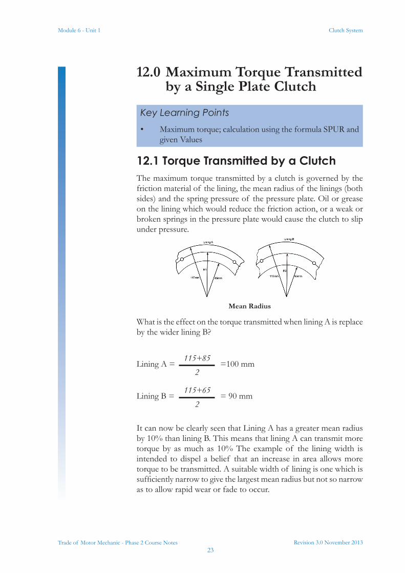
12.1 Torque Transmitted by a ClutchThe maximum torque transmitted by a clutch is governed by the friction material of the lining, the mean radius of the linings (both sides) and the spring pressure of the pressure plate. Oil or grease on the lining which would reduce the friction action, or a weak or broken springs in the pressure plate would cause the clutch to slip under pressure.
Mean Radius
What is the effect on the torque transmitted when lining A is replace by the wider lining B?
Lining A = =100 mm
Lining B = = 90 mm
It can now be clearly seen that Lining A has a greater mean radius by 10% than lining B. This means that lining A can transmit more torque by as much as 10% The example of the lining width is intended to dispel a belief that an increase in area allows more torque to be transmitted. A suitable width of lining is one which is sufficiently narrow to give the largest mean radius but not so narrow as to allow rapid wear or fade to occur.
Key Learning Points• Maximum torque; calculation using the formula SPUR and
given Values
115+852
115+652
Module 6 - Unit 1
Revision 3.0 November 201324
Clutch System
Trade of Motor Mechanic - Phase 2 Course Notes
12.2 Factors Affecting Torque Transmission Calculation
For a clutch to transmit torque without slip there are four factors to be considered.
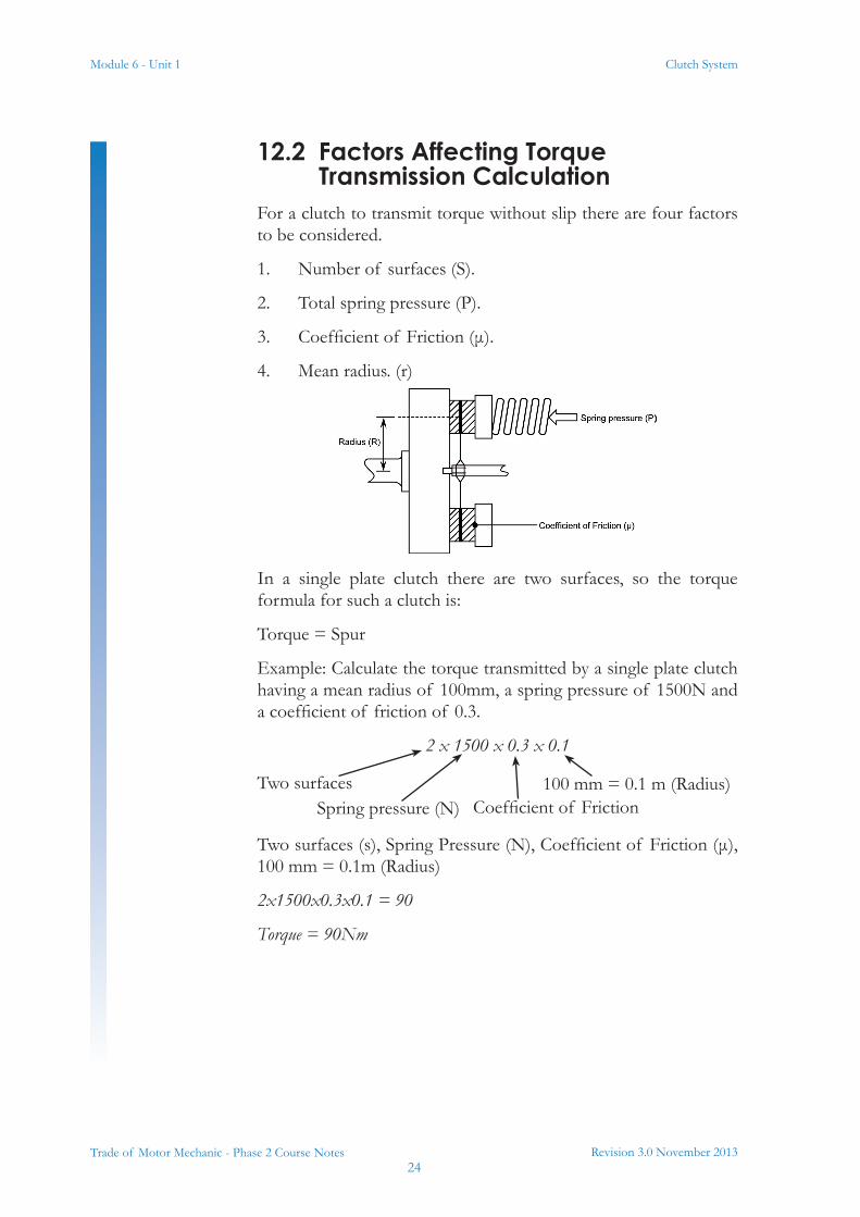
1. Number of surfaces (S).
2. Total spring pressure (P).
3. Coefficient of Friction (μ).
4. Mean radius. (r)
In a single plate clutch there are two surfaces, so the torque formula for such a clutch is:
Torque = Spur
Example: Calculate the torque transmitted by a single plate clutch having a mean radius of 100mm, a spring pressure of 1500N and a coefficient of friction of 0.3.
2 x 1500 x 0.3 x 0.1
Two surfaces (s), Spring Pressure (N), Coefficient of Friction (μ), 100 mm = 0.1m (Radius)
2x1500x0.3x0.1 = 90
Torque = 90Nm
Two surfacesSpring pressure (N) Coefficient of Friction
100 mm = 0.1 m (Radius)
Revision 3.0 November 201325
Module 6 - Unit 1 Clutch System
Trade of Motor Mechanic - Phase 2 Course Notes
13.0 Common Clutch Faults
13.1 Causes of Common FaultsFault Cause
Clutch slip
Worn Lining.
Insufficient free-play of the clutch pedal.
Oil or grease on friction linings
Weak pressure plate Springs.
Excessive scores on flywheel face due to Worn lining.
Clutch drag i.e. drive plate not becoming free when pedal is depressed
Distorted drive plate.
Incorrect pedal adjustment giving insufficient movement of the release bearing.
Oil or grease on friction lining.
Drive plate (clutch Disc) seized on the splines.
Broken release levers.
Clutch judder
Worn lining or protruding rivets.
Oil on the linings.
Distorted drive plate.
Loose engine or gearbox Mountings or slack tie rods.
Key Learning Points• Common clutch faults and their related symptoms and
causes clutch slip, drag
Module 6 - Unit 1
Revision 3.0 November 201326
Clutch System
Trade of Motor Mechanic - Phase 2 Course Notes
14.0 Servicing Clutch System Components
This is a practical task. Please refer to your instructor for additional information, which is available from the automotive technical manuals.
15.0 Bleeding a Hydraulic Clutch System
This is a practical task. Please refer to your instructor for additional information, which is available from the automotive technical manuals.
Key Learning Points• Removal, examination and refitting/replacement of clutch
pressure plate, disc and release bearing using manufacturer's recommended procedures
Practical Task
Key Learning Points• Clutch hydraulic system bleeding using manufacturer's
recommended procedures
• Use of data manuals/manufacturer's manuals
Practical Task
Revision 3.0 November 201327
Module 6 - Unit 1 Clutch System
Trade of Motor Mechanic - Phase 2 Course Notes
Self AssessmentQ1: What is the purpose of the spring steel segments in the clutch centre plate? (Tick one box only) 1. To provide a cushioning effect during engagement of the
clutch
2. To act as a link between the two centre plate surfaces
3. To hold the two centres plate surfaces apart
4. To provide a cushioning effect during disengagement of the clutch
Q2: In the clutch operating mechanism, the purpose of an adjuster (when one is provided) is to ensure: (Tick one box only) 1. The release bearing engages the release levers at all times
2. The release fork contacts the release bearing at all times
3. Pedal height can be varied to suit the driver
4. A clearance can be set in the operating mechanism
Q3: The driving member of a clutch assembly is the: (Tick one box only) 1. Pressure plate
2. Face of the flywheel
3. Clutch disc
4. Transmission input shaft
Q4: The clutch pedal operates the master cylinder in a hydraulic system. This in turn operates the: ( Tick one box only) 1. Clutch cylinder
2. Wheel cylinder
3. Slave cylinder
4. Pushrod cylinder
Module 6 - Unit 1
Revision 3.0 November 201328
Clutch System
Trade of Motor Mechanic - Phase 2 Course Notes
Q5: When the clutch is disengaged, the diaphragm spring: (Tick one box only) 1. Expands
2. Contracts
3. Flattens
4. Dishes inward
Q6: Increasing the diameter of a single-plate clutch increases the maximum: (Tick one box only) 1. Centrifugal force the clutch can withstand
2. Torque the clutch can transmit
3. Power the clutch can transmit
4. Engine speed before clutch slip
Q7: The purpose of the clutch is to transmit: (Tick one box only) 1. Power from the transmission input shaft to the engine
2. Power from the engine to the transmission input shaft
3. Torque from the engine to the transmission input shaft
4. Torque from the transmission input shaft to the engine
Q8: Select the correct option to complete the statement. The engine supplies a twisting or rotating force called_________, which ultimately turns the vehicles’ wheels and propels the vehicle. (Tick one box only) 1. Newton’s
2. Torque
3. Horsepower
4. Ratio

Revision 3.0 November 201329
Module 6 - Unit 1 Clutch System
Trade of Motor Mechanic - Phase 2 Course Notes
Suggested Exercises1. Use an electronic data facility to procure manufacturer’s
appropriate data for use with practical exercises
2. Remove and refit a clutch cable
3. Remove, examine and refit/replace clutch system components
4. Bleed a hydraulic clutch system
Training Resources• Training vehicles training units, data manuals, manufacturer's
manuals, video/ multimedia resources
• Selection of clutch system mechanical and hydraulic components (including pressure plates, clutch discs, release bearings, clutch pedal and pedal box, clutch master and slave cylinders, concentric slave cylinders, dual mass flywheels etc.)
• Torque spanners, clutch alignment tools, trolley jacks, transmission jacks, axle stands, eye protection, latex gloves, face masks, gear oil, sealed supply of appropriate clutch fluids etc.
Module 6 - Unit 1
Revision 3.0 November 201330
Clutch System
Trade of Motor Mechanic - Phase 2 Course Notes
Suggested Further Reading• Advanced Automotive Diagnosis. Tom Denton. ISBN
0340741236
• Automobile Electrical and Electronic Systems (3rd Edition). Tom Denton. ISBN 0750662190
• Automotive Mechanics (10th Edition). William H. Crouse and Donald L. Anglin. ISBN 0028009436
• Bosch Automotive Electrics Automotive Electronics: Systems and Components (4th Edition). Robert Bosch. ISBN 0837610508
• Bosch Automotive Handbook (6th Edition). Robert Bosch. ISBN 1860584748
• Bosch Automotive Technology Technical Instruction booklet series (numerous titles)
• Hillier’s Fundamentals of Motor Vehicle Technology: Book One (5th Edition). V.A.W. Hillier and Peter Coombes. ISBN 0748780823
• Hillier’s Fundamentals of Motor Vehicle Technology: Book Two (5th Edition). V.A.W. Hillier and Peter Coombes. ISBN 0748780998
• Modern Automotive Technology. James E. Duffy. ISBN 1566376106
• Motor Vehicle Craft Studies - Principles. F.K. Sully. ISBN 040800133X
• National Car Test (NCT) Manual (Department of Transport, Vehicle Testers Manual - DoT VTM). Department of Transport
• Transmission, Chassis and Related Systems (Vehicle Maintenance and Repair Series: Level 3) (3rd Edition) John Whipp and Roy Brooks. ISBN 186152806X
• Vehicle and Engine Technology (2nd Edition). Heinz Heisler. ISBN 0340691867
• http://www.cdxglobal.com/
• http://auto.howstuffworks.com/
• http://www.autoshop101.com/
• http://www.cdxetextbook.com/
• Automotive Encyclopedia and Text Book Resource (CD version of e-textbook), Available from your instructor.

Notes


27-33 Upper Baggot Street
Dublin 4