tq basetravel 401 801 us - torqeedo spares and accessories
TRANSCRIPT

BaseTravel 401 SBaseTravel 401 LBaseTravel 801 SBaseTravel 801 LOperating Manual(English)


�Operating Manual BaseTravel 401/801
1. Contents
1. Contents
2. Important safety and handling instructions 4
�. Introduction 6
4. About this instruction manual 7
5. Conformity declaration 7
6. Warranty conditions 8 6.1 Extent of warranty 8 6.2 Warranty process 9
7. Equipment and operating elements 10 7.1 Supply scope 10 7.2 Plan of operating elements 11
8. Starting up 12 8.1 Assembly of the drive 12 8.2 Basic information on battery supply 12 8.� Connecting the BaseTravel 401 to lead batteries (acid, gel, AGM) 14 8.4 Connecting the BaseTravel 801 to lead batteries (acid, gel, AGM) 16 8.5 Connecting the BaseTravel 801 to a Torqeedo Power 26-77 lithium-manganese battery 17 8.6 Connecting the BaseTravel 401 and 801 to lithium-manganese replacement batteries from the Torqeedo Travel series 18 8.7 Fitting the outboard motor to the boat 18
9. Operation 20 9.1 Transom bracket 20 9.2 Tiller 20 9.� Pylon 22 9.4 Battery adapter cable set including fuse 2� 9.5 Optimum submergence depth and travel behaviour 24
10. Dismantling 25
11. Storage and care instructions 25 11.1 Corrosion protection 25 11.2 Other care instructions 26
12. Trouble shooting 27
1�. Technical data 28
14. Disposal instructions 29
15. Accessories 29
16. Torqeedo Service Centers �2

4 Operating Manual BaseTravel 401/801
2. Important safety and operating instructions
Important safety instructions
Torqeedo motors are designed to operate safely and reliably as long as they are used according to the operating manual. Please read this manual carefully before you start the motor. Ignoring these instructions can cause property damage or personal injury. Torqeedo accepts no liability for damage caused by actions that contradict this operating manual.
To ensure safe operation of the motor:
• Familiarize yourself with all the motor controls. You should be able to stop the motor quickly if necessary.
• If you link together several batteries for the power supply of your BaseTravel, always ensure you only combine similar batteries (the same capacity, same age, same manufacturer, same charge condition). Different charge conditions between batteries linked together can, when the batteries are linked up, lead to extremely high compensating currents or overloading that overload cables and plugs or the battery itself. In extreme cases, this can cause fires and injuries. Therefore always follow the instructions in section 8.2 to 8.5 of this operating manual.
• The cable cross-section for battery link-ups must be at least 6mm2.• Only allow adults who have been instructed on how to operate the motor or have
read the operating instructions to run it. • Follow the boat manufacturer‘s instructions on the permissible motorisation of your
boat. Do not exceed the capacity limits. • Stop the engine immediately if someone goes overboard.• Do not run the motor if someone is in the water near the boat.• Do not use the motor as a lashing point for your boat. Do not use the motor as a
handle for lifting or carrying smaller boats • Do not submerge the battery adapter cable set in water or other liquids.

5Operating Manual BaseTravel 401/801
2. Important safety and operating instructions
Important operating instructions
Here are the most important instructions on operating Torqeedo BaseTravel Motors. Apart from these instructions, please observe the complete operating instructions to prevent damage to your motor.
• Only run the motor when the propeller is under water. If it is run in the air, the shaft sealant rings that seal the motor to the drive shaft may become damaged. If the motor is run in the air for a longer period, the motor itself can overheat.
• When mounted, the battery adapter cable set is protected against rain and spray water. Do not submerge it and keep the contacts dry. If water enters the battery adapter via the contacts, this can cause irreparable damage to the electronics. If liquid has entered the battery, first drain off the liquid through the adapter openings. Then dry it in a dry, warm environment up to a maximum of 80°C before you use it again.
• After use, remove the battery adapter from the shaft head. This completely cuts the power supply to the motor and prevents the batteries from discharging during storage.
• After use, always take the motor out of the water. You can do this using the tilt mecha-nism of the transom mount.
• After use in salt or brackish water, rinse the motor (but never the adapter) with fresh water.
• Occasionally use contact spray to care for the adapter contacts, the shaft head contacts and the steering cable plug. If you use the motor in salt or brackish water, we recommend applying contact spray once a month.
• Only store the motor in a dry condition. • If the motor malfunctions, first switch the tiller control to the stop position for approx.
2 seconds. The stop setting has a reset function and may correct minor faults itself.• If you have a problem with your motor, please follow the instructions in this manual for
handling warranty claims.

6 Operating Manual BaseTravel 401/801
3. Introduction
Dear customer,
We are delighted that you have chosen our motor. In terms of drive technology and efficiency, your Torqeedo BaseTravel outboard motor is cutting-edge technology It has been designed and manufactured with the utmost care and with a special focus on comfort, user-friendliness and safety, then exhaustively tested before delivery.
Please take the time to read these operating instructions carefully so that you can use the motor properly and enjoy it for a long time.
We constantly strive to improve Torqeedo products. Should you have any comments on the design and use of our products, we would be pleased to hear from you. Please contact our Customer Services if you have any questions on Torqeedo products ([email protected]).
We hope you have a lot of fun with this product.
Yours,
Dr. Friedrich Böbel Dr. Christoph BallinGeschäftsführender Gesellschafter Geschäftsführender Gesellschafter

7Operating Manual BaseTravel 401/801
3. Introduction 4. About this instruction manual 5. Conformity declaration
4. About this instruction manual
This instruction manual will help you use your Torqeedo BaseTravel 401/801 safely and efficiently. All information is given according to our latest knowledge. Subject to technical changes.
• Highlights a danger or process which could lead to injury or property damage
• Highlights a danger or process which could lead to property damage
5. Conformity declaration
We, Torqeedo GmbH, with sole responsibility, declare the conformity of the BaseTravel 401/801 product range with the following provisions:
Small water vehicles Electrical systems Low-voltage direct current (DC) systemsDIN EN ISO 101��:2000
Starnberg, February 2007
Managing Director‘s signature
The aforementioned company holds the following technical documents available for viewing: - Required operating manual - Plans/software source code (EU authorities only) - Inspection records (EU authorities only) - Other technical documentation (EU authorities only)

8 Operating Manual BaseTravel 401/801
6. Warranty conditions
6.1 Extent of warranty
Torqeedo GmbH, Petersbrunner Straße �a in D-82�19 Starnberg, Germany, guarantees the final purchaser of a Torqeedo outboard motor that the product is free from material and manufacturing faults during the period stated below. Torqeedo will indemnify the final purchaser for any expense for the repair of a material or manufacturing fault. This indemnification obligation does not cover the incidental costs of a warranty claim or any other financial losses (e.g. costs for towing, telecommunications, food, accommodation, loss of earnings, loss of time etc.).
The warranty ends two years after the date on which the product was delivered to the final purchaser. Products that are used commercially or by public authorities - even if only temporarily - are excluded from this two-year warranty. In these cases, the statutory warranty applies. The right to claim under warranty runs out six months after discovery of a fault.
Torqeedo decides whether faulty parts are repaired or replaced. Distributors and dealers who repair Torqeedo motors have no authority to make legally binding statements on behalf of Torqeedo.
Normal wear and tear and routine servicing are excluded from the warranty.
Torqeedo is entitled to refuse a warranty claim if • the warranty was not correctly submitted (especially failure to contact Torqeedo before
sending back goods, failure to present a completely filled-in warranty certificate and proof of purchase, see Warranty process),
• the product was not treated in accordance with the instructions• the safety, operating and care instructions in the manual were not observed• the product was in any way altered or modified or parts and accessories were added that
are not expressly permitted or recommended by Torqeedo• previous services or repairs were not carried out by firms authorized by Torqeedo, or
non-original parts were used unless the consumer can prove that the facts that led to the warranty being void did not affect the development of the fault.

9Operating Manual BaseTravel 401/801
As well as the rights arising from this warranty, the customer also has legal warranty claim rights arising from the purchase contract with the dealer which are not hampered by this warranty.
6.2 Warranty process
Adhering to the following warranty process is a prerequisite to the satisfaction of any warranty claims.
Before dispatching any apparently faulty goods, it is imperative to coordinate the delivery with Torqeedo Services. You can contact us by phone, email or post. You can find the contact details on the back of this manual. Please note that we are unable to deal with pro-ducts of which we have not been notified and will therefore refuse to accept delivery.
To check a warranty claim and to process a warranty, we require a completed warranty certificate as well as proof of purchase.• The warranty certificate attached to this operating manual must show contact details,
product details, serial number and a brief description of the problem.• Proof of purchase must indicate the purchase and the date of purchase (e.g. till receipt,
invoice or receipt).
For returning the motor to the Service Centre, we recommend keeping the original Torqeedo packaging.
We are available to answer any questions regarding the warranty process - simply use the details on the back cover.
6. Warranty conditions

10 Operating Manual BaseTravel 401/801
7. Equipment and operating elements
7.1 Supply scope
The full supply scope of your Torqeedo BaseTravel should include the following parts:
• Shaft assembly group• Transom bracket assembly group• Tiller assembly group• Battery adapter cable set assembly group• Connection cable for serial connection of two 12 V batteries (only for BaseTravel 801)• Tiller handle• 2 bolts (for fixing the battery adapter cable set)• 2 on/off pins • Allen key• Operating instructions• Warranty certificate• Packaging

11Operating Manual BaseTravel 401/801
7.2 Plan of operating elements
7. Equipment and operating elements
Tension screw (to fit the folding shaft)
Shaft head
Assembly group batteryOn/off pin (to turn off the engine)
Tiller handle Assembly group tiller
Bolt (to fit the battery to the shaft)
Cable duct
Control cable
Opening button(to change the
length of the tiller)
Dead bolt
Rest button (to tilt the engine)
Friction screw (to lock the steering)
Mounting clamp (to fit the engine to the boat)
Assembly group transom bracketAssembly group folding shaft
Propeller with sacrificial anode
Pylon
Fin
12 Operating Manual BaseTravel 401/801
8. Starting up
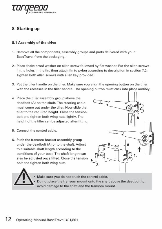
8.1 Assembly of the drive
1. Remove all the components, assembly groups and parts delivered with your BaseTravel from the packaging.
2. Place shake proof washer on allen screw followed by flat washer. Put the allen screws in the holes in the fin, then attach fin to pylon according to description in section 7.2. Tighten both allen screws with allen key provided.
�. Put the tiller handle on the tiller. Make sure you align the opening button on the tiller with the recesses in the tiller handle. The opening button must click into place audibly.
4. Place the tiller assembly group above the deadbolt (A) on the shaft. The steering cable must come out under the tiller. Now slide the tiller to the required height. Close the tension bolt and tighten both wing nuts lightly. The height of the tiller can be adjusted after fitting.
5. Connect the control cable.
6. Push the transom bracket assembly group under the deadbolt (A) onto the shaft. Adjust to a suitable shaft length according to the conditions of your boat. The shaft length can also be adjusted once fitted. Close the tension bolt and tighten both wing nuts.
• Make sure you do not crush the control cable. • Do not place the transom mount onto the shaft above the deadbolt to
avoid damage to the shaft and the transom mount.
A
1.
2.
A

1�Operating Manual BaseTravel 401/801
8.2 Basic information on battery supply
The BaseTravel models can be operated with lead-acid, lead-gel, AGM or lithium-based batteries.
To calculate the travel time and range of the batteries, you need to know the battery capacity. In the following, this is stated in watt-hours (Wh). The number of watt-hours can easily be matched with the input power of the motors (in W): A BaseTravel 801 with an input power of 800 W consumes 800 Wh in one hour. The BaseTravel 401 consumes 400 Wh in one hour. The nominal capacity of a battery (Wh) is calculated by multiplying the charge (Ah) with the voltage (V). So a battery with 12 V and 70 Ah has a capacity of 840 Wh.
It is generally true for lead-acid, lead-gel and AGM batteries that the nominal capacity calculated in this way cannot be fully utilized. This is due to the limited heavy-current capacity of lead batteries. This effect is negligible for lithium-manganese batteries.
Decisive for the anticipated range and service lives of the batteries are not only the battery capacity actually available, but also the type of boat, the performance (shorter travel time and range at higher speeds) and in the case of lead batteries the ambient temperature.
The following table gives some examples of typical service lives.
8. Starting up
Model Battery supply Ambient tempera-ture
Speed category(see sec-tion 9.2)
Capacity actually available
Travel time in hours:minutes
BaseTravel 401
840 Wh, lead-gel (1 battery* 12 V, 70 Ah, approx. 22kg.
> + 10 °C Full speed
~ 680 Wh 1:40
BaseTravel 401
840 Wh, lead-gel (1 battery* 12 V, 70 Ah, approx. 22kg.
> + 10 °C Max. range
~ 820 Wh 16:20
BaseTravel 801
1,680 Wh, lead-gel (2 batteries*12 V, 70 Ah, approx. 44kg)
> + 10 °C Full speed
~ 1,�60 Wh 1:40
BaseTravel 801
1,680 Wh, lead-gel (2 batteries*12 V, 70 Ah, approx. 44kg)
> + 10 °C Max. range
~ 1,660 Wh 9:10
BaseTravel 801
1,994 Wh, lithium-manganese (1 Torqeedo Power 26-77, 18kg)
Between - 20 and + 45 °C
Full speed
~ 1,994 Wh 2:�0
BaseTravel 801
1,994 Wh, lithium-manganese (1 Torqeedo Power 26-77, 18kg)
Between - 20 and + 45 °C
Max. range
~ 1,994 Wh 40:00
* new, good quality

14 Operating Manual BaseTravel 401/801
We recommend that you achieve the required battery capacity in Wh using as few parallel connections as possible with as few batteries as possible. So, to create a battery capacity of for instance 2,400 Wh (at twelve volts), it is better to use one 12 V / 200 Ah battery instead of two parallel connected 12 V / 100 Ah batteries. Firstly, this avoids safety risks from battery configurations. And secondly, capacity differences between the batte-ries that already exist at the time of the configuration or that develop later have a negative effect on the overall battery system (capacity loss, also called drifting). Thirdly, this way you reduce losses at the contact points that can amount to 2-�% of the battery capacity.
To avoid safety risks, capacity losses and contact point losses with serial and parallel battery configurations, always only combine the same type of batteries (same capacity, same age, same manufacturer, same charge condition).
• Serial and parallel configured batteries must always have the same charge condition. That is why you must use only the same type of batteries in configurations (same capacity, same age, same manufacturer, same charge condition) and fully charge each battery separately in your charger before you connect it up. Different charge conditions between batteries linked together can, when the batteries are linked up, lead to extremely high compensating currents or overloading that overload cables and plugs or the battery itself. In extreme cases, this can cause fires and injuries.
8.3 Connecting the BaseTravel 401 to lead batteries (acid, gel, AGM)
The BaseTravel 401 operates with a power supply of between 10 V and 16.8 V. This means it can be operated with a 12 V lead-acid, lead-gel or AGM battery. To increase the capacity, you can configure several 12 V batteries parallel to each other.
To connect the BaseTravel 401 to a 12 V battery, connect the negative terminal clamp of the battery adapter cable set (identified by the label) to the negative pole of the battery. Then connect the positive terminal of the battery adapter cable set to the positive pole of the battery.
The cable set comes with a CF8 50 A fuse that protects the contact points from over- heating in case of short-circuiting. The battery adapter that can be removed from the shaft functions as the main battery switch of your drive.
15Operating Manual BaseTravel 401/801
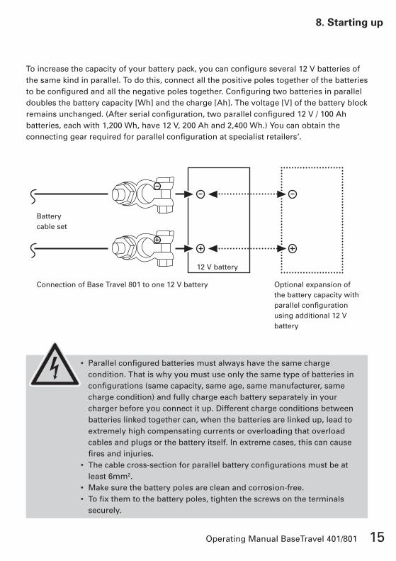
To increase the capacity of your battery pack, you can configure several 12 V batteries of the same kind in parallel. To do this, connect all the positive poles together of the batteries to be configured and all the negative poles together. Configuring two batteries in parallel doubles the battery capacity [Wh] and the charge [Ah]. The voltage [V] of the battery block remains unchanged. (After serial configuration, two parallel configured 12 V / 100 Ah batteries, each with 1,200 Wh, have 12 V, 200 Ah and 2,400 Wh.) You can obtain the connecting gear required for parallel configuration at specialist retailers‘.
• Parallel configured batteries must always have the same charge condition. That is why you must use only the same type of batteries in configurations (same capacity, same age, same manufacturer, same charge condition) and fully charge each battery separately in your charger before you connect it up. Different charge conditions between batteries linked together can, when the batteries are linked up, lead to extremely high compensating currents or overloading that overload cables and plugs or the battery itself. In extreme cases, this can cause fires and injuries.
• The cable cross-section for parallel battery configurations must be at least 6mm2.
• Make sure the battery poles are clean and corrosion-free.• To fix them to the battery poles, tighten the screws on the terminals
securely.
8. Starting up
Battery cable set
Connection of Base Travel 801 to one 12 V battery Optional expansion of the battery capacity with parallel configuration using additional 12 V battery
12 V battery

16 Operating Manual BaseTravel 401/801
8.4 Connecting the BaseTravel 801 to lead batteries (acid, gel, AGM)
The BaseTravel 801 operates with a power supply of between 20 V and ��.6 V. That means it can be operated with two serially configured 12 V lead-acid, lead-gel or AGM batteries. To increase the capacity, you can configure several pairs of serially connected 12 V batteries parallel to each other.
To connect the BaseTravel 801 to two 12 V batteries, connect the negative terminal clamp of the battery adapter cable set (identified by the label) to the negative pole of the first battery. Then use the connection cable provided to connect the positive pole of the first battery to the negative pole of the second battery. Finally, connect the positive terminal of the battery adapter cable set to the positive pole of the second battery.
Now the batteries are serially connected to each other: The battery capacity [Wh] and the voltage [V] of the battery block have been doubled. The battery charge [Ah] is not changed by serial configuration. (For instance: After serial configuration, two serially configured 12 V / 100 Ah batteries, each with 1,200 Wh, have 24 V, 100 Ah and 2,400 Wh.)
The cable set comes with a CF8 50 A fuse that protects the contact points from over- heating in case of short-circuiting. The battery adapter that can be removed from the shaft functions as the main battery switch of your drive.
To increase the capacity of your battery bank, you can connect several pairs of serially configured 12 V batteries with each other in a parallel configuration. Here again you must ensure that all the serial and parallel configured batteries are of the same type (same capacity, same age, same manufacturer, same charge condition).
• Serial and parallel configured batteries must always have the same charge condition. That is why you must use only the same type of bat-teries in configurations (same capacity, same age, same manufacturer, same charge condition) and fully charge each battery separately in your charger before you connect it up. Different charge conditions between batteries linked together can, when the batteries are linked up, lead to extremely high compensating currents or overloading that overload cables and plugs or the battery itself. In extreme cases, this can cause fires and injuries.
• The cable cross-section for battery configurations must be at least 6mm2.• Make sure the battery poles are clean and corrosion-free.• To fix them to the battery poles, tighten the screws on the terminals securely.

17Operating Manual BaseTravel 401/801
8.5 Connecting the BaseTravel 801 to a Torqeedo Power 26-77 lithium-manganese battery
The BaseTravel 801 operates with a power supply of between 20 V and ��.6 V. This means it can also be operated with a Torqeedo Power 26-77 lithium-manganese-based battery. To increase the capacity, you can configure several Torqeedo Power batteries parallel to each other.
To connect the BaseTravel 801 to a Torqeedo Power 26-77 battery, connect the negative terminal of the battery adapter cable set (identified by the label) to the negative pole of the battery. Then connect the positive terminal of the battery adapter cable set to the positive pole of the battery.
8. Starting up
Battery cable set
Connection of Base Travel 801 to two 12 V batteries Optional expansion of the battery capacity with parallel configuration using additional 12 V battery pairs
12 V battery
12 V battery

18 Operating Manual BaseTravel 401/801
The cable set comes with a CF8 50 A fuse that protects the contact points from over- heating in case of short-circuiting. The battery adapter that can be removed from the shaft functions as the main battery switch of your drive. Additionally, the Torqeedo Power battery features an integrated electronic master switch as well as a residual capacity display.
To increase the capacity using parallel configuration of several batteries, follow the same procedure as described under 8.� (parallel configuration of lead batteries for the BaseTravel 401).
• The cable cross-section for parallel battery configurations must be at least 6mm2.
• Make sure the battery poles are clean and corrosion-free.• To fix them to the battery poles, tighten the screws on the terminals
securely.
8.6 Connecting the BaseTravel 401 and 801 to lithium-manganese replacement batteries from the Torqeedo Travel series.
The BaseTravel 401 is compatible with the Travel 401 lithium-manganese replacement battery.
The BaseTravel 801 is compatible with the Travel 801 lithium-manganese replacement battery.
For power supply by Travel Series replacement batteries, the technical data of the Base-Travel models matches that of the corresponding Travel models.
8.7 Fitting the outboard motor to the boat
1. Suspend the drive in your boat and tighten the capstan-head screws. Ensure the weight is spread evenly in the boat.
2. Pull the stopper button on the transom mount and position the shaft vertical to the water level.

19Operating Manual BaseTravel 401/801
�. To adjust the shaft length, open both wing nuts on the transom bracket and fit the shaft length to your boat so that the propeller has the required submergence depth. Note that the submergence depth has a major influence on the efficiency of your drive. To optimize the submergence depth, please read the operating instructions in section 9.5.
4. To adjust the height of the tiller, loosen the respective wing nuts and pull the tiller to the required height. Once you have the required height, tighten the wing nuts again.
5. The tiller handle can be adjusted in length by pressing the opening button. Ensure that the button engages again.
6. Turn the tiller handle to the stop position until it engages.
7. Place the battery adapter cable set assembly group onto the shaft head. To do this, lift it with both hands and fit it into the shaft head from above. Then swing the adapter to the rear until it sits properly and engages.
8. Additionally you can secure the adapter with the enclosed bolts to prevent it from coming loose accidentally.
9. Insert the on/off pin into the opening on the top of the tiller.
10. Now the BaseTravel 401/801 is ready to go.
• When loosening the wing nuts, hold the motor by the shaft head to avoid unintentional slipping. There is a danger that you might crush your fingers or cut the control cable.
• When handling the outboard, ensure a secure hold to avoid accidentally falling overboard.
• Make sure you do not crush the control cable.
8. Starting up

20 Operating Manual BaseTravel 401/801
9. Operation
9.1 Transom bracket
The power needed for steering can be adjusted with the friction screw. Turning the screw clockwise increases the necessary steering power up to locking the motor. Turning anti-clockwise reduces the necessary steering force.
Pulling the stopper button unlocks the folding mechanism. The drive can be locked into position at 0°, 8°, 16°, 24°, �6°, 49°, 62° and 75 °. If a boat does not have a vertical mounting, it is thus possible to adjust the motor to ensure it is at a right angle to the water surface.
• When using the tilting mechanism, hold the shaft until you feel it lock into place.
9.2 Tiller
The tiller can be lifted up two notches by up to 20°.
The opening button on the aluminum tube allows the length of the tiller to be adjusted. Press this button into the aluminum tube to adjust the length in three stages.
• Ensure that the button engages again.
You can shut down the drive quickly by pulling the on/off pin. Simply remove this pin by pulling it out. The drive will only start again when the pin is re-inserted. The tiller must be positioned in stop-mode to do this.
The digital power control combines continuously variable speed with fixed locking points for pre-defined speeds. The following diagram shows the different control points as seen from the boat.

21Operating Manual BaseTravel 401/801
9. Operation
STOP- position
Continuously variable forward
Continuously variable reverse
Max thrust
Fixed time
Max range
Tiller position Function Application example
Continuously variable reverse
Continuously variable reverse drive • Maneuvering
Continuously variable forward
Continuously variable forward drive • Normal steering• Maneuvering
“Max. thrust“ locking position
Short term maximum thrust forwards (<10 minutes) • Only available with a full battery• Especially effective on heavier boats; no effect on light boats which do not use the full thrust of the motor
• Fast acceleration• Maneuvering
“Fixed time“ locking position
Travel speed with fixed input power. • BaseTravel 401: 150 watt• BaseTravel 801: �00 watt
• Travel with controlled travel time due to even power uptake (however, in variable forward travel, the motor takes up the power necessary to achieve the selected propeller speed).
“Max. range“ locking position
Slow travel with near to range- maximizing speed (50 W input power for BaseTravel 401 and 801). However, the optimum-range operation varies widely from boat to boat
• Reaching the mooring point with low residual battery charge• Long range when using in lulls

22 Operating Manual BaseTravel 401/801
9.3 Pylon
The motor and the electronic control system are located in the pylon. They generate the propulsion. In addition, several protective functions are integrated:
1. Temperature protection: If the motor overheats, the motor control system reduces the output of the drive until a temperature equilibrium is established between generated and disposed heat.
2. Undervoltage protection: If the voltage falls below 9 V (BaseTravel 401) or 17 V (BaseTravel 801), the electronic controller switches the drive off to avoid overdischarging the battery. Even beforehand, the output of the motor is regulated so that high currents of over �7 A do not occur.
�. Blocking protection: If the propeller is blocked or stuck, the motor would normally take in too much power. In this case, the motor is switched off within a few hundredths of a second to protect the electronics, motor winding and propeller. After unblocking, the motor can be re-started out of the stop position after about 2 seconds.
4. Cable damage protection: If the steering cable is damaged, i.e. if the connection to the tiller is broken, the motor will not start, or it stops.
5. Acceleration control: The alteration speed at which the speed of the propeller adjusts to a changed tiller position is limited in order to protect mechanical drive parts and to avoid short-term peak current.
• If the motor malfunctions, first switch the tiller control to the stop
position for approx. 2 seconds. The stop position has a reset function and can correct minor faults itself.
The highly efficient variable pitch variable camber (VPVC) propeller is equipped with a mechanical slip clutch that protects the drive from mechanical damage on sudden blockages of the propeller. The slip clutch is designed as a redundant safety feature to the electronic blocking protection described above.
The Fin supports steering movements and protects the propeller when it comes into contact with the bottom.
The sacrificial anode protects the metallic components that are located under the water from corrosion, especially in salt water.

2�Operating Manual BaseTravel 401/801
• Only run the motor when the propeller is under water. If it is run in the air, the shaft sealant rings that seal the motor to the drive shaft are damaged. If the motor is run in the air for a longer period, the motor itself can overheat.
• After using the motor, it must be removed from the water. You can do this using the tilt mechanism of the transom mount.
9.4 Battery adapter cable set including fuse
The electronics contained in the battery adapter cable set automatically recognize which BaseTravel model is being used. That is why the BaseTravel 401 and 801 can be operated with the same battery adapter cable set.
The battery adapter cable set is fitted with �m-long cables that have a cross-section of 6mm2. This cross-section was selected to ensure that in the power range of the BaseTravel motors, the cable losses are negligible and there is no danger of local overheating.
According to the applicable ISO directive for small water vehicles, electric drives must be equipped with fuses and master switches.
The master switch of the BaseTravel is integrated in the positive connection terminal of the cable set. This is a CF8 50 A fuse which you can obtain from your specialist dealer or from Torqeedo Customer Services.
The removable battery adapter functions as the master switch of the BaseTravel.
Additionally, the battery adapter is equipped with a redundant undervoltage protection. If the battery voltage drops to a very low level (BaseTravel 401: voltage < 7V, BaseTravel 801: voltage < 19V), the undervoltage protection completely cuts the current flow between the battery and the motor. This prevents damaging overdischarging of the battery if the battery adapter is not removed from the shaft head after use (master switch function).
• Do not short-circuit the contacts in the battery adapter.• Do not submerge the adapter in water or other liquids.
9. Operation
24 Operating Manual BaseTravel 401/801
• After use, remove the battery adapter from the shaft head. This completely cuts the power supply to the motor and prevents the batteries from discharging during storage.
• When mounted, the battery adapter is protected against rain and spray water. Do not submerge it and keep the contacts dry. If water enters the adapter through the contacts, this can cause irreparable damage to the adapter. Should liquid penetrate into the adapter, first drain it off through the openings available. Then dry it in a dry, warm environment up to a maximum of 80°C before you use it again.
9.5 Optimum submergence depth and travel behavior
The submergence depth of the propeller in the water has a major impact on the efficiency of your drive. When measured by Torqeedo, depending on the submergence of the propeller, variations in the total efficiency of up to 10 percentage points, up to 20 percent for distance and up to 5 percent for maximum speed were found.
The substantial influence of the submergence depth of the propeller is due to the significance of the wake for the boat‘s propeller. On the whole, propellers can achieve maximum efficiency if they use the wake of the boat to the best advantage. The position for this varies from boat to boat. On the whole, the propeller shows very good efficiency when only submerged slightly (near the water level, but low enough that it does not take in air). Independently of this, we recommend you find the efficient depth by trial and error. The simplest way to do this is to find the highest speed with different submergence depths using a GPS.
• The high power thrust of the drive makes it necessary to familiarize yourself with the characteristics of your Torqeedo BaseTravel 401/801. Practice handling the motor and maneuvering in open water.

25Operating Manual BaseTravel 401/801
10. Dismantling
1. Pull the on/off pin
2. Remove the bolt from the battery adapter cable set and lift it off.
�. Unhinge the motor and place it on an even surface.
• The pylon may be hot
4. Loosen the wing nuts on the transom bracket and open the tension clamp. Pull the tiller off the shaft.
5. To remove the control cable from the tiller, press the locking switch on the plug and pull the control cable out.
6. Loosen the wing nuts on the tiller and open the tension clamp. Pull the tiller off the shaft.
• Ensure all the motor components are dry before you stow them away.• Ensure you do not fold the cable around sharp edges.
11. Storage and care instructions
11.1 Corrosion protection
Materials were chosen with a high level of corrosion-resistance. Most of the materials used in the BaseTravel 401/801 are, as with most leisure maritime products, classed as „seawater resistant“, not „seawater-proof“.
9. Operation 10. Dismantling 11. Storage and care instructions
sacrifical anode

26 Operating Manual BaseTravel 401/801
• After use, always take the motor out of the water. You can do this using the tilt mechanism of the transom mount.
• After use in salt or brackish water, rinse the motor (but never the battery adapter or the tiller handle) with fresh water.
• Only store the motor in a dry condition. • Treat the following parts with contact spray once a month: – Contacts on the battery adapter – Contacts on the shaft head – Plug on the control cable• We recommend checking the sacrificial anode once a year. The
sacrificial anode is fitted to the drive shaft of the propeller. Only use Torqeedo sacrificial anodes - you can order these from your dealer or the Torqeedo Service Team.
11.2 Other care instructions
To clean the motor you can use any cleaning agents suitable for plastic - follow the manufacturer‘s instructions. Cockpit sprays available for cars achieve good results on the plastic surfaces of the Torqeedo BaseTravel.

27Operating Manual BaseTravel 401/801
11. Storage and care instructions 12. Trouble shooting
Unblock propellerno
Put tiller into stop position. After waiting for approx. 2 seconds, re-start from the stop position
Plug in on/off pin and/or steering cable
Check the polarity of the battery connections and correct if neces-sary (positive terminal on positive pole, negative terminal on negati-
ve pole). Then change the fuse.
Connect the batteries according to the connection plan (section 8.2 to
8.5). If necessary, clean the con-tacts and treat them with contact
spray. Tighten the contacts.
Charge the batteries according to the manufacturer‘s instructions.
Is the propeller unobstructed? Is the propeller able to turn?
Is the battery sufficiently charged? Battery voltage during operation
> 10 V (BaseTravel 401) or > 20 V (BaseTravel 801)
Are the batteries correctly connected? Are the contacts free
of corrosion and tightly fixed?
Is the fuse defective? Are traces of smoldering visible at the fuse
viewing window?
Are the on/off pin and the steering cable connected?
Motor not running?
yes
no
yes
yes
no
no
no
yes
Contact Torqeedo Services (for contact details, see back cover)
yes
12. Trouble shooting

28 Operating Manual BaseTravel 401/801
13. Technical data 14. Disposal instructions 15. Accessories
• Repairs may only be carried out by authorized Torqeedo Service Centers. Owner‘s repair attempts immediately make the warranty claim void.
• In case of a warranty claim, please follow the warranty instructions at the beginning of the instruction manual.
13. Technical data
* The effective power available for boat propulsion (measured after deducting all deficits including
propeller deficits. Definition of propulsion output = thrust power x speed)
BaseTravel 401 S
BaseTravel 401 L
BaseTravel 801 S
BaseTravel 801 L
Input power in watts 400 400 800 800
Rated power in volts 12 12 24 24
Propulsive power in watts* 172 172 �70 �70
Maximum overall efficiency in % 4�% 4�% 46% 46%
Static thrust in lbf (kp) �5 (16) �5 (16) 62 (28) 62 (28)
Total weight in lbs (kg) 19.6 (8.9) 20.9 (9.5) 20.1 (9.1) 21.4 (9.7)
Maximum shaft length in inches (cm) 2� (59) 28 (71) 2� (59) 28 (71)
Integrated battery no no no no
Propeller dimensions in inches 12 x 10 12 x 10 12 x 10 12 x 10
Propeller speed in rpm max. 720 max. 720 max. 720 max. 720
Control Tiller-control Tiller-control Tiller-control Tiller-control
Steering 180° lockable 180° lockable 180° lockable 180° lockable
Tilting device manual manual manual manual
Trim device manual, 7-step
manual, 7-step
manual, 7-step
manual, 7-step
Stepless drive forwards/reverse yes yes yes yes
Additionally preset speeds yes yes yes yes

29Operating Manual BaseTravel 401/801
14. Disposal instructions
Torqeedo BaseTravel motors are manufactured in accordance with EU Directive 2002/96. This directive regulates the disposal of electrical and electronic devices for the protection of the environment.
You can, in line with regional regulations, hand in the motor at a collecting point. From there it will be professionally disposed of.
15. Accessories
13. Technical data 14. Disposal instructions 15. Accessories
Article No. Product Description
1111 Rechargeable battery for Travel 401
LIMA high performance battery with integrated display of charging state, �00 Wh, 14,8 V, for use with BaseTravel 401
1112 Rechargeable battery for Travel 801
LIMA high performance battery with integrated display of charging state, �00 Wh, 29,6 V, for use with BaseTravel 801
111� Charging unit for rechargeable battery for Travel 401
40 Watt charging unit (20 V; 2 A) for charging the Travel 401 LIMA battery, for power connection with 100-240 V and 50-60 Hz
1114 Charging unit for rechargeable battery for Travel 801
40 Watt charging unit (20 V; 2 A) for charging the Travel 401 LIMA battery, for power connection with 100-240 V and 50-60 Hz
1901 Replacement propeller Variable-Pitch-Variable-Camber (VPVC) Propeller, developed especially for the torque characteristic and performance range of Torqeedo-motors; made of high-impact resistant, glass-fiber reinforced PBT (Polybutylene terephthalate), complete with nuts, disc springs and cylinder pin

�0 Operating Manual BaseTravel 401/801


Torqeedo Service Centers
Europa und international
Torqeedo GmbHPetersbrunner Str. �a82�19 StarnbergGermany
[email protected] +49 - 8151 - 268 67 -26F +49 - 8151 - 268 67 -19
North America
Torqeedo Inc.22705 W Lochanora DriveHawthorn Woods, IL 60047U.S.A
[email protected] +1 - 847 - 726 0071F +1 - 847 - 726 0084
Version 1.0