tp- 25 aeronautical ground lighting and maintenance final
TRANSCRIPT

Aeronautical Ground Lighting Safety and Maintenance Foreword
Original – December 2015 Page 1 of 38
Technical Publication – TP 25
Aeronautical Ground Lighting
Safety and Maintenance
Guidance Material

Aeronautical Ground Lighting Safety and Maintenance Foreword
Original – December 2015 Page 2 of 38
Foreword
This document provides operational and ground personnel engaged in the handling of aircraft with a general description of the purpose and meaning of visual aids that are typically displayed at aerodromes in Republic of Kosovo certified by the Civil Aviation Authority.
This document is not to be used to design or specify Aeronautical Ground Lighting for the purpose of aerodrome certification. Certification criteria, which include the technical specifications, are contained in Regulation 1/2008 on Aerodromes as amended and supplemented with Regulation No. 04/2012, and Annex 14 Volume I, to the Convention on International Civil Aviation.
This document includes Airfield Lights base information with a focus on safety, installation and maintenance procedures.
CAA requires that all involved parties are familiar with the contents and procedures described herein.
Dritan Gjonbalaj Director General Civil Aviation Authority

Aeronautical Ground Lighting Safety and Maintenance List of effective pages
Original – December 2015 Page 3 of 38
List of Effective Pages
Chapter Pages Revision
No. Effective
Date
Foreword 2 of 38 Original 15.12.2015
List of Effective Pages 3 of 38
4 of 38
Table of Approval 5 of 38
Distribution List Review Table
6 of 38
Table of Contents 7 of 38
8 of 38
Glossary 10 of 38
Terms and definitions 11 of 38
12 of 38
13 of 38
Introduction 14 of 38
Chapter 1 - Aeronautical Ground Lighting
General
Civil Aerodromes
Colour and Intensity of Lights
15 of 38
Aerodrome Beacon
Approach Lighting 16 of 38
Supplementary Approach Lighting
Precision Approach Path Indicators (PAPI)
17 of 38 18 of 38
Runway Lighting - Runway Edge Lighting
19 of 38
- Runway Threshold and Runway End Lighting
20 of 38
- Runway Centerline Lighting
- Touchdown Zone (TDZ) Lighting
- Rapid Exit Taxiway Indicator Lights
21 of 38
Taxiway Lighting 22 of 38
- Stop Bars 23 of 38
- Runway Guard Lights - Taxiway Guidance System - Colour Coded Taxiway Centreline
Lighting
24 of 38
- Taxiway Intersection Lights
Unpaved Taxiway Routes 25 of 38
Aeronautical Ground Lighting Safety and Maintenance List of effective pages
Original – December 2015 Page 4 of 38
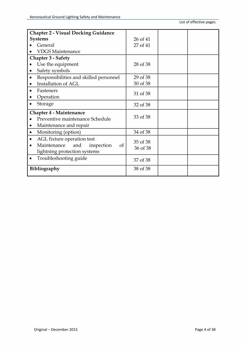
Chapter 2 - Visual Docking Guidance Systems
General
VDGS Maintenance
26 of 41 27 of 41
Chapter 3 - Safety
Use the equipment
Safety symbols
28 of 38
Responsibilities and skilled personnel
Installation of AGL
29 of 38 30 of 38
Fasteners
Operation 31 of 38
Storage 32 of 38
Chapter 4 - Maintenance
Preventive maintenance Schedule
Maintenance and repair
33 of 38
Monitoring (option) 34 of 38
AGL fixture operation test
Maintenance and inspection of lightning protection systems
35 of 38 36 of 38
Troubleshooting guide 37 of 38
Bibliography 38 of 38

Aeronautical Ground Lighting Safety and Maintenance Table of approval
Original – December 2015 Page 5 of 38
Table of Approval
Name and position Date Signature
Prepared by: Minir Istrefi, Inspector, Aerodromes Department
04.12.2015
Authorised by: Burim Dinarama, Director, Aerodromes Department
08. 12.2015
Quality Check: Lendita Kika-Berisha, Manager, Quality and Safety Office
14. 12.2015
Approved by: Dritan Gjonbalaj, Director General
15. 12.2015
Aeronautical Ground Lighting Safety and Maintenance Distribution list / Review table
Original – December 2015 Page 6 of 38
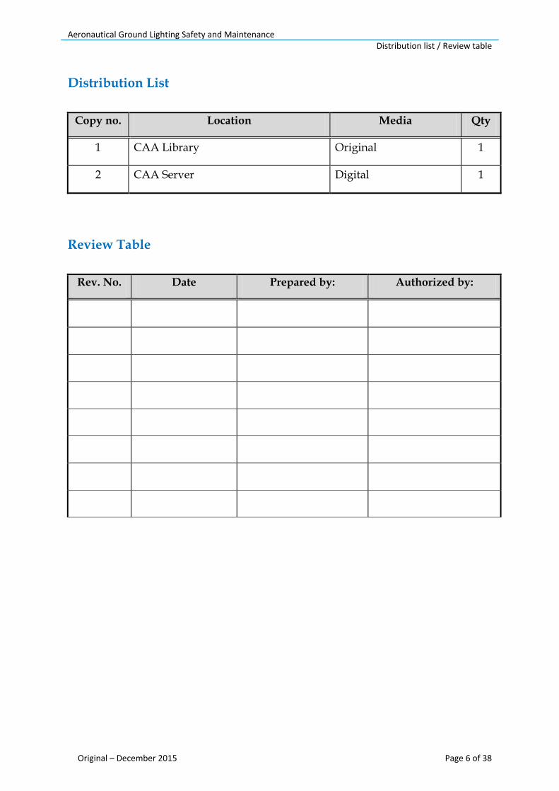
Distribution List
Copy no. Location Media Qty
1 CAA Library Original 1
2 CAA Server Digital 1
Review Table
Rev. No. Date Prepared by: Authorized by:
Aeronautical Ground Lighting Safety and Maintenance Table of content
Original – December 2015 Page 7 of 38
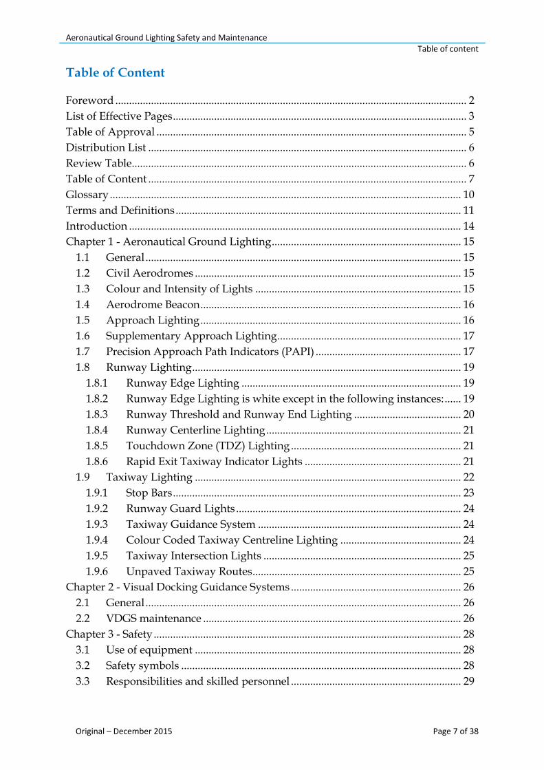
Table of Content
Foreword ................................................................................................................................ 2
List of Effective Pages ........................................................................................................... 3
Table of Approval ................................................................................................................. 5
Distribution List .................................................................................................................... 6
Review Table.......................................................................................................................... 6
Table of Content .................................................................................................................... 7
Glossary ................................................................................................................................ 10
Terms and Definitions ........................................................................................................ 11
Introduction ......................................................................................................................... 14
Chapter 1 - Aeronautical Ground Lighting ..................................................................... 15
1.1 General ................................................................................................................... 15
1.2 Civil Aerodromes ................................................................................................. 15
1.3 Colour and Intensity of Lights ........................................................................... 15
1.4 Aerodrome Beacon ............................................................................................... 16
1.5 Approach Lighting ............................................................................................... 16
1.6 Supplementary Approach Lighting ................................................................... 17
1.7 Precision Approach Path Indicators (PAPI) ..................................................... 17
1.8 Runway Lighting .................................................................................................. 19
1.8.1 Runway Edge Lighting ................................................................................ 19
1.8.2 Runway Edge Lighting is white except in the following instances: ...... 19
1.8.3 Runway Threshold and Runway End Lighting ....................................... 20
1.8.4 Runway Centerline Lighting ....................................................................... 21
1.8.5 Touchdown Zone (TDZ) Lighting .............................................................. 21
1.8.6 Rapid Exit Taxiway Indicator Lights ......................................................... 21
1.9 Taxiway Lighting ................................................................................................. 22
1.9.1 Stop Bars ......................................................................................................... 23
1.9.2 Runway Guard Lights .................................................................................. 24
1.9.3 Taxiway Guidance System .......................................................................... 24
1.9.4 Colour Coded Taxiway Centreline Lighting ............................................ 24
1.9.5 Taxiway Intersection Lights ........................................................................ 25
1.9.6 Unpaved Taxiway Routes ............................................................................ 25
Chapter 2 - Visual Docking Guidance Systems .............................................................. 26
2.1 General ................................................................................................................... 26
2.2 VDGS maintenance .............................................................................................. 26
Chapter 3 - Safety ................................................................................................................ 28
3.1 Use of equipment ................................................................................................. 28
3.2 Safety symbols ...................................................................................................... 28
3.3 Responsibilities and skilled personnel .............................................................. 29
Aeronautical Ground Lighting Safety and Maintenance Table of content
Original – December 2015 Page 8 of 38
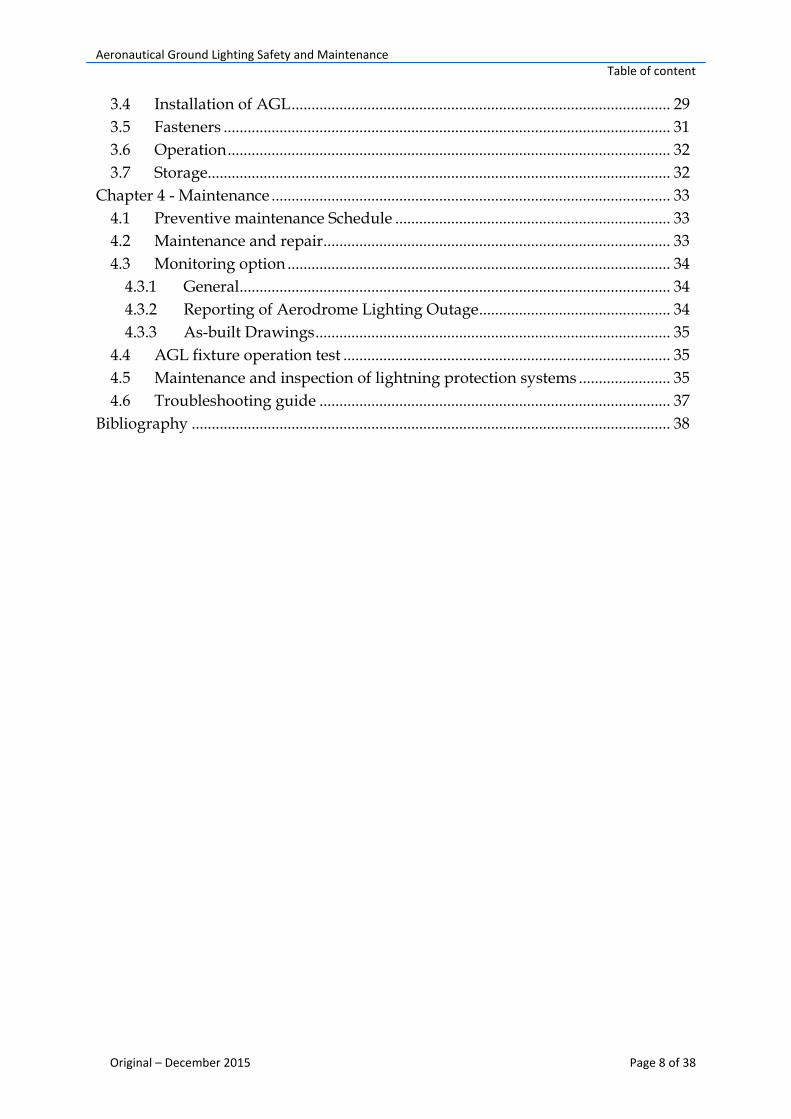
3.4 Installation of AGL ............................................................................................... 29
3.5 Fasteners ................................................................................................................ 31
3.6 Operation ............................................................................................................... 32
3.7 Storage.................................................................................................................... 32
Chapter 4 - Maintenance .................................................................................................... 33
4.1 Preventive maintenance Schedule ..................................................................... 33
4.2 Maintenance and repair ....................................................................................... 33
4.3 Monitoring option ................................................................................................ 34
4.3.1 General ............................................................................................................ 34
4.3.2 Reporting of Aerodrome Lighting Outage ................................................ 34
4.3.3 As-built Drawings ......................................................................................... 35
4.4 AGL fixture operation test .................................................................................. 35
4.5 Maintenance and inspection of lightning protection systems ....................... 35
4.6 Troubleshooting guide ........................................................................................ 37
Bibliography ........................................................................................................................ 38
Aeronautical Ground Lighting Safety and Maintenance
Original – December 2015 Page 9 of 38
INTENTIONALLY LEFT BLANK
Aeronautical Ground Lighting Safety and Maintenance Glossary
Original – December 2015 Page 10 of 38
Glossary
AGL Aeronautical Ground Lighting
AVDGS Advanced Visual Docking Guidance Systems
CAA Civil Aviation Authority
CCR Constant Current Regulator
CU Concentrator Unit
FOD Foreign Object Debris
ICAO International Civil Aviation Organization
ILS Instrument Landing System
ISO International Standardization Organization
LVP Low Visibility Procedures
IEC International Electro technical Committee
LED Light Emitting Diode
LMS Light Monitor and Switch unit
MEHT Minimum Eye Height over Threshold
MOR Mandatory Occurrence Report
PAPI Precision Approach Path Indicators
SMS Safety Management System
SOP Standard Operating Procedure

Aeronautical Ground Lighting Safety and Maintenance Terms and definitions
Original – December 2015 Page 11 of 38
Terms and Definitions
In this manual, the terms are conform to those in Law No. 03/L-051 on Civil Aviation, Regulation 1/2008 on Aerodromes as amended and supplemented with Regulation No. 04/2012, and Annex 14 Volume I, to the Convention on International Civil Aviation. For the purpose of aeronautical ground lighting, safety and maintenance, the following definitions apply:
Term Definition
Aerodrome Aerodrome means a defined area on land or water (including any buildings, installations and equipment) intended or designed to be used either wholly or partly for the arrival, departure and surface movement of aircraft.
Aerodrome Operator Any person or legal entity authorized by the Authority to manage and operate an aerodrome by means of issuance of an aerodrome certificate.
Aeronautical Ground Lighting
Aeronautical Ground Lighting service includes
(a) approach lighting;
(b) Supplementary Approach Lighting;
(c) Precision Approach Path Indicator (PAPI);
(d) Runway Lighting;
(e) Taxiway Lighting
(f) Aerodrome Beacon.
ILCMS Systems (ILCMS) that check the status of the light by performing continuity test on the secondary of the ILCMS remote module. The monitoring option does a check on the light. In case of a failure of the light, the failure is detected by the electronics embedded in the light.
Authority In this manual, the Authority means the Civil Aviation Authority of the Republic of Kosovo.
Runway Edge Lighting Runway Edge Lighting is located along the edges of the area declared for use as the runway delineated by white edge markings, and may be provided either
Aeronautical Ground Lighting Safety and Maintenance Terms and definitions
Original – December 2015 Page 12 of 38
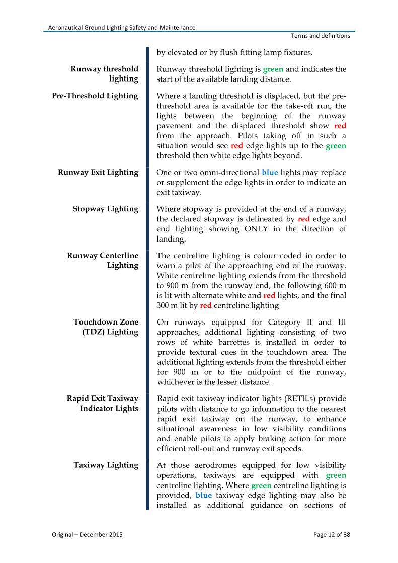
by elevated or by flush fitting lamp fixtures.
Runway threshold lighting
Runway threshold lighting is green and indicates the start of the available landing distance.
Pre-Threshold Lighting Where a landing threshold is displaced, but the pre-threshold area is available for the take-off run, the lights between the beginning of the runway pavement and the displaced threshold show red from the approach. Pilots taking off in such a situation would see red edge lights up to the green
threshold then white edge lights beyond.
Runway Exit Lighting One or two omni-directional blue lights may replace or supplement the edge lights in order to indicate an exit taxiway.
Stopway Lighting Where stopway is provided at the end of a runway, the declared stopway is delineated by red edge and end lighting showing ONLY in the direction of landing.
Runway Centerline Lighting
The centreline lighting is colour coded in order to warn a pilot of the approaching end of the runway. White centreline lighting extends from the threshold to 900 m from the runway end, the following 600 m is lit with alternate white and red lights, and the final 300 m lit by red centreline lighting
Touchdown Zone (TDZ) Lighting
On runways equipped for Category II and III approaches, additional lighting consisting of two rows of white barrettes is installed in order to provide textural cues in the touchdown area. The additional lighting extends from the threshold either for 900 m or to the midpoint of the runway, whichever is the lesser distance.
Rapid Exit Taxiway Indicator Lights
Rapid exit taxiway indicator lights (RETILs) provide pilots with distance to go information to the nearest rapid exit taxiway on the runway, to enhance situational awareness in low visibility conditions and enable pilots to apply braking action for more efficient roll-out and runway exit speeds.
Taxiway Lighting At those aerodromes equipped for low visibility operations, taxiways are equipped with green centreline lighting. Where green centreline lighting is provided, blue taxiway edge lighting may also be installed as additional guidance on sections of
Aeronautical Ground Lighting Safety and Maintenance Terms and definitions
Original – December 2015 Page 13 of 38
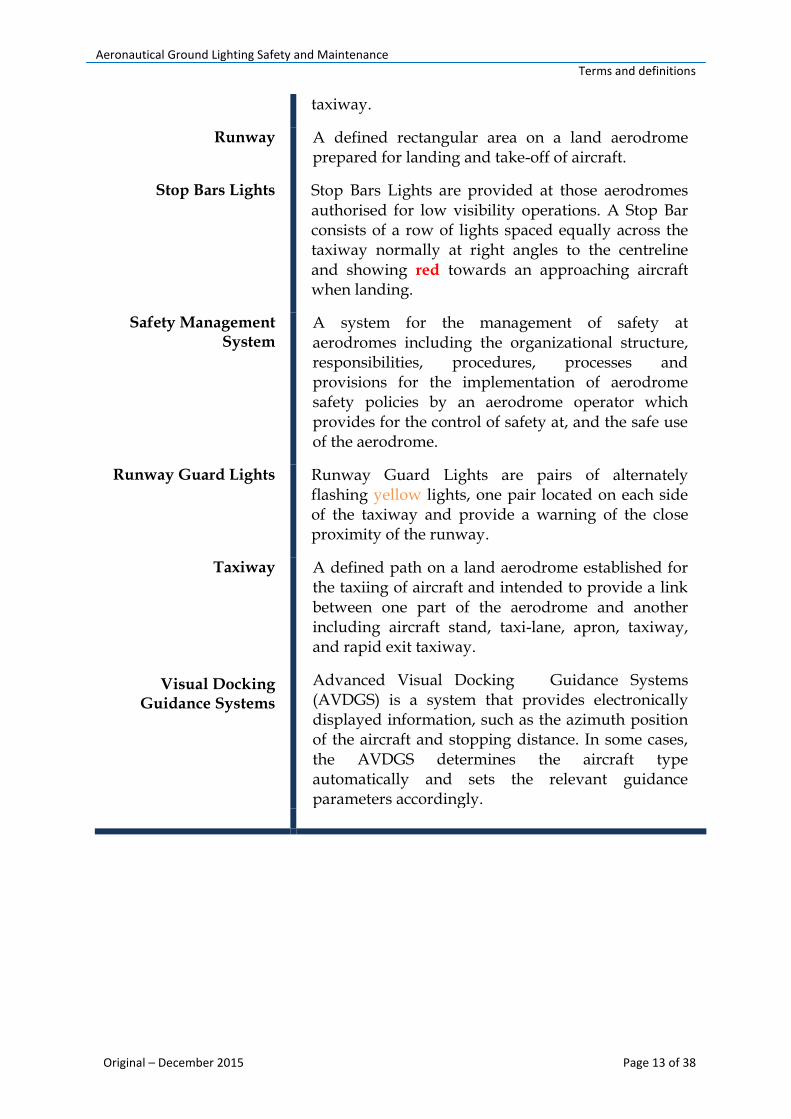
taxiway.
Runway A defined rectangular area on a land aerodrome prepared for landing and take-off of aircraft.
Stop Bars Lights Stop Bars Lights are provided at those aerodromes authorised for low visibility operations. A Stop Bar consists of a row of lights spaced equally across the taxiway normally at right angles to the centreline and showing red towards an approaching aircraft when landing.
Safety Management System
A system for the management of safety at aerodromes including the organizational structure, responsibilities, procedures, processes and provisions for the implementation of aerodrome safety policies by an aerodrome operator which provides for the control of safety at, and the safe use of the aerodrome.
Runway Guard Lights Runway Guard Lights are pairs of alternately flashing yellow lights, one pair located on each side of the taxiway and provide a warning of the close proximity of the runway.
Taxiway
Visual Docking
Guidance Systems
A defined path on a land aerodrome established for the taxiing of aircraft and intended to provide a link between one part of the aerodrome and another including aircraft stand, taxi-lane, apron, taxiway, and rapid exit taxiway.
Advanced Visual Docking Guidance Systems (AVDGS) is a system that provides electronically displayed information, such as the azimuth position of the aircraft and stopping distance. In some cases, the AVDGS determines the aircraft type automatically and sets the relevant guidance parameters accordingly.

Aeronautical Ground Lighting Safety and Maintenance Introduction
Original – December 2015 Page 14 of 38
Introduction
The service ability and operational reliability of air navigation equipment and installations are requirement, for the safe operation of aircraft in the airport area. Apart from visual aids, the air navigation equipment and installations include electronic landing aids, navigation equipment, radar and equipment of the meteorological services. Guidance on the maintenance of visual aids is given in Chapter 5 of the manual. Maintenance programs for other equipment and installations are to be established by the appropriate authorities (ATC, Meteorological Services).
The required service ability of installations and equipment will only be achieved as long as a constant power supply is maintained. To this end, regular maintenance work is required for airport equipment and installations Aeronautical Ground Lighting, distributing primary power and equipment supplying the secondary power when there is a circuit breakdown. The following paragraphs contain guidance on establishing maintenance programs for Aeronautical Ground Lighting and the individual elements of the power supply systems.
Aeronautical Ground Lighting Safety and Maintenance Chapter 1 – Aeronautical ground lighting
Original – December 2015 Page 15 of 38
Chapter 1 - Aeronautical Ground Lighting 1.1 General Aeronautical Ground Lighting (AGL) is the generic term used to describe the various lighting systems that are provided on an aerodrome for the guidance of pilots operating aircraft both at night and in low visibility conditions. AGL systems vary in complexity from the basic patterns found at small aerodromes in support of flying training operations, to the more advanced systems used in support of "all-weather operations", usually associated with an Instrument Landing System (ILS).
The following paragraphs outline the AGL systems that have been accepted by the CAA as meeting both of the Republic of Kosovo aerodrome certification criteria and internationally agreed standards and recommended practices. 1.2 Civil Aerodromes
Details of AGL are notified in the AIP and on the appropriate Instrument Approach Charts. Where the AGL provided at a certified aerodrome does not conform to the applicable specification in Regulation 1/2008 on Aerodromes as amended and supplemented with Regulation No. 04/2012, and Annex 14 Volume I, to the Convention on International Civil Aviation, an appropriate aerodrome entry is included in the AIP or, if the deficiency is of a temporary nature, a Notice to Airmen (NOTAM) is issued detailing the AGL that is available. 1.3 Colour and Intensity of Lights
1.3.1 High intensity AGL systems that are provided in support of low visibility operations normally have facility to independently control the luminance intensity of each element of the system. The intensities are set up, usually by the air navigation service provider, to suit local conditions. A pilot may ask for the intensity of an element(s) of the system to be adjusted if found to be inappropriate for the flight operation. 1.3.2 The performance specification of high intensity lighting is defined by the need to provide guidance by day in low visibility conditions; the highest intensity settings are normally used in these conditions. Lower intensities are normally used by night. 1.3.3 Low intensity systems are provided at those aerodromes at which operations are conducted at night but not in low visibility conditions; the luminance intensity of these systems is not normally adjustable.

Aeronautical Ground Lighting Safety and Maintenance Chapter 1 – Aeronautical ground lighting
Original – December 2015 Page 16 of 38
1.4 Aerodrome Beacon 1.4.1 An Aerodrome Beacon would normally be provided at those aerodromes that operate at night and where the level of background lighting, the surrounding terrain, the proximity of other aerodromes or the lack of navigation aids would make the aerodrome difficult to locate or to identify. 1.4.2 An Identification Beacon flashing a two letter identification code in green would normally be provided at an aerodrome where a number of aerodromes in the same vicinity operate at night and confusion could arise as to identity.
1.4.3 A Location Beacon would normally be provided at an aerodrome that is situated well away from other aerodromes and where no confusion could exist as to identity. The signal produced by a Location Beacon is determined by the amount of background lighting as follows:
a) Where the aerodrome is also situated well away from areas of high background lighting, the Location Beacon would display a white flashing light.
b) Where the aerodrome is situated in an area where there is a high level of background lighting, such as in the vicinity of a city where a flashing a white light would be difficult to see, the Location Beacon would display a green light flashing alternately with a white light.
1.5 Approach Lighting
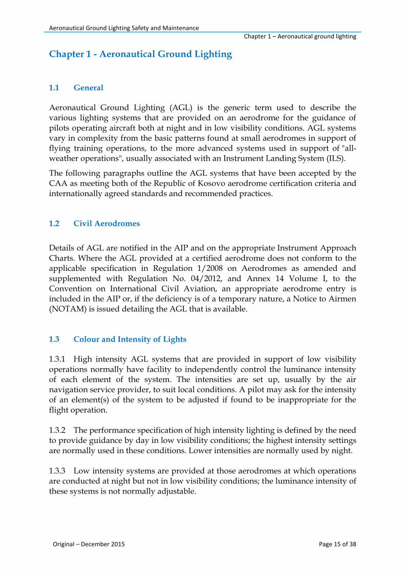
1.5.1 A variety of approach lighting systems, based on the centre line and cross bar concept, based on the requirements of ICAO Annex 14 volume I, may be used at aerodromes in the Republic of Kosovo. These systems range from the simple low intensity centre line and cross bar - shown at Figure 1.1 - intended to serve visual runways at night only, to the more complex Calvert System comprising centerline and 5 cross bars - shown at Figure 1.3 and 1.4 - for day and night use on ILS equipped runways.
1.5.2 A simple approach lighting system consist of a row of lights on the extended centre line of the runway extending, whenever possible, over a distance of not less than 420 m from the threshold with a row of lights forming crossbar 18 m or 30 m in length at a distance of 300 m from the threshold.
Aeronautical Ground Lighting Safety and Maintenance Chapter 1 – Aeronautical ground lighting
Original – December 2015 Page 17 of 38
Figure 1.1 Figure 1.2 Figure 1.3
1.6 Supplementary Approach Lighting
At those aerodromes where Category II and III approaches are conducted, Supplementary Approach Lighting consisting of white centerline barrettes and two rows of red side barrettes, as shown at Figure 1.3, is installed in order to provide the pilot with enhanced visual cues over the last 300 m of the approach. NOTE: At aerodromes with displaced thresholds, the supplementary approach lighting may be inset into the runway and in certain weather and ambient light conditions the centerline barrettes, at the higher intensity settings, can partially obscure the runway centerline lighting to pilots lining up for departure. Pilots experiencing problems of this nature should ask for the intensity of the supplementary lighting to be adjusted or extinguished.
1.7 Precision Approach Path Indicators (PAPI)
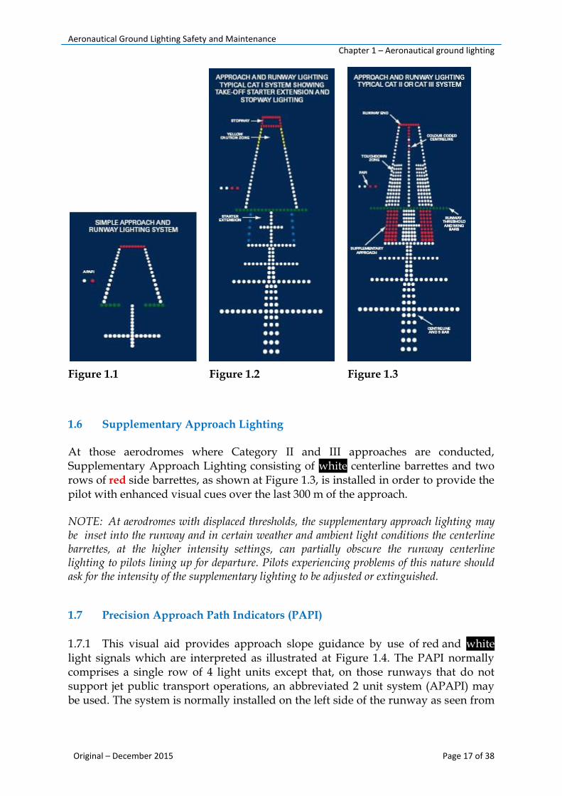
1.7.1 This visual aid provides approach slope guidance by use of red and white light signals which are interpreted as illustrated at Figure 1.4. The PAPI normally comprises a single row of 4 light units except that, on those runways that do not support jet public transport operations, an abbreviated 2 unit system (APAPI) may be used. The system is normally installed on the left side of the runway as seen from
Aeronautical Ground Lighting Safety and Maintenance Chapter 1 – Aeronautical ground lighting
Original – December 2015 Page 18 of 38
the approach. However, the units can be located on the right side if it is impracticable to install on the left.
1.7.2 The PAPI signal is not designed to be used beyond 15° either side of the runway centerline. Any additional restrictions placed on the use of a particular installation will be notified under the 'Warnings' section of the appropriate aerodrome entry in the AIP. NOTE: Where obstacles located at the extremities of the visual signal preclude the provision of safe clearance, the appropriate aerodrome entry in the AIP will be annotated to that effect.
Figure 1.4 Typical PAPI Systems
1.7.3 Where used together with ILS, PAPI is located so as to ensure, as far as is practicable, correlation between the two approach paths. However, such a siting is made on the assumption that the pilot's eye level is above the ILS glide path receiver aerial, as is the case with most commercial aircraft. Pilots of aircraft in which the ILS aerial is mounted above the level of the pilot's eye may see a PAPI indication 'slightly low' (see Figure 1.4 D) when on the ILS glide path.

Aeronautical Ground Lighting Safety and Maintenance Chapter 1 – Aeronautical ground lighting
Original – December 2015 Page 19 of 38
1.8 Runway Lighting
All runways certified for night use have Edge, Threshold and End Lighting. Centerline and Touchdown Zone Lighting is provided as additional guidance in support of low visibility operations. 1.8.1 Runway Edge Lighting Runway Edge Lighting is located along the edges of the area declared for use as the runway delineated by white edge markings, and may be provided either by elevated or by flush fitting lamp fixtures. At aerodromes where elevated runway edge lights are employed, the light fixtures may be located on the grass shoulder just beyond the declared runway width. Portable battery operated lights may be used in place of fixed lamp fittings at small aerodromes where limited operations take place at night. Runway Edge Lighting is white except in the following instances: a) Caution Zone Lighting
On ILS equipped runways without centerline lighting, yellow edge lighting as illustrated at Figure 1.2, is installed on the upwind 600 m or one third of the lighted runway length available, whichever is the less. The yellow 'caution zone' so formed gives a visual warning of the approaching runway end. b) Pre-Threshold Lighting
Where a landing threshold is displaced, but the pre-threshold area is available for the take-off run, the lights between the beginning of the runway pavement and the displaced threshold show red from the approach, as illustrated at Figure 1.5. Pilots taking off in such a situation would see red edge lights up to the green threshold then white edge lights beyond. Where a starter extension, narrower than its associated runway is provided, blue edge lighting is normally used to mark the edges, as illustrated at Figure 1.5.
c) Runway Exit Lighting
One or two omni-directional blue lights may replace or supplement the edge lights in order to indicate an exit taxiway. d) Stopway Lighting
Where stopway is provided at the end of a runway, the declared stopway is delineated by red edge and end lighting as illustrated in Figure 1.5 showing ONLY in the direction of landing. A stopway is provided for emergency use only and is not normally suitable for routine use.

Aeronautical Ground Lighting Safety and Maintenance Chapter 1 – Aeronautical ground lighting
Original – December 2015 Page 20 of 38
Figure 1.5 Typical Runway Threshold and Runway End Lights High Intensity for Precision Approach Runways
1.8.2 Runway Threshold and Runway End Lighting
Runway threshold lighting is green and indicates the start of the available landing distance. Green threshold wing-bars are provided at certain aerodromes where there is a need to accentuate the threshold. Patterns vary from the full threshold and wing- bar lighting shown at Figures 1.2, 1.3, and 1.5 to abbreviated versions shown at Figures 1.1 and 1.5. Runway end lighting is red and marks the extremity of the runway that is available for manoeuvring. Pilots should not land before the green threshold lighting nor continue a landing roll or taxi beyond the red runway end lights.
Unidirectional elevated
lights - green
Unidirectional inset lights at
equal intervals of not more
than 3m - green
TYPICAL RUNWAY THRESHOLD
LIGHTS (HIGH INTENSITY) FOR
PRECISION APPROACH RUNWAYS
TYPICAL RUNWAY THRESHOLD LIGHTS
WITH THRESHOLD WING BARS (HIGH
INTENSITY) FOR PRECISION APPROACH
RUNWAYS
Threshold wing bar.
Unidirectional elevated
lights - green
TYPICAL RUNWAY END LIGHTS (HIGH
INTENSITY) FOR PRECISION
APPROACH RUNWAYS
Six unidirectional inset lights at
equal intervals - red

Aeronautical Ground Lighting Safety and Maintenance Chapter 1 – Aeronautical ground lighting
Original – December 2015 Page 21 of 38
1.8.3 Runway Centerline Lighting
High intensity centreline lighting is provided in addition to edge lighting on runways equipped for low visibility operations. The centreline lighting is colour coded in order to warn a pilot of the approaching end of the runway. White centreline lighting extends from the threshold to 900 m from the runway end, the following 600 m is lit with alternate white and red lights, and the final 300 m lit by red centreline lighting, as shown at Figure 1.3. 1.8.4 Touchdown Zone (TDZ) Lighting
On runways equipped for Category II and III approaches, additional lighting consisting of two rows of white barrettes, as shown at Figure 1.3, is installed in order to provide textural cues in the touchdown area. The additional lighting extends from the threshold either for 900 m or to the midpoint of the runway, whichever is the lesser distance.
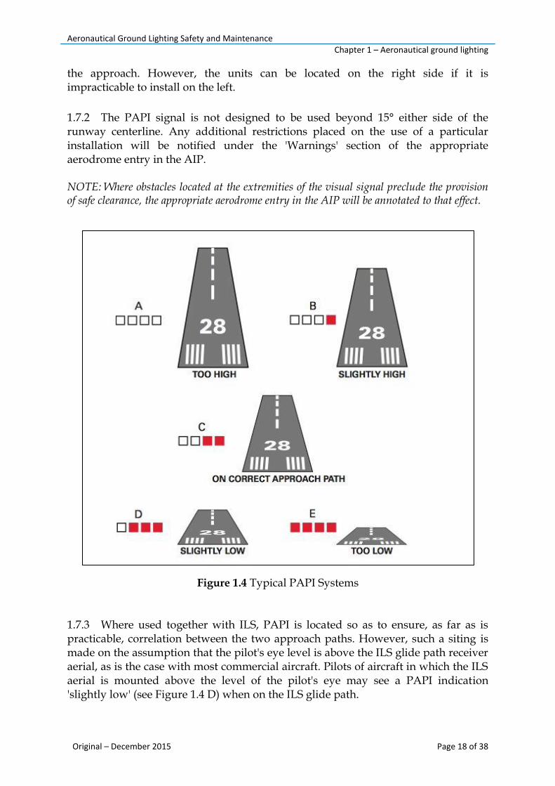
NOTE: The length of the TDZ lighting (normally 900 m) determines the length of the Obstacle Free Zone (OFZ) established to protect CAT II and III approaches below decision height (DH) and in the event of a baulked landing (or go- around) after DH. A go-around initiated beyond the end of the TDZ lighting is unlikely to be contained within the OFZ. 1.8.5 Rapid Exit Taxiway Indicator Lights 1.8.5.1 Rapid exit taxiway indicator lights (RETILs) provide pilots with distance to go information to the nearest rapid exit taxiway on the runway, to enhance situational awareness in low visibility conditions and enable pilots to apply braking action for more efficient roll-out and runway exit speeds.
1.8.5.2 RETILs consist of six yellow lights adjacent to the runway centreline and configured in a three/two/one pattern spaced 100 m apart; the single light is 100 m from the start of the turn for the rapid exit taxiway, see Figure 1.6.
Aeronautical Ground Lighting Safety and Maintenance Chapter 1 – Aeronautical ground lighting
Original – December 2015 Page 22 of 38
Figure 1.6 Rapid Exit Taxiway Indicator Lights
1.9 Taxiway Lighting
At those aerodromes equipped for low visibility operations, taxiways are equipped with green centreline lighting, otherwise blue edge lighting is provided, as shown in Figure 1.7. Where green centreline lighting is provided, blue taxiway edge lighting may also be installed as additional guidance on sections of taxiway that are difficult to negotiate. Green taxiway centreline lighting may be provided on the runway prior to an exit taxiway in order to give lead-off guidance. However, see paragraph 9.5. The edge of aprons, turning and holding areas are normally marked by blue lighting.
NOTE 1: Where centreline lighting is installed on a taxiway leading onto a runway, the taxiway lighting is curved onto the near side of the runway centreline and pilots should make an appropriate allowance for any loss of Runway Declared Distance incurred in following the 'lead-on' lighting whilst lining up for take-off.
NOTE 2: Taxiway centrelines are intended to provide safe clearance between the largest aircraft that the taxiway is designed to accommodate and fixed objects such as buildings, aircraft stands etc, provided that the pilot of the taxiing aircraft keeps the 'Cockpit' of the aircraft on the centreline and that aircraft on stands are properly parked. Taxi Holding Positions are normally located so as to ensure clearance between an aircraft holding and any aircraft passing in front of the holding aircraft, provided that the holding aircraft is properly positioned behind the holding position. Clearance to the rear of any holding aircraft cannot be guaranteed. When following a taxiway route, pilots and persons towing aircraft are expected to keep a good lookout, consistent with the prevailing visibility and are responsible for taking all possible measures to avoid a collision with another aircraft or a vehicle.

Aeronautical Ground Lighting Safety and Maintenance Chapter 1 – Aeronautical ground lighting
Original – December 2015 Page 23 of 38
Figure 1.7 Taxiway Lighting
1.9.1 Stop Bars Lighted Stop Bars are provided at those aerodromes authorised for low visibility operations. A Stop Bar consists of a row of lights spaced equally across the taxiway normally at right angles to the centreline and showing red towards an approaching aircraft when lit. Stop Bars are normally installed in association with green Lead-on Lights which form part of the taxiway centreline lighting beyond the Stop Bar. NOTE: At aerodromes where, for example, a Stop Bar is located on or close to a bend in the taxiway route, additional elevated red lights may be installed outboard of each taxiway edge as shown at Figure 1.7, in order to provide maximum advanced warning of the Stop Bar location.
Figure 1.8 Stop Bar
Aeronautical Ground Lighting Safety and Maintenance Chapter 1 – Aeronautical ground lighting
Original – December 2015 Page 24 of 38
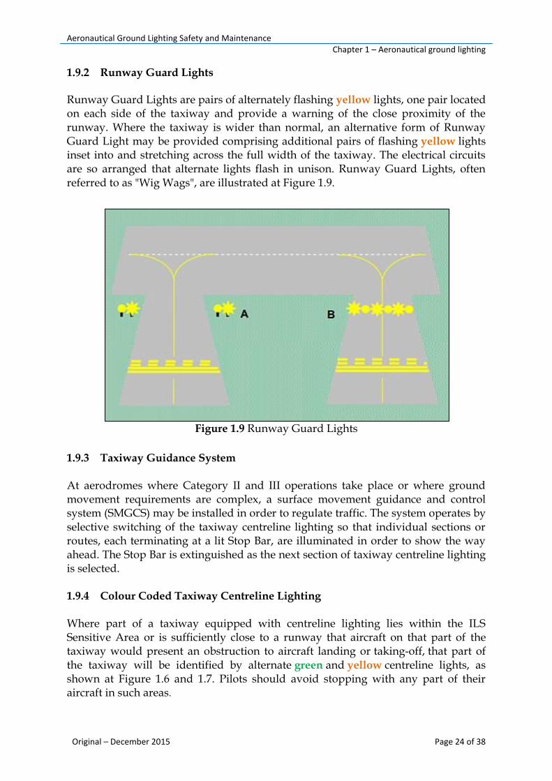
1.9.2 Runway Guard Lights Runway Guard Lights are pairs of alternately flashing yellow lights, one pair located on each side of the taxiway and provide a warning of the close proximity of the runway. Where the taxiway is wider than normal, an alternative form of Runway Guard Light may be provided comprising additional pairs of flashing yellow lights inset into and stretching across the full width of the taxiway. The electrical circuits are so arranged that alternate lights flash in unison. Runway Guard Lights, often referred to as "Wig Wags", are illustrated at Figure 1.9.
Figure 1.9 Runway Guard Lights
1.9.3 Taxiway Guidance System
At aerodromes where Category II and III operations take place or where ground movement requirements are complex, a surface movement guidance and control system (SMGCS) may be installed in order to regulate traffic. The system operates by selective switching of the taxiway centreline lighting so that individual sections or routes, each terminating at a lit Stop Bar, are illuminated in order to show the way ahead. The Stop Bar is extinguished as the next section of taxiway centreline lighting is selected. 1.9.4 Colour Coded Taxiway Centreline Lighting Where part of a taxiway equipped with centreline lighting lies within the ILS Sensitive Area or is sufficiently close to a runway that aircraft on that part of the taxiway would present an obstruction to aircraft landing or taking-off, that part of the taxiway will be identified by alternate green and yellow centreline lights, as shown at Figure 1.6 and 1.7. Pilots should avoid stopping with any part of their aircraft in such areas.
Aeronautical Ground Lighting Safety and Maintenance Chapter 1 – Aeronautical ground lighting
Original – December 2015 Page 25 of 38
1.9.5 Taxiway Intersection Lights
At some aerodromes where multiple intersecting taxiways are not provided with selective route guidance, Taxiway Intersection Lights may be provided. These consist of a row of at least 3 steady yellow lights disposed symmetrically about the taxiway centreline. Pilots approaching an intersection where these lights are displayed should give way to crossing traffic unless otherwise instructed by air traffic control (ATC). 1.9.6 Unpaved Taxiway Routes
Where taxiing is confined to specific routes on unpaved areas, the routes may either be edged with blue portable lights laid out as for normal taxiway edge lighting, or be provided with reflective taxiway edge markers. In certain circumstances, apron floodlighting may be accepted as sufficient illumination of adjacent taxiways. On grass aerodromes where specific taxiways are not provided, portable white lights may be used to mark the boundary of the manoeuvring area.
Aeronautical Ground Lighting Safety and Maintenance Chapter 2 – Visual guidance docking system
Original – December 2015 Page 26 of 38
Chapter 2 - Visual Docking Guidance Systems 2.1 General
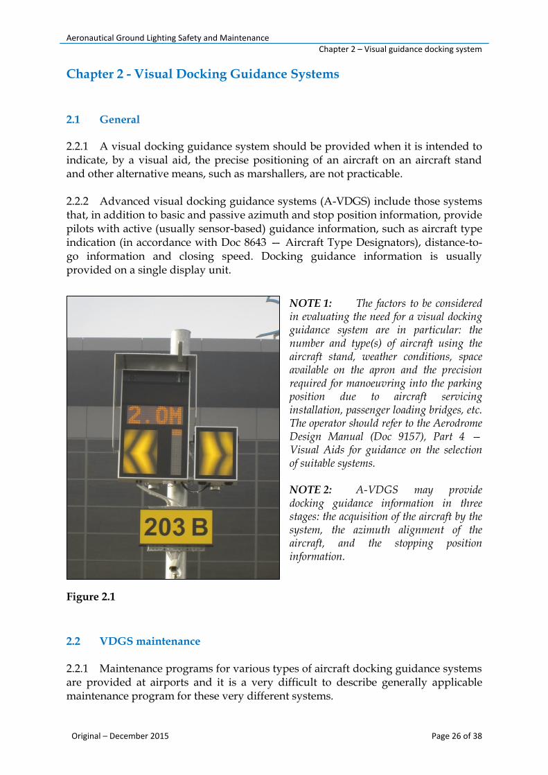
2.2.1 A visual docking guidance system should be provided when it is intended to indicate, by a visual aid, the precise positioning of an aircraft on an aircraft stand and other alternative means, such as marshallers, are not practicable. 2.2.2 Advanced visual docking guidance systems (A-VDGS) include those systems that, in addition to basic and passive azimuth and stop position information, provide pilots with active (usually sensor-based) guidance information, such as aircraft type indication (in accordance with Doc 8643 — Aircraft Type Designators), distance-to-go information and closing speed. Docking guidance information is usually provided on a single display unit.
NOTE 1: The factors to be considered in evaluating the need for a visual docking guidance system are in particular: the number and type(s) of aircraft using the aircraft stand, weather conditions, space available on the apron and the precision required for manoeuvring into the parking position due to aircraft servicing installation, passenger loading bridges, etc. The operator should refer to the Aerodrome Design Manual (Doc 9157), Part 4 — Visual Aids for guidance on the selection of suitable systems. NOTE 2: A-VDGS may provide docking guidance information in three stages: the acquisition of the aircraft by the system, the azimuth alignment of the aircraft, and the stopping position information.
Figure 2.1
2.2 VDGS maintenance 2.2.1 Maintenance programs for various types of aircraft docking guidance systems are provided at airports and it is a very difficult to describe generally applicable maintenance program for these very different systems.
Aeronautical Ground Lighting Safety and Maintenance Chapter 2 – Visual guidance docking system
Original – December 2015 Page 27 of 38
Principal requirements to be checked and maintenance action to be taken, if necessary, include: Daily:
- system for over-all operation; - repairing lamps; - replacing burnt-out lamps.
Semi-annually:
- alignment of the system; - adjusting.
Annually:
- electrical connections (if provided) for corrosion, wear and tear; cleaning, tightening and replacing
- function of relays (if provided); cleaning or replacing - structure of the system and the function of all mechanical - parts; repairing - system for cleanness and moisture; cleaning and drying

Aeronautical Ground Lighting Safety and Maintenance Chapter 3 – Safety
Original – December 2015 Page 28 of 38
Chapter 3 - Safety 3.1 Use of equipment
To use the equipment safely, the responsible personnel should refer to the International Standard IEC 61820 “Electrical installation for lighting and beaconing of aerodromes - Constant current series circuits for aeronautical ground lighting - System design and installation requirements”, and to the International Standard IEC 61821 “Electrical installations for lighting and beaconing of aerodromes - Maintenance of aeronautical ground lighting circuits” for instructions on safety precautions.
3.2 Safety symbols
The safety symbols presented in this chapter will alert the responsible personnel to safety hazards and conditions that may result in personal injury, death, or property and equipment damage.
WARNING 1: Failure to observe this warning may result in personal injury, death, or equipment damage. WARNING 2: Risk of electrical shock. Disconnect equipment from line voltage. Failure to observe this
The responsible personnel should observe all safety regulations. To avoid injuries, power must always be removed prior to making any wire connections and touching any live part. Refer to the International Standards IEC 61820 and IEC 61821.
In addition for a parallel power supply, the responsible personnel should also take into account the International Standard IEC60598 (for class I equipment).
The responsible personnel should read and carefully follow the instructions given throughout user manual (manufactures instruction) before installing, operating, maintaining, or repairing the equipment.
The responsible personnel should follow all applicable safety procedures required by aerodrome operator, CAA, industry standards, and government or other regulatory agencies.
The responsible personnel should obtain and read Material Safety Data Sheets (MSDS) for all materials used.

Aeronautical Ground Lighting Safety and Maintenance Chapter 3 – Safety
Original – December 2015 Page 29 of 38
warning may result in personal injury, death, or equipment damage.
WARNING 3: Wear personal protective equipment. Failure to observe may result in serious injury. WARNING 4: Do not touch. Failure to observe this warning may result in personal injury, death, or equipment damage.
3.3 Responsibilities and skilled personnel
3.3.1 The term skilled personnel is defined here as individual who thoroughly understand the equipment and its safe operation, maintenance, and repair. Skilled personnel are physically capable of performing the required tasks, familiar with all relevant safety rules and regulations and have been trained to safely install, operate, maintain, and repair the equipment. It is the responsibility of the operator to ensure that its personnel meet these requirements.
3.3.2 The Accountable Manager has the overall responsibility for the provision of airport lighting facilities and associated stand-by power generating equipment.
3.3.3 The operator should appoint the responsible person who should be responsible for ensuring that appropriate maintenance and technical inspections of airport lighting facilities are carried out and recorded in accordance with the standards and the requirements.
3.3.4 The operator should appoint the Chief of AGL/PWR Unit who should be responsible for carrying out and recording the inspection and maintenance of all airport lighting systems.
3.3.5 AGL/PWR technicians are responsible for carrying out and recording the inspection and maintenance of on-airport emergency power generation facilities associated with airport lighting.
3.4 Installation of AGL
3.4.1 An AGL system should normally comprise a single control and monitoring equipment and several constant current series circuits. The following elements make up a typical constant current series circuit:
a) A constant current regulator (CCR.)

Aeronautical Ground Lighting Safety and Maintenance Chapter 3 – Safety
Original – December 2015 Page 30 of 38
b) A primary series circuit, which includes: i. Primary cable.
ii. AGL series transformer(s) or isolating transformer.
c) A secondary series circuit, which includes: i. Secondary cables.
ii. The light fitting or other devices.
Figure 3.1– Typical AGL Constant Current Series Circuit
3.4.2 The responsible personnel should read the installation section of all system component manuals before installing the equipment. A thorough understanding of system components and their requirements will help to install the equipment safely and efficiently.
3.4.3 Only skilled personnel should be engaged to install AGL equipment. Only approved equipment should be used. Using unapproved equipment in an approved system may void CAA approvals and will void the warranty.
3.4.4 AGL/PWR Unit personnel should ensure all equipment is rated and approved for the environment in which will be used. 3.4.5 AGL/PWR technician should ensure that all instructions for installing components and accessories are followed.
3.4.6 AGL/PWR technician should ensure to install all electrical connections based on applicable standards.
Aeronautical Ground Lighting Safety and Maintenance Chapter 3 – Safety
Original – December 2015 Page 31 of 38
3.4.7 Only electrical wire of sufficient gauge and insulation to handle the rated current and voltage demand should be used. All wiring must meet applicable standards.
3.4.8 Electrical wiring should be routed along a protected path. AGL/PWR technician should ensure they will not be damaged by moving equipment and animals (e.g. rodents).
3.4.9 AGL/PWR technician should protect components from damage, wear, and harsh environment conditions.
3.4.10 Ample room should be allowed for maintenance, panel accessibility (power products), and cover removal (power products). 3.4.11 Equipment should be protected with safety devices, as specified by applicable safety regulations. 3.4.12 If safety devices must be removed for installation, AGL/PWR technician should install them immediately after the work is completed and check them for proper functioning.
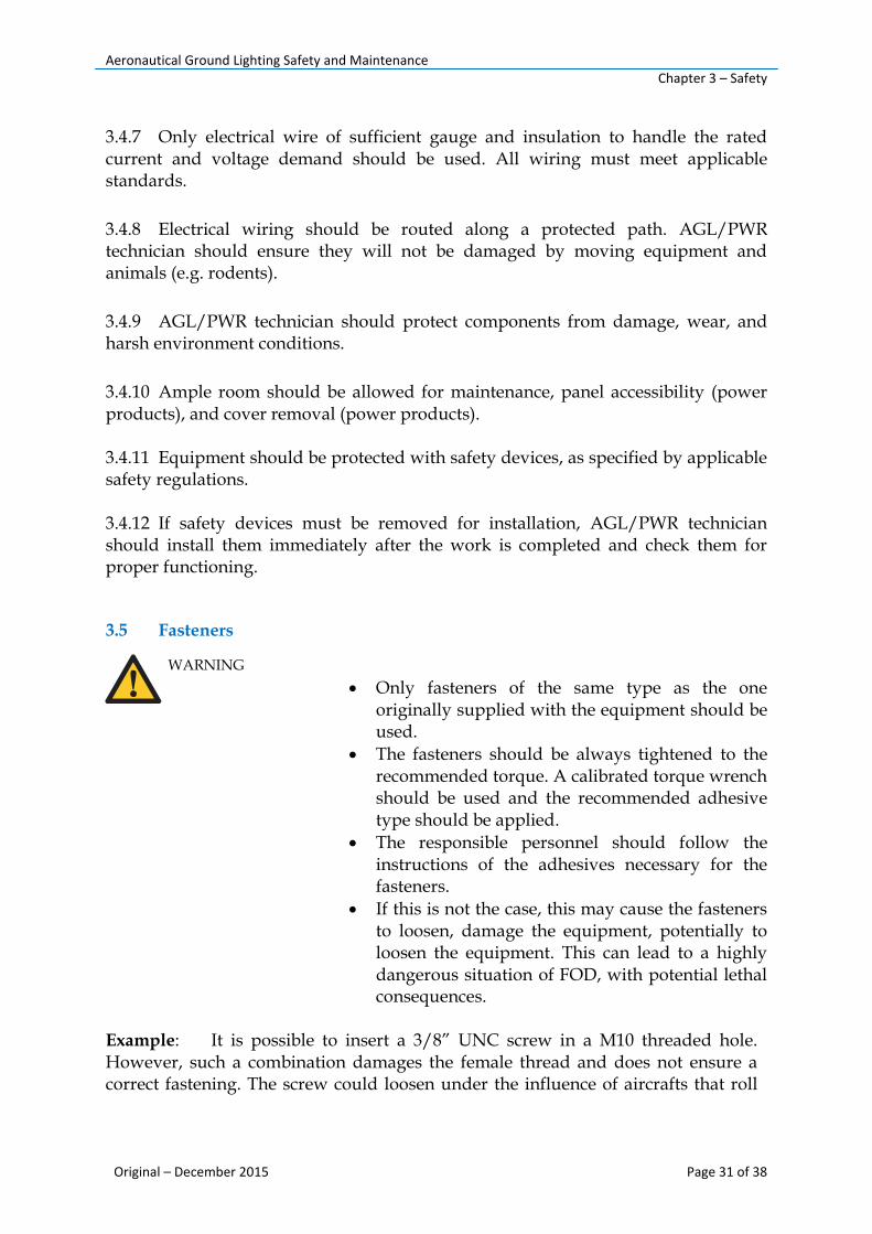
3.5 Fasteners
WARNING
Example: It is possible to insert a 3/8” UNC screw in a M10 threaded hole. However, such a combination damages the female thread and does not ensure a correct fastening. The screw could loosen under the influence of aircrafts that roll
Only fasteners of the same type as the one originally supplied with the equipment should be used.
The fasteners should be always tightened to the recommended torque. A calibrated torque wrench should be used and the recommended adhesive type should be applied.
The responsible personnel should follow the instructions of the adhesives necessary for the fasteners.
If this is not the case, this may cause the fasteners to loosen, damage the equipment, potentially to loosen the equipment. This can lead to a highly dangerous situation of FOD, with potential lethal consequences.

Aeronautical Ground Lighting Safety and Maintenance Chapter 3 – Safety
Original – December 2015 Page 32 of 38
over. The use of incorrect screws can lead to either damage to the thread in the mounting support or to an incorrect fixation of the equipment.
3.6 Operation Only skilled personnel, physically capable of operating the equipment and with no impairments in their judgment or reaction times, should operate AGL equipment. The responsible personnel should read all procedures before operating the equipment. A thorough understanding of system components and their operation will help to operate the equipment safely and efficiently. 3.6.1 Before starting the equipment, the AGL/PWR technician must check all safety interlocks and protective devices, such as panels and covers. All devices should be fully functional. If these devices are not working properly, the equipmen shoud not be operated. Automatic safety interlocks or locked-out electrical disconnects or pneumatic valves should not be deactivated or bypassed.
3.6.2 AGL/PWR personnel should never operate equipment with a known malfunction. 3.6.3 AGL/PWR personnel should not attempt to operate or service electrical equipment if standing water is present. 3.6.4 AGL/PWR personnel should not operate the equipment in humid, flammable, or explosive environments unless it has been rated for safe operation in these environments. 3.6.5 Exposed electrical connections on equipment while the power is ON should never be touched. The technician should make sure the exposed electrical connections are proven to be dead.
3.7 Storage The fixture should be stored in its original packing in a protected area.
Indoor storage:
For long storage periods (longer than one year), the LED lights should be energized once a year at nominal intensity (6.6Amps) for 20 minutes.
- Storage temperature: -10°C to +50°C. - Humidity: <95% non-condensing.
Aeronautical Ground Lighting Safety and Maintenance Maintenance
Original – December 2015 Page 33 of 38
Chapter 4 - Maintenance
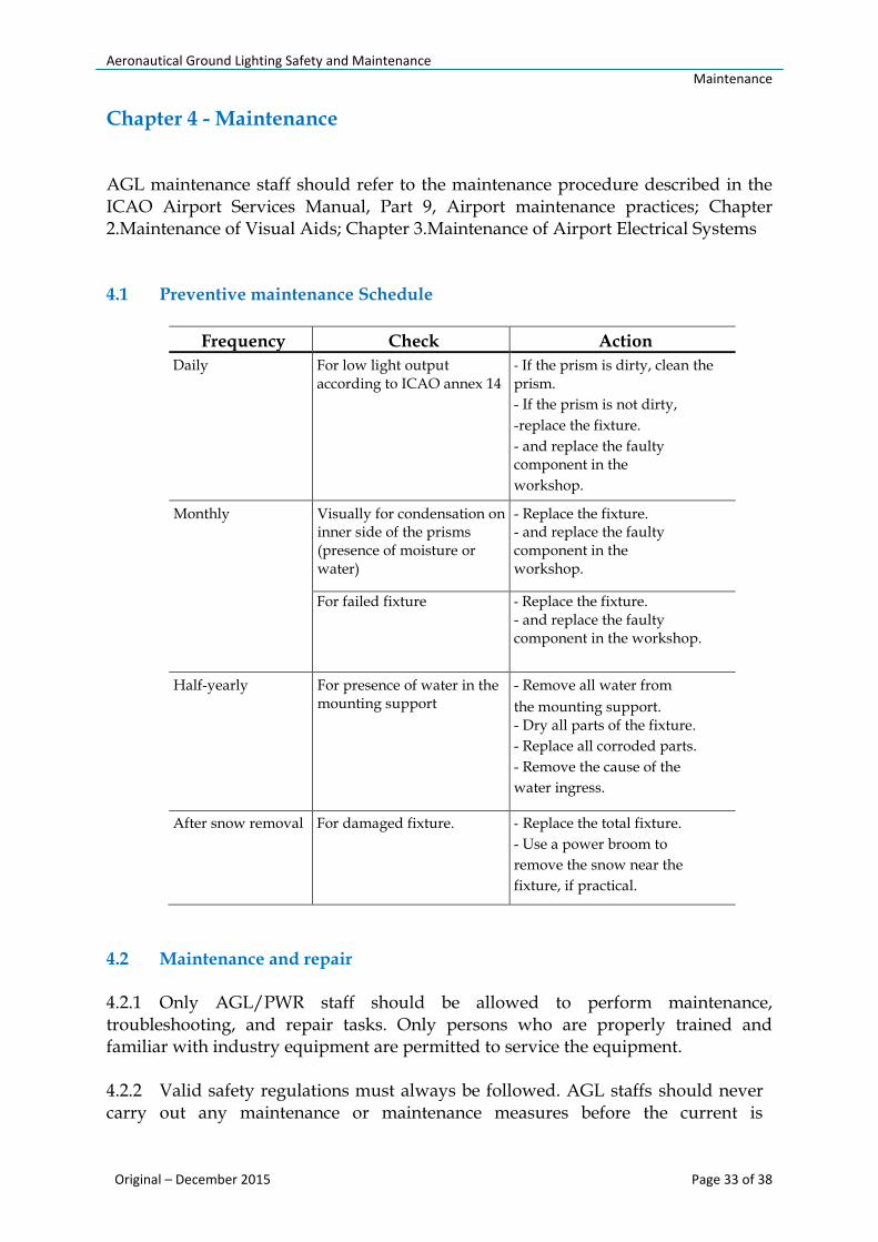
AGL maintenance staff should refer to the maintenance procedure described in the ICAO Airport Services Manual, Part 9, Airport maintenance practices; Chapter 2.Maintenance of Visual Aids; Chapter 3.Maintenance of Airport Electrical Systems 4.1 Preventive maintenance Schedule
Frequency Check Action
Daily For low light output according to ICAO annex 14
- If the prism is dirty, clean the prism.
- If the prism is not dirty,
-replace the fixture.
- and replace the faulty component in the
workshop.
Monthly Visually for condensation on inner side of the prisms (presence of moisture or water)
- Replace the fixture. - and replace the faulty component in the workshop.
For failed fixture - Replace the fixture. - and replace the faulty component in the workshop.
Half-yearly For presence of water in the mounting support
- Remove all water from
the mounting support. - Dry all parts of the fixture.
- Replace all corroded parts.
- Remove the cause of the
water ingress.
After snow removal For damaged fixture. - Replace the total fixture.
- Use a power broom to
remove the snow near the
fixture, if practical.
4.2 Maintenance and repair 4.2.1 Only AGL/PWR staff should be allowed to perform maintenance, troubleshooting, and repair tasks. Only persons who are properly trained and familiar with industry equipment are permitted to service the equipment. 4.2.2 Valid safety regulations must always be followed. AGL staffs should never carry out any maintenance or maintenance measures before the current is

Aeronautical Ground Lighting Safety and Maintenance Maintenance
Original – December 2015 Page 34 of 38
confirmed as safely disconnected. Extreme caution should be paid when disconnecting or connecting high voltage primary connectors.
4.2.3 The staff engaged in the maintenance of the electrical power supply systems, prior to the commencement of work, should ensure that all electrical services must be isolated from the supply and connected to earth. Full details of the work involved must be given to the authorized person responsible for the electrical engineering services at the airport with regard to the duration of the work and so on. It is recommended that prior to starting any cutting work the nature and location of services such as cable ducts and so on should be identified. Any installation or maintenance work should only be carried out by trained and experienced personnel 4.3 Monitoring option 4.3.1 General
The monitoring option should be available. AGL staff can use the monitoring option with the Lamp Fault Detection of Constant Current Regulators or with Individual Light Control and Monitoring Systems (ILCMS) that check the status of the light by performing a continuity test on the secondary of the ILCMS remote module. The monitoring option does a check on the light. In case of a failure of the light, the failure is detected by the electronics embedded in the light.
4.3.2 Reporting of Aerodrome Lighting Outage
Safety devices should always be used when working on the equipment.
Recommended maintenance procedures in the equipment manuals should be always followed.
Staff should not service or adjust any equipment unless another person trained in first aid and Cardio Pulmonary Resuscitation (CPR) is present.
After servicing, all disconnected equipment ground cables and wires should be reconnected.
All conductive equipment should be grounded.
Only approved industry replacement parts should be used. Using unapproved parts or making unapproved modifications to equipment may impair specified performance and create safety hazards.
Interlock systems should be checked periodically to ensure their effectiveness.
Staff should not attempt to service electrical equipment if standing water is present. Staff should have caution when servicing electrical equipment in a high-humidity environment.
When working with electrical equipment tools with insulated handles should be used.
Aeronautical Ground Lighting Safety and Maintenance Maintenance
Original – December 2015 Page 35 of 38
Any aerodrome light outage detected must be fixed as soon as is practicable. The specifications listed below are intended to define the maintenance performance level objectives. They are not intended to define whether the lighting system is operationally out of service,nor are meant to condone outage, but are intended to indicate when lighting outage must be notified to the NOTAM office. The specifications must be used as triggers for NOTAM action, to advise pilots of actual outage, unless the outage can be rectified before the next period of use.
A light is deemed to be on outage when the main beam is out of its specified alignment or when the main beam average intensity is less than 50 per cent of the specified value. For light units where the designed main beam average intensity is above the specified value, the 50 per cent value shall be related to that design value 4.3.3 As-built Drawings A set of as-built drawings should be kept readily available. These drawings must be kept up to date and any changes at site should be reflected immediately on these drawings. The completeness and the accuracy of all circuit diagrams, drawings and descriptions should be checked at least annually. 4.4 AGL fixture operation test AGL/PWR staff performing AGL fixture operation test should consider:
4.5 Maintenance and inspection of lightning protection systems
Routine maintenance and inspection of lightning protection systems are imperative to ensure continuity and compliance with national safety standards. Airports should consider implementing preventative maintenance programs to evaluate and maintain the integrity of their lightning protection systems. Here are a few important provisions of a lightning protection maintenance check-list that AGL staff should take into consideration:
The power of the series transformer shall not exceed 200 W, for versions with the monitoring option.
Connect the fixture to the transformer.
At this moment, do not connect a remote communication unit between the fixture and the transformer.
Set the step of the constant current generator to 6.6 A.
Check if the light works properly for 10 s.
Turn OFF the constant current generator.
If the fixture did not work or has switched off before the end of the test time.

Aeronautical Ground Lighting Safety and Maintenance Maintenance
Original – December 2015 Page 36 of 38
Inspection of all air terminals to ensure none are bent, cracked, broken or otherwise damaged.
Refastening and tightening of components and conductors where required.
Check for loose, damaged or cut cable connections; check connectors and splice fittings to ensure all leads are firmly connected with no loose ends.
Ensure through-roof connectors are firm with roof conductors and attached according to industry standards and cable holders and anchors remain firmly attached with proper spacing and runs secured.
Continuity tests and measurement of system resistance and grounding electrodes.
Inspection and testing of surge protection devices.
Confirmation that no part of the system has been weakened by corrosion or vibration.
Follow-up inspection (recommended every 3-5 years, or as structural changes and/or re-roofing necessitates) to ensure overall installation methods and materials comply with industry safety standards.
Risk assessment methodology to determine if additional structures on the property are at risk to lightning.
Aeronautical Ground Lighting Safety and Maintenance Maintenance
Original – December 2015 Page 37 of 38
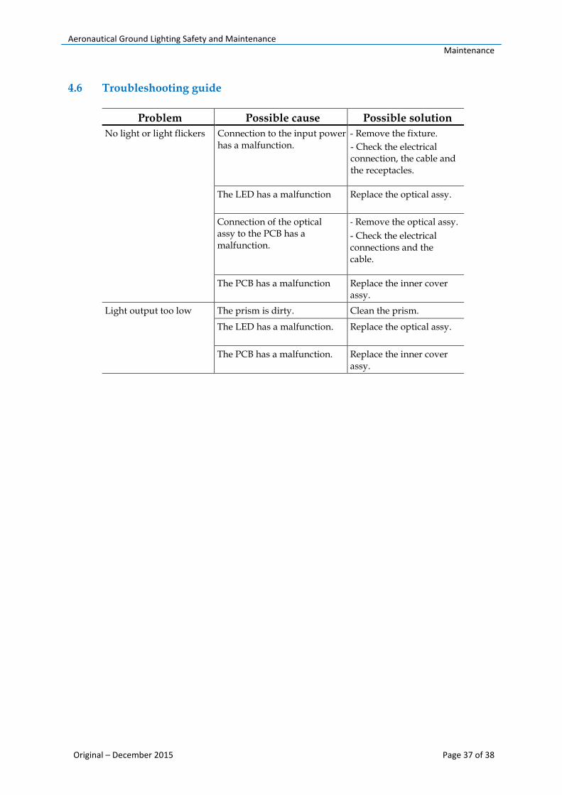
4.6 Troubleshooting guide
Problem Possible cause Possible solution
No light or light flickers Connection to the input power has a malfunction.
- Remove the fixture.
- Check the electrical connection, the cable and the receptacles.
The LED has a malfunction Replace the optical assy.
Connection of the optical assy to the PCB has a malfunction.
- Remove the optical assy.
- Check the electrical connections and the cable.
The PCB has a malfunction Replace the inner cover assy.
Light output too low The prism is dirty. Clean the prism.
The LED has a malfunction. Replace the optical assy.
The PCB has a malfunction. Replace the inner cover assy.

Aeronautical Ground Lighting Safety and Maintenance Bibliography
Original – December 2015 Page 38 of 38
Bibliography
Regulation No 01/2008 on Aerodromes (as amended);
ICAO Annex 14 Aerodromes (Volume I)
ICAO Doc 9137 - Airport Services Manual Part 9 - Airport Maintenance Practices
CAP 637 - Visual Aids Handbook (UK CAA)
IDMAN – Airfield Lighting Manual
ADB – AGL Instruction Manual
LPI - Lightning Protection Institute