towards the modelling of anisotropic solids
TRANSCRIPT
COMPUTATIONAL METHODS IN SCIENCE AND TECHNOLOGY 16(1), 73-84 (2010)
I. INTRODUCTION Modern industrial requirements and a constant process of designing new metals induce the necessity of developing sophisticated mathematical models describing them. It is because today during the investment process, there is no time to prepare real prototypes (it is also economically unjustified); thus the ability of mathematical (numerical) modelling is fundamental. Taking common applications of metals, e.g. cars, trucks, cranes, bridges, naval surface vessels, submarines, the importance of the above state-ments is easily understood.
A growing interest of the industry in the field of (con-tinuum) damage mechanics is focused on including the new physical phenomena (viscoplastic, rate dependent behav-iour). These phenomena can be relatively easily modelled and the obstacles connected could be overcome by using, e.g. common finite element codes. The complexity of the problem lays in the fact that the properly (in qua-
litative and quantitative sense) defined mathematical model describing the damage phenomena in metals needs a de-tailed description reaching micro scale observations. As a consequence anisotropy of metal structure must be included into the model. Metals anisotropy in the mathematical model has deep consequences in numerical applications for practical in-dustrial problems. The most important, in contrast to the iso-tropic one, are: (i) additional material parameters to be identified, (ii) additional variables to be calculated, and (iii) the necessity of full spatial modelling. Thus real applications very often lead to analyses with over several (or even hundreds) million degrees of freedom. To solve the problem in an acceptable time (e.g. one or two weeks), it is then necessary to apply supercomputers with hundreds of processors and disk space reaching hundreds of terabytes. In the paper we present both the theory describing metals anisotropy and its numerical implementation. The mate-rial model is stated in terms of continuum mechanics,
Towards the Modelling of Anisotropic Solids
Adam Glema, Tomasz Łodygowski, Wojciech Sumelka
Poznan University of Technology
Faculty of Civil and Environmental Engineering Institute of Structural Engineering, Division of Computer Aided Design
ul. Piotrowo 5, 60-965 Poznań, Poland
e-mail: {Adam.Glema/Tomasz.Lodygowski/Wojciech.Sumelka}@put.poznan.pl
(Received: 13 January 2010; revised: 24 February 2010; accepted: 10 March 2010; published online: 7 May 2010)
Abstract: In the paper the material model for metals and its numerical applications are presented. The material model is statedin terms of continuum mechanics, in the framework of the thermodynamical theory of viscoplasticity. The fundamental achievementis that the constitutive relation includes a description of anisotropy of metal microstructure. Such approach gives qualitativelyand quantitatively new results compared with the existing models because it is possible to trace the directions of softeningand predict a damage path in process time. Numerical examples comprise full spatial modelling for HSLA-65 steel in adiabatic conditions (the analysis of anisotropic bodies can be led only on 3D models) including: tension of sheet steel and twisting of thinwalled tube. During analyses strain rates of order 104-107 s–1 are observed and the process time up to full damage (loss of continuityin the localisation zone) is around 100-300 μs. Key words: anisotropy, metals, constitutive relation
A. Glema, T. Łodygowski, W. Sumelka 74
in the framework of the thermodynamical theory of visco-plasticity together with a phenomenological approach [36, 11, 43]. Formally, the constitutive structure belongs to the class of simple materials with fading memory, and due to its final form and the way of incorporating the fun-damental variables, belongs to the materials of rate type with internal state variables [44]. The implementation is done in the Abaqus/Explicit finite element code, utilising a capability of user subroutine VUMAT, and applied to a numerical solution of highly dynamic processes under adiabatic conditions (strain rates of the order 104÷107 s–1). Two examples are analysed: tension of sheet steel and twisting of thin walled tube. Theoretical and numerical parts are preceded by a short summary of crucial ex-perimental results that stress the fundamental role of metals anisotropy in the process of deformation up to full damage (loss of continuity in the localisation zone).
II. METALS ANISOTROPY Let us focus on experimental observations of metals anisotropy caused by the anisotropic nature of the micro-damages (or microdefects). In the discussion we omit other sources of metals anisotropy, like e.g. kinematical harden-ing or well recognised and described phenomena during metals deformation, like rate sensitivity, length scale sensitivity or plastic non-normality. For detailed informa-tion, please see the review reports, e.g. [21, 33, 8]. The experimental observations of metals can be gath-ered in the following three main statements:
(i) metals are anisotropic, (ii) intrinsic microdefects are not isotropic, (iii) evolution of microdamage is directional.
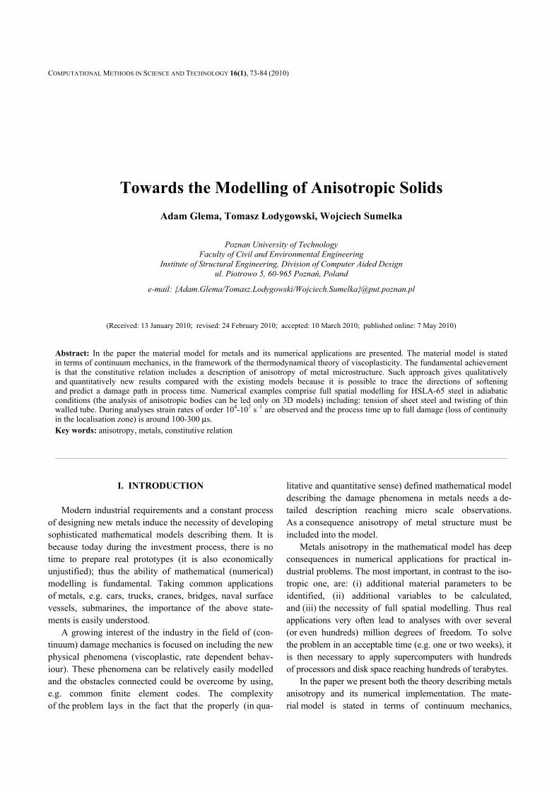
Statement (i) reflects the fact that the internal structure of metals is never free of the inhomogeneities. Metals microstructure shows different sizes and shapes of adjacent grains [16], presence of different phases like pearlite or ferrite [26], or existence of defects like microcracks, micro-voids, mobile and immobile dislocations densities [2, 45] (cf. Fig. 1). The inhomogeneities of metals structure indicate their anisotropic character, evolving dependent on the analysed process. We can classify them in two sources of metals anisotropy: the first linked with disorders of microstructure itself and the second associated with the existence of intrinsic defects. For mathematical modelling purposes, at the continuum level of description, the material model for metals should manifest the anisotropic properties. The frequently used iso-tropic descriptions for metals should be thought of as the first approximation which carries not enough information (though
Fig. 1. The anisotropy of the HSLA-65 steel microstructure
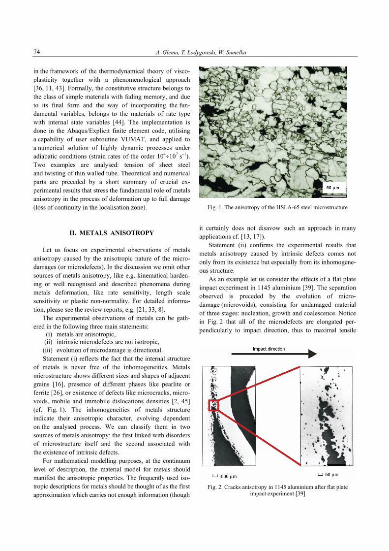
it certainly does not disavow such an approach in many applications cf. [13, 17]). Statement (ii) confirms the experimental results that metals anisotropy caused by intrinsic defects comes not only from its existence but especially from its inhomogene-ous structure. As an example let us consider the effects of a flat plate impact experiment in 1145 aluminium [39]. The separation observed is preceded by the evolution of micro-damage (microvoids), consisting for undamaged material of three stages: nucleation, growth and coalescence. Notice in Fig. 2 that all of the microdefects are elongated per-pendicularly to impact direction, thus to maximal tensile
Fig. 2. Cracks anisotropy in 1145 aluminium after flat plate
impact experiment [39]
Towards the Modelling of Anisotropic Solids 75
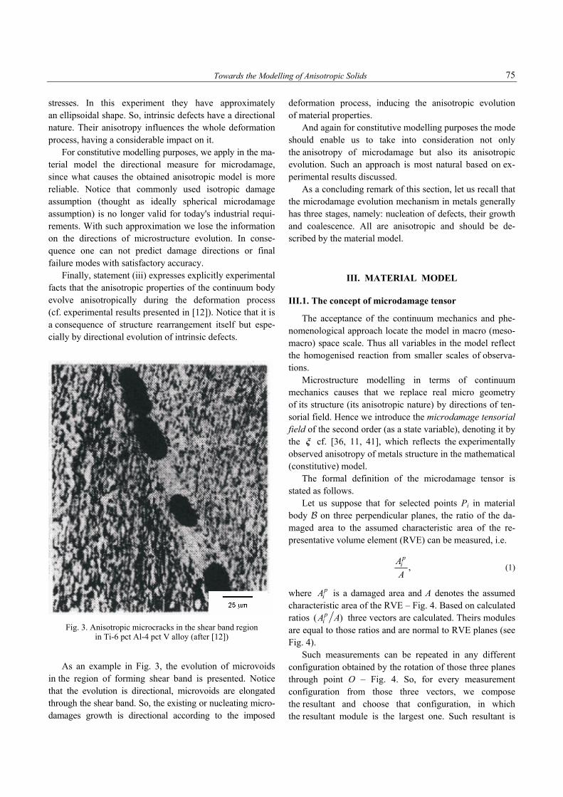
stresses. In this experiment they have approximately an ellipsoidal shape. So, intrinsic defects have a directional nature. Their anisotropy influences the whole deformation process, having a considerable impact on it. For constitutive modelling purposes, we apply in the ma-terial model the directional measure for microdamage, since what causes the obtained anisotropic model is more reliable. Notice that commonly used isotropic damage assumption (thought as ideally spherical microdamage assumption) is no longer valid for today's industrial requi-rements. With such approximation we lose the information on the directions of microstructure evolution. In conse-quence one can not predict damage directions or final failure modes with satisfactory accuracy. Finally, statement (iii) expresses explicitly experimental facts that the anisotropic properties of the continuum body evolve anisotropically during the deformation process (cf. experimental results presented in [12]). Notice that it is a consequence of structure rearrangement itself but espe-cially by directional evolution of intrinsic defects.
Fig. 3. Anisotropic microcracks in the shear band region
in Ti-6 pct Al-4 pct V alloy (after [12])
As an example in Fig. 3, the evolution of microvoids in the region of forming shear band is presented. Notice that the evolution is directional, microvoids are elongated through the shear band. So, the existing or nucleating micro-damages growth is directional according to the imposed
deformation process, inducing the anisotropic evolution of material properties. And again for constitutive modelling purposes the mode should enable us to take into consideration not only the anisotropy of microdamage but also its anisotropic evolution. Such an approach is most natural based on ex-perimental results discussed. As a concluding remark of this section, let us recall that the microdamage evolution mechanism in metals generally has three stages, namely: nucleation of defects, their growth and coalescence. All are anisotropic and should be de-scribed by the material model.
III. MATERIAL MODEL
III.1. The concept of microdamage tensor
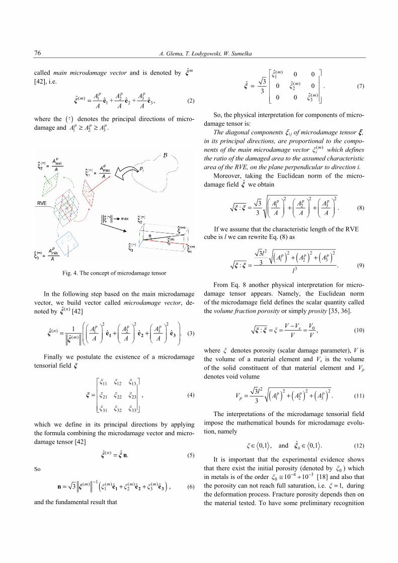
The acceptance of the continuum mechanics and phe-nomenological approach locate the model in macro (meso-macro) space scale. Thus all variables in the model reflect the homogenised reaction from smaller scales of observa-tions. Microstructure modelling in terms of continuum mechanics causes that we replace real micro geometry of its structure (its anisotropic nature) by directions of ten-sorial field. Hence we introduce the microdamage tensorial field of the second order (as a state variable), denoting it by the ξ cf. [36, 11, 41], which reflects the experimentally observed anisotropy of metals structure in the mathematical (constitutive) model. The formal definition of the microdamage tensor is stated as follows. Let us suppose that for selected points Pi in material body B on three perpendicular planes, the ratio of the da-maged area to the assumed characteristic area of the re-presentative volume element (RVE) can be measured, i.e.
,p
iAA
(1)
where piA is a damaged area and A denotes the assumed
characteristic area of the RVE – Fig. 4. Based on calculated ratios ( )p
iA A three vectors are calculated. Theirs modules are equal to those ratios and are normal to RVE planes (see Fig. 4). Such measurements can be repeated in any different configuration obtained by the rotation of those three planes through point O – Fig. 4. So, for every measurement configuration from those three vectors, we compose the resultant and choose that configuration, in which the resultant module is the largest one. Such resultant is
A. Glema, T. Łodygowski, W. Sumelka 76
called main microdamage vector and is denoted by ˆmξ [42], i.e.
( ) 31 21 2 3
ˆ ˆ ˆ ˆ+ + ,pp p
m AA AA A A
= e e eξ (2)
where the ( )⋅ denotes the principal directions of micro-damage and 1 2 3 .p p pA A A≥ ≥
Fig. 4. The concept of microdamage tensor
In the following step based on the main microdamage vector, we build vector called microdamage vector, de-noted by ( )ˆ nξ [42]
22 2
( ) 31 2( )1ˆ ˆ ˆ ˆ .ˆ
pp pn
m
AA AA A A
⎛ ⎞⎛ ⎞⎛ ⎞ ⎛ ⎞⎜ ⎟= + + ⎜ ⎟⎜ ⎟ ⎜ ⎟⎜ ⎟ ⎜ ⎟ ⎜ ⎟⎜ ⎟⎝ ⎠ ⎝ ⎠ ⎝ ⎠⎝ ⎠1 2 3e e eξ
ξ (3)
Finally we postulate the existence of a microdamage tensorial field ξ
11 12 13
21 22 23
31 32 33
,
ξ ξ ξ
ξ ξ ξ
ξ ξ ξ
⎡ ⎤⎢ ⎥
= ⎢ ⎥⎢ ⎥⎢ ⎥⎣ ⎦
ξ (4)
which we define in its principal directions by applying the formula combining the microdamage vector and micro-damage tensor [42]
( )ˆ ˆ .n = nξ ξ (5)
So
( )1( ) ( ) ( ) ( )2 3ˆ ˆ ˆ3 ,m m m mξ ξ ξ
−= + +1 2 3n e e eξ 1 (6)
and the fundamental result that
( )1
( )2
( )3
ˆ 0 03ˆ ˆ0 0 .
3ˆ0 0
m
m
m
ξ
ξ
ξ
⎡ ⎤⎢ ⎥
= ⎢ ⎥⎢ ⎥⎢ ⎥⎣ ⎦
ξ (7)
So, the physical interpretation for components of micro-damage tensor is: The diagonal components > i j of microdamage tensor > , in its principal directions, are proportional to the compo-nents of the main microdamage vector ( )m
iξ which defines the ratio of the damaged area to the assumed characteristic area of the RVE, on the plane perpendicular to direction i. Moreover, taking the Euclidean norm of the micro-damage field ξ we obtain
22 2
31 23: .3
pp p AA AA A A
⎛ ⎞⎛ ⎞ ⎛ ⎞= + + ⎜ ⎟⎜ ⎟ ⎜ ⎟⎜ ⎟ ⎜ ⎟ ⎜ ⎟
⎝ ⎠ ⎝ ⎠ ⎝ ⎠ξ ξ (8)
If we assume that the characteristic length of the RVE cube is l we can rewrite Eq. (8) as
( ) ( ) ( )
2 2 2 21 2 3
3
33: .
p p pl A A A
l
+ +=ξ ξ (9)
From Eq. 8 another physical interpretation for micro-damage tensor appears. Namely, the Euclidean norm of the microdamage field defines the scalar quantity called the volume fraction porosity or simply prosity [35, 36].
0: ,sV V VξV V−= = =ξ ξ (10)
where ξ denotes porosity (scalar damage parameter), V is the volume of a material element and Vs is the volume of the solid constituent of that material element and Vp denotes void volume
( ) ( ) ( )2 2 2 2
1 2 33 .3
p p pp
lV A A A= + + (11)
The interpretations of the microdamage tensorial field impose the mathematical bounds for microdamage evolu-tion, namely
ˆ0,1 , and 0,1 .iiξ∈ ∈ξ (12)
It is important that the experimental evidence shows that there exist the initial porosity (denoted by 0ξ ) which in metals is of the order 4 3
0 10 10ξ − −≅ ÷ [18] and also that the porosity can not reach full saturation, i.e. 1,ξ = during the deformation process. Fracture porosity depends then on the material tested. To have some preliminary recognition
Towards the Modelling of Anisotropic Solids 77
for metals, notice that the fracture porosity for them is of order 0.09÷0.035 [5-7]. III.2. Constitutive model for an adiabatic process
In the theory, as mentioned, continuum mechanics with phenomenological approach are accepted. The abstract body is a differential manifold. Because the description operates in spatial configuration Lie time derivative is used to obtain an objective model (in the sense of spatial covariance [15] – in other words independent of the “ob-server”. Below the fundamental results for an adiabatic process are given; for a detailed and more general formu-lation please see [41]. In the kinematics of the body, finite elasto-viscoplastic deformation is governed by the multiplicative decomposi-tion of the total deformation gradient to elastic and visco-plastic parts [14, 32]
( , ) ( , ) ( , ).e pt t t= ⋅F X F X F X (13)
In (13)
( ),
,tφ∂
=∂
XF
X
is deformation gradient, φ is motion, X denotes material coordinates, t is time and Fe, Fp are elastic and viscoplastic parts, respectively. For further definition of the rate type constitutive structure let us define the rate of deformation. Starting from spatial deformation gradient denoted by l
( , )( , ) ,tt ∂=∂xl xx
υ (14)
where υ denotes spatial velocity and x are spatial coordi-nates, by its decomposition to symmetric and antisym-metric parts, we obtain
,e e p p= + = + + +l d w d w d w (15)
( )1 ,2
T= +d l l (16)
( )1 .2
T= −w l l (17)
Now taking Lie derivative of the assumed strain meas-ure (the Euler-Almansi strain) we have the fundamental relation ( )L ,=d eb b
υ (18)
and simultaneously
( ) ( )L , L ,e e p p= =d e d eb b b b υ υ (19)
where Lυ stands for Lie derivative and e for the Euler-Almansi strain, showing that the symmetric part of spatial deformation gradient is directly Lie derivative of the Euler-Almansi strain. Next, assuming that balance principles hold, namely: conservation of mass, balance of momentum, balance of the moment of momentum and balance of energy and entropy production inequality is satisfied, we define four constitutive postulates. We have the following axioms [34]: (i) Existence of the free energy function ψ. Formally
we apple the following form
( ), , , ,ψ ψ ϑ= e F μ
where μ denotes a set of internal state variables, that governs the description of dissipation effects, and h is temperature.
(ii) Axiom of objectivity (spatial covariance). The ma-terial model should be invariant with respect to any superposed motion (diffeomorphism). It is proved [15] that the consequently used Lie derivative for all rates in the constitutive structure assures the covariance.
(iii) The axiom of the entropy production. For every regular process the constitutive functions should satisfy the second law of thermodynamics.
(iv) The evolution equation for the internal state variable vector μ should be of the form
ˆL = mμυ (e, F, h, :),
where evolution function m has to be determined based on the experimental observations; notice, that the determination of m appears the most challeng-ing problem in modern constitutive modelling.
The explicit statement of a complete set of governing equations for an adiabatic process is preceded by an ad-ditional assumptions. So, for an adiabatic process we postulate as follows (cf. [5, 6, 34, 9, 43, 41]): (i) microdamage does not influence considerably
the elastic range, (ii) in every material point of the body there exists
an initial microdamage state, (iii) conductivity and thermo-elastic effects are omitted. Assuming that the above hold, the deforming body under the adiabatic regime is governed by the following set of equations. They state the initial boundary value problem (IBVP). Find N, L, D, τ, >, h as a function of t and x such that [31, 21, 23, 24]:
(i) the field equations
= ,υφ
A. Glema, T. Łodygowski, W. Sumelka 78
( )( )1/ 2
1/ 21 div grad grad : ,
1 :Refυ ρ
ρ ρ
⎛ ⎞⎜ ⎟= ⋅ − ⋅⎜ ⎟−⎝ ⎠
+ ξ ξξ ξ
τ ττ
( )( )1/2
1/2div L : L ,1 :
ρρ ρ= −−
υ+ ξ ξξ ξ
υ υ
( ): 2 : ,e th e p= + ⋅ − − + +d d g g dϑτ τ τ τL L L (22)
( )* 12 1 ,
, ,gg
pm eq
IgT
⎡ ⎤∂ ⎢ ⎥= ⋅ + Φ −∂ ⎢ ⎥ϑ ∈⎣ ⎦
dτ τ
ξ ξξ
* **: : L ,p
p p
χ χρc ρc
= +d kϑ τ υξ
(ii) the boundary conditions a) displacement N is prescribed on a part ΓN of Γ(B)
and tractions ( )a⋅nτ are prescribed on part Γτ of Γ(B), where ΓN ∩ Γτ = 0 and ΓN ∪ Γτ = Γ(B),
b) heat flux q ⋅ n = 0 is prescribed on Γ(B), (iii) the initial conditions N, L, D, τ, >, h are given
at each particle ∈X B at t = 0, are satisfied. Above we have denoted: ρRef a referential density, τ the Kirchhoff stress tensor, ρ a current density, Le an elastic constitutive tensor, Lth a thermal operator, g a metric tensor, *g∂ ∂τ the evolution directions for an-isotropic microdamage growth processes, Tm a relaxation time, Ig a stress intensity invariant, τeq the threshold stress, X *, X ** the irreversibility coefficients and cp a specific heat.
For the evolution problem (22) we assume as follows: 1. For elastic constitutive tensor L e
( )2 ,e μ λ= + ⊗g gL I (23)
where μ, λ are Lamé constants. 2. For thermal operator Lth
( )2 3 ,th μ λ θ= + gL (24)
where θ is thermal expansion coefficient. 3. For viscoplastic flow phenomenon d p [27, 28]
,p υp= Λd p (25)
where
1 11 1 ,plm
υp υp
m m
f fT κ T κ
⎛ ⎞ ⎛ ⎞Λ = Φ − = −⎜ ⎟ ⎜ ⎟⎝ ⎠ ⎝ ⎠
(26)
( ){ }1/21/2' 22 1 2 1
1 2
( ) ( ) : ,
( ) 0, ( ) const,
f J n n J
n n n
⎡ ⎤= + +⎣ ⎦= ϑ = =
ϑ ϑ
ϑ
ξ ξ (27)
[ ]{ }
( )
0
( )1/2
( ) ( ) ( ) exp ( )
:1 ,
ps s
F
⎡ ⎤= − − − ∈ ⋅⎣ ⎦
⎡ ⎤⎛ ⎞⎢ ⎥⎜ ⎟⋅ − ⎜ ⎟⎢ ⎥⎝ ⎠⎣ ⎦
β ϑ
κ κ ϑ κ ϑ κ ϑ δ ϑ
ξξ ξ
(28)
* ** * **0 0 0
* ** * **
* **
( ) ( )
( ) , ( ) ,
,
L L,
L
F
s s s
mcF F F
c
0
0
= − = −
= − = −
−=
⎛ ⎞−= − ⎜ ⎟⎜ ⎟
⎝ ⎠
κ ϑ κ κ ϑ, κ ϑ κ κ ϑ,
δ ϑ δ δ ϑ β ϑ β β ϑ
ϑ ϑϑϑ
ξ ξ ξ υ υ
υ
ξ ξξ
( )[ ]
1
const
1/22' 22
1 ' + tr ,2 3 tr
f f
J A
−
=
⎛ ⎞∂ ∂= =⎜ ⎟∂ ∂⎝ ⎠
=⎡ ⎤+⎣ ⎦
p
δ
τ τ
τ ττ
Α
ξ (29)
and f denotes potential function [40, 30, 29, 11], κ is isotropic work-hardening-softening function [30, 19, 10], τ' stress deviator, J1, '
2J are first second in-variants of Kirchhoff stress tensor and deviatoric part of the Kirchhoff stress tensor, respectively;
( )( )1/21 22 : ,A n n= + ξ ξ
> F* can be thought as quasistatic fracture porosity and L cυξ denotes equivalent critical velocity of micro-
damage. 4. For the microdamage mechanism taking additional
assumptions [4, 10, 11]: • increment of the microdamage state is coaxial with
principal directions of stress state, • only positive principal stresses induces the growth
of the microdamage, we have
1* ˆ ˆ 1ˆ, and : :
2g g g g
−∂ ∂ ∂= =∂ ∂ ∂
τ ττ τ τ
G , (30)
( ) 1 1 ,, ,
mdmg gg
peqeq
I I⎛ ⎞ ⎛ ⎞⎜ ⎟Φ − = −⎜ ⎟⎜ ⎟⎜ ⎟∈ ⎝ ⎠⎝ ⎠
ττ ϑξ (31)
where
Towards the Modelling of Anisotropic Solids 79
( )( ) ( )
[ ]{ }
1/21/2
0 0
1( ) 1 : ln:
2 ( ) ( ) ( ) ( , , ) ,
eq
s s
c
κ κ κ F ξ
= − ×
× − −
ϑ
ϑ ϑ ϑ ϑ
τ ξ ξξ ξ
ξ (32)
( ) const,c =ϑ
( )( )
( )
21/2 3
01/2
0
21/2 3
0
1 :1 :
1 :,
1
δ
δ
ξFξ
ξ
⎛ ⎞−⎜ ⎟= +⎜ ⎟−⎝ ⎠
⎛ ⎞−⎜ ⎟+⎜ ⎟−⎝ ⎠
ξ ξ
ξ ξ
ξ ξ
(33)
and
( ) ( )1/2 1/3' '1 1 2 2 3 3 .gI b J b J b J= + + (34)
ib (i = 1, 2, 3) are the material parameters, '3J is
the third invariant of a deviatoric part of the Kirchhoff stress tensor. Taking those fundamental postulates into account, and assuming that tensor G can be written as a symmetric part of the fourth order unity tensor I [22], thus
( )1, ,2
sijkl ik jl il jkδ δ δ δ= = +G I G (35)
we can write the explicit form of the growth function g as
( )2 2 2I II III
1ˆ ,2
g = + +τ τ τ (36)
and the gradient of g with respect to the stress field gives us the following matrix representation of a tensor describing the anisotropic evolution of microdamage
11 I
22 II
33 III
0 00 0 ,0 0
gg g
g
⎡ ⎤∂ ⎢ ⎥= ⎢ ⎥∂
⎢ ⎥⎣ ⎦τ
ττ
τ (37)
where τI, τII, τIII are the principal values of Kirchhoff stress tensor. Notice that the definition of the threshold stress for microcrack growth function τeq indicates that the growth term in evolution function for microdamage is active only after nucleation – before nucleation we have in-finite threshold 0lim .eq→ = ∞ξ τ
5. For temperature evolution Eq. (22) we take
=k τ. (38)
Notice that the regularization evolution problem (22) is well-posed [25, 20, 21]. The relaxation time Tm can be
viewed as a regularization parameter which introduces implicitly the length scale. Thus, it can be proved [21, 8] that a so called Cauchy problem defined above has a unique and stable solution.
IV. NUMERICAL EXAMPLES IV.1. Introductory remarks
The common aim of a thermomechanical analysis is to determine the stress, strain (its elastic and viscoplastic parts) and thermal fields during the deformation process. The damage mechanics of solids introduces additional measures which enables tracing of the damage progress. In the proposed formulation, as mentioned, the novelty is that we can trace softening directions. Such description gives qualitatively and quantitatively new results. Knowing homogenised microstructure rearrangement directions, we can more precisely establish softening zones and in con-sequence mode of failure (loss of continuity) – which is fundamental from the point of view of modern industrial requirements. The solution of the IBVP defined by Eqs. (22) has been obtained by using the finite element method. The Abaqus/-Explicit commercial finite element code has been adapted as a solver. The model has been implemented in the soft-ware by taking advantage of user subroutine VUMAT, which is coupled with the Abaqus system [1]. For a de-tailed algorithm please see [41]. IV.2. Numerical identification
To solve the IBVP defined by Eqs. (22), one has to de-termine 28 unknown parameters that characterise the ana-lysed material (steel). In Table 1 we present a complete set of parameters (identified in a sense of numerical calibration) for HSLA-65 steel. The identification proce-dure bases on results obtained experimentally in [17]. The HSLA-65 steel belongs to the class of HSLA steels (High-Strength Low-Alloy) which were developed in 1960s. The high strength of this steel (flow stresses are in the rage 400÷1200 MPa dependently on temperature) connected with good weldability, formability, thoughtness, elevated service life, less weight to the traditional high-strength steel, cause the broad range of its nowadays applications e.g. cars, trucks, cranes, bridges, naval surface vessels, submarines and other structures that are designed to handle large amounts of material efforts, frequently subjected to wide range of temperatures [38]. The steel has the characteristics of the bcc structure, hence belongs to so called ferritic steels. As a consequence this metal has high
A. Glema, T. Łodygowski, W. Sumelka 80
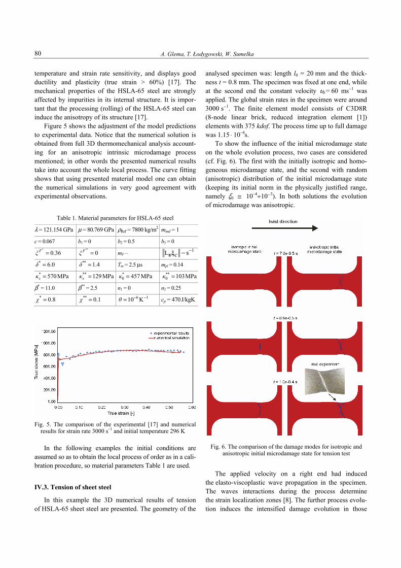
temperature and strain rate sensitivity, and displays good ductility and plasticity (true strain > 60%) [17]. The mechanical properties of the HSLA-65 steel are strongly affected by impurities in its internal structure. It is impor-tant that the processing (rolling) of the HSLA-65 steel can induce the anisotropy of its structure [17]. Figure 5 shows the adjustment of the model predictions to experimental data. Notice that the numerical solution is obtained from full 3D thermomechanical analysis account-ing for an anisotropic intrinsic microdamage process mentioned; in other words the presented numerical results take into account the whole local process. The curve fitting shows that using presented material model one can obtain the numerical simulations in very good agreement with experimental observations.
Table 1. Material parameters for HSLA-65 steel
λ = 121.154 GPa μ = 80.769 GPa ρRef = 7800 kg/m2 mmd = 1
c = 0.067 b1 = 0 b2 = 0.5 b3 = 0 *
0.36Fξ = **
0Fξ = mF – 1L s c −−ξυ* 6.0δ = ** 1.4δ = Tm = 2.5 μs mpl = 0.14 * 570MPasκ = ** 129 MPasκ = *
0 457 MPaκ = **0 103MPaκ =
β* = 11.0 β** = 2.5 n1 = 0 n2 = 0.25 * 0.8χ = ** 0.1χ = 6 110 Kθ − −= cp = 470J/kgK
Fig. 5. The comparison of the experimental [17] and numerical results for strain rate 3000 s–1 and initial temperature 296 K In the following examples the initial conditions are assumed so as to obtain the local process of order as in a cali-bration procedure, so material parameters Table 1 are used.
IV.3. Tension of sheet steel
In this example the 3D numerical results of tension of HSLA-65 sheet steel are presented. The geometry of the
analysed specimen was: length l0 = 20 mm and the thick-ness t = 0.8 mm. The specimen was fixed at one end, while at the second end the constant velocity L0 = 60 ms–1 was applied. The global strain rates in the specimen were around 3000 s–1. The finite element model consists of C3D8R (8-node linear brick, reduced integration element [1]) elements with 375 kdof. The process time up to full damage was 1.15 ⋅ 10–4s. To show the influence of the initial microdamage state on the whole evolution process, two cases are considered (cf. Fig. 6). The first with the initially isotropic and homo-geneous microdamage state, and the second with random (anisotropic) distribution of the initial microdamage state (keeping its initial norm in the physically justified range, namely >0 ≅ 10–4÷10–3). In both solutions the evolution of microdamage was anisotropic.
Fig. 6. The comparison of the damage modes for isotropic and
anisotropic initial microdamage state for tension test
The applied velocity on a right end had induced the elasto-viscoplastic wave propagation in the specimen. The waves interactions during the process determine the strain localization zones [8]. The further process evolu-tion induces the intensified damage evolution in those
Towards the Modelling of Anisotropic Solids 81
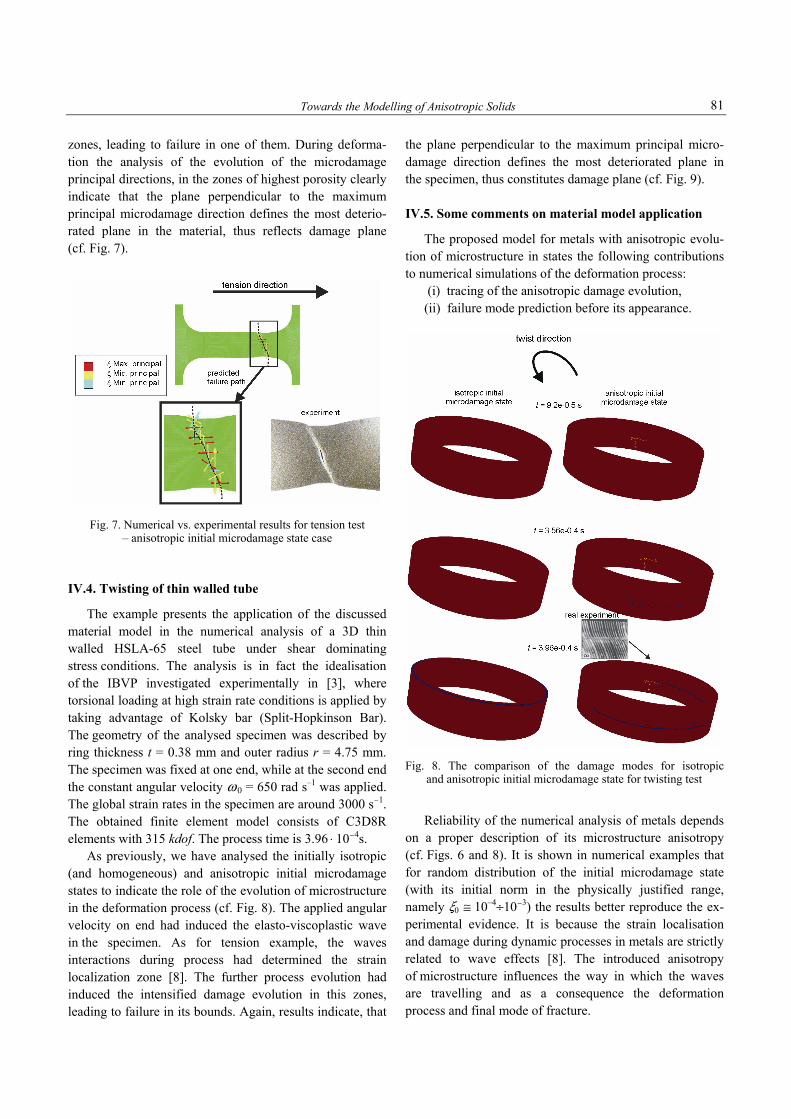
zones, leading to failure in one of them. During deforma-tion the analysis of the evolution of the microdamage principal directions, in the zones of highest porosity clearly indicate that the plane perpendicular to the maximum principal microdamage direction defines the most deterio-rated plane in the material, thus reflects damage plane (cf. Fig. 7).
Fig. 7. Numerical vs. experimental results for tension test – anisotropic initial microdamage state case
IV.4. Twisting of thin walled tube
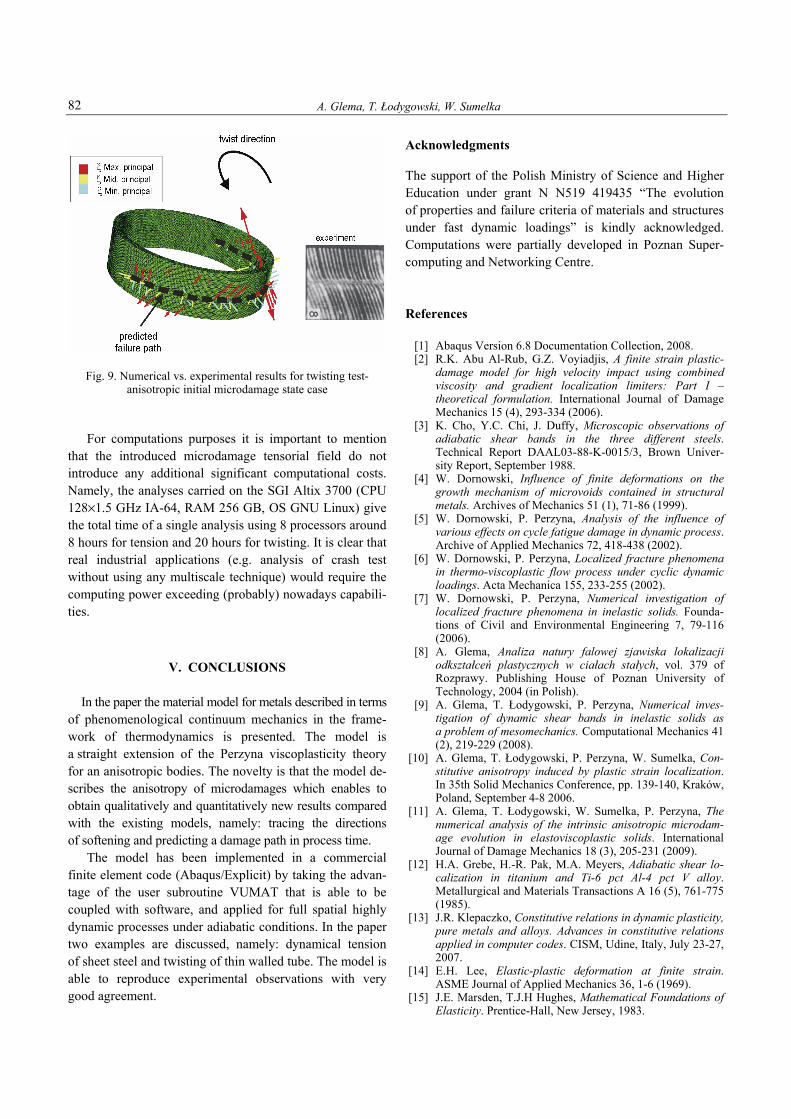
The example presents the application of the discussed material model in the numerical analysis of a 3D thin walled HSLA-65 steel tube under shear dominating stress conditions. The analysis is in fact the idealisation of the IBVP investigated experimentally in [3], where torsional loading at high strain rate conditions is applied by taking advantage of Kolsky bar (Split-Hopkinson Bar). The geometry of the analysed specimen was described by ring thickness t = 0.38 mm and outer radius r = 4.75 mm. The specimen was fixed at one end, while at the second end the constant angular velocity ω 0 = 650 rad s–1 was applied. The global strain rates in the specimen are around 3000 s–1. The obtained finite element model consists of C3D8R elements with 315 kdof. The process time is 3.96 ⋅ 10–4s. As previously, we have analysed the initially isotropic (and homogeneous) and anisotropic initial microdamage states to indicate the role of the evolution of microstructure in the deformation process (cf. Fig. 8). The applied angular velocity on end had induced the elasto-viscoplastic wave in the specimen. As for tension example, the waves interactions during process had determined the strain localization zone [8]. The further process evolution had induced the intensified damage evolution in this zones, leading to failure in its bounds. Again, results indicate, that
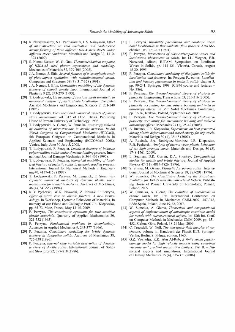
the plane perpendicular to the maximum principal micro-damage direction defines the most deteriorated plane in the specimen, thus constitutes damage plane (cf. Fig. 9). IV.5. Some comments on material model application
The proposed model for metals with anisotropic evolu-tion of microstructure in states the following contributions to numerical simulations of the deformation process: (i) tracing of the anisotropic damage evolution, (ii) failure mode prediction before its appearance.
Fig. 8. The comparison of the damage modes for isotropic and anisotropic initial microdamage state for twisting test
Reliability of the numerical analysis of metals depends on a proper description of its microstructure anisotropy (cf. Figs. 6 and 8). It is shown in numerical examples that for random distribution of the initial microdamage state (with its initial norm in the physically justified range, namely >0 ≅ 10–4÷10–3) the results better reproduce the ex-perimental evidence. It is because the strain localisation and damage during dynamic processes in metals are strictly related to wave effects [8]. The introduced anisotropy of microstructure influences the way in which the waves are travelling and as a consequence the deformation process and final mode of fracture.
A. Glema, T. Łodygowski, W. Sumelka 82
Fig. 9. Numerical vs. experimental results for twisting test- anisotropic initial microdamage state case
For computations purposes it is important to mention that the introduced microdamage tensorial field do not introduce any additional significant computational costs. Namely, the analyses carried on the SGI Altix 3700 (CPU 128×1.5 GHz IA-64, RAM 256 GB, OS GNU Linux) give the total time of a single analysis using 8 processors around 8 hours for tension and 20 hours for twisting. It is clear that real industrial applications (e.g. analysis of crash test without using any multiscale technique) would require the computing power exceeding (probably) nowadays capabili-ties.
V. CONCLUSIONS
In the paper the material model for metals described in terms of phenomenological continuum mechanics in the frame-work of thermodynamics is presented. The model is a straight extension of the Perzyna viscoplasticity theory for an anisotropic bodies. The novelty is that the model de-scribes the anisotropy of microdamages which enables to obtain qualitatively and quantitatively new results compared with the existing models, namely: tracing the directions of softening and predicting a damage path in process time. The model has been implemented in a commercial finite element code (Abaqus/Explicit) by taking the advan-tage of the user subroutine VUMAT that is able to be coupled with software, and applied for full spatial highly dynamic processes under adiabatic conditions. In the paper two examples are discussed, namely: dynamical tension of sheet steel and twisting of thin walled tube. The model is able to reproduce experimental observations with very good agreement.
Acknowledgments The support of the Polish Ministry of Science and Higher Education under grant N N519 419435 “The evolution of properties and failure criteria of materials and structures under fast dynamic loadings” is kindly acknowledged. Computations were partially developed in Poznan Super-computing and Networking Centre. References [1] Abaqus Version 6.8 Documentation Collection, 2008. [2] R.K. Abu Al-Rub, G.Z. Voyiadjis, A finite strain plastic-
damage model for high velocity impact using combined viscosity and gradient localization limiters: Part I – theoretical formulation. International Journal of Damage Mechanics 15 (4), 293-334 (2006).
[3] K. Cho, Y.C. Chi, J. Duffy, Microscopic observations of adiabatic shear bands in the three different steels. Technical Report DAAL03-88-K-0015/3, Brown Univer-sity Report, September 1988.
[4] W. Dornowski, Influence of finite deformations on the growth mechanism of microvoids contained in structural metals. Archives of Mechanics 51 (1), 71-86 (1999).
[5] W. Dornowski, P. Perzyna, Analysis of the influence of various effects on cycle fatigue damage in dynamic process. Archive of Applied Mechanics 72, 418-438 (2002).
[6] W. Dornowski, P. Perzyna, Localized fracture phenomena in thermo-viscoplastic flow process under cyclic dynamic loadings. Acta Mechanica 155, 233-255 (2002).
[7] W. Dornowski, P. Perzyna, Numerical investigation of localized fracture phenomena in inelastic solids. Founda-tions of Civil and Environmental Engineering 7, 79-116 (2006).
[8] A. Glema, Analiza natury falowej zjawiska lokalizacji odkształceń plastycznych w ciałach stałych, vol. 379 of Rozprawy. Publishing House of Poznan University of Technology, 2004 (in Polish).
[9] A. Glema, T. Łodygowski, P. Perzyna, Numerical inves-tigation of dynamic shear bands in inelastic solids as a problem of mesomechanics. Computational Mechanics 41 (2), 219-229 (2008).
[10] A. Glema, T. Łodygowski, P. Perzyna, W. Sumelka, Con-stitutive anisotropy induced by plastic strain localization. In 35th Solid Mechanics Conference, pp. 139-140, Kraków, Poland, September 4-8 2006.
[11] A. Glema, T. Łodygowski, W. Sumelka, P. Perzyna, The numerical analysis of the intrinsic anisotropic microdam-age evolution in elastoviscoplastic solids. International Journal of Damage Mechanics 18 (3), 205-231 (2009).
[12] H.A. Grebe, H.-R. Pak, M.A. Meyers, Adiabatic shear lo-calization in titanium and Ti-6 pct Al-4 pct V alloy. Metallurgical and Materials Transactions A 16 (5), 761-775 (1985).
[13] J.R. Klepaczko, Constitutive relations in dynamic plasticity, pure metals and alloys. Advances in constitutive relations applied in computer codes. CISM, Udine, Italy, July 23-27, 2007.
[14] E.H. Lee, Elastic-plastic deformation at finite strain. ASME Journal of Applied Mechanics 36, 1-6 (1969).
[15] J.E. Marsden, T.J.H Hughes, Mathematical Foundations of Elasticity. Prentice-Hall, New Jersey, 1983.
Towards the Modelling of Anisotropic Solids 83
[16] R. Narayanasamy, N.L. Parthasarathi, C.S. Narayanan, Effect of microstructure on void nucleation and coalescence during forming of three different HSLA steel sheets under different stress conditions. Materials and Design 30, 1310- 1324 (2009).
[17] S. Nemat-Nasser, W.-G. Guo, Thermomechanical response of HSLA-65 steel plates: experiments and modeling. Mechanics of Materials 37, 379-405 (2005).
[18] J.A. Nemes, J. Eftis, Several features of a viscoplastic study of plate-impact spallation with multidimensional strain. Computers and Structures 38 (3), 317-328 (1991).
[19] J.A. Nemes, J. Eftis, Constitutive modelling of the dynamic fracture of smooth tensile bars. International Journal of Plasticity 9 (2), 243-270 (1993).
[20] T. Łodygowski, On avoiding of spurious mesh sensitivity in numerical analysis of plastic strain localization. Computer Assisted Mechanics and Engineering Sciences 2, 231-248 (1995).
[21] T. Łodygowski, Theoretical and numerical aspects of plastic strain localization, vol. 312 of D.Sc. Thesis. Publishing House of Poznan University of Technology, 1996.
[22] T. Łodygowski, A. Glema, W. Sumelka, Anisotropy induced by evolution of microstructure in ductile material. In 8th World Congress on Computational Mechanics (WCCM8), 5th European Congress on Computational Methods in Applied Sciences and Engineering (ECCOMAS 2008), Venice, Italy, June 30-July 5, 2008.
[23] T. Łodygowski, P. Perzyna, Localized fracture of inelastic polycrystalline solids under dynamic loading process. Inter-national Journal Damage Mechanics 6, 364-407 (1997).
[24] T. Łodygowski, P. Perzyna, Numerical modelling of local-ized fracture of inelastic solids in dynamic loading process. International Journal for Numerical Methods in Engineer-ing 40, 4137-4158 (1997).
[25] T. Łodygowski, P. Perzyna, M. Lengnick, E. Stein, Vis-coplastic numerical analysis of dynamic plastic shear localization for a ductile material. Archives of Mechanics, 46 (4), 541-557 (1994).
[26] R.B. Pęcherski, W.K. Nowacki, Z. Nowak, P Perzyna, Effect of strain rate on ductile fracture. A new metho-dology. In Workshop, Dynamic Behaviour of Materials, In memory of our Friend and Colleague Prof. J.R. Klepaczko, pp. 65-73, Metz, France, May 13-15, 2009.
[27] P. Perzyna, The constitutive equations for rate sensitive plastic materials. Quarterly of Applied Mathematics 20, 321-332 (1963).
[28] P. Perzyna, Fundamental problems in viscoplasticity. Advances in Applied Mechanics 9, 243-377 (1966).
[29] P. Perzyna, Constitutive modelling for brittle dynamic fracture in dissipative solids. Archives of Mechanics 38, 725-738 (1986).
[30] P. Perzyna, Internal state variable description of dynamic fracture of ductile solids. International Journal of Solids and Structures 22, 797-818 (1986).
[31] P. Perzyna, Instability phenomena and adiabatic shear band localization in thermoplastic flow process. Acta Me-chanica 106, 173-205 (1994).
[32] P. Perzyna, Interactions of elastic-viscoplastic waves and localization phenomena in solids. In: J.L. Wegner, F.R. Norwood, editors, IUTAM Symposium on Nonlinear Waves in Solids, pp. 114-121, Victoria, Canada, August 15-20, 1995.
[33] P. Perzyna, Constitutive modelling of dissipative solids for localization and fracture. In: Perzyna P., editor, Localiza-tion and fracture phenomena in inelastic solids, chapter 3, pp. 99-241. Springer, 1998. (CISM course and lectures –No. 386).
[34] P. Perzyna, The thermodynamical theory of elastovisco-plasticity. Engineering Transactions 53, 235-316 (2005).
[35] P. Perzyna, The thermodynamical theory of elastovisco-plasticity accounting for microshear banding and induced anisotropy effects. In 35th Solid Mechanics Conference, pp. 35-36, Kraków, Poland, September 4-8, 2006.
[36] P. Perzyna, The thermodynamical theory of elastovisco-plasticity accounting for microshear banding and induced anisotropy effects. Mechanics 27 (1), 25-42 (2008).
[37] A. Rusinek, J.R. Klepaczko, Experiments on heat generated during plastic deformation and stored energy for trip steels. Materials and Design 30 (1), 35-48 (2009).
[38] A. Rusinek, J.A. Rodriguez-Martinez, J.R. Klepaczko, R.B. Pęcherski, Analysis of thermo-visco-plastic behaviour of six high strength steels. Materials and Design, 30 (5), 1748-1761 (2009).
[39] L. Seaman, D.R. Curran, D.A. Shockey, Computational models for ductile and brittle fracture. Journal of Applied Physics 47 (11), 4814-4826 (1976).
[40] S. Shima, M. Oyane, Plasticity for porous solids. Interna-tional Journal of Mechanical Sciences 18, 285-291 (1976).
[41] W. Sumelka, The Constitutive Model of the Anisotropy Evolution for Metals with Microstructural Defects. Publish-ing House of Poznan University of Technology, Poznań, Poland, 2009.
[42] W. Sumelka, A. Glema, The evolution of microvoids in elastic solids. In: 17th International Conference on Computer Methods in Mechanics CMM-2007, 347-348, Łódź-Spała, Poland, June 19-22, 2007.
[43] W. Sumelka, A. Glema, Theoretical and computational aspects of implementation of anisotropic constitute model for metals with microstructural defects. In: 18th Int. Conf. on Computer Methods in Mechanics CMM-2009, pp. 451-452, Zielona Góra, Poland, 18-21 May, 2009.
[44] C. Truesdell, W. Noll, The non-linear field theories of me-chanics, volume in: Handbuch der Physik III/3. Springer-Verlag, Berlin, S: Flügge, edition, 1965.
[45] G.Z. Voyiadjis, R.K. Abu Al-Rub, A finite strain plastic-damage model for high velocity impacts using combined viscosity and gradient localization limiters: Part II. – Nu-merical aspects and simulations. International Journal of Damage Mechanics 15 (4), 335-373 (2006).
A. Glema, T. Łodygowski, W. Sumelka 84
ADAM GLEMA has graduated his M.Sc. in FEM technology for structural mechanics at Poznan University of Technology in 1985. At Faculty of Civil and Environmental Engineering of PUT continues research and educational activity up to now as Associate Professor. In 1992 received Ph.D. degree in the field of optimisation of structures and structural elements and in 2004 DSc. degree in mechanics of materials and structures with the monograph under the title “Wave nature of plastic strain localisation phenomena in inelastic solids”. Author and co-author of 90 papers in scientific journals and conference proceedings.
TOMASZ ŁODYGOWSKI is a professor of computational mechanics at the Institute of Structural Mechanics, Faculty of Civil and Environmental Engineering Poznan University of Technology. He was graduated in 1974. During his career he was awarded by Fulbright and Humboldt Foundations. He is the author and co-author of over 200 scientific papers, monographs, chapters in books and other important international presentations. Between 2002 and 2008 he was a vice-rector of PUT responsible for education. Recently he serves as a chairman of the Users’ Council in Poznań Supercomputing and Networking Centre.
WOJCIECH SUMELKA is currently an Assistant Professor in Poznan University of Technology in Poland. His fields of interests are theoretical mechanics, mathematics and philosophy. In 2009 he received Ph.D. degree in the field mechanics of materials with the monograph under the title “The Constitutive Model of the Anisotropy Evolution for Metals with Microstructural Defects”. Author and co-author of 26 papers in scientific journals and conference proceedings and 1 monograph.
COMPUTATIONAL METHODS IN SCIENCE AND TECHNOLOGY 16(1), 73-84 (2010)