towards “deterministic” quantum plasmonics · towards “deterministic” quantum plasmonics ....
TRANSCRIPT
Aurélien Cuche, Oriane Mollet, Aurélien Drezet & Serge Huant
Néel Institute
CNRS & Univ. Joseph Fourier
Grenoble, France
Towards “Deterministic” quantum plasmonics
2
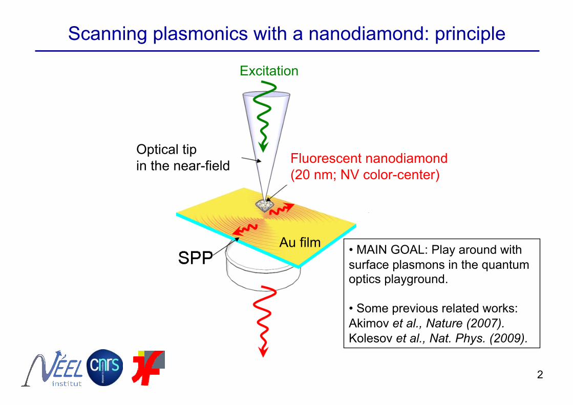
Scanning plasmonics with a nanodiamond: principle
Excitation
Fluorescent nanodiamond (20 nm; NV color-center)
Optical tip in the near-field
Au film • MAIN GOAL: Play around with surface plasmons in the quantum optics playground.
• Some previous related works: Akimov et al., Nature (2007). Kolesov et al., Nat. Phys. (2009).
3
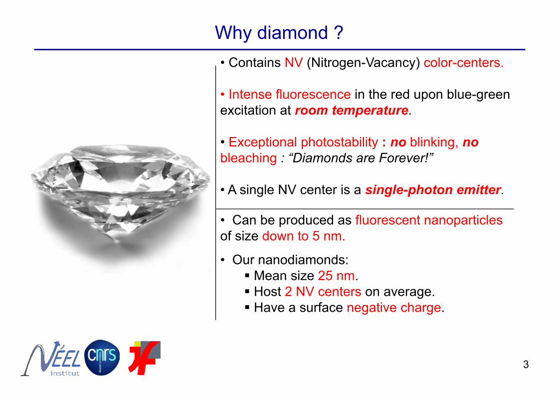
Why diamond ? • Contains NV (Nitrogen-Vacancy) color-centers.
• Intense fluorescence in the red upon blue-green excitation at room temperature.
• Exceptional photostability : no blinking, no bleaching : “Diamonds are Forever!”
• A single NV center is a single-photon emitter.
• Can be produced as fluorescent nanoparticles of size down to 5 nm.
• Our nanodiamonds: Mean size 25 nm. Host 2 NV centers on average. Have a surface negative charge.
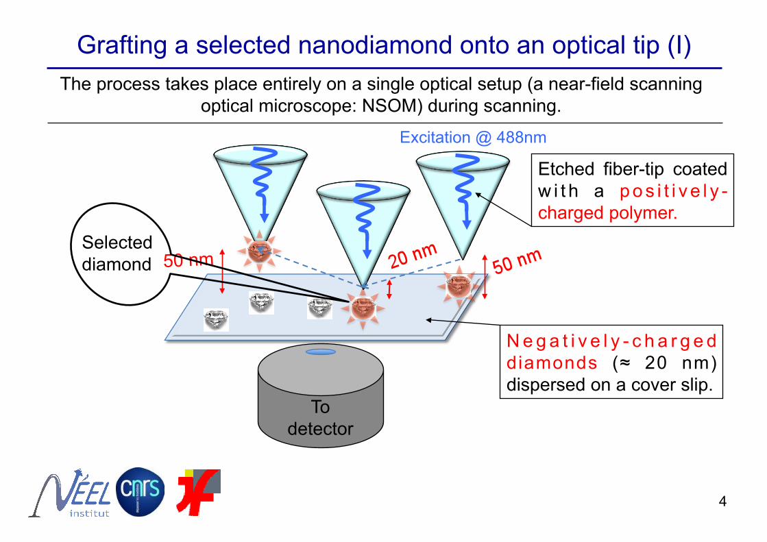
Grafting a selected nanodiamond onto an optical tip (I) The process takes place entirely on a single optical setup (a near-field scanning
optical microscope: NSOM) during scanning.
Etched fiber-tip coated w i t h a p o s i t i v e l y -charged polymer.
To detector
Selected diamond
N e g a t i v e l y - c h a r g e d diamonds (≈ 20 nm) dispersed on a cover slip.
Excitation @ 488nm
50 nm
4
5
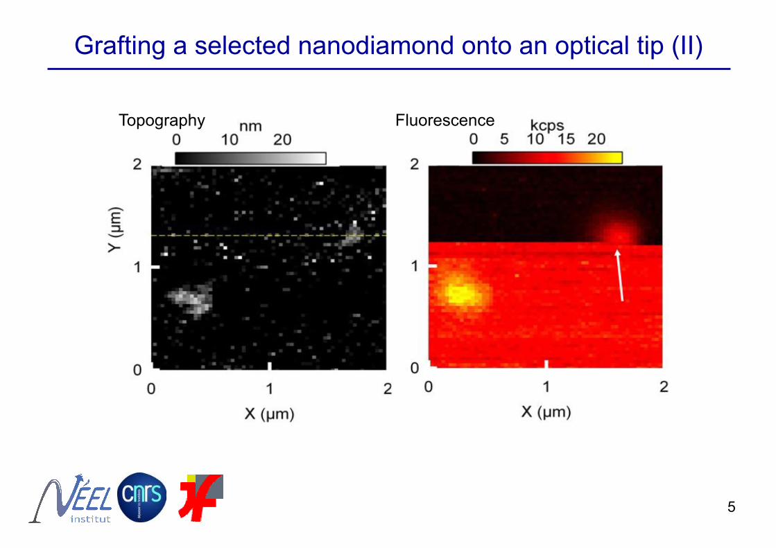
Grafting a selected nanodiamond onto an optical tip (II)
Topography Fluorescence
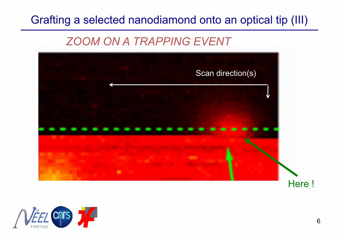
ZOOM ON A TRAPPING EVENT
Scan direction(s)
Here !
Grafting a selected nanodiamond onto an optical tip (III)
6

Photon-correlation single NV-center
The nanodiamond-based tip is a single-photon tip.
7
Characterization of the functionalized tip
g(2)
(τ)
0 delay τ (ns)
Y. Sonnefraud et al., Opt. Lett. 33, 611 (2008); A. Cuche et al., Opt. Express 17, 19969 (2009).
Spectrum neutral NV0 -center
ZPL
Reference spectrum
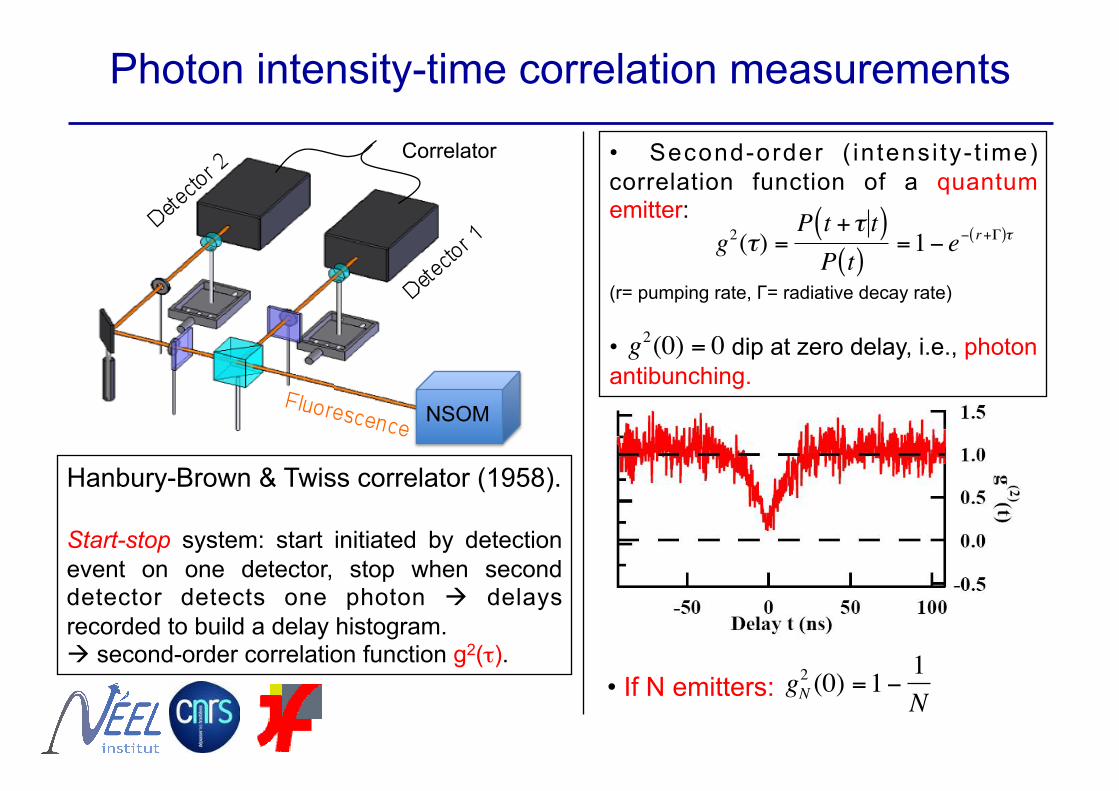
Photon intensity-time correlation measurements
Hanbury-Brown & Twiss correlator (1958).
Start-stop system: start initiated by detection event on one detector, stop when second detector detects one photon delays recorded to build a delay histogram. second-order correlation function g2(τ).
Correlator
€
g2(τ) =P t +τ t( )P t( )
=1− e− r+Γ( )τ
€
gN2 (0) =1− 1
N• If N emitters:
€
g2(0) = 0
NSOM
• Second-order ( in tensi ty- t ime) correlation function of a quantum emitter:
(r= pumping rate, Γ= radiative decay rate)
• dip at zero delay, i.e., photon antibunching.
Delay τ (ns)
2
1
0
Y(µm
)
210 X (µm)
50403020100Topographie (nm)
210
40302010Optique (kcps)
1.5
1.0
0.5
0.0
-0.5
g (2)(t)
100500-50Retard t (ns)
160
140
120
100
80
60
40
20
0
C(t)
Diagramme de corrélation
2
1
0
Y(µm
)
210 X (µm)
50403020100Topographie (nm)
210
40302010Optique (kcps)
1.5
1.0
0.5
0.0
-0.5
g (2)(t)
100500-50Retard t (ns)
160
140
120
100
80
60
40
20
0
C(t)
Diagramme de corrélation
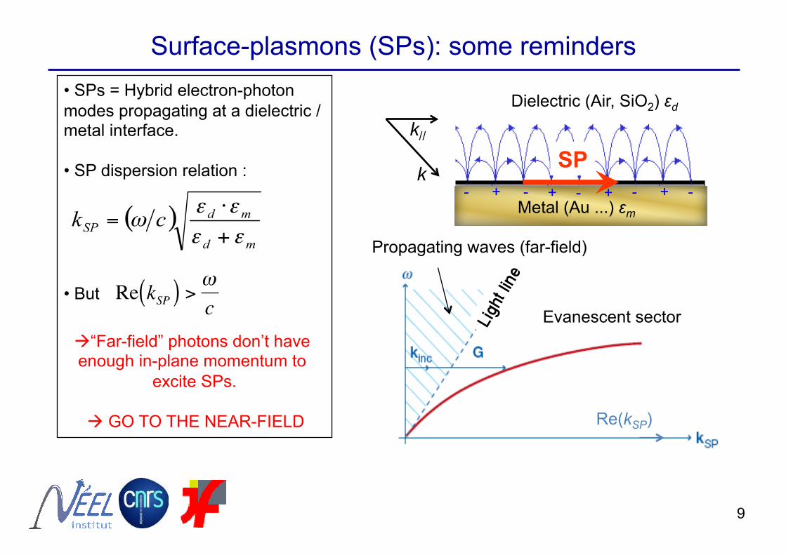
• SPs = Hybrid electron-photon modes propagating at a dielectric /metal interface.
• SP dispersion relation :
• But
“Far-field” photons don’t have enough in-plane momentum to
excite SPs.
GO TO THE NEAR-FIELD
Surface-plasmons (SPs): some reminders
€
Re kSP( ) >ωc
9
k// SP Au/Air
kmissing
Dielectric (Air, SiO2) εd
k//
k SP
+ + + +- - - - - Metal (Au ...) εm
Evanescent sector
Re(kSP)
Propagating waves (far-field)
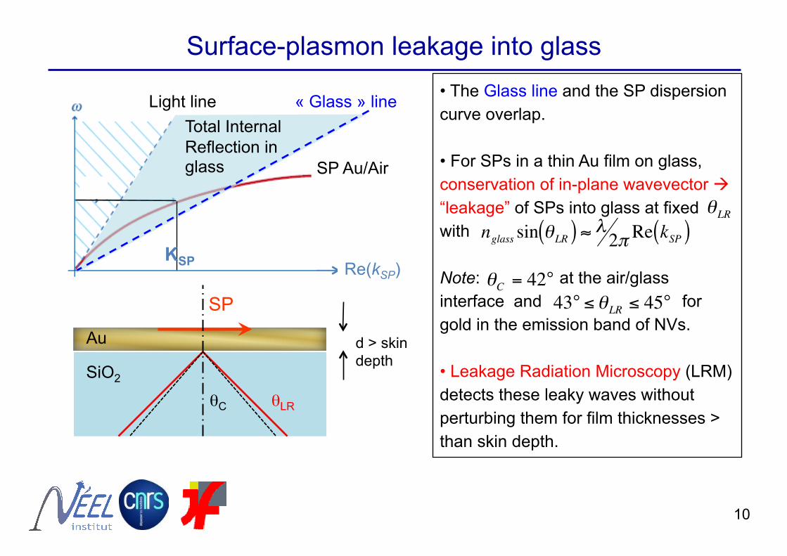
• The Glass line and the SP dispersion curve overlap.
• For SPs in a thin Au film on glass, conservation of in-plane wavevector “leakage” of SPs into glass at fixed with
Note: at the air/glass interface and for gold in the emission band of NVs.
• Leakage Radiation Microscopy (LRM) detects these leaky waves without perturbing them for film thicknesses > than skin depth.
€
nglass sin θLR( ) ≈ λ2π Re kSP( )
€
θLR
Light line
Re(kSP)
Surface-plasmon leakage into glass
« Glass » line
SP Au/Air
KSP
Total Internal Reflection in glass
€
θC = 42°
€
43° ≤θLR ≤ 45°
10
SP
SiO2
Au
θC θLR
d > skin depth
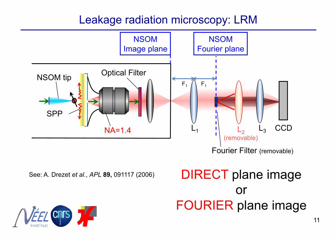
Fourier Filter (removable)
L1
NSOM tip
NA=1.4
Optical Filter
L3 CCD
SPP
NSOM Fourier plane
NSOM Image plane
F1 F1
Leakage radiation microscopy: LRM
DIRECT plane image or
FOURIER plane image
L2 (removable)
See: A. Drezet et al., APL 89, 091117 (2006)
11
12
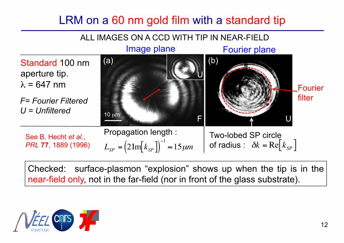
LRM on a 60 nm gold film with a standard tip ALL IMAGES ON A CCD WITH TIP IN NEAR-FIELD
Standard 100 nm aperture tip. λ = 647 nm
F= Fourier Filtered U = Unfiltered
(a) (b) Image plane Fourier plane
10 µm F
U
U
Checked: surface-plasmon “explosion” shows up when the tip is in the near-field only, not in the far-field (nor in front of the glass substrate).
Two-lobed SP circle of radius :
€
δk = Re kSP[ ]
Fourier filter
Propagation length :
€
LSP = 2Im kSP[ ]( )−1≈15µm
See B. Hecht et al., PRL 77, 1889 (1996)
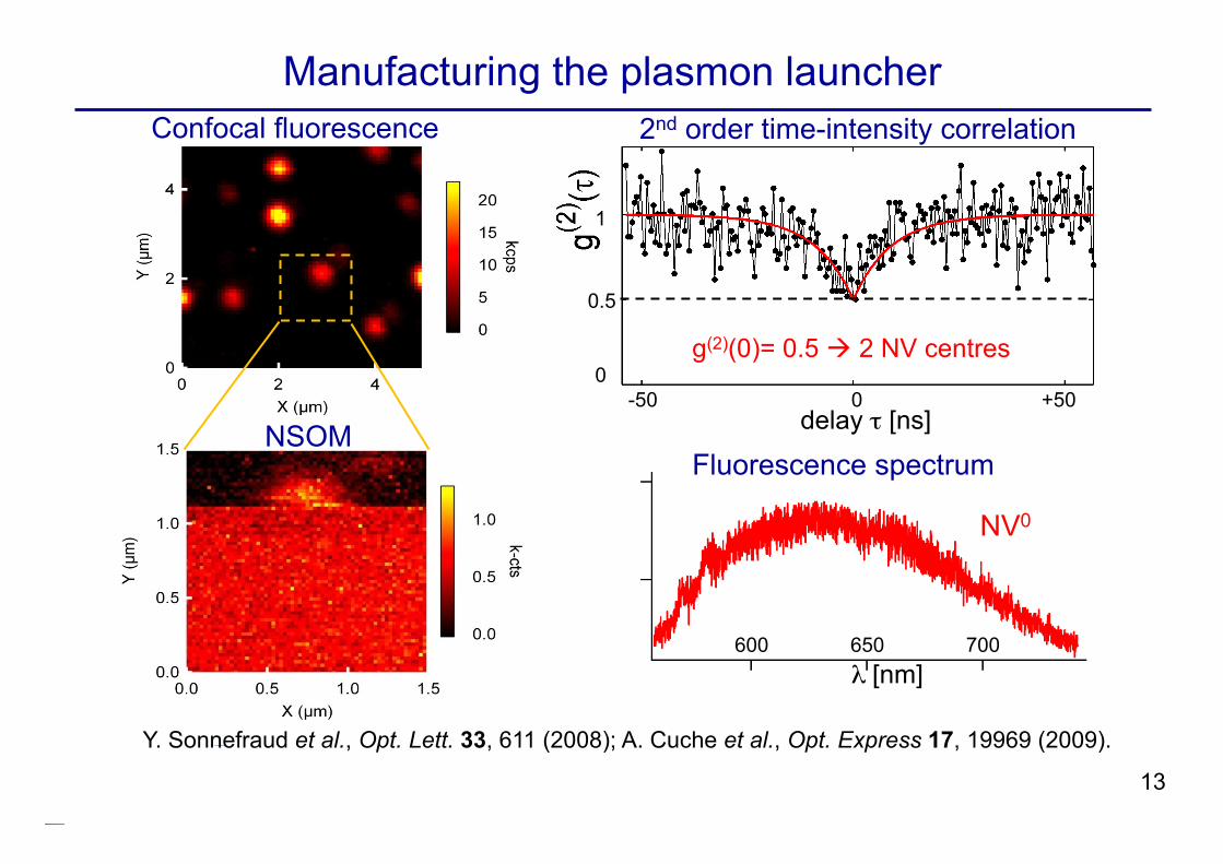
Confocal fluorescence
NSOM delay τ [ns] -50 +50 0
0
0.5
1
g(2)(0)= 0.5 2 NV centres
13
Y. Sonnefraud et al., Opt. Lett. 33, 611 (2008); A. Cuche et al., Opt. Express 17, 19969 (2009).
Manufacturing the plasmon launcher 2nd order time-intensity correlation
600 650 700 λ [nm]
NV0
Fluorescence spectrum
14
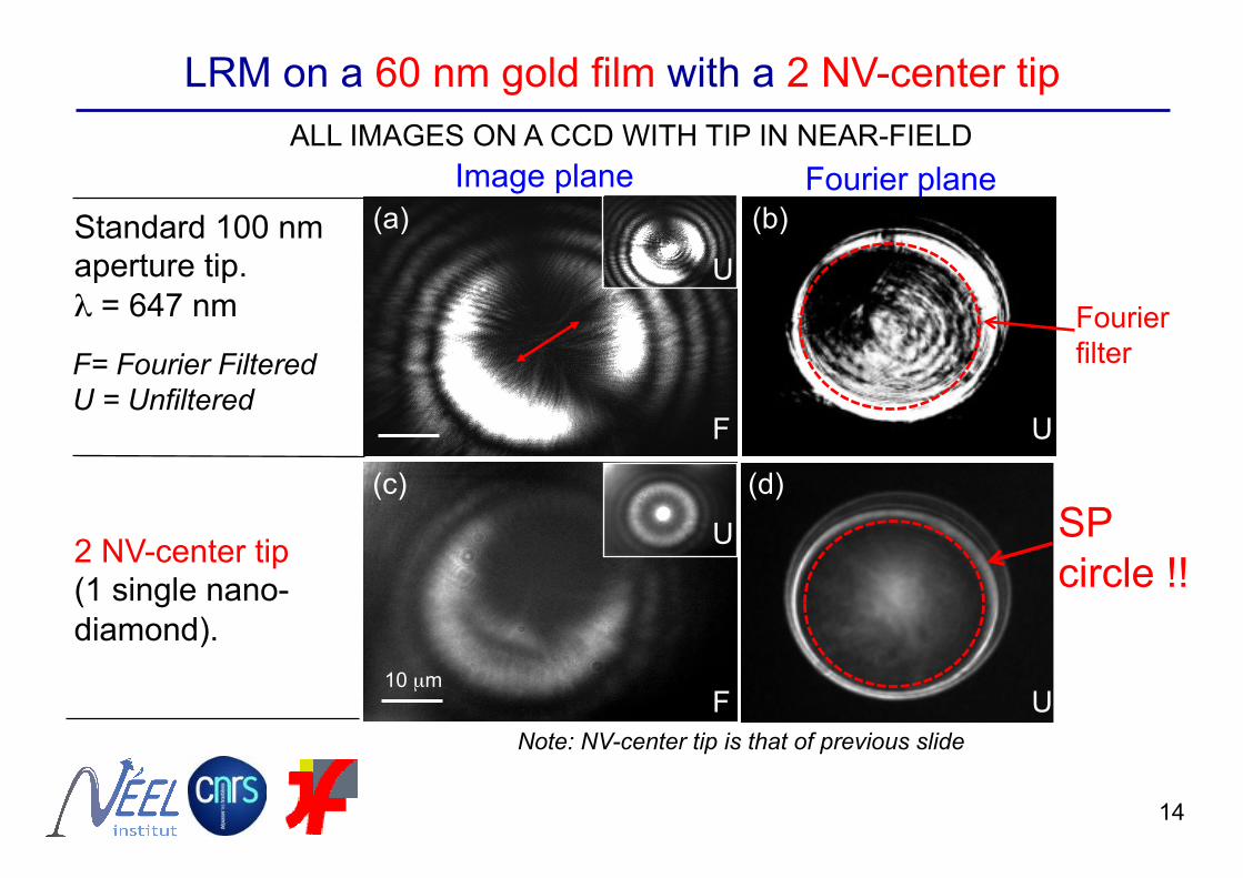
LRM on a 60 nm gold film with a 2 NV-center tip ALL IMAGES ON A CCD WITH TIP IN NEAR-FIELD
(c) (d)
2 NV-center tip (1 single nano-diamond).
F
U
U10 µm
Image plane Fourier plane
10 µm F
U
U
Standard 100 nm aperture tip. λ = 647 nm
F= Fourier Filtered U = Unfiltered
(a) (b)
SP circle !!
Note: NV-center tip is that of previous slide
UFourier filter
UF
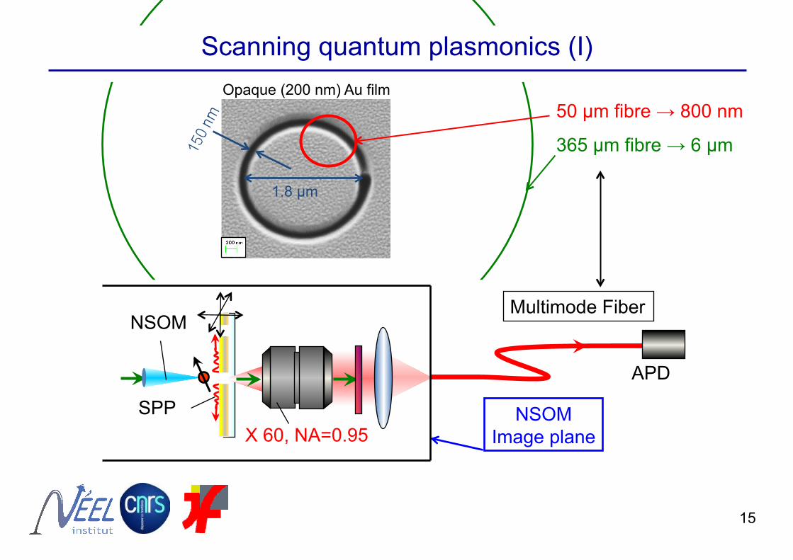
1.8 µm
Opaque (200 nm) Au film 50 µm fibre → 800 nm
365 µm fibre → 6 µm
Scanning quantum plasmonics (I)
NSOM
X 60, NA=0.95 SPP
APD
Multimode Fiber
NSOM Image plane
15
50 µm fibre
365 µm fibre
Simulation
16
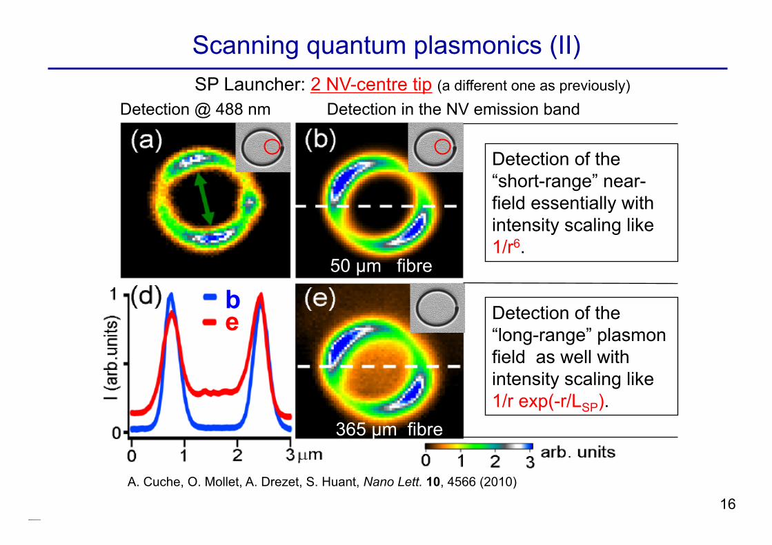
Scanning quantum plasmonics (II) SP Launcher: 2 NV-centre tip (a different one as previously)
Detection @ 488 nm Detection in the NV emission band
Detection of the “short-range” near-field essentially with intensity scaling like 1/r6.
Detection of the “long-range” plasmon field as well with intensity scaling like 1/r exp(-r/LSP).
be
A. Cuche, O. Mollet, A. Drezet, S. Huant, Nano Lett. 10, 4566 (2010)
17
Summary
We have grafted single nanodiamonds hosting two NV centers onto the apex of optical tips for the purpose of :
“DETERMINISTIC“ LAUNCHING OF SINGLE SURFACE PLASMONS
INTO GOLD FILM (at most two at any time).
This is a successful step into
“DETERMINISTIC” QUANTUM PLASMONICS.
THANKS TO:
• Aurélien Cuche, Oriane Mollet, Aurélien Drezet (Néel Institute).
• Jean-François Roch, François Treussart (LPQM, ENS Cachan).
• J.-P. Boudou (LMSSMat, Centrale Paris) & T. Sauvage (CEMHTI, Orléans).
• Yannick Sonnefraud (Imperial College, London).
€€€€€: ANR Projects NAPHO and PlasTips, Région Rhône-Alpes
THANK YOU FOR YOUR ATTENTION !
18