plasmonics for future biosensors - web.uvic.caagbrolo/nphoton.2012.266.pdf · plasmonics for future...
TRANSCRIPT
© 2012 Macmillan Publishers Limited. All rights reserved.
NATURE PHOTONICS | VOL 6 | NOVEMBER 2012 | www.nature.com/naturephotonics 709
FOCUS | COMMENTARY
Plasmonics for future biosensorsAlexandre G. Brolo
Confinement and enhancement of light by plasmonics allows a high density of independent subwavelength sensor elements to be constructed in micrometre-sized arrays. It is relatively straightforward to integrate those sensors into microfluidics chips, making plasmonic structures promising for use in next-generation modern biosensors.
Low-cost biosensors, designed for fast, real-time identification of biomarkers, are required in several new healthcare
programmes, including routine point-of-care (POC) clinical evaluation, real-time diagnosis of diseases in developing countries and fast genetic mapping for personalized care. The next generation of biomedical devices will ideally be miniaturized and automated. Commercial glucose sensors provide a benchmark for the basic requirements, with the caveat that future biosensors will need to quantify not one, but several, species of interest at the same time, that is, multiplex detection. The vision of a new generation of biomedical devices for personal monitoring and POC applications has driven several advances in the field of microelectromechanical systems (MEMS), particularly in terms of fluid manipulation in micrometre-sized channels (microfluidics), automated chemical and biochemical operations (lab-on-a-chip), and optofluidics integration1. Plasmonic materials typically consist of metallic structures that support electromagnetic oscillations known as surface plasmon polaritons at their interfaces. Resonant excitations of these optical fields, that is, surface plasmon resonances (SPRs), are very sensitivity to the dielectric materials in contact with the metallic surface. SPRs in the visible/near-infrared wavelength range are of particular interest because there is favourable optical confinement at these wavelengths, and may become a major component in the next generation of biosensors2.
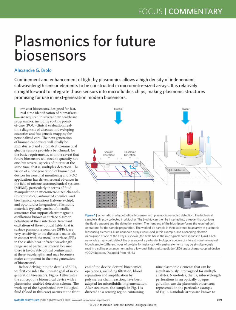
Before delving into the details of SPRs, we first consider the ultimate goal of next-generation biosensors. Figure 1 illustrates the concept of a biomedical device with a plasmonics-enabled detection scheme. The work-up of the hypothetical raw biological fluid (blood in this case) occurs at the front
end of the device. Several biochemical operations, including filtration, blood separation and amplification by polymerase chain reaction, have been adapted for microfluidic implementation. After treatment, the sample in Fig. 1 is directed to a sensing region containing
nine plasmonic elements that can be simultaneously interrogated for multiple analytes. Nanoholes, that is, subwavelength perforations in an optically opaque gold film, are the plasmonic biosensors represented in the particular example of Fig. 1. Nanohole arrays are known to
Figure 1 | Schematic of a hypothetical biosensor with plasmonics-enabled detection. The biological sample is directly collected in a biochip. The biochip can then be inserted into a reader that contains the fluidic support and the detection system. The front end of the biochip performs the required unit operations for the sample preparation. The worked-up sample is then delivered to an array of plasmonic biosensing elements. Nine nanohole arrays were used in this example, and a scanning electron micrograph of one of the arrays is shown (the scale bar in the micrograph corresponds to 1 μm). Each nanohole array would detect the presence of a particular biological species of interest from the original blood sample (different types of protein, for instance). All sensing elements may be simultaneously read in a collinear arrangement using a low-cost light-emitting diode (LED) and a charge-coupled device (CCD) detector. (Adapted from ref. 4.)
Biochip Reader
SampleTreatment
PlasmonicDetection
CCD detector
LED
© 2012 Macmillan Publishers Limited. All rights reserved.
710 NATURE PHOTONICS | VOL 6 | NOVEMBER 2012 | www.nature.com/naturephotonics
COMMENTARY | FOCUS
support enhanced light transmission at wavelengths that sustain surface plasmon excitations3. Using such arrays, the excitation and detection of SPRs can be realized in a collinear arrangement using a low-cost light-emitting diode and a camera. The small footprint of the plasmonic sensor array allows the biochemical characterization of the sample from a very small volume (<10 μl) of the initial biological material. The advantages of such devices justify the large amount of activity in the area of plasmonic biosensing, and the example in Fig. 1 indicates how other nanostructures might have a key role in future healthcare applications.
Basic concepts, sensor performance and the state of the artSurface plasmons can exist when conduction electrons near the surface of a metallic nanostructure undergo concerted oscillations coupled to an external optical field and, in addition, certain existence conditions are satisfied. The light is slowed down and confined to the surface as a
result of the coupling to the electrons. This can result in subwavelength light confinement and enhancement near the metallic surface, which is central to the development of new concepts in the fields of nano-optics and metamaterials4,5. Another important consequence of the enhanced localized SPR fields is the increase in the emission and scattering signals of molecules adsorbed on those nanostructures, which can be by several orders of magnitude. These enhancements in signal are respectively known as the surface-enhanced fluorescence effect6 and the surface-enhanced Raman scattering effect7. Although both effects can be used for biosensing, we restrict the present discussion to plasmonics-based refractometric sensors.
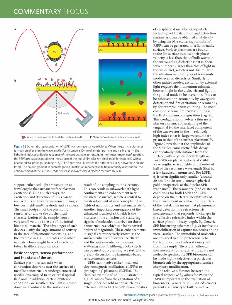
SPRs can involve either ‘localized’ electromagnetic oscillations (LSPRs) or ‘propagating’ plasmons (PSPRs). The classical example of LSPR, illustrated in Fig. 2a, arises from the excitation of a single spherical gold nanoparticle by an external light field. The SPR characteristics
of an spherical metallic nanoparticle, including field distribution and extinction parameters, can be obtained analytically by using the Mie scattering formalism8. PSPRs can be generated on a flat metallic surface. Surface plasmons are bound to the flat surface because their phase velocity is less than that of bulk waves in the surrounding dielectric (that is, their wavenumber is larger than that of light in the dielectric), which is not dissimilar to the situation in other types of waveguide mode, even in dielectrics. Similarly to other guided modes, excitation by external light requires the momentum mismatch between light in the dielectric and light in the guided mode to be overcome. This can be achieved non-resonantly by waveguide defects or end-fire excitation, or resonantly by, for example, prism coupling. The most common scheme for prism coupling is the Kretschmann configuration (Fig. 2b). This configuration involves a thin metal film on a prism, and matching of the tangential (to the interface) component of the wavevector in the — relatively high index (that is, large wavenumber) — prism to that of the surface plasmons9,10. Figure 2 reveals that the amplitudes of the SPR electromagnetic fields decay exponentially with distance from the surface, with a typical decay length δd. For PSPR on planar surfaces at visible wavelengths, δd is roughly of the order of half of the resonance wavelength (that is, a few hundred nanometres). For LSPR, δd is often significantly smaller (around 20 nm for a 30-nm-diameter spherical gold nanoparticle at the dipolar SPR resonance9). The resonance (and existence) conditions for both LSPR and PSPR depend on the dielectric permittivity of the environment in contact to the surface of the metal. This means that plasmonics-based detection is a refractometric measurement that responds to changes in the effective refractive index within the surface plasmon decay length, δd. Generic SPR biosensing schemes (Fig. 2) involve the immobilization of capture molecules on the metal surface. The immobilized molecules are designed to bind preferentially to the biomolecules of interest (analytes) from the sample. Therefore, although measurements of refractive index are not molecule specific, the SPR biosensor can be made highly selective to a particular biomolecule by the appropriated surface chemistry modification.
The relative difference between the typical respective δd values for PSPR and LSPR is important in the evaluation of biosensors. Generally, LSPR-based sensors present a sensitivity to bulk refractive
Figure 2 | Schematic representation of LSPR from a single nanoparticle. a, When the particle diameter is much smaller than the wavelength (for instance a 10-nm-diameter particle and visible light), the light field induces a dipolar response of the conducting electrons. b, In the Kretschmann configuration, the PSPR propagates parallel to the surface of the metal film (50-nm-thick gold, for instance) with a characteristic propagation length, δSP. The figure also illustrates the differences in δd between LSPR and PSPR. The colour gradient in each magnified illustration represents the field intensity distribution (the enhanced field at the surface (red) decreases towards the dielectric medium (blue)).
Au
SPR angle
Lase
r
Detecto
r
a
b
Au
Au
Analyte (biomolecule to be detected/quantified) “Capture”molecule (surface immobilized)
δd
δdAuδSP
© 2012 Macmillan Publishers Limited. All rights reserved.
NATURE PHOTONICS | VOL 6 | NOVEMBER 2012 | www.nature.com/naturephotonics 711
FOCUS | COMMENTARY
index changes that is at least an order of magnitude smaller than that of sensors based on PSPR. However, the smaller δd values in the case of LSPR mean that those types of sensor respond better to changes closer to the surface, as required for biosensing. In fact, the performance of nanoparticle-based LSPR and that of Kretschmann-based PSPR have been shown to be equivalent for monitoring protein adsorption11. The surface plasmon field is spatially confined to the region around the subwavelength particle in the LSPR case (Fig. 2a), but the surface wave propagates parallel to the metallic surface in the PSPR case (Fig. 2b). This
surface propagation allows application of plasmonic materials as subwavelength waveguides that can be incorporated into different types of nanophotonics design and circuit12. Typically, the PSPR propagation length, δSP, ranges from a few to hundreds of micrometres, depending on the excitation wavelength; but it can even reach millimetres, or longer, for the special case of long-range SPR13,14. There is no propagation length to define in the LSPR case, although here we can consider the plasmon lifetime, which is determined by loss (and is proportional to the propagation length in the case of PSPRs). In plasmonic biosensing, the δSP value provides a lower
limit on the size of the sensor element. At the same time, very small propagation lengths (or lifetimes) are not necessarily desirable because they imply large dissipation and broader resonances, which negatively affect the performance of the device in sensing applications. However, mirrors, such as Bragg reflectors, can be designed to contain the lower-loss, longer-propagation SPRs, allowing dense integration of sensitive biosensors15.
At present, the range of available plasmonics-based biosensors is dominated by instruments that operate using the Kretschmann arrangement (Fig. 2b). Although miniaturized versions of Kretschmann-based SPR have been commercialized, the high-end instrumentation is bulky and not suitable for POC applications. The physical size of the sensing element is limited by the δSP value, and the reflection geometry of the prism coupling scheme adds limitations for multiplex detection in imaging mode. In summary, commercial SPR systems present some important limitations which motivate the search for types of plasmonic structure that are more suitable for both imaging and lab-on-a-chip integration. The commercially available SPR instruments also provide performance benchmarks that guide the development of new plasmonics-based platforms. There have been several recent reports of novel plasmonic sensors that rival the performance of the commercial systems while offering other advantages, such as low-cost mass production16. Fano resonances arise in the plasmonic context from the coherent interference between evanescent (dark) and propagating (bright) modes17. They are characterized by a higher sensitivity to changes in refractive index and a narrow linewidth (dictated by the intrinsic lifetime of the dark mode). Fano modes explored in arrays of nanoholes in gold films have performed better as biosensors than has Kretschmann-based SPR18. The performance of a plasmonic sensor can be further enhanced by combining the SPR with other types of guided mode (hybrid sensors). For instance, in a metamaterial array of silver nanorods capable of supporting a guided mode, the interaction between the guided mode and the SPR between the closely spaced nanorods led to excellent sensor performance in the near-infrared19 (1,230 nm).
Single-particle, single-nanohole and single-molecule sensingSingle metallic nanoparticles or single nanometric holes in metal films constitute some of the simplest plasmonic platforms.
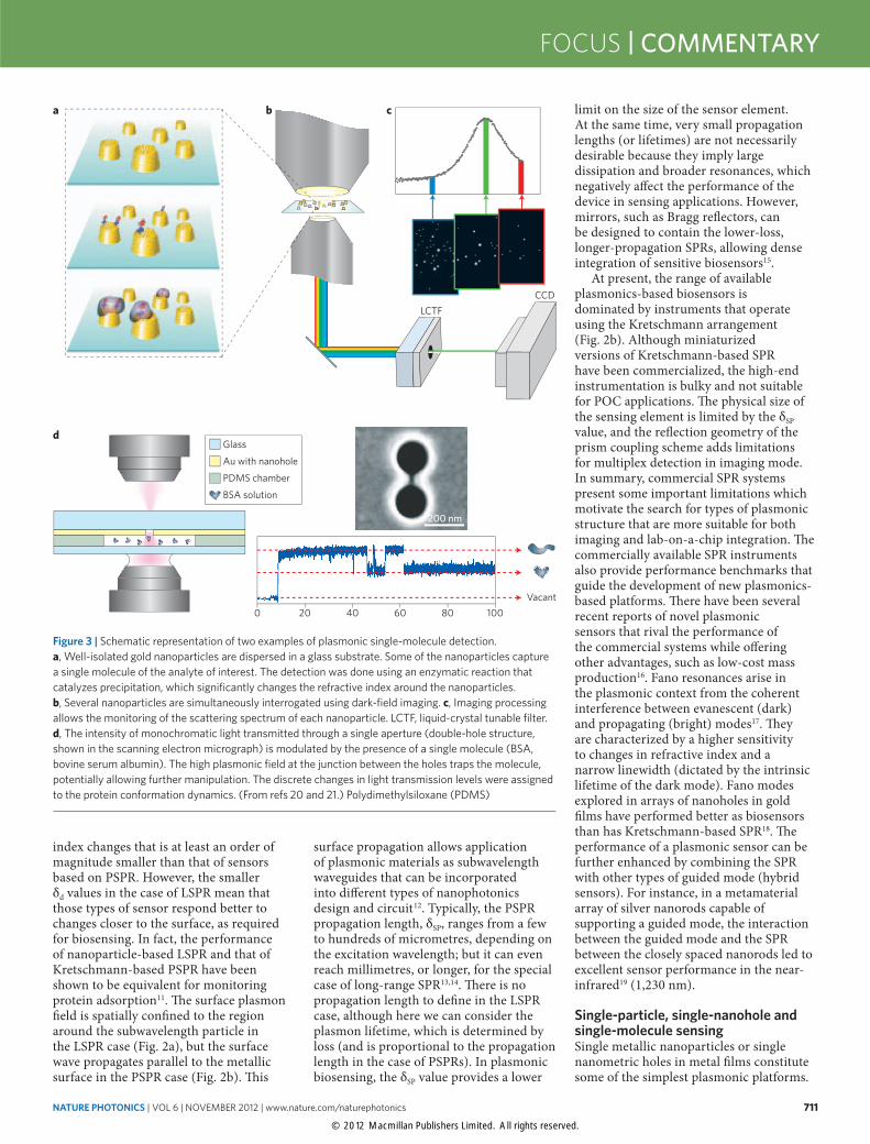
Figure 3 | Schematic representation of two examples of plasmonic single-molecule detection. a, Well-isolated gold nanoparticles are dispersed in a glass substrate. Some of the nanoparticles capture a single molecule of the analyte of interest. The detection was done using an enzymatic reaction that catalyzes precipitation, which significantly changes the refractive index around the nanoparticles. b, Several nanoparticles are simultaneously interrogated using dark-field imaging. c, Imaging processing allows the monitoring of the scattering spectrum of each nanoparticle. LCTF, liquid-crystal tunable filter. d, The intensity of monochromatic light transmitted through a single aperture (double-hole structure, shown in the scanning electron micrograph) is modulated by the presence of a single molecule (BSA, bovine serum albumin). The high plasmonic field at the junction between the holes traps the molecule, potentially allowing further manipulation. The discrete changes in light transmission levels were assigned to the protein conformation dynamics. (From refs 20 and 21.) Polydimethylsiloxane (PDMS)
d
LCTFCCD
0 20 40 60 80 100
Glass
Au with nanohole
PDMS chamber
BSA solution
Vacant
200 nm
a b c
© 2012 Macmillan Publishers Limited. All rights reserved.
712 NATURE PHOTONICS | VOL 6 | NOVEMBER 2012 | www.nature.com/naturephotonics
COMMENTARY | FOCUS
They well illustrate the potential of plasmonics to generate high-density arrays of sensors with high performance20–22 (Fig. 3). In Fig. 3a, the isolated nanoparticles (60 nm in diameter), which are immobilized in a solid support, each behaves as a sensor element, providing a spatial limit to plasmonic biosensors that is mainly restricted by diffraction effects inherent to far-field optical arrangements. The full scattering spectrum is easily obtained from individual particles, owing to their large scattering cross-section. The high surface sensitivity of LSPR from single nanoparticles has been explored in the example of Fig. 3 to monitor single-molecule chemical events. Enhanced single-molecule sensitivity was achieved by using an enzymatic reaction, as in an ordinary enzyme-linked immunosorbent assay. A label-free, single-molecule bioaffinity assay with single particles using a photothermal detection scheme has also been reported23. The single-molecule detection limit can also be achieved using nano-apertures in metal films (Fig. 3d). Nano-apertures also allow the trapping and manipulation of single particles24 and single protein molecules21. The presence of a single molecule alters the optical transmission through the apertures, enabling this platform to follow molecular dynamics, such as conformational changes in proteins21. The combined single-particle and single-molecule capabilities of LSPR
offer a small sensing volume and the ultimate limit of detection. These attributes, allied to the possibility of single-molecule manipulation of plasmonic trapping, well illustrate the potential for plasmonic implementation in applications that require massive multiplexing.
Hotspots and plasmonic–fluidic integrationHotspots (special regions with high electromagnetic field intensities) are always present in plasmonic structures owing to the evanescent nature of the field distribution. Figure 2a illustrates this concept for a single metallic nanoparticle. Molecules adsorbed in hotspots experience stronger interaction and increased sensitivity25. The preferential chemical modification of the hotspots directs the analytes of interest to the most sensitive areas of the sensor26. This approach also significantly restricts the amount of (highly priced) biological material required for the surface modification. Single-particle, single-nanohole and selective hotspot patterning are sensing modalities that allow a low detection limit (in terms of the amount of adsorbed material) and they operate in very small sensing volumes (between 1 al (10−18 l) and 1 zl (10−21 l)). The small sensing volumes have an effect in the probability of capturing the molecule of interest. For instance, only about one molecule is present in an attolitre of 10 μM solution. The typical concentrations of analytes of interest in
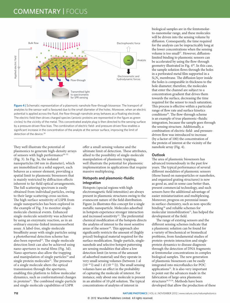
biological samples are in the femtomolar-to-nanomolar range, and these molecules will be driven into the sensing volume by diffusion. Consequently, the time required for the analysis can be impracticably long at the lower concentrations when the sensing volume is too small27. However, diffusion-limited binding to plasmonic sensors can be accelerated by using the flow-through geometry illustrated in Fig. 428. In this case, the sample solution flows through the holes in a perforated metal film supported in a Si3N4 membrane. The diffusion layer inside the holes is comparable in thickness to the hole diameter; therefore, the molecules that enter the channel are subject to a concentration gradient that drives them towards the surface, decreasing the time required for the sensor to reach saturation. This process is effective within a particular range of flow rate and surface kinetics conditions29. The flow-through scheme is an example of true plasmonic–fluidic integration, because the sample goes through the sensing structure. Additionally, a combination of electric-field- and pressure-driven flow was introduced to increase (by a factor of 100) the concentration of the protein of interest at the vicinity of the nanohole array (Fig. 4).
OutlookThe area of plasmonic biosensors has advanced tremendously in the past few years. The typical performance of several different modalities of plasmonic sensors (those based on nanoparticles or nanoholes, and organized grating structures) is now as good as, and in some case better than, present commercial technology, and such sensors have the additional advantage of easier miniaturization and multiplexing. Moreover, progress on perennial issues in surface chemistry, such as non-specific binding30 and reliable schemes for molecular immobilization31, has helped the development of the field.
The range of existing sensors and the different sensing schemes indicate that a plasmonic solution can be found for a variety of biochemical or biomedical problems, from fundamental studies of protein–protein interaction and single-protein dynamics to disease diagnosis through the detection of DNA fragments at femtomolar concentrations in complex biological samples. The new generation of plasmonic biosensors can be easily integrated into microfluidics for POC applications32. It is also very important to point out the advances made in the fabrication of large-area plasmonic structures16,33,34. Methods have been developed that allow the production of these
Flow-through
Bulk flow
App
lied
elec
tric
fiel
d
+
–Transmitted light to spectrometre for SPR sensing
– Analyte
Electrophoretic force
Electroosmotic andhydrodynamic forces
Figure 4 | Schematic representation of a plasmonic nanohole flow-through biosensor. The transport of analytes to the sensor wall is favoured due to the small diameter of the holes. Moreover, when an electric potential is applied across the fluid, the flow-through nanohole array behaves as a floating electrode. The electric field then drives charged species (anionic proteins are represented in the figure as green circles) to the vicinity of the metal. This concentrated analyte plug is then directed to the sensing surface by a pressure-driven flow bias. The combination of electric field- and pressure-driven flow enables a significant increase in the concentration of the analyte at the sensor surface, improving the limit of detection of the device.28
© 2012 Macmillan Publishers Limited. All rights reserved.
NATURE PHOTONICS | VOL 6 | NOVEMBER 2012 | www.nature.com/naturephotonics 713
FOCUS | COMMENTARY
nanostructures using low-cost substrates, such as plastics35 and polymers16.
As a central component in the field of nano-optics, one of the most exciting research areas in modern science, plasmonics will continue to evolve: faster, smaller and cheaper plasmonics-based sensor architectures will be reported in the years to come, capitalizing on recent breakthroughs such as nanohole flow-through, LSPR single-molecule detection and highly sensitive Fano resonances. One challenge for the field, however, is to translate those technologies into biomedical devices. Biosensors (and sensorial systems in general) will be ubiquitous in the near future, because they are required for the major transformative approaches that have been predicted, such as routine POC-based diagnosis and personalized medicine. Low-cost biosensors are also necessary in developing countries and remote locations for fast diagnosis of endemic diseases. Plasmonic biosensors are therefore well poised not only to be at the heart of an upcoming revolution in healthcare approaches, but to actually drive it. ❒
Alexandre G. Brolo is in the Department of Chemistry, University of Victoria, British Columbia V8W 3V6, Canada. e-mail: [email protected]
References1. Yeo, L. Y., Chang, H-C., Chan, P. P. Y. & Friend, J. R. Small 7,
12–48 (2011).2. Anker, J. N. et al. Nature Mater. 7, 442–453 (2008).3. Ebbesen, T. W., Lezec, H. J., Ghaemi, H. F., Thio, T. & Wolff, P. A.
Nature 391, 667–669 (1998).4. Fang, N., Lee, H., Sun, C. & Zhang, X. Science 308,
534–537 (2005).5. Bozhevolnyi, S. I., Volkov, V. S., Devaux, E., Laluet, J-Y. &
Ebbesen, T. W. Nature 440, 508–511 (2006).6. Russell, K. J., Liu, T-L., Cui, S. & Hu, E. L. Nature Photon. 6,
459–462 (2012).7. Fan, M., Andrade, G. F. S. & Brolo, A. G. Anal. Chim. Acta 693,
7–25 (2011).8. Kelly, K. L., Coronado, E., Zhao, L. L. & Schatz, G. C. J. Phys.
Chem. B 107, 668–677 (2003).9. Raether, H. Surface Plasmons on Smooth and Rough Surfaces and
on Gratings (Springer Tracts Mod. Phys. 111, Springer, 1988). 10. Kretschmann, E. & Raether, H. Z. Naturforsch. A 23,
2135–2136 (1968).11. Otte, M. A., Sepúlveda, B., Ni, W., Juste, J. P., Liz-Marzán, L. M. &
Lechuga, L. M. ACS Nano 4, 349–357 (2010).12. Gramotnev, D. K. & Bozhevolnyi, S. Nature Photon. 4, 83–91 (2010).13. Berini, P., Charbonneau, R., Lahoud, N. & Mattiussi, G. J. Appl.
Phys. 98, 043109 (2005).14. Fukui, M., So, V. C. Y. & Normandin, R. Phys. Status Solidi 91,
K61–K64 (1980).15. Lindquist, N. C., Lesuffleur, A., Im, H. & Oh, S. H. Lab Chip 9,
382–387 (2009).
16. Gao, H. et al. Nano Lett. 10, 2549–2554 (2010).17. Lukyanchuk, B. et al. Nature Mater. 9, 707–715 (2010).18. Yanik, A. A. et al. Proc. Natl Acad. Sci. USA 108,
11784–11789 (2011).19. Kabashin, A. V. et al. Nature Mater. 8, 867–871 (2009).20. Chen, S., Svedendahl, M., Van Duyne, R. P. & Kall, M. Nano Lett.
11, 1826–1830 (2011).21. Ament, I., Prasad, J., Henkel, A., Schmachtel, S. & Sonnichsen, C.
Nano Lett. 12, 1092–1095 (2012).22. Pang, Y. & Gordon, R. Nano Lett. 12, 402–406 (2012).23. Zijlstra, P., Paulo, P. M. R. & Orrit, M. Nature Nanotech. 7,
379–382 (2012).24. Juan, M. L., Gordon, R., Pang, Y., Eftekhari, F. & Quidant, R.
Nature Phys. 5, 915–919 (2009).25. Beeram, S. R. & Zamborini, F. P. J. Am. Chem. Soc. 131, 11689–
11691 (2009).26. Feuz, L., Jonsson, P., Jonsson, M. P. & Hook, F. ACS Nano 4,
2167–2177 (2010).27. Sheehan, P. E. & Whitman, L. J. Nano Lett. 5,
803–807 (2005).28. Escobedo, C., Brolo, A. G., Gordon, R. & Sinton, D. Nano Lett. 12,
1592–1596 (2012).29. Escobedo, C., Brolo, A. G., Gordon, R. & Sinton, D. Anal. Chem.
82, 10015–10020 (2010).30. Bolduc, O. R., Pelletier, J. N. & Masson, J-F. Anal. Chem. 82,
3699–3706 (2010).31. Wittenberg, N. J. et al. Anal. Chem. 84, 6031–6039 (2012).32. Kim, J. Lab Chip 12, 3611–3623 (2012).33. Nagpal, P., Lindquist, N. C., Oh, S. H. & Norris, D. J. Science 325,
594–597 (2009).34. Menezes, J. W., Ferreira, J., Santos, M. J. L., Cescato, L. & Brolo, A.
G. Adv. Funct. Mater. 20, 3918–3924 (2010).35. Fan, M., Andrade, M. L., Thompson, M. & Brolo, A. G. Anal.
Chem. 82, 6350–6352 (2010).