towards 4g - ieee global communications conference
TRANSCRIPT

Towards 4G : Technical Overview of LTE and LTE-Advanced
IEEE GLOBECOM 2011 2011.12.09 Dr. Hyung G. Myung, Qualcomm

Outline
1
Wireless Background
Summary and References
Long Term Evolution (LTE)
LTE-Advanced
4G Enabling Technologies

Wireless Background
• Fundamental limits
• Multiple access schemes
• Broadband wireless channel basics
• Cellular system
2

Fundamental Constraints
• Shannon’s capacity upper bound – Achievable data rate is fundamentally limited by bandwidth and signal
-to-noise ratio (SNR).
3
2log 1 [bits per second]S
C BWN
Signal power
Noise power Channel bandwidth

Wider Bandwidth
• Demand for higher data rate is leading to utilization of wider transmission bandwidth.
4
GSM IS-95 UMTS/WCDMA LTE LTE-Advanced
200 kHz 1.25 MHz 5 MHz
20 MHz
100 MHz

Challenges of Wireless Communications
• Multipath radio propagation
• Spectrum limitations
• Limited energy
• User mobility
• Resource management
5

Duplexing
• Two ways to duplex downlink (base station to mobile) and uplink (mobile to base station) – Frequency division duplexing (FDD)
– Time division duplexing (TDD)
6
Downlink (Forward link)
Uplink (Reverse link)
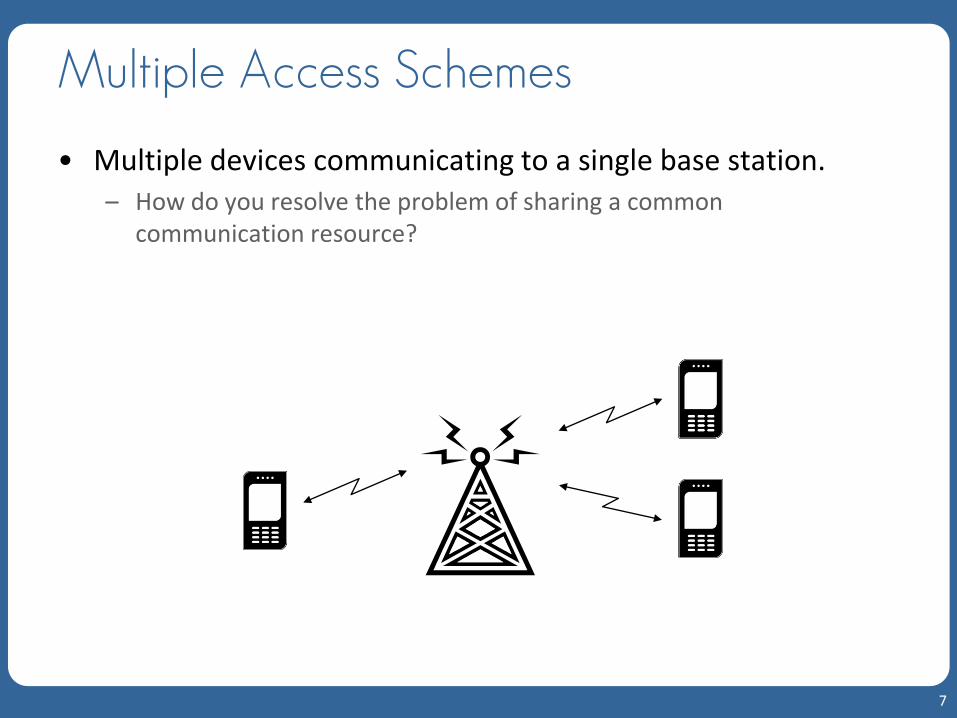
Multiple Access Schemes
• Multiple devices communicating to a single base station. – How do you resolve the problem of sharing a common
communication resource?
7

Multiple Access Schemes
• Access resources can be shared in time, frequency, code, and space. – Time division multiple access (TDMA): GSM
– Frequency division multiple access (FDMA): AMPS
– Code division multiple access (CDMA): IS-95, UMTS
– Spatial division multiple access (SDMA): iBurst
8
- cont.

Wireless Channel
• Wireless channel experiences multi-path radio propagation.
9

Multipath Radio Propagation
10
- cont.
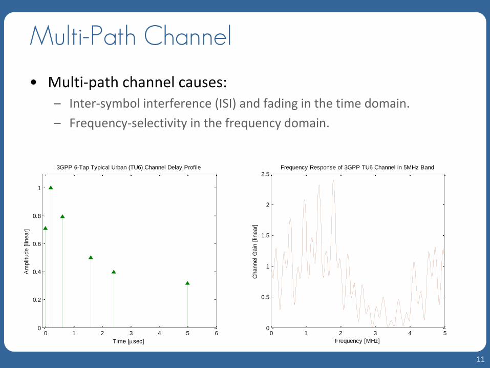
Multi-Path Channel
• Multi-path channel causes: – Inter-symbol interference (ISI) and fading in the time domain.
– Frequency-selectivity in the frequency domain.
11
0 1 2 3 4 5 60
0.2
0.4
0.6
0.8
1
Time [sec]
Am
plit
ude [
linear]
3GPP 6-Tap Typical Urban (TU6) Channel Delay Profile
0 1 2 3 4 50
0.5
1
1.5
2
2.5
Frequency [MHz]
Channel G
ain
[lin
ear]
Frequency Response of 3GPP TU6 Channel in 5MHz Band

Multi-Path Channel
• For broadband wireless channel, ISI and frequency-selectivity become severe.
• To resolve the ISI and the frequency-selectivity in the channel, various measures are used. – Channel equalization in the time domain or frequency domain
– Multi-carrier multiplexing
• Orthogonal frequency division multiplexing (OFDM)
– Frequency hopping
– Channel-adaptive scheduling
– Channel coding
– Automatic repeat request (ARQ) and hybrid ARQ (H-ARQ)
12
- cont.

Mobile User
• When the user is mobile, the channel becomes time-varying.
• There is also Doppler shift in the carrier frequency.
13

Time-Varying Multi-path Channel
14
0
1
2
3
4
5
0
1
2
3
4
5
0
5
Time [msec]
Mobile speed = 60 km/h (111 Hz doppler)
Frequency [MHz]
Channel G
ain
[lin
ear]
0
1
2
3
4
5
0
1
2
3
4
5
0
5
Time [msec]
Mobile speed = 3 km/h (5.6 Hz doppler)
Frequency [MHz]
Channel G
ain
[lin
ear]

Wireless Spectrum
15
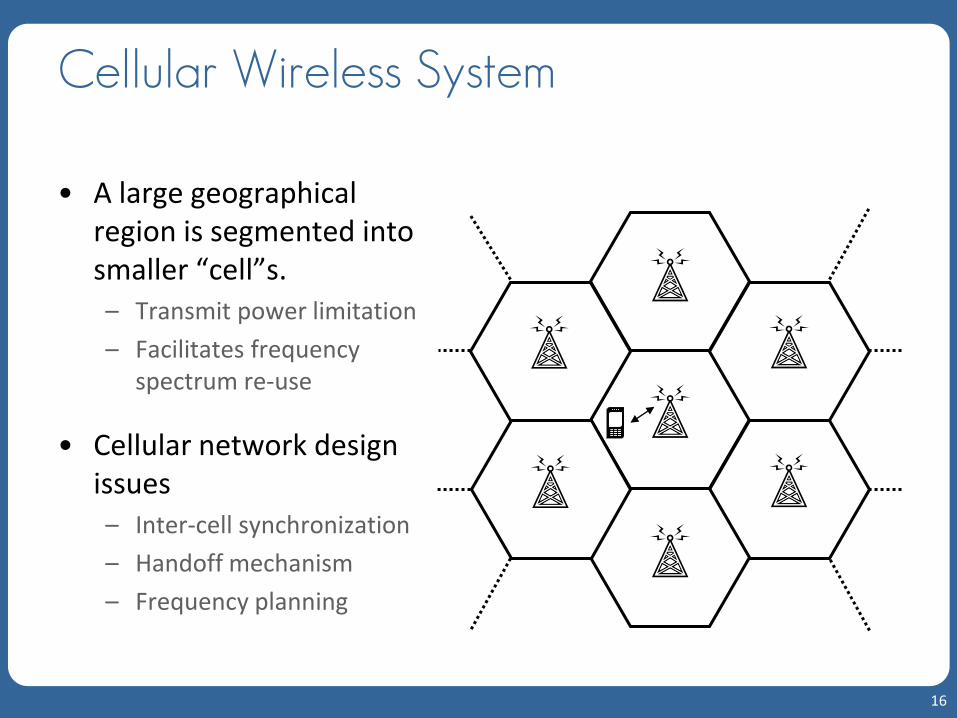
Cellular Wireless System
• A large geographical region is segmented into smaller “cell”s. – Transmit power limitation
– Facilitates frequency spectrum re-use
• Cellular network design issues – Inter-cell synchronization
– Handoff mechanism
– Frequency planning
16

Cellular Wireless System
• Frequency re-use
17
F1
F1
F1
F1
F1
F1
F1
F1
F3
F2
F7
F6
F5
F4
Frequency re-use = 1 - Higher spectral efficiency
- Higher interference for cell-edge users
Frequency re-use = 7 - Lower interference for cell-edge users
- Lower spectral efficiency
- cont.

Cellular Wireless System
• Sectorized cells
18
- cont.

Cellular Wireless System
• Frequency re-use = 3
19
- cont.

Outline
20
Wireless Background
Summary and References
Long Term Evolution (LTE)
LTE-Advanced
4G Enabling Technologies
4G Enabling Technologies
• OFDM/OFDMA
• Frequency domain equalization
• SC-FDMA
• MIMO
• Fast channel-dependent resource scheduling
21

Orthogonal Frequency Division Multiplexing
• OFDM can be viewed as a form of frequency division multiplexing (FDM). – Divides the transmission bandwidth into narrower equally spaced
tones, or subcarriers.
– Individual information symbols are conveyed over the subcarriers.
22
Ser
ial-
to-p
ara
llel
02j f te
12j f te
12 Nj f te
Input data block
Output symbol

OFDM
• Use of orthogonal subcarriers makes OFDM spectrally efficient. – Because of the orthogonality among the subcarriers, they can
overlap with each other.
23
0 1 2 3 4 5 6 7 8 9Subcarrier
- cont.

OFDM
• Since the bandwidth of each subcarrier is much smaller than the coherence bandwidth of the transmission channel, each subcarrier sees flat fading.
24
Frequency
Channel response
Subcarrier
- cont.
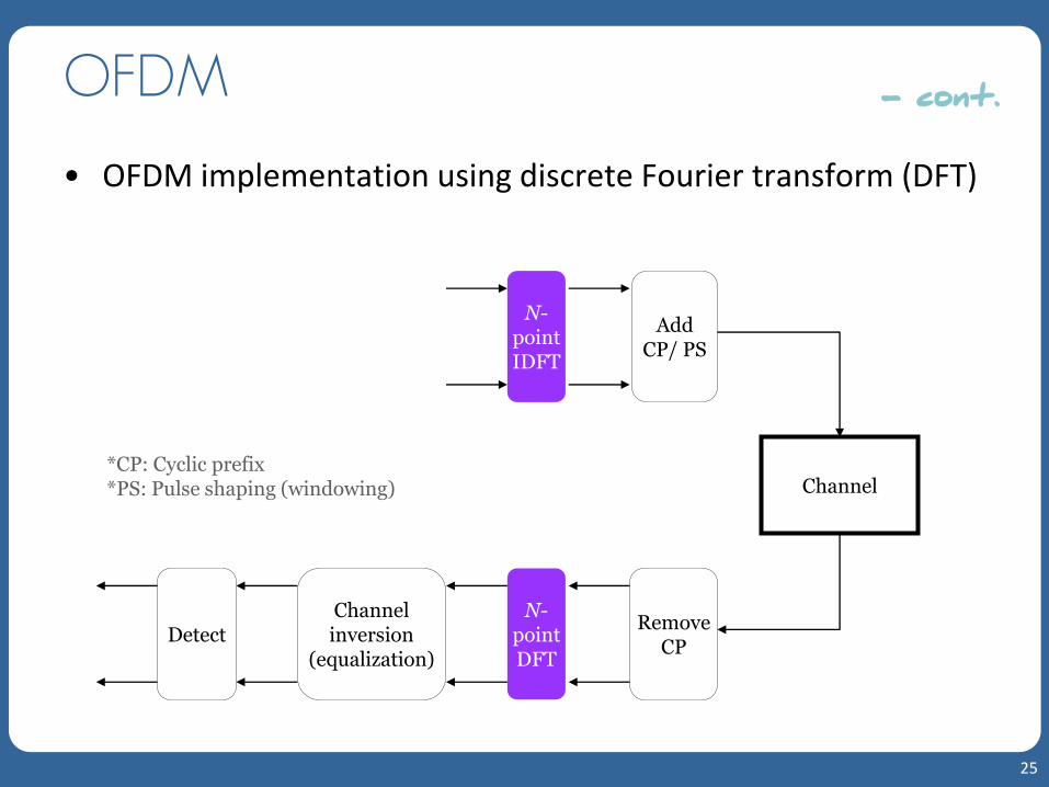
OFDM
• OFDM implementation using discrete Fourier transform (DFT)
25
Channel
Channel inversion
(equalization)
N-pointDFT
Detect Remove
CP
N-point IDFT
Add CP/ PS
*CP: Cyclic prefix *PS: Pulse shaping (windowing)
- cont.

OFDM
• Design issues of OFDM – Cyclic prefix (CP): To maintain orthogonality among subcarriers in the
presence of multi-path channel, CP longer than the channel impulse response is needed. Also CP converts linear convolution of the channel impulse response into a circular one.
– High peak-to-average power ratio (PAPR): Since the transmit signal is a composition of multiple subcarriers, high peaks occur.
– Carrier frequency offset: Frequency offset breaks the orthogonality and causes inter-carrier interference.
– Adaptive scheme or channel coding is needed to overcome the spectral null in the channel.
26
- cont.

Orthogonal Frequency Division Multiple Access
• OFDMA is a multi-user access scheme using OFDM. – Each user occupies a different set of subcarriers.
– Scheduler can exploit frequency-selectivity and multi-user diversity.
27
subcarriers
User 1
User 2
User 3

Frequency Domain Equalization
• For broadband multi-path channels, conventional time domain equalizers are impractical because of complexity. – Very long channel impulse response in the time domain.
– Prohibitively large tap size for time domain filter.
• Using discrete Fourier transform (DFT), equalization can be done in the frequency domain.
• Because the DFT size does not grow linearly with the length of the channel response, the complexity of FDE is lower than that of the equivalent time domain equalizer for broadband channel.
28
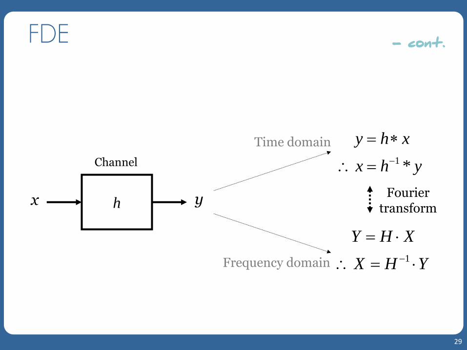
FDE
29
h x y
1 *
y h x
x h y
1
Y H X
X H Y
Time domain
Frequency domain
Fourier transform
Channel
- cont.

FDE
• In DFT, frequency domain multiplication is equivalent to time domain circular convolution.
• Cyclic prefix (CP) longer than the channel response length is needed to convert linear convolution to circular convolution.
30
CP Symbols
- cont.

FDE
• Most of the time domain equalization techniques can be implemented in the frequency domain. – MMSE equalizer, DFE, turbo equalizer, and so on.
• References – M. V. Clark, “Adaptive Frequency-Domain Equalization and
Diversity Combining for Broadband Wireless Communications,” IEEE J. Sel. Areas Commun., vol. 16, no. 8, Oct. 1998
– M. Tüchler et al., “Linear Time and Frequency Domain Turbo Equalization,” Proc. IEEE 53rd Veh. Technol. Conf. (VTC), vol. 2, May 2001
– F. Pancaldi et al., “Block Channel Equalization in the Frequency Domain,” IEEE Trans. Commun., vol. 53, no. 3, Mar. 2005
31
- cont.

Single Carrier with FDE
32
Channel N-
point IDFT
Equalization N-
pointDFT
SC/FDE
OFDM
Detect Remove
CP nxAdd CP/ PS
* CP: Cyclic Prefix, PS: Pulse Shaping
Channel Equalization N-
pointDFT
Detect Remove
CP
N-point IDFT
Add CP/ PS
nx

SC/FDE
• SC/FDE delivers performance similar to OFDM with essentially the same overall complexity, even for long channel delay.
• SC/FDE has advantage over OFDM in terms of: – Low PAPR.
– Robustness to spectral null.
– Less sensitivity to carrier frequency offset.
• Disadvantage to OFDM is that channel-adaptive subcarrier bit and power loading is not possible.
33
- cont.

SC/FDE
• References – H. Sari et al., “Transmission Techniques for Digital Terrestrial TV
Broadcasting,” IEEE Commun. Mag., vol. 33, no. 2, Feb. 1995, pp. 100-109.
– D. Falconer et al., “Frequency Domain Equalization for Single-Carrier Broadband Wireless Systems,” IEEE Commun. Mag., vol. 40, no. 4, Apr. 2002, pp. 58-66.
• Single carrier FDMA (SC-FDMA) is an extension of SC/FDE to accommodate multiple-user access.
34
- cont.

Single Carrier FDMA
• SC-FDMA is a new multiple access technique. – Utilizes single carrier modulation, DFT-spread orthogonal frequency
multiplexing, and frequency domain equalization.
• It has similar structure and performance to OFDMA.
• SC-FDMA is currently adopted as the uplink multiple access scheme in 3GPP LTE.
35
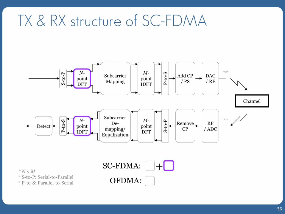
TX & RX structure of SC-FDMA
36
Subcarrier Mapping
Channel
N-point IDFT
Subcarrier De-
mapping/ Equalization
M-point DFT
Detect Remove
CP
N-point DFT
M-point IDFT
Add CP / PS
DAC / RF
RF / ADC
SC-FDMA:
OFDMA:
+ * N < M * S-to-P: Serial-to-Parallel * P-to-S: Parallel-to-Serial
P-t
o-S
S-t
o-P
S-t
o-P
P-t
o-S

Why “Single Carrier” “FDMA”?
37
Subcarrier Mapping
N-point DFT
M-point IDFT
Add CP / PS
DAC / RF
Time domain
Frequency domain
Time domain
“FDMA”
“Single Carrier”
P-t
o-S
: Sequential transmission of the symbols over a single frequency carrier.
: User multiplexing in the frequency domain.

Subcarrier Mapping
• Data block size (N) = 4, Number of users (Q) = 3, Number of subcarriers (M) = 12.
38
subcarriers
Terminal 1
Terminal 2
Terminal 3
subcarriers
Distributed Mode Localized Mode
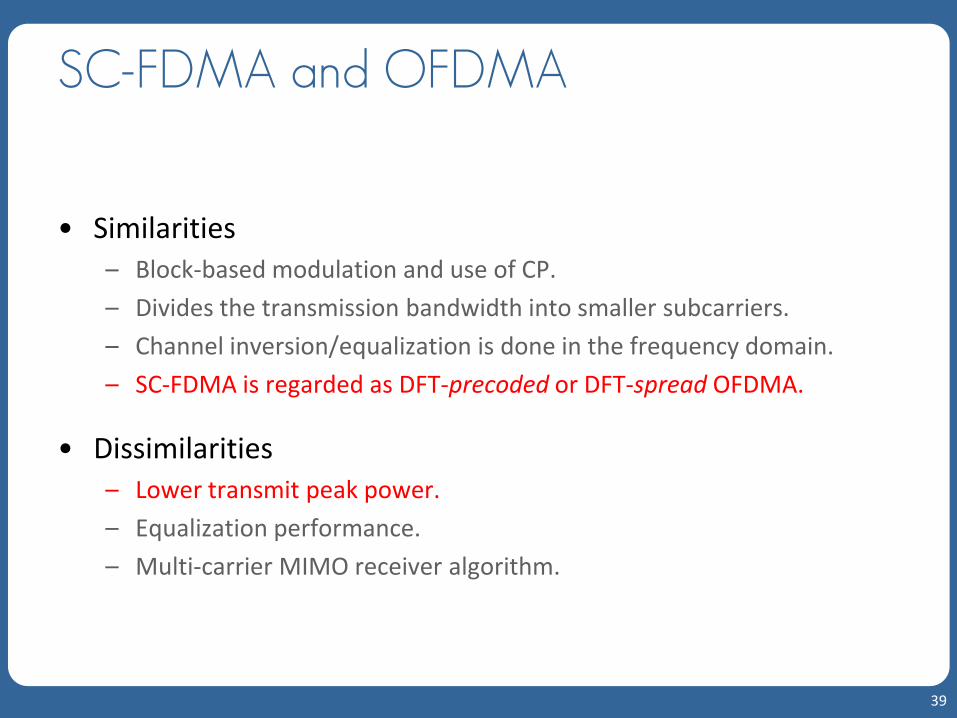
SC-FDMA and OFDMA
• Similarities – Block-based modulation and use of CP.
– Divides the transmission bandwidth into smaller subcarriers.
– Channel inversion/equalization is done in the frequency domain.
– SC-FDMA is regarded as DFT-precoded or DFT-spread OFDMA.
• Dissimilarities – Lower transmit peak power.
– Equalization performance.
– Multi-carrier MIMO receiver algorithm.
39

SC-FDMA and DS-CDMA
• In terms of bandwidth expansion, SC-FDMA is very similar to DS-CDMA system using orthogonal spreading codes. – Both spread narrowband data into broader band.
– Time symbols are compressed into “chips” after modulation.
– Spreading gain (processing gain) is achieved.
40

SC-FDMA: Comparison
41
SC-FDMA
OFDMA DS-CDMA
/FDE * DFT-based FDE
* Block-based processing & CP
* SC transmission: Low PAPR
* Time-compressed “chip” symbols
* Time-domain detection
* Subcarrier mapping: Frequency-selective scheduling

MIMO
• Multiple input multiple output (MIMO) technique improves communication link quality and capacity by using multiple transmit and receive antennas.
• Two types of gain; spatial diversity gain and spatial multiplexing gain.
42
Transmitter Receiver
MIMO channel

MIMO
• Spatial diversity – Improves link quality (SNR) by combining multiple independently
faded signal replicas.
– With Nt Tx and Nr Rx antennas, NtNr diversity gain is achievable.
– Smart antenna, Alamouti transmit diversity, and space-time coding.
• Spatial multiplexing – Increases data throughput by sending multiple streams of data
through parallel spatial channels.
– With Nt Tx and Nr Rx antennas, min(Nt,Nr) multiplexing gain is achievable.
– BLAST (Bell Labs Space-Time Architecture) and unitary precoding.
43
- cont.

Basic Idea of Spatial Diversity
• Coherent combining of multiple copies
44
1x
1y
2y
rNy
1h
* Narrowband channel
2h
rNh
Coherent combining 1x

Basic Idea of Spatial Multiplexing
• Parallel decomposition of a MIMO channel
45
1x
2x
tNx
1y
2y
rNy
11h
21h
1rNh
r tN Nh
* Narrowband channel

Basic Idea of Spatial Multiplexing
46
11 11 1 1
1
t
r r r t t r
N
N N N N N N
h hy x n
y h h x n
y H x n
H H
H H H H
I
H H H
x ny
H UDV y UDV x n
U y U U DV x U n
U y D
y x
U
D
V n
n
x
Diagonal matrix
Singular value decomposition (SVD)
- cont.

Basic Idea of Spatial Multiplexing
47
1x
2x
tNx
1y
2y
rNy
11h
21h
1rNh
r tN Nh
1x
2x
tNx
1y
2y
rNy
11d
21d
t tN Nd
* Nt < Nr
- cont.

Multicarrier MIMO Spatial Multiplexing
• Frequency domain for kth subcarrier
48
11, 1 ,1, 1, 1,
, 1, , , ,
t
r r r t t r
k kkk
k N kk k k
N k N k N N k N k N k
Y NXH
k k k k
H
k k k
H
k k k
H
k
k k k k
k k
H HY X N
Y H H X N
Y H X N
Y U Y
X V X
N U
Y D X N
N

Unitary Precoding
49
Unitary Precoding
MIMO Channel Hk
Receiver
kXkX
k kH X
kN
kY
kZ
kV
k k kX V X
H
k k k k k
k k k
U D V V X
U D X
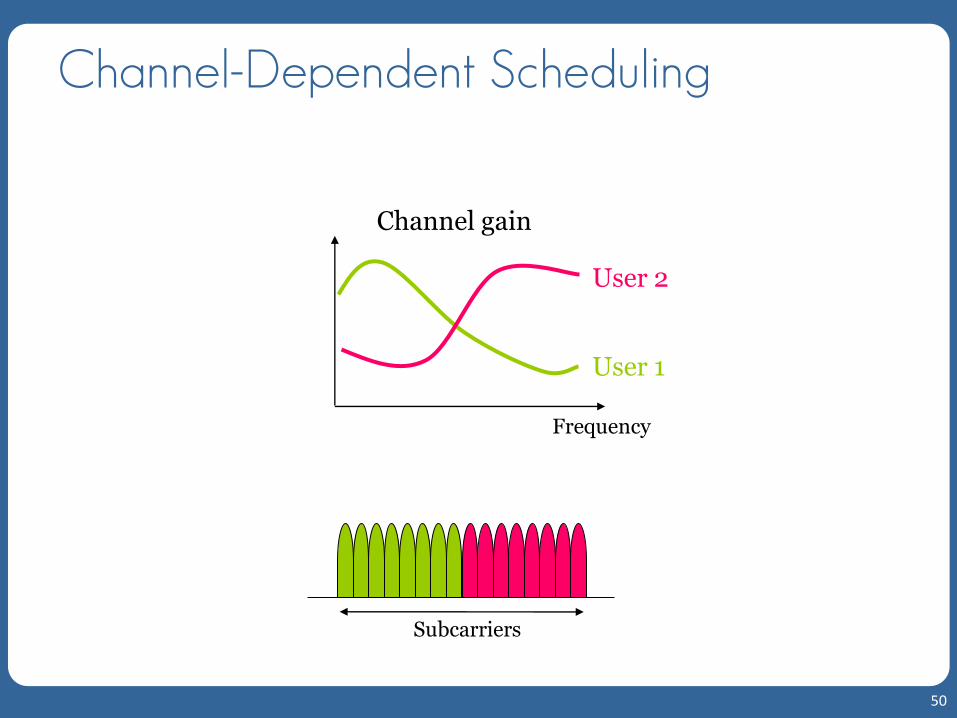
Channel-Dependent Scheduling
50
Subcarriers
Frequency
User 1
User 2
Channel gain

Channel-Dependent Scheduling
• Assign subcarriers to a user in good channel condition.
• Two subcarrier mapping schemes have advantages over each other. – Distributed: Frequency diversity.
– Localized: Frequency selective gain with CDS.
• CDS is a scheme to find an optimal set of subcarriers that are allocated to each user that maximizes some utility based on each user’s channel response.
51
- cont.

Channel-Dependent Scheduling
52
0 50 100 150 200 2500
0.5
1
1.5
2
2.5
3
Subcarriers
|Channel gain
| 2
256 total subcarriers, 16 chunks, 16 subcarriers per chunk
User 1
User 2
Chunk allocated to user 1
Chunk allocated to user 2
- cont.

Outline
53
Wireless Background
Summary and References
Long Term Evolution (LTE)
LTE-Advanced
4G Enabling Technologies

LTE: Long Term Evolution
• Standardized by 3GPP (3rd Generation Partnership Project).
• 3GPP is a partnership of 6 regional standards organizations. – ARIB (Japan)
– ATIS (USA)
– CCSA (China)
– ETSI (Europe)
– TTA (South Korea)
– TTC (Japan)
54

3GPP Evolution
• Release 99 (2000): UMTS/WCDMA
• Rel-5 (2002): HSDPA
• Rel-6 (2005): HSUPA
• Rel-7 (2007) and beyond: HSPA+
• Long Term Evolution (LTE) – 3GPP work on the Evolution started in November 2004.
– Standardized in the form of Rel-8 (Dec. 2008).
• LTE-Advanced (LTE-A) – More bandwidth (up to 100 MHz) and backward compatible with LTE.
– Standardized in the form of Rel-10 (Mar. 2011).
– Meets IMT-Advanced requirements: Real ‘4G’.
55

LTE Standardization Status
56
Rel. 8
LTE
Source: 3GPP
2009 2010 2011 2012 2008 2013
Release 10
LTE-A
Release 9
Enhancements to LTE
Release 11
LTE-A

Commercialization Status
• 31 commercially launched LTE networks (GSA, Aug. 31, 2011) – TeliaSonera: World’s first commercial LTE network launched in Dec.
2009 in Stockholm and Oslo.
– 36.1Mbps avg DL, 23ms avg latency in real world measurement (Epitiro )
– Verizon Wireless: US commercial LTE network launched in Dec. 2010 in 38 cities and 60 airports.
– 500,000 subscribers at the end of Q1, 2011
– Sold 1.2 million LTE devices during Q2, 2011
– NTT DOCOMO: Launched in Dec. 24, 2010 in the Tokyo, Nagoya, & Osaka areas.
57

Requirements of LTE
• Peak data rate – 100 Mbps DL/ 50 Mbps UL within 20 MHz bandwidth.
• Up to 200 active users in a cell (5 MHz)
• Less than 5 ms user-plane latency
• Mobility – Optimized for 0 ~ 15 km/h. – 15 ~ 120 km/h supported with high performance. – Supported up to 350 km/h or even up to 500 km/h.
• Enhanced multimedia broadcast multicast service (E-MBMS)
• Spectrum flexibility: 1.25 ~ 20 MHz
• Enhanced support for end-to-end QoS
58

Key Features of LTE (R8)
• Spectrum flexibility: 1.25 ~ 20 MHz (100 MHz for LTE-A)
• Multicarrier-based radio air interface – OFDM/OFDMA and SC-FDMA
• Support for both FDD and TDD spectrums
• Active interference avoidance and coordination
• Peak data rate (theoretical max., TR 25.912) – Downlink (DL): 326.4 Mbps (20 MHz, 4x4 MIMO, 64-QAM)
– Uplink (UL): 86.4 Mbps (20 MHz, no MIMO, 64-QAM)
59

LTE Device Category
60
Category 1 2 3 4 5
Peak rate (Mbps)
DL 10 50 100 150 300
UL 5 25 50 50 75
Source: 3GPP
RF bandwidth 20 MHz
Modulation
DL QPSK, 16-QAM, 64-QAM
UL QPSK, 16-QAM QPSK, 16-QAM, 64-
QAM
2 Rx diversity Assumed in performance requirements.
2x2 MIMO (DL) X O
4x4 MIMO (DL) X O

LTE Standard Specifications
• Freely downloadable from http://www.3gpp.org/ftp/Specs/html-info/36-series.htm
61
Specification index Description of contents
TS 36.1xx Equipment requirements: Terminals, base stations, and repeaters.
TS 36.2xx Physical layer.
TS 36.3xx Layers 2 and 3: Medium access control, radio link control, and radio resource control.
TS 36.4xx Infrastructure communications (UTRAN = UTRA Network) including base stations and mobile management entities.
TS 36.5xx Conformance testing.

Protocol Architecture
62
PHY: Physical layer
MAC: Medium Access Control
RLC: Radio Link Control
Logical channels
Transport channels
Co
ntr
ol
/ m
ea
su
re
me
nts
Layer 3
Layer 2
Layer 1
RRC: Radio Resource Control
Physical channels
Transceiver

LTE Network Architecture
• E-UTRAN (Evolved Universal Terrestrial Radio Access Network)
63
NB: NodeB (base station) RNC: Radio Network Controller SGSN: Serving GPRS Support Node GGSN: Gateway GPRS Support Node
RNC RNC
SGSN
GGSN
NB NB NB NB
UMTS 3G: UTRAN
* 3GPP TS 36.300
eNB
MME S-GW/P-GW
MME S-GW/P-GW
S1
X2
E-UTRAN
EPC (Evolved Packet Core)
eNB eNB
eNB
eNB: E-UTRAN NodeB MME: Mobility Management Entity S-GW: Serving Gateway P-GW: PDN (Packet Data Network) Gateway
* 3GPP TS 36.300

LTE Network Architecture
• eNB – All radio interface-related
functions
• MME – Manages mobility, UE
identity, and security parameters.
• S-GW – Node that terminates the
interface towards E-UTRAN.
• P-GW – Node that terminates the
interface towards PDN.
64
* 3GPP TS 36.300
eNB
MME S-GW/P-GW
MME S-GW/P-GW
S1
X2
E-UTRAN
EPC (Evolved Packet Core)
eNB eNB
eNB
eNB: E-UTRAN NodeB MME: Mobility Management Entity S-GW: Serving Gateway P-GW: PDN (Packet Data Network) Gateway
* 3GPP TS 36.300
- cont.

LTE Network Architecture
65
* Non-roaming architecture * 3GPP TS 23.401
SGi
S12
S3
S1-MME
PCRF
S7
S6a
HSS
Operator's IP Services (e.g. IMS, PSS etc.)
Rx+
S10
UE
SGSN
"LTE-Uu"
E-UTRAN
MME
S11
S5 Serving Gateway
PDN Gateway
S1-U
S4
UTRAN
GERAN
- cont.

LTE Network Architecture
66
* 3GPP TS 36.300
internet
eNB
RB Control
Connection Mobility Cont.
eNB Measurement
Configuration & Provision
Dynamic Resource
Allocation (Scheduler)
PDCP
PHY
MME
S-GW
S1
MAC
Inter Cell RRM
Radio Admission Control
RLC
E-UTRAN EPC
RRC
Mobility
Anchoring
EPS Bearer Control
Idle State Mobility
Handling
NAS Security
P-GW
UE IP address
allocation
Packet Filtering
RRM: Radio Resource Management RB: Radio Bearer RRC: Radio Resource Control PDCP: Packet Data Convergence Protocol NAS: Non-Access Stratum EPS: Evolved Packet System
- cont.

LTE Network Architecture
67
User-Plane Protocol Stack
Control-Plane Protocol Stack
* 3GPP TS 36.300
eNB
PHY
UE
PHY
MAC
RLC
MAC
PDCPPDCP
RLC
eNB
PHY
UE
PHY
MAC
RLC
MAC
MME
RLC
NAS NAS
RRC RRC
PDCP PDCP
- cont.

Frame Structure
• Two radio frame structures defined. – Frame structure type 1 (FS1): FDD.
– Frame structure type 2 (FS2): TDD.
• A radio frame has duration of 10 ms.
• A resource block (RB) spans 12 subcarriers over a slot duration of 0.5 ms. One subcarrier has bandwidth of 15 kHz, thus 180 kHz per RB.
68

Frame Structure Type 1
• FDD frame structure
69
One subframe = TTI (Transmission Time Interval)
#0 #1 #2 #3 #18 #19
One slot = 0.5 ms
One radio frame = 10 ms

Frame Structure Type 2
• TDD frame structure
70
Subframe #0 Subframe #2 Subframe #3 Subframe #4 Subframe #5 Subframe #7 Subframe #8 Subframe #9
DwPTS GP UpPTS DwPTS GP UpPTS
One subframe = 1 ms
One half-frame = 5 ms
One radio frame = 10 ms
One slot = 0.5 ms

Resource Grid
71
Slot #0 #19
One radio frame
Su
bca
rrie
r (f
req
uen
cy)
OFDM/SC-FDMA symbol (time)
RB
RB scN N
12
RB
scN
symbN
Resource block
Resource element
RB
symb scN N resource elements

Length of CP
72
symbNConfiguration
Normal CP 7
Extended CP 6
Extended CP (Df = 7.5 kHz)† 3
Configuration CP length NCP,l [samples]
Normal CP 160 ( 5.21 s) for l = 0 144 ( 4.69 s) for l = 1, 2, …, 6
Extended CP 512 ( 16.67 s) for l = 0, 1, …, 5
Extended CP (Df = 7.5 kHz) † 1024 ( 33.33 s) for l = 0, 1, 2
† Only in downlink

LTE Bandwidth/Resource Configuration
73
Channel bandwidth [MHz]
1.4 3 5 10 15 20
Number of resource blocks (NRB)
6 15 25 50 75 100
Number of occupied subcarriers
72 180 300 600 900 1200
IDFT(Tx)/DFT(Rx) size 128 256 512 1024 1536 2048
Sample rate [MHz] 1.92 3.84 7.68 15.36 23.04 30.72
Samples per slot 960 1920 3840 7680 11520 15360
*3GPP TS 36.104

Bandwidth Configuration
74
freq
uen
cy
time
300
UL RB
RB scN N
12
RB
scN
(7.68 MHz)
512
M
(4.5 MHz) (180 kHz)
Resource block
Zeros
Zeros
1 slot
DL or UL symbol
* 5 MHz system with frame structure type 1

LTE Physical Channels
• DL – Physical Downlink Shared Channel (PDSCH)
– Physical Broadcast Channel (PBCH)
– Physical Multicast Channel (PMCH)
– Physical Control Format Indicator Channel (PCFICH)
– Physical Downlink Control Channel (PDCCH)
– Physical Hybrid ARQ Indicator Channel (PHICH)
• UL – Physical Uplink Shared Channel (PUSCH)
– Physical Uplink Control Channel (PUCCH)
– Physical Random Access Channel (PRACH)
75

LTE Transport Channels
• Physical layer transport channels offer information transfer to medium access control (MAC) and higher layers.
• DL – Broadcast Channel (BCH)
– Downlink Shared Channel (DL-SCH)
– Paging Channel (PCH)
– Multicast Channel (MCH)
• UL – Uplink Shared Channel (UL-SCH)
– Random Access Channel (RACH)
76

LTE Logical Channels
• Logical channels are offered by the MAC layer.
• Control Channels: Control-plane information – Broadcast Control Channel (BCCH)
– Paging Control Channel (PCCH)
– Common Control Channel (CCCH)
– Multicast Control Channel (MCCH)
– Dedicated Control Channel (DCCH)
• Traffic Channels: User-plane information – Dedicated Traffic Channel (DTCH)
– Multicast Traffic Channel (MTCH)
77

Channel Mappings
78
PCCH BCCH CCCH DCCH DTCH MCCH MTCH Logical channels
PMCH PDCCH PBCH PDSCH
PCH DL-SCH MCH
CCCH DCCH DTCH
PUSCH PUCCH PRACH
RACH BCH UL-SCH Transport channels
Physical channels
Downlink Uplink

LTE Layer 2
• Layer 2 has three sublayers – MAC (Medium Access Control)
– RLC (Radio Link Control)
– PDCP (Packet Data Convergence Protocol)
79
DL UL
ROHC: Robust Header Compression * 3GPP TS 36.300
Segm.
ARQ etc
Multiplexing UE1
Segm.
ARQ etc...
HARQ
Multiplexing UEn
HARQ
BCCH PCCH
Scheduling / Priority Handling
Logical Channels
Transport Channels
MAC
RLCSegm.
ARQ etc
Segm.
ARQ etc
PDCP
ROHC ROHC ROHC ROHC
Radio Bearers
Security Security Security Security
...
Multiplexing
...
HARQ
Scheduling / Priority Handling
Transport Channels
MAC
RLC
PDCP
Segm.
ARQ etc
Segm.
ARQ etc
Logical Channels
ROHC ROHC
Radio Bearers
Security Security

RRC Layer
• Terminated in eNB on the network side.
• Functions – Broadcast
– Paging
– RRC connection management
– RB (Radio Bearer) management
– Mobility functions
– UE measurement reporting and control
• RRC states – RRC_IDLE
– RRC_CONNECTED
80

Resource Scheduling of Shared Channels
• Dynamic resource scheduler resides in eNB on MAC layer.
• Radio resource assignment based on radio condition, traffic volume, and QoS requirements.
• Radio resource assignment consists of: – Physical Resource Block (PRB)
– Modulation and Coding Scheme (MCS)
81

Radio Resource Management
• Radio bearer control (RBC)
• Radio admission control (RAC)
• Connection mobility control (CMC)
• Dynamic resource allocation (DRA) or packet scheduling (PS)
• Inter-cell interference coordination (ICIC)
• Load balancing (LB)
82
Other Features
• ARQ (RLC) and H-ARQ (MAC)
• Mobility
• Rate control
• DRX (Discontinuous Reception)
• MBMS
• QoS
• Security
83

DL Overview
• DL physical channels – Physical Downlink Shared Channel (PDSCH)
– Physical Broadcast Channel (PBCH)
– Physical Multicast Channel (PMCH)
– Physical Control Format Indicator Channel (PCFICH)
– Physical Downlink Control Channel (PDCCH)
– Physical Hybrid ARQ Indicator Channel (PHICH)
• DL physical signals – Reference signal (RS)
– Synchronization signal
• Available modulation for data channel – QPSK, 16-QAM, and 64-QAM
84

DL Physical Channel Processing
85
Scrambling
Modulation mapping
Layer mapping
OFDM signal generation
Resource element mapping
MIMO-related processing
Precoding
Mapping onto one or more transmission layers
Generation of signals for each antenna port
IDFT operation

DL Reference Signal
• Three types of DL reference signals – Cell-specific reference signals
• Associated with non-MBSFN transmission
– MBSFN reference signals
• Associated with MBSFN transmission
– UE-specific reference signals
86

DL Reference Signal
• Cell-specific 2D RS sequence is generated as the symbol-by- symbol product of a 2D orthogonal sequence (OS) and a 2D pseudo-random sequence (PRS). – 3 different 2D OS and ~170 different PRS.
– Each cell (sector) ID corresponds to a unique combination of one OS and one PRS ~510 unique cell IDs.
• CDM of RS for cells (sectors) of the same eNodeB (BS) – Use complex orthogonal spreading codes.
• FDM of RS for each antenna in case of MIMO
87
- cont.

DL Reference Signal
88
*With normal CP *3GPP TS 36.211
0l
0R
0R
0R
0R
6l 0l
0R
0R
0R
0R
6l
On
e an
ten
na
po
rtT
wo
an
ten
na
po
rts
Resource element (k,l)
Not used for transmission on this antenan port
Reference symbols on this antenna port
0l
0R
0R
0R
0R
6l 0l
0R
0R
0R
0R
6l 0l
1R
1R
1R
1R
6l 0l
1R
1R
1R
1R
6l
0l
0R
0R
0R
0R
6l 0l
0R
0R
0R
0R
6l 0l
1R
1R
1R
1R
6l 0l
1R
1R
1R
1R
6l
Fo
ur
ante
nn
a p
ort
s
0l 6l 0l
2R
6l 0l 6l 0l 6l
2R
2R
2R
3R 3R
3R 3R
even-numbered slots odd-numbered slots
Antenna port 0
even-numbered slots odd-numbered slots
Antenna port 1
even-numbered slots odd-numbered slots
Antenna port 2
even-numbered slots odd-numbered slots
Antenna port 3
- cont.

DL MIMO
• Supported up to 4x4 configuration.
• Support for both spatial multiplexing (SM) and Tx diversity (TxD). – SM
• Unitary precoding based scheme with codebook based feedback from user.
• Multiple codewords (up to two).
– TxD: SFBC and CDD (Cyclic Delay Diversity).
• MU-MIMO supported.
• 3G Americas, “MIMO Transmission Schemes for LTE and HSPA Networks,” Jun. 2009, available at http://3gamericas.org
89

UL Overview
• UL physical channels – Physical Uplink Shared Channel (PUSCH)
– Physical Uplink Control Channel (PUCCH)
– Physical Random Access Channel (PRACH)
• UL physical signals – Reference signal (RS)
• Available modulation for data channel – QPSK, 16-QAM, and 64-QAM
• Single user MIMO not supported in Release 8. – But it is addressed in Release 10.
– Multi-user collaborative MIMO supported.
90

UL Resource Block
91
1 slot (0.5 ms)
Resource block (RB)
Fre
qu
ency
Time
One SC-FDMA symbol
Su
bca
rrie
r
Reference symbols (RS)
*PUSCH with normal CP

UL Physical Channel Processing
92
Scrambling
Modulation mapping
Transform precoding
SC-FDMA signal generation
Resource element mapping SC-FDMA
modulation
DFT-precoding
IDFT operation

SC-FDMA Modulation in LTE UL
93
Serial-to-
Parallel
M- IDFT
N-DFT
Zeros
0 1 1, , Nx x x
Parallel-to-
Serial
0 1 1, , Mx x x
Subcarrier Mapping
sub
carr
ier
0
M-
1 Zeros
One SC-FDMA symbol
Localized mapping with an option of adaptive scheduling or random hopping.

UL Reference Signal
• Two types of UL RS
– Demodulation (DM) RS Narrowband.
– Sounding RS: Used for UL resource scheduling Broadband.
• RS based on Zadoff-Chu CAZAC (Constant Amplitude Zero Auto-Correlation) polyphase sequence – CAZAC sequence: Constant amplitude, zero circular auto-
correlation, flat frequency response, and low circular cross- correlation between two different sequences.
94
2
2 , 0,1,2, , 1; for even2
( 1)2 , 0,1,2, , 1; for odd
2
k
r kj qk k L L
L
r k kj qk k L L
L
ea
e
* r is any integer relatively prime with L and q is any integer.
B. M. Popovic, “Generalized Chirp-like Polyphase Sequences with Optimal Correlation Properties,” IEEE Trans. Info. Theory, vol. 38, Jul. 1992, pp. 1406-1409.

UL RS Multiplexing
95
subcarriers
User 1
User 2
User 3
subcarriers
FDM Pilots CDM Pilots

UL RS Multiplexing
• DM RS: Associated with PUSCH or PUCCH – For SIMO: FDM between different users.
– For MU-MIMO: CDM between RS from each antenna
• Sounding RS: Not associated with PUSCH or PUCCH – CDM when there is only one sounding bandwidth.
– CDM/FDM when there are multiple sounding bandwidths.
96
- cont.

Radio Procedures
• Cell search
• Random access
• Power control
• Uplink synchronization and uplink timing control
• Hybrid ARQ related procedures
97

LTE Release 9
• Completed in Mar. 2010.
• Enhancements to Release 8 – Enhanced DL beamforming (dual layer)
– Vocoder rate adaptation
– Self-organizing network (SON)
– Multimedia broadcast/multicast service (MBMS)
– Circuit-switched (CS) domain services
– UE positioning
– IMS emergency
98

Outline
99
Wireless Background
Summary and References
Long Term Evolution (LTE)
LTE-Advanced
4G Enabling Technologies

4G: IMT-Advanced
100
Source: 3G Americas, “Defining 4G: Understanding the ITU Process for the Next Generation of Wireless Technology”, Aug. 2008

LTE-Advanced Requirements
• Peak data rate: – 1 Gbps DL and 500 Mbps UL
• Latency – Less than 10 ms within Connected mode
– Less than 50 ms from Idle to Connected mode
• Spectrum – Up to 100 MHz bandwidth
– Support for non-consecutive bands (spectrum aggregation)
• Peak spectrum efficiency – 30 bps/Hz DL and 15 bps/Hz UL
101

LTE-A Features
• Release 10 (Completed in Mar. 2011) – Carrier aggregation
• Spectrum bonding
– Enhanced MIMO
– Heterogeneous network (HetNet)
• Macro-cell + small-cell
– Relaying
• Release 11 (To be completed in Dec. 2012) – Coordinated multi-point (CoMP) transmission and reception
– Advanced inter-cell interference coordination (ICIC)
102

LTE-A: Carrier Aggregation
• In order to support up to 100 MHz bandwidth, two or more component carriers aggregated – Component carrier (CC): Basic frequency block which comply with R8
LTE numerology
– Each CC is limited to 20 MHz bandwidth (110 resource blocks).
– Maintains backward compatibility with R8 LTE.
• Supports both contiguous and non-contiguous spectrum.
• Also supports asymmetric bandwidth for FDD.
103
- cont.

LTE-A: Carrier Aggregation
104
- cont.
20 MHz
100 MHz
CC
60 MHz Non-contiguous
20 MHz R8 LTE
60 MHz Contiguous

LTE-A: Carrier Aggregation
• Spectrum aggregation scenarios – Intra-band adjacent
– Intra-band non-adjacent
– Inter-band
• Asymmetric bandwidth for FDD
– Number of DL CC Number of UL CC
105
- cont.

LTE-A: Carrier Aggregation
• Downlink multiple access scheme – OFDMA with CC-based structure: Re-use R8 spec for low cost & fast
development
– One transport block is mapped within one CC.
• Uplink multiple access scheme – N-times DFT-spread OFDM: Clustered DFT spreading
106
- cont.

LTE-A: Enhanced MIMO
• Downlink MIMO – Up to 8x8 (8 layer) configuration
– Additional RS: CSI-RS and UE-specific DM RS
– Support for MU-MIMO
– Enhancements to CSI feedback
• Uplink MIMO – Introduction of UL transmit diversity
– Introduction of up to 4x4 SU-MIMO
– Use of turbo serial interference canceller
107

LTE-A: Relaying
• Improves coverage and cell-edge performance.
• Relay node is wirelessly connected to RAN via a donor cell.
108
Relay node Donor cell
Backhaul link

Heterogeneous Network Support
• Heterogeneous network (HetNet): Low power nodes/cells are placed throughout a macro-cell deployment as an underlay. – Low power cell: Pico/femto-cell, relay, remote radio head (RRH), etc.
109
Pico/femto-cell
Macro-cell

HetNet Support
• Supports interference coordination for both CA-based and non-CA-based HetNets.
• Ways to coordinate interference – Time domain coordination
• Introduction of ABS (Almost Blank Subframe)
• Coordinated CSI-RS
• Backhaul coordination between macro and underlay cells
– Power control
• Release 11 will add more enhancements.
110
- cont.

LTE-A: CoMP TX & RX
• Release 11 feature
• Improves coverage, cell-edge performance, and system throughput – DL: Joint processing, coordinated scheduling/beamforming
– UL: Multi-point reception
111

Outline
112
Wireless Background
Summary and References
Long Term Evolution (LTE)
LTE-Advanced
4G Enabling Technologies

Summary
• Key technologies of 4G systems – Multicarrier-based radio air interface
• OFDM/OFDMA and SC-FDMA
– Frequency domain equalization
– IP-based flat network architecture
– Multi-input multi-output (MIMO)
– Active interference avoidance and coordination
– Fast multi-carrier frequency-selective resource scheduling
113

Summary
• Key features of LTE – OFDM/SC-FDMA air interface
– Flexible 1.25 ~ 20 MHz bandwidth (up to 100 MHz in LTE-Advanced)
– Support for both FDD and TDD
– Advanced MIMO
– Peak data rate (20MHz): DL - 326.4 Mbps (4x4 MIMO), UL - 86.4 Mbps
– Low latency
114
- cont.

References and Resources
• 4G enabling technologies
– OFDM/OFDMA
• R. van Nee and R. Prasad, OFDM for Wireless Multimedia Communications, Artech House, 2000.
– Frequency domain equalization
• D. Falconer et al., “Frequency Domain Equalization for Single-Carrier Broadband Wireless Systems,” IEEE Commun. Mag., vol. 40, no. 4, Apr. 2002, pp. 58-66.
• H. Sari et al., “Transmission Techniques for Digital Terrestrial TV Broadcasting,” IEEE Commun. Mag., vol. 33, no. 2, Feb. 1995, pp. 100-109.
– SC-FDMA
• H. G. Myung & D. Goodman, Single Carrier FDMA: A New Air Interface for Long Term Evolution, John Wiley & Sons, Nov. 2008
• H. G. Myung et al., “Single Carrier FDMA for Uplink Wireless Transmission,” IEEE Vehicular Technology Mag., vol. 1, no. 3, Sep. 2006.
115

References and Resources
– MIMO
• A. Paulraj et al., Introduction to Space-Time Wireless Communications, Cambridge University Press, May 2003.
• G. L. Stüber et al., “Broadband MIMO-OFDM Wireless Communications,” Proceedings of the IEEE, Feb. 2004, vol. 92, no. 2, pp. 271-294.
– Multicarrier scheduling
• G. Song and Y. Li, “Utility-based Resource Allocation and Scheduling in OFDM-based Wireless Broadband Networks,” IEEE Commun. Mag., vol. 43, no. 12, Dec. 2005, pp. 127-134.
116
- cont.

References and Resources
• LTE – Spec
• http://www.3gpp.org/ftp/Specs/html-info/36-series.htm
– 4G Americas
• http://4gamericas.org
– LTE books
• http://www.wiley.com/WileyCDA/Section/id-WILEY2_SEARCH_RESULT.html?query=lte
– http://www.LTEwatch.com
117
- cont.

Questions? Thank you!
IEEE GLOBECOM 2011 2011.12.09 Dr. Hyung G. Myung, Qualcomm