torsional stiffness of non-uniform and hollow rigid … journal for numerical and analytical methods...
TRANSCRIPT
INTFRNATIONAL JOURNAL FOR NUMERICAL A N D ANALYTICAL METHODS I N GEOMECHANICS. VOL 9, 525-539 (1985)
TORSIONAL STIFFNESS OF NON-UNIFORM AND HOLLOW RIGID PIERS EMBEDDED IN
ISOTROPIC ELASTIC MEDIA
R. K. N. D. R A J A P A K S E ~ AND A. P. s. SELVADURAI'
Department o/ Cioil Engineering. Carleton University. Ottawa. Ontario. Connda K I S 5B6
SUMMARY
This paper examines the torsional response of a rigid pier type foundation, with a non-uniform or hollow cross-section which is embedded in bonded contact with a layered elastic half space. The tractions which act at the axisymmetric boundary surface between the pier and the surrounding elastic medium are represented by discretized regions of uniform traction. The compatibility of deformation at the boundary is used to determine the interface stress distribution. The torque -rotation response for the rigid pier foundation is obtained for different choices of the pier geometry and shear modulus mismatch between the layer and the underlying half space.
INTRODUCTION
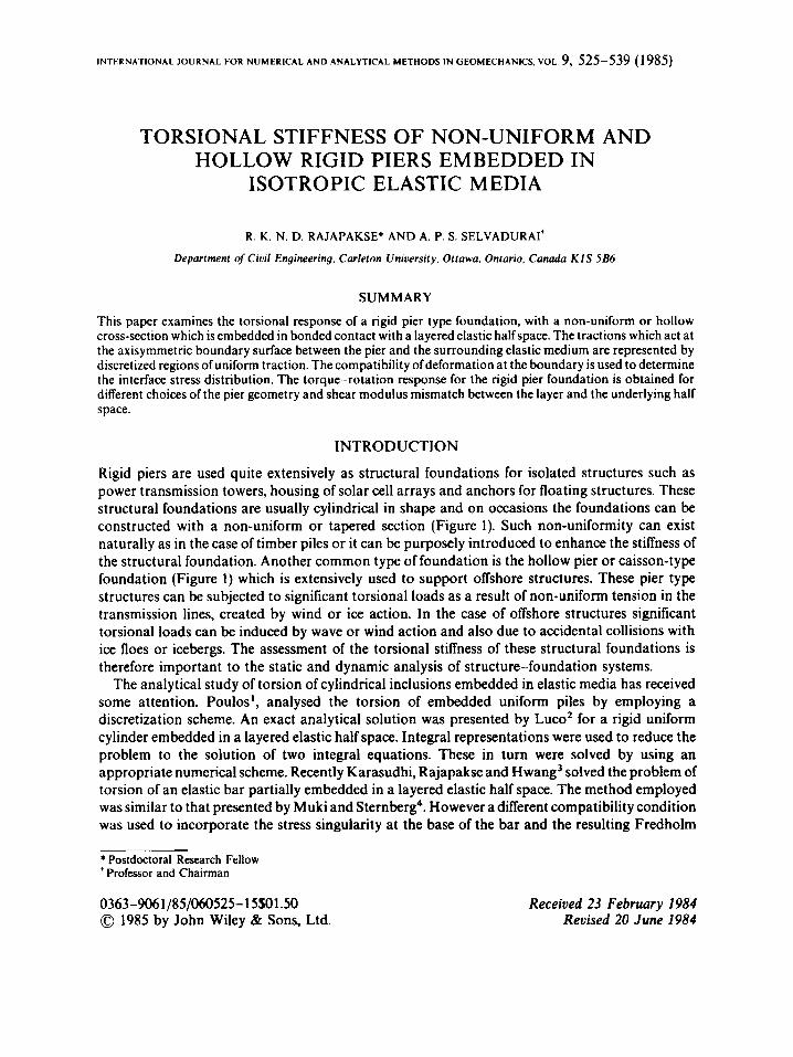
Rigid piers are used quite extensively as structural foundations for isolated structures such as power transmission towers, housing of solar cell arrays and anchors for floating structures. These structural foundations are usually cylindrical in shape and on occasions the foundations can be constructed with a non-uniform or tapered section (Figure 1). Such non-uniformity can exist naturally as in the case of timber piles or it can be purposely introduced to enhance the stiffness of the structural foundation. Another common type of foundation is the hollow pier or caisson-type foundation (Figure 1) which is extensively used to support offshore structures. These pier type structures can be subjected to significant torsional loads as a result of non-uniform tension in the transmission lines, created by wind or ice action. In the case of offshore structures significant torsional loads can be induced by wave or wind action and also due to accidental collisions with ice floes or icebergs. The assessment of the torsional stiffness of these structural foundations is therefore important to the static and dynamic analysis of structure-foundation systems.
The analytical study of torsion of cylindrical inclusions embedded in elastic media has received some attention. Poulos', analysed the torsion of embedded uniform piles by employing a discretization scheme. An exact analytical solution was presented by Luco2 for a rigid uniform cylinder embedded in a layered elastic half space. Integral representations were used to reduce the problem to the solution of two integral equations. These in turn were solved by using an appropriate numerical scheme. Recently Karasudhi, Rajapakse and Hwang3 solved the problem of torsion of an elastic bar partially embedded in a layered elastic half space. The method employed was similar to that presented by Muki and Sternberg4. However a different compatibility condition was used to incorporate the stress singularity at the base of the bar and the resulting Fredholm
* Postdoctoral Research Fellow ' Professor and Chairman
0363-9061/8S/O60525-15$Ol.~ 0 1985 by John Wiley & Sons, Ltd.
Received 23 February 1984 Revised 20 June 1984
526 R. K. N. D. RAJAPAKSE AND A. P. S. SELVADURAI
I I I
a) Uniform taper b) Step Tapering c) Hollow
Figure 1. Rigid pier foundations
integral equation was solved by employing an appropriate numerical method. In this investigation it was observed that, except for very short piers, the stress singularity at the base of the pier has a negligible effect on the computed torque-twist relationship for the embedded pier. In the above
the geometry of the bar is restricted to the simplified uniform cylindrical shape. To the authors' knowledge the problem related to the estimation of the torsional stiffness of a non- uniform rigid pier or a hollow cylindrical pier embedded in a layered half space has not been considered in the literature.
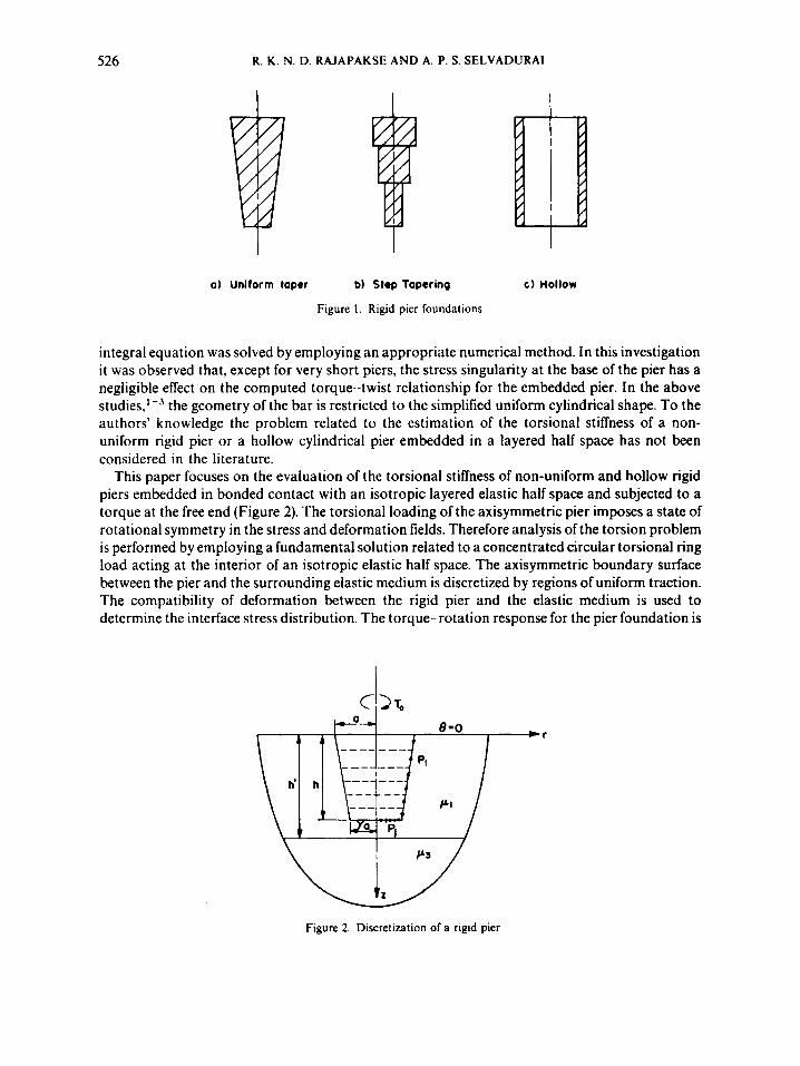
This paper focuses on the evaluation of the torsional stiffness of non-uniform and hollow rigid piers embedded in bonded contact with an isotropic layered elastic half space and subjected to a torque at the free end (Figure 2). The torsional loading of the axisymmetric pier imposes a state of rotational symmetry in the stress and deformation fields. Therefore analysis of the torsion problem is performed by employing a fundamental solution related to a concentrated circular torsional ring load acting at the interior of an isotropic elastic half space. The axisymmetric boundary surface between the pier and the surrounding elastic medium is discretized by regions of uniform traction. The compatibility of deformation between the rigid pier and the elastic medium is used to determine the interface stress distribution. The torque- rotation response for the pier foundation is
Figure 2. Discretization of a rigid pier
TORSIONAL STIFFNESS 527
obtained for different choices of the pier geometry. The numerical results are also compared with existing s o l u t i ~ n s ~ ~ ~ for uniform cylindrical piers embedded in isotropic elastic media.
FUNDAMENTAL SOLUTION
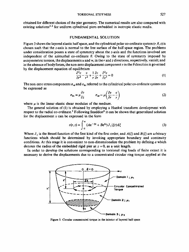
Figure 3 shows the layered elastic half space, and the cylindrical polar co-ordinate system (r.8, z) is chosen such that the z-axis is normal to the free surface of the half space region. The problems under consideration posses a state of symmetry about the z-axis and the functions involved are independent of the azimuthal co-ordinate 8. Owing to the state of symmetry imposed by axisymmetric torsion, the displacements u and w, in the r and z directions, respectively, vanish; and in the absence of body forces, the non-zero displacement component v in the 8 direction is governed by the displacement equation of equilibrium
The non-zero stress components 0,e and 0 0 , referred to the cylindrical polar co-ordinate system can be expressed as
where p is the linear elastic shear modulus of the medium. The general solution of (1) is obtained by employing a Hankel transform development with
respect to the radial co-ordinate.' Following Sneddon6 it can be shown that generalized solution for the displacement v can be expressed in the form
v(r , z ) = (Ae-<'+ Be@)J,(tr)dt 10 (3)
Where J , is the Bessel function of the first kind of the first order, and A ( t ) and B(5) are arbitrary functions which should be determined by invoking appropriate boundary and continuity conditions. At this stage it is convenient to non-dimensionalize the problem by defining a which denotes the radius of the embedded rigid pier at z = 0, as a unit length.
In order to develop the solutions corresponding to torsional ring loads of finite extent it is necessary to derive the displacements due to a concentrated circular ring torque applied at the
-a
Circular Concentrated he
t
-Domain 3 ; p3
Figure 3. Circular concentrated torque in the interior of layered half space
528 R. K. N. D. RAJAPAKSE AND A. P. S. SELVADURAI
interior of a layered half space region (see, for instance, Figure 3). By defining a fictitious plane at z = z’, we can reduce the problem to one which has three domains (see Figure 3). The superscript or subscript i ( i = 1,2,3) is used to identify the quantities associated with each domain. The displacement field in each domain has the general form given by equation (3) consisting of two functions A,(<) and Bi(() . In domain 3 however, to ensure regularity of displacements and stresses derived from equation (3) the term B 3 ( ( ) = 0 . The remaining five functions [Ai(() ( i = 1,2,3), B,(<)(i = 1,2)] are determined from the following boundary and continuity conditions
aC)(r, 0) = 0 (44 d1)(r, z’) = P ( r , z’) (4b)
ait)(r, z’) - a::+, z’) = 6(r - s)
d2)(r, h’) = d3)(r , h’)
aet)(r, h’) = aC)(r, h’)
(a) (W
The above conditions are valid for the case where z’ -= h and the corresponding expressions for the case z‘ =- h’ could be obtained in a similar fashion. The solution of the resulting system of simultaneous equations leads to the following expressions for the displacement fields in each domain. For z’ < h
For z’ 2 h
where
and
H((h’) = [(I + a) - (1 - a)e-’<*‘]/(l + a)
AXISYMMETRIC TORSION OF A RIGID PIER
We consider the problem of non-uniform rigid pier embedded in a layered elastic half space (Figure 2). It is assumed that the pier is perfectly bonded to the surrounding layered elastic half
TORSIONAL STIFFNESS 529
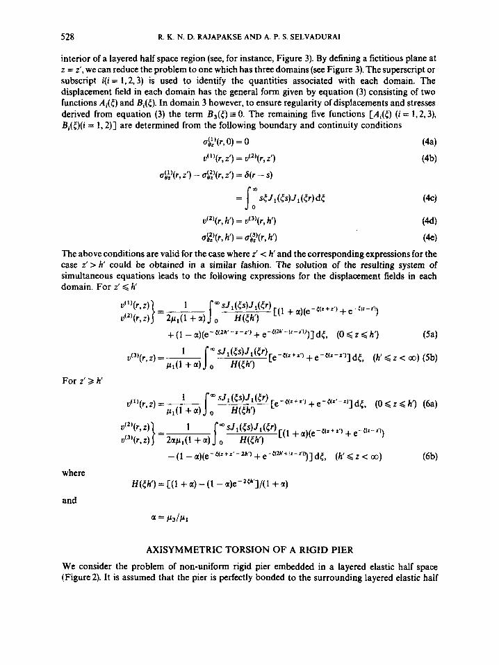
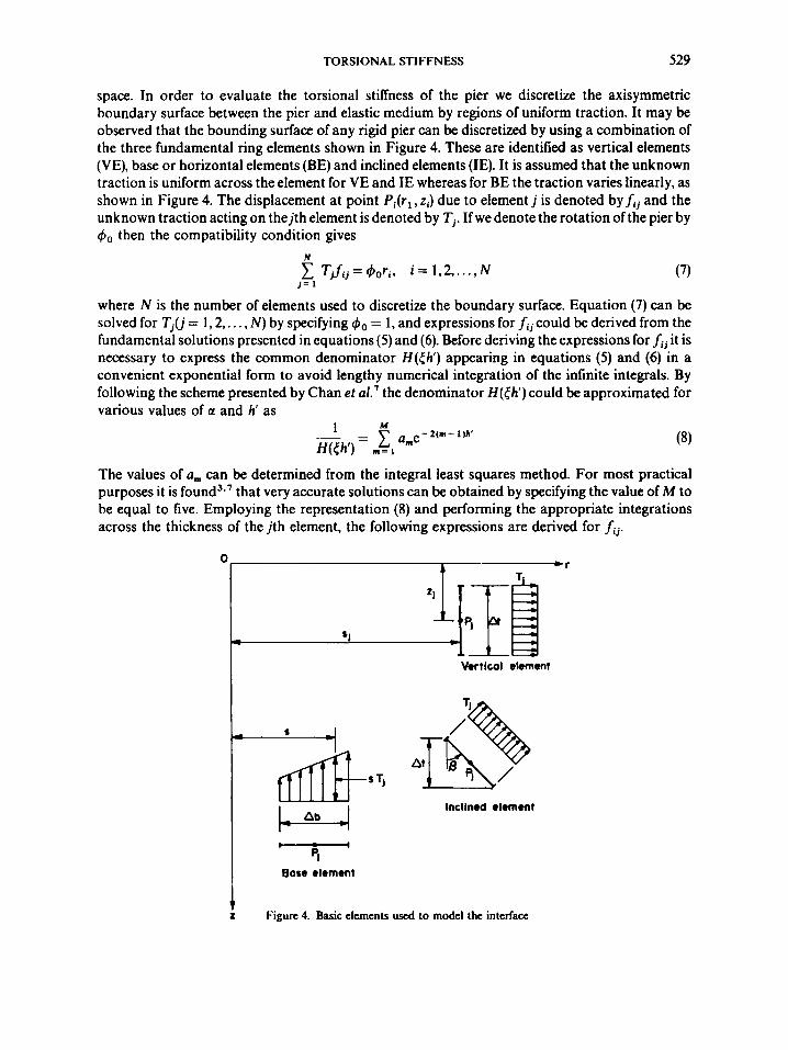
space. In order to evaluate the torsional stiffness of the pier we discretize the axisymmetric boundary surface between the pier and elastic medium by regions of uniform traction. It may be observed that the bounding surface of any rigid pier can be discretized by using a combination of the three fundamental ring elements shown in Figure 4. These are identified as vertical elements (VE), base or horizontal elements (BE) and inclined elements (IE). It is assumed that the unknown traction is uniform across the element for VE and IE whereas for BE the traction varies linearly, as shown in Figure 4. The displacement at point Pi(rl, zi) due to element j is denoted by f i j and the unknown traction acting on the jth element is denoted by Tj . If we denote the rotation of the pier by do then the compatibility condition gives
N
j = 1 Tjfij=&,ri, i = 1,2 ,..., N (7)
where N is the number of elements used to discretize the boundary surface. Equation (7) can be solved for Tj(j = 1,2,. . . , N) by specifying do = 1, and expressions for f i j could be derived from the fundamental solutions presented in equations ( 5 ) and (6). Before deriving the expressions for fij it is necessary to express the common denominator H((h‘ ) appearing in equations ( 5 ) and (6) in a convenient exponential form to avoid lengthy numerical integration of the infinite integrals. By following the scheme presented by Chan et a1.’ the denominator H((h’) could be approximated for various values of a and h’ as
The values of urn can be determined from the integral least squares method. For most practical purposes it is found3*’ that very accurate solutions can be obtained by specifying the value of M to be equal to five. Employing the representation (8) and performing the appropriate integrations across the thickness of the jth element, the following expressions are derived for f i j .
Vertical element
Inclined element - p1
Bare element
Figure 4. Basic elements used to model the interface
5 30 R. K. N. D. RAJAPAKSE A N D A. P. S. SELVADURAI
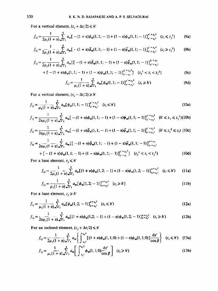
For a vertical element, (zj + At/2) < h’
For a vertical element, ( z j - At/2) 3 h‘
TORSIONAL STIFFNESS 53 1
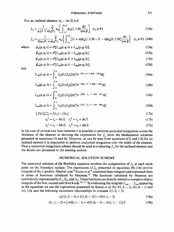
For an inclined element, ( z j - At/2) 2 h'
zj' = Z, - At/2; = zj + At12 (17b) s j l = s j - Ab/2; S; = sj + AbJ2 (174
In the case of vertical and base elements it is possible to perform analytical integration across the thickness of the element in deriving the expressions for fi, from the fundamental solutions presented in equations (5) and (6). However, as can be seen from equations (13) and (14) for an inclined element it is impossible to perform analytical integration over the width of the element. Thus a numerical integration scheme should be used in evaluating fij for the inclined element and the details are presented in the ensuing section.
NUMERICAL SOLUTION SCHEME
The numerical solution of the flexibility equation involves the computation of Lj at each mesh point on the boundary surface. The expressions of presented in equations (9)-(14) involve integrals of the Lipschitz-Hankel type.8 Eason et aL9 examined these integrals and expressed them in terms of functions tabulated by Heuman." The functions tabulated by Heuman are symbolically represented by Fo, E,, and A,. These functions are directly related to complete elliptic integrals of the first, second and third kinds.". I In evaluating the integrals l lmr . . .,I,, appearing in the equations we use the expressions presented by Eason et al. for I( 1,l ; - I), I(1,Q - 1) and I( 1,1;0), and the following recurrence relationships to evaluate I( 1,2; - 1):
s [I ( 1,2; - 1) + I ( 1,o; - 1 ) ] = 21 ( I , 1 ; - 2) (1 8 4
I(l,l;-2)=[rI(O,l;-- l ) + s f ( l , Q - 1)-cI(1,l ;- 1)]/3 (18b)
532 R. K. N. D. RAJAPAKSE AND A. P. S. SELVADURAI
where
The numerical values of F , and E , are computed by using the series expansion presented by Abramowitz and Stegun.' I Since there are no such general expansions available for A, we need to perform numerical integrations to evaluate A@ Thus in this study A, is evaluated by using the Gauss quadrature formula with thirty two quadrature points' to ensure accurate estimation of A,. It should also be mentioned here that the Lipschitz-Hankel type integrals appearing in the integrands of equations (1 3) and (14) could be computed by using E , and F , only; this provides an economical technique for the numerical integration of the integrals. In evaluating ij given by equations ( I 3) and (14) it is sufficient to use an extended Simpson's rule' integration with ten subdivisions.
Based on the above solution scheme and the associated numerical procedures the authors have developed a computer code to evaluate the stiffness of rigid piers. The inputs to the program are the shear moduli of the elastic media, co-ordinates of node points, thickness of the top layer and the values of a, appearing in equation (8). The procedures outlined previously may convey the impression that the solution scheme involves considerable numerical effort, especially when considering the number of Lipschitz-Hankel type integrals which need to be evaluated for the computation ofJj for a given pier geometry and elastic properties of the layered media. A careful inspection ofexpressions forLj reveals the fact that the values of 4,, $,,+,and $,,,are independent of elastic moduli of the media. Thus for a given pier geometry we can compute I$,,,, $,, +,,,, $,,, and store the information in the computer memory. Subsequently we can computefij for any value of a by simple multiplication of the functions by a, according to the expression for J j presented in equations (9)-( 14). In this approach we need to compute the Lipschitz-Hankel integrals only once for a given pier geometry, and computefij corresponding to as many values of a = p,/p, as desired. This scheme would result in a considerable reduction in computer time and should be followed in similar problems involving torsional loading of a layered half space region.
DISCUSSION OF RESULTS AND CONCLUSIONS
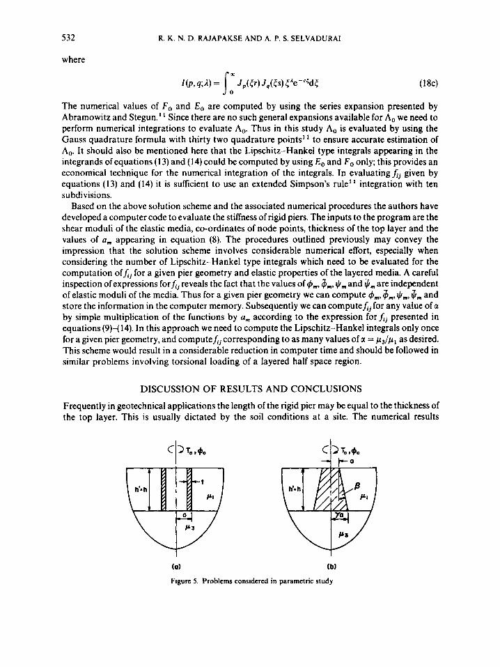
Frequently in geotechnical applications the length of the rigid pier may be equal to the thickness of the top layer. This is usually dictated by the soil conditions at a site. The numerical results
(a) ( b)
Figure 5. Problems considered in parametric study
TORSIONAL STIFFNESS
-
-
-
-
533
4.0
0.75
0.5
0.25
80
70
60
50
40
30
20
10
+Ref. 12 I il.o 0.75
0.5
0.2 5
k0
5 \ - I-
0 5 10 15 20 25 30
h /a
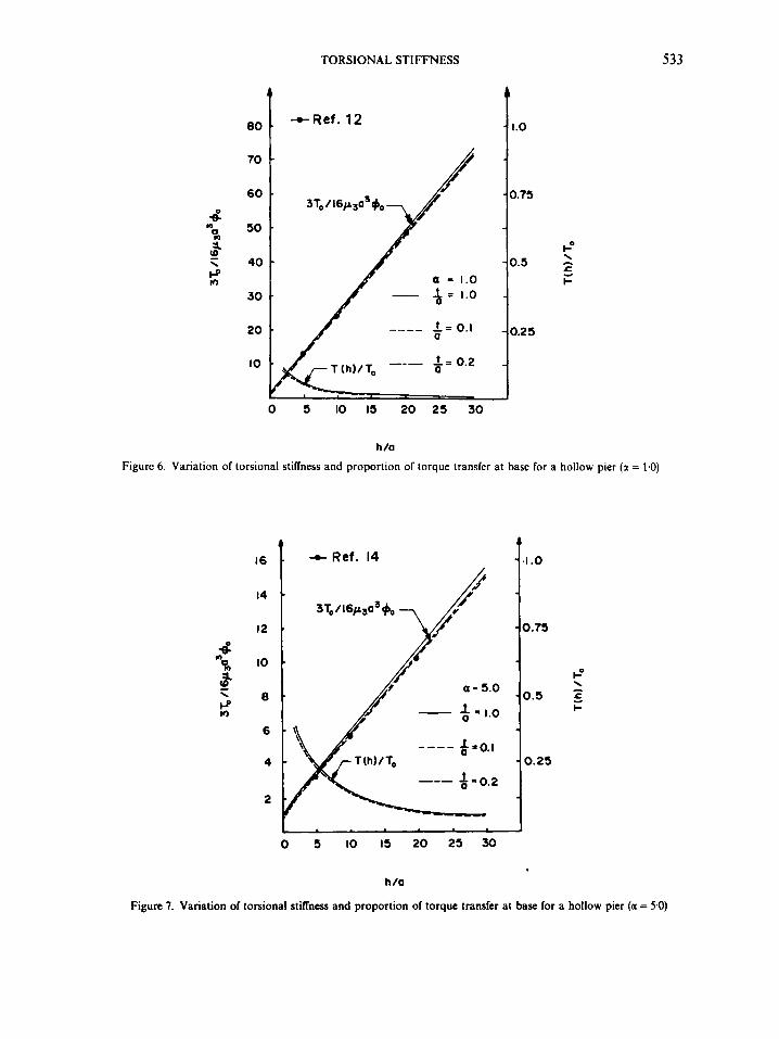
Figure 6. Variation of torsional stiffness and proportion of torque transfer at base for a hollow pier (a = 1.0)
4 "R a. !! P \
n
16
14
12
10
a
6
4
2
L + Ref. 14
t=
I J 0 5 10 15 20 25 30
h /a
Figure 7. Variation of torsional stiffness and proportion of torque transfer at base for a hollow pier (a = 5.0)
534 R. K. N. D. RAJAPAKSE AND A. P. S. SELVADURAI
8.0
6.0
4
9 n 0
!! 4.0 \
2.0
-e Ref. 12
/P p
I .o
0.75
0.5 t" f I-
0.25
0 5 10 I5 20 25 30 h /a
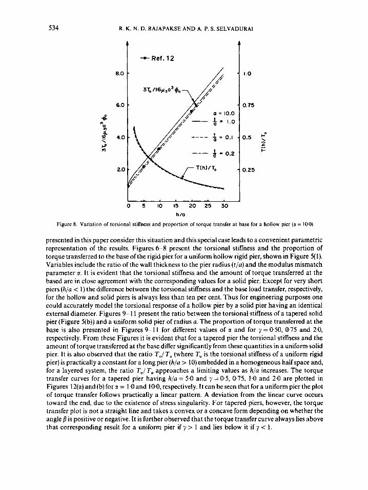
Figure 8. Variation of torsional stiffness and proportion of torque transfer at base for a hollow pier ( z = 1 0 0 )
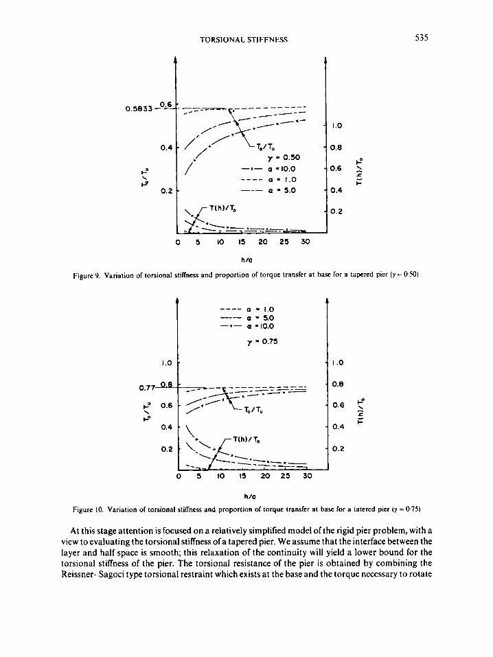
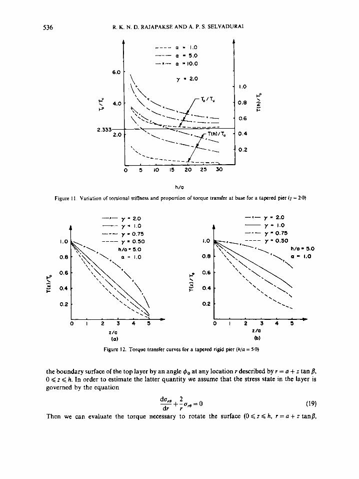
presented in this paper consider this situation and this special case leads to a convenient parametric representation of the results. Figures 6-8 present the torsional stiffness and the proportion of torque transferred to the base of the rigid pier for a uniform hollow rigid pier, shown in Figure 5( 1). Variables include the ratio of the wall thickness to the pier radius ( t /a) and the modulus mismatch parameter a. I t is evident that the torsional stiffness and the amount of torque transferred at the based are in close agreement with the corresponding values for a solid pier. Except for very short piers (h /a < 1) the difference between the torsional stiffness and the base load transfer, respectively, for the hollow and solid piers is always less than ten per cent. Thus for engineering purposes one could accurately model the torsional response of a hollow pier by a solid pier having an identical external diameter. Figures 9- 11 present the ratio between the torsional stiffness of a tapered solid pier (Figure 5(b)) and a uniform solid pier of radius a. The proportion of torque transferred at the base is also presented in Figures 9-1 1 for different values of a and for 7 = 050, 0.75 and 2.0, respectively. From these Figures it is evident that for a tapered pier the torsional stiffness and the amount of torque transferred at the base differ significantly from these quantities in a uniform solid pier. It is also observed that the ratio To/ T,, (where T,, is the torsional stiffness of a uniform rigid pier) is practically a constant for a long pier (h/a > 10) embedded in a homogeneous half space and, for a layered system, the ratio To/ T,, approaches a limiting values as h/a increases. The torque transfer curves for a tapered pier having h/a = 5.0 and y = 0.5, 075, 1.0 and 2.0 are plotted in Figures 12(a) and (b) for r = 1.0 and 100, respectively. It can be seen that for a uniform pier the plot of torque transfer follows practically a linear pattern. A deviation from the linear curve occurs toward the end, due to the existence of stress singularity. For tapered piers, however, the torque transfer plot is not a straight line and takes a convex or a concave form depending on whether the angle fl is positive or negative. It is further observed that the torque transfer curve always lies above that corresponding result for a uniform pier if y > 1 and lies below it if 7 < 1.
TORSIONAL STIFFNESS
\
I= 0.2
535
x - I- a = 1.0
a = 5.0 - 0.4
- 0 . 2
---- -
T( h 11 To
-:-.-.-.--- ---I--
1.0
h /a
Figure 9. Variation of torsional stillness and proportion of torque transfer at base for a tapered pier ( y = 050)
a = 1.0 --- a = 5.0 -*- a -10.0
----
y = 0.75
' - I .o
0 5 10 I5 20 25 30
h /o
Figure 10. Variation of torsional stillness and proportion of torque transfer at base for a tatered pier (y = 0 7 5 )
At this stage attention is focused on a relatively simplified model of the rigid pier problem, with a view to evaluating the torsional stiffness ofa tapered pier. We assume that the interface between the layer and half space is smooth; this relaxation of the continuity will yield a lower bound for the torsional stiffness of the pier. The torsional resistance of the pier is obtained by combining the Reissner- Sagoci type torsional restraint which exists at the base and the torque necessary to rotate
536 R. K. N. D. RAJAPAKSE A N D A. P. S. SELVADURAI
6.0
t' 4.0 P
2.333- 2 .o
a - 1.0 a = 5.0
-I- a = 10.0
___- ---
I .o P
0.8 - 5 \ I-
0.6
0.4
0.2
0 5 10 I5 20 25 30
h /a
Figure 11. Variation of torsional stiffness and proportion of torque transfer at base for a tapered pier ( y = 2-0)
y - 2.0 - y - 1.0
y = 0.75
-1-
4
h/a = 5.0
0.2 .
+ 0 1 2 3 4 5
I /a ( 0 )
- I - y - 2.0 y - 1.0 A - y 0.75 ---
h/a - 5.0
\ 1
\
.. \ \
\
0.2 * '. t
0 1 2 3 4 3 I /a (b)
Figure 12. Torque transfer curves for a tapered rigid pier (h/a = 5.0)
the boundary surface of the top layer by an angle &, at any location r described by r = a + z tan 8, 0 < z < h. In order to estimate the latter quantity we assume that the stress state in the layer is governed by the equation
da,e 2 +-CJ,=O dr r (19)
Then we can evaluate the torque necessary to rotate the surface (0 < z < h, r = a + z tanp,
TORSIONAL STIFFNESS 531
0 < 8 < 2n) by an angle 4o as
TI = 4np140[azh + ah2 tanp + h3 tan2fl/3]/cosp (20) The sign convention for fl is shown in Figure 5. Thus we can express the approximate torque T for a tapered bar as
T = 3
or by considering the geometry of the pier we have
when p = 0 (i.e. for a uniform bar)
which is equivalent to the approximate result given by Luco2 and Randolph.” If we examine a very long bar where (h/u) >> y 3 then
T =- r, = (7’ + + 1)/3
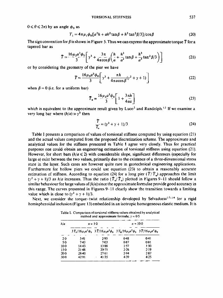
Table I presents a comparison of values of torsional stiffness computed by using equation (21) and the actual values computed from the proposed discretization scheme. The approximate and analytical values for the stiffness presented in Table I agree very closely. Thus for practical purposes one could obtain an engineering estimation of torsional stiffness using equation (2 1). However, for short bars (h/a < 2) with considerable slope, significant differences (especially for large a) exist between the two values, primarily due to the existence of a three-dimensional stress state in the layer. Such cases are however quite rare in geotechnical engineering applications. Furthermore for hollow piers we could use equation (23) to obtain a reasonably accurate estimation of stiffness. According to equation (24) for a long pier ( T / Tu) approaches the limit (yz + y + 1)/3 as h/a increases. Thus the ratio (TJ Tu) plotted in Figures 9-1 1 should follow a similar behaviour for large values of (h/a) since the approximate formulae provide good accuracy in this range. The curves presented in Figures 9-1 1 clearly show the transition towards a limiting value which is close to (y’ + y + l)/3.
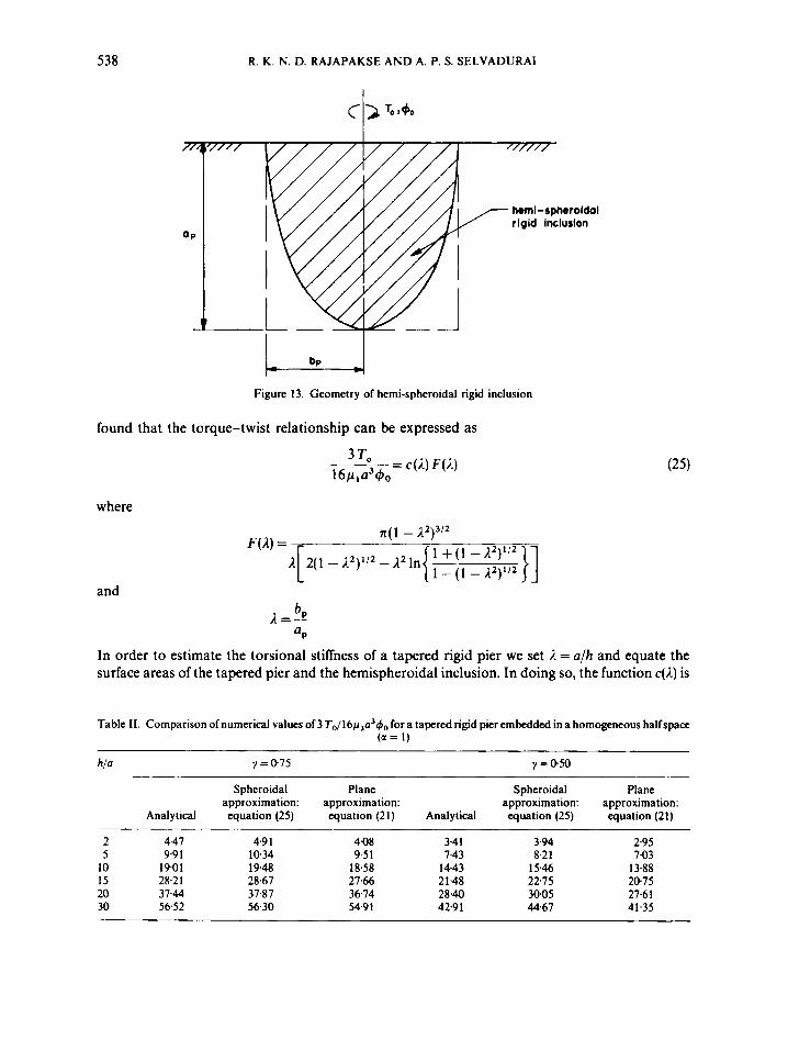
Next, we consider the torque-twist relationship developed by S e l ~ a d u r a i ’ ~ . ’ ~ for a rigid hemispheroidal inclusion (Figure 13) embedded in an isotropic homogeneous elastic medium. It is
Table 1. Comparison of torsional stifheness values obtained by analytical method and approximate formula; y = 0.5
hla a = 1.0 a = 10.0
3T0/16p,a’40 3T/16p3a’4, 3 To/16p3a340 3T/16p,034,,
2-0 3.4 1 2.95 0-48 041 5.0 7.43 7.03 087 081
10.0 14.43 13.88 1.57 1.50 15.0 21.48 20.75 2.26 2.19 200 28.40 27.6 I 2.94 2.87 30.0 42.9 1 . 41.35 4.39 4.25
538 R. K. N. D. RAJAPAKSE AND A. P. S. SELVADURAI
hwni-spheroidal
Figure 13. Geometry of hemi-spheroidal rigid inclusion
found that the torque-twist relationship can be expressed as 2 T
where
and b ;c=-r! UP
In order to estimate the torsional stiffness of a tapered rigid pier we set 2 = a/h and equate the surface areas of the tapered pier and the hemispheroidal inclusion. In doing so, the function c(1) is
Table 11. Comparison of numerical values of 3 To/16p3a’~,, fora tapered rigid pier embedded in a homogeneous halfspace (a = 1)
hia y = Q75 y = 0.50
Analytical
Spheroidal approximation: equation (25)
Plane approximation: equation (21)
2 4.47 5 9.9 1
10 19.0 1 15 28.2 1 20 37.44 30 56.52
4.9 1 4Q8 10.34 9.5 1 19.48 18.58 28.67 27.66 37.87 36.74 56.30 54.9 I
Spheroidal approximation:
Analytical equation (25)
3.4 I 3.94 7.43 8.21
14.43 1 5 4 6 21.48 22.75 28.40 30.05 42.91 44.67
Plane approximation: equation (21)
2.95 7.03
13.88 2@75 27.61 41.35
TORSIONAL STIFFNESS 539
found to be
ZysecS(1 - i2)'/* { [A( 1 - l.2)1/2 + sin- '(1 - A2)"2] c(R) =
Table I1 presents the comparison of numerical values of torsional stiffness obtained from the discretized analytical scheme, the spheroidal approximation given by equation (25) and the plane approximation given by equation (21). It is clear from the results presented in Table I1 that the approximate stiffness value computed by equation (25) provides an accurate estimation for long piers ( h / ~ >, 10). Unlike the plane approximation considered earlier the spheroidal approximation cannot be applied in cases where y > 1 or a # 1.0.
The present solution scheme does not estimate the order of stress singularity at the base of the bar; however, the numerical values of Ti confirm the existence of singular behaviour of stresses at the base. As far as global results, such as torque-twist relationships, are concerned the effects of such singularities are negligible.3 In cases where it is necessary to estimate the order of stress singularity one could apply William's method as exemplified in Reference 3 to obtain an accurate estimation of the order of singularity.
ACKNOWLEDGEMENTS
The work described in this paper was supported by a Natural Sciences and Engineering Research Council of Canada Grant No. A3866, awarded to one of the authors (APSS).
I. 2. 3.
4.
5.
6. 7.
8. 9.
10. 1 I . 12. 13.
14.
REFERENCES
H. G. Poulos, 'Torsional response of piles', J. Geotech. Eng. Dio. A S C E , 101, (GTIO), 1019-1035 (1975). J. E. Luco, 'Torsion of a rigid cylinder embedded in an elastic half space', J. Appl. Mech. ASME, 43.419-423 (1976). P. Karasudhi, R. K. N. D. Rajapakse and B. Y. Hwang, 'Torsion of a long cylindrical elastic bar partially embedded in a layered elastic half space', Int. J. Solids Struct., 20, 1-11 (1984). R. Muki and E. Sternberg. 'Elastostatic load transfer to a half space from a partially embedded axially loaded rod, Inr. J. Solids Struct., 6, 69-90 (1970). R. Muki, 'Asymmetric problems of the theory of elasticity for a semi-infinite solid and a thick plate', in I. N. Sneddon and R. Hill (eds) Progress in Solid Mechanics 1, North Holland, Amsterdam. Interscience, New York, (1960). pp. 399- 439. I. N. Sneddon, Fourier Transform, McGraw-Hill, New York, 1951. K. S. Chan, P. Karasudhi and S. L. Lee, 'Force at a point in the interior of a layered elastic half space', Int. J. Solids
G. N. Watson, A Treatise on the Theory of Bessel Functions, Cambridge University Press, 1944. G. Eason. B. Noble and 1. N. Sneddon, 'On certain integrals of Lipschitz-Hankel type involving products of Bessel functions', Phil. Trans. R. SOC. London A. 247, 529--551(1955). C. Heuman. 'Tables of complete elliptic integrals', J . Math. Phys. 20, 127-206 (1941). M. Abramowitz and I. A. Stegun, Handbook of Mathematical Functions, Dover, New York, 1972. M. F. Randolph, 'Piles subjected to torsion'. J . Geotech.. Eng. Dio. ASCE, 107, (GT8). 1095-1 11 1 (1981). A. P. S. Selvadurai, 'On the estimation of the deformability characteristics of an isotropic elastic soil medium by means of a vane test', Int. j . numer. anal. methods geomech., 3, 231-243 (1979). A. P. S. Selvadurai. 'Torsional stiffnesses of rigid piers embedded in isotropic elastic soils', in J. A. Langer, E. Mosely and C. Thompson (eds), Luterally Loaded Deep Foundations: Analysis and Performance, ASTM STP 835, pp. 49-55.
S t r ~ c t . , 10, 1179-1199(1974).