torsional behavior of reinforced concrete hollow core...
TRANSCRIPT
Journal of Engineering and Development, Vol.20, No.2,march. 2015, ISSN 1813- 7822
72
Torsional Behavior of Reinforced Concrete Hollow Core Beams
Asst. Prof Dr. Waleed Awad Waryosh* Lecturer Dr. Hadi Naser Al-Maliki* Enas Mabrok. Munaa*
M.Sc. Student *Civil Engineering Dept., College of Engineering
Al-Mustansiriya University, Baghdad, Iraq.
Abstract: The aim of this work is to study the behavior of reinforced concrete hollow
beams under torsion load. The experimental work includes investigation of eight
reinforced concrete rectangular beams of dimension (length 2000 x height 240 x
width170 mm) with the same reinforcing ratios, tested under pure torsion. Two
beam sections are provided: solid and hollow section with varied shape and
percentage (circular 18%, rectangular 18% & 27% of total cross section area of
beam). Variables considered in the test program include; effect of hollow shape &
area and concrete type (normal and high strength). Test results were discussed
based on torque - twist behavior, beam elongations, behavior and influence of
hollow core on cracking torque, ultimate torque and failure modes. Test results
indicate that the ultimate torque for hollow sections is about 89% for Circular (
hollow ratio 18%) and 83% and 60% for rectangular, of hollow ratio 18% & 27%
respectively of solid beam. The high strength concrete type in solid beam gave an
increase in the cracking and ultimate torque by about 100% and 66% respectively
and an increase in the ultimate torque was observed by about (63%, 60%, 62%)
for circular (18% ratio), rectangular (18% ratio) and rectangular (27% ratio)
respectively.
Keywords: Torsion, Reinforced Concrete, Rectangular Beams, Hollow Core.
سلوك اللي لألعتاب الخرسانية المسلحة المجوفة هادي ناصر غضبان. د.م وليد عواد وريوش . د.م.أ
إيناس مبروك موينع: طالبة الماجستير
الخالصةالبرنامج . ان الهدف من هذا البحث هو لدراسة تصرف األعتاب الخرسانية المسلحة المجوفة المقطع تحت حمل اللي
ملم 240ملم وارتفاع 2000طول ( العملي يشمل تحري وسلوك ثماني أعتاب خرسانيه مسلحه مستطيله وبأبعاد بأشكال (األعتاب كانت بمقطعين صلدة ومجوفة . فحصت تحت حمل اللي، بنفس نسبه حديد التسليح )ملم 170وعرض
شملت ). نسبه إلى مساحة المقطع العرضي للعتبة% 27و % 18و مستطيلة % 18ومساحات مختلفة الدائرية
Journal of Engineering and Development, Vol.20, No.2,march. 2015, ISSN 1813- 7822
73
اعتيادية آو عاليه ( مساحة وشكل التجويف ونوع الخرسانة : رنامج الفحص المتغيرات التي أخذت بنظر االعتبار في بااللتواء واستطالة العتبات وسلوك وتأثير اللب المجوف اعتمدت النتائج على مناقشة سلوك عزم الدوران –). المقاومة
دوران األقصى للمقاطع بينت نتائج الفحص أن عزم ال. على تشقق عزم الدوران وعزم الدوران األقصى وأنماط الفشلوبنسبه (للمقاطع ألمستطيله % 60و % 83و %) 18وبنسبه تجويف ( للمقطع الدائري% 89المجوفة كانت تقريبا
ان الخرسانة عاليه المقاومة في األعتاب الصلدة تزيد من . على التوالي من المقطع الصلد%) 27و % 18تجويف على التوالي وتزيد عزم الدوران األقصى بمقدار%) 66و % 100(عزم الدوران التشقق واألقصى بمقدار
على %) 27(والمستطيلة %) 18(المستطيلة ،%) 18(الدائرية ( للمقاطع المجوفة % ) 62و % 60و % 63( .التوالي
1. Introduction:- Structural trends today show an increase in the use of Hollow Cross Section (HCS)
members, for both building and bridge structures. This is primarily due to their advantageous
characteristics for structural as well as aesthetic aspects of design as compared to
conventional open-section members. Much advancement was made [1,2,3,4], but there are
still areas which need some improvements. Hollow cross sections are most widely known for
providing economical light weight and long span members. A longitudinal opening is used to
construct hollow core beam as cast in site, precast and pre-stressed concrete member with
continuous voids provided to reduce weight and, therefore, cost. The applications of structural
hollow sections nearly cover all fields. Sometime, hollow sections are used because of the
beauty of their shape, to express lightness or in other cases their geometrical properties
determine their use. These sections are used for the various fields such that in buildings, halls,
bridges, offshore structure and towers. In the first part of the previous century Hollow cross
sections are most widely known for providing economical solutions.
2. Objective of the Research: The proposed study is an attempt to investigate the behavior and load carrying capacity in
torsion for reinforced concrete hollow beams to show the effect of different hollow shape, hollow
area, and type of concrete that influence the torsional strength capacity and also behavior of the
beam. During the tests, the following variables will be measured for each beam:
Torque versus angle of twist values at two locations (end and quarter span).
Torque versus longitudinal elongation values at two locations of the beam
ends.
Journal of Engineering and Development, Vol.20, No.2,march. 2015, ISSN 1813- 7822
74
3. Experimental Program: The experimental program was conducted in the laboratory of the Civil Engineering Department
at College of Engineering at the University of AL-Mustansiriya. The experimental program involves
eight reinforced concrete beams under torsion load, two of these beams were solid section and six
with hollow sections. The beams were divided into two groups depending on hollow shape and
hollow area and concrete type. Each group contains one solid and three hollow sections. The cross
section of the beams (b x h), was (170 x 240 mm) and length 2000 mm as shown in Fig. (1). To avoid
failure of the specimen at cracking, minimum steel reinforcement in both longitudinal and transverse
directions was provided for torsion requirements. The total ratio of volume of stirrups and
longitudinal reinforcement to the volume of the concrete was taken as 1.96% to avoid failure of the
beams at torsion cracking load [5,6]. All beams had the same cross section & reinforcing and the
length of the hollow part was 1400 mm in the longitudinal direction of the beam. The details of the
beams are listed in Table (1, 2 and 3).
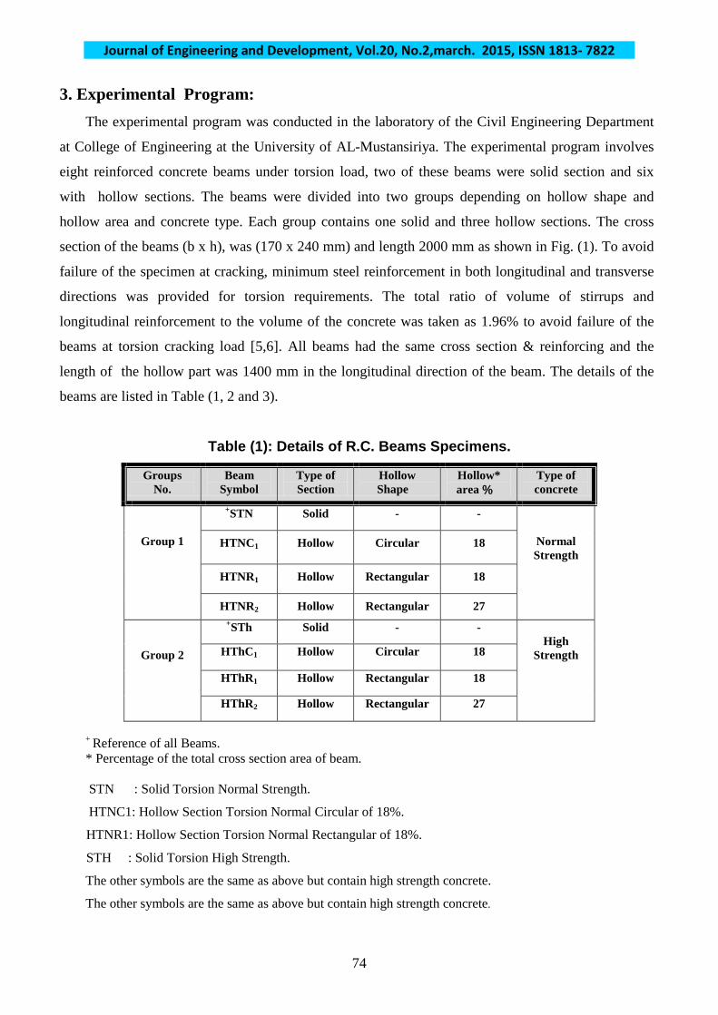
Table (1): Details of R.C. Beams Specimens.
Groups No.
Beam Symbol
Type of Section
Hollow Shape
Hollow* area %
Type of concrete
Group 1
STN+ Solid - -
Normal Strength
HTNC1 Hollow Circular 18
HTNR1 Hollow Rectangular 18
HTNR2 Hollow Rectangular 27
Group 2
STh+ Solid - - High
Strength HThC1 Hollow Circular 18
HThR1 Hollow Rectangular 18
HThR2 Hollow Rectangular 27
+ Reference of all Beams. * Percentage of the total cross section area of beam. STN : Solid Torsion Normal Strength.
HTNC1: Hollow Section Torsion Normal Circular of 18%.
HTNR1: Hollow Section Torsion Normal Rectangular of 18%.
STH : Solid Torsion High Strength.
The other symbols are the same as above but contain high strength concrete.
The other symbols are the same as above but contain high strength concrete.

Journal of Engineering and Development, Vol.20, No.2,march. 2015, ISSN 1813- 7822
75
a: Solid Beam Specimen.
b: Hollow Beam Specimens.
Fig. (1): Cross Sections Dimensions, Reinforcement Details of the Tested Specimens.
Journal of Engineering and Development, Vol.20, No.2,march. 2015, ISSN 1813- 7822
76
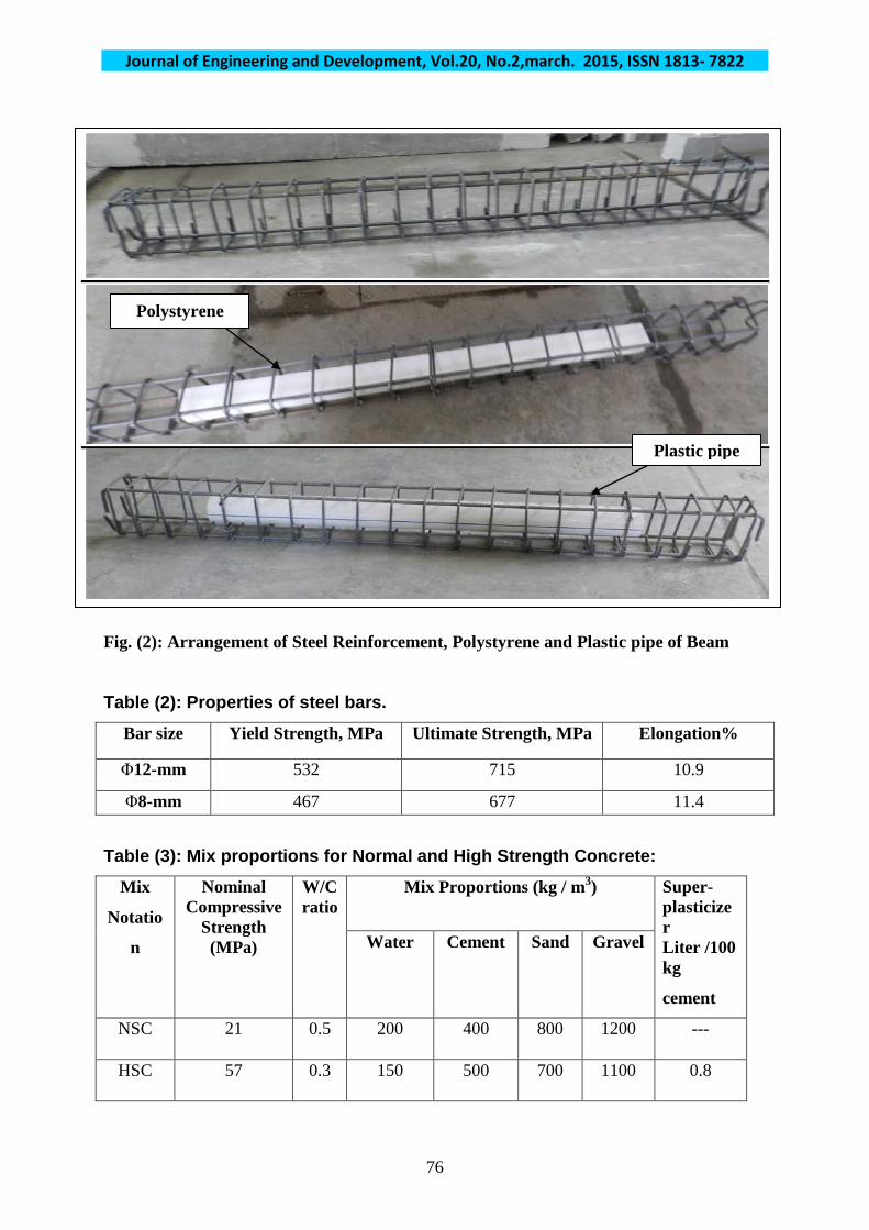
Fig. (2): Arrangement of Steel Reinforcement, Polystyrene and Plastic pipe of Beam
Table (2): Properties of steel bars.
Bar size Yield Strength, MPa Ultimate Strength, MPa Elongation%
Φ12-mm 532 715 10.9
Φ8-mm 467 677 11.4
Table (3): Mix proportions for Normal and High Strength Concrete:
Mix
Notatio
n
Nominal Compressive
Strength (MPa)
W/C ratio
Mix Proportions (kg / m3) Super- plasticizer Liter /100 kg
cement
Water Cement Sand Gravel
NSC 21 0.5 200 400 800 1200 ---
HSC 57 0.3 150 500 700 1100 0.8
Polystyrene
Plastic pipe

Journal of Engineering and Development, Vol.20, No.2,march. 2015, ISSN 1813- 7822
77
4. Test Setup:
The hydraulic universal testing machine (MFL system) was used to test the beam specimens. The
normal load can just be applied by this machine on the specimen at several points. In this research the
applied loads outside the bed of the universal machine are needed in order to get torsional movement.
The special clamping loading frame on each end of the beam was used as shown in Fig. (3). This
frame consists of two large steel clamps which work as arms for applied torque with separated faces to
connect them over the sample by large bolts; four bolts are used for each arm. This frame is made of
thick steel plate (10 mm) with two steel shafts attached by welding. The final shape is similar to a
bracket. These arms were capable of providing a maximum eccentricity of (500mm) with respect to the
longitudinal axis of the beam. In order to get pure torsion the center of support should coincide with the
center of the moment arm. Steel girder of (300 mm) depth and (3 m) length is used to transmit the loads
from the center of the universal machine to the two arms (pure torsion). This girder was clamped to the
universal machine as shown in Fig. (3)
Fig.(3) Test setup & Arrangement Specimens and Instrumentation.
Journal of Engineering and Development, Vol.20, No.2,march. 2015, ISSN 1813- 7822
78
5. Measuring Instruments
5.1 Angle of Twist Measurements A simple method was used to estimate the angle of twist by using two dial
gages having an accuracy of (0.01 mm) attached the side fiber of the end and quarter
of beam as shown in Fig. (3). 5.2 Elongation Measurements
Two dial gages having an accuracy of (0.01 mm) were fixed at the center of
the beam side ends to measure the elongation of the beam as shown in Fig. (3).
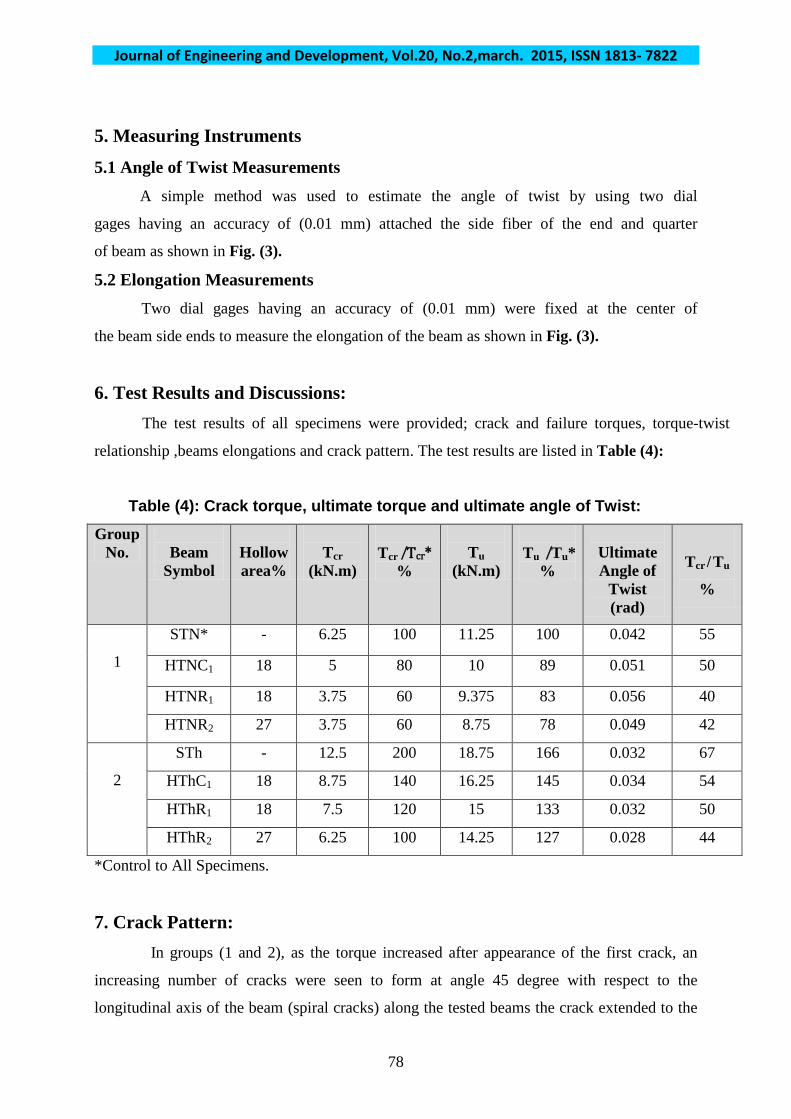
6. Test Results and Discussions: The test results of all specimens were provided; crack and failure torques, torque-twist
relationship ,beams elongations and crack pattern. The test results are listed in Table (4):
Table (4): Crack torque, ultimate torque and ultimate angle of Twist: Group
No.
Beam Symbol
Hollow area%
Tcr
(kN.m)
Tcr ̸Tcr*
%
Tu
(kN.m)
Tu ̸Tu*
%
Ultimate Angle of
Twist (rad)
Tcr ̸ Tu
%
1
STN* - 6.25 100 11.25 100 0.042 55
HTNC1 18 5 80 10 89 0.051 50
HTNR1 18 3.75 60 9.375 83 0.056 40
HTNR2 27 3.75 60 8.75 78 0.049 42
2
STh - 12.5 200 18.75 166 0.032 67
HThC1 18 8.75 140 16.25 145 0.034 54
HThR1 18 7.5 120 15 133 0.032 50
HThR2 27 6.25 100 14.25 127 0.028 44
*Control to All Specimens.
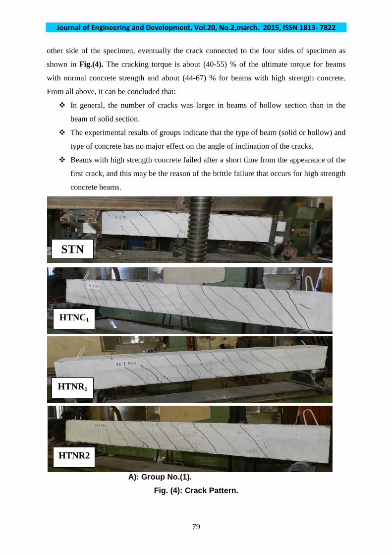
7. Crack Pattern: In groups (1 and 2), as the torque increased after appearance of the first crack, an
increasing number of cracks were seen to form at angle 45 degree with respect to the
longitudinal axis of the beam (spiral cracks) along the tested beams the crack extended to the
Journal of Engineering and Development, Vol.20, No.2,march. 2015, ISSN 1813- 7822
79
other side of the specimen, eventually the crack connected to the four sides of specimen as
shown in Fig.(4). The cracking torque is about (40-55) % of the ultimate torque for beams
with normal concrete strength and about (44-67) % for beams with high strength concrete.
From all above, it can be concluded that:
In general, the number of cracks was larger in beams of hollow section than in the
beam of solid section.
The experimental results of groups indicate that the type of beam (solid or hollow) and
type of concrete has no major effect on the angle of inclination of the cracks.
Beams with high strength concrete failed after a short time from the appearance of the
first crack, and this may be the reason of the brittle failure that occurs for high strength
concrete beams.
A): Group No.(1). Fig. (4): Crack Pattern.
STN
HTNC1
HTNR1
HTNR2

Journal of Engineering and Development, Vol.20, No.2,march. 2015, ISSN 1813- 7822
80
(B): Group No.(2). Fig. (4): Continue.
STh
STh
HThC1
HThR1
HThR2
STh
Journal of Engineering and Development, Vol.20, No.2,march. 2015, ISSN 1813- 7822
81
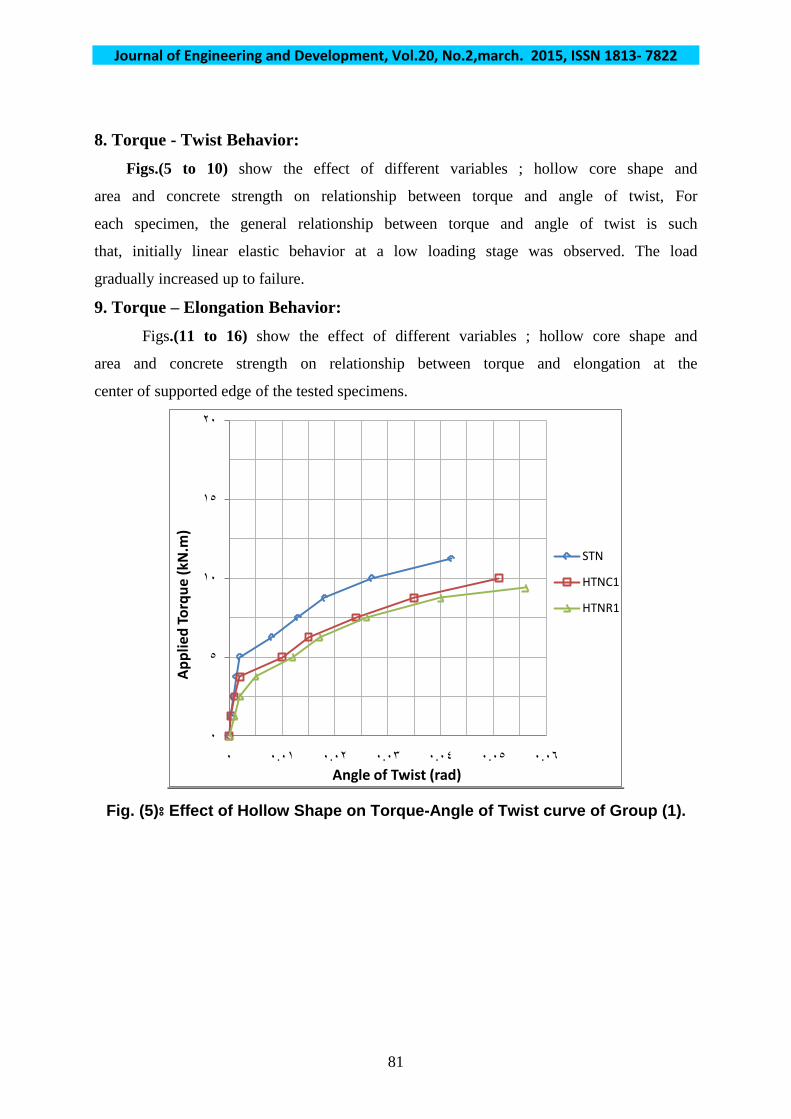
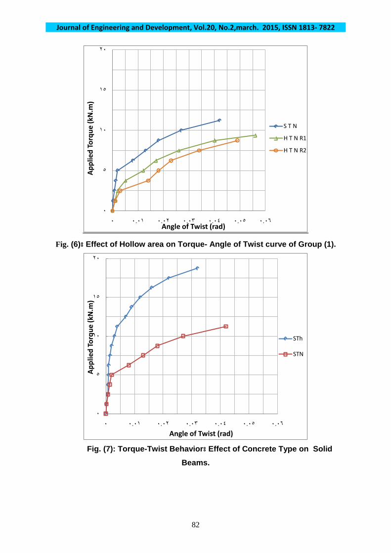
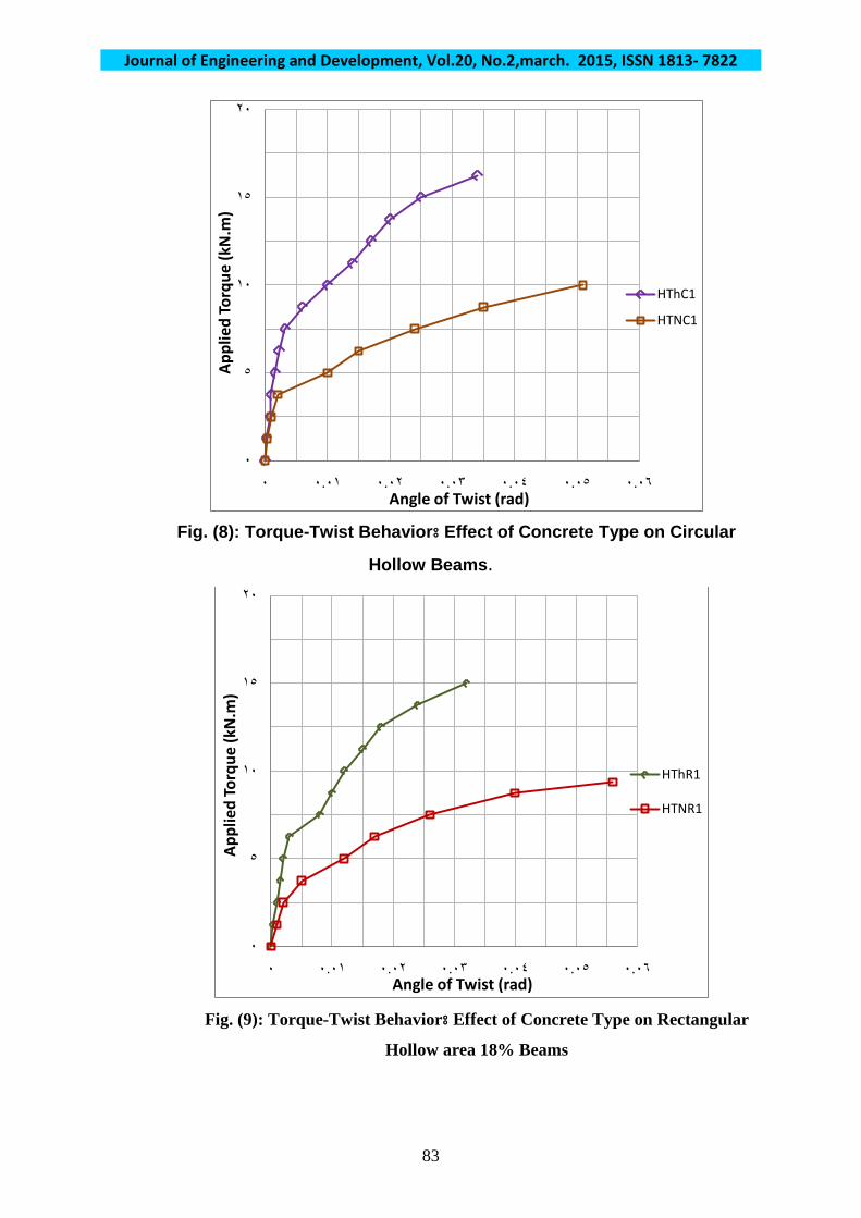
8. Torque - Twist Behavior: Figs.(5 to 10) show the effect of different variables ; hollow core shape and
area and concrete strength on relationship between torque and angle of twist, For
each specimen, the general relationship between torque and angle of twist is such
that, initially linear elastic behavior at a low loading stage was observed. The load
gradually increased up to failure.
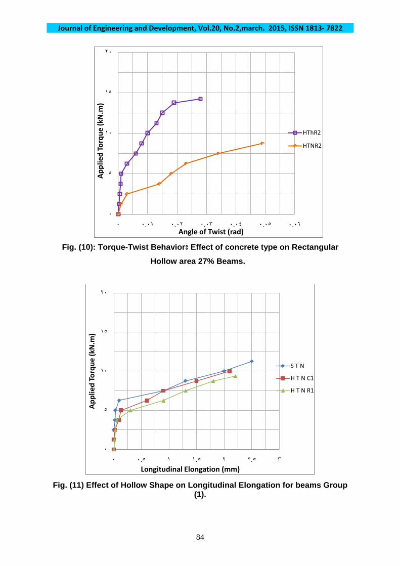
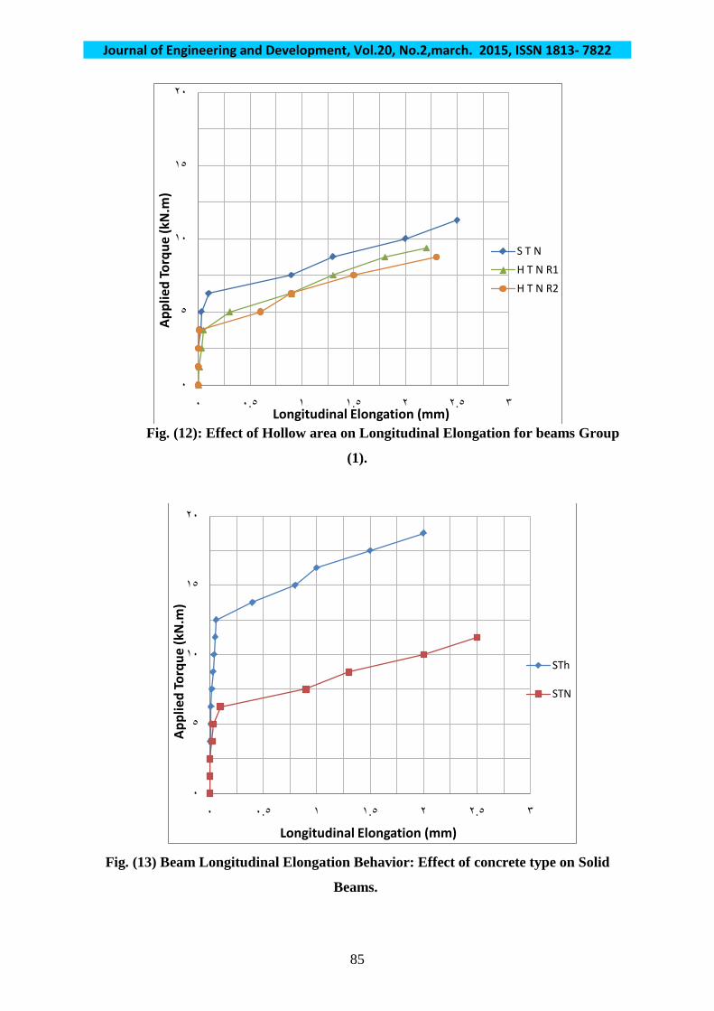
9. Torque – Elongation Behavior: Figs.(11 to 16) show the effect of different variables ; hollow core shape and
area and concrete strength on relationship between torque and elongation at the
center of supported edge of the tested specimens.
Fig. (5)⦂ Effect of Hollow Shape on Torque-Angle of Twist curve of Group (1).
۰
٥
۱۰
۱٥
۲۰
۰ ۰.۰۱ ۰.۰۲ ۰.۰۳ ۰.۰٤ ۰.۰٥ ۰.۰٦
Appl
ied
Torq
ue (k
N.m
)
Angle of Twist (rad)
STN
HTNC1
HTNR1
Journal of Engineering and Development, Vol.20, No.2,march. 2015, ISSN 1813- 7822
82
Fig. (6)⦂ Effect of Hollow area on Torque- Angle of Twist curve of Group (1).
Fig. (7): Torque-Twist Behavior⦂ Effect of Concrete Type on Solid
Beams.
۰
٥
۱۰
۱٥
۲۰
۰ ۰.۰۱ ۰.۰۲ ۰.۰۳ ۰.۰٤ ۰.۰٥ ۰.۰٦
Appl
ied
Torq
ue (k
N.m
)
Angle of Twist (rad)
S T N
H T N R1
H T N R2
۰
٥
۱۰
۱٥
۲۰
۰ ۰.۰۱ ۰.۰۲ ۰.۰۳ ۰.۰٤ ۰.۰٥ ۰.۰٦
Appl
ied
Torq
ue (k
N.m
)
Angle of Twist (rad)
STh
STN
Journal of Engineering and Development, Vol.20, No.2,march. 2015, ISSN 1813- 7822
83
Fig. (8): Torque-Twist Behavior⦂ Effect of Concrete Type on Circular
Hollow Beams.
Fig. (9): Torque-Twist Behavior⦂ Effect of Concrete Type on Rectangular
Hollow area 18% Beams
۰
٥
۱۰
۱٥
۲۰
۰ ۰.۰۱ ۰.۰۲ ۰.۰۳ ۰.۰٤ ۰.۰٥ ۰.۰٦
Appl
ied
Torq
ue (k
N.m
)
Angle of Twist (rad)
HThC1
HTNC1
۰
٥
۱۰
۱٥
۲۰
۰ ۰.۰۱ ۰.۰۲ ۰.۰۳ ۰.۰٤ ۰.۰٥ ۰.۰٦
Appl
ied
Torq
ue (k
N.m
)
Angle of Twist (rad)
HThR1
HTNR1
Journal of Engineering and Development, Vol.20, No.2,march. 2015, ISSN 1813- 7822
84
Fig. (10): Torque-Twist Behavior⦂ Effect of concrete type on Rectangular
Hollow area 27% Beams.
Fig. (11) Effect of Hollow Shape on Longitudinal Elongation for beams Group
(1).
۰
٥
۱۰
۱٥
۲۰
۰ ۰.۰۱ ۰.۰۲ ۰.۰۳ ۰.۰٤ ۰.۰٥ ۰.۰٦
Appl
ied
Torq
ue (k
N.m
)
Angle of Twist (rad)
HThR2
HTNR2
۰
٥
۱۰
۱٥
۲۰
۰ ۰.٥ ۱ ۱.٥ ۲ ۲.٥ ۳
Appl
ied
Torq
ue (k
N.m
)
Longitudinal Elongation (mm)
S T N
H T N C1
H T N R1
Journal of Engineering and Development, Vol.20, No.2,march. 2015, ISSN 1813- 7822
85
Fig. (12): Effect of Hollow area on Longitudinal Elongation for beams Group
(1).
Fig. (13) Beam Longitudinal Elongation Behavior: Effect of concrete type on Solid
Beams.
۰
٥
۱۰
۱٥
۲۰
۰ ۰.٥ ۱ ۱.٥ ۲ ۲.٥ ۳
Appl
ied
Torq
ue (k
N.m
)
Longitudinal Elongation (mm)
S T NH T N R1H T N R2
۰
٥
۱۰
۱٥
۲۰
۰ ۰.٥ ۱ ۱.٥ ۲ ۲.٥ ۳
Appl
ied
Torq
ue (k
N.m
)
Longitudinal Elongation (mm)
STh
STN

Journal of Engineering and Development, Vol.20, No.2,march. 2015, ISSN 1813- 7822
86
Fig. (14) Beam Longitudinal Elongation Behavior: Effect of concrete type on Circular
Hollow Beams.
Fig. (15): Beam Longitudinal Elongation Behavior: Effect of concrete type on
Rectangular Hollow area 18% Beams.
۰
٥
۱۰
۱٥
۲۰
۰ ۰.٥ ۱ ۱.٥ ۲ ۲.٥ ۳
Appl
ied
Torq
ue (k
N.m
)
Longitudinal Elongation (mm)
HThC1
HTNC1
۰
٥
۱۰
۱٥
۲۰
۰ ۰.٥ ۱ ۱.٥ ۲ ۲.٥ ۳
Appl
ied
Torq
ue (k
N.m
)
Longitudinal Elongation (mm)
HThR1
HTNR1
Journal of Engineering and Development, Vol.20, No.2,march. 2015, ISSN 1813- 7822
87
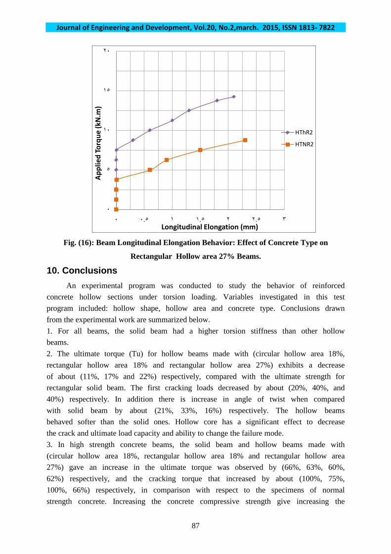
Fig. (16): Beam Longitudinal Elongation Behavior: Effect of Concrete Type on
Rectangular Hollow area 27% Beams.
10. Conclusions
An experimental program was conducted to study the behavior of reinforced concrete hollow sections under torsion loading. Variables investigated in this test program included: hollow shape, hollow area and concrete type. Conclusions drawn from the experimental work are summarized below. 1. For all beams, the solid beam had a higher torsion stiffness than other hollow beams. 2. The ultimate torque (Tu) for hollow beams made with (circular hollow area 18%, rectangular hollow area 18% and rectangular hollow area 27%) exhibits a decrease of about (11%, 17% and 22%) respectively, compared with the ultimate strength for rectangular solid beam. The first cracking loads decreased by about (20%, 40%, and 40%) respectively. In addition there is increase in angle of twist when compared with solid beam by about (21%, 33%, 16%) respectively. The hollow beams behaved softer than the solid ones. Hollow core has a significant effect to decrease the crack and ultimate load capacity and ability to change the failure mode. 3. In high strength concrete beams, the solid beam and hollow beams made with (circular hollow area 18%, rectangular hollow area 18% and rectangular hollow area 27%) gave an increase in the ultimate torque was observed by (66%, 63%, 60%, 62%) respectively, and the cracking torque that increased by about (100%, 75%, 100%, 66%) respectively, in comparison with respect to the specimens of normal strength concrete. Increasing the concrete compressive strength give increasing the
۰
٥
۱۰
۱٥
۲۰
۰ ۰.٥ ۱ ۱.٥ ۲ ۲.٥ ۳
Appl
ied
Torq
ue (k
N.m
)
Longitudinal Elongation (mm)
HThR2
HTNR2
Journal of Engineering and Development, Vol.20, No.2,march. 2015, ISSN 1813- 7822
88
stiffness of beam and decreasing the angle of twist (23%, 33%, 42%, 42%) and decrease the longitudinal elongation. 4. In general, the number of cracks was larger in the hollow sections than in the solid ones. 5. It has been observed from the tests carried out that the slope of cracks under pure torsion is about 45o. 6. For all cases, circular hollow core is better than rectangular hollow core to resist more cracking and ultimate loads. 11. References: 1- Meng, J., Werasak R. and Zhongxian L. "Torsional strengthening of
Reinforced Concrete Box Beams Using Carbon Fiber Reinforced Polymer."
Composite Structures Journal, Vol. 78, 2007, pp. 264–270.
2- Hsu, T.T.C., “Torsion of Reinforced Concrete”, Van Nostrand Reinhold
Company, New York, 1984, 494 pp.
3- ACI Committee 318M, "Building Code Requirements for Reinforced Concrete
(ACI 318-11)", American Concrete Institute, Detroit, 2011.
4- Collins, M. P. “Stress-Strain Characteristics of Reinforced Concrete in Pure
Shear,” Inelasticity and Non-Linearity in Structural Concrete, Study No. 8,
University of Waterloo Press, 1973, pp. 211-225.
5- MacGregor, J.M. and Ghoneim, M.G. “Design for Torsion.” Structural
Journal, American Concrete Institute, Vol. 92, No. 2, 1995, pp. 211-218.
6- Hsu,T.T.C., “Torsion of Structural Concrete-Plain Concrete Rectangular
Sections”, Torsion of Structural Concrete, SP-18, American Concrete Institute,
Detroit, 1968, pp.203-233.
7- Alnuaimi, A.S, Al-Jabri, K.S, Hago, A.(Comparison between solid and
hollow reinforced concrete beams) Materials and Structures 41: (2008) pp.
269–286.