topology optimization of multicomponent beam structure …kazu/papers/jmd-05a-naesung.pdf ·...
TRANSCRIPT

ssem-osedy andwithover,lem,abil-nd aareto
netic
Naesung Lyu1
Graduate Student,Research Assistant
e-mail: [email protected]
Kazuhiro Saitou2
Associate Professore-mail: [email protected]
Department of Mechanical Engineering,University of Michigan,
Ann Arbor, MI 48109-2125
Topology Optimization ofMulticomponent Beam Structurevia Decomposition-BasedAssembly SynthesisThis paper presents a method for synthesizing multicomponent beam structural ablies with maximum structural performance and manufacturability. The problem is pas a relaxation of decomposition-based assembly synthesis, where both topologdecomposition of a structure are regarded as variables over a ground structurenonoverlapping beams. A multiobjective genetic algorithm with graph-based crosscoupled with FEM analyses, is used to obtain Pareto optimal solutions to this probexhibiting trade-offs among structural stiffness, total weight, component manufacturity (size and simplicity), and the number of joints. Case studies with a cantilever asimplified automotive floor frame are presented, and representative designs in the Pfront are examined for the trade-offs among the multiple criteria.@DOI: 10.1115/1.1814671#
Keywords: Design for Manufacturing, Assembly Synthesis, Structural Design, GeAlgorithms, Topology Optimization
tm
c
ooh
r
s
so
a
cringod-that
ast of
ofuc-n the
areer-fac-led
dng
lityithted,r the
iza-
ostthattheach
of andedssignys-
r
i
1 IntroductionMost structural products have complex geometry to meet c
tomer’s demand of high functionality with enhanced structustability. However, manufacturing those products in one piecequires sophisticated methods of process that will increase theproduction cost. For this reason, most structural products areticomponent structures; they are made of a number of comnents, and these components are assembled into the final struDesigning a multicomponent structural product often requiressigners to decompose overall product geometry at some pointing the design process. The decomposition will determinecomponent set to be assembled into the final product.
For instance, the automotive industry utilizes a handful of badecomposition schemes of a vehicle, taking into account of geetry, functionality, and manufacturing issues. However, thdecomposition schemes are usually nonsystematic andremained more or less unchanged for decades. This is becausdesired form, functionality, materials, joining methods, and ovall weight distribution of mass-production vehicles have nchanged much for decades. However, the conventional decomsition schemes may no longer be valid for the vehicles with ntechnologies, such as space frame, ultralightweight materials,fuel-cell- or battery-powered motors, which would requidramatically different structural properties, weight distributioand packaging requirements. This motivates the developmof a systematic decomposition methodology presented inpaper.
In our previous work@1–3#, we have termedassembly synthesias the decision of which component set can achieve a desfunction of the end product when assembled together, and asbly synthesis is achieved by the decomposition of product geetry. Since the assembly process generally accounts for more50% of manufacturing costs and also affects the product qua@4#, assembly synthesis would have a large impact on the qu
1Currently Post-doc Research Fellow, Department of Mechanical EngineeUniversity of Michigan.
2To whom correspondence should be addressed.Contributed by the Design Automation Committee for publication in the JOUR-
NAL OF MECHANICAL DESIGN. Manuscript received April 21, 2003; revised Apr19, 2004. Associate Editor: G. M. Fadel.
170 Õ Vol. 127, MARCH 2005 Copyright ©
us-ralre-otalul-
po-ture.
de-dur-the
sicm-seavee theer-otpo-
ewanden,ent
this
iredem-m-thanlitylity
and cost of the end product. In@3#, we proposed a systematimethod for decomposing a given product geometry, considethe structural stiffness of the end product, where joints are meled as torsional springs. During the work, it was observedthe structural integrity~e.g., stiffness! of the end product isheavily influenced by the choice of a particular decompositionwell as the given topology of the structure provided as an inpudecomposition. This observation led us to a natural relaxationthe problem where both topology and decomposition of a strture are regarded as variable. This is the problem addressed ipresent paper.
In this paper, topology and decomposition of a structuresimultaneously optimized over a ground structure with nonovlapping beams, for overall structural performance and manuturability. As in @3#, the joints between components are modeas torsional springs. A multiobjective genetic algorithm@5,6# withgraph-based crossover@7–9#, coupled with FEM analyses, is useto obtain Pareto optimal designs, exhibiting trade-offs amostructural stiffness, total weight, component manufacturabi~size and simplicity!, and the number of joints. Case studies wa cantilever and a simplified automotive floor frame are presenand representative designs in the Pareto front are examined fotrade-offs among the multiple criteria.
2 Related Work
2.1 Structural Topology Optimization. Structural optimi-zation can be classified into three categories: topology optimtion, shape optimization, and size optimization@10#. Among thesethree categories, topology optimization is considered as the mgeneral optimization problem with the largest design spacecan produce solutions with no prior assumptions. As one oftopology optimization methods, the ground structure approwas first proposed by Dorn et al.@11#. In the ground structureapproach, optimal substructures can be found as a subsetpredefined large set of discrete beam elements in an extedesign domain~i.e., ground structure!. Extensive research habeen done to develop numerical methods for the topology deusing ground structures: layout theory for frames and flexural stems@12,13#, an approach using branch and bound algorithm@14#,and genetic algorithm@15#. Recently, Beckers@16# successfully
ing,
l
2005 by ASME Transactions of the ASME
gt
re
a
m
e
en
utco
mo
n
n
c
sa
a
rnfie
f
st
erallep-. If
ysi-ltingraltes in
the
truc-rs
ap-
di-
solved a large-scale compliance minimization problem usindual approach. More detailed history of development onground structure approach can be found in Refs.@17# and @18#.
Another class of topology optimization method assumes sttures made from solid continuum, rather than from discrbeams, where the topology optimization problem is formulateda material distribution problem within an extended design domThe Homogenization Design Method~HMD! is a representativeof such ‘‘continuum-based’’ topology optimization methods@19#,where material inside an extended design domain is treatedcomposite material made of microstructures consisting of mateand void. HMD has been applied to a broad range of probleincluding multiple loading problems@20#, compliant mechanismdesign problems@21#, multiple constraints problems@22#, and to-pology optimization problems with composite material@23#. Moreclosely related to the present work, several researchers invgated the homogenization-based topology optimization of mucomponent structures@24–27#. These approaches, however, rquire overlapping extended design domains for each compoand each joint as a predefined input.
2.2 Design for AssemblyÕManufacturing and Assembly Se-quence Design. Boothroyd and Dewhurst@28# are widely re-garded as major contributors in the formalization of the designassembly~DFA! and design for manufacturing~DFM! concepts.In their work @29#, assembly costs are first reduced by the redtion of part count, followed by the local design changes ofremaining parts to enhance their assembleability and manufaability. This basic approach is adopted by most subsequent won DFA/DFM. In most cases of DFA/DFM procedures, asembleability or manufacturability analysis requires a targetproduct to be decomposed into features containing one asseor manufacturing meaning, such as surfaces, dimensions, tances, and their correlations@30#. Therefore, DFA/DFM methodsrequire predetermined components set with given geometrieimprove existing designs by modifying the geometries of givcomponents. Regarding the aspect that the earlier attention omanufacturability and the shape and geometry of componentssave total cost and production time, DFA shears the idea ofdecomposed-based assembly synthesis concept proposed ipaper. However, while DFA is mainly analyzing or improvingproposed design~i.e., already ‘‘decomposed’’ product design wit‘‘given’’ topology! from the view point of assembly and manufaturability by modifying geometry of given components, thmethod proposed in this paper can start without any presccomponents and generate an optimized components set coning manufacturability and structural characteristic of thesembled structure.
Many researchers have investigated the integration of DFAassembly sequence planning@31,32#, where assembly sequencplanning is proposed as the enumeration of geometrically feascut-sets of a liaison graph, an undirected graph representingconnectivity among components in an assembly. While graphresentation has been extensively used in the assembly planniillustrate the correlation between given components and tothe sequence of assembly process, the application of graph rsentation to generate the possible components is relatively@33,34#. In the proposed research, a decomposition-based comnents set generation method is adopted to generate all poscomponents set of a given overall structure.
3 ApproachThis section describes our method for synthesizing multico
ponent structural assemblies with maximum structural permance and manufacturability. Topology of a structure is repsented as a subset of a ground structure consisting of a large snonoverlapping beams~we call thembasic members! within agiven design domain. Joints within a structure are modeledtorsional springs, which can be placed only at the intersectionbasic members in the ground structure. Joints are assumed
Journal of Mechanical Design
ahe
uc-teasin.
as arial
s,
sti-lti--ent
for
c-hetur-rks
s-ing
blyler-
s toen
thecanthe
thisah-eribeider-s-
ndeiblethe
ep-g tondpre-
newpo-
sible
m-or-re-et of
asof
o be
less stiff than the beam elements and therefore reduce the ovstructural rigidity. The torsional spring rates are considered to rresent the structural characteristic of the corresponding jointsthe joint contains a joining between two components, then phcal welds need to be placed between two components, resuchanged structural characteristics at the joint. This structuchange can be represented as the changed torsional spring rathe structural model.
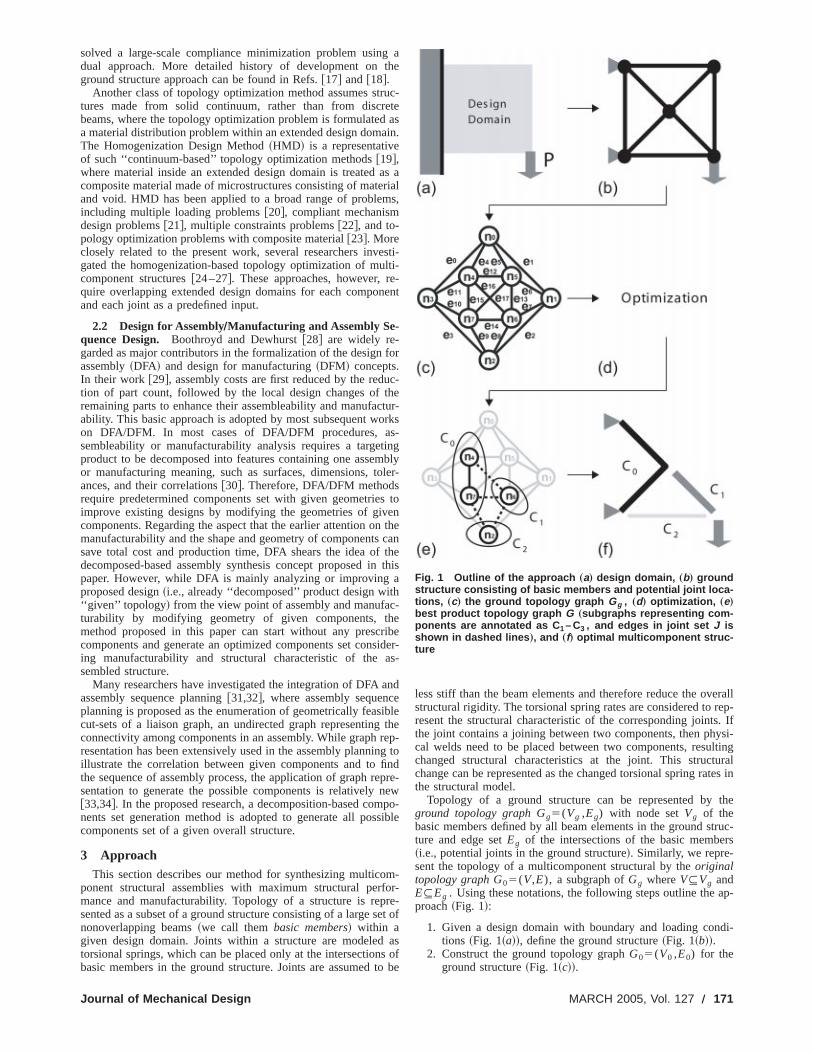
Topology of a ground structure can be represented byground topology graph Gg5(Vg ,Eg) with node setVg of thebasic members defined by all beam elements in the ground sture and edge setEg of the intersections of the basic membe~i.e., potential joints in the ground structure!. Similarly, we repre-sent the topology of a multicomponent structural by theoriginaltopology graph G05(V,E), a subgraph ofGg whereV#Vg andE#Eg . Using these notations, the following steps outline theproach~Fig. 1!:
1. Given a design domain with boundary and loading contions ~Fig. 1~a!!, define the ground structure~Fig. 1~b!!.
2. Construct the ground topology graphG05(V0 ,E0) for theground structure~Fig. 1~c!!.
Fig. 1 Outline of the approach „a… design domain, „b… groundstructure consisting of basic members and potential joint loca-tions, „c… the ground topology graph Gg , „d… optimization, „e…best product topology graph G „subgraphs representing com-ponents are annotated as C 1 – C3 , and edges in joint set J isshown in dashed lines …, and „f… optimal multicomponent struc-ture
MARCH 2005, Vol. 127 Õ 171
o
r
b
n
t
n
y
tu
a
e
int
d
t a
c-the
nd-two-D
3. Using an optimization algorithm~Fig. 1~d!!, obtain the prod-uct topology graphG5(V,E,J) that gives the best structuraperformance and manufacturability~Fig. 1~e!!.
4. Construct the multicomponent structure corresponding tG~Fig. 1~f!!.
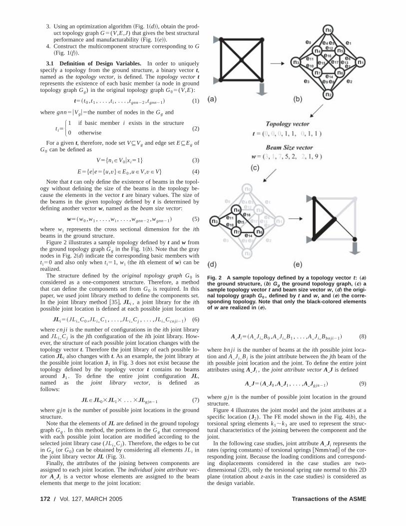
3.1 Definition of Design Variables. In order to uniquelyspecify a topology from the ground structure, a binary vectot,named as thetopology vector, is defined. Thetopology vectortrepresents the existence of each basic member~a node in groundtopology graphGg) in the original topology graphG05(V,E):
t5~ t0 ,t1 , . . . ,t i , . . . ,tgnn22 ,tgnn21! (1)
wheregnn5uVgu5the number of nodes in theGg and
t i5H 1 if basic memberi exists in the structure
0 otherwise(2)
For a givent, therefore, node setV#Vg and edge setE#Eg ofG0 can be defined as
V5$niPV0uxi51% (3)
E5$eue5$u,v%PE0 ,uPV,vPV% (4)
Note thatt can only define the existence of beams in the topogy without defining the size of the beams in the topologycause the elements in the vectort are binary values. The size othe beams in the given topology defined byt is determined bydefining another vectorw, named as thebeam size vector:
w5~w0 ,w1 , . . . ,wi , . . . ,wgnn22 ,wgnn21! (5)
where wi represents the cross sectional dimension for theithbeams in the ground structure.
Figure 2 illustrates a sample topology defined byt andw fromthe ground topology graphGg in the Fig. 1~b!. Note that the graynodes in Fig. 2~d! indicate the corresponding basic members wt i50 and also only whent i51, wi ~the ith element ofw! can berealized.
The structure defined by theoriginal topology graph G0 isconsidered as a one-component structure. Therefore, a methat can define the components set fromG0 is required. In thispaper, we used joint library method to define the componentsIn the joint library method@35#, JL i , a joint library for theithpossible joint location is defined at each possible joint locatio
JL i5~JLiIC0 ,JLiIC1 , . . . ,JLiICj , . . . ,JLiICcn ji21! (6)
wherecn j i is the number of configurations in theith joint libraryand JLiICj is the jth configuration of theith joint library. How-ever, the structure of each possible joint location changes withtopology vectort. Therefore the joint library of each possible locationJL i also changes witht. As an example, the joint library athe possible joint locationJ1 in Fig. 3 does not exist because thtopology defined by the topology vectort contains no beamsaround J1 . To define the entire joint configurationJL,named as the joint library vector, is defined asfollows:
JLPJL03JL13 . . . 3JLg jn21 (7)
whereg jn is the number of possible joint locations in the groustructure.
Note that the elements ofJL are defined in the ground topologgraphGg . In this method, the portions in theGg that correspondwith each possible joint location are modified according toselected joint library case (JLiICj ). Therefore, the edges to be cin Gg ~or G0) can be obtained by considering all elementsJLi inthe joint library vectorJL ~Fig. 3!.
Finally, the attributes of the joining between componentsassigned to each joint location. Theindividual joint attribute vec-tor AIJi is a vector whose elements are assigned to the belements that merge to the joint location:
172 Õ Vol. 127, MARCH 2005
l
ol-e-f
ith
thod
set.
the-
e
d
het
re
am
AIJi5~AIJiIB0 ,AIJiIB1 , . . . ,AIJiIBbn ji21! (8)
wherebn ji is the number of beams at theith possible joint loca-tion andAIJiIBj is the joint attribute between thejth beam of theith possible joint location and the joint. To define the entire joattributes usingAIJi , the joint attribute vectorAIJ is defined
AIJ5~AIJ0 ,AIJ1 , . . . ,AIJg jn21! (9)
whereg jn is the number of possible joint location in the grounstructure.
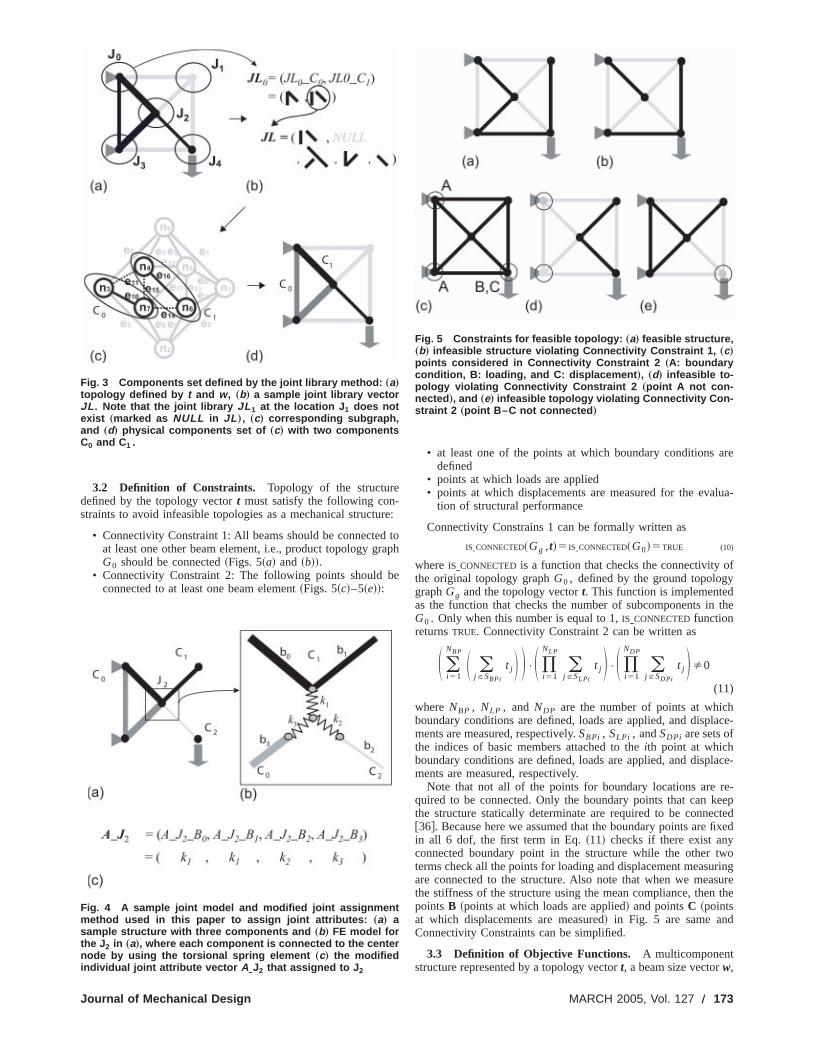
Figure 4 illustrates the joint model and the joint attributes aspecific location (J2). The FE model shown in the Fig. 4~b!, thetorsional spring elementsk1;k3 are used to represent the strutural characteristics of the joining between the component andjoint.
In the following case studies, joint attributeAIJi represents therates~spring constants! of torsional springs@Nmm/rad# of the cor-responding joint. Because the loading conditions and correspoing displacements considered in the case studies aredimensional~2D!, only the torsional spring rate normal to this 2plane ~rotation aboutz-axis in the case studies! is considered asthe design variable.
Fig. 2 A sample topology defined by a topology vector t : „a…the ground structure, „b… Gg the ground topology graph, „c… asample topology vector t and beam size vector w , „d… the origi-nal topology graph G0 , defined by t and w, and „e… the corre-sponding topology. Note that only the black-colored elementsof w are realized in „e….
Transactions of the ASME
are
lua-
f
the
ace-
ace-
e-eepctedfixed
woringsurethe
3.2 Definition of Constraints. Topology of the structuredefined by the topology vectort must satisfy the following con-straints to avoid infeasible topologies as a mechanical structu
• Connectivity Constraint 1: All beams should be connectedat least one other beam element, i.e., product topology grG0 should be connected~Figs. 5~a! and ~b!!.
• Connectivity Constraint 2: The following points should bconnected to at least one beam element~Figs. 5~c!–5~e!!:
Fig. 3 Components set defined by the joint library method: „a…topology defined by t and w, „b… a sample joint library vectorJL . Note that the joint library JL 1 at the location J 1 does notexist „marked as NULL in JL …, „c… corresponding subgraph,and „d… physical components set of „c… with two componentsC0 and C1 .
Fig. 4 A sample joint model and modified joint assignmentmethod used in this paper to assign joint attributes: „a… asample structure with three components and „b… FE model forthe J 2 in „a…, where each component is connected to the centernode by using the torsional spring element „c… the modifiedindividual joint attribute vector AOJ2 that assigned to J 2
Journal of Mechanical Design
re:
toaph
e
• at least one of the points at which boundary conditionsdefined
• points at which loads are applied• points at which displacements are measured for the eva
tion of structural performance
Connectivity Constrains 1 can be formally written as
ISICONNECTED~Gg ,t!5 ISICONNECTED~G0!5TRUE (10)
whereISICONNECTEDis a function that checks the connectivity othe original topology graphG0 , defined by the ground topologygraphGg and the topology vectort. This function is implementedas the function that checks the number of subcomponents inG0 . Only when this number is equal to 1,ISICONNECTEDfunctionreturnsTRUE. Connectivity Constraint 2 can be written as
S (i 51
NBP S (j PSBPi
t j D D •S )i 51
NLP
(j PSLPi
t j D •S )i 51
NDP
(j PSDPi
t j D Þ0
(11)
where NBP , NLP , and NDP are the number of points at whichboundary conditions are defined, loads are applied, and displments are measured, respectively.SBPi , SLPi , andSDPi are sets ofthe indices of basic members attached to theith point at whichboundary conditions are defined, loads are applied, and displments are measured, respectively.
Note that not all of the points for boundary locations are rquired to be connected. Only the boundary points that can kthe structure statically determinate are required to be conne@36#. Because here we assumed that the boundary points arein all 6 dof, the first term in Eq.~11! checks if there exist anyconnected boundary point in the structure while the other tterms check all the points for loading and displacement measuare connected to the structure. Also note that when we meathe stiffness of the structure using the mean compliance, thenpointsB ~points at which loads are applied! and pointsC ~pointsat which displacements are measured! in Fig. 5 are same andConnectivity Constraints can be simplified.
3.3 Definition of Objective Functions. A multicomponentstructure represented by a topology vectort, a beam size vectorw,
Fig. 5 Constraints for feasible topology: „a… feasible structure,„b… infeasible structure violating Connectivity Constraint 1, „c…points considered in Connectivity Constraint 2 „A: boundarycondition, B: loading, and C: displacement …, „d… infeasible to-pology violating Connectivity Constraint 2 „point A not con-nected …, and „e… infeasible topology violating Connectivity Con-straint 2 „point B–C not connected …
MARCH 2005, Vol. 127 Õ 173

g
r
t
r
n
e
i
onr
u
a
-
ts
spoting
thetelyst
the joint library vectorJL for the components set, and finallyjoint attribute vectorAIJ is evaluated according to the followinfour criteria:~i! stiffness of the structure,~ii ! weight of the struc-ture, ~iii ! manufacturability of each component in the structuand ~iv! numbers of joints~torsional springs! in the structure.
Stiffness of a structure can be measured as the negative ocompliance in the structure
f stiffness5stiffness52COMPLIANCE~Gg ,t,w,JL,AIJ! (12)
whereCOMPLIANCE is a function that returns the compliance in thmulticomponents structure, using finite element analyses. Tfunction is composed of three modules:~i! FE model generatormodulegenerating a FE input model composed of beam andsional spring elements. Existences of beam elements are dmined by topology vectort and their cross sectional properties adetermined using the beam size vectorw. Torsional spring ele-ments are placed at all possible joint locations and their sprates are determined by the joint attribute vectorAIJ. ~ii ! FEanalysis moduleperforming FE analysis.~iii ! Compliance evalu-ating modulecollecting the displacements at the given loadipoints and evaluating complianceC using following equation:
C512$ f %T$u% (13)
where$f% is the vector of the external loads and$u% is the globalvector of the nodal displacements calculated from the FE analy
Weight of a structure can be calculated as the inner productopology vectort and the beam weight vectorwb of the weights ofthe basic members in the ground structure
f weight5wb"t (14)
where the vectorwb is defined as
wb5~wb 0,wb 1, . . . ,wb i , . . . ,wb gnn22 ,wb gnn21! (15)
Here,gnn5uVgu andwb i5weight of ith basic member definedby the beam size vectorw. For an example, ifwi ~the ith elementof beam size vectorw! defines the diameter of the cylindricabeam cross section and the density of the beam isr, then wb i52pwil ir. Note that l i indicates the length of theith beamelement.
Estimating manufacturability will require specific approachfor each manufacturing process. In this paper, manufacturabof components~to be maximized! is evaluated considering thtotal cost of producing components in the structure~to be mini-mized! represented by a product topology graph. It is assumedcomponents are made from sheet metals working, whose coestimated as the cost of stamping and blanking dies. The die cconsist of die set cost and die machining cost, which are functof die usable areaAu and shearing perimeterP, respectively@29#.For each component,Au is approximated as the convex hull areof given component andP is calculated as the outer perimeterthe component~Fig. 6~c!!. Hence, larger size of the componeresults in higher value ofAu requiring larger die set with highecost. Also, complex geometry of component increases theP valueaccompanied by higher die machining cost. The following eqtion is used to calculate entire manufacturability of a structure
f manufacturability52total manufacturing cost5
2(i 51
cn
DIECOSTS~ i ,SubGi ! (16)
where cn is the number of the components~5number of subgraphs defined byG0 and JL! and SubGi is the ith subgraphdefined byG0 andJL. Finally, DIECOSTS is the function that cal-culates the stamping die cost ofith component and is defined afollows:
DIECOSTS~ i ,SubGi!5COSTAu@Au~SubGi !#
1COSTP@P~SubGi !# (17)
174 Õ Vol. 127, MARCH 2005
a
e,
f the
ehis
or-eter-re
ing
g
sis.t of
l
esility
thest isostsons
aft
a-:
s
whereAu(SubGi) and P(SubGi) calculate the die usable areAu and the shearing parameterP of the ith component defined bysubgraphSubGi . COSTAu and COSTp are the functions than convert Au and P into the cost. Qualitatively, maximizingf manufacturabilitywould result in a structure consisting of componenin smaller sizes and in simpler geometries.
Components at each joint are assumed to be joined withwelds which are done one by one. Since the cost of spot weldfor a structure is proportional to the number of weld spots instructure and the number of weld spots in a joint is approximaproportional to the torsional stiffness of the joint; the welding cois estimated by the sum of the rates of torsional springs@Nm/rad#in the finite element model of the structure
f assembleability52total assembly cost
52(i 51
g jn
COSTRSW@SWELD~ i ,G0 ,JL,AIJ!#
52(i 51
g jn
COSTRSW@WSRATE3SRATE~ i ,G0 ,JL,AIJ!#
(18)
Fig. 6 Manufacturability calculation considering sheet metalworking: „a… a beam component defined, „b… correspondingsheet metal components to be joined into the beam componentdefined in „a…, and „c… die useable area Au calculated from theconvex hull area and shearing parameter P for „b…
Transactions of the ASME
s
e
f
h,
ee
r
s
ame
whereG0 is the original topology graph.JL is the joint libraryvector and AIJ is the joint attribute vector. FunctionSWELD( i ,G0 ,JL,AIJ) returns the total number of welds at theithpossible joint location andCOSTRSWfunction calculates the cost oResistance Spot Welding procedures by using the number ofwelds. Finally,g jn is the total number of possible joint location
In summary, the multiobjective optimization problem to bsolved can be stated as follows:
Maximize $ f stiffness,2 f weight, f manufacturability, f assembleability%
Subject to Connectivity Constraint 1 and 2 defined as
Eqs. ~10! and~11!
(19)3.4 Optimization Algorithm. Due to the multiobjective
formulation~as opposed to, e.g., weighted sum of multiple objtives! and the complexity of the underlying graph partitioninproblem @37#, the above optimization problem is solved usingmodified version of NSGA-II@4,5#, whose basic steps@5# areoutlined below:
1. Create a populationP of n chromosomes~an encoded rep-resentation of design variables! and evaluate their values oobjective functions.
2. Rank each chromosomec in P according to the number oother chromosomes dominatingc in Pareto sense~rank 0 isPareto optimal!. Store the chromosomes with rank 0 into sO. Also, create an empty subpopulationQ.
3. Select two chromosomesci and cj in P with probabilityproportional ton-rank(ci) andn-rank(cj ).
4. Crossoverci and cj to generate two new chromosomesci8andcj8 with a certain high probability.
5. Mutateci8 andcj8 with a certain low probability.6. Evaluate the objective function values ofci8 andcj8 and store
themQ. If Q contains less thanm new chromosomes, go to3.
7. Let P←PøQ and emptyQ, Rank each chromosome inPand removem chromosomes with lowest ranks fromP.
8. Update setQ and increment the generation counter. If tgeneration counter has reached a pre-specified numberminate the process and returnO. Otherwise go to 3.
A chromosomec ~an encoded representation of design vaables! used in this study is a simple list of the four desigvariables
c5~ t,w,JL,AIJ! (20)
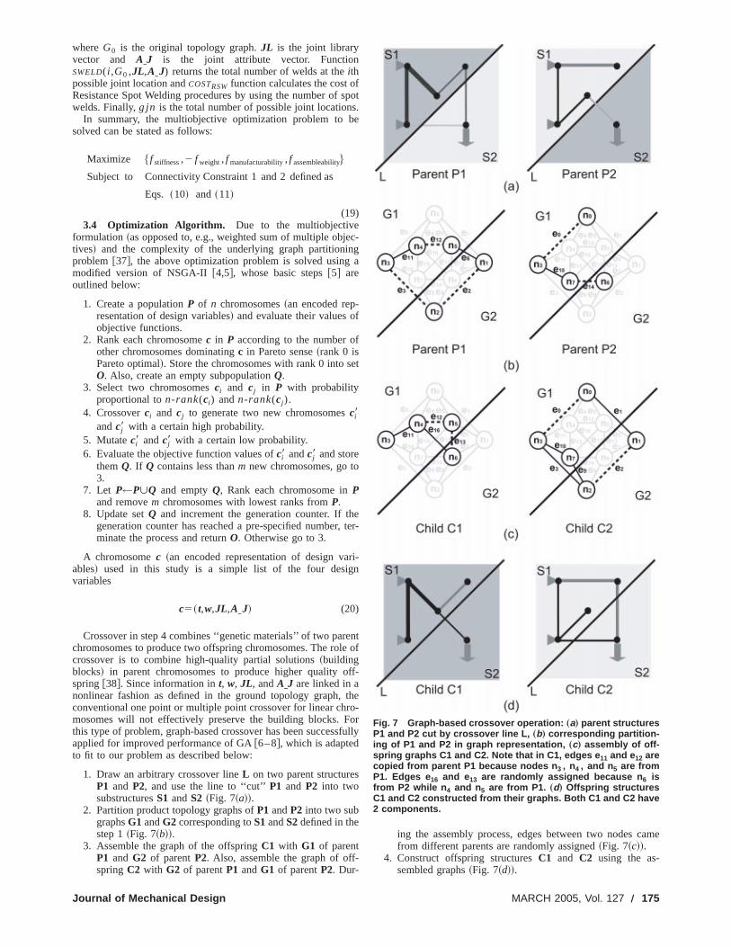
Crossover in step 4 combines ‘‘genetic materials’’ of two parchromosomes to produce two offspring chromosomes. The rolcrossover is to combine high-quality partial solutions~buildingblocks! in parent chromosomes to produce higher quality ospring@38#. Since information int, w, JL, andAIJ are linked in anonlinear fashion as defined in the ground topology graph,conventional one point or multiple point crossover for linear chmosomes will not effectively preserve the building blocks. Fthis type of problem, graph-based crossover has been succesapplied for improved performance of GA@6–8#, which is adaptedto fit to our problem as described below:
1. Draw an arbitrary crossover lineL on two parent structuresP1 and P2, and use the line to ‘‘cut’’P1 and P2 into twosubstructuresS1 andS2 ~Fig. 7~a!!.
2. Partition product topology graphs ofP1 andP2 into two subgraphsG1 andG2 corresponding toS1andS2defined in thestep 1~Fig. 7~b!!.
3. Assemble the graph of the offspringC1 with G1 of parentP1 and G2 of parentP2. Also, assemble the graph of offspringC2 with G2 of parentP1 andG1 of parentP2. Dur-
Journal of Mechanical Design
fspot.e
c-ga
f
et
eter-
ri-n
ntof
ff-
theo-orfully
-
ing the assembly process, edges between two nodes cfrom different parents are randomly assigned~Fig. 7~c!!.
4. Construct offspring structuresC1 and C2 using the as-sembled graphs~Fig. 7~d!!.
Fig. 7 Graph-based crossover operation: „a… parent structuresP1 and P2 cut by crossover line L, „b… corresponding partition-ing of P1 and P2 in graph representation, „c… assembly of off-spring graphs C1 and C2. Note that in C1, edges e 11 and e12 arecopied from parent P1 because nodes n 3 , n4 , and n 5 are fromP1. Edges e 16 and e13 are randomly assigned because n 6 isfrom P2 while n 4 and n 5 are from P1. „d… Offspring structuresC1 and C2 constructed from their graphs. Both C1 and C2 have2 components.
MARCH 2005, Vol. 127 Õ 175
176 Õ Vol. 127
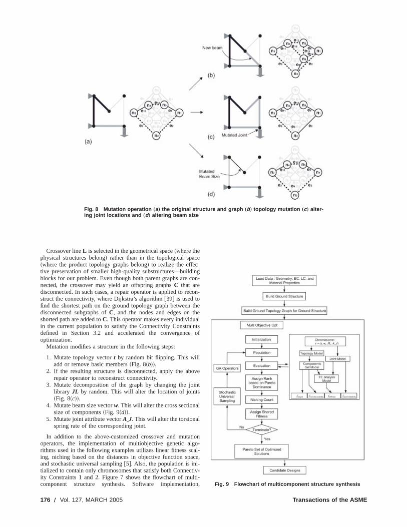
Fig. 8 Mutation operation „a… the original structure and graph „b… topology mutation „c… alter-ing joint locations and „d… altering beam size
i
h
n
o
t
a
li
Crossover lineL is selected in the geometrical space~where thephysical structures belong! rather than in the topological spac~where the product topology graphs belong! to realize the effec-tive preservation of smaller high-quality substructures—buildblocks for our problem. Even though both parent graphs are cnected, the crossover may yield an offspring graphsC that aredisconnected. In such cases, a repair operator is applied to restruct the connectivity, where Dijkstra’s algorithm@39# is used tofind the shortest path on the ground topology graph betweendisconnected subgraphs ofC, and the nodes and edges on tshorted path are added toC. This operator makes every individuain the current population to satisfy the Connectivity Constraidefined in Section 3.2 and accelerated the convergenceoptimization.
Mutation modifies a structure in the following steps:
1. Mutate topology vectort by random bit flipping. This willadd or remove basic members~Fig. 8~b!!.
2. If the resulting structure is disconnected, apply the abrepair operator to reconstruct connectivity.
3. Mutate decomposition of the graph by changing the jolibrary JL by random. This will alter the location of joints~Fig. 8~c!!.
4. Mutate beam size vectorw. This will alter the cross sectionasize of components~Fig. 9~d!!.
5. Mutate joint attribute vectorAIJ. This will alter the torsionalspring rate of the corresponding joint.
In addition to the above-customized crossover and mutaoperators, the implementation of multiobjective genetic algrithms used in the following examples utilizes linear fitness scing, niching based on the distances in objective function spand stochastic universal sampling@5#. Also, the population is ini-tialized to contain only chromosomes that satisfy both Connecity Constraints 1 and 2. Figure 7 shows the flowchart of mucomponent structure synthesis. Software implementat
, MARCH 2005
e
ngon-
con-
theeltsof
ve
int
l
iono-al-ce,
tiv-ti-on, Fig. 9 Flowchart of multicomponent structure synthesis
Transactions of the ASME
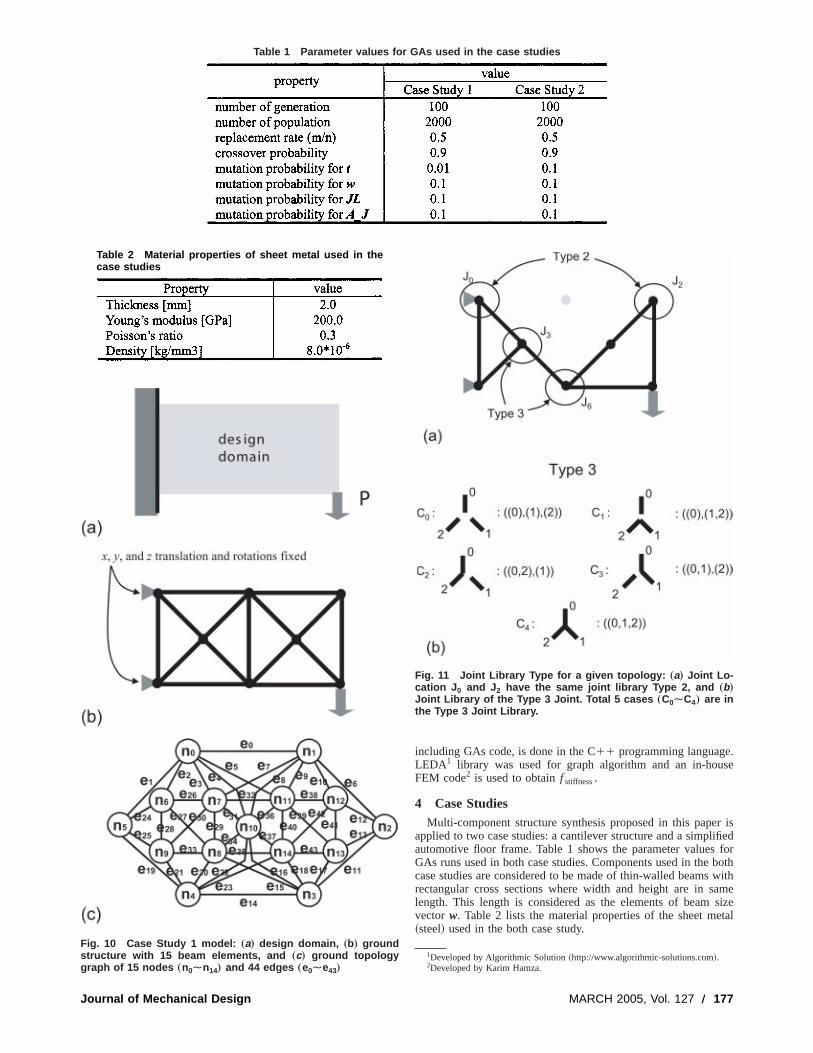
Table 1 Parameter values for GAs used in the case studies
Journal of Mechanical
.se
r isifiedforbothwith
amesizetal
Fig. 10 Case Study 1 model: „a… design domain, „b… groundstructure with 15 beam elements, and „c… ground topologygraph of 15 nodes „n0Èn14… and 44 edges „e0Èe43…
Table 2 Material properties of sheet metal used in thecase studies
Design
including GAs code, is done in the C11 programming languageLEDA1 library was used for graph algorithm and an in-houFEM code2 is used to obtainf stiffness.
4 Case StudiesMulti-component structure synthesis proposed in this pape
applied to two case studies: a cantilever structure and a simplautomotive floor frame. Table 1 shows the parameter valuesGAs runs used in both case studies. Components used in thecase studies are considered to be made of thin-walled beamsrectangular cross sections where width and height are in slength. This length is considered as the elements of beamvector w. Table 2 lists the material properties of the sheet me~steel! used in the both case study.
1Developed by Algorithmic Solution~http://www.algorithmic-solutions.com!.2Developed by Karim Hamza.
Fig. 11 Joint Library Type for a given topology: „a… Joint Lo-cation J 0 and J 2 have the same joint library Type 2, and „b…Joint Library of the Type 3 Joint. Total 5 cases „C0ÈC4… are inthe Type 3 Joint Library.
MARCH 2005, Vol. 127 Õ 177
c
ei
al11
enthereca-
)
not
ve
onlyele-
om
ns
hatthetion
4.1 Case Study 1: Cantilever Structure. For the first casestudy, a cantilever structure is modeled as a design domain in10~a!, with length 200 mm and height 100 mm. The left sidethe domain is fixed on the wall and a vertical loadP ~5100 @N#!is applied at the lower right corner of the domain. The displament is measured at the loading point to calculate the stiffnesthe structure and used to calculate the compliance. Figure 1~b!shows the ground structure with 15 nonoverlapping beamments, each of which are regarded as a basic member. F10~c! shows the ground topology graph of the ground structureFig. 10~b!, containing 15 nodes and 44 edges.
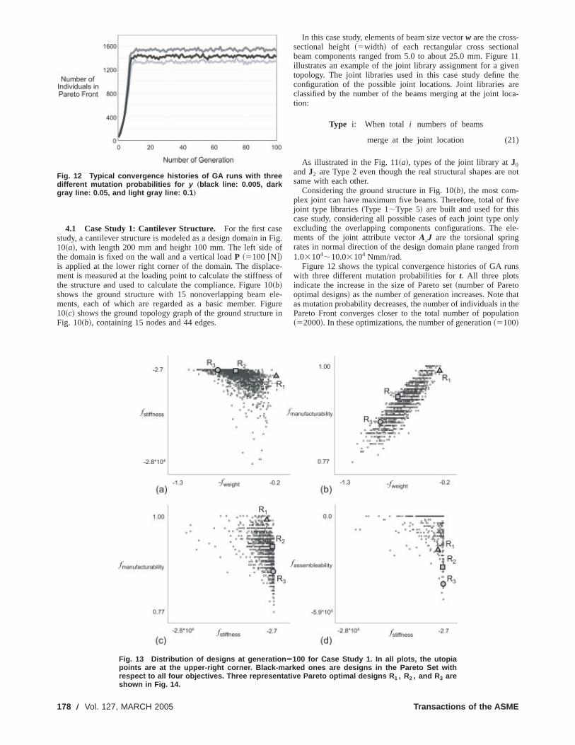
Fig. 12 Typical convergence histories of GA runs with threedifferent mutation probabilities for y „black line: 0.005, darkgray line: 0.05, and light gray line: 0.1 …
178 Õ Vol. 127, MARCH 2005
Fig.of
e-s of0le-
gurein
In this case study, elements of beam size vectorw are the cross-sectional height~5width! of each rectangular cross sectionbeam components ranged from 5.0 to about 25.0 mm. Figureillustrates an example of the joint library assignment for a givtopology. The joint libraries used in this case study defineconfiguration of the possible joint locations. Joint libraries aclassified by the number of the beams merging at the joint lotion:
Type i: When total i numbers of beams
merge at the joint location (21
As illustrated in the Fig. 11~a!, types of the joint library atJ0andJ2 are Type 2 even though the real structural shapes aresame with each other.
Considering the ground structure in Fig. 10~b!, the most com-plex joint can have maximum five beams. Therefore, total of fijoint type libraries~Type 1;Type 5! are built and used for thiscase study, considering all possible cases of each joint typeexcluding the overlapping components configurations. Thements of the joint attribute vectorAIJ are the torsional springrates in normal direction of the design domain plane ranged fr1.03104;10.03104 Nmm/rad.
Figure 12 shows the typical convergence histories of GA ruwith three different mutation probabilities fort. All three plotsindicate the increase in the size of Pareto set~number of Paretooptimal designs! as the number of generation increases. Note tas mutation probability decreases, the number of individuals inPareto Front converges closer to the total number of popula~52000!. In these optimizations, the number of generation~5100!
Fig. 13 Distribution of designs at generation Ä100 for Case Study 1. In all plots, the utopiapoints are at the upper-right corner. Black-marked ones are designs in the Pareto Set withrespect to all four objectives. Three representative Pareto optimal designs R 1 , R2 , and R3 areshown in Fig. 14.
Transactions of the ASME
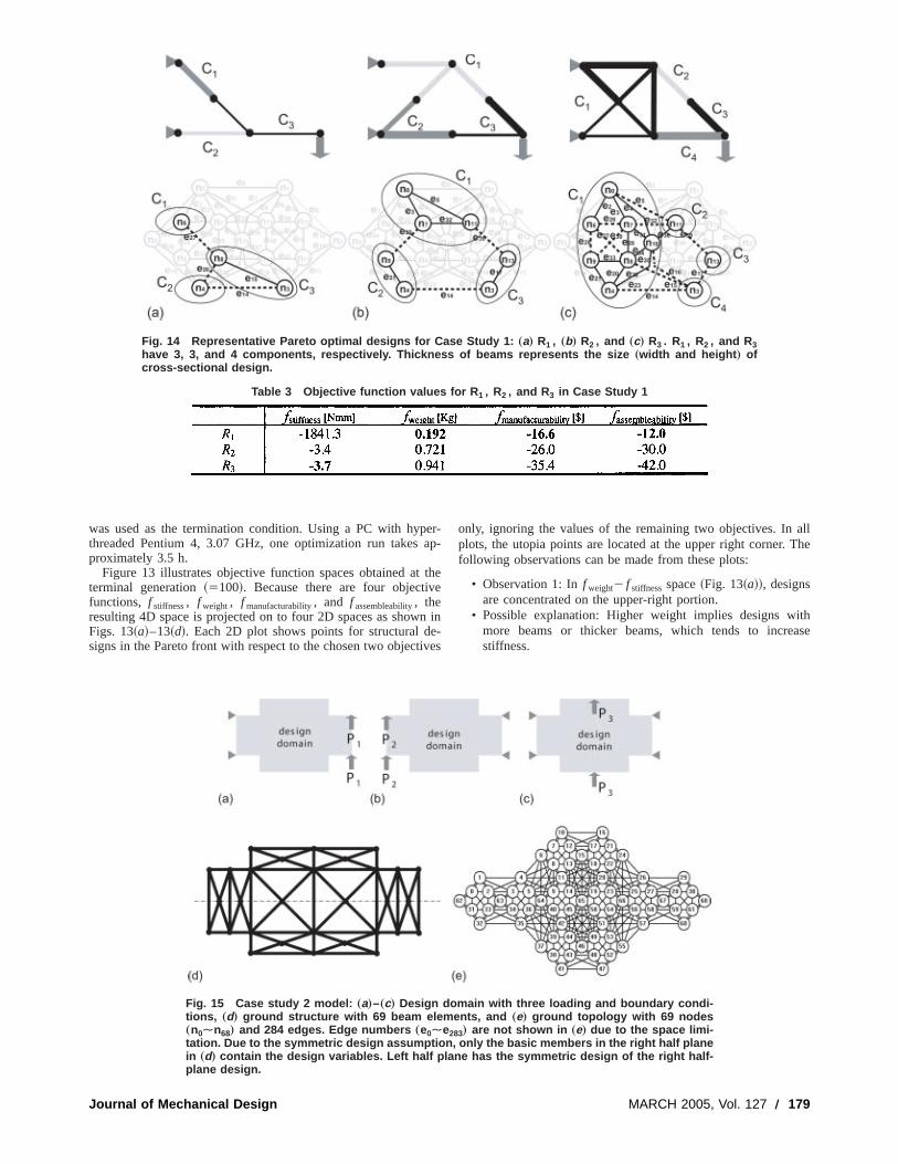
Journal
Fig. 14 Representative Pareto optimal designs for Case Study 1: „a… R1 , „b… R2 , and „c… R3 . R1 , R2 , and R3have 3, 3, and 4 components, respectively. Thickness of beams represents the size „width and height … ofcross-sectional design.
Table 3 Objective function values for R 1 , R2 , and R3 in Case Study 1
ei
allThe
ithase
was used as the termination condition. Using a PC with hypthreaded Pentium 4, 3.07 GHz, one optimization run takesproximately 3.5 h.
Figure 13 illustrates objective function spaces obtained atterminal generation~5100!. Because there are four objectivfunctions, f stiffness, f weight, f manufacturability, and f assembleability, theresulting 4D space is projected on to four 2D spaces as showFigs. 13~a!–13~d!. Each 2D plot shows points for structural dsigns in the Pareto front with respect to the chosen two object
of Mechanical Design
er-ap-
thee
n in-ves
only, ignoring the values of the remaining two objectives. Inplots, the utopia points are located at the upper right corner.following observations can be made from these plots:
• Observation 1: Inf weight2 f stiffnessspace~Fig. 13~a!!, designsare concentrated on the upper-right portion.
• Possible explanation: Higher weight implies designs wmore beams or thicker beams, which tends to increstiffness.
Fig. 15 Case study 2 model: „a…–„c… Design domain with three loading and boundary condi-tions, „d… ground structure with 69 beam elements, and „e… ground topology with 69 nodes„n0Èn68… and 284 edges. Edge numbers „e0Èe283… are not shown in „e… due to the space limi-tation. Due to the symmetric design assumption, only the basic members in the right half planein „d… contain the design variables. Left half plane has the symmetric design of the right half-plane design.
MARCH 2005, Vol. 127 Õ 179
f
iraea
e
ai
u
hhl
g
f
thehis
ds a
t to
ori-t-ons
• Observation 2: f weight2 f manufacturability space ~Fig. 13~b!!shows a linear trend between the total weight and manuturing cost.
• Possible explanation: Two elements that determf manufacturability@die usable area (Au) and shearing perimete~P!# are highly related to thef weight because as a design’s totweight increases by having more number of beams, at lone of Au or P will be increased. As a result, higher totweight implies lower manufacturability~lessAu andP!.
• Observation 3: Designs with lower stiffness show highmanufacturability~Fig. 13~c!!.
• Possible explanation: Higher manufacturability implismaller components~smallerAu), which would require morejoints, which, in turn, tends to reduce stiffness.
Three representative Pareto optimal designs, annotated asR1 ,R2 , andR3 in Fig. 13, are shown in Fig. 14, and their objectivfunction values are listed in the Table 3. The geometry of estructure exhibits its unique characteristics allowing the followinterpretations:
• StructureR1 ~Fig. 14~a!! is a very light structure with threesimple components connected by two joints. This structshows good manufacturability by having small numbersimple-shaped components.
• StructureR2 ~Fig. 11~b!! shows balanced performances in tmost objectives. The structure is fairly stiff thanks to tclever arrangement of beams~including a triangular internastructure! while most components are relatively small sizeThis triangular shape seems to impose mostly axial loadineach beam, thereby avoiding bending of joints.
• StructureR3 ~Fig. 11~c!! has four components and is the stifest among the three structures. It contains the componentC1 ,which is more complex and larger than the components ofR1andR2 . By having numbers of internal triangular structure
180 Õ Vol. 127, MARCH 2005
ac-
ne
lastl
er
s
ech
ng
reof
ee
d.in
-
s,
this component seems to help in increasing the stiffness ofstructure. However, due to the size and complexity of tcomponent, entire manufacturability is relatively low.
4.2 Case Study 2: Simplified Automotive Floor Frame Un-der Multiple Loadings. For the second case study, a simplifieautomotive floor frame under multiple loadings is modeled adesign domain in Figs. 15~a!–15~c!, with length 3000 mm andwidth 1600 mm seen from the above. The structure is subjecthe following three loading cases:
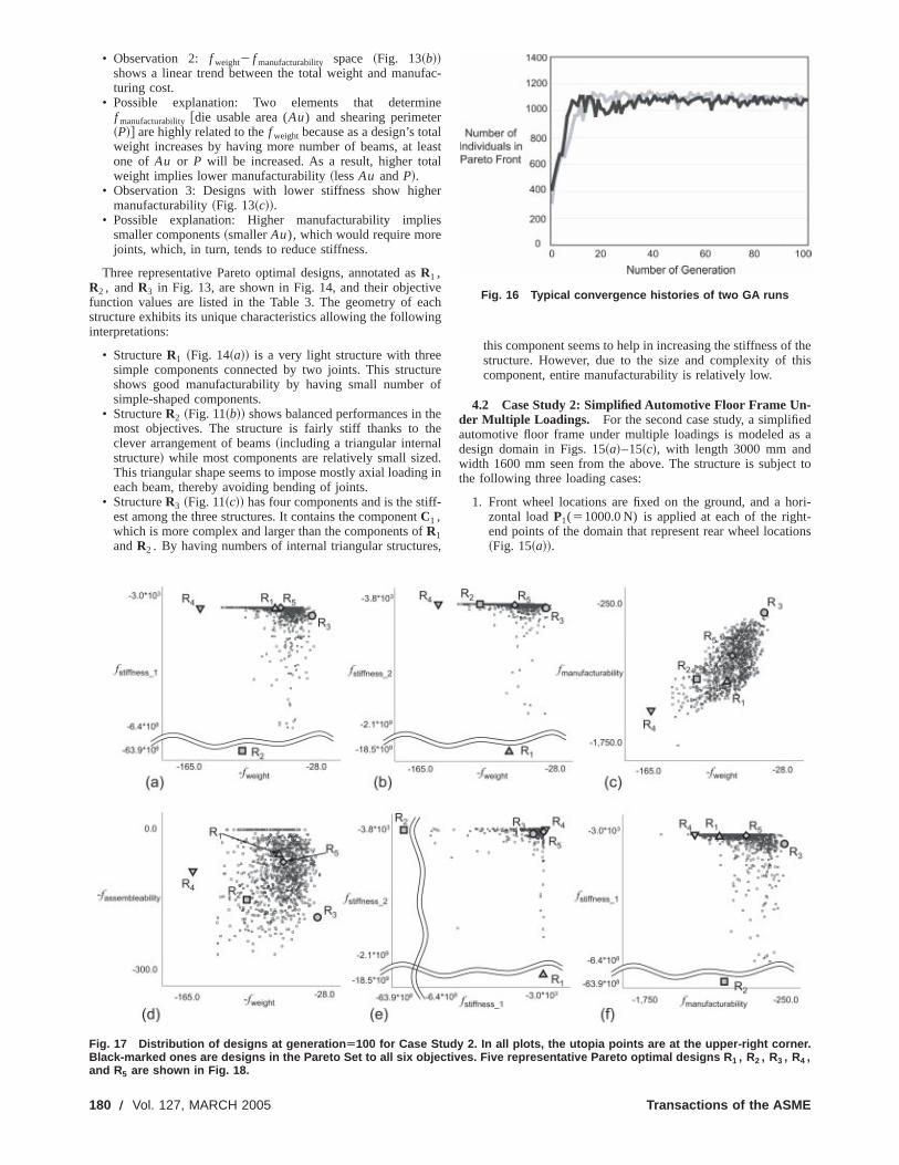
1. Front wheel locations are fixed on the ground, and a hzontal loadP1(51000.0 N) is applied at each of the righend points of the domain that represent rear wheel locati~Fig. 15~a!!.
Fig. 16 Typical convergence histories of two GA runs
Fig. 17 Distribution of designs at generation Ä100 for Case Study 2. In all plots, the utopia points are at the upper-right corner.Black-marked ones are designs in the Pareto Set to all six objectives. Five representative Pareto optimal designs R 1 , R2 , R3 , R4 ,and R5 are shown in Fig. 18.
Transactions of the ASME
Journal of Mech
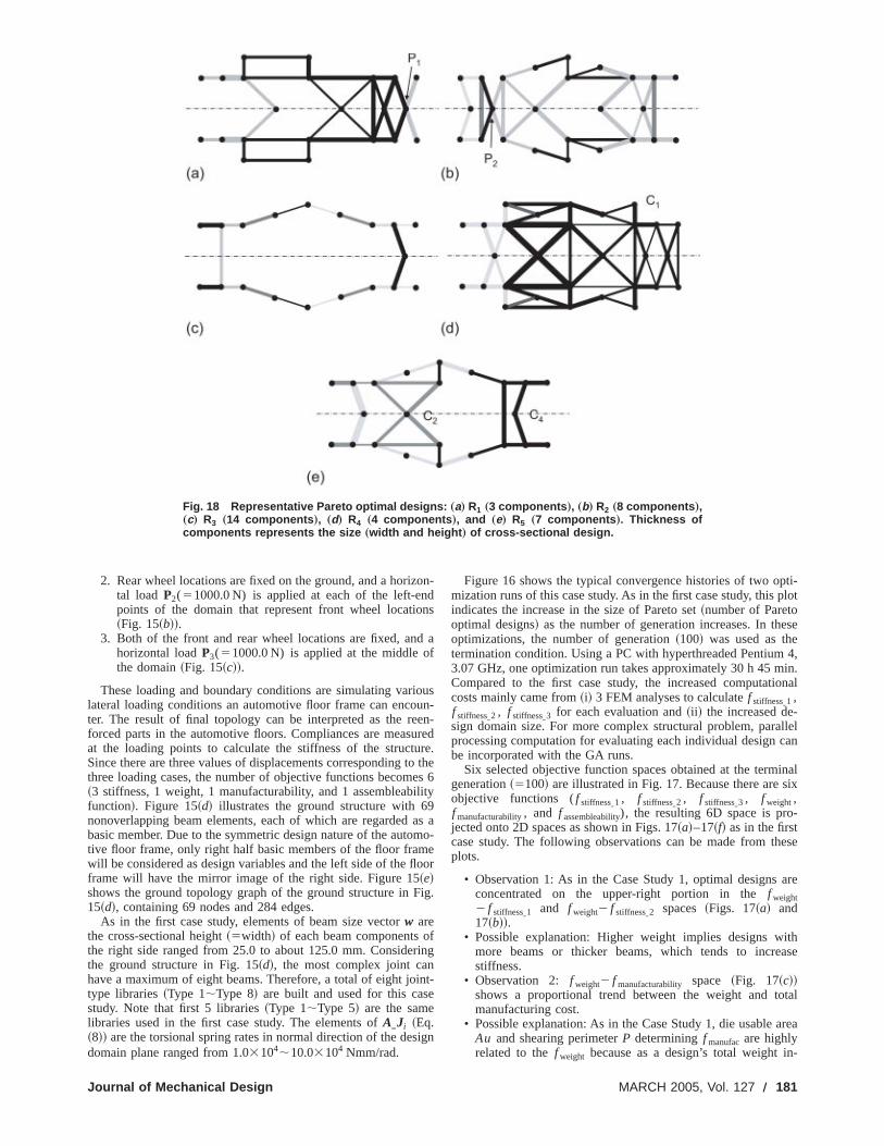
Fig. 18 Representative Pareto optimal designs: „a… R1 „3 components …, „b… R2 „8 components …,„c… R3 „14 components …, „d… R4 „4 components …, and „e… R5 „7 components …. Thickness ofcomponents represents the size „width and height … of cross-sectional design.
d
o
u
o
i9
r
ie
pti-plot
ese
4,in.onal
llelcan
inalsix
-
ese
are
ithase
tal
area
n-
2. Rear wheel locations are fixed on the ground, and a horiztal load P2(51000.0 N) is applied at each of the left-enpoints of the domain that represent front wheel locatio~Fig. 15~b!!.
3. Both of the front and rear wheel locations are fixed, anhorizontal loadP3(51000.0 N) is applied at the middle othe domain~Fig. 15~c!!.
These loading and boundary conditions are simulating varilateral loading conditions an automotive floor frame can encoter. The result of final topology can be interpreted as the reforced parts in the automotive floors. Compliances are measat the loading points to calculate the stiffness of the structuSince there are three values of displacements corresponding tthree loading cases, the number of objective functions becom~3 stiffness, 1 weight, 1 manufacturability, and 1 assembleabfunction!. Figure 15~d! illustrates the ground structure with 6nonoverlapping beam elements, each of which are regardedbasic member. Due to the symmetric design nature of the autotive floor frame, only right half basic members of the floor framwill be considered as design variables and the left side of the flframe will have the mirror image of the right side. Figure 15~e!shows the ground topology graph of the ground structure in F15~d!, containing 69 nodes and 284 edges.
As in the first case study, elements of beam size vectorw arethe cross-sectional height~5width! of each beam components othe right side ranged from 25.0 to about 125.0 mm. Considethe ground structure in Fig. 15~d!, the most complex joint canhave a maximum of eight beams. Therefore, a total of eight jotype libraries~Type 1;Type 8! are built and used for this casstudy. Note that first 5 libraries~Type 1;Type 5! are the samelibraries used in the first case study. The elements ofAIJi ~Eq.~8!! are the torsional spring rates in normal direction of the desdomain plane ranged from 1.03104;10.03104 Nmm/rad.
anical Design
on-dns
af
usun-en-redre.the
es 6lity
as amo-e
oor
ig.
fing
nt-
ign
Figure 16 shows the typical convergence histories of two omization runs of this case study. As in the first case study, thisindicates the increase in the size of Pareto set~number of Paretooptimal designs! as the number of generation increases. In thoptimizations, the number of generation~100! was used as thetermination condition. Using a PC with hyperthreaded Pentium3.07 GHz, one optimization run takes approximately 30 h 45 mCompared to the first case study, the increased computaticosts mainly came from~i! 3 FEM analyses to calculatef stiffnessI1 ,f stiffnessI2 , f stiffnessI3 for each evaluation and~ii ! the increased de-sign domain size. For more complex structural problem, paraprocessing computation for evaluating each individual designbe incorporated with the GA runs.
Six selected objective function spaces obtained at the termgeneration~5100! are illustrated in Fig. 17. Because there areobjective functions (f stiffnessI1 , f stiffnessI2 , f stiffnessI3 , f weight,f manufacturability, and f assembleability), the resulting 6D space is projected onto 2D spaces as shown in Figs. 17~a!–17~f! as in the firstcase study. The following observations can be made from thplots.
• Observation 1: As in the Case Study 1, optimal designsconcentrated on the upper-right portion in thef weight2 f stiffnessI1 and f weight2 f stiffnessI2 spaces~Figs. 17~a! and17~b!!.
• Possible explanation: Higher weight implies designs wmore beams or thicker beams, which tends to increstiffness.
• Observation 2: f weight2 f manufacturability space ~Fig. 17~c!!shows a proportional trend between the weight and tomanufacturing cost.
• Possible explanation: As in the Case Study 1, die usableAu and shearing perimeterP determiningf manufacare highlyrelated to thef weight because as a design’s total weight i
MARCH 2005, Vol. 127 Õ 181
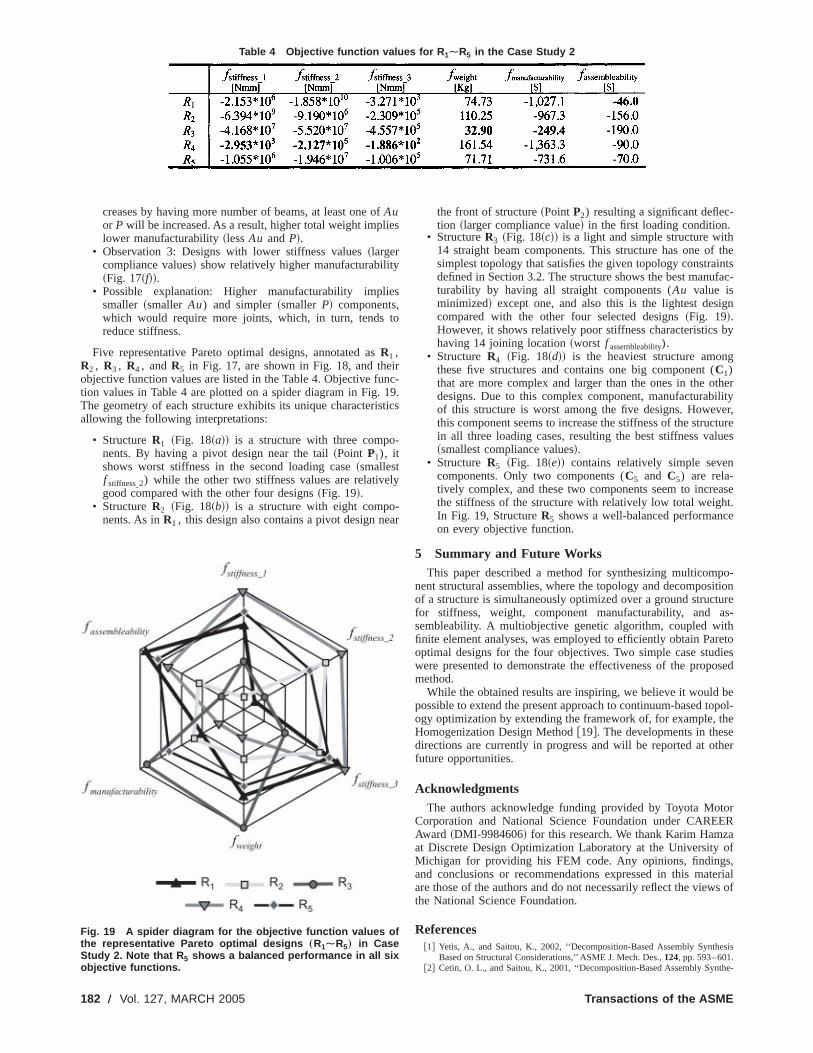
Table 4 Objective function values for R ÈR in the Case Study 2
182 Õ Vol. 127
1 5
fe
y
e
t
in
-
-
theintsfac-
gn
by
g
therilityer,tureues
n
aset.e
po-itiontures-
thretoiesosed
beopol-heeher
torERaof,
erials of
sis
he-
creases by having more number of beams, at least one oAuor P will be increased. As a result, higher total weight implilower manufacturability~lessAu andP!.
• Observation 3: Designs with lower stiffness values~largercompliance values! show relatively higher manufacturabilit~Fig. 17~f!!.
• Possible explanation: Higher manufacturability implismaller ~smaller Au) and simpler~smaller P! components,which would require more joints, which, in turn, tendsreduce stiffness.
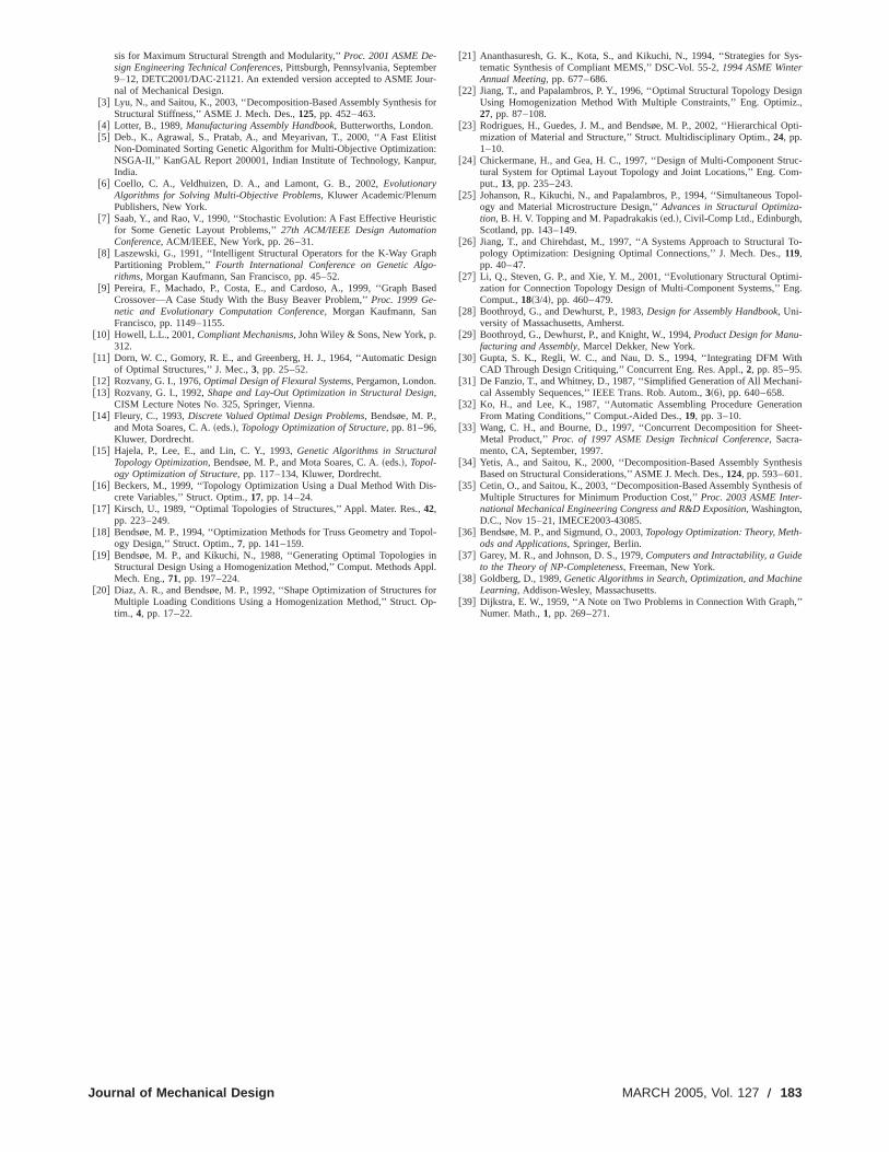
Five representative Pareto optimal designs, annotated asR1 ,R2 , R3 , R4 , andR5 in Fig. 17, are shown in Fig. 18, and theobjective function values are listed in the Table 4. Objective fution values in Table 4 are plotted on a spider diagram in Fig.The geometry of each structure exhibits its unique characterisallowing the following interpretations:
• StructureR1 ~Fig. 18~a!! is a structure with three components. By having a pivot design near the tail~Point P1), itshows worst stiffness in the second loading case~smallestf stiffnessI2) while the other two stiffness values are relativegood compared with the other four designs~Fig. 19!.
• StructureR2 ~Fig. 18~b!! is a structure with eight components. As inR1 , this design also contains a pivot design ne
Fig. 19 A spider diagram for the objective function values ofthe representative Pareto optimal designs „R1ÈR5… in CaseStudy 2. Note that R 5 shows a balanced performance in all sixobjective functions.
, MARCH 2005
s
s
o
rc-
19.tics
-
ly
ar
the front of structure~PointP2) resulting a significant deflection ~larger compliance value! in the first loading condition.
• StructureR3 ~Fig. 18~c!! is a light and simple structure with14 straight beam components. This structure has one ofsimplest topology that satisfies the given topology constradefined in Section 3.2. The structure shows the best manuturability by having all straight components (Au value isminimized! except one, and also this is the lightest desicompared with the other four selected designs~Fig. 19!.However, it shows relatively poor stiffness characteristicshaving 14 joining location~worst f assembleability).
• StructureR4 ~Fig. 18~d!! is the heaviest structure amonthese five structures and contains one big component (C1)that are more complex and larger than the ones in the odesigns. Due to this complex component, manufacturabof this structure is worst among the five designs. Howevthis component seems to increase the stiffness of the strucin all three loading cases, resulting the best stiffness val~smallest compliance values!.
• StructureR5 ~Fig. 18~e!! contains relatively simple sevecomponents. Only two components (C5 and C5) are rela-tively complex, and these two components seem to increthe stiffness of the structure with relatively low total weighIn Fig. 19, StructureR5 shows a well-balanced performancon every objective function.
5 Summary and Future WorksThis paper described a method for synthesizing multicom
nent structural assemblies, where the topology and decomposof a structure is simultaneously optimized over a ground strucfor stiffness, weight, component manufacturability, and asembleability. A multiobjective genetic algorithm, coupled wifinite element analyses, was employed to efficiently obtain Paoptimal designs for the four objectives. Two simple case studwere presented to demonstrate the effectiveness of the propmethod.
While the obtained results are inspiring, we believe it wouldpossible to extend the present approach to continuum-based togy optimization by extending the framework of, for example, tHomogenization Design Method@19#. The developments in thesdirections are currently in progress and will be reported at otfuture opportunities.
AcknowledgmentsThe authors acknowledge funding provided by Toyota Mo
Corporation and National Science Foundation under CAREAward ~DMI-9984606! for this research. We thank Karim Hamzat Discrete Design Optimization Laboratory at the UniversityMichigan for providing his FEM code. Any opinions, findingsand conclusions or recommendations expressed in this matare those of the authors and do not necessarily reflect the viewthe National Science Foundation.
References@1# Yetis, A., and Saitou, K., 2002, ‘‘Decomposition-Based Assembly Synthe
Based on Structural Considerations,’’ ASME J. Mech. Des.,124, pp. 593–601.@2# Cetin, O. L., and Saitou, K., 2001, ‘‘Decomposition-Based Assembly Synt
Transactions of the ASME
eo
in
s
p
a
i
n
s
p
p
ys-
ign.,
pti-
uc-m-
pol-
To-
i-g.
th
i-
ion
et-
sis
is of
e
,’’
sis for Maximum Structural Strength and Modularity,’’Proc. 2001 ASME De-sign Engineering Technical Conferences, Pittsburgh, Pennsylvania, Septemb9–12, DETC2001/DAC-21121. An extended version accepted to ASME Jnal of Mechanical Design.
@3# Lyu, N., and Saitou, K., 2003, ‘‘Decomposition-Based Assembly SynthesisStructural Stiffness,’’ ASME J. Mech. Des.,125, pp. 452–463.
@4# Lotter, B., 1989,Manufacturing Assembly Handbook, Butterworths, London.@5# Deb., K., Agrawal, S., Pratab, A., and Meyarivan, T., 2000, ‘‘A Fast Elit
Non-Dominated Sorting Genetic Algorithm for Multi-Objective OptimizatioNSGA-II,’’ KanGAL Report 200001, Indian Institute of Technology, KanpuIndia.
@6# Coello, C. A., Veldhuizen, D. A., and Lamont, G. B., 2002,EvolutionaryAlgorithms for Solving Multi-Objective Problems, Kluwer Academic/PlenumPublishers, New York.
@7# Saab, Y., and Rao, V., 1990, ‘‘Stochastic Evolution: A Fast Effective Heurifor Some Genetic Layout Problems,’’27th ACM/IEEE Design AutomationConference, ACM/IEEE, New York, pp. 26–31.
@8# Laszewski, G., 1991, ‘‘Intelligent Structural Operators for the K-Way GraPartitioning Problem,’’Fourth International Conference on Genetic Algorithms, Morgan Kaufmann, San Francisco, pp. 45–52.
@9# Pereira, F., Machado, P., Costa, E., and Cardoso, A., 1999, ‘‘Graph BCrossover—A Case Study With the Busy Beaver Problem,’’Proc. 1999 Ge-netic and Evolutionary Computation Conference, Morgan Kaufmann, SanFrancisco, pp. 1149–1155.
@10# Howell, L.L., 2001,Compliant Mechanisms, John Wiley & Sons, New York, p.312.
@11# Dorn, W. C., Gomory, R. E., and Greenberg, H. J., 1964, ‘‘Automatic Desof Optimal Structures,’’ J. Mec.,3, pp. 25–52.
@12# Rozvany, G. I., 1976,Optimal Design of Flexural Systems, Pergamon, London.@13# Rozvany, G. I., 1992,Shape and Lay-Out Optimization in Structural Desig,
CISM Lecture Notes No. 325, Springer, Vienna.@14# Fleury, C., 1993,Discrete Valued Optimal Design Problems, Bendsøe, M. P.,
and Mota Soares, C. A.~eds.!, Topology Optimization of Structure, pp. 81–96,Kluwer, Dordrecht.
@15# Hajela, P., Lee, E., and Lin, C. Y., 1993,Genetic Algorithms in StructuralTopology Optimization, Bendsøe, M. P., and Mota Soares, C. A.~eds.!, Topol-ogy Optimization of Structure, pp. 117–134, Kluwer, Dordrecht.
@16# Beckers, M., 1999, ‘‘Topology Optimization Using a Dual Method With Dicrete Variables,’’ Struct. Optim.,17, pp. 14–24.
@17# Kirsch, U., 1989, ‘‘Optimal Topologies of Structures,’’ Appl. Mater. Res.,42,pp. 223–249.
@18# Bendsøe, M. P., 1994, ‘‘Optimization Methods for Truss Geometry and Toogy Design,’’ Struct. Optim.,7, pp. 141–159.
@19# Bendsøe, M. P., and Kikuchi, N., 1988, ‘‘Generating Optimal TopologiesStructural Design Using a Homogenization Method,’’ Comput. Methods ApMech. Eng.,71, pp. 197–224.
@20# Diaz, A. R., and Bendsøe, M. P., 1992, ‘‘Shape Optimization of StructuresMultiple Loading Conditions Using a Homogenization Method,’’ Struct. Otim., 4, pp. 17–22.
Journal of Mechanical Design
rur-
for
st:
r,
tic
h-
sed
gn
-
ol-
inpl.
for-
@21# Ananthasuresh, G. K., Kota, S., and Kikuchi, N., 1994, ‘‘Strategies for Stematic Synthesis of Compliant MEMS,’’ DSC-Vol. 55-2,1994 ASME WinterAnnual Meeting, pp. 677–686.
@22# Jiang, T., and Papalambros, P. Y., 1996, ‘‘Optimal Structural Topology DesUsing Homogenization Method With Multiple Constraints,’’ Eng. Optimiz27, pp. 87–108.
@23# Rodrigues, H., Guedes, J. M., and Bendsøe, M. P., 2002, ‘‘Hierarchical Omization of Material and Structure,’’ Struct. Multidisciplinary Optim.,24, pp.1–10.
@24# Chickermane, H., and Gea, H. C., 1997, ‘‘Design of Multi-Component Strtural System for Optimal Layout Topology and Joint Locations,’’ Eng. Coput., 13, pp. 235–243.
@25# Johanson, R., Kikuchi, N., and Papalambros, P., 1994, ‘‘Simultaneous Toogy and Material Microstructure Design,’’Advances in Structural Optimiza-tion, B. H. V. Topping and M. Papadrakakis~ed.!, Civil-Comp Ltd., Edinburgh,Scotland, pp. 143–149.
@26# Jiang, T., and Chirehdast, M., 1997, ‘‘A Systems Approach to Structuralpology Optimization: Designing Optimal Connections,’’ J. Mech. Des.,119,pp. 40–47.
@27# Li, Q., Steven, G. P., and Xie, Y. M., 2001, ‘‘Evolutionary Structural Optimzation for Connection Topology Design of Multi-Component Systems,’’ EnComput.,18~3/4!, pp. 460–479.
@28# Boothroyd, G., and Dewhurst, P., 1983,Design for Assembly Handbook, Uni-versity of Massachusetts, Amherst.
@29# Boothroyd, G., Dewhurst, P., and Knight, W., 1994,Product Design for Manu-facturing and Assembly, Marcel Dekker, New York.
@30# Gupta, S. K., Regli, W. C., and Nau, D. S., 1994, ‘‘Integrating DFM WiCAD Through Design Critiquing,’’ Concurrent Eng. Res. Appl.,2, pp. 85–95.
@31# De Fanzio, T., and Whitney, D., 1987, ‘‘Simplified Generation of All Mechancal Assembly Sequences,’’ IEEE Trans. Rob. Autom.,3~6!, pp. 640–658.
@32# Ko, H., and Lee, K., 1987, ‘‘Automatic Assembling Procedure GeneratFrom Mating Conditions,’’ Comput.-Aided Des.,19, pp. 3–10.
@33# Wang, C. H., and Bourne, D., 1997, ‘‘Concurrent Decomposition for SheMetal Product,’’Proc. of 1997 ASME Design Technical Conference, Sacra-mento, CA, September, 1997.
@34# Yetis, A., and Saitou, K., 2000, ‘‘Decomposition-Based Assembly SyntheBased on Structural Considerations,’’ ASME J. Mech. Des.,124, pp. 593–601.
@35# Cetin, O., and Saitou, K., 2003, ‘‘Decomposition-Based Assembly SynthesMultiple Structures for Minimum Production Cost,’’Proc. 2003 ASME Inter-national Mechanical Engineering Congress and R&D Exposition, Washington,D.C., Nov 15–21, IMECE2003-43085.
@36# Bendsøe, M. P., and Sigmund, O., 2003,Topology Optimization: Theory, Meth-ods and Applications, Springer, Berlin.
@37# Garey, M. R., and Johnson, D. S., 1979,Computers and Intractability, a Guideto the Theory of NP-Completeness, Freeman, New York.
@38# Goldberg, D., 1989,Genetic Algorithms in Search, Optimization, and MachinLearning, Addison-Wesley, Massachusetts.
@39# Dijkstra, E. W., 1959, ‘‘A Note on Two Problems in Connection With GraphNumer. Math.,1, pp. 269–271.
MARCH 2005, Vol. 127 Õ 183