antenna beam steering without phase shifters – an ‘old...
TRANSCRIPT

This is a repository copy of Antenna Beam Steering Without Phase Shifters – an ‘Old’ Technique Revisited.
White Rose Research Online URL for this paper:http://eprints.whiterose.ac.uk/124096/
Version: Accepted Version
Proceedings Paper:Ball, E.A. orcid.org/0000-0002-6283-5949 and Tennant , A. (2017) Antenna Beam SteeringWithout Phase Shifters – an ‘Old’ Technique Revisited. In: Proceedings of Automated RF &Microwave Measurement Society (ARMMS). Automated RF & Microwave Measurement Society (ARMMS) Conference, 13-14 Nov 2017, Wyboston Lakes, Wyboston. Automated RF & Microwave Measurement Society (ARMMS) .
[email protected]://eprints.whiterose.ac.uk/
Reuse Unless indicated otherwise, fulltext items are protected by copyright with all rights reserved. The copyright exception in section 29 of the Copyright, Designs and Patents Act 1988 allows the making of a single copy solely for the purpose of non-commercial research or private study within the limits of fair dealing. The publisher or other rights-holder may allow further reproduction and re-use of this version - refer to the White Rose Research Online record for this item. Where records identify the publisher as the copyright holder, users can verify any specific terms of use on the publisher’s website.
Takedown If you consider content in White Rose Research Online to be in breach of UK law, please notify us by emailing [email protected] including the URL of the record and the reason for the withdrawal request.

1
Antenna Beam Steering Without Phase Shifters – an ‘Old’ Technique Revisited
Eddie Ball (Reader in Wireless Communications) & Alan Tennant (Professor of Applied
Electromagnetics)
Communications Research Group, University of Sheffield.
Abstract
Antenna arrays are of perennial interest and relevance to RF wireless system designers, indeed the
rise of 5G is showing their importance is only growing. Most implementations of linear arrays use
phase shifters to feed the array and hence form the main-lobe beam. In the 1960s, a technique using
RF switches and Fourier analysis was discovered to be a viable alternative to phase shifters - called
the Time Modulated Array (TMA). Little modern research has been conducted in this area, despite its
likely cost-effective implementation and technical relevance.
This paper presents a brief overview of the TMA, followed by our work into prediction and control of
the RF harmonic levels in TMAs. The effect of RF ramping on the switching waveform is analysed
first, followed by a novel way of reducing the carrier fundamental (due to the Fourier DC term)
produced by TMAs. Finally, a novel RF transistor cascode fast switch is introduced, using 3 gain
states, to pragmatically implement the reduction of the carrier fundamental. The transistor cascode
in the TMA utilizes binary logic control interfaces, rather than analogue control interfaces, for
hardware efficiency. Early simulation results are included.
Index Terms
Antenna phase shifters, Fourier DC term removal, RF Cascode Switch, Time Modulated Array.
1 Introduction
There is today much ongoing research into hybrid beamforming techniques for use in next
generation 5G communications, with a focus on mmWave radio for mobile applications [1]. From a
a┌デ┌ヴW マラHキノW SW┗キIWげゲ ヮWヴゲヮWIデキ┗Wが it can be argued that only a single active beam may be required;
significantly relaxing the technical challenge and cost in implementing a radio using beamforming.
This is particularly beneficial at mmWave, due to the present high cost of implementation and DC
power draw.
The Time Modulated Array (TMA) [2], [3] can be used to generate a beam at a desired angle without
the use of vector modulators or phase shifters, though it seems rarely used in practice. TMAs create
a steerable beam, using only RF switching elements and can create beams carrying different
modulated data [4]. Increased beam steer angles often require the use of higher order harmonics,
for realizable switching timings. The TMA also offers a novel way of creating a harmonic fan-beam
pattern which may be used to illuminate a space for radar applications.
In this paper we first briefly introduce the concept of TMAs and then go on to predict the magnitude
of a harmonic beam as a function of RF switch ramping time between on and off states (due to slew
rate). We then propose a way of controlling the fundamental beam harmonic level using a bipolar
(i.e. inverting and non-inverting) gain stage. We go on to show a new RF switch topology with three
gain states and phase inversion, based on a transistor cascode, to implement the required bipolar
gain. The RF cascode is a well-known circuit topology that supports high RF bandwidth and is a good
candidate for implementing RF switches, though is rarely seen used in this application. Finally, we

2
simulate a three-stage RF cascode at a 5GHz carrier frequency, as a switching element for use in a
TMA offering control of carrier fundamental emission.
Therefore, the contributions of this paper are threefold: 1) simple mathematical model for the
prediction of harmonic levels in TMAs due to RF switching slew; 2) a hardware-efficient technique to
null out the TMA fundamental without affecting the harmonic beam directions and 3) a pragmatic,
fast-switching cascode transistor circuit with defined gain states, to implement the control of
fundamental level and harmonic beam direction, within a TMA.
2 Harmonic Levels in Time Modulated Arrays
We will now proceed to show how the harmonic energy in a particular direction can be predicted.
2.1 TMA with RF Switching Slew
The Array Factor (AF) for an array of N isotropic radiating elements in a TMA can be described by (1)
as in [5], where 繋津岷戟賃岫建岻峅 is the Fourier coefficient of the nth harmonic of the time domain control
switching waveform U on the kth element.
畦繋岫叶┸ 建岻 噺 結珍範摘迩袋津摘妊飯痛 ┻ デ 繋津岷戟賃岫建岻峅朝賃退怠 結珍叶入 (1)
The time modulation of the RF signal at element k can be represented as a series of Fourier
coefficients multiplied with harmonics of the switching frequency 降椎 up-converted to the carrier 降頂.
Term 結珍叶入 is an element-specific phase shift, due to antenna element spacing and beam angle, as
defined in [5]. In the rest of this paper, we refer to the nth Fourier coefficient of the switching
waveform for a particular element k as 系津賃 噺 繋津岷戟賃岫建岻峅.
Although there has been some prior research into deliberately shaping the switching waveform 戟賃岫建岻, such as [6], AF TMA models commonly assume an infinite slew rate on the transition of the RF
signal from radiating element k けラミげ ゲデ;デW デラ WノWマWミデ けラaaげ ゲデ;デWく Iミ デエキゲ キSW;ノ I;ゲWが デエW a┌ミS;マWミデ;ノ (DC) term C0 can be represented by (2), where Tk is the element on-time and Tp is the switching
period. (Also noting the relationship 降椎 噺 態訂脹妊). 系待賃 噺 脹入脹妊 (2)
In practical systems, an RF switching ramp time of zero seconds is not achievable. Fig. 1 shows a
more typical waveform for Uk(t), with period Tp and on-time Tk.
Fig. 1. Uk(t) example time domain form, including ramping Tr and Tf.
Next are presented the equations for the Fourier coefficients that include the effect of RF switching
slew: Tr けラaa-to-ラミげ ;ミS Tf けラミ-to-ラaaげ デヴ;ミゲキデキラミゲく
Equation 3 describes the C0 term and (4) the Cn term, for a particular element k in the TMA. 系待賃e追銚陳椎 噺 脹認態脹妊 髪 脹入脹妊 髪 脹肉態脹妊 (3)
From (3), the nth Fourier coefficient C0 for the kth element can be seen to include the zero-ramping
expression of (2) and additional terms associated with the ramping slew.

3
系津賃e追銚陳椎 噺 犯勅貼乳韮狽妊畷轍入脹妊脹認津鉄摘妊鉄 範結貸珍津摘妊脹認 伐 な飯 髪 珍勅貼乳韮狽妊盤畷轍入甜畷認匪態訂津 般 髪 崕 怠津訂 結貸珍津訂磐鉄畷轍入畷妊 袋畷入畷妊袋鉄畷認畷妊 卑嫌件券 磐津訂脹入脹妊 卑崗 髪犯勅貼乳韮狽妊盤畷轍入甜畷認甜畷入匪津鉄態訂摘妊脹肉 範な 伐 結貸珍津摘妊脹肉飯 伐 珍勅貼乳韮狽妊盤畷轍入甜畷認甜畷入匪態訂津 般 (4)
Hence equations (4), (3) and (1) allow the prediction of the directional harmonic levels as a function
of switching ramp times Tr and Tf. Fig. 2 shows the AF for a 9 element Dolph-Chebyshev weighted
array, designed for -20dB side lobes on the first harmonic and with Tp set to 1us, Tr and Tf set to 1ns
(i.e. 0.1% of switching period Tp). The switch timings were designed to achieve a first harmonic
beam pointing at 10 degrees, using the technique described in [5].
Fig. 2. TMA AF for fundamental and positive harmonics 1 to 3.
As an example of the effect of switching slew, let Tr and Tf now increase to 200ns (20% of Tp); the
magnitude of the 2nd and 3rd harmonic levels predicted by (4) are significantly reduced, as shown in
Fig. 3 below.
Fig. 3. TMA AF for fundamental and positive harmonics 1 to 3.

4
From Fig. 2 and Fig. 3, the effect of RF switching slew can be seen to reduce the harmonic energy, as
would be anticipated. In some circumstances it may be desirable to control the magnitudes of the
harmonic beams: control of switch ramping times is one way this could be achieved. This is explored
further in [6].
The dominant, non-steerable, beam due to Fourier C0 component is also evident on Fig. 2 and Fig. 3.
In section 2.3 we go on to consider how the C0 component emission may be reduced.
2.2 Radar Applications
If the TMA switches are configured to a sequential activation pattern then the emissions from the
array will contain significant energy on all harmonics. Figure 4 below shows such a radar timing
sequence and Fig. 5 the resulting harmonic beam pattern, with Tr and Tf set to 1.5% of Tp.
Fig. 4. Radar application sequential element switching times, normalised to Tp.
Fig. 5. Radar application for TMA: AF for fundamental, negative and positive harmonics 1 to 5.

5
A simple bistatic radar system could be envisioned consisting of a TMA illuminated target and a wide
beam width antenna used to receive reflected energy -the incoming reflection angle is identified by
energy being received at the corresponding harmonic beam frequency.
2.3 Use of Bipolar Uk(t) to Reduce Fundamental Carrier Emission due to C0
It will be noticed from (2) that since DC coefficient C0 can never be zero for practical array timings,
there will always exist a strong emission on array boresight. This is undesirable in many
communications beam steering system. One way to remove the C0 contribution at each element is
to arrange for a two-state amplifier with gains chosen such that the combined average of 戟賃岫建岻 over
1 cycle of Tp is zero. Let the kth element amplifier have gain states ra (positive) and rb (negative) at
the antenna element k. The resulting equations for the C0 Fourier coefficient at element k in this
bipolar gain scenario is shown in (5).
系待賃 噺 脹入脹妊 岫堅欠賃 伐 堅決賃岻 髪 堅決賃 (5)
The nth Fourier coefficient for the kth element can be derived and represented as a scaled version of
the representation in [5], as shown in (6).
系津賃 噺 岾追銚入貸追長入訂津 峇 結貸珍津訂磐鉄畷任入畷妊 袋畷入畷妊卑嫌件券 磐津訂脹入脹妊 卑 (6)
If C0k is set to 0 in (5) then a relationship between ra and rb can be obtained for the kth element, as
shown in (7).
追銚入追長入 噺 な 伐 脹妊脹入 (7)
Simulation of the AF resulting from Fourier coefficients (5) and (6) and use of element specific gains
ra and rb from (7) applied to (1) are shown in Fig. 6 below (assuming Tr and Tf are zero). Fig. 4 clearly
shows the desired cancellation of the fundamental emission compared to Fig. 2.
Fig. 6. TMA AF for fundamental and positive harmonics 1 to 3. Fundamental carrier component
cancelled, desired 1st harmonic beam at 10 degrees.
Key attractions of the TMA are its low cost and low implementation complexity, in contrast to phase
shifters or vector modulators commonly used in antenna arrays. It is therefore proposed that

6
calculating and controlling gain rb (assuming ra is fixed) on a per-element basis is highly unattractive,
due to the complexity of element RF hardware; hence a pragmatic approach is required. The ideal
values of rb vary per element, but it is found that their average across the array is constant,
regardless of beam pointing angle. Furthermore, it is found that values of rb can be quantised to a
subset of 2 values (rb1, rb2) and still support cancellation of the fundamental to better than -10dB
whilst steering the beams of the first 3 harmonics. Our initial test of this concept, again using the
method in [5] to define element timings, show reduced nulling of the fundamental emission and an
increase in fundamental side lobes, compared to those seen with ideal element-specific control of ra
and rb (Fig. 6), but still offers useful reductions (10dB below first harmonic beam).
Fig. 7. TMA AF for fundamental and positive harmonics 1 to 3, 1st harmonic beam at 10 degrees.
Fig. 8. TMA AF for fundamental and positive harmonics 1 to 3. Fundamental reduction, 2nd
harmonic beam pointing at 20 degrees. Fundamental term below -10dB. TMA bipolar gain quantized
to ra, rb1, rb2.
Figures 7 & 8 above show the AF results for the use of fixed gains ra, rb1, and rb2 when used at all
elements (in all cases Tr and Tf were set to zero).
7
Hence, it is therefore suggested that by use of RF switches with fixed gain states in the TMA, the
fundamental carrier (un-steered) emission can be reduced as well as maintaining beam steering
across the remaining harmonics. Work is still required to further control other harmonic levels.
3 TIME MODULATED ARRAY TRANSMITTER USING RF CASCODE SWITCH
TMAs generally require fast RF switching, with a slew rate significantly faster than the switching
frequency. The effect of this slew on harmonic energy levels has been shown in equations (3) and
(4). To obtain harmonic beams with a wide spectral spacing requires a high switching frequency.
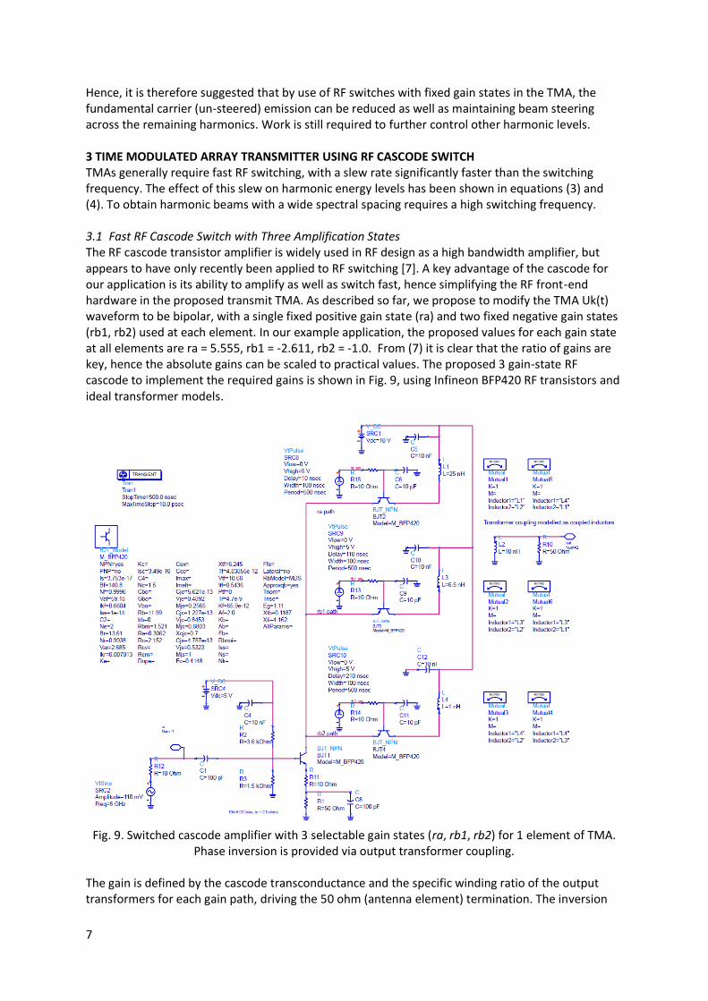
3.1 Fast RF Cascode Switch with Three Amplification States
The RF cascode transistor amplifier is widely used in RF design as a high bandwidth amplifier, but
appears to have only recently been applied to RF switching [7]. A key advantage of the cascode for
our application is its ability to amplify as well as switch fast, hence simplifying the RF front-end
hardware in the proposed transmit TMA. As described so far, we propose to modify the TMA Uk(t)
waveform to be bipolar, with a single fixed positive gain state (ra) and two fixed negative gain states
(rb1, rb2) used at each element. In our example application, the proposed values for each gain state
at all elements are ra = 5.555, rb1 = -2.611, rb2 = -1.0. From (7) it is clear that the ratio of gains are
key, hence the absolute gains can be scaled to practical values. The proposed 3 gain-state RF
cascode to implement the required gains is shown in Fig. 9, using Infineon BFP420 RF transistors and
ideal transformer models.
Fig. 9. Switched cascode amplifier with 3 selectable gain states (ra, rb1, rb2) for 1 element of TMA.
Phase inversion is provided via output transformer coupling.
The gain is defined by the cascode transconductance and the specific winding ratio of the output
transformers for each gain path, driving the 50 ohm (antenna element) termination. The inversion

8
for rb1 and rb2 is provided by the winding phase of the (ideal) transformers. Keysight ADS
simulations of both the gain and switch change-over delay (indicative of ramping slew) are shown in
Fig. 10 - Fig. 13 as time-domain plots for operation at a 5GHz carrier. The ra output power obtained
is 4.4dBm.
Fig. 10. ra turn on delay.
Fig. 11. ra to rb1 transition, note required gain change and phase inversion is obtained after
changing from ra to rb1.

9
Fig. 12. rb1 to rb2 transition, note required gain change obtained (phase also remains inverted).
Fig. 13. rb2 turn off delay.
From Fig. 10 and Fig. 13, it is clear that the element turn-on and turn-off times are less than 2ns
(though some further amplitude ramping is seen at turn-on, due to the transistors re-biasing). In this
ヮ;ヮWヴげゲ ヮヴラヮラゲed TMA bipolar gain application the cascode is never in an all-off state, hence these
delays will not be experienced during normal operation.
From Fig. 11 and Fig. 12 the delay when switching between operational gains (ra, rb1, rb2) can be
seen to be less than 1ns, representing the normal operation in the proposed TMA. The required
phase inversion between output from ra and rb1 or rb2 is also apparent. These results demonstrate
both the switching speed benefit of the cascode, when used as a low-cost switch for TMAs, and also
its suitability for element bipolar gain control.
4 Conclusion & Next Steps
There is currently much interest in beam steering for future 5G mobile systems. To be commercially
viable, such systems must be cost-effective and power-efficient. The TMA techniques described in

10
this paper may be applicable to handset mmWave antenna arrays constrained to point traffic to only
a single base station at any given instant.
If required, a single harmonic beam could be selected, from all generated, by appropriate use of
both a high switching frequency and frequency-agile RF carrier oscillator (modulated with user data)
driving the array with frequency selective filters placed before each antenna element (or with
suitably narrow-band elements) to select the desired harmonic. However, this technique would
waste the energy on the unwanted harmonic beams. An alternative and elegant solution could use
the harmonic optimisation approach in [8], where the structure of the switching waveform is
constructed of sub-pulses that are optimised to increase energy for a desired harmonic whilst
suppressing unwanted harmonics.
Although this paper has focused on a transmitter TMA, the concept of the 3 gain state cascode
switch could also be applied for receiving arrays, using cascode LNAs, or indeed in a transceiver
array.
The cascode amplifiers require use of phase inversion; for convenience modeled in this paper as an
(impractical) ideal transformer and subsequent combining and feeding into a radiating element. We
anticipate conducting further research around these phasing, combining and antenna functions to
form a single radiating structure -taking feeds directly from an elementげゲ cascodes.
Alternatively, rather than trying to suppress the harmonic beams, they could be fully employed in a
simple bistatic radar system as discussed, which is a particular focus of our future work.
Thus, we intend to further explore the TMA in both communications and radar applications, via
demonstrator PCB systems designed at X-band.
References
[1] S. Kutty and D. Sen, "Beamforming for Millimeter Wave Communications: An Inclusive Survey,"
IEEE Communications Surveys & Tutorials, vol. 18, p. 25, second quarter 2016 2016.
[2] W. H. Kummer, A. T. Villeneuve, T. S. Fong, and F. G. Terrio, "Ultra-Low Sidelobes from Time-
Modulated Arrays," IEEE Transactions on Antennas and Propagation, pp. 633-639, 1963.
[3] Y. Tong and A. Tennant, "Simultaneous Control of Sidelobe Level and Harmonic Beam Steering in
Time-Modulated Linear Arrays," Electronics Letters, vol. 46, p. 200, 2010.
[4] Y. Tong and A. Tennant, "A Two-Channel Time Modulated Linear Array With Adaptive
Beamforming," IEEE Transactions on Antennas and Propagation, vol. 60, pp. 141-147, 2012.
[5] G. Li, S. Yang, Y. Chen, and Z. Nie, "A Novel Beam Scanning Technique in Time Modulated Linear
Arrays," Antennas and Propagation Society International Symposium, 2009. APSURSI '09. IEEE, 2009.
[6] E. T. Bekele, L. Poli, P. Rocca, M. D'Urso, and A. Massa, "Pulse-Shapping Strategy for Time
Modulated Arrays - Analysis and Design," IEEE Transactions on Antennas and Propagation, vol. 61, p.
13, 7 July 2013 2013.
[7] M.-K. Cho, I. Song, J.-G. Kim, and J. Cressler, D., "An Active Bi-Directional SiGe DPDT Switch With
Multi-Octave Bandwidth," IEEE Microwave and Wireless Components Letters, vol. 26, pp. 279-281,
2016.
[8] L. Poli, P. Rocca, F. Viani, and A. Massa, "Advanced Harmonic Radiations Design in Time-
Modulated Antenna Arrays," presented at the 2015 IEEE International Symposium on Antennas and
Propagation & USNC/URSI National Radio Science Meeting, Vancouver, Canada, 2015.