tooling data collection system - regis university
TRANSCRIPT
Regis UniversityePublications at Regis University
All Regis University Theses
Spring 2006
Tooling Data Collection SystemJudith S. BrownRegis University
Follow this and additional works at: https://epublications.regis.edu/theses
Part of the Computer Sciences Commons
This Thesis - Open Access is brought to you for free and open access by ePublications at Regis University. It has been accepted for inclusion in All RegisUniversity Theses by an authorized administrator of ePublications at Regis University. For more information, please contact [email protected].
Recommended CitationBrown, Judith S., "Tooling Data Collection System" (2006). All Regis University Theses. 143.https://epublications.regis.edu/theses/143

Regis University School for Professional Studies Graduate Programs
Final Project/Thesis
Disclaimer
Use of the materials available in the Regis University Thesis Collection (“Collection”) is limited and restricted to those users who agree to comply with the following terms of use. Regis University reserves the right to deny access to the Collection to any person who violates these terms of use or who seeks to or does alter, avoid or supersede the functional conditions, restrictions and limitations of the Collection. The site may be used only for lawful purposes. The user is solely responsible for knowing and adhering to any and all applicable laws, rules, and regulations relating or pertaining to use of the Collection. All content in this Collection is owned by and subject to the exclusive control of Regis University and the authors of the materials. It is available only for research purposes and may not be used in violation of copyright laws or for unlawful purposes. The materials may not be downloaded in whole or in part without permission of the copyright holder or as otherwise authorized in the “fair use” standards of the U.S. copyright laws and regulations.

1
Tooling Data Collection System Professional Project
By
Judith S. Brown [email protected]
A Project Report submitted in partial fulfillment of the requirements for the degree of Master of Science in Software and Information Systems
School for Professional Studies Regis University Denver, Colorado
Date March, 2006

5
Project Tracking and Change History
4/24/2006 Submitted MSC698 thesis chapters revised 4/24/2006 Submitted MSC698 power point presentation 4/19/2006 Corrections recommended by Prof Archer 4/19/2006 Corrections for Appendix A margins 3/4/2006 Professional Project Schedule (Excel Spreadsheet) 3/27/2006 Partial Thesis Rough Draft 3/31/2006 Chapter 2 Review of Literature & Research 4/1/2006 Glossary 4/2/2006 Chapter 5 Lessons Learned 4/3/2006 Chapter 3 Methodology 4/3/2006 Chapter 4 Findings & Analysis 4/3/2006 Chapter 5 Lessons Learned revised 4/7/2006 Chapter 1 Introduction & Executive Summary 3/27/2006 Appendix A Tooling Data Collection Forms 3/27/2006 Appendix B Tooling Data Collection Application Charts 4/1/2006 Figure 2 Tooling Data Collection Reports 4/1/2006 Figure 3 Tooling Data Collection Relationship Diagram 4/8/2006 Work Cited 4/8/2006 Annotated Bibliography 4/8/2006 Thesis submission
6
Abstract
An Abstract of a Project Report Submitted to Regis University School for Professional Studies in Partial Fulfillment of the Requirements for the Degree of Master of Science in
Software and Information Systems
Tooling Data Collections System Professional Project
By
Judith S. Brown
Date March, 2006
This paper provides supporting documentation for the development and implementation of a Tooling Data Collection System. The project replaced a primitive Microsoft Excel log sheet. The original workstation for the data acquisition was a standalone system with limited access to the corporate network information and engineering resources. The need for a system revision and upgrade escalated due to the increasing prices of raw materials for component stamping. Refining this process to minimize the scrap generated was the main objective of the Tooling Data Collection System. The intent was for the information to provide the engineers with a mechanism to reduce the scrap for raw material, chrome vanadium stainless steel (grade 304) in particular. The project objective was to devise a method to monitor the stamping activity for the component parts: blades, bolsters, center, catchbit, miscellaneous, scale, shield, spring, and tumbler. The project clearly demonstrates the need to adhere to a project management format. Using the rules and guidelines as presented in the PMBOK 3rd edition, for project development, implementation, and execution definitely would have enhanced the deployment process of this system.

7
Acknowledgements
I extend sincere gratitude to all who have encouraged and supported my efforts throughout my career, in the field of information technology, which has spanned over two decades. The development and deployment of this Tooling Data Collection System significantly contributed to my decision to pursue the Master of Science in Computer Information Technology with Regis University. My quest was to acquire knowledge and learn the available tools and appropriate techniques for software requirements and processes necessary for successful project management and execution. I would like to also express appreciation to Delora Bradish (outsource contractor) for her expertise in Microsoft Access and Microsoft SQL and contributions to the development of the Tooling Data Collection System. Additional acknowledgement to W.R. Case & Sons Cutlery for the use of portions the tooling data collection system. My role was project lead developer under the direction of Jay Bradish (IT Director) at Case from fall 2003 � summer 2004.
A special thanks and appreciation
For those who believed in me,
Especially when I hesitated to believe in myself.
8
Tooling Data Collection System Professional Paper
Table of Contents Tooling Data Collection System......................................................................................1
Project Tracking and Change History ..................................................................5 Abstract..................................................................................................................6 Acknowledgements ................................................................................................7 Chapter One � Introduction..................................................................................9 Chapter Two � History of the Project.................................................................20
W.R. Case & Sons Cutlery Shop Floor Diagram ................................................29 Chapter 3 Methodology .......................................................................................33 Chapter Four � Findings and Analysis ...............................................................42 Chapter Five � Lessons Learned and Next Evolution of the Project .................48 List of Diagrams ..................................................................................................55
Tooling Work Flow Diagram.............................................................................55 Tool and Die Report Button VBA Code Diagram ..............................................56
List of Figures ......................................................................................................57 Figure 1: UML Entity Relationship Diagram pg. 58.....................................57 Figure 2: Tooling Data Collection Reports pg. 1-6.......................................57
Bibliography ........................................................................................................60 Glossary ...............................................................................................................62
Appendix A: Tooling Data Collection System Forms.........................................65
Authorizations
Certification of Authorship of Professional Project Work pp. 2 Advisor Professional Project/Faculty Approval Form pp. 3 Authorization to Publish Student Work pp. 4
Figure 2/Appendix B AddOn
Figure 2: Tooling Data Collection Reports pp. 1-6 Appendix B. Tooling Data Collection Application Charts pp. 1-8

9
Chapter One � Introduction
W.R. Case & Sons Cutlery, a Zippo Manufacturing Company, is a knife
manufacturer located in northwestern Pennsylvania. The company�s origin may be traced
back to the �turn of the century, during a time when pocketknives were as essential as a
watch.� (W.R. Case, Tales and Traditions, n.d.)
It is with pride that Case announces their products are �Made in America�. In
2003, the Case Knife Collector Club consisted of approximately 16,000 members of
which 99% resided in the United States. This club has added 2,000 additional members
over the last 2 years. Their reputation and the fact that the products are produced
domestically are two main strengths that give Case a competitive edge in the industry.
Case manufactures pocket knifes of many varieties. In addition, they manufacture
limited editions of knives that are most attractive to the collector audience. Case knife
blades have a distinctive stamp. The origin of the stamping identification mark, in itself,
is distinct and evolved from their manufacturing process (es).
�The Famous Case XX Trademark. The history of the trademark goes back to the
early days of W.R. Case & Sons Cutlery Co., when the ?XX? was used as a quality
check system during the process of heat-treating. When the blades were put through
the initial hardening furnace, and ?X? was marked on the pan holding the blades.
When the blades were returned to the oven for tempering, a second ?X? was added.
?XX? then showed that each blade had been properly and fully treated.� (W.R.Case,
Blades and Steel, n.d.)
The preservation of the distinct markings for the Case knives has become significantly
important. This uniqueness is used to retain their market niche. Another Case blade
10
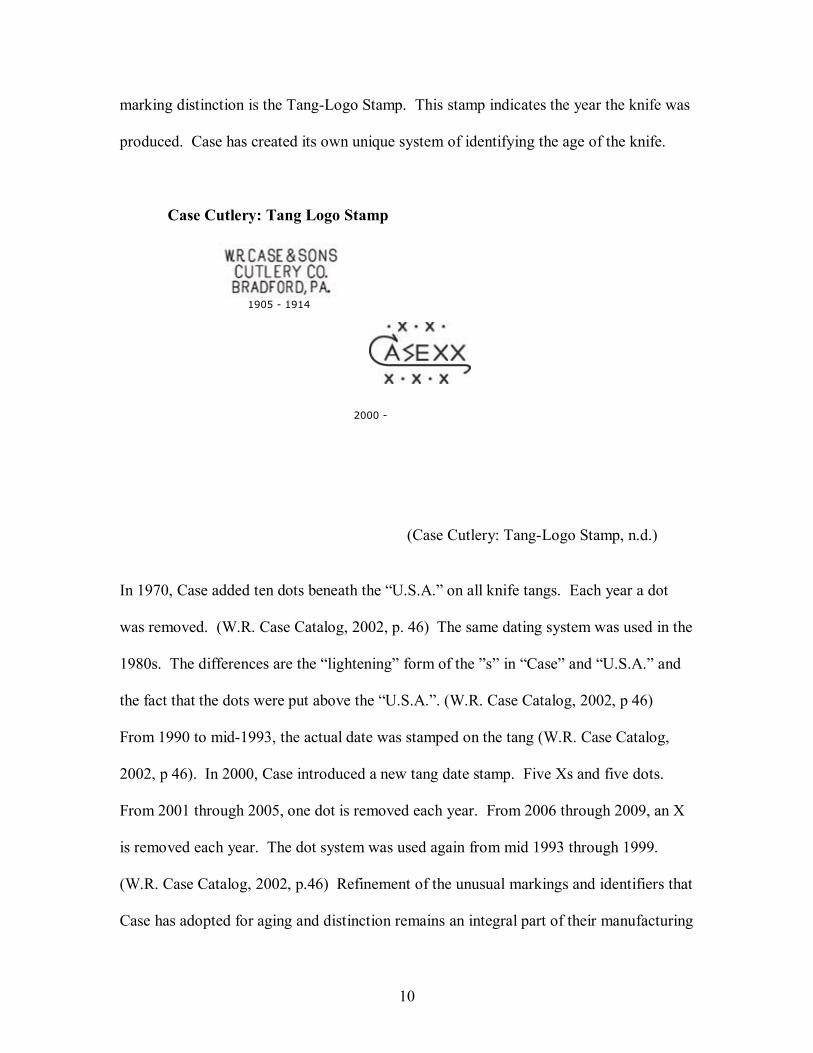
marking distinction is the Tang-Logo Stamp. This stamp indicates the year the knife was
produced. Case has created its own unique system of identifying the age of the knife.
Case Cutlery: Tang Logo Stamp
1905 - 1914
2000 -
(Case Cutlery: Tang-Logo Stamp, n.d.)
In 1970, Case added ten dots beneath the �U.S.A.� on all knife tangs. Each year a dot
was removed. (W.R. Case Catalog, 2002, p. 46) The same dating system was used in the
1980s. The differences are the �lightening� form of the �s� in �Case� and �U.S.A.� and
the fact that the dots were put above the �U.S.A.�. (W.R. Case Catalog, 2002, p 46)
From 1990 to mid-1993, the actual date was stamped on the tang (W.R. Case Catalog,
2002, p 46). In 2000, Case introduced a new tang date stamp. Five Xs and five dots.
From 2001 through 2005, one dot is removed each year. From 2006 through 2009, an X
is removed each year. The dot system was used again from mid 1993 through 1999.
(W.R. Case Catalog, 2002, p.46) Refinement of the unusual markings and identifiers that
Case has adopted for aging and distinction remains an integral part of their manufacturing

11
process. A compromise to this mark of distinction would jeopardize their reputation in
the knife manufacturing and collector industry.
The knife marking feature that prompted the tooling data collection system
project is the �SS� or �CV� which identifies the raw material composition of the knife
blade. There are a number of ways to tell if your knife is stainless steel or chrome
vanadium. The stamp on the blade tang identifies the steel. For example if the stamp says
�USA 6207 SS�, SS indicates that the knife is made of stainless steel. The chrome
vanadium steel will be indicated in the same place with a �CV� instead of an �SS�. The
knife box or packaging has an item number on the UPC label that includes the �SS� or
�CV� abbreviations. Most stainless steel knives come in a dark green Case knife box,
while the chrome vanadium knives are packaged in a white box. (W.R.Case, How can I
tell, n.d.) The grade of the markings is classified as a quality assurance issue and is not in
the scope of this project. The process for assurance of a clean, distinct stamp and cut
process was within the engineering specifications. The scrap rate directly affected by the
pattern stamping process was the area of most concern.
In order to retain a competitive edge in the industry and maximize the corporate
profit margins, steps and procedures needed to be taken to minimize the scrap rate that
appeared to be increasing for the stamping operation involving chrome vanadium
stainless steel (food grade 304). This project occurred from 2003-2004. According to the
2004 Nickel & Stainless Market Analysis publication, �stainless steel scrap prices and
chrome steel scrap on the increase�. (Nijkerk, 2004) Capturing the processes that were
causing the highest rate of scrap was the objective of the tooling data collection system.
Distinction needed to be made as to which process was the leading scrap contributor.

12
Narrowing down which step and how many others needed to be altered of the 160 knife
process steps (W.R. Case, Anatomy of a knife) would be a challenge.
The original proposal was to modify the current data collection procedure that
was in place. This consisted of a spreadsheet, paper templates, notepads, etc. Initial
investigations revealed that the current system was totally inconsistent and lacking in
precision. The current computer interaction was a standalone workstation with limited
network capability and authorizations. All workstation functions were logged with a
single system sign on. Essentially, there was no method of security. All update and
access capabilities existed on a single workstation located directly in the manufacturing
area. There was faulty physical protection of the data. It made minimal use of the
company network environment resources for storage, security, and backup. Availability
to a broader range of users at various levels in the manufacturing work flow process was
virtually non-existent. At times, version control for the logging file was questionable and
required investigation to establish the correct version.
After careful evaluation and consideration, it was decided that using the previous
information and remapping it to a newly created system would be too difficult of a task.
Even the column headings and data formats were inconsistent among the worksheets that
contained information for the same stamped component. The various blade component
possibilities for tracking include:
California clip blade Pocket clip blade Pen blade Razor blade Saber blade Sheepfoot blade Spear blade Spey blade Wharncliffe blade
13
The spelling variations in the old tracking and logging system for �spey blade� alone
included: spay, sp, bld, spey, and blade. The discrepancies and variations were evident
for all nine of the component types. Blades, bolsters, catchbits, springs, scales,
miscellaneous, tumblers and shields needed to be tracked in a format that was consistent
with a system that could accommodate the field requirements for each component. The
previous system with inadequate retention of past information would not serve any
purpose for the present or future manufacturing process (es). There was a method in
place for logging an incident on paper for tool failures and breakdowns. Sporadic
changes were logged when the components were scrapped because an entire stamping
press run produced faulty output. This paperwork was stored in a file cabinet
periodically referred to for date or event verification. On occasion, the paperwork was
referenced for operator participation so the engineers could seek them out for further
investigation of a problem. The action for resolution was not stored with any of the
paperwork containing the initial problem or trend. Whether or not any logging was
necessary was left up to the discretion of the tool and die maker or the press operator.
Periodically, the engineering department would request logging activity to evaluate the
performance of a component for use in a future product. In any event, the method of
which the data was accumulated was not conducive for formulating decisions or
conclusive enough to accommodate recommendations for altering workflow procedures
or manufacturing process (es).
In addition, the old system used Microsoft Excel 97 software application that
would need to be upgraded to a newer version of Microsoft for continued vendor support.
14
There was no documentation for the previous system. The only method of training on the
old system was word-of-mouth, relying primarily on associates who had been with Case
from 10 � 30 years. It was obvious that there would not be much of the old system that
could be salvaged. The entire system would need to be discarded. However, the
theoretical concept of the old system would serve as a foundation of the new system for
the relationship between the process (es), component parts, and pattern/tool classification.
Supporting evidence for necessitating a tooling data collection system was
prevalent in all related manufacturing areas. Engineering had high expectations and was
eager for any data they were able to gather. Cooperation was evident in all areas of the
plant that were affected by the stamping process. Basically, the audience was prepared
and eager to participate in any action plans initiated for a tooling data collection system
to be developed in-house. The ERP system was inadequate for the function of tool
tracking and production data collection. A system that would integrate and bridge the
ERP and production shop-floor was mandatory to achieve the objective of tooling data
collection. Informal discussions and interviewing for the project began. Gathering
information for the specifications and requirements step needed for a tooling data
collection system was initiated and project participants were elicited. Input was solicited
from the tool and die workers, press operators, supervisors, engineers, and managers. The
opening of the communication channels generated a vast array of questions.
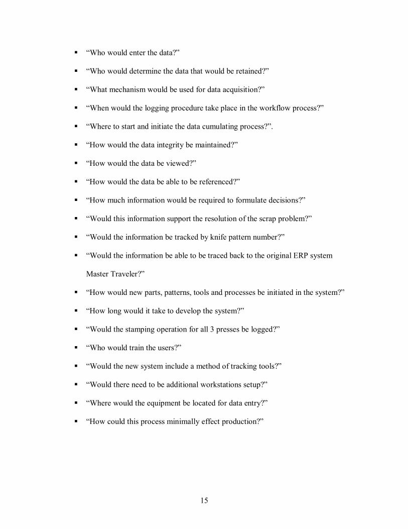
Questions that became evident:
! �Who would steer the project?�
15
! �Who would enter the data?�
! �Who would determine the data that would be retained?�
! �What mechanism would be used for data acquisition?�
! �When would the logging procedure take place in the workflow process?�
! �Where to start and initiate the data cumulating process?�.
! �How would the data integrity be maintained?�
! �How would the data be viewed?�
! �How would the data be able to be referenced?�
! �How much information would be required to formulate decisions?�
! �Would this information support the resolution of the scrap problem?�
! �Would the information be tracked by knife pattern number?�
! �Would the information be able to be traced back to the original ERP system
Master Traveler?�
! �How would new parts, patterns, tools and processes be initiated in the system?�
! �How long would it take to develop the system?�
! �Would the stamping operation for all 3 presses be logged?�
! �Who would train the users?�
! �Would the new system include a method of tracking tools?�
! �Would there need to be additional workstations setup?�
! �Where would the equipment be located for data entry?�
! �How could this process minimally effect production?�

16
! �Why the information accumulated would prove valuable for prompting
modification of engineering process(es) to improve the quality and quantity of
the stamping operations for chrome vanadium stainless steel�
! Lastly, �what would happen to the workers who were illiterate?�
There was an immense amount of questions, information and knowledge that needed to
be captured and organized. A methodical approach for gathering, classifying, and
ranking the information for the tooling data collection system was required. Determining
the scope of the project and the objective of the project were questions that were
challenged throughout the duration of the entire system evolution.
An area that presented issues throughout the project was the role of the IT
manager and acceptance of a project lead within the department. As a project lead, I was
held accountable and responsible, but did not have the authority to handle any decisions
that involved the input and support from upper management. Any decisions that needed
to be made in regard to the shop floor activities were considered part of the role of the
project lead. As a result, there were times that conflicts of interest surfaced. Having to
contend with the uncertainness of how each particular issue would be approached was
trying. This also affected the engineer who was a co-leader with the project. As the
deadlines approached for phase implementations, this grey area of concern escalated to
proportions that interfered in the flow of the project deployment. Periodically, the IT
manager would reassess and focus would be shifted to an entirely different project. This
had a distinct bearing on the delivery of the tooling data collection system. Shifting the
17
focus and reassembling after being derailed to another system would have been easier
had the proper tools for project management been applied to this system. If applied, the
recommended rules and guidelines presented in the Project Management Body of
Knowledge (PMBOK) would have definitely had a positive effect on this area of the
project. Changes to the deadlines due to reallocation of manpower resources would have
been reflected in the supporting project documentation. Discrepancies that evolved from
working on simultaneous projects would have also been documented and recognized
through a formal procedure. The method that was used of changing direction, timelines
and system objectives was not remembered when the time came to justify the system
status. The fact that the system was not on target for deadline completion was partially
accurate. If the changes were taken into account, then is would have been within range of
the anticipated project schedule.
Basically, the tooling data collection system was a success. To the best of my
knowledge, the system is �in use� today. The system was designed for other operations
to be captured with small program changes. The pull program for the ERP system Master
Traveler contributions would need to be altered if the engineers wanted to monitor the
stamping results for another type of stamping component or another type of raw material.
The effort required would be minimal and the information would fold into the system as
it was written to accommodate. The cross-training of knowledge that naturally occurred
due to the open communication channels would allow for future enhancements without
the learning curve that was required for the tooling data collection system. The cost and

18
time for man power for future enhancements would be significantly less with the
knowledge and education that all had acquired in the original project.
The tooling data collection system was to determine the origin of the chrome
vanadium stainless steel scrap rate increase. The exact percentage of the scrap level
decrease, for which the tooling data collection system was accountable, remains
unknown. The fact that Case continues to produce quality knives using chrome
vanadium is proof that the process requiring investigation and evaluation, was worth
continuing. As The Knife Shop advertises, �you can�t hone a good blade out of bad steel.
That�s why Case uses only premium quality steels, ordered and tested to fit our
demanding specifications. These include: Chrome vanadium-a special formula of alloyed
cutlery steel known for its ease of resharpening. A quick touch-up will bring back a
chrome vanadium blade�s original sharp edge. (Tip: Extra care is needed with chrome
vanadium. Keep a thin film of oil on the blade to maintain the finish of the steel.) (The
Knife Shop, n.d.) 1
The inventory and health system for all tools evolved essentially by accident, on
behalf of the tooling data collection system will prove valuable for Case for engineering
changes for the past, present and future of products designed. One outcome of the
tooling data collection system is the immense amount of accurate information that is now
available in a format that is conducive for formulating judgments and decision-making.
The information is accessible to the appropriate people. The system is maintained and
1 The Knife Shop: Re-printed from: W.R. Case & Sons Cutlery Company THE CASE EDGE

19
updated by authorized personnel. The IT department supports the required resources to
maintain the integrity of the system information. The system �empowered� the Case
Associates who were involved and continue to be involved with the system input, outputs
and outcome.
20
Chapter Two � History of the Project
In order to determine the specifications and requirements for a tooling data
collection system, all resources such as the materials, software applications, hardware,
and equipment available needed to be evaluated. The following is a brief description of
the information support and services potential of Case Cutlery prior to the tooling data
collection system implementation.
The Information Technology for Case Cutlery consists of a Mapics (Pointman)
ERP system, EDI Gentran supplier/customer system, and predominately Microsoft Office
integration applications. The ERP system uses Oracle databases. The Oracle release that
is in production at Case is determined by the level of which the ERP system is operating.
Case in-house application development and deployment tools are: Microsoft Access,
Crystal Reporting, and Microsoft Exchange Server for Email and Microsoft Front page
for the corporate Intranet. Use of Microsoft SQL was encouraged for future application
database development. All in-house developed systems may extract data from the Oracle
databases. The data is only permitted to be updated or altered though the methods which
qualify under the maintenance contractual agreement between W.R. Case & Sons Cutlery
and Mapics, Inc. The ERP system is �pure� in the sense of the application code and
theoretical functionality.
In-house application development historically created systems that were
extractions from the ERP system. Attempts to decipher the criteria for extractions that
would contain accurate and expected results required many programming man-hours.
21
When a reliable process generated the desired information, it was retained as a template
and used for continuous extractions. The Oracle ERP/APS was written and supported by
Mapics permitting only information pulls. The database maintenance utilities were
executed on an �as needed� basis. The extents for �primary� files were checked on a
daily basis and compared to the previous days� information. Oracle file maintenance
would be scheduled for the first available weekend after it was determined that the
maintenance was required. The utilities updated the file indexes and were individually
requested to run. There were minimal mass batch procedures. Although, this would
appear to be cumbersome, the system was small enough to manage with this method.
The interaction of the ERP system with another system, such as the tooling data
collection, would potentially demand that the ERP maintenance be formalized. The
integration with other system would force the ERP maintenance process to outgrow the
capacity for which the procedures were currently being executed.
As a programmer/analyst, my work encompassed massive changes and improving
the Case Intranet presentation, the Case Collector Club data gathering and statistics
systems, and creation of the tooling data collection system for tracking all blanking
operations using stainless steel material for the tool and die prep and the press area. This
Engineering system proves valuable when identifying primary areas of concern in a
proactive manner. It prevents scheduling a part for production when the tool is down due
to breakage and introduces the ability to maximize tool and die and press component
maintenance.

22
The basic theories of Case in-house development was passed by training �as
needed� among the IT department. With less than a handful of people, this department
had only one person dedicated to development. Cross-training was necessitated for
covering vacation and employee rollover/replacement. Over ½ of the IT department had
20 � 30 years of service in IT at Case. Their vision was narrow with very little exposure
to outside influences for technology methods. However, it was clearly evident that the IT
developers were extremely versed in the methods, functions and tools practiced at Case.
Departmental meetings were conducted, for the most part, on a weekly basis. Someone
in the meeting generally volunteered to take notes and provide a brief summary of the
meeting agenda. As a result of this type of process, all departmental meeting attendees
were aware of the projects of which each other was involved. Deadlines were discussed
and objectives and issues were communicated. Actual engagement of open discussions
was limited in the �team meetings�. Each team associate informed the group of their
immediate concerns and efforts at the surface level. An in-depth analysis of any event,
process or procedure would occur on a one-to-one basis at a later time. Isolated
discussions and issues would evolve informally without any notes or follow-up
communications. Effective email interactions was not encouraged nor practiced. Based
on the departmental meeting approach that was currently accepted, the potential was
limited for projects that involved a cross-group and interdepartmental interactions. This
non-interactive environment would suppress the initial momentum of the novel
�integrated� tooling data collection system.
23
The background for departmental integrated systems was virtually non-existent.
IT support function was mainly to create reports from the ERP system that were not
provided by Mapics. Filling the gaps of what was missing from the purchased product.
At times, IT was assigned to remove the previous �band-aids� when the new Mapics
release would incorporate these concerns as enhancements to their systems. Purchase
Price Variance system, Scrap system, and Case Collector Club system are a few
examples of these types of systems. Those that were created in-house were developed in
Microsoft Access �97� database systems as late as 2003. Since Microsoft support would
be removed for �97�, one project for Case IT was migrating Microsoft Access systems to
a newer version. The decision was to approach this migration in small increments when
confronted with a problem within the system. The determination would be made to
adjust the database to at least, Microsoft Access 2002. Otherwise, any new systems
would be mandated for development in the newer Microsoft Access version.
An outside contractor was retained for the sales and forecast Microsoft SQL
database systems. Periodically, the outside contractor would assist with small functional
implementations. These projects were generally performed over a days� work on an �as
needed� basis. This did not involve critical nor time-consuming process assistance. The
outside contactor would be solicited for specific areas of concern with the Tooling Data
Collection System. Prior to this Tooling Data Collection System, the outside contractor
would totally develop a system that would basically be �click-and-drag� in-house
implemented to production. A user-guide would be provided for training and referral.
The services for outside intervention were minimal up to this point in time. For the
24
Tooling Data Collection System, the particular request for outside contractor services and
intervention were:
• Microsoft SQL DTS (Data Transformation Script) development required
for the ERP integration and extraction validation procedures.
• Microsoft Access front-end GUI form movement capabilities of
segregation regarding data security measures and limitations
This was a critical system application. It involved functions requiring a greater
degree of interaction and communication. Essentially, this contribution was a key
component in the success of the Tooling Data Collection System project. The outside
contractor had limited exposure to the manufacturing process, procedures, terminology,
and technical demands. The major challenge would be to project this information in a
method that would facilitate the exchange for each developer to expedite their process
functions. Basically, the objective between me as the lead developer and the outside
contractor would be to utilize each others talents and skills in a complimentary fashion. I
would share all of my 16 year skills (predominately IBM software base) of developing in
a manufacturing environment, knowledge of the terminology, and processing procedures.
The outside contractor would provide a link of expertise with the Microsoft platform
products and technical navigation technique for GUI interventions. This exchange would
be critical to remain on target with the project deadlines and for avoidance of anticipated
project pitfalls. 2
2 For the purpose of this thesis, the Microsoft SQL portion of the system was converted to Microsoft Access. In
addition, the technical Data Transformation Services cross-over procedure is not in the scope of this paper.
25
The Case environment is best described as islands of information silos segregated
by department. These barriers were positives when attempting to obtain information that
related to the specifics of the department functionality. All information pertaining to the
department was available in that particular area. There were very few situations where
the information overlapped. The negatives from the information silo barriers outweighed
the positives. The ERP system contained the information necessary for the workflow of
the manufacturing process area. The ERP system flow provided guidelines that steered
the necessary actions or in-action required for altering workflow process (es). The
technical and analytical information needed to provide the mechanisms for corporate
decision-making requirements outside the scope of the ERP system was limited. Action
team committees had been formed in order to address specific problems and concerns.
These teams consisted of representatives from the middle-management corporate level.
They operated as liaisons between upper-management and the shop-floor workers for
communicating specified reporting requirements. The action-committees also dissolved
after the incident for which they were created was addressed. There was an outstanding
open issue that was directly related to alternative acquisition of stainless steel raw
materials. This committee was formed as a reaction to the rising scrap incidents in
production services. Past approaches to resolution of this issue were pending
implementation and also did not address the problem of �why the incident of scrap was
increasing�. The Case engineers were being held accountable for the stainless steel raw
material scrap factor. The strongest consideration that scrap incidence was on the rise
was due to the specifications; lack of adhering to the specifications, and ignoring the
communication efforts to project specifications changes. This pointed the direction for
26
improvement and investigation to the �human error� side of the equation. Since
minimal information was captured in any type of organized method outside of the ERP
system there was little data available for the engineers to research. Attempts to formulate
judgments, hypothesis and alternatives proved futile to forcing significant reductions in
the scrap factor. The engineers had devised a �wish-list� with notes and specifications
drawn on paper stored in file cabinet drawers. The �hidden� requests were backlogged
and of low-priority for allocating time or resources. It was these records and notations
that the engineers were referencing to determine if there was an action that could provide
immediate relief and lower or at least give the illusion of some semblance of control of
the stainless steel scrap rate. It was definitely time to initiate a system devised to
eliminate some of the obvious �human-error� factors that were contributing to this
problem. Simple steps such as a part ordered for production that was so new that all the
paperwork was behind the production request. They were attempting to use an area
designed for comments on the ERP system to input a tool number for a part if one had
been assigned. The comments were an inconsistent format and the tool number was often
entered wherever it would fit on the GUI. At times, this tool number was in the front of
all the text and other times, it was contained in the end of the text. There was not a
method of validation, so some tool numbers had �O� alphabetic characters when indeed
they were intended to be �0�. This posed a problem for any type of electronic processing
or extraction of this information from the ERP system.
Another obstacle that proved to be a benefit was that the Engineering and Shop
Floor users that would be steering this Tooling Data Collection System had essentially no
27
association with the IT department. They did not have any preconceived opinions
formulated from past experiences that would influence their involvement. The corporate
Information Technology capabilities, skills, expertise, software applications, and support
and services were entrenched in an isolated environment. They were physically located
in a closed area in the middle of the shop floor, as illustrated in the Shop Floor Diagram
on page 28. The IT Manager firmly controlled the interactions and interfaces for all IT
persons outside the department. Each department or area within the organization devised
their own rules for executing the goods and services that they were required to deliver.
Yet, the organizational philosophy was team-driven, �empowerment� techniques, terming
associates as co-workers and prided themselves on the implementation and practice of
newer manufacturing processes and support services. n spite of the dual philosophical
guidelines for the organizational functions, the approaches complimented one another.
The existence of the atmosphere would be challenged with colliding and conflicting
approaches questioned throughout the development and implementation of the Tooling
Data Collection System.
The �team� or mod designations within the shop floor, coupled with the Six-
Sigma quality assurance techniques were a solid foundation for the Mapics ERP System
to be incorporated. Integration of applications outside the parameters of this workflow
was territory that had not been tried. The tool number assignment system that was
previously discussed, in this section, was a reflection of this type of attempt. A brief
glimpse of the logistics of the Case manufacturing environment offers some explanation
of these qualifying information restrictions. The channels of communication between the

28
key groups for this Tooling Data Collection System are limited. The administrative and
office areas of the plant have network access and capabilities. The manufacturing area
was not in this information loop. The tool and die area had one workstation with
minimal network capabilities. The press area had absolutely no computer access. The
press operator would have to leave his module and press, walk across the department to
the tool and die area to access the closest computer in the facility. Even though the
previous demand for this interaction was insignificant in magnitude, it presented a
security breech to the network system. They did not have a user signon and would just
piggyback on the user that was logged in at the time they needed to access the system.
The boundaries were weak for security which also led to difficulty in tracing the
information. The actual person who might have entered the data that was needed to
resolve a manufacturing issue was not known. This presented a problem in that it was a
waste of the company�s manpower. Time was monopolized by scouting history of who
entered the data when the time could have essentially be better spent analyzing the data.
29
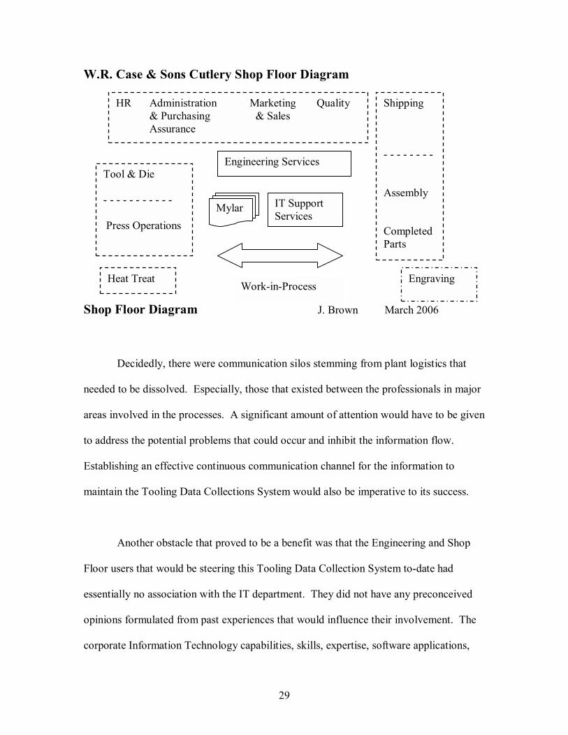
W.R. Case & Sons Cutlery Shop Floor Diagram
Shop Floor Diagram J. Brown March 2006
Decidedly, there were communication silos stemming from plant logistics that
needed to be dissolved. Especially, those that existed between the professionals in major
areas involved in the processes. A significant amount of attention would have to be given
to address the potential problems that could occur and inhibit the information flow.
Establishing an effective continuous communication channel for the information to
maintain the Tooling Data Collections System would also be imperative to its success.
Another obstacle that proved to be a benefit was that the Engineering and Shop
Floor users that would be steering this Tooling Data Collection System to-date had
essentially no association with the IT department. They did not have any preconceived
opinions formulated from past experiences that would influence their involvement. The
corporate Information Technology capabilities, skills, expertise, software applications,
IT Support Services
Engineering Services Tool & Die - - - - - - - - - - - Press Operations
Shipping - - - - - - - - Assembly Completed Parts
Work-in-Process
HR Administration Marketing Quality & Purchasing & Sales Assurance
Heat Treat Engraving
Mylar
30
and support and services were entrenched in an isolated environment. The IT services
and support were physically located in a closed area in the middle of the shop floor. The
IT Manager firmly controlled the interactions and interfaces for all IT persons outside the
department. Each department or area within the organization devised their own rules for
executing the goods and services that they were required to deliver. Yet, the
organizational philosophy was team-driven, �empowerment� techniques, terming co-
workers as associates and priding themselves on the implementation and practice of new
manufacturing processes and support services. In spite of the dual philosophical
guidelines for the organizational functions, the approaches complimented one another.
The existence of the atmosphere would be challenged with colliding and conflicting
approaches questioned throughout the implementation of the Tooling Data Collection
System. This system would forge �new� territory for the group interactions, exchanges
and working relationships. This proved to be an obstacle, yet, also an opportunity.
The following summary briefly describes the assessment of the current tooling
information system. The current tooling data collection system is a primitive excel
workbook with multiple worksheets that are not consistent with the data that is gathered.
The format is not conducive to manipulation and collection for reporting purposes.
Additional information would be needed to determine and identify the source of any
problem in the manufacturing workflow process system. The workstation contains the
only available method of modifying the information without security passwords for
accessing the data. A front-end security protection with user/password and varying levels
of capabilities within the system for user groups is needed for establishing data integrity.

31
Electronic accessibility for communication among the departments needed to be
established. Designated areas for physical data entry and computer access would need to
be determined.
Immediately, the capacity and capabilities of the Tooling Data Collections System
became a topic of concern. Looking back, this is the point at which the project scope
began to creep. The benefits of opening the channels of communication physically and
reassessing electronic accessibilities were immediately realized. Small changes, such as
read-only file accessibility on the corporate network to a broader group of users yielded
improvements in data integrity. Errors and inadequacies were addressed, care and
caution was exercised for any processes that were revised during the Tooling Data
Collection System development. It was immediately evident that the audience was fully
prepared to meet the challenge and take the necessary steps to implement a system that
would yield information that was valuable for productivity improvements. The next
procedure that evolved was the research and knowledge exchange to gain an
understanding of the manufacturing process. Acquisition of the terminology, acronyms,
tacit and in tacit knowledge would essentially be the critical driving forces for this
system. Review and comparisons of varying opinions and interpretations of the
workflow would prove to be one of the most challenging portions of the project.
Learning the contribution of each person and position required to process the
information required extensive research and observation. The difference between tool
and die production prep procedures versus tool and die maintenance prep procedures was
32
difficult to distinguish. The definition of the terminology was different depending on
where the person was in the process (es). For example, was the �part� a part in the tool
or a part to produce? Eventually, this would all be clarified once the screens for each
area were created and further definition was assigned.
As the project progressed and the scope further refined, it was clearly evident that
this tooling data collection system would be valuable for the manufacturing process.
The stamping process would be evaluated from all angles to yield a better product and
improve the quality of the components being produced. The company would have an
accurate inventory system of the tool in-house and the capability of re-using retired tools
for new patterns and products. The knowledge of the health and state of the tools would
allow production control to make better scheduling decisions. Elimination of the
manpower, time and production resources for scheduling products to be produced from
broken tools would be another system benefit. Accessibility, of the information, for the
engineers steering the production process to monitor the progress and proactively address
problems would significantly reduce the raw material scrap rate. Data reflecting the
stamping process and ranges in relation to the drawing and mylar specifications would be
able to accumulate. The engineers could evaluate trends. Corrective action steps could
be taken, such as, modifying process (es) and refining information flow bringing positive
results to the profitability of the organizations manufacturing process. Press machine
maintenance could be scheduled at periodic intervals that would coincide with the
production orders to produce better results. �Proactive� planning versus �reactive�
responses would be the new initiative.

33
Chapter 3 Methodology
The rapid application development (RAD) lifecycle with prototype sampling was
the method of deployment for the Tooling Data Collection System. Organized meetings
of all persons directly and often indirectly associated with the implementation of the
system were present. The audience that was exposed, educated and participated in the
evolution of the Tooling Data Collection System contributed immensely to the successful
outcome of the system. Although, formal sessions were held with representatives from
all groups, each group was address individually and as a whole. They understood their
position, expectations and contribution in the system execution. They also had a clear
understanding of the other players and their parts. Essentially, the project orchestrated in
parts and as a whole with integrations rehearsed and rewritten. Workflow functions and
timing were interchanged until the system worked for them and provided the desired
outcome. Appendix A exhibit shows the screen variations with similarities and
differences between the manufacturing functions.
The Incremental Model progressing into the Evolutionary Model illustrates the
software development modeling approaches that were used for the tooling data collection
system. Appendix A is a composition of the various system forms that were created and
implemented using these models. Many of the benefits of using the Incremental Model
were realized, especially the less cost and time required to make the first delivery.
(Christensen & Thayer, 2001, p188) As Christensen and Thayer suggest, the
disadvantage of managing the resulting cost, schedule, and configuration complexity may
exceed the capabilities of the organization was also prevalent with the Incremental Model

34
approach (p. 189) The opportunity to capitalize on the process of user feedback proved
advantageous. The user feedback provided from the actors and audience of the tooling
data collection system for each phase allowed the opportunity for the software to be
corrected and issues resolved. Minor issues, such as a field error that was protected or
the data format was inaccurate were corrected as they surfaced. There were three distinct
functional areas: Engineering, Press, and Tool and Die Prep. The incremental phases
were of the setup for the associations of the primary conceptual relationships: tool
(quantity of 600), part (quantity of 16,000), pattern, mylar, and drawing. Once the proper
affiliations were entered into the system, the phase of tooling activity could be initiated.
The logging efforts of production stamping were reflected in each record recorded in the
tooling data collection system. The accumulation of the system information led to the
next phase of implementation. The information was analyzed and consolidated in order
to automate the requirements for tooling maintenance and proactively reduce production
scheduling errors. The last phase of the first group of increments was to access the data
of the press operator logging and tool and die prep logging. This information represents
the initial scope and objective of the project. Based on this information, the engineers
were able to make decisions that would improve the process (es) and procedures for
production component stamping. These improvements would, in turn, reduce the scrap
rate for the chrome vanadium stainless steel.
One area of system complexity that proved challenging when involved with the
technical engineering designs was with the X and Y axis data entry. The fields could not
be initialized as zero, as zero has value when evaluating the origin of a problem. The
35
default value for the fields throughout this system is null. This is due to the X and Y
coordinates as the hole (X) and hole (Y) values reflect errors whether they are positive or
negative. The object of this system is to provide retention for the operators to log the
discrepancies between the placements of the punched parameters. Therefore, where there
are values is what will be evaluated. If there are no values, then all is within range of
what the specification from the drawings and mylars indicate according to the engineers.
The initial issue tracking was informal. A word document with the issues logged
served as the mechanism for retaining the date, description and outcome. The
management instructions were that under no circumstances would this system interfere
with production. If the user was unable to enter in the information, such as a field
attribute lockout, then they were to report the problem and continue on with the
production request. When the system rolled out, the problem surfaced of duplicate
master travelers. The ERP system that preceded the tooling data collection system in the
workflow process permitted the production controllers to change requests for production
after they had been released. This, in turn, generated a duplicate request for the same
components to fill the same sales order. As a result, there would be an excessive quantity
produced which would effect the inventory counts and overhead. The tooling data
collection system prevented the occurrences of the master traveler duplication by alerting
the operators that there was an error. Investigation in these situations eventually forced a
new method of delivery of master travelers. An additional edit routine process was
placed in the front-end of the tooling data collection system. The ERP system updates
and changes were edited against the operations for component stamping. If there were
36
any discrepancies, then it was recorded in the master traveler error table. An email was
automatically generated to the appropriately responsible parties to correct the error. Once
corrected, the engineer who was accountable for the correction was authorized to notify
the tooling data collection system with an override that would log this process.
Another issue that confronted the users were confronted with in the initial phase
of implementation was the part request without authorization. This issue was where
parts were being requested for production without a corresponding engineering drawing.
How could a part be requested from a sales order for a component part for a production
stamping process for a final knife pattern assembly without an engineering drawing?
Obviously, the checks and balance procedures that were put in place in the manufacturing
administrative process were lacking in some manner. This proved to be a procedural
problem of retired part numbers that were not accurate in the ERP system, component
parts that had once been purchased and changed to manufactured needed to have the ERP
system status changed accordingly and also the new part process for the manufacturing
facility needed to be procedurally defined.
Each of the implementation issues were addressed as the system deployment
progressed. The end result was the revision of the system and folding in to the shop floor
scheduling. More effective measures for scheduling manpower, machines and ordering
of raw material were the end-result. A main engineer managed the ERP to Tooling Data
Collection workflow. Data Transformation Scripts were created in Microsoft SQL that
would automatically generate an email blast to all departments of the error alerts. These
37
include: a part requested for production without a Mylar or Drawing association, and a
data entry error of a purchased part request for manufacture production scheduling.
Many flaws were forced to be addressed and resolved before the shop floor
scheduling routine. The workflow of the entire production system fabrication process
altered from a reactive to proactive approach. Of course, tools would break � but, the
tooling data collection system offered a form of communication for the teams to
collaborate. The downtime for tool repairs was decreased. Instead of a tool marked with
a �Red Tag� in the retrieval system. The tool was physically marked and a notation was
in the system on the tool master, then the schedule alerts could restrict production orders
from being issued for the �down� tool or machines. The communication channels opened
many avenues for information cross-referencing. Weaknesses were visible allowing
engineers to evaluation and capitalize on this information for design considerations for
new products and future production endeavors.
The exact monetary benefit of the tooling data collection system project was not
available. In order to determine the benefits of error prevention as a result of the system,
one would have to review the historical incidences of occurrences that resulted from the
system resolutions. In summary, many errors were resolved, procedures altered and
process (es) improved. The information from the system was well received. User trust in
the system and the data it provided was evident. Due to a personal change in
employment, I am not in a position to expand on the evolution of the system beyond the
initial release, nor offer any monetary compensation figures that were realized over time
38
due to the presence of the tooling data collection system. It was evident while defining
the project objective that the tooling data collection system was beneficial to the
manufacturing process. Continuous improvement by refining the manufacturing process
(es) confirms Case�s commitment to quality beginning with the materials used in
production and perfection by the talented hands of master craftsmen and skilled
employees who make the Case knives. (Cozy Camping Catalog, n.d.)
The technique for controlling the system security was through the user sign on.
The sign on associated with one of three groups: press, tool, or engineering. A SQL table
contained the user sign on and the forms that were permissible for access based on the
sign on. Reference to this grouping is in Appendix A which contains the screens and
forms with a brief description for the tooling data collection system original
implementation. Appendix B contains a list of the tables and files used for the original
implementation. The following list highlights a few of the system tables and the purpose
for which they were created. Some of the tables not mentioned, such as the views, were
created for SQL performance enhancements while others were created for retention of the
stamping data and tool health.
dbo_CategoryTable � this table was created as a control mechanism to steer the
categories and the form that reflects the information that relates to the category. (ie.
Blade, spring, scale, bolster, shield, tumbler, Center, catchbit)
39
dbo_DrawingMaster � table containing drawings that correspond to all stamped
component part numbers.
dbo_Master Traveler Table � Critical table for the system functionality. This table was
regenerated every night after the ERP system scheduler completed processing. The
objective was to determine what operations qualified for the stamping process. Those
that qualified were prepared in the Tooling System for capture, acquisition and retention
of the information relating to the stamping process (es). The data was updated with the
category based on comparisons against the master table. This category assignment
assured that the proper forms and files would be alerted
dbo_MasterTravelerError Table � this table was created to contain the logged errors
for all Master travelers that were processed through the MAPICS ERP system that
contained errors. The information did not meet the specifications for validation. Some
common examples were that the component part in the bill-of-material ERP system were
labeled as �Purchased� or �Compete� when they were truly �Component parts� and
�Manufactured� in-house. Another error is �Part Does Not Exist� which indicates that
the part is not recognized throughout the system. Directions to stamp product without
and associated tool were being passed through the system which is totally erroneous. All
errors needed to be corrected by the engineer before they could be released into the
Tooling System for production. This procedure was created as a result of the
discrepancies that surfaced once the pilot runs were in place for the Tooling System.
Massive corrections to the ERP system were initiated as a result of this process.
40
Accuracy between the information systems created a new assurance for all audiences.
Sound judgment and decision-making strategies evolved. The errors lessened and quality
improved.
dbo_ToolingSecurityMaster � This provides group security; tooling, press, engineering
and administration. The permitted forms accessibility is associated with each grouping.
dbo_ToolMaster � contains a tool number for all active and inactive parts; sometimes
are brought back out of the tool graveyard (off-site storage) and modified for reuse for a
new product that needs the component that the tool punch creates.
dbo_ToolandDiePrepActivity � created for all activity to log and retain indicators and
lengths that would display the life and health of the tool and the tool components.
dbo_PunchDieLifeTable � future release (proactive method for determining reorder
points for the Main Punch(s) to eliminate lead time restrictions.
dbo_DrawingMasterView� table containing drawings that correspond to all stamped
component part numbers used for performance improvement.
The RAD prototype software presentation method expedited the delivery process
of the system. At the time, Java applications and object-oriented theoretical approaches
were not used at Case. However, future conversion of the tooling data collection system

41
to the object-oriented practices might be justified. The potential to improve the reuse
capabilities with the java application techniques would support this theory. The
Microsoft Access and Microsoft SQL software applications support the accessibility and
delivery of the tooling data collection system in the Case manufacturing environment.
The development and integration of the tooling data collection system complimented this
environment. Even a change in the ERP system would not force the issue nor necessitate
a conversion of the tooling data collection system. The Evolution Model demonstrates
benefit to be used, not just for the initial system development, but also for future system
enhancements. Advantages to using the model as presented by Christensen and Thayer
(2001): the model can be used when the requirements cannot or will not be specified, the
user can experiment with the system to improve the requirements, and greater
user/acquirer involvement is required than in the waterfall method. (p. 190)
42
Chapter Four � Findings and Analysis
One method of training for all non-production new hires at Case Cutlery was a
day as a plant worker. The experience included participating in the entire manufacturing
process and actually taking home a knife produced from the days� event. The knife
manufacturing process takes 160 steps to complete. (What makes Case different, n.d.) In
spite of exposure to the process, there is a vast area of �skilled craftsmanship� that is only
acquired through years of effort, repetition, and training. The Tool and Die makers and
Press Operators represent two fields of �skilled craftsman� in the knife manufacturing
industry. Although many of the associates had been in their positions for decades, the
assumptions and knowledge that they retained about process and procedures needed to be
exposed and shared for the tooling data collection system to be designed to gather data
that would be capable of yielding information that would be of value. Since the scope of
the knowledge spanned across many levels of expertise and many manufacturing
processes, it was decided by a group with representatives from each area to use the RAD
method. This involved a rapid-prototype sampling of the screens that the users would use
to enter information. In addition, a sample of screens for the administrative functions of
tool, part, pattern, drawing and mylar entry and maintenance. An outsource contractor
contributed to the development process. Their role in development was to create the
scripts and VBA code necessary for specific system functions. A list of issues requiring
assistance was presented to the IT manager who engaged in the negotiations for the
outside contractor. D. Bradish was familiar with the organization from previous contract
43
projects such as the sales forecast system. This was beneficial for her contributions to the
tooling data collection system. The rest of the requirements for developing the system
were achievable using corporate resources without outside intervention.
The most effective method for gaining an understanding of this Tooling Data
Collection System would be to break the concept into three parts: tool and die prep area,
press area, and engineering management. Each area tracked and contributed different
information to the total scope of the system.
The Tool and Die Prep area concentrated on the traits and characteristics of the
physical Tool. The function of the Tool and Die makers was to �prep� the tool for
production. The tool would be used to �punch� the component part out during the press
operation manufacturing process. The terminology varies depending on the component
part for which the tool is used to create. The component parts each require accumulation
of different information. This breakdown and variation may be seen by referencing the
sample screen (s) Refer to Appendix A to view samples of the system screens and forms.
Each tool has many different parts within that function to pierce a hole, indent a nail
mark, guide the raw material, and to make a concave or convex formation. One of the
objects of the data collection system was to track the size, height, length, and diameter
measurements of the various parts of the tool. The Tool and Die maker would only log
the change such as if they sharpened a main punch 1 of a tool, then the length and
diameter would be documented. If there were no changes during the tool prep process

44
then, the log would only contain the activity requested from the Master Traveler with the
operator initials and date that the activity was processed.
The Press Operator sets the tool in the press. The first step is a pilot run to stamp
a portion of the parts and then compare them to the Master Mylar. The Mylar machine
resembles a projector. The component part is placed in a vice; the light creates a shadow
of the part that may be visually viewed on the screen projector. The operator determines
whether the press settings generated a part that will meet the Mylar specification.
Adjustments may need to be made for the press to stamp a component that meets the
required specifications. All hole positions are logged for position with the X-axis and Y-
axis with a (+) or (-) depending on the location parameters. That is a business-rule that
restricts the initializing of fields in the system. Zero is significant; therefore, the fields
are blank unless there is a change. The change is tracked. This business-rule allows the
system reports to be generated based on processing records that contain other than blank.
This feature will provide the Engineer with data that may be used to determine the
drawing revisions and tooling alterations that may be necessary to improve the quality of
the component part being produced. The accuracy of the holes and guides for the
component parts determines the assembly fitting and functionality of the finished goods.
A benefit that this system yielded was the ability of the tool and die maker to determine if
the tool parts needed to be replaced before the run. Prior to the system, the tool and die
makers and press operators could only make a �best guess� based on past experience. If
a part broke in the tool during the run, the tool would have to be flagged for repair. The
stamping process would be abruptly interrupted. All the setup time and raw material
45
allocation would remain pending. This had the potential to interrupt the flow of the entire
shop-floor. A reactive position was all that could be expected and re-scheduling and re-
aligning the entire production schedule was contingent upon the tool performance and if
it met the demands of the required run. With the introduction of the tooling data
collection System, a proactive approach gave control to the production control
schedulers. The Master Scheduler ran at night and generated the shop-floor schedule for
the next day. This output was processed against the Tooling Data Collections System
information and compared all expected tool usage for �status�. The new system offered
tool �status� control mechanisms and allowed provisions for scheduling tooling
maintenance. Measurements of the parts were logged if they changed. Provisions for
storing the non-varying high and low parameter ranges for the various components were
made in the new system. Expectations were to have the tools containing 10% life or less
to be flagged for the tool and die maker for maintenance. The tool parts that broke were
expected to be automatically ordered from a supplier if they dropped below a set re-order
quantity. Many of these features were anticipated to be available in future revisions of
the tooling data collection system. However, due to the beneficial nature, some of the
features were implemented with minimal integration with the initial deployment of the
tooling data collection system. This also reflects an area that triggered scope creep for
this project.
Once the system was deployed, the data accumulation and check-and-balance
procedure for the Engineers quickly grew to be unmanageable. The engineering data
management screens were custom developed for this specific request. The engineer was
46
able to have a pulse on the entire production run for the day. They had a snapshot of the
health of the tools at their fingertips. They could monitor the flow of production for the
tool and die and press areas from within the confines of the engineering offices. This
was not in the initial scope of the project, yet provisions were made to accommodate this
request. Another alteration was that the data entry errors in the ERP system surfaced
after the production schedule was generated. This provoked a problem in the tooling data
collection system. Provisions and edits to restrict duplicate information were made in the
tooling data collection system. The engineers wanted to resolve the discrepancies in the
ERP system and production control before the shop-floor schedule fed into the tooling
data collection system. Once again, a scope creep was authorized to accommodate this
situation of integration between the systems. Extensive validations and verification
routines were implemented to process the master traveler and component parts requested
for production. Revisions were made to assure the flow of information was accurate.
The tooling data collection system implementation forced repair of the problem
where �purchased� parts were requested for stamping. Corrections were demanded for
inaccurate category groupings, for instance, a blade part number accidentally labeled as a
spring. It prevented duplicate Master Travelers and quantity errors that had previously
filtered through the manufacturing system yielding surpluses and shortages of raw
materials and component parts. Many problem areas were discovered that took minimal
effort and resources to resolve.

47
The impact of the issues that surfaced throughout the project was that the
additives deterred the project from adhering to the tentative deadlines. The IT manager
was not receptive to the constant scope changes and project alterations. However, the
deadlines were tentative and had never been formally secured or recognized. This left a
hole in the process for the project life cycle. Throughout the tooling data collection
system deployment, there were insinuations about the project shortcomings in regard to
the surpassed deadlines. In spite of this setback, there was a steady flow and evolution of
project phase implementation. The momentum of the project coordinated well with the
flow of the phase implementations and revisions. The end result was a robust system that
required minimal maintenance, exceeded expectations and compensated the organization
in a greater capacity than was originally anticipated. Future upgrades and releases for the
corporate ERP system would require attention and consideration of the tooling data
collection system front-end SQL scripts. This is the only area where the system would be
considered parasitic. The use of the Microsoft Office and Microsoft SQL server
applications eliminated compatibility issues and platform specific sensitivities. Use of
these popular applications provided assurance that future developers from IT turnover
would have knowledge of the Microsoft applications. Since the Microsoft products were
integrated, any problems or software bugs would have another avenue for resolution.
Support for these products was not waning and the MSDN corporate subscription service
would provide the tools for development knowledge and acquisition.

48
Chapter Five � Lessons Learned and Next Evolution of the Project
The most valuable lesson that I learned from this project was that project scope
creep must constantly be evaluated throughout the duration of the project. In addition,
there must be mechanisms and guidelines in place for validating the project parameters.
The parameters would define the project boundaries and would clearly depict when the
project was creeping out of the boundaries. This would eliminate any discrepancies that
were subject to interpretation. The project manager must have the tools necessary to
illustrate the various benchmarks, milestones, scope and defined checkpoints. The project
manager needs a method of communicating the system specifications and progress to the
upper management as well as the shop-floor workers. Email is effective, however,
should not be used as a solo vehicle for orchestrating a project. A combination of
multiple means of communication with specific interval sessions that include electronic
or hard copy project updates and face-to-face meetings would be most effective in
keeping the project audience abreast of the progression and pitfalls of the project.
Although completed, this project had no formal closure or documentation
supporting the system functionality other than a user�s guide. The communication
throughout the project was loose and informal. According to the IT departmental
manager, the project was overdue and exceeded the original specification with a
significant amount of scope creep. (J. Bradish, personal communications, 2004). The
duration of the project as presented in this paper was approximately 9 months. There

49
were periodic blocks of time that my focus was shifted to other projects during the
project timeframe of fall 2003 � summer 2004. There is no paper trail or documented
evidence that would support or negate this theory. The project deadlines were
continually changed and expanded throughout the duration of the project. The reasoning
behind the delays was that the resources and manpower were periodically displaced to
other projects. In reality, the same resources were allocated to multiple projects
demanding simultaneous completion. This created a conflict of interest and also
competition for priority that could have been avoided. If the project had dedicated
resources or the deadlines had been adjusted periodically to accommodate the alteration
in the project availability requirements, then scope creep would have been the most
defining attribute of this project.
Project Improvements
• Used Microsoft Project or a similar mechanism to manage the project
• Allocate time for learning curves for the manufacturing process knowledge
acquisition and the software development applications.
• Insist on a formal documentation process for project deadline changes and
alterations with proper approval.
• Created a formal project change management system
• Implemented the project with the tools and techniques for Knowledge
Management and Software Requirements and Processing
50
• Utilize the communication methods to inform all project affiliations of extensions
due to vacations and resource adjustments.
• Commit to periodic interval for project status meetings with formal follow up
documentation.
• Completed a formal project scope and project completion form for all persons
affiliated to provide their signature
• Document the additives and extras that this project provided.
• Create a separate phase to release the portion of the system pertaining to the
trigger for re sharpen quantities, tooling failure and the out-of-service procedures.
• Consider the possibility of the project being developed with the object oriented
technologies. If object-oriented development is not a current option, consider this
for a future conversion.
• Request from management an estimated monetary amount that could be applied to
determine the cost of the manpower and resources associated with the project
• Estimate the monetary amount of beneficial savings that the project yielded.
Break this value down into two categories: planned benefits and unplanned
benefits.
• Formally document and distribute the projected enhancements describing the
advantages and disadvantages of each item. Present as much information as
possible to eliminate unnecessary loss of knowledge and expertise. These
provisions would conceptually classify as the scope of the next stage of the
tooling data collection system.
51
• Use UML diagrams to illustrate the workflow system as it was in the initial stage
of the project, and as it was once the project was completed.
• Use the guidelines as described in the Project Management Body of Knowledge.
Take advantage of the resources that are available for templates and formatted
project management documentation.
If the project continued, the next stage would be for the part drawings to be
available at the workstations on the production floor with a click on a hyperlink.
Provisions for the AutoCAD viewer and the .dll required would have to be made at each
workstation computer. This would allow the tool and die makers to view the drawing
that was the latest version. If there was a drawing revision, then they would be aware.
The current and previous method to determine if the drawing is the latest or engineering
preferred, is communicated in periodic team meetings. There remains room for error in
regard to this process. Improvements in communication for advertising this knowledge
would be highly beneficial to the component stamping process. Verifying that the proper
component part is being stamped from the proper drawing would eliminate production
runs that were erroneous and producing high scrap rates. Having the drawing visible at
the workstation in the tool and die prep area would eliminate the current process: the tool
and die preparer must walk across the plant to view the physical drawing, pull the
drawing from the cabinet, interpret the drawing, return to the tool and die prep area, recall
the drawing view from memory. The W.R. Case & Sons Shop Floor Diagram in Chapter
2 illustrates this point with the physical drawing in a cabinet by the mylar projector.

52
Another enhancement would be to have the high/low range of parameters for the
tool parts are compared to the current value of length for the tool parts. This automation
of comparison would provide a method for scheduling tool repairs and maintenance. The
parts that would be necessary to replace could be ordered with minimal lead time
interference with the production process. A replacement part on-hand quantity system
would allow inventory cost to be controlled so that excessive investments in tool part
replacements would not be sitting on the shelf.
Creating an inventory tracking system process for the tang stamps and pattern
stamps that are currently outsourced would be another beneficial enhancement. The
newly developed tooling data collection system contains the ability to coordinate this
information. The advantage of the part/pattern/tool and activity associations offers the
ability to analyze and accumulate the information to derive at conclusions for the wearing
on the stamp. These stamps are renewed as needed; however, there is a lead-time that
must be taken into consideration.
Lastly, the most beneficial enhancement that this tooling data collection system
has brought to the fore is the potential for the data acquired to reflect the exact state of
health of the tool without physically inspecting the tool. The labor, skill and time
allocation for the tooling inspection process is difficult to schedule. It is performed on
demand, however, under circumstances where the tool and die maker is also working on a
simultaneous problem or process. The conflict of time and resource allocation could be
significantly reduced by eliminating the necessity of physically opening and inspecting
53
the tool to check the tool health. The development process would entail: knowing the
length of a new tool part, from the tooling data collection acquisition of information,
determine the amount of grinding that deducted mass from the tool part component,
subtract these two quantities, if the quantity falls within the high/low range table values
for that tool component part, then the tool part is in good health. Evaluate each tool part
component for each tool in-house. Generate a report for all within healthy ranges and
those that require attention for tool part grinding or replacement.
This paper is a presentation of the tooling data collection system project with the
same flavor of the environment in which it was produced. There were areas with clear
and concise definition and others where it was vague, yet contained system critical
information. Perhaps any project of same magnitude would have similar attributes in this
regard. However, the Master of Science in Computer Information Technology has taught
me better methods of project management for software system development. These
techniques include: clarifying the objective, defining the system, introducing the
audience, gathering the facts including tacit and in tacit knowledge, project development,
presenting the system, implementing the system, deployment of the system, and proper
closure of the project. Human elements need to be acknowledged, such as, conflicting
priorities, interests, and objectives that may significantly influence the outcome of a
project. Harnessing these obstacles through the duration of a project can be challenging,
but overcome.

54
Projects that evolve to maintain the organization�s mission and have the support
not just of management, but all associates have a higher rate of success. This was
demonstrated in the tooling data collection system for Case cutlery. �Case�s commitment
to quality is evident in the 125 pairs of hands it takes to create one knife. Artisans craft
handles from rare Brazilian cattle bone and Buffalo horn to more delicate substances like
rosewood, mother-of-pearl, and stag. Metals like brass, nickel, and silver highlight each
form, and bring together a knife that�s not only beautiful, but stands the tests of time and
use.� (W.R.Case, About Case, n.d.)
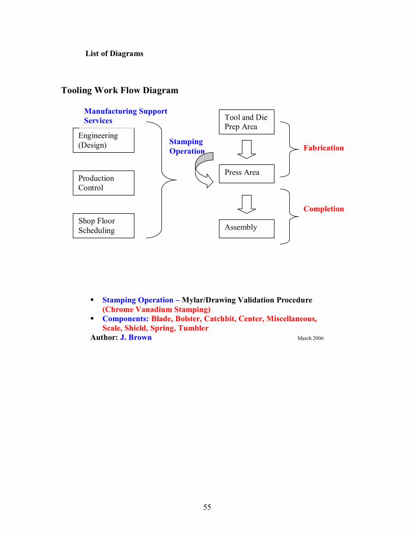
55
List of Diagrams
Tooling Work Flow Diagram
Engineering (Design)
Tool and Die Prep Area
Press Area
Assembly
Completion
Manufacturing Support Services
Stamping Operation Fabrication
! Stamping Operation � Mylar/Drawing Validation Procedure (Chrome Vanadium Stamping) ! Components: Blade, Bolster, Catchbit, Center, Miscellaneous,
Scale, Shield, Spring, Tumbler Author: J. Brown March 2006
Production Control
Shop Floor Scheduling

56
Tool and Die Report Button VBA Code Diagram

57
List of Figures
Figure 1: UML Entity Relationship Diagram pg. 58
Figure 2: Tooling Data Collection Reports pg. 1-6
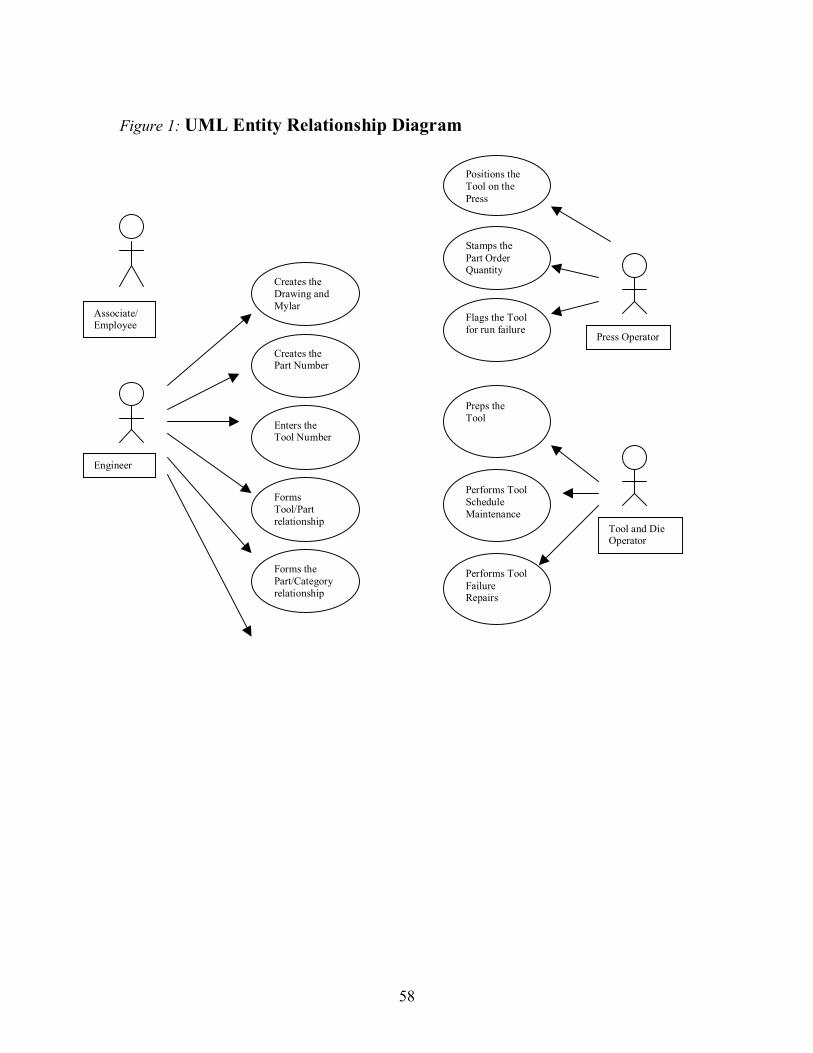
58
Figure 1: UML Entity Relationship Diagram
Associate/ Employee
Engineer
Tool and Die Operator
Press Operator
Stamps the Part Order Quantity
Flags the Tool for run failure
Preps the Tool
Performs Tool Schedule Maintenance
Performs Tool Failure Repairs
Creates the Part Number
Enters the Tool Number
Forms Tool/Part relationship
Forms the Part/Category relationship
Creates the Drawing and Mylar
Positions the Tool on the Press
59
Work Cited
Christensen, Mark J. & Thayer, Richard H. (2001). The Project Manager�s Guide to Software Engineering�s Best Practices. Pg. 188. Los Alamitos, CA: IEEE Computer Society. Case Cutlery (n.d.), Blades & Steel: The Famous Case XX Trademark. Retrieved March 2006.http://www.wrcase.com/info/collecting/blades2.php Case Cutlery (n.d.), About Case. Retrieved March 2006 http://www.wrcase.com/about_case/ Case Cutlery (n.d.), Anatomy of a Case Knife. Retrieved March 2006 http://www.wrcase.com/info/collecting/anatomy.jpg Case Cutlery (n.d.), How to Identify Case Knife Patterns. Retrieved March 2006 http://www.wrcase.com/info/collecting/tang.php Case Cutlery (n.d.), Tails and Traditions. Retrieved March 2006 http://www.wrcase.com/tales_&_traditions/ Case Cutlery (n.d.), Tang Logo Stamp. Retrieved March 2006 http://www.wrcase.com/info/collecting/dating/year1.php# Case Cutlery (n.d.), What Makes Case Different. Retrieved March 2006 http://www.wrcase.com/info/collecting/different.php Cozy Camping Online catalog (n.d.), Single Blade Pocket Knife � online Cozy Camping catalog. Retrieved March 2006 http://www.cozycamping.net/camping-gear-4500.html
Nijkerk, Alfred (November 5, 2004). Market Analysis: Volatility Continues to Dominate the Nickel Scene, Retrieved March 2006 http://www.recyclinginternational.com/pdf_marketreports/MA_Nickel_S_1104.pdf#search='chrome%20vanadium%20stainless%20steel
W.R. Case & Sons Cutlery Company (2002), W.R. Case & Sons Cutlery Company 2002 Catalog: How to determine the year of a Case knife, pg 46.
60
Bibliography
American Edge (2006),Jaysknives.com �A Cut Above the Rest�, Retrieved March 2006 http://www.jaysknives.com/case_1.htm A dealer catalog that sells Case knives and elaborates on the chrome vanadium blades. Case Cutlery (n.d.), About Case. Retrieved March 2006 http://www.wrcase.com/about_case/ Case Cutlery (n.d.), Anatomy of a Case Knife. Retrieved March 2006 http://www.wrcase.com/info/collecting/anatomy.jpg Article describes the parts of a Case knife. Case Cutlery (n.d.), Blades & Steel: The Famous Case XX Trademark. Retrieved March 2006.http://www.wrcase.com/info/collecting/blades2.php Article describes the steel materials & the origin of the XX trademark. Case Cutlery (n.d.), Case Club History. Retrieved March 2006 http://www.wrcase.com/ccc/history.php Article summarizes the Case Collector Club origin & history. Case Cutlery (n.d.), How to Identify Case Knife Patterns. Retrieved March 2006 http://www.wrcase.com/info/collecting/tang.php Article describes the definition of the knife pattern Case Cutlery (n.d.), Knives. Retrieved March 2006 http://www.wrcase.com/knives Describes Case knife products Case Cutlery (n.d.), Tang Logo Stamp. Retrieved March 2006 http://www.wrcase.com/info/collecting/dating/year1.php# Article contains illustrations of the Tang-Logo Stamp on Case blades as the years have progressed. Case Cutlery (n.d.), Tails and Traditions. Retrieved March 2006 http://www.wrcase.com/tales_&_traditions/ Describes the origin of W.R. Case & Sons Cutlery Company. Case Cutlery (n.d.), What Makes Case Different. Retrieved March 2006 http://www.wrcase.com/info/collecting/different.php Article highlights distinguishing Case Cutlery and product features. Cozy Camping Online catalog (n.d.), Single Blade Pocket Knife � online Cozy Camping catalog. Retrieved March 2006 http://www.cozycamping.net/camping-gear-4500.html
61
Christensen, Mark J. & Thayer, Richard H. (2001). The Project Manager�s Guide to Software Engineering�s Best Practices. Los Alamitos, CA: IEEE Computer Society. Presents best practices of project management including Life Cycle software development methods. National Institute of Standards and Technology (n.d.), Technology Services Standard Reference Materials. Retrieved March 2006. http://ts.nist.gov/ts/htdocs/230/232/ARCHIVED_CERTIFICATES/archived_certificates.htm Bureau of Standards Article contains descriptions about chrome vanadium steel. References edge-holding ability.
Nijkerk, Alfred. (December 1, 2004), Market Analysis: Nickel and Stainless on the Increase Again, Retrieved March 2006 http://www.recyclinginternational.com/pdf_marketreports/MA_Stainless_1204.pdf#search='chrome%20vanadium%20stainless%20steel Describes the stainless steel increase in prices for acquisition.
Nijkerk, Alfred (November 5, 2004). Market Analysis: Volatility Continues to Dominate the Nickel Scene, Retrieved March 2006 http://www.recyclinginternational.com/pdf_marketreports/MA_Nickel_S_1104.pdf#search='chrome%20vanadium%20stainless%20steel. Describes the volatile market for metal raw materials.
Project Management Institute (2004), A Guide to the Project Management Body of Knowledge 3rd Edition, Newton Square, PA: Project Management Institute. (PMBOK) Description of guidelines and recommendations for project management. Talmadge, Joe (May 1998), All About Steel & Alloys. Retrieved March 2006 http://www.ebladestore.com/articles/steel-alloys.shtml Article discusses stainless steel properties and alloys. Contains descriptions about the hardening principles of steel and its use in the cutlery industry.
Talmadge, Joe (July 1999), Steel FAQ. Retrieved March 2006 http://www.sonic.net/~blade/Info___Links/About_Steel/Steel_FAQ/steel_faq.html. Describes steel compositions and the characteristics the various types yield.
Wikipedia (March 2006), Stainless Steel. Retrieved March 2006 http://en.wikipedia.org/wiki/Stainless_steel. Describes the corrosion properties of stainless steel.
W.R. Case & Sons Cutlery Company (2002), W.R. Case & Sons Cutlery Company 2002 Catalog: How to determine the year of a Case knife, pg 46.
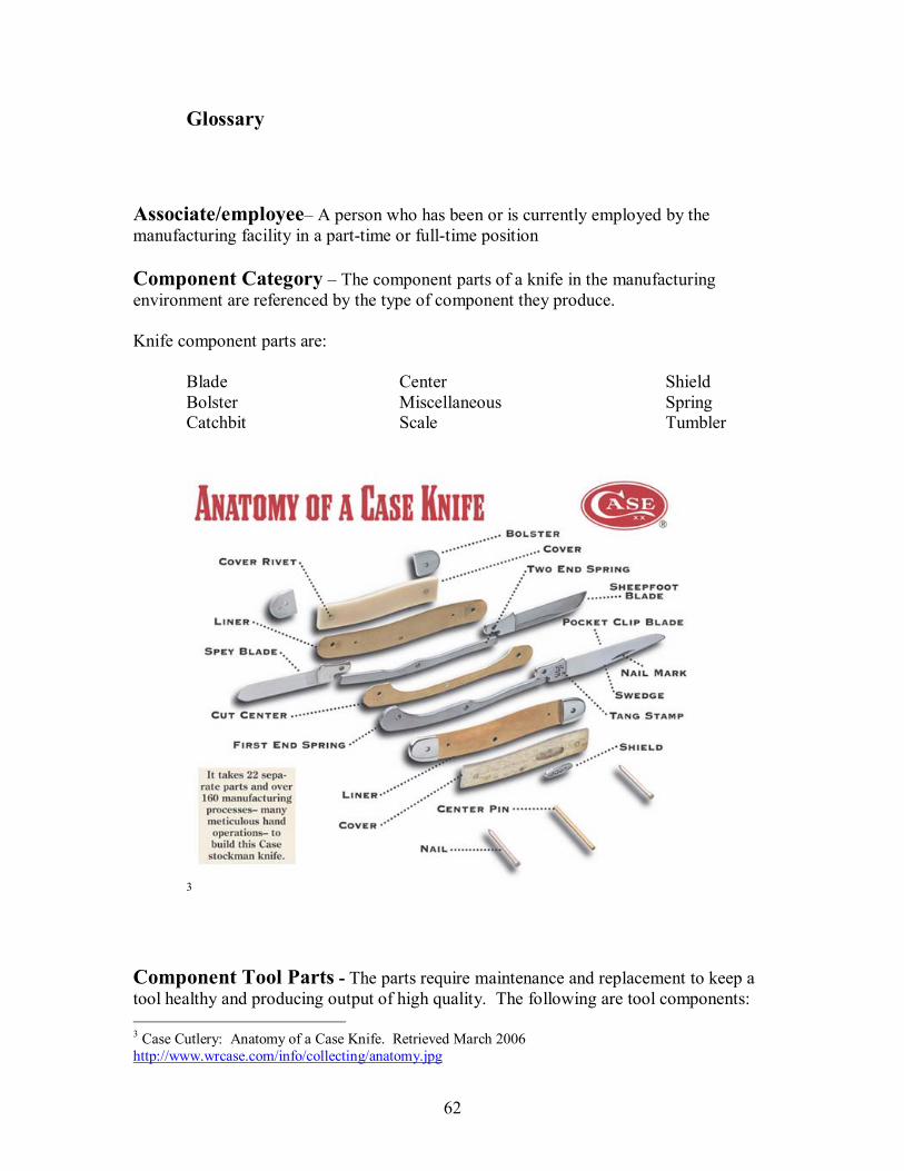
62
Glossary
Associate/employee� A person who has been or is currently employed by the manufacturing facility in a part-time or full-time position Component Category � The component parts of a knife in the manufacturing environment are referenced by the type of component they produce. Knife component parts are:
Blade Center Shield Bolster Miscellaneous Spring Catchbit Scale Tumbler
3
Component Tool Parts - The parts require maintenance and replacement to keep a tool healthy and producing output of high quality. The following are tool components: 3 Case Cutlery: Anatomy of a Case Knife. Retrieved March 2006 http://www.wrcase.com/info/collecting/anatomy.jpg

63
pierce punch pilot pierce die plate thickness gut punch guide rail shave punch die buttons punch retainer dish punch main punch stripper plate
Mapics System � The purchase software used for production scheduling and Enterprise Resource Planning. Mark side/Pile side � Terms that refer to the sides of a scale component part of a knife. One side of a scale is the mark side with the opposite side, the pile side. Master Traveler� The paper copy of the Mapics ERP System production request. Mylar � The drawing of a component part that is printed on paper with a protective coating. This is used on a projector to reflect the outline or profile of a component for the press operator to determine if the part pressed is within specifications. Nail mark � The indentation on a blade that is used to open a completed knife. The styles of nailmarks are: standard (straight) and french cut (curved) Pattern � T4he method of classification of a knife with distinguishing characteristics.
In this example, 6347 is a 47 pattern knife with jigged bone handles and 3 blades.
Pocket/Cap � Terms that refer to the types of punch (es) of a component tool part.
4 Case Cutlery: How to Identify Case Knife Patterns Retrieved March 2006 http://www.wrcase.com/info/collecting/tang.php
64
Prep Operator � An associate/employee known as a Tool and Die maker. They prepare the tools for the press operator. The tool prep guidelines are provided on the Master Traveler documentation Press Operator � An associate/employee that operates a press. They load the raw material on the wheels that feed to the press for the tool to stamp out the component part. Profile � The outline or parameter of a component part punched. Stamps � The standard knife stamps on a blade are the pattern stamp, logo stamp and tang stamp. This is the distinguishing feature that has gain popularity with the W.R. Case & Sons Cutlery product identification mark. Stainless Steel � Raw material used for stamping knife component parts. The rolls of stainless steel are fed thru the press over the tool that has been prepped to produced a specific component. X-Axis / Y-Axis � The coordinates for determining the location of a hole punch on a component part. The fluctuations in the values for the markings indicates a problem for the engineers to investigate. The hole (s) must align in order to assemble properly in the final product.
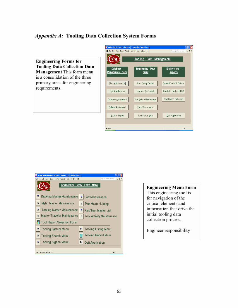
65
Appendix A: Tooling Data Collection System Forms
Engineering Forms for Tooling Data Collection Data Management This form menu is a consolidation of the three primary areas for engineering requirements.
Engineering Menu Form This engineering tool is for navigation of the critical elements and information that drive the initial tooling data collection process. Engineer responsibility
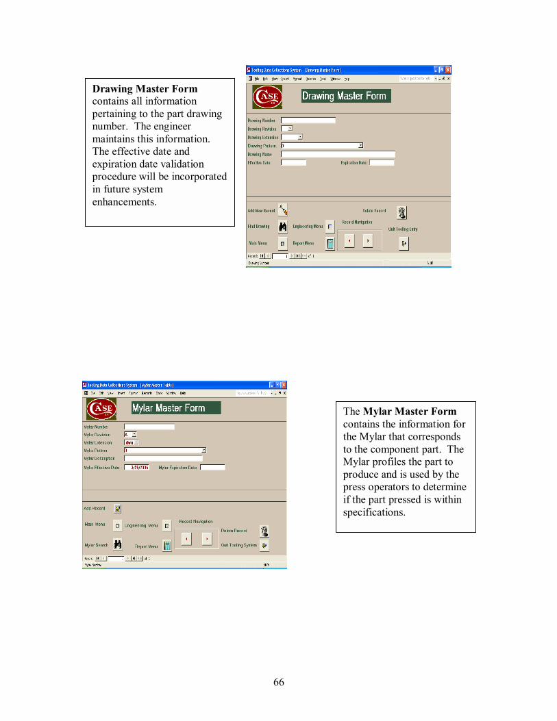
66
The Mylar Master Form contains the information for the Mylar that corresponds to the component part. The Mylar profiles the part to produce and is used by the press operators to determine if the part pressed is within specifications.
Drawing Master Form contains all information pertaining to the part drawing number. The engineer maintains this information. The effective date and expiration date validation procedure will be incorporated in future system enhancements.
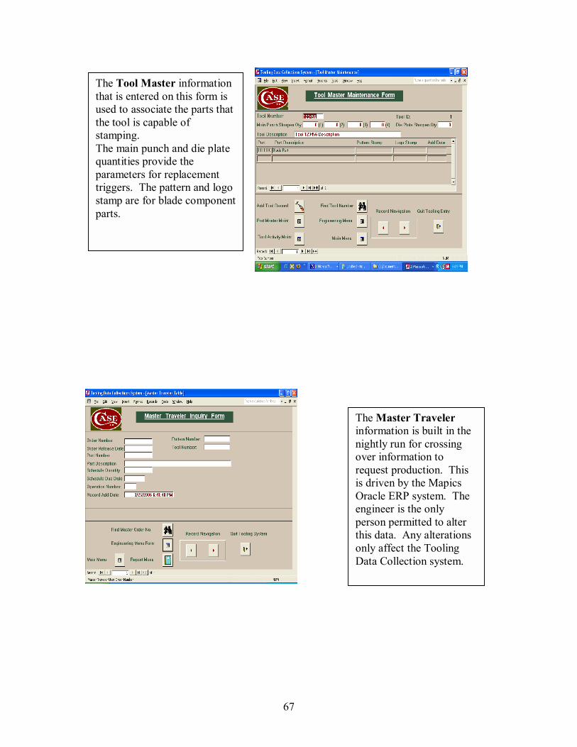
67
The Tool Master information that is entered on this form is used to associate the parts that the tool is capable of stamping. The main punch and die plate quantities provide the parameters for replacement triggers. The pattern and logo stamp are for blade componentparts.
The Master Traveler information is built in the nightly run for crossing over information to request production. This is driven by the Mapics Oracle ERP system. The engineer is the only person permitted to alter this data. Any alterations only affect the Tooling Data Collection system.
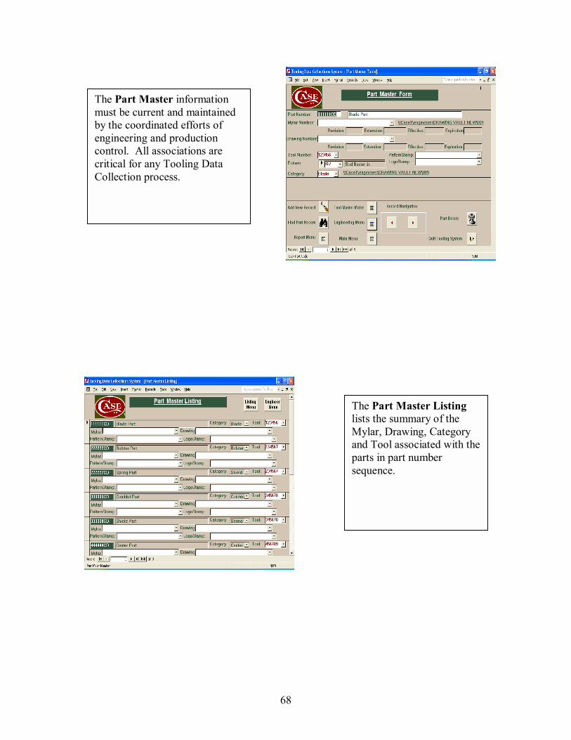
68
The Part Master information must be current and maintained by the coordinated efforts of engineering and production control. All associations are critical for any Tooling Data Collection process.
The Part Master Listing lists the summary of the Mylar, Drawing, Category and Tool associated with the parts in part number sequence.
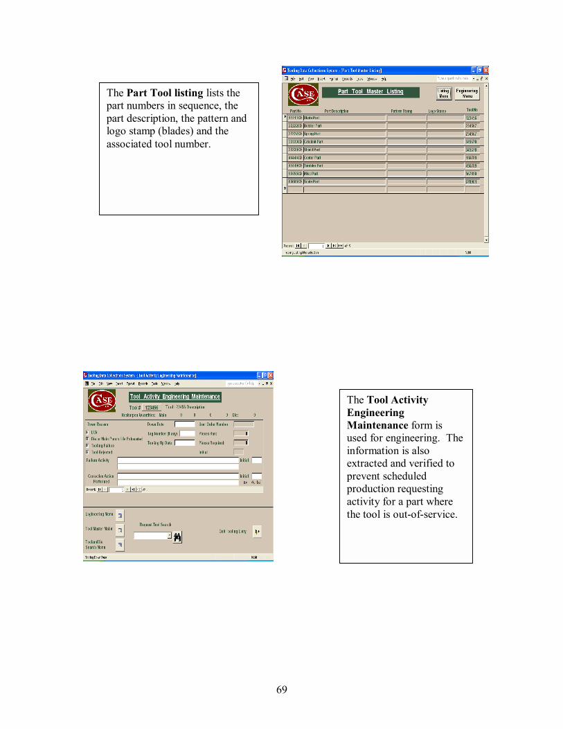
69
The Part Tool listing lists the part numbers in sequence, the part description, the pattern and logo stamp (blades) and the associated tool number.
The Tool Activity Engineering Maintenance form is used for engineering. The information is also extracted and verified to prevent scheduled production requesting activity for a part where the tool is out-of-service.
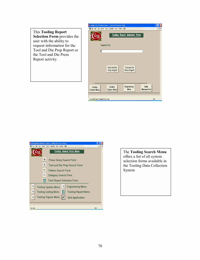
70
This Tooling Report Selection Form provides theuser with the ability to request information for the Tool and Die Prep Report or the Tool and Die Press Report activity.
The Tooling Search Menu offers a list of all system selection forms available in the Tooling Data Collection System

71
The Press Setup Search Form provides the press operators with the ability to progress to the press setup using the Master Traveler Order number, or search Press activity to-date by Pattern number or search Press Tool Activity by Tool number.
This form demonstration illustrates the available patterns for Press search activity.
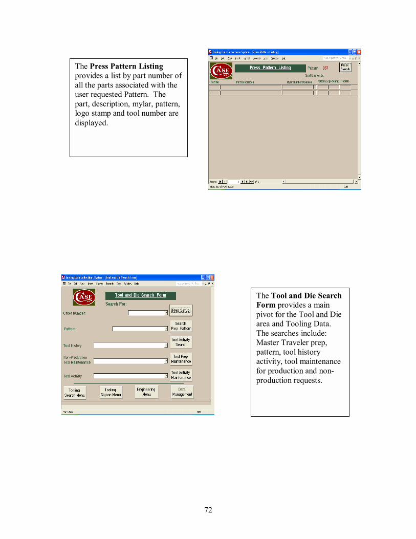
72
The Press Pattern Listing provides a list by part number of all the parts associated with the user requested Pattern. The part, description, mylar, pattern, logo stamp and tool number are displayed.
The Tool and Die Search Form provides a main pivot for the Tool and Die area and Tooling Data. The searches include: Master Traveler prep, pattern, tool history activity, tool maintenance for production and non-production requests.
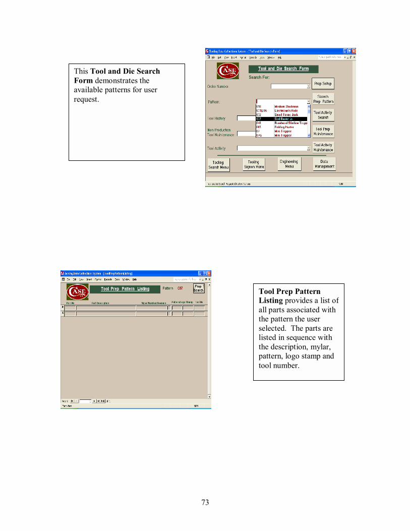
73
This Tool and Die Search Form demonstrates the available patterns for user request.
Tool Prep Pattern Listing provides a list of all parts associated with the pattern the user selected. The parts are listed in sequence with the description, mylar, pattern, logo stamp and tool number.
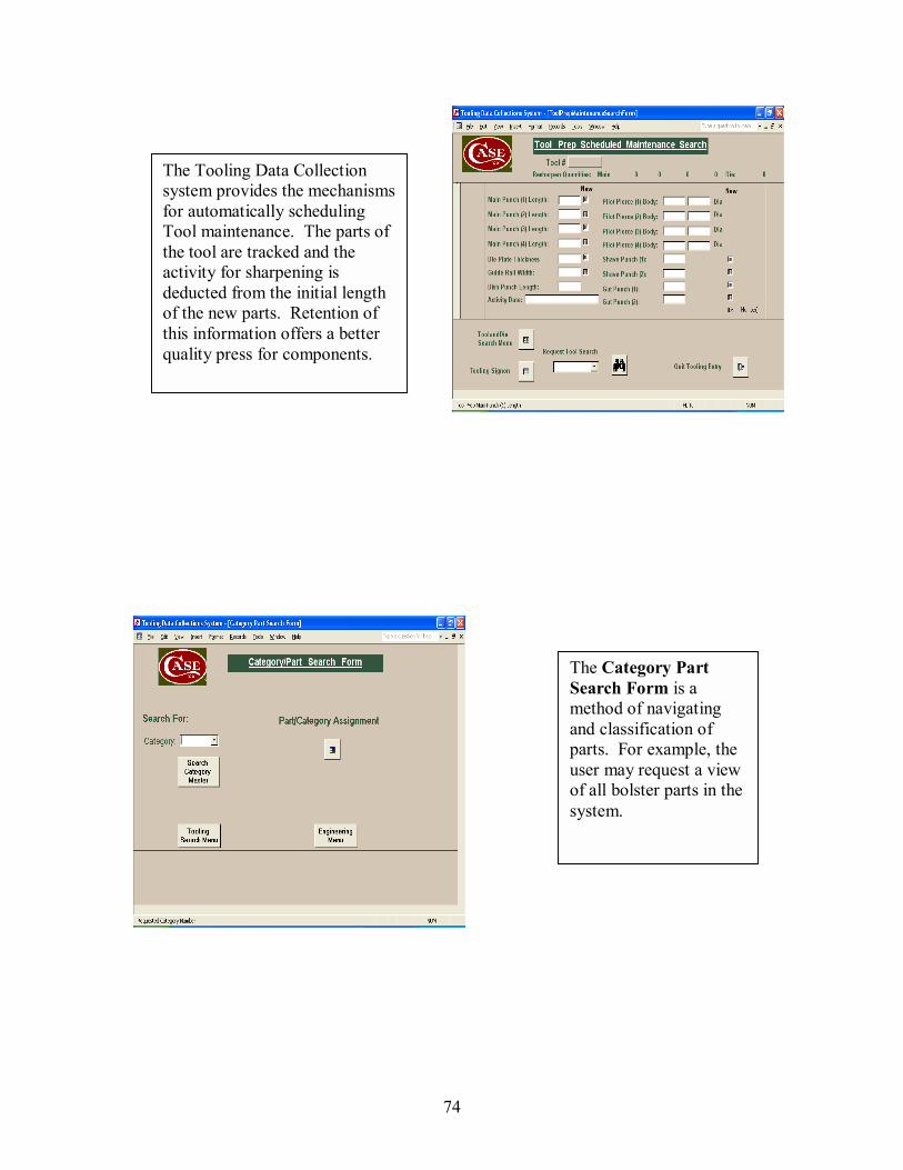
74
The Tooling Data Collection system provides the mechanisms for automatically scheduling Tool maintenance. The parts of the tool are tracked and the activity for sharpening is deducted from the initial length of the new parts. Retention of this information offers a better quality press for components.
The Category Part Search Form is a method of navigating and classification of parts. For example, the user may request a view of all bolster parts in the system.
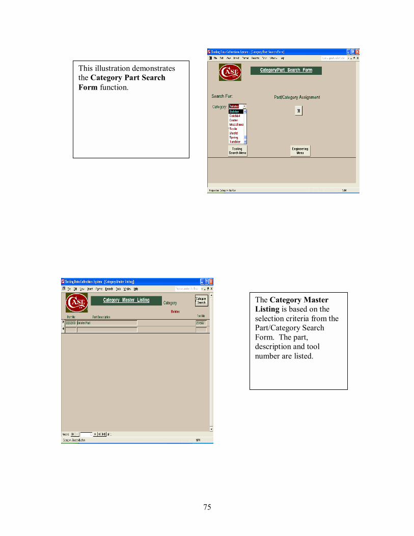
75
This illustration demonstrates the Category Part Search Form function.
The Category Master Listing is based on the selection criteria from the Part/Category Search Form. The part, description and tool number are listed.
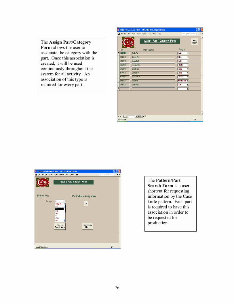
76
The Assign Part/Category Form allows the user to associate the category with the part. Once this association is created, it will be used continuously throughout the system for all activity. An association of this type is required for every part.
The Pattern/Part Search Form is a user shortcut for requesting information by the Case knife pattern. Each part is required to have this association in order to be requested for production.
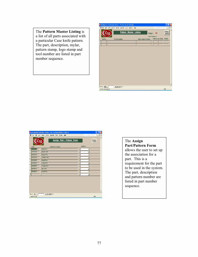
77
The Pattern Master Listing is a list of all parts associated with a particular Case knife pattern. The part, description, mylar, pattern stamp, logo stamp and tool number are listed in part number sequence.
The Assign Part/Pattern Form allows the user to set up the association for a part. This is a requirement for the part to be used in the system. The part, description and pattern number are listed in part number sequence.
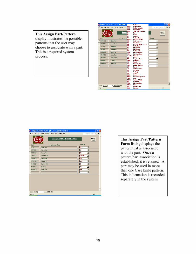
78
This Assign Part/Pattern display illustrates the possible patterns that the user may choose to associate with a part. This is a required system process.
This Assign Part/Pattern Form listing displays the pattern that is associated with the part. Once a pattern/part association is established, it is retained. A part may be used in more than one Case knife pattern. This information is recorded separately in the system.
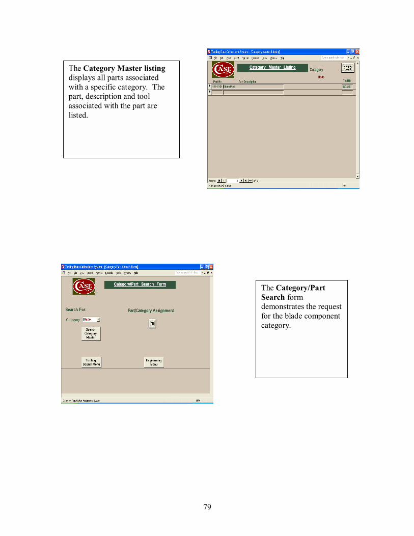
79
The Category Master listing displays all parts associated with a specific category. The part, description and tool associated with the part are listed.
The Category/Part Search form demonstrates the request for the blade component category.
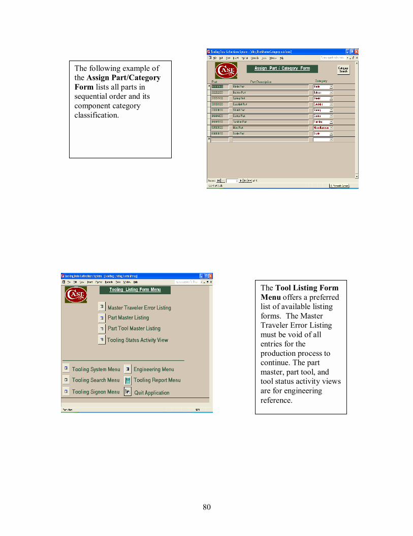
80
The following example of the Assign Part/Category Form lists all parts in sequential order and its component category classification.
The Tool Listing Form Menu offers a preferred list of available listing forms. The Master Traveler Error Listing must be void of all entries for the production process to continue. The part master, part tool, and tool status activity views are for engineering reference.
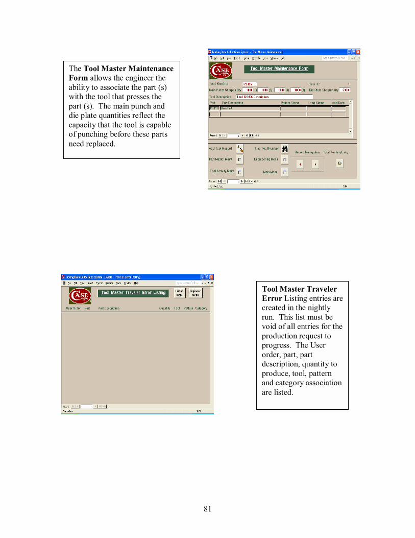
81
The Tool Master Maintenance Form allows the engineer the ability to associate the part (s) with the tool that presses the part (s). The main punch and die plate quantities reflect the capacity that the tool is capable of punching before these parts need replaced.
Tool Master Traveler Error Listing entries are created in the nightly run. This list must be void of all entries for the production request to progress. The User order, part, part description, quantity to produce, tool, pattern and category association are listed.
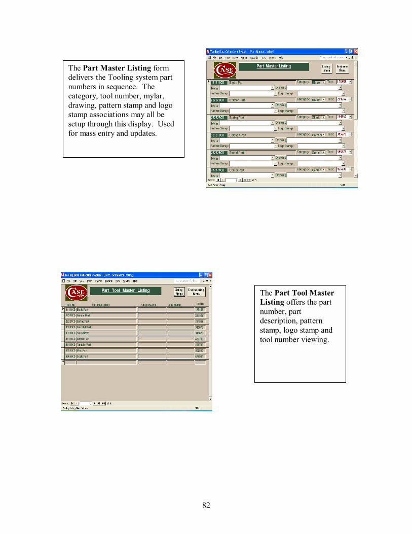
82
The Part Master Listing form delivers the Tooling system part numbers in sequence. The category, tool number, mylar, drawing, pattern stamp and logo stamp associations may all be setup through this display. Used for mass entry and updates.
The Part Tool Master Listing offers the part number, part description, pattern stamp, logo stamp and tool number viewing.
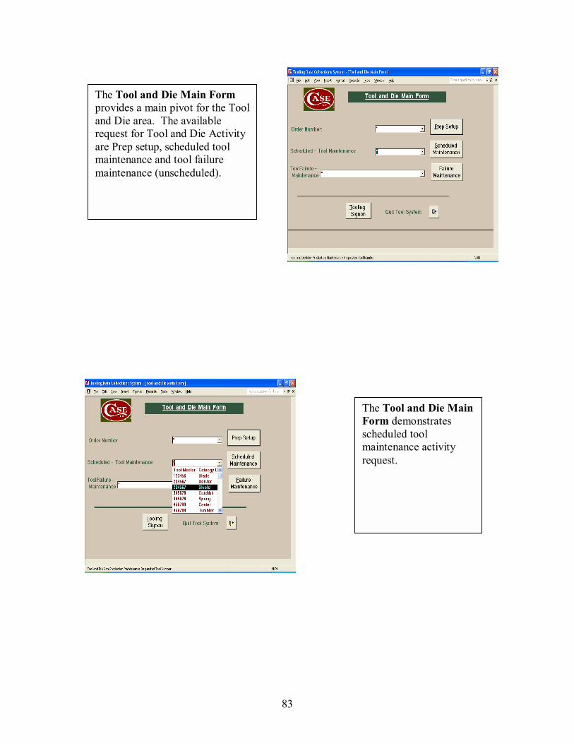
83
The Tool and Die Main Form provides a main pivot for the Tool and Die area. The available request for Tool and Die Activity are Prep setup, scheduled tool maintenance and tool failure maintenance (unscheduled).
The Tool and Die Main Form demonstrates scheduled tool maintenance activity request.
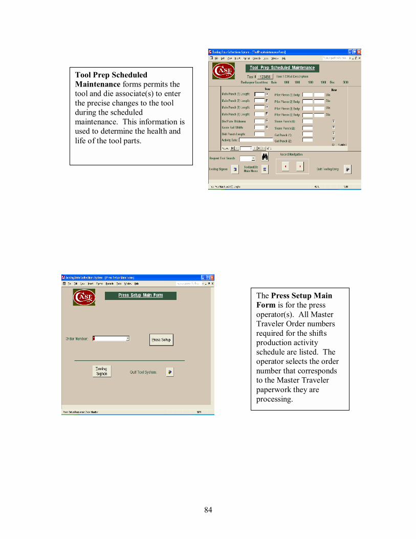
84
Tool Prep Scheduled Maintenance forms permits the tool and die associate(s) to enter the precise changes to the tool during the scheduled maintenance. This information is used to determine the health and life of the tool parts.
The Press Setup Main Form is for the press operator(s). All Master Traveler Order numbers required for the shifts production activity schedule are listed. The operator selects the order number that corresponds to the Master Traveler paperwork they are processing.
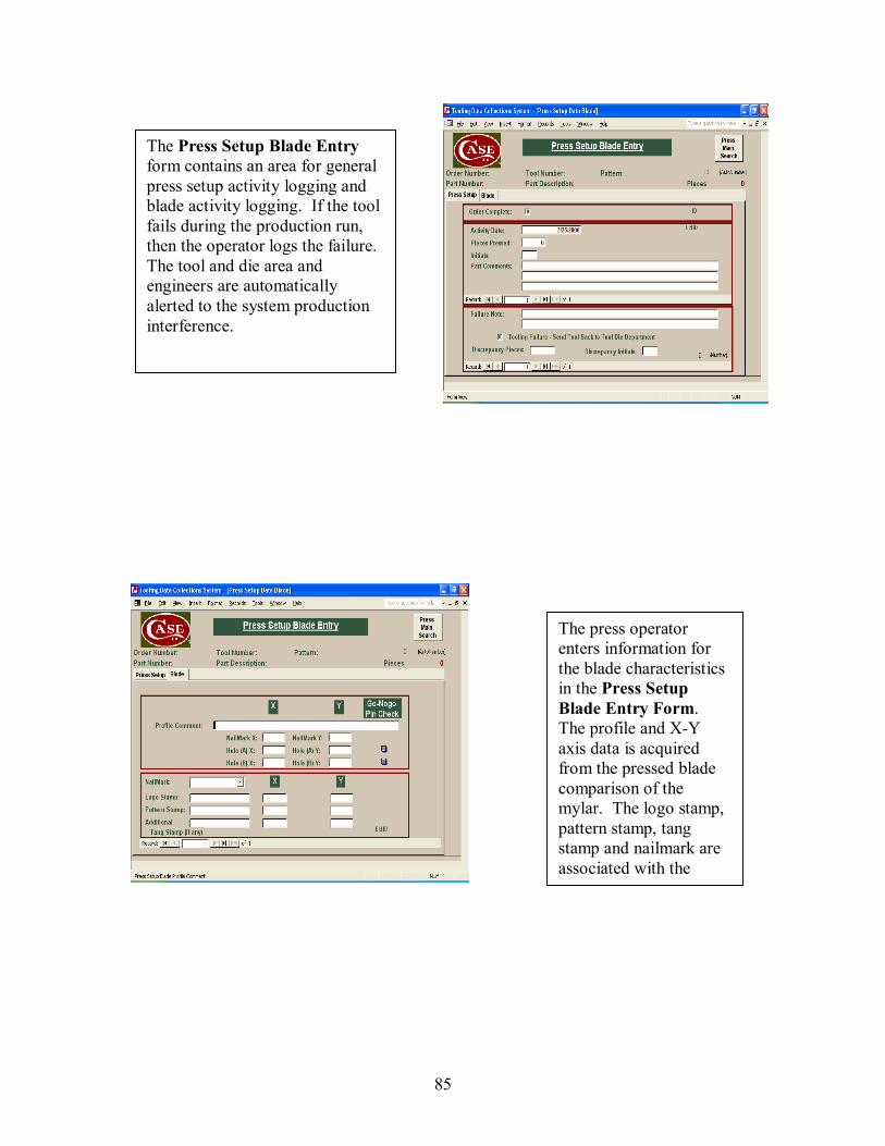
85
The Press Setup Blade Entry form contains an area for general press setup activity logging and blade activity logging. If the tool fails during the production run, then the operator logs the failure. The tool and die area and engineers are automatically alerted to the system production interference.
The press operator enters information for the blade characteristics in the Press Setup Blade Entry Form. The profile and X-Y axis data is acquired from the pressed blade comparison of the mylar. The logo stamp, pattern stamp, tang stamp and nailmark are associated with the
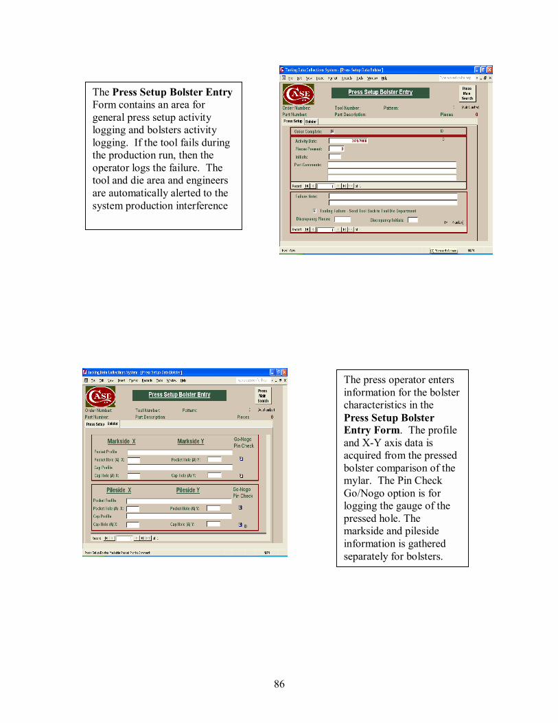
86
The Press Setup Bolster EntryForm contains an area for general press setup activity logging and bolsters activity logging. If the tool fails during the production run, then the operator logs the failure. The tool and die area and engineers are automatically alerted to the system production interference
The press operator enters information for the bolster characteristics in the Press Setup Bolster Entry Form. The profile and X-Y axis data is acquired from the pressed bolster comparison of the mylar. The Pin Check Go/Nogo option is for logging the gauge of the pressed hole. The markside and pileside information is gathered separately for bolsters.
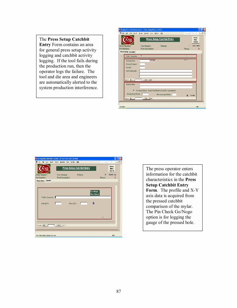
87
The Press Setup Catchbit Entry Form contains an area for general press setup activity logging and catchbit activity logging. If the tool fails during the production run, then the operator logs the failure. The tool and die area and engineers are automatically alerted to the system production interference.
The press operator enters information for the catchbit characteristics in the Press Setup Catchbit Entry Form. The profile and X-Y axis data is acquired from the pressed catchbit comparison of the mylar. The Pin Check Go/Nogo option is for logging the gauge of the pressed hole.
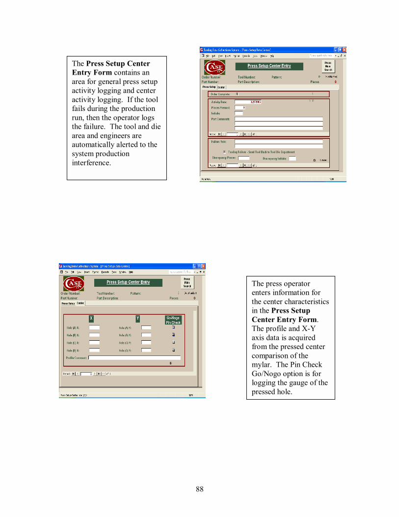
88
The Press Setup Center Entry Form contains an area for general press setup activity logging and center activity logging. If the tool fails during the production run, then the operator logs the failure. The tool and die area and engineers are automatically alerted to the system production interference.
The press operator enters information for the center characteristics in the Press Setup Center Entry Form. The profile and X-Y axis data is acquired from the pressed center comparison of the mylar. The Pin Check Go/Nogo option is for logging the gauge of the pressed hole.
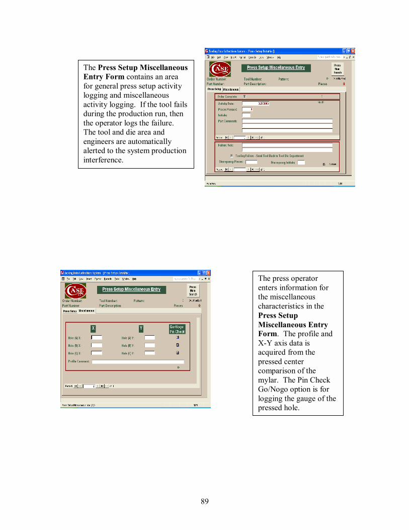
89
The Press Setup Miscellaneous Entry Form contains an area for general press setup activity logging and miscellaneous activity logging. If the tool fails during the production run, then the operator logs the failure. The tool and die area and engineers are automatically alerted to the system production interference.
The press operator enters information for the miscellaneous characteristics in the Press Setup Miscellaneous Entry Form. The profile and X-Y axis data is acquired from the pressed center comparison of the mylar. The Pin Check Go/Nogo option is for logging the gauge of the pressed hole.

90
The Press Setup Scale Entry Form contains an area for general press setup activity logging and scale activity logging. If the tool fails during the production run, then the operator logs the failure. The tool and die area and engineers are automatically alerted to the system production interference.
The press operator enters information for the scale characteristics in the Press Setup Scale Entry Form. The profile and X-Y axis data is acquired from the pressed Scale comparison of the mylar. The Pin Check Go/Nogo option is for logging the gauge of the pressed hole. The markside and pileside information is gathered separately.
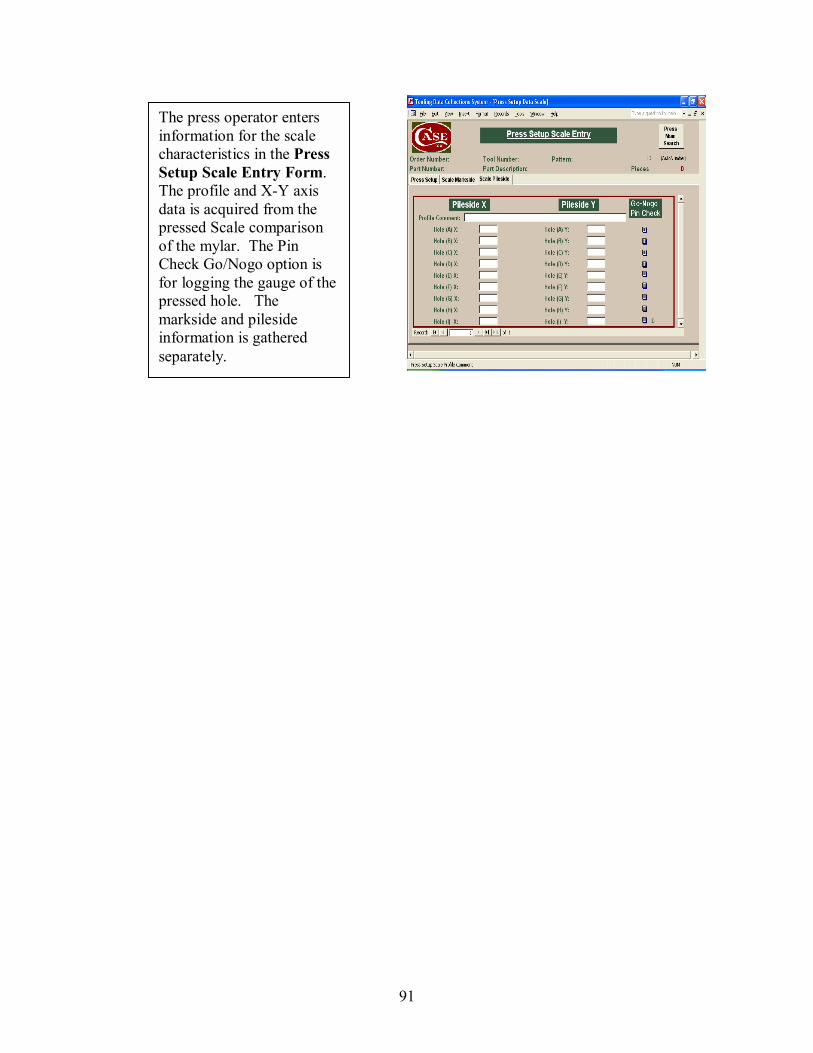
91
The press operator enters information for the scale characteristics in the Press Setup Scale Entry Form. The profile and X-Y axis data is acquired from the pressed Scale comparison of the mylar. The Pin Check Go/Nogo option is for logging the gauge of the pressed hole. The markside and pileside information is gathered separately.

92
The Press Setup Shield Entry Form contains an area for general press setup activity logging and shield activity logging. If the tool fails during the production run, then the operator logs the failure. The tool and die area and engineers are automatically alerted to the system production interference.
The press operator enters information for the shield characteristics in the Press Setup Shield Entry Form. The profile data is acquired from the pressed Shield comparison of the mylar.
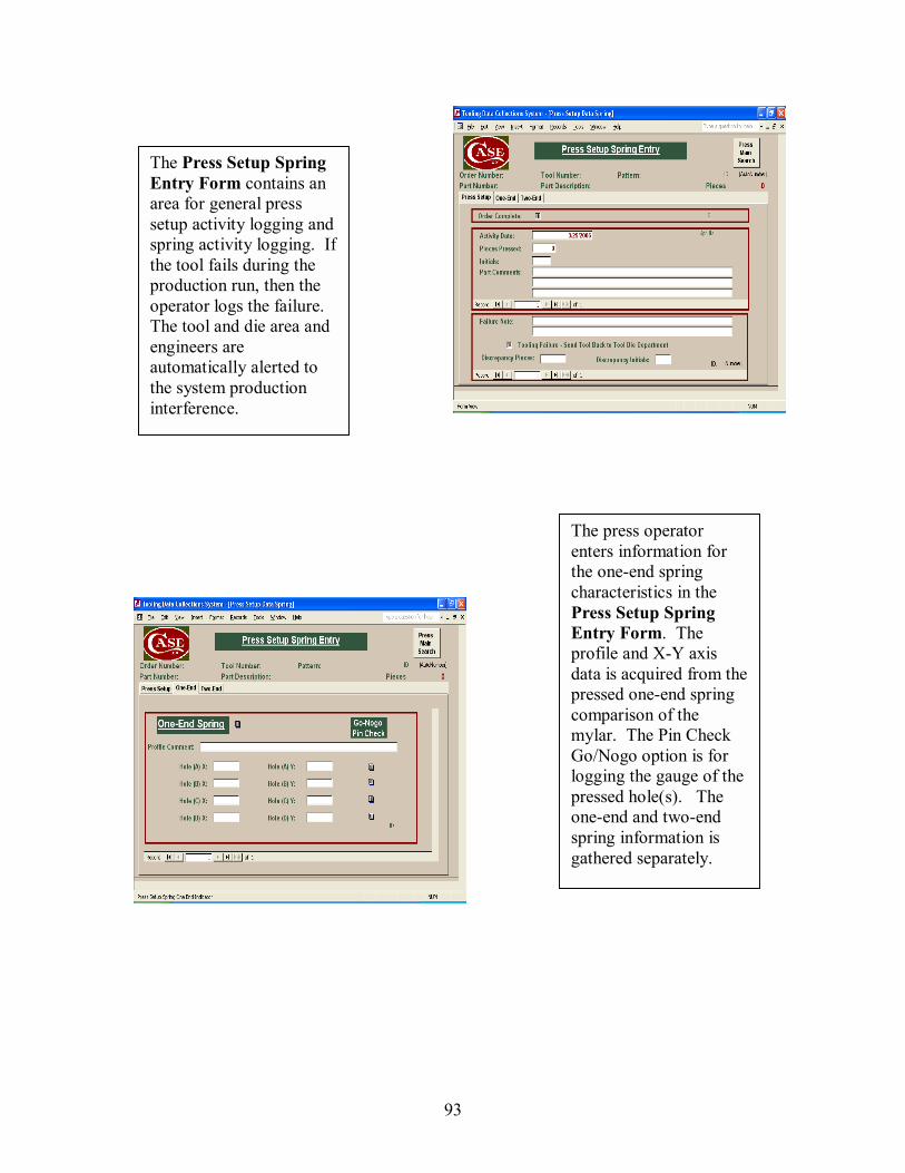
93
The Press Setup Spring Entry Form contains an area for general press setup activity logging and spring activity logging. If the tool fails during the production run, then the operator logs the failure. The tool and die area and engineers are automatically alerted to the system production interference.
The press operator enters information for the one-end spring characteristics in the Press Setup Spring Entry Form. The profile and X-Y axis data is acquired from the pressed one-end spring comparison of the mylar. The Pin Check Go/Nogo option is for logging the gauge of the pressed hole(s). The one-end and two-end spring information is gathered separately.
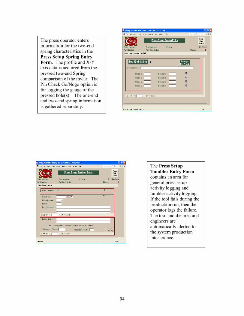
94
The press operator enters information for the two-end spring characteristics in the Press Setup Spring Entry Form. The profile and X-Y axis data is acquired from the pressed two-end Spring comparison of the mylar. The Pin Check Go/Nogo option is for logging the gauge of the pressed hole(s). The one-end and two-end spring information is gathered separately.
The Press Setup Tumbler Entry Form contains an area for general press setup activity logging and tumbler activity logging. If the tool fails during the production run, then the operator logs the failure. The tool and die area and engineers are automatically alerted to the system production interference.
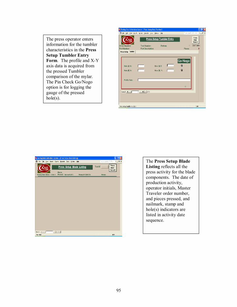
95
The press operator enters information for the tumbler characteristics in the Press Setup Tumbler Entry Form. The profile and X-Y axis data is acquired from the pressed Tumbler comparison of the mylar. The Pin Check Go/Nogo option is for logging the gauge of the pressed hole(s).
The Press Setup Blade Listing reflects all the press activity for the blade components. The date of production activity, operator initials, Master Traveler order number, and pieces pressed, and nailmark, stamp and hole(s) indicators are listed in activity date sequence.
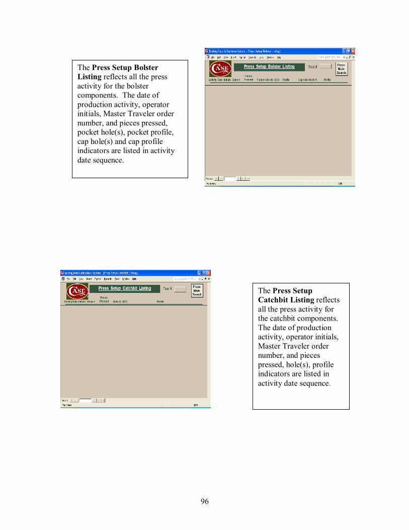
96
The Press Setup Bolster Listing reflects all the press activity for the bolster components. The date of production activity, operator initials, Master Traveler order number, and pieces pressed, pocket hole(s), pocket profile, cap hole(s) and cap profile indicators are listed in activity date sequence.
The Press Setup Catchbit Listing reflects all the press activity for the catchbit components. The date of production activity, operator initials, Master Traveler order number, and pieces pressed, hole(s), profile indicators are listed in activity date sequence.
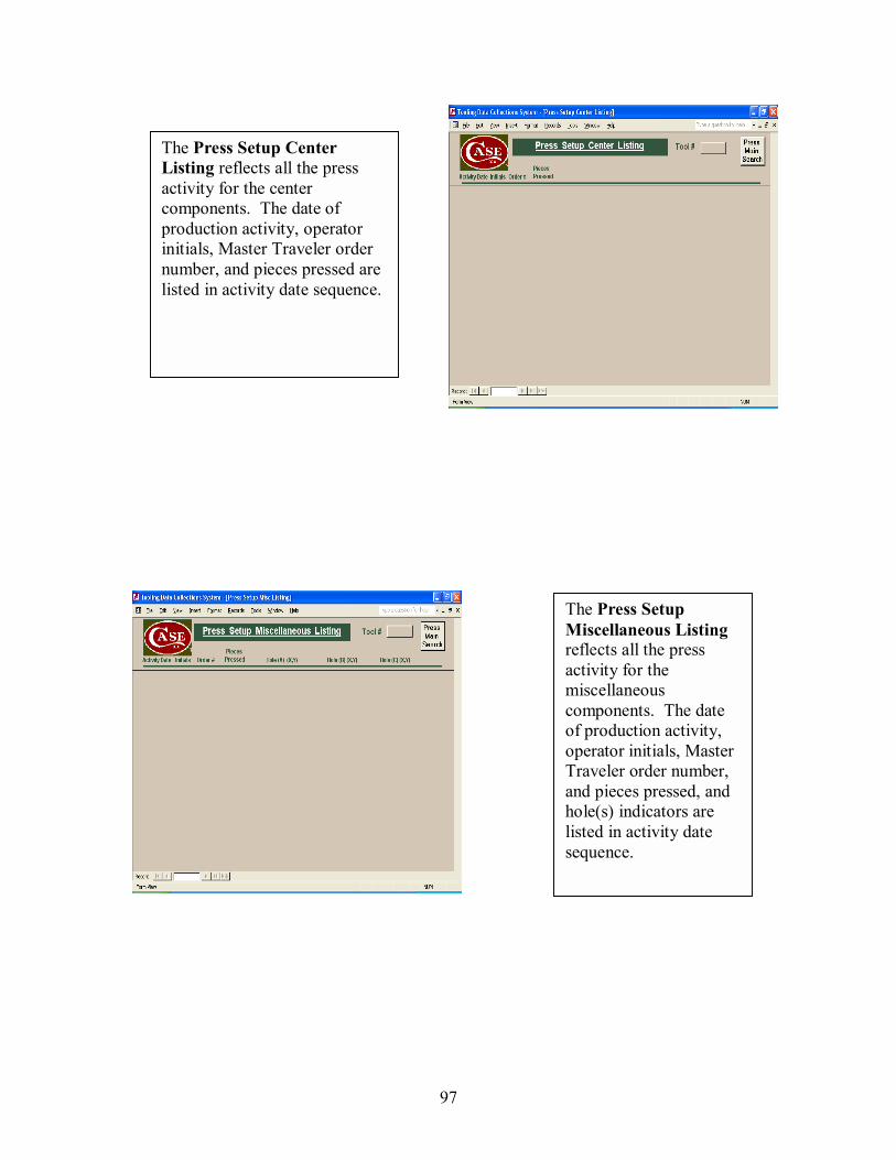
97
The Press Setup Center Listing reflects all the press activity for the center components. The date of production activity, operator initials, Master Traveler order number, and pieces pressed are listed in activity date sequence.
The Press Setup Miscellaneous Listing reflects all the press activity for the miscellaneous components. The date of production activity, operator initials, Master Traveler order number, and pieces pressed, and hole(s) indicators are listed in activity date sequence.
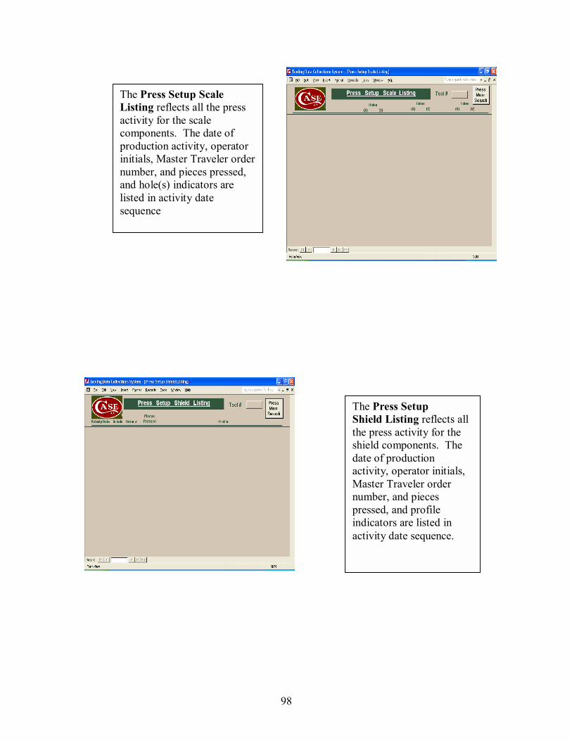
98
The Press Setup Scale Listing reflects all the press activity for the scale components. The date of production activity, operator initials, Master Traveler order number, and pieces pressed, and hole(s) indicators are listed in activity date sequence
The Press Setup Shield Listing reflects all the press activity for the shield components. The date of production activity, operator initials, Master Traveler order number, and pieces pressed, and profile indicators are listed in activity date sequence.

99
The Press Setup Spring Listing reflects all the press activity for the spring components. The date of production activity, operator initials, Master Traveler order number, and pieces pressed, and spring type indicators are listed in activity date sequence.
The Press Setup Tumbler Listing reflects all the press activity for the tumbler components. The date of production activity, operator initials, Master Traveler order number, and pieces pressed, and hole(s) indicators are listed in activity date sequence.

100
The Tool and Die Main Form is for the Tool and Die Associate(s). All Master Traveler Order numbers required for the shifts production activity schedule are listed. The operator selects the order number that corresponds to the Master Traveler paperwork they are processing. The Scheduled and Unscheduled tool maintenance may also be entered from this form.
The Tool Prep operator enters information for the tool characteristics in the Tool and Die Prep Blade Form. All activity that is required to prep the tool is logged. If there is no required change, then the Prep operator will not make a log entry that corresponds to the tool part. The tool failure status is noted for the Prep operator to repair and document required tool changes. The ToGo quantities reflect the expected punch (es) remaining before scheduling tool maintenance.
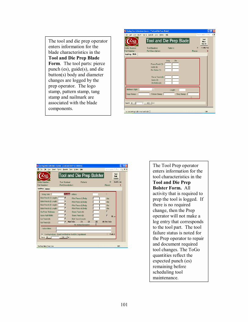
101
The tool and die prep operator enters information for the blade characteristics in the Tool and Die Prep Blade Form. The tool parts: pierce punch (es), guide(s), and die button(s) body and diameter changes are logged by the prep operator. The logo stamp, pattern stamp, tang stamp and nailmark are associated with the blade components.
The Tool Prep operator enters information for the tool characteristics in the Tool and Die Prep Bolster Form. All activity that is required to prep the tool is logged. If there is no required change, then the Prep operator will not make a log entry that corresponds to the tool part. The tool failure status is noted for the Prep operator to repair and document required tool changes. The ToGo quantities reflect the expected punch (es) remaining before scheduling tool maintenance.

102
The Tool Prep operator enters information for the tool characteristics in the Tool and Die Prep Catchbit Form. All activity that is required to prep the tool is logged. If there is no required change, then the Prep operator will not make a log entry that corresponds to the tool part. The tool failure status is noted for the Prep operator to repair and document required tool changes. The ToGo quantities reflect the expected punch (es) remaining before scheduling tool maintenance.
The tool and die prep operator enters information for the bolster characteristics in the Tool and Die Prep Bolster Form. The tool parts: pocket pierce punch (es), pocket punch guide(s), and pocket die button(s), cap pierce punch(es), cap punch guide(s), and cap die button(s) body and diameter changes are logged by the prep operator. The markside and pileside information is gathered separately.

103
The Tool Prep operator enters information for the tool characteristics in the Tool and Die Prep Center Form. All activity that is required to prep the tool is logged. If there is no required change, then the Prep operator will not make a log entry that corresponds to the tool part. The tool failure status is noted for the Prep operator to repair and document required tool changes. The ToGo quantities reflect the expected punch (es) remaining before scheduling tool maintenance.
The tool and die prep operator enters information for the Catchbit characteristics in the Tool and Die Prep Catchbit Form. The tool parts: pierce punch (es), guide(s), and die button(s) body and diameter changes are logged by the prep operator.
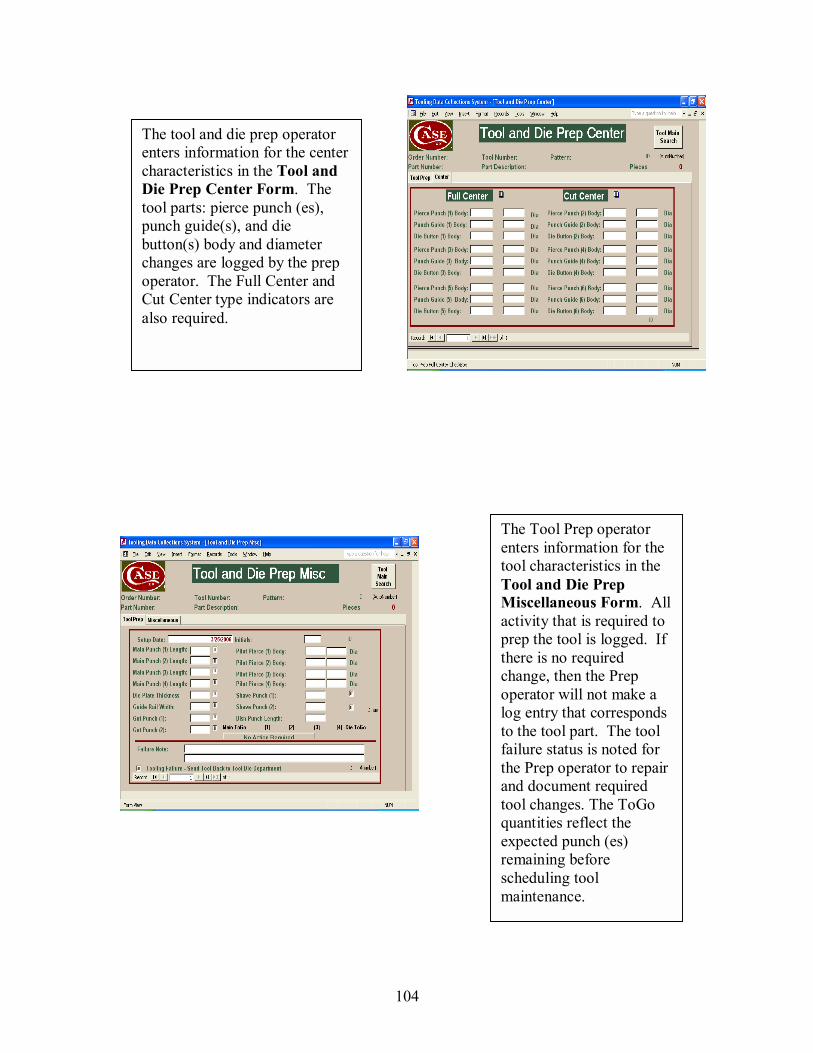
104
The Tool Prep operator enters information for the tool characteristics in the Tool and Die Prep Miscellaneous Form. All activity that is required to prep the tool is logged. If there is no required change, then the Prep operator will not make a log entry that corresponds to the tool part. The tool failure status is noted for the Prep operator to repair and document required tool changes. The ToGo quantities reflect the expected punch (es) remaining before scheduling tool maintenance.
The tool and die prep operator enters information for the center characteristics in the Tool and Die Prep Center Form. The tool parts: pierce punch (es), punch guide(s), and die button(s) body and diameter changes are logged by the prep operator. The Full Center and Cut Center type indicators are also required.
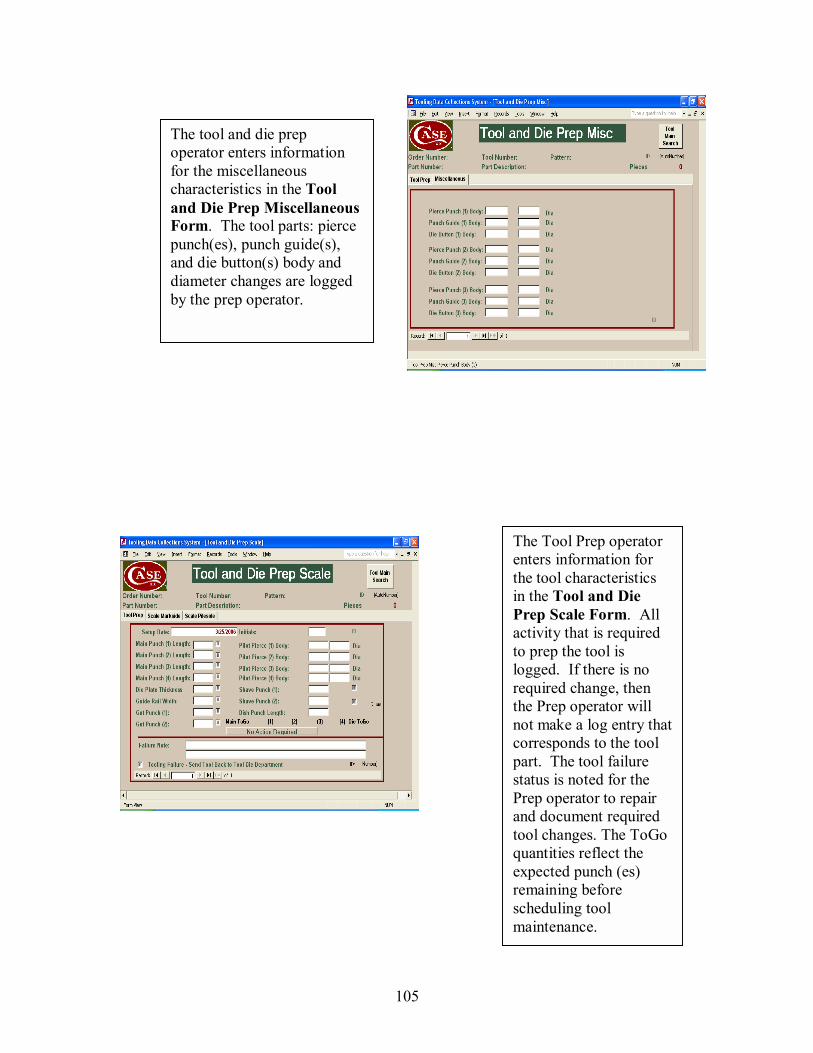
105
The Tool Prep operator enters information for the tool characteristics in the Tool and Die Prep Scale Form. All activity that is required to prep the tool is logged. If there is no required change, then the Prep operator will not make a log entry that corresponds to the tool part. The tool failure status is noted for the Prep operator to repair and document required tool changes. The ToGo quantities reflect the expected punch (es) remaining before scheduling tool maintenance.
The tool and die prep operator enters information for the miscellaneous characteristics in the Tool and Die Prep Miscellaneous Form. The tool parts: pierce punch(es), punch guide(s), and die button(s) body and diameter changes are logged by the prep operator.
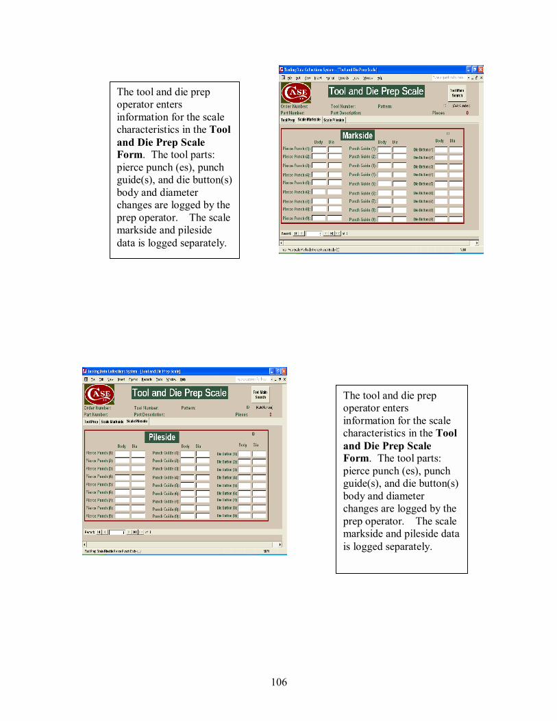
106
The tool and die prep operator enters information for the scale characteristics in the Tool and Die Prep Scale Form. The tool parts: pierce punch (es), punch guide(s), and die button(s) body and diameter changes are logged by the prep operator. The scale markside and pileside data is logged separately.
The tool and die prep operator enters information for the scale characteristics in the Tool and Die Prep Scale Form. The tool parts: pierce punch (es), punch guide(s), and die button(s) body and diameter changes are logged by the prep operator. The scale markside and pileside data is logged separately.
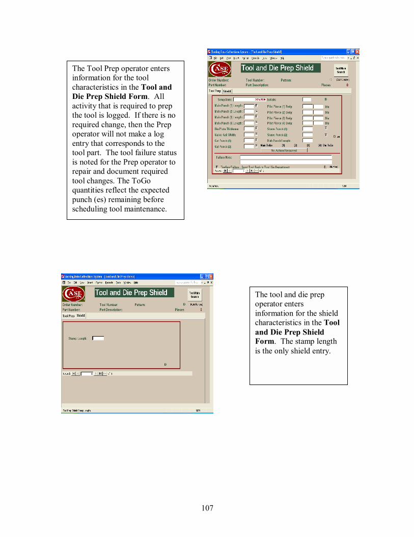
107
The Tool Prep operator enters information for the tool characteristics in the Tool and Die Prep Shield Form. All activity that is required to prep the tool is logged. If there is no required change, then the Prep operator will not make a log entry that corresponds to the tool part. The tool failure status is noted for the Prep operator to repair and document required tool changes. The ToGo quantities reflect the expected punch (es) remaining before scheduling tool maintenance.
The tool and die prep operator enters information for the shield characteristics in the Tool and Die Prep Shield Form. The stamp length is the only shield entry.
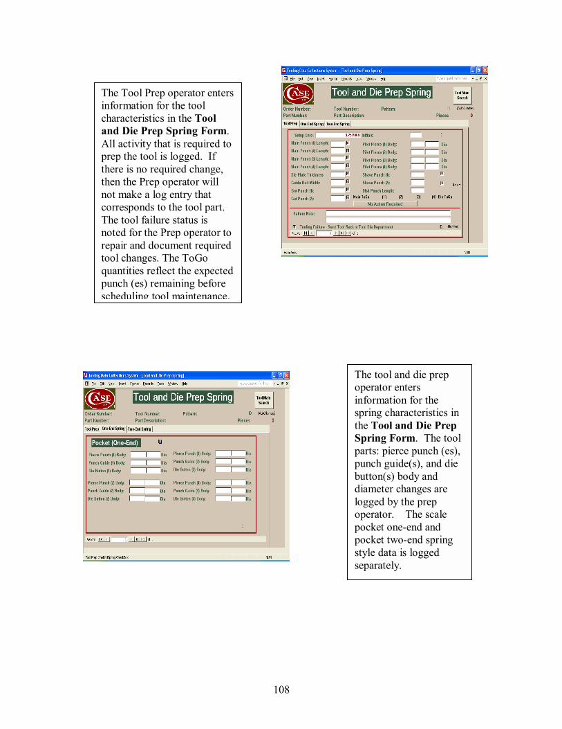
108
The Tool Prep operator enters information for the tool characteristics in the Tool and Die Prep Spring Form. All activity that is required to prep the tool is logged. If there is no required change, then the Prep operator will not make a log entry that corresponds to the tool part. The tool failure status is noted for the Prep operator to repair and document required tool changes. The ToGo quantities reflect the expected punch (es) remaining before scheduling tool maintenance.
The tool and die prep operator enters information for the spring characteristics in the Tool and Die Prep Spring Form. The tool parts: pierce punch (es), punch guide(s), and die button(s) body and diameter changes are logged by the prep operator. The scale pocket one-end and pocket two-end spring style data is logged separately.
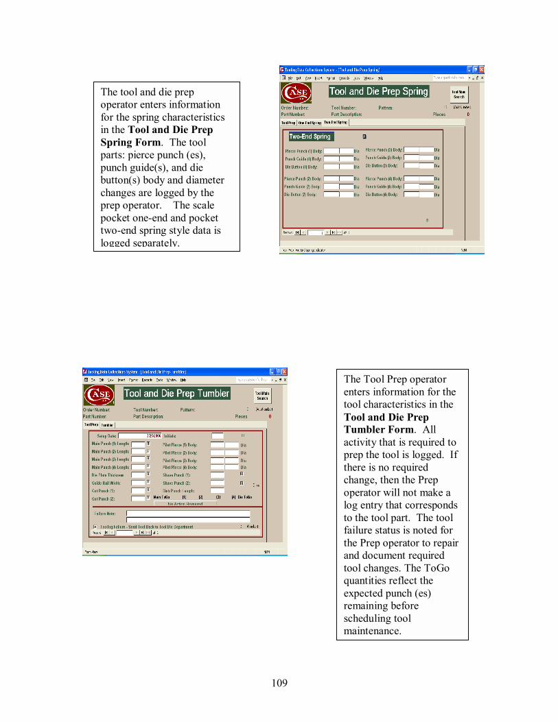
109
The Tool Prep operator enters information for the tool characteristics in the Tool and Die Prep Tumbler Form. All activity that is required to prep the tool is logged. If there is no required change, then the Prep operator will not make a log entry that corresponds to the tool part. The tool failure status is noted for the Prep operator to repair and document required tool changes. The ToGo quantities reflect the expected punch (es) remaining before scheduling tool maintenance.
The tool and die prep operator enters information for the spring characteristics in the Tool and Die Prep Spring Form. The tool parts: pierce punch (es), punch guide(s), and die button(s) body and diameter changes are logged by the prep operator. The scale pocket one-end and pocket two-end spring style data is logged separately.
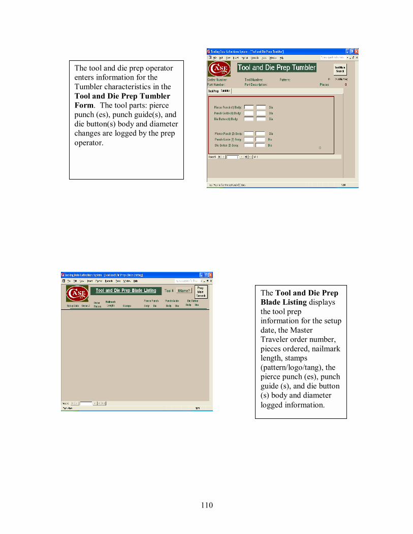
110
The tool and die prep operator enters information for the Tumbler characteristics in the Tool and Die Prep Tumbler Form. The tool parts: pierce punch (es), punch guide(s), and die button(s) body and diameter changes are logged by the prep operator.
The Tool and Die Prep Blade Listing displays the tool prep information for the setup date, the Master Traveler order number, pieces ordered, nailmark length, stamps (pattern/logo/tang), the pierce punch (es), punch guide (s), and die button (s) body and diameter logged information.
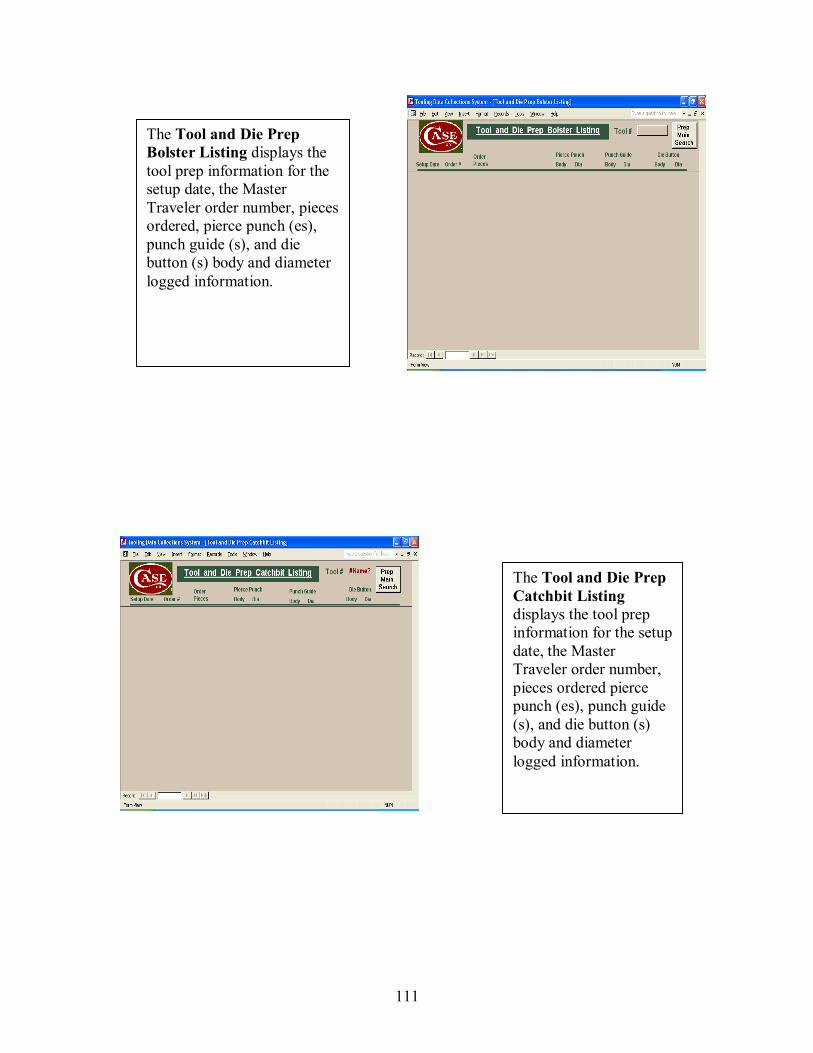
111
The Tool and Die Prep Bolster Listing displays the tool prep information for the setup date, the Master Traveler order number, pieces ordered, pierce punch (es), punch guide (s), and die button (s) body and diameter logged information.
The Tool and Die Prep Catchbit Listing displays the tool prep information for the setup date, the Master Traveler order number, pieces ordered pierce punch (es), punch guide (s), and die button (s) body and diameter logged information.
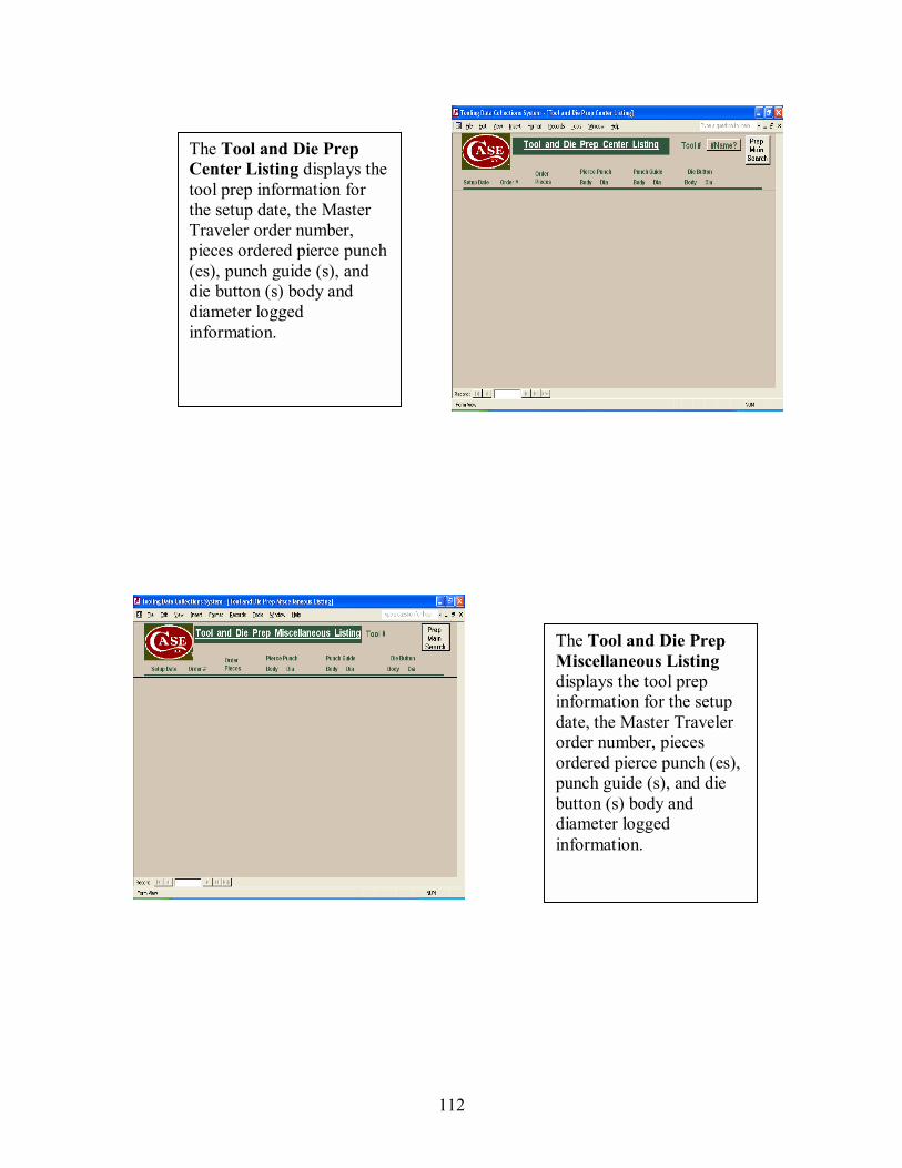
112
The Tool and Die Prep Center Listing displays the tool prep information for the setup date, the Master Traveler order number, pieces ordered pierce punch (es), punch guide (s), and die button (s) body and diameter logged information.
The Tool and Die Prep Miscellaneous Listing displays the tool prep information for the setup date, the Master Traveler order number, pieces ordered pierce punch (es), punch guide (s), and die button (s) body and diameter logged information.
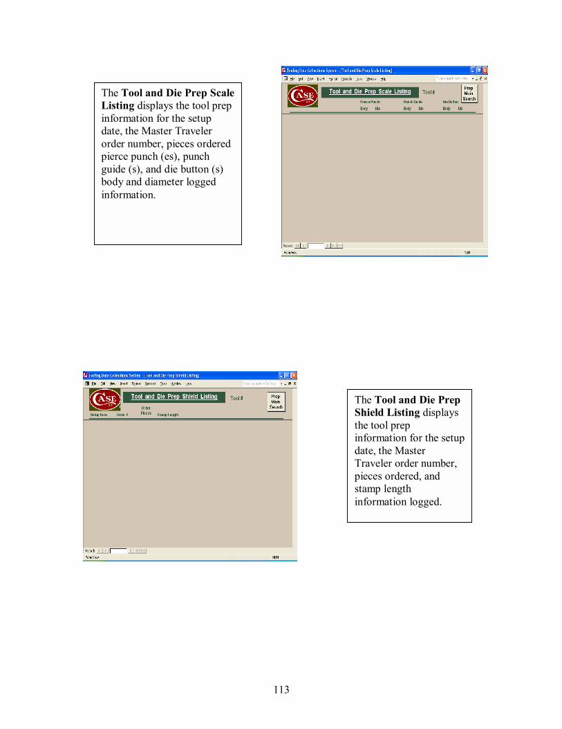
113
The Tool and Die Prep Scale Listing displays the tool prep information for the setup date, the Master Traveler order number, pieces ordered pierce punch (es), punch guide (s), and die button (s) body and diameter logged information.
The Tool and Die Prep Shield Listing displays the tool prep information for the setup date, the Master Traveler order number, pieces ordered, and stamp length information logged.
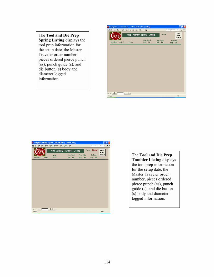
114
The Tool and Die Prep Spring Listing displays the tool prep information for the setup date, the Master Traveler order number, pieces ordered pierce punch (es), punch guide (s), and die button (s) body and diameter logged information.
The Tool and Die Prep Tumbler Listing displays the tool prep information for the setup date, the Master Traveler order number, pieces ordered pierce punch (es), punch guide (s), and die button (s) body and diameter logged information.
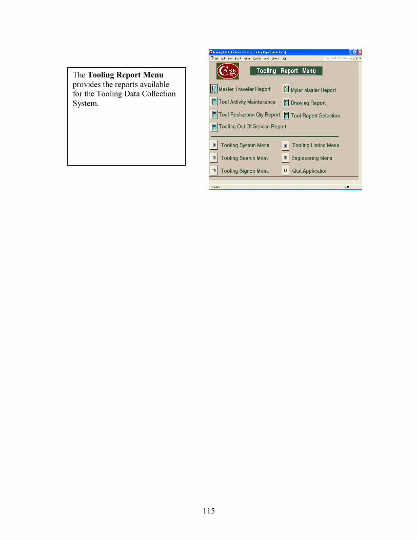
115
The Tooling Report Menu provides the reports available for the Tooling Data Collection System.

116
The Tooling Status Listing Form is the final process (es) for enhancements for the Tooling Data Collection System. The information would allow the engineer and operators the opportunity to see the inside health of a tool without opening it up & scheduling inspection of the tool. This is a valuable resource.
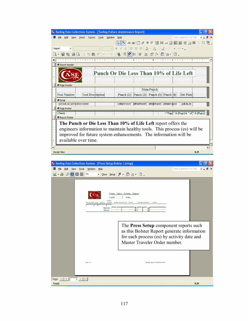
117
The Punch or Die Less Than 10% of Life Left report offers the engineers information to maintain healthy tools. This process (es) will be improved for future system enhancements. The information will be available over time.
The Press Setup component reports such as this Bolster Report generate information for each process (es) by activity date and Master Traveler Order number.

118
The Tool and Die Prep component reports such as this Blade Report generate information for each process (es) by activity date and Master Traveler Order number.
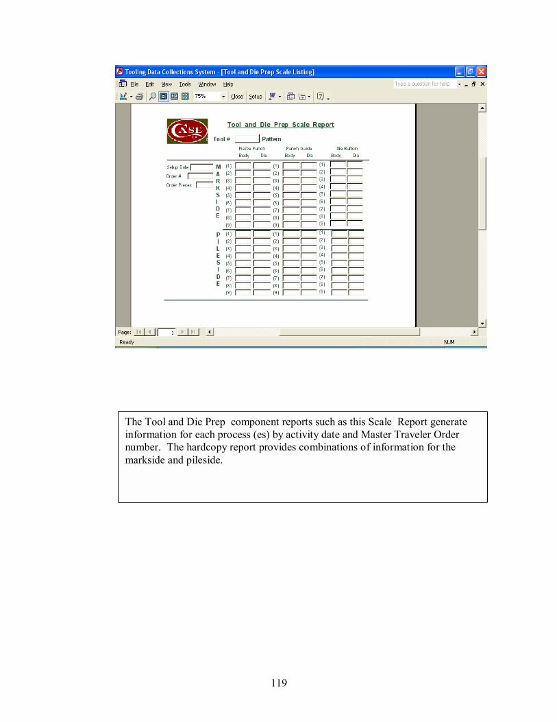
119
The Tool and Die Prep component reports such as this Scale Report generate information for each process (es) by activity date and Master Traveler Order number. The hardcopy report provides combinations of information for the markside and pileside.
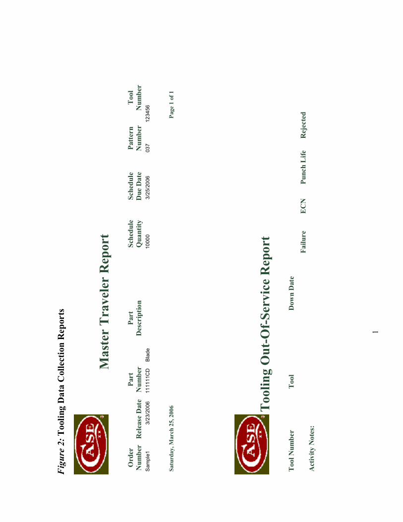
1
Fig
ure
2: T
oolin
g D
ata
Col
lect
ion
Rep
orts
M
aste
r T
rave
ler
Rep
ort
O
rder
Pa
rt
Part
Sc
hedu
le
Sche
dule
Pa
tter
n
Too
l N
umbe
r R
elea
se D
ate
Num
ber
Des
crip
tion
Qua
ntity
D
ue D
ate
Num
ber
Num
ber
Sam
ple1
3/
23/2
006
1111
11C
D
Bla
de
1000
0
3/2
5/20
06
037
12
3456
S
atur
day,
Mar
ch 2
5, 2
006
P
age
1 of
1
Too
ling
Out
-Of-
Serv
ice
Rep
ort
Too
l Num
ber
Too
l D
own
Dat
e
Failu
re
EC
N
Punc
h L
ife
Rej
ecte
d A
ctiv
ity N
otes
:

2
Too
ling
Re-
shar
pen
Qua
ntity
Rep
ort
T
ool
Mai
n Q
ty
Die
Qty
Pi
eces
Sh
arpe
n
Num
ber
Too
l T
rigg
er
Tri
gger
Pr
esse
d
Mai
n
Too
ling
Act
ivity
Mai
nten
ance
T
ool N
umbe
r Pa
rt N
umbe
r Pa
tter
n
EC
N T
ag
Dow
n D
ate
Up
Dat
e M
aint
Dat
e
Cor
rect
ive
Act
ion:
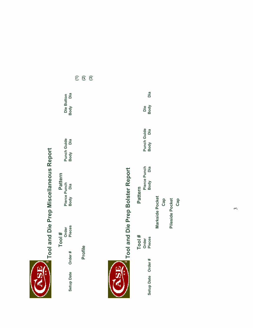
3
Too
l and
Die
Pre
p M
isce
llane
ous
Rep
ort
To
ol #
Pa
ttern
Ord
er
Pier
ce P
unch
Pu
nch
Gui
de
Die
But
ton
Se
tup
Date
O
rder
#
Piec
es
Bod
y
Di
a B
ody
Dia
Bod
y
Di
a
(1)
Pr
ofile
(2
)
(3)
Too
l and
Die
Pre
p B
olst
er R
epor
t
Tool
#
Patte
rn
O
rder
Pi
erce
Pun
ch
Punc
h G
uide
D
ie
Set
up D
ate
Ord
er #
Pi
eces
B
ody
Dia
B
ody
Dia
Bod
y
Di
a
Mar
ksid
e Po
cket
Cap
Pile
side
Poc
ket
C
ap
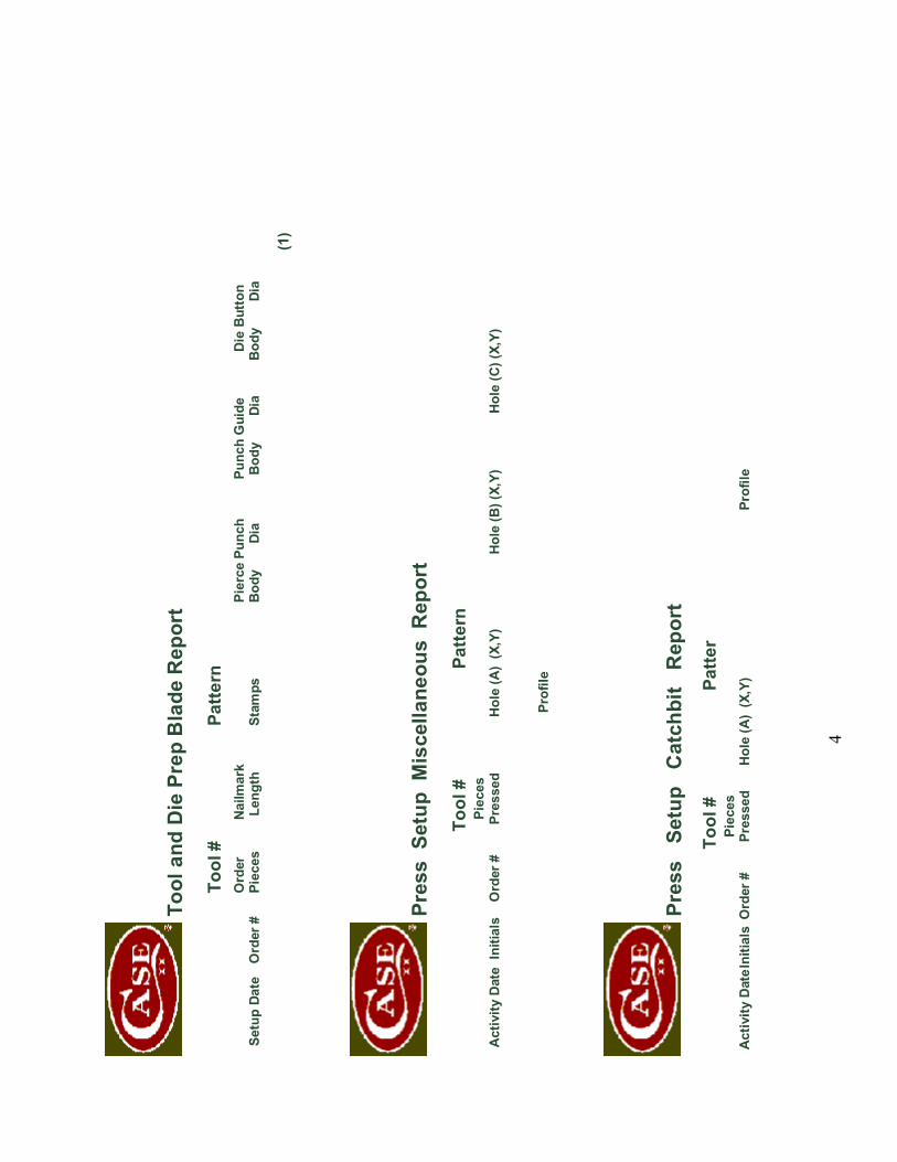
4
Too
l and
Die
Pre
p B
lade
Rep
ort
To
ol #
Pa
ttern
Ord
er
N
ailm
ark
Pi
erce
Pun
ch
Punc
h G
uide
D
ie B
utto
n S
etup
Dat
e O
rder
#
Piec
es
Leng
th
Stam
ps
Bod
y
Di
a B
ody
Dia
Bod
y
Di
a
(1)
Pre
ss S
etup
Mis
cella
neou
s R
epor
t
Tool
#
Patte
rn
Pi
eces
A
ctiv
ity D
ate
Initi
als
Ord
er #
Pr
esse
d H
ole
(A)
(X,Y
) H
ole
(B) (
X,Y)
H
ole
(C) (
X,Y)
Pr
ofile
Pre
ss
Setu
p C
atch
bit
Rep
ort
To
ol #
Pa
tter
Pi
eces
A
ctiv
ity D
ate I
nitia
ls O
rder
#
Pres
sed
Hol
e (A
) (X
,Y)
Prof
ile
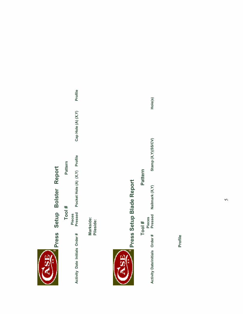
5
Pre
ss
Setu
p B
olst
er
Rep
ort
To
ol #
Pa
ttern
Piec
es
Act
ivity
Dat
e In
itial
s O
rder
#
Pres
sed
Poc
ket H
ole
(A)
(X,Y
) Pr
ofile
C
ap H
ole
(A) (
X,Y)
Pr
ofile
M
arks
ide:
Pile
side
:
Pre
ss S
etup
Bla
de R
epor
t
Tool
#
Patte
rn
Pi
eces
A
ctiv
ity D
ate I
nitia
ls O
rder
#
Pres
sed
Nai
lmar
k (X
,Y)
Stam
p (X
,Y)(S
S/C
V)
Hol
e(s)
Pr
ofile
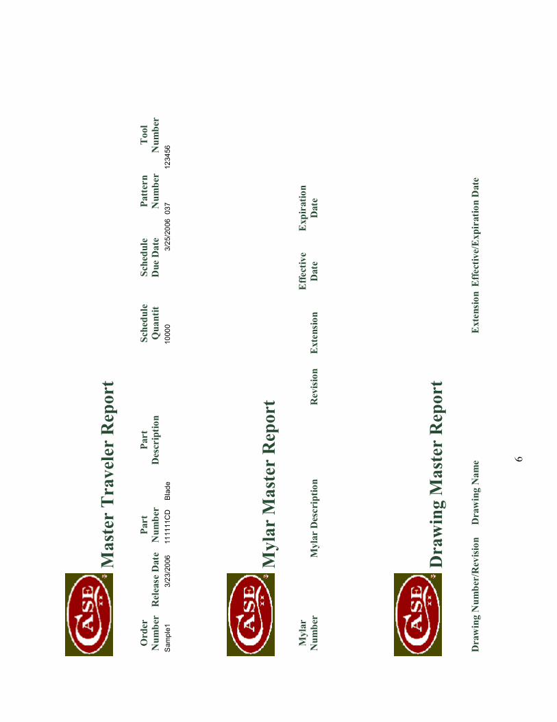
6
Mas
ter
Tra
vele
r R
epor
t
Ord
er
Part
Pa
rt
Sche
dule
Sc
hedu
le
Patt
ern
T
ool
Num
ber
Rel
ease
Dat
e N
umbe
r D
escr
iptio
n Q
uant
it D
ue D
ate
Num
ber
Num
ber
Sam
ple1
3/
23/2
006
1111
11C
D
Bla
de
1000
0 3/
25/2
006
037
1234
56
Myl
ar M
aste
r R
epor
t
Myl
ar
Effe
ctiv
e
Exp
irat
ion
Num
ber
Myl
ar D
escr
iptio
n R
evis
ion
Ext
ensi
on
Dat
e D
ate
Dra
win
g M
aste
r R
epor
t
Dra
win
g N
umbe
r/R
evisi
on
Dra
win
g N
ame
Ext
ensi
on E
ffect
ive/
Exp
irat
ion
Dat
e
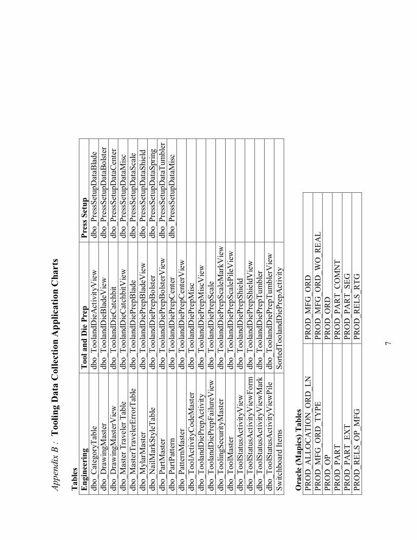
7
Appe
ndix
B :
Too
ling
Dat
a C
olle
ctio
n A
pplic
atio
n C
hart
s T
able
s E
ngin
eeri
ng
Too
l and
Die
Pre
p Pr
ess S
etup
db
o_C
ateg
oryT
able
db
o_To
olan
dDie
Act
ivity
Vie
w
dbo_
Pres
sSet
upD
ataB
lade
db
o_D
raw
ingM
aste
r db
o_To
olan
dDie
Bla
deV
iew
db
o_Pr
essS
etup
Dat
aBol
ster
db
o_D
raw
ingM
aste
rVie
w
dbo_
Tool
andD
ieC
atch
bit
dbo_
Pres
sSet
upD
ataC
ente
r db
o_M
aste
r Tra
vele
r Tab
le
dbo_
Tool
andD
ieC
atch
bitV
iew
db
o_Pr
essS
etup
Dat
aMisc
db
o_M
aste
rTra
vele
rErr
orTa
ble
dbo_
Tool
andD
iePr
epB
lade
db
o_Pr
essS
etup
Dat
aSca
le
dbo_
Myl
arM
aste
r db
o_To
olan
dDie
Prep
Bla
deV
iew
db
o_Pr
essS
etup
Dat
aShi
eld
dbo_
Nai
lMar
kSty
leTa
ble
dbo_
Tool
andD
iePr
epB
olst
er
dbo_
Pres
sSet
upD
ataS
prin
g db
o_Pa
rtMas
ter
dbo_
Tool
andD
iePr
epB
olst
erV
iew
db
o_Pr
essS
etup
Dat
aTum
bler
dbo_
PartP
atte
rn
dbo_
Tool
andD
iePr
epC
ente
r db
o_Pr
essS
etup
Dat
aMisc
db
o_Pa
ttern
Mas
ter
dbo_
Tool
andD
iePr
epC
ente
rVie
w
db
o_To
olA
ctiv
ityC
odeM
aste
r db
o_To
olan
dDie
Prep
Misc
dbo_
Tool
andD
iePr
epA
ctiv
ity
dbo_
Tool
andD
iePr
epM
iscV
iew
dbo_
Tool
andD
iePr
epFa
ilure
Vie
w
dbo_
Tool
andD
iePr
epSc
ale
db
o_To
olin
gSec
urity
Mas
ter
dbo_
Tool
andD
iePr
epSc
aleM
arkV
iew
db
o_To
olM
aste
r db
o_To
olan
dDie
Prep
Scal
ePile
Vie
w
db
o_To
olSt
atus
Act
ivity
Vie
w
dbo_
Tool
andD
iePr
epSh
ield
dbo_
Tool
Stat
usA
ctiv
ityV
iew
Form
db
o_To
olan
dDie
Prep
Shie
ldV
iew
dbo_
Tool
Stat
usA
ctiv
ityV
iew
Mar
k db
o_To
olan
dDie
Prep
Tum
bler
dbo_
Tool
Stat
usA
ctiv
ityV
iew
Pile
db
o_To
olan
dDie
Prep
Tum
bler
Vie
w
Sw
itchb
oard
Item
s So
rtedT
oola
ndD
iePr
epA
ctiv
ity
O
racl
e (M
apic
s) T
able
s PR
OD
_ALL
OC
ATI
ON
_OR
D_L
N
PRO
D_M
FG_O
RD
PR
OD
_MFG
_OR
D_T
YPE
PR
OD
_MFG
_OR
D_W
O_R
EAL
PRO
D_O
P PR
OD
_OR
D
PRO
D_P
AR
T PR
OD
_PA
RT_
CO
MN
T PR
OD
_PA
RT_
EXT
PRO
D_P
AR
T_SE
G
PRO
D_R
ELS_
OP_
MFG
PR
OD
_REL
S_R
TG
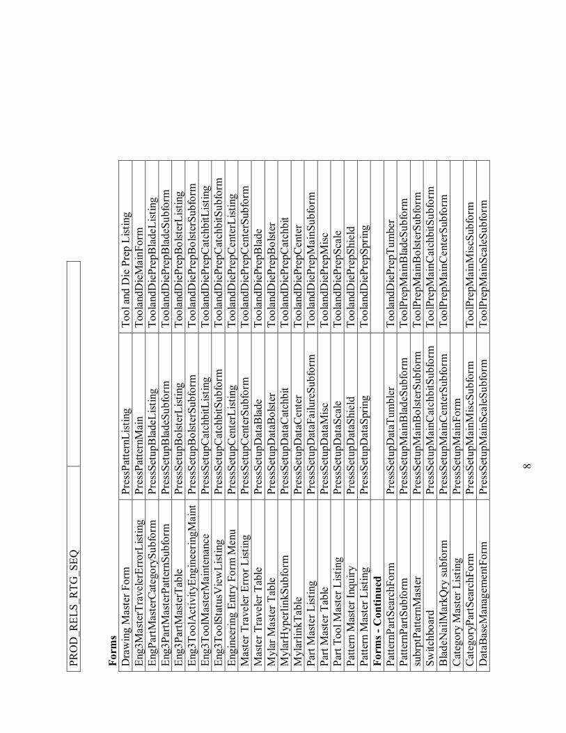
8
PRO
D_R
ELS_
RTG
_SEQ
Form
s D
raw
ing
Mas
ter F
orm
Pr
essP
atte
rnLi
stin
g To
ol a
nd D
ie P
rep
List
ing
Eng3
Mas
terT
rave
lerE
rror
List
ing
Pres
sPat
tern
Mai
n To
olan
dDie
Mai
nFor
m
EngP
artM
aste
rCat
egor
ySub
form
Pr
essS
etup
Bla
deLi
stin
g To
olan
dDie
Prep
Bla
deLi
stin
g En
g3Pa
rtMas
terP
atte
rnSu
bfor
m
Pres
sSet
upB
lade
Subf
orm
To
olan
dDie
Prep
Bla
deSu
bfor
m
Eng3
PartM
aste
rTab
le
Pres
sSet
upB
olst
erLi
stin
g To
olan
dDie
Prep
Bol
ster
List
ing
Eng3
Tool
Act
ivity
Engi
neer
ingM
aint
Pres
sSet
upB
olst
erSu
bfor
m
Tool
andD
iePr
epB
olst
erSu
bfor
m
Eng3
Tool
Mas
terM
aint
enan
ce
Pres
sSet
upC
atch
bitL
istin
g To
olan
dDie
Prep
Cat
chbi
tList
ing
Eng3
Tool
Stat
usV
iew
List
ing
Pres
sSet
upC
atch
bitS
ubfo
rm
Tool
andD
iePr
epC
atch
bitS
ubfo
rm
Engi
neer
ing
Entr
y Fo
rm M
enu
Pres
sSet
upC
ente
rList
ing
Tool
andD
iePr
epC
ente
rList
ing
Mas
ter T
rave
ler E
rror
List
ing
Pres
sSet
upC
ente
rSub
form
To
olan
dDie
Prep
Cen
terS
ubfo
rm
Mas
ter T
rave
ler T
able
Pr
essS
etup
Dat
aBla
de
Tool
andD
iePr
epB
lade
M
ylar
Mas
ter T
able
Pr
essS
etup
Dat
aBol
ster
To
olan
dDie
Prep
Bol
ster
M
ylar
Hyp
erlin
kSub
form
Pr
essS
etup
Dat
aCat
chbi
t To
olan
dDie
Prep
Cat
chbi
t M
ylar
linkT
able
Pr
essS
etup
Dat
aCen
ter
Tool
andD
iePr
epC
ente
r Pa
rt M
aste
r List
ing
Pres
sSet
upD
ataF
ailu
reSu
bfor
m
Tool
andD
iePr
epM
ainS
ubfo
rm
Part
Mas
ter T
able
Pr
essS
etup
Dat
aMisc
To
olan
dDie
Prep
Misc
Pa
rt To
ol M
aste
r List
ing
Pres
sSet
upD
ataS
cale
To
olan
dDie
Prep
Scal
e Pa
ttern
Mas
ter I
nqui
ry
Pres
sSet
upD
ataS
hiel
d To
olan
dDie
Prep
Shie
ld
Patte
rn M
aste
r List
ing
Pres
sSet
upD
ataS
prin
g To
olan
dDie
Prep
Sprin
g Fo
rms -
Con
tinue
d
Pa
ttern
PartS
earc
hFor
m
Pres
sSet
upD
ataT
umbl
er
Tool
andD
iePr
epTu
mbe
r Pa
ttern
PartS
ubfo
rm
Pres
sSet
upM
ainB
lade
Subf
orm
To
olPr
epM
ainB
lade
Subf
orm
su
brpt
Patte
rnM
aste
r Pr
essS
etup
Mai
nBol
ster
Subf
orm
To
olPr
epM
ainB
olst
erSu
bfor
m
Switc
hboa
rd
Pres
sSet
upM
ainC
atch
bitS
ubfo
rm
Tool
Prep
Mai
nCat
chbi
tSub
form
B
lade
Nai
lMar
kQry
sub
form
Pr
essS
etup
Mai
nCen
terS
ubfo
rm
Tool
Prep
Mai
nCen
terS
ubfo
rm
Cat
egor
y M
aste
r List
ing
Pres
sSet
upM
ainF
orm
Cat
egor
yPar
tSea
rchF
orm
Pr
essS
etup
Mai
nMis
cSub
form
To
olPr
epM
ainM
iscS
ubfo
rm
Dat
aBas
eMan
agem
entF
orm
Pr
essS
etup
Mai
nSca
leSu
bfor
m
Tool
Prep
Mai
nSca
leSu
bfor
m
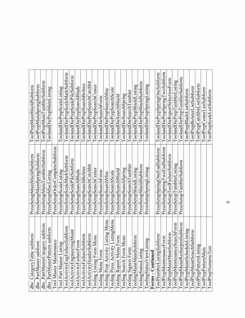
9
dbo_
Cat
egor
yTab
le su
bfor
m
Pres
sSet
upM
ainS
hiel
dSub
form
To
olPr
epM
ainS
hiel
dSub
form
db
o_Pa
rtMas
ter s
ubfo
rm
Pres
sSet
upM
ainS
prin
gSub
form
To
olPr
epM
ainS
prin
gSub
form
db
o_Pa
rtMas
terC
ateg
ory
subf
orm
Pr
essS
etup
Mai
nTum
bler
Subf
orm
To
olPr
epM
ainT
umbl
erSu
bfor
m
dbo_
PartM
aste
rPat
tern
subf
orm
Pr
essS
etup
Misc
List
ing
Tool
andD
iePr
epM
ainL
istin
g To
ol M
aste
r Mai
nten
ance
Pr
essS
etup
Ord
erCo
mpl
eteS
ubfo
rm
Tool
Par
t Mas
ter L
istin
g Pr
essS
etup
Scal
eList
ing
Tool
andD
iePr
epSc
aleL
istin
g To
olA
ctiv
ityEn
gFai
lure
Subf
orm
Pr
essS
etup
Scal
eMar
kSub
form
To
olan
dDie
Prep
Scal
eMar
kSub
form
To
olA
ctiv
ityEn
gine
erin
gMai
nt
Pres
sSet
upSc
aleP
ileSu
bfor
m
Tool
andD
iePr
epSc
aleP
ileSu
bfor
m
Tool
Act
ivity
Failu
reFo
rm
Pres
sSet
upSe
arch
Bla
de
Tool
andD
iePr
epSe
arch
Bla
de
Tool
Act
ivity
Failu
reSu
bfor
m
Pres
sSet
upSe
arch
Bol
ster
To
olan
dDie
Prep
Sear
chB
olst
er
Tool
Act
ivity
Hea
derS
ubfo
rm
Pres
sSet
upSe
arch
Cat
chbi
t To
olan
dDie
Prep
Sear
chC
atch
bit
Tool
ing
List
ing
Form
Men
u Pr
essS
etup
Sear
chC
ente
r To
olan
dDie
Prep
Sear
chC
ente
r To
olin
g M
enu
Form
Pr
essS
etup
Sear
chFo
rm
Tool
andD
ieSe
arch
Form
To
olin
g Pr
ep A
ctiv
ity L
istin
g M
enu
Pres
sSet
upSe
arch
Misc
To
olan
dDie
Prep
Sear
chM
isc
Tool
ing
Pres
s A
ctiv
ity L
istin
gMen
u Pr
essS
etup
Sear
chSc
ale
Tool
andD
iePr
epSe
arch
Scal
e To
olin
g R
epor
t Men
u Fo
rm
Pres
sSet
upSe
arch
Shie
ld
Tool
andD
ieSe
arch
Shie
ld
Tool
ing
Sear
ch F
orm
Men
u Pr
essS
etup
Sear
chSp
ring
Tool
andD
ieSe
arch
Sprin
g To
olin
g Si
gnon
For
m
Pres
sSet
upSe
arch
Tum
bler
To
olan
dDie
Sear
chTu
mbl
er
Tool
ingM
aint
Mai
nSub
form
Pr
essS
etup
Shie
ldLi
stin
g To
olan
dDie
Prep
Shie
ldLi
stin
g To
olin
gSta
tusL
istin
g Pr
essS
etup
Shie
ldSu
bfor
m
Tool
andD
iePr
epSh
ield
Subf
orm
To
olin
gSta
tusV
iew
List
ing
Pres
sSet
upSp
ringL
istin
g To
olan
dDie
Prep
Sprin
gList
ing
Form
s - C
ontin
ued
Tool
Num
berL
istin
gSub
form
Pr
essS
etup
Sprin
gOne
EndS
ubfo
rm
Tool
andD
iePr
epSp
ringO
neSu
bfor
m
Tool
Prep
Mai
nten
ance
Form
Pr
essS
etup
Sprin
gTw
oEnd
Subf
orm
To
olan
dDie
Prep
Sprin
gTw
oSub
form
Tool
Prep
Mai
ntM
ainS
ubfo
rm
Pres
sSet
upTo
olFa
ilure
Subf
orm
To
olan
dDie
Rep
ortS
elec
tionF
orm
To
olPr
epM
aint
enan
ceSe
arch
Form
Pr
essS
etup
Tum
bler
List
ing
Tool
andD
iePr
epTu
mbl
erLi
stin
g To
olPr
epM
aint
Res
harp
enSu
bfor
m
Pres
sSet
upTu
mbl
erSu
bfor
m
Tool
andD
iePr
epTu
mbl
erSu
bfor
m
Tool
Prep
Mai
ntSc
hedu
leLi
stin
g
Tool
Prep
Bla
deLi
stSu
bfor
m
Tool
Prep
Mai
ntSe
arch
Subf
orm
Tool
Prep
Bol
ster
List
Subf
orm
To
olPr
epPa
ttern
List
ing
To
olPr
epC
atch
bitL
istSu
bfor
m
Tool
Prep
Patte
rnM
ain
To
olPr
epC
ente
rList
Subf
orm
To
olPr
epN
umer
icTe
st
To
olPr
epSc
aleL
istSu
bfor
m
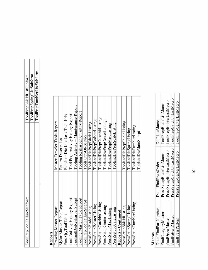
10
Tool
Prep
Tool
Failu
reSu
bfor
m
To
olPr
epSh
ield
List
Subf
orm
To
olPr
epSp
ringL
istSu
bfor
m
Tool
Prep
Tum
bler
List
Subf
orm
R
epor
ts
Dra
win
g M
aste
r Rep
ort
Mas
ter T
rave
ler T
able
Rep
ort
Myl
ar M
aste
r Tab
le R
epor
t Pa
ttern
Des
crip
tion
Pres
sQty
Tool
Tabl
e Pu
nch
or D
ie L
ife L
ess T
han
10%
To
ol A
ctiv
ity H
istor
y R
epor
t To
ol P
rep
Act
ivity
Hist
ory
Rep
ort
Tool
andD
ieR
esha
rpen
Subr
pt
Tool
ing
Act
ivity
� M
aint
enan
ce R
epor
t To
olin
g M
aste
r Tab
le R
epor
t To
olin
g R
esha
rpen
Qua
ntity
Rep
ort
Tool
Prep
Tool
Failu
reSu
brpt
To
ols O
ut-O
f-Ser
vice
Pr
essS
etup
Bla
deLi
stin
g To
olan
dDie
Prep
Bla
deLi
stin
g Pr
essS
etup
Bol
ster
List
ing
Tool
andD
iePr
epB
olst
erLi
stin
g Pr
essS
etup
Cat
chbi
tList
ing
Tool
andD
iePr
epC
atch
bitL
istin
g Pr
essS
etup
Cen
terL
istin
g To
olan
dDie
Prep
Cen
terL
istin
g Pr
essS
etup
Misc
List
ing
Tool
andD
iePr
epM
iscLi
stin
g Pr
essS
etup
Scal
eList
ing
Tool
andD
iePr
epSc
aleL
istin
g R
epor
ts -
Con
tinue
d
Pres
sSet
upSh
ield
List
ing
Tool
andD
iePr
epSh
ield
List
ing
Pres
sSet
upSp
ringL
istin
g To
olan
dDie
Sprin
gList
ing
Pres
sSet
upTu
mbl
erLi
stin
g To
olan
dDie
Tum
bler
List
ing
To
olan
dDie
Mai
nSub
rpt
Mac
ros
Det
ailF
indP
artN
umbe
r D
etai
lFin
dPre
ssO
rder
D
iePl
ateM
acro
Fi
ndC
ateg
oryM
aste
r Pr
essS
etup
Bla
deLi
stM
acro
To
olPr
epB
lade
List
Mac
ro
Find
Ord
erM
aste
r Pr
essS
etup
Bol
ster
List
Mac
ro
Tool
Prep
Bol
ster
List
Mac
ro
Find
Patte
rnM
aste
r Pr
essS
etup
Cat
chbi
tList
Mac
ro
Tool
Prep
Cat
chbi
tList
Mac
ro
Find
Pres
sPat
tern
Pr
essS
etup
Cen
terL
istM
acro
To
olPr
epC
ente
rList
Mac
ro
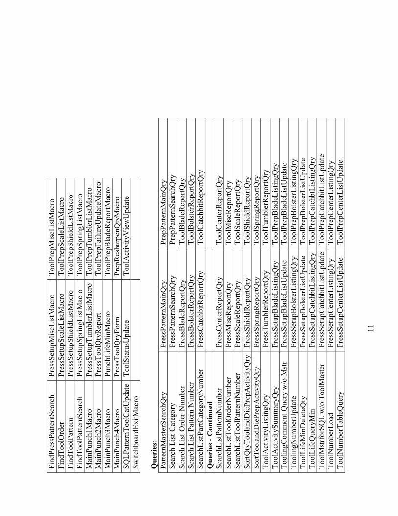
11
Find
Pres
sPat
tern
Sear
ch
Pres
sSet
upM
iscLi
stM
acro
To
olPr
epM
iscLi
stM
acro
Fi
ndTo
olO
rder
Pr
essS
etup
Scal
eList
Mac
ro
Tool
Prep
Scal
eList
Mac
ro
Find
Tool
Patte
rn
Pres
sSet
upSh
ield
List
Mac
ro
Tool
Prep
Shie
ldLi
stM
acro
Fi
ndTo
olPa
ttern
Sear
ch
Pres
sSet
upSp
ringL
istM
acro
To
olPr
epSp
ringL
istM
acro
M
ainP
unch
1Mac
ro
Pres
sSet
upTu
mbl
erLi
stM
acro
Tool
Prep
Tum
bler
List
Mac
ro
Mai
nPun
ch2M
acro
Pr
essT
oolQ
tyR
epor
t To
olPr
epFa
ilure
Upd
ateM
acro
Mai
nPun
ch3M
acro
Pu
nchL
ifeM
inM
acro
To
olPr
epB
lade
Rep
ortM
acro
M
ainP
unch
4Mac
ro
Pres
sToo
lQry
Form
Pr
epR
esha
rpen
Qty
Mac
ro
SQLP
atte
rnTo
olC
atU
pdat
e To
olSt
atus
Upd
ate
Tool
Act
ivity
Vie
wU
pdat
e Sw
itchb
oard
ExitM
acro
Q
ueri
es:
Patte
rnM
aste
rSea
rchQ
ry
Pres
sPat
tern
Mai
nQry
Pr
epPa
ttern
Mai
nQry
Se
arch
List
Cat
egor
y Pr
essP
atte
rnSe
arch
Qry
Pr
epPa
ttern
Sear
chQ
ry
Sear
ch L
ist O
rder
Num
ber
Pres
sBla
deR
epor
tQry
To
olB
lade
Rep
ortQ
ry
Sear
ch L
ist P
atte
rn N
umbe
r Pr
essB
olst
erR
epor
tQry
To
olB
olst
erR
epor
tQry
Se
arch
List
PartC
ateg
oryN
umbe
r Pr
essC
atch
bitR
epor
tQry
To
olC
atch
bitR
epor
tQry
Q
ueri
es -
Con
tinue
d
Se
arch
List
Patte
rnN
umbe
r Pr
essC
ente
rRep
ortQ
ry
Tool
Cen
terR
epor
tQry
Se
arch
List
Tool
Ord
erN
umbe
r Pr
essM
iscR
epor
tQry
To
olM
iscR
epor
tQry
Se
arch
List
Tool
Patte
rnN
umbe
r Pr
essS
cale
Rep
ortQ
ry
Tool
Scal
eRep
ortQ
ry
SortQ
tyTo
olan
dDie
Prep
Act
ivity
Qry
Pres
sShi
eldR
epor
tQry
To
olSh
ield
Rep
ortQ
ry
SortT
oola
ndD
iePr
epA
ctiv
ityQ
ry
Pres
sSpr
ingR
epor
tQry
To
olSp
ringR
epor
tQry
To
olA
ctiv
ityLi
stin
gQry
Pr
essT
umbl
erR
epor
tQry
To
olTu
mbl
erR
epor
tQry
To
olA
ctiv
itySu
mm
aryQ
ry
Pres
sSet
upB
lade
List
ingQ
ry
Tool
Prep
Bla
deLi
stin
gQry
To
olin
gCom
men
t Que
ry w
/o M
str
Pres
sSet
upB
lade
List
Upd
ate
Tool
Prep
Bla
deLi
stU
pdat
e To
olin
gNum
berU
pdat
e Pr
essS
etup
Bol
ster
List
ingQ
ry
Tool
Prep
Bol
ster
List
ingQ
ry
Tool
Life
Min
Del
eteQ
ty
Pres
sSet
upB
olst
erLi
stU
pdat
e To
olPr
epB
olst
erLi
stU
pdat
e To
olLi
feQ
uery
Min
Pr
essS
etup
Cat
chbi
tList
ingQ
ry
Tool
Prep
Cat
chbt
List
ingQ
ry
Tool
Mst
rfor
SQL
w/o
Too
lMas
ter
Pres
sSet
upC
atch
bitL
istU
pdat
eTo
olPr
epC
atch
bitL
istU
pdat
e To
olN
umbe
rLoa
d Pr
essS
etup
Cen
terL
istin
gQry
To
olPr
epC
ente
rList
ingQ
ry
Tool
Num
berT
able
Que
ry
Pres
sSet
upC
ente
rList
Upd
ate
Tool
Prep
Cen
terL
istU
pdat
e
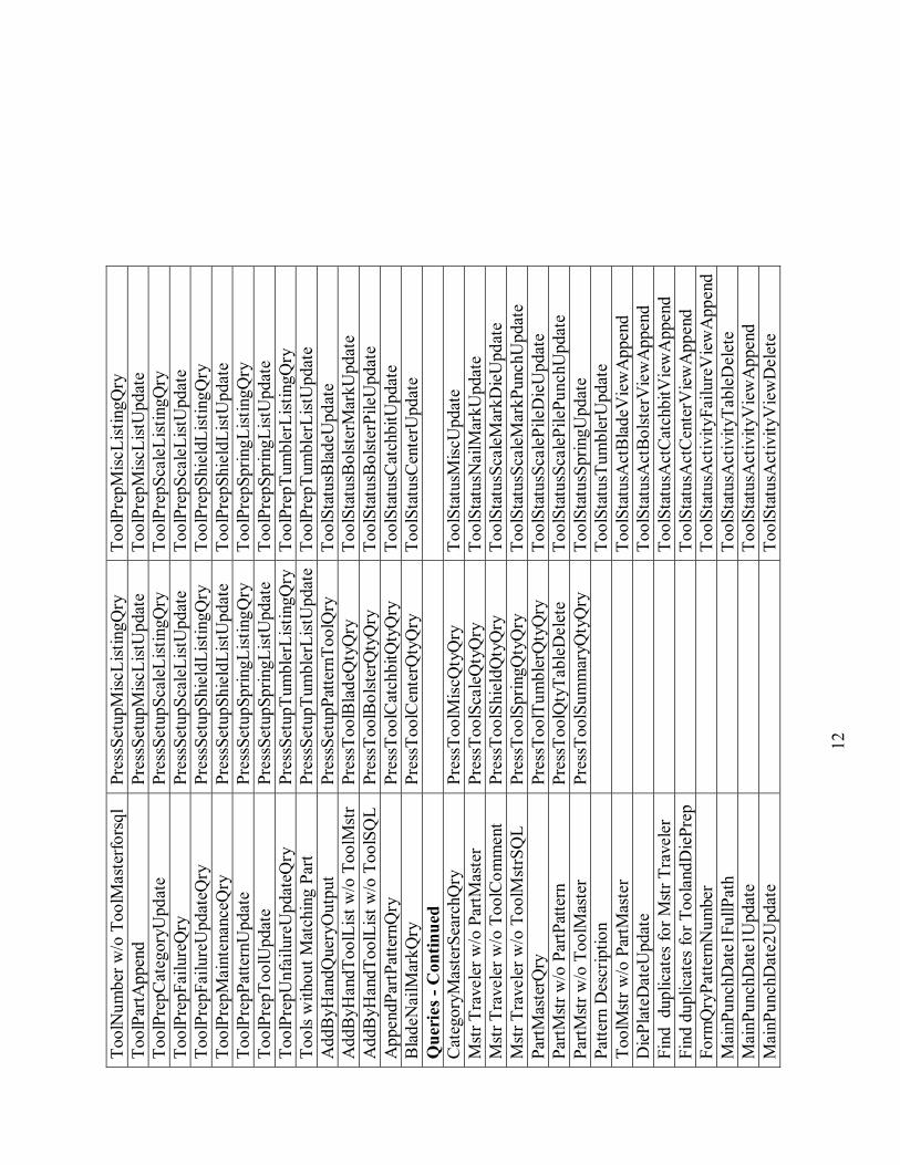
12
Tool
Num
ber w
/o T
oolM
aste
rfors
ql
Pres
sSet
upM
iscLi
stin
gQry
To
olPr
epM
iscLi
stin
gQry
To
olPa
rtApp
end
Pres
sSet
upM
iscLi
stU
pdat
e To
olPr
epM
iscLi
stU
pdat
e To
olPr
epC
ateg
oryU
pdat
e Pr
essS
etup
Scal
eList
ingQ
ry
Tool
Prep
Scal
eList
ingQ
ry
Tool
Prep
Failu
reQ
ry
Pres
sSet
upSc
aleL
istU
pdat
e To
olPr
epSc
aleL
istU
pdat
e To
olPr
epFa
ilure
Upd
ateQ
ry
Pres
sSet
upSh
ield
List
ingQ
ry
Tool
Prep
Shie
ldLi
stin
gQry
To
olPr
epM
aint
enan
ceQ
ry
Pres
sSet
upSh
ield
List
Upd
ate
Tool
Prep
Shie
ldLi
stU
pdat
e To
olPr
epPa
ttern
Upd
ate
Pres
sSet
upSp
ringL
istin
gQry
To
olPr
epSp
ringL
istin
gQry
To
olPr
epTo
olU
pdat
e Pr
essS
etup
Sprin
gList
Upd
ate
Tool
Prep
Sprin
gList
Upd
ate
Tool
Prep
Unf
ailu
reU
pdat
eQry
Pr
essS
etup
Tum
bler
List
ingQ
ryTo
olPr
epTu
mbl
erLi
stin
gQry
To
ols w
ithou
t Mat
chin
g Pa
rt Pr
essS
etup
Tum
bler
List
Upd
ate
Tool
Prep
Tum
bler
List
Upd
ate
Add
ByH
andQ
uery
Out
put
Pres
sSet
upPa
ttern
Tool
Qry
To
olSt
atus
Bla
deU
pdat
e A
ddB
yHan
dToo
lList
w/o
Too
lMst
r Pr
essT
oolB
lade
Qty
Qry
To
olSt
atus
Bol
ster
Mar
kUpd
ate
Add
ByH
andT
oolL
ist w
/o T
oolS
QL
Pres
sToo
lBol
ster
Qty
Qry
To
olSt
atus
Bol
ster
Pile
Upd
ate
App
endP
artP
atte
rnQ
ry
Pres
sToo
lCat
chbi
tQty
Qry
To
olSt
atus
Cat
chbi
tUpd
ate
Bla
deN
ailM
arkQ
ry
Pres
sToo
lCen
terQ
tyQ
ry
Tool
Stat
usC
ente
rUpd
ate
Que
ries
- C
ontin
ued
Cat
egor
yMas
terS
earc
hQry
Pr
essT
oolM
iscQ
tyQ
ry
Tool
Stat
usM
iscU
pdat
e M
str T
rave
ler w
/o P
artM
aste
r Pr
essT
oolS
cale
Qty
Qry
To
olSt
atus
Nai
lMar
kUpd
ate
Mst
r Tra
vele
r w/o
Too
lCom
men
t Pr
essT
oolS
hiel
dQty
Qry
To
olSt
atus
Scal
eMar
kDie
Upd
ate
Mst
r Tra
vele
r w/o
Too
lMst
rSQ
L Pr
essT
oolS
prin
gQty
Qry
To
olSt
atus
Scal
eMar
kPun
chU
pdat
e Pa
rtMas
terQ
ry
Pres
sToo
lTum
bler
Qty
Qry
To
olSt
atus
Scal
ePile
Die
Upd
ate
PartM
str w
/o P
artP
atte
rn
Pres
sToo
lQty
Tabl
eDel
ete
Tool
Stat
usSc
aleP
ilePu
nchU
pdat
e Pa
rtMst
r w/o
Too
lMas
ter
Pres
sToo
lSum
mar
yQty
Qry
To
olSt
atus
Sprin
gUpd
ate
Patte
rn D
escr
iptio
n
Tool
Stat
usTu
mbl
erU
pdat
e To
olM
str w
/o P
artM
aste
r
Tool
Stat
usA
ctB
lade
Vie
wA
ppen
d D
iePl
ateD
ateU
pdat
e
Tool
Stat
usA
ctB
olst
erV
iew
App
end
Find
dup
licat
es fo
r Mst
r Tra
vele
r
Tool
Stat
usA
ctC
atch
bitV
iew
App
end
Find
dup
licat
es fo
r Too
land
Die
Prep
Tool
Stat
usA
ctC
ente
rVie
wA
ppen
d Fo
rmQ
ryPa
ttern
Num
ber
To
olSt
atus
Act
ivity
Failu
reV
iew
App
end
Mai
nPun
chD
ate1
FullP
ath
To
olSt
atus
Act
ivity
Tabl
eDel
ete
Mai
nPun
chD
ate1
Upd
ate
To
olSt
atus
Act
ivity
Vie
wA
ppen
d M
ainP
unch
Dat
e2U
pdat
e
Tool
Stat
usA
ctiv
ityV
iew
Del
ete
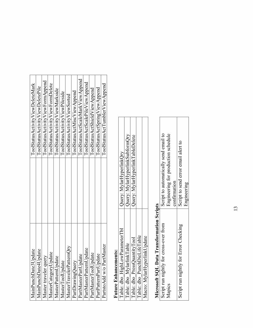
13
Mai
nPun
chD
ate3
Upd
ate
To
olSt
atus
Act
ivity
Vie
wD
elet
eMar
k M
ainP
unch
Dat
e4U
pdat
e
Tool
Stat
usA
ctiv
ityV
iew
Del
eteP
ile
Mas
ter t
rave
ler q
uery
Tool
Stat
usA
ctiv
ityV
iew
Form
App
end
Mas
terC
ateg
oryU
pdat
e
Tool
Stat
usA
ctiv
ityV
iew
Form
Del
ete
Mas
terP
atte
rnU
pdat
e
Tool
Stat
usA
ctiv
ityV
iew
Mar
ksid
e M
aste
rToo
lUpd
ate
To
olSt
atus
Act
ivity
Vie
wPi
lesi
de
Mas
terT
rave
lerP
atte
rnQ
ry
To
olSt
atus
Act
ivity
Vie
wSo
rted
PartD
raw
ingQ
uery
Tool
Stat
usA
ctM
iscV
iew
App
end
PartM
aste
rPar
tUpd
ate
To
olSt
atus
Act
Scal
eMar
kVie
wA
ppen
d Pa
rtMas
terP
atte
rnU
pdat
e
Tool
Stat
usA
ctSc
aleP
ileV
iew
App
end
PartM
aste
rToo
lUpd
ate
To
olSt
atus
Act
Shie
ldV
iew
App
end
PartP
atte
rnPa
rtUpd
ate
To
olSt
atus
Act
Sprin
gVie
wA
ppen
d Pa
rtsto
Add
w/o
Par
tMas
ter
To
olSt
atus
Act
Tum
bler
Vie
wA
ppen
d Fu
ture
Enh
ance
men
ts:
Tabl
e: d
bo_H
ighL
owPa
ram
eter
Tbl
Que
ry: M
ylar
Hyp
erlin
kQry
Ta
ble:
dbo
_Myl
arlin
kTab
le
Que
ry: M
ylar
Hyp
erlin
kSub
form
Qry
Ta
ble:
dbo
_Pre
ssQ
uant
ityTo
ol
Que
ry: M
ylar
Hyp
erlin
kTab
leD
elet
e Ta
ble:
dbo
_Pun
chD
ieLi
feTa
ble
M
acro
: Myl
arH
yper
linkU
pdat
e
Mic
roso
ft S
QL
Dat
a T
rans
form
atio
n Sc
ript
s Sc
ript r
un n
ight
ly fo
r cro
ss-o
ver f
rom
M
apic
s Sc
ript t
o au
tom
atic
ally
sen
d em
ail t
o En
gine
erin
g fo
r pro
duct
ion
sche
dule
co
nfirm
atio
n Sc
ript r
un n
ight
ly fo
r Err
or C
heck
ing
Scrip
t to
send
err
or e
mai
l ale
rt to
En
gine
erin
g