to: planholders
TRANSCRIPT

DIVISION 00 - PROCUREMENT AND CONTRACTING REQUIREMENTS SECTION 00 91 11.03 – ADDENDUM NUMBER THREE
May 3, 2016
TO: PLANHOLDERS
SUBJECT: PIER 4 PHASE 2 RECONFIGURATION
PROJECT NO. 091251 CONTRACT NO. 070136
ADDENDUM NUMBER THREE
This addendum is issued to amend the following:
SPECIFICATIONS
A. 00 41 00 BID FORM (VOLUME 1 OF 3)
1. DELETE and REPLACE the issued Section 00 41 00 – Bid Form with the attached revised Section 00 41 00 – Bid Form reflecting revision to Bid Items 10 and 11. (See Attachment A to this Addendum No. 3)
B. 01 20 00 PRICE AND PAYMENT PROCEDURES (VOLUME 1 OF 3)
1. REVISE paragraph 1.06.F.2 to read as follows:
2. Measurement: This item will be measured by the horizontal linear foot of the wall system removed as illustrated on the drawings. and as discussed in specification section 02 41 00, paragraph 3.03.A.
C. 02 41 00 - DEMOLITION (VOLUME 1 OF 3)
1. REVISE paragraph 3.03.A to read as follows:
A. … the project. Measurement for payment of wall system removal shall be based on the horizontal length of wall system removed. The wall system shall be defined as shown on Sheet 2 of the reference drawings titled, “Pier IV Bulkhead Construction”, EP-1318-4, dated February 1966 identified in Section 00 31 00 – Available Project Information. Each horizontal lineal foot of the wall system includes the entire bulkhead section, including all piles, planks, braces, tie-back cables, and connection hardware. Estimation of bid quantities and costs associated with removal and disposal of the wall, and impacts to construction schedule and sequencing, shall be made by the Contractor based on information contained on the Contract Drawings and the record reference drawings indicated herein
Project No. 091251 00 91 11.03 - 1 Contract No. 070136

DIVISION 00 - PROCUREMENT AND CONTRACTING REQUIREMENTS SECTION 00 91 11.03 – ADDENDUM NUMBER THREE
D. 31 66 13 – STONE COLUMNS (VOLUME 1 OF 3)
1. REVISE paragraph 2.01.B.3 as follows: 3. The gradation of stone, measured according to ASTM D 422, shall conform to the following
AASHTO No. 57 grading requirements:
Sieve Size Percentage Passing 1.5 inch square 100 1 inch square 95 to 100 1/2 inch square 25 to 60 U.S. No.4 sieve 0 to 10 U.S. No.8 sieve 0 to 5 U.S. No. 200 sieve 0
E. 26 22 13.01 – DRY TYPE TRANSFORMER (VOLUME 2 OF 3)
1. DELETE and REPLACE the issued section with the attached Section 26 22 13.01 - Dry Type Transformer. (Attachment B to this Addendum No. 3)
F. 03 30 00.01 – CAST-IN-PLACE CONCRETE (VOLUME 2 OF 3)
1. ADD to paragraph 2.07.A.1 the following manufacturer and product:
f. W.R. Meadows; Sealtight Perminator HP 15 mil.
2. REVISE paragraph 2.08.b to read as follows:
3. …concrete slabs scheduled as “CS” (Clear Sealer). “SC” (Sealed Concrete). This applies only…
G. 05 50 00.01 – METAL FABRICATIONS (VOLUME 2 OF 3)
1. REVISE paragraph 2.08.B to read as follows:
B. Provide Interior Exterior Vertical Ladders…
2. REVISE paragraph 2.08.B.1 to read as follows:
1. Provide Model #502 #503A extruded…
H. 05 51 00.01 – METAL STAIRS
1. REVISE paragraph 2.06.D.2.b to read as follows:
b. Finish: Powder Coat. Provide manufacturer standard colors for selection by Engineer. Color as indicated on drawings. Provide color sample for approval by Engineer.
Project No. 091251 00 91 11.03 - 2 Contract No. 070136

DIVISION 00 - PROCUREMENT AND CONTRACTING REQUIREMENTS SECTION 00 91 11.03 – ADDENDUM NUMBER THREE
I. 07 13 26.01 - SELF-ADHERING SHEET WATERPROOFING
1. ADD to paragraph 2.02.A.1 the following manufacturer and product:
c. W.R. Meadows; MEL-ROL Rolled, Self-Adhering Waterproofing Membrane.
2. ADD to paragraph 2.03.A.1 the following manufacturer and product:
c. W.R. Meadows; PRECON Blindside Waterproofing / Underslab Membrane.
J. 09 51 13.01 – ACOUSTICAL PANEL CEILINGS
1. ADD to paragraph 2.02.A. the following manufacturer and product:
4. Rockfon; Sonar 24”x48” with Square Tegular Narrow suspension system. DRAWINGS
A. DRAWING G7.1 – EXISTING CONDITIONS PLAN (SHEET 11)
1. REVISE Timber Bulkhead Notes as indicated on the revised drawing. (See Attachment C to this Addendum No. 3)
B. DRAWING D1.2 – UTILITY AND SITE DEMOLITION PLAN – SHEET 2 (SHEET 21)
1. REVISE Timber Bulkhead Notes and Key Notes as indicated on the revised drawing. (See Attachment D to this Addendum No. 3)
C. DRAWING C3.1 – SLOPE PROTECTION PLAN (SHEET 52)
1. ADD light rock rip rap and filter blanket in specified area benched for pile and pile cap installation, 2,300 square feet. (See Attachment E to this Addendum No. 3)
D. DRAWING C3.3 – SLOPE PROTECTION SECTIONS – SHEET 2 (SHEET 54)
1. ADD light rock rip rap and filter blanket waterside of bulkhead as denoted. (See Attachment F to this Addendum No. 3)
E. DRAWING E3.2 – SITE ELECTRICAL PLAN (SHEET 128)
1. REVISE General Note 2 to read as follows:
2. SEE SHEET E8.3 FOR WIFIC SERIES FOR PROVIDING COMM CABLES IN THESE EXISTING DUCTBANKS.
F. DRAWING S4.2 – PILE AND PILE CAP PLAN – SHEET 2 (SHEET 180)
1. REPLACE entire sheet with attached sheet to include existing slope contours. (See Attachment G to this Addendum No. 3)
Project No. 091251 00 91 11.03 - 3 Contract No. 070136

DIVISION 00 - PROCUREMENT AND CONTRACTING REQUIREMENTS SECTION 00 91 11.03 – ADDENDUM NUMBER THREE
G. DRAWING S27.45 – DECK PANEL DETAILS – SHEET 45 (SHEET 340)
1. REVISE Detail A Typical Crane Beam Panel Type “L” Section P2A and Detail B Typical Type “R” Crane Beam Panel Elevation as denoted. (See Attachment H to this Addendum No. 3)
H. DRAWING S27.48 – DECK PANEL DETAILS – SHEET 48 (SHEET 343)
1. REVISE Detail A Crane Beam Pan Type ‘R’ Section P8A and Detail B Deck Panel Elevation as denoted. (See Attachment I to this Addendum No. 3)
I. DRAWING S36.1 CRANE STOP DETAILS (SHEET 369)
1. REVISE height of crane stop, as denoted in Detail 1 Elevation –Crane Stops Landside and Waterside; anchoring, as denoted in Detail 3 Detail – Crane Stop Base Plate Anchoring –Front Post; and welds, as denoted in Detail A Section – Crane Stop Base Plate – Front Post. (See Attachment J to this Addendum No. 3)
J. DRAWING A7.00 - MARINE BUILDING VERTICAL CIRCULATION (SHEET 410) – DETAIL 2 VERTICAL CIRCULATION – STAIR
1. REVISE drawing note to read as follows:
PIPE RAIL CONTINUED FROM HANDRAIL TO WALL WITH MINIMUM 3 VERTICAL SUPPORTS TO FLOOR TO PREVENT ACCESS UNDER STAIR, HPC-3
K. DRAWING A8.01 – MARINE BUILDING INTERIOR ELEVATIONS (SHEET 412) – DETAIL 2 100 BREAK ROOM N
1. REVISE the abbreviation TPD (x4 locations) to read as follows:
TPD PTD
L. DRAWING A8.02 – MARINE BUILDING INTERIOR ELEVATIONS (SHEET 413) – DETAIL 11 105 KITCHEN N
1. REVISE the abbreviation TPD (x4 locations) to read as follows:
TPD PTD
M. DRAWING A50.02 – MARINE BUILDING VERTICAL CIRCULATION DETAILS (SHEET 432) – DETAIL 4 ELEVATOR – PIT LADDER
1. REVISE the width of the pit ladder dimension from 1’-2” from outside of rungs to 1’-4” form insides of rungs.
2. REVISE the offset of the ladder 3.5” max from the outside face of ladder to the face of wall to 4.5” max from centerline of rung to face of wall.
N. DRAWING M1.02 – MARINE BUILDING SCHEDULES (SHEET 471) – EXHAUST FAN SCHEDULE 1. ADD note 3 from NOTES FOR EXHAUST FAN SCHEDULE to NOTES column for UNIT NO.
EF-1 and EF-2.
Project No. 091251 00 91 11.03 - 4 Contract No. 070136

DIVISION 00 - PROCUREMENT AND CONTRACTING REQUIREMENTS SECTION 00 91 11.03 – ADDENDUM NUMBER THREE
O. DRAWING M1.02 – MARINE BUILDING SCHEDULES (SHEET 471) – RELIEF ROOF HOOD SCHEDULE
1. ADD note 1 from NOTES FOR RELIEF ROOF SCHEDULE to REMARKS column for UNIT NO. RH-1.
P. DRAWING E1.00 – MARINE BUILDING ELECTRICAL FIXTURE SCHEDULE AND MECHANICAL CONNECTION SCHEDULE (SHEET 488)
1. REVISE light fixture RL3 Description as follows:
KENALL 26L40K-DV-SCC-FW-CSS-8 MRDL6ICL-26340K-DV-SCC-FW-CSS-8
2. REVISE light fixture RL3E Description as follows:
KENALL 26L40K-DV-SCC-FW-CSS-8 EL MRDL6ICL-26340K-DV-SCC-FW-CSS-8-EL
3. REVISE light fixture RL3E Mounting and Remarks as follows:
6” ROUND, LENSED, RECESSED LED DOWNLIGHT FIXTURE. IC RATED. PROVIDE WITH INTEERGRAL EMERGENCY BATTERY – 500LU MIN. 6” ROUND, LENSED, WET LOCATION, IC RATED, RECESSED DOWNLIGHT LED FIXTURE. PROVIDE FIXTURE WITH REMOTE EMERGENCY DRIVER WITH MINIMUM OF 500 OUTPUT LUMEN.
4. REVISE light fixture PL2E Mounting and Remarks to include the following:
MOUNT WITH BOTTOM OF FIXTURE AT 9’-6” AFF.
5. REVISE light fixture WL4E Mounting and Remarks to include the following:
MOUNT WITH TOP OF FIXTURE AT 7’-8” AFF, APPROXIMATELY EVEN WITH THE TOP OF THE BEAM FRAMING.
K. DRAWING E2.01 – MARINE BUILDING LEVEL 1 AND LEVEL 2 LIGHTING PLAN (SHEET 489) – DETAIL 1 LEVEL 1 LIGHTING PLAN 1. ADD low voltage Switch LV2 location on east wall side adjacent to the Kitchen 105 corner wall
by gridlines 3/C.3.
L. DRAWING E2.01 – MARINE BUILDING LEVEL 1 AND LEVEL 2 LIGHTING PLAN (SHEET 489) – DETAIL 1 LEVEL 2 LIGHTING PLAN 1. ADD a ceiling mounted vacancy sensor VC to Super Cargo room 206. 2. ADD a ceiling mounted vacancy sensor VC to Super Cargo room 210.
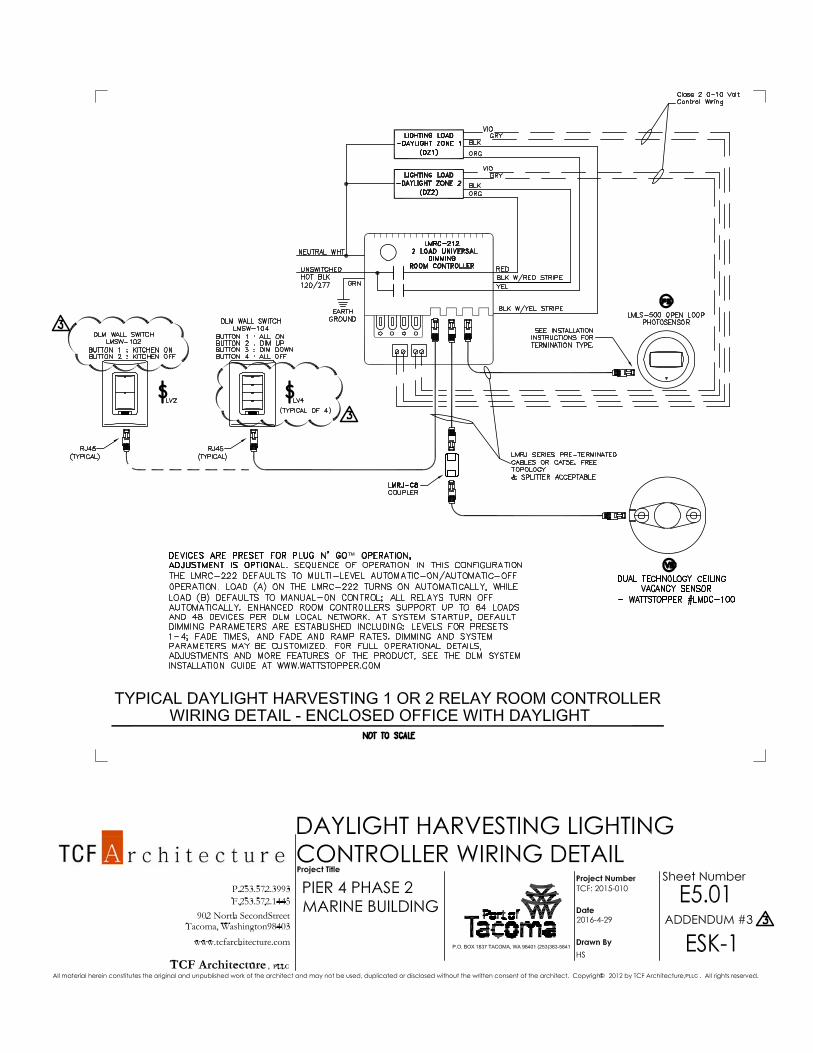
M. DRAWING E5.01 – MARINE BUILDING ELECTRICAL DETAILS (SHEET 494) – TYPICAL DAYLIGHT HARVESTING 1 OR 2 RELAY ROOM CONTROLLER WIRING DETAIL – ENCLOSED OFFICE WITH DAYLIGHT 1. REVISE low voltage switch LV2 to a two-button switch. Revise function to say KITCHEN ON
AND KITCHEN OFF. (See Attachment K to this Addendum No. 3) 2. REVISE low voltage switch LV4 to a four-button switch. (See Attachment K to this Addendum
No. 3)
Project No. 091251 00 91 11.03 - 5 Contract No. 070136

DIVISION 00 - PROCUREMENT AND CONTRACTING REQUIREMENTS SECTION 00 91 11.03 – ADDENDUM NUMBER THREE
Receipt for this addendum shall be indicated in the space provided in Section 00 41 00, Bid Form.
END OF SECTION
ATTACHMENTS: ATTACHMENT A - SECTION 00 41 00 BID FORM ATTACHMENT B - SECTION 26 22 13.01 DRY TYPE TRANSFORMER ATTACHMENT C - DRAWING G7.1 – EXISTING CONDITIONS PLAN (SHEET 11) ATTACHMENT D - DRAWING D1.2 – UTILITY AND SITE DEMOLITION PLAN – SHEET 2 (SHEET 21) ATTACHMENT E - DRAWING C3.1 – SLOPE PROTECTION PLAN (SHEET 52) ATTACHMENT F - DRAWING C3.3 – SLOPE PROTECTION SECTIONS – SHEET 2 (SHEET 54) ATTACHMENT G - DRAWING S4.2 – PILE AND PILE CAP PLAN – SHEET 2 (SHEET 180) ATTACHMENT H - DRAWING S27.45 – DECK PANEL DETAILS – SHEET 45 (SHEET 340) ATTACHMENT I - DRAWING S27.48 – DECK PANEL DETAILS – SHEET 48 (SHEET 343) ATTACHMENT J - DRAWING S36.1 CRANE STOP DETAILS (SHEET 369) ATTACHMENT K - ESK-1 Daylight Harvesting Lighting Controller Wiring Detail
Project No. 091251 00 91 11.03 - 6 Contract No. 070136

DIVISION 00 - PROCUREMENT AND CONTRACTING REQUIREMENTS SECTION 00 41 00 - BID FORM - ADDENDUM NO. 03
Project No. 091251 00 41 00 - 1 Contract No. 070136 Volume 1 of 3 - Project Manual
BIDDER'S NAME: PROJECT TITLE: PIER 4 PHASE 2 RECONFIGURATION
The undersigned Bidder declares that it has read the specifications, understands the conditions, has examined the site, and has determined for itself all situations affecting the work herein bid upon. Bidder proposes and agrees, if this bid is accepted, to provide at Bidder’s own expense, all labor, machinery, tools, materials, etc., including all work incidental to, or described or implied as incidental to such items, according to the bidding documents, and that the Bidder will complete the work within the time stated, and that Bidder will accept in full payment therefore the lump sums and unit prices set forth below.
Proposed Bid Price. (Note: Show prices in figures only.) Complete Installation:
ITEM NO. DESCRIPTION OF ITEM QTY UOM UNIT PRICE EXTENDED PRICE
1 Mobilization and Demobilization 1 LS
2 Project Administration 1 LS
3 Field Engineering 1 LS
4 Demolition 1 LS
5 Exploratory Excavation 1,160 CY
6 Removal of Buried Timber Bulkhead Wall 700 LF
7 Stone Columns 69,171 LF
8 Riprap and Debris Removal and Disposal 1 LS
9 Dredging and Disposal 465,000 CY
10 Filter Blanket 14,950 14,800 TON
11 Light Rock Riprap 32,500 32,200 TON
12 Heavy Rock Riprap 36,000 TON
13 Furnish 24-inch Concrete Pile 174,121 LF
14 Install 24-inch Concrete Pile - Wharf Plumb Piles 1,197 EA
15 Install 24-inch Concrete Pile - Wharf Batter Piles 36 EA
16 Install 24-inch Concrete Piles - Mooring Dolphin Piles 8 EA
17 Dynamic Pile Driving Analysis 20 EA

DIVISION 00 - PROCUREMENT AND CONTRACTING REQUIREMENTS SECTION 00 41 00 - BID FORM - ADDENDUM NO. 03
Project No. 091251 00 41 00 - 2 Contract No. 070136
ITEM NO. DESCRIPTION OF ITEM QTY UOM UNIT PRICE EXTENDED PRICE
18 Re-strike Concrete Piles 50 EA
19 Pile Cut-offs (lengths greater than 10 feet) 50 EA
20 Concrete Pile Build-ups 40 EA
21 Furnish and Install Sheet Piles 1,308 LF
22 Construct Mooring Dolphin 1 LS
23 Wharf Construction 1 LS
24 Wharf Fender System 1 LS
25 Furnish and Install Crane Rail 1 LS
26 Concrete Spall Repairs to Existing Pier 4 118 SF
27 Storm Drain, Water and Sanitary Sewer Systems 1 LS
28 Electrical and Communications Site Work 1 LS
29 Electrical Substation 1 LS
30 Ballast and Base Course for Asphalt Paving 17,940 TON
31 Asphalt Paving 22,220 TON
32 Marine Building 1 LS
33 All Other Work 1 LS
34 Stone Column Obstructions Allowance 1 LS $50,000 $50,000
35 Unforeseen Dredging Debris Removal Allowance 1 LS $100,000 $100,000
36 Unforeseen Conditions Allowance 1 LS $100,000 $100,000
37 Screened Dredging Premium Allowance 300 HR
BASE BID SUBTOTAL
Evaluation of Bids. In accordance with the provisions of these Contract Documents, Bids will be evaluated to determine the lowest Base Bid Subtotal offered by a responsible Bidder submitting a responsive bid.
DIVISION 00 - PROCUREMENT AND CONTRACTING REQUIREMENTS SECTION 00 41 00 - BID FORM - ADDENDUM NO. 03
Project No. 091251 00 41 00 - 3 Contract No. 070136
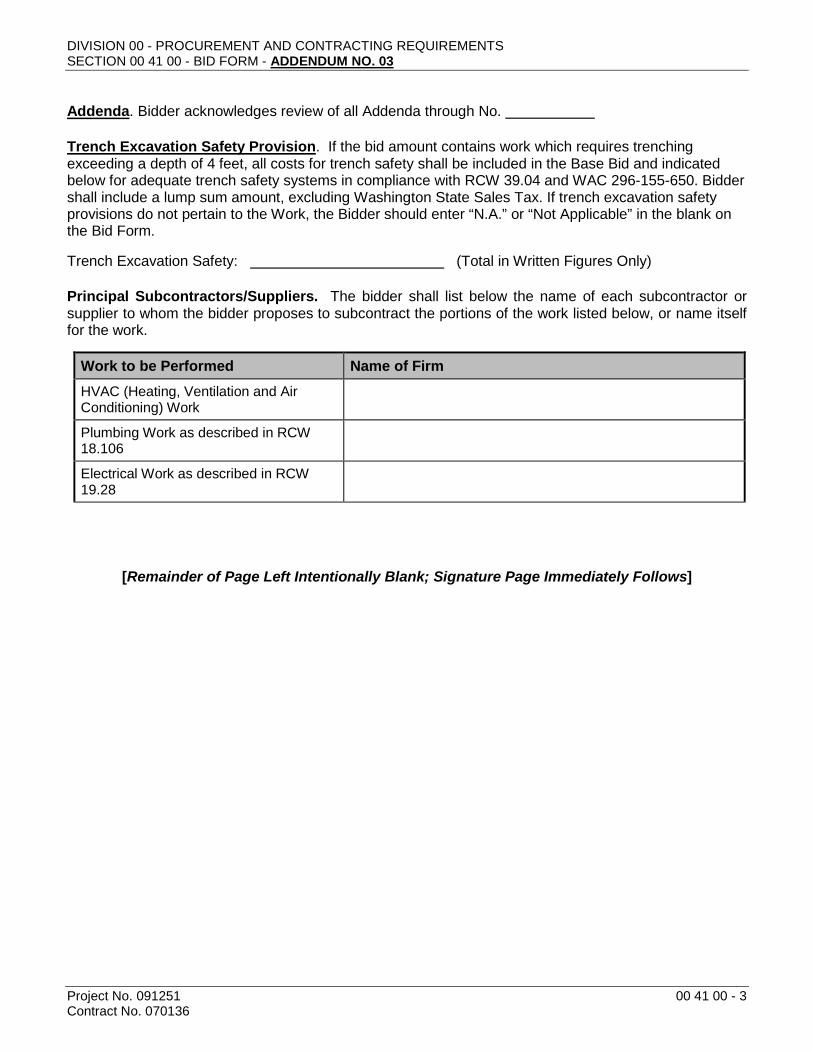
Addenda. Bidder acknowledges review of all Addenda through No.
Trench Excavation Safety Provision. If the bid amount contains work which requires trenching exceeding a depth of 4 feet, all costs for trench safety shall be included in the Base Bid and indicated below for adequate trench safety systems in compliance with RCW 39.04 and WAC 296-155-650. Bidder shall include a lump sum amount, excluding Washington State Sales Tax. If trench excavation safety provisions do not pertain to the Work, the Bidder should enter “N.A.” or “Not Applicable” in the blank on the Bid Form.
Trench Excavation Safety: (Total in Written Figures Only)
Principal Subcontractors/Suppliers. The bidder shall list below the name of each subcontractor or supplier to whom the bidder proposes to subcontract the portions of the work listed below, or name itself for the work.
Work to be Performed Name of Firm HVAC (Heating, Ventilation and Air Conditioning) Work
Plumbing Work as described in RCW 18.106
Electrical Work as described in RCW 19.28
[Remainder of Page Left Intentionally Blank; Signature Page Immediately Follows]
DIVISION 00 - PROCUREMENT AND CONTRACTING REQUIREMENTS SECTION 00 41 00 - BID FORM - ADDENDUM NO. 03
Project No. 091251 00 41 00 - 4 Contract No. 070136
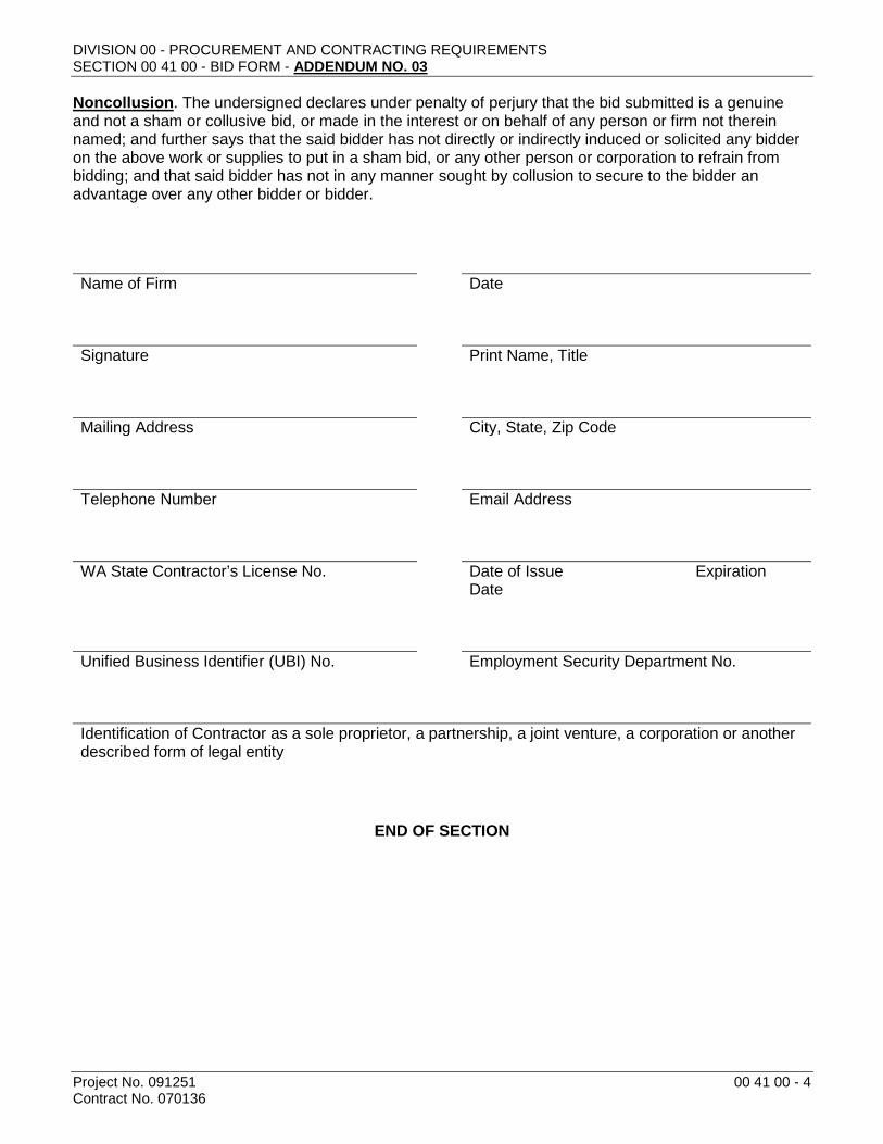
Noncollusion. The undersigned declares under penalty of perjury that the bid submitted is a genuine and not a sham or collusive bid, or made in the interest or on behalf of any person or firm not therein named; and further says that the said bidder has not directly or indirectly induced or solicited any bidder on the above work or supplies to put in a sham bid, or any other person or corporation to refrain from bidding; and that said bidder has not in any manner sought by collusion to secure to the bidder an advantage over any other bidder or bidder.
Name of Firm Date
Signature Print Name, Title
Mailing Address City, State, Zip Code
Telephone Number Email Address
WA State Contractor’s License No. Date of Issue Expiration
Date
Unified Business Identifier (UBI) No. Employment Security Department No.
Identification of Contractor as a sole proprietor, a partnership, a joint venture, a corporation or another described form of legal entity
END OF SECTION

DIVISION 26 – ELECTRICAL SECTION 26 22 13.01 – DRY TYPE TRANSFORMERS
Project No. 091251 Contract No. 070136
26 22 13.01 - 1
PART 1 - GENERAL
1.01 RELATED WORK SPECIFIED ELSEWHERE
A. The provisions and intent of the Contract, including the General Conditions and General Requirements, apply to this work as if specified in this section.
1.02 SCOPE
A. Furnish and install dry type isolation transformers of the types, sizes and quantities indicated on the contract drawings. Provide all lugs, accessories and mounting hardware necessary for proper installation and operation.
1.03 SUBMITTALS
A. Provide product information prior to fabrication and installation. Product data shall include all dimensions, weights, electrical ratings, wiring diagrams and required clearances.
B. When requested, provide additional product data and certifications necessary to show conformance with this specification.
C. Provide information for record purposes including field test reports and maintenance data as required.
PART 2 - PRODUCTS
2.01 ACCEPTABLE MANUFACTURERS
A. Tierney.
B. Sorgel Quiet Quality.
C. General Electric QL.
D. Federal Pacific.
E. Similar units by Cutler-Hammer, Acme or Hevi-Duty may be utilized if the core and coil assembly is mounted on rubber isolation pads.
2.02 STANDARDS
A. ANSI C57.12: General Requirements for Distribution, Power, and Regulating Transformers.
B. Underwriters Laboratories Standard 1561.
C. NEMA ST-20: Dry-Type Transformers for General Applications.
D. Transformers shall be NEMA TP-1 Energy Efficient compliant.
2.03 SHOP DRAWINGS
A. Prepare and submit for review prior to manufacture; include dimensioned front plan and section views, wiring and connection diagrams and bolting template. Contractor shall indicate on the drawings, mounting methods and connection lugs required.

DIVISION 26 – ELECTRICAL (MARINE BUILDING) SECTION 26 22 13.01 – DRY TYPE TRANSFORMERS
Project No. 091251 Contract No. 070136
26 22 13.01 - 2
2.04 CABINET
A. Steel panel enclosure over core, coil, and terminal chamber with louvered openings for convection cooling. Cooling and terminal access shall be possible with both sides and rear of enclosure obstructed.
B. Provide weatherproof or special enclosure when required for environment in which it is located.
2.05 WINDINGS
A. Separate primary and secondary. Windings shall have Class H insulation and shall be rated for continuous operation at rated KVA with temperature rise of not over 150 degrees C above a 40 degree C ambient, with a maximum hot spot temperature of 220 degrees C. Windings and core and coil assembly shall be treated and built to resist the effects of dirt and moisture.
B. Core coil shall be mounted on rubber isolation mounting pads. Cores shall have a common core construction having low hysterisis and eddy current losses grounded to the transformer core. The neutral bus shall be sized and configured for at least 200% of the secondary full load current. Transformer impedance shall be a minimum of 3 and a maximum of 5%. The transformer shall be UL listed and suitable for non-sinusoidal loads with a K factor of 4.
2.06 PRIMARY TAPS
A. Four full capacity taps, minimum of two 2-1/2 percent above and two 2-1/2 percent below normal (rated) primary voltage.
2.07 CONNECTIONS
A. Unless noted otherwise, three phase transformers shall have a 480 volt delta connected primary and 208Y/120 volt, three phase, four wire connected secondary, single phase transformers shall be 480 volt primary, 120/240 volt secondary. Provisions for external connections shall be made by means of a terminal board employing lugs conforming with Section 26 05 19 which are compatible with the external conductors installed. (Note: aluminum conductors require special lugs.) All connections shall be accessible for front and top of cabinet.
2.08 NOISE LEVEL
A. Noise level shall not exceed ANSI Standard C89.2 sound levels of 45 db for sizes less than 51 KVA, 50 db for 51-150 KVA, 55 db for 151-300 and 60 db for greater than 300 as measured by NEMA ST20.
2.09 EFFECIENCY
A. Dry transformers shall have a minimum efficiency that complies with NEMA TP-1-2002.
2.10 VIBRATION ISOLATORS
A. Spring vibration isolators shall be B-Line model HMT or equal with neoprene top and base.
B. Vibration pads shall be cork, neoprene, and steel construction, B-Line model CNNK or equal.

DIVISION 26 – ELECTRICAL (MARINE BUILDING) SECTION 26 22 13.01 – DRY TYPE TRANSFORMERS
Project No. 091251 Contract No. 070136
26 22 13.01 - 3
C. Neoprene pad spacers shall be B-Line model NNP or equal.
PART 3 - EXECUTION
3.01 MOUNTING
A. Transformers shall be attached to the building structure to prevent overturning in the event of earthquake. All attachment nuts to have washer and rubber pad spacer under them. Provide neoprene pad spacers under mounting rails. Transformers shall be mounted on floor, wall or suspended from ceiling as noted in the contract documents or as required. Remove all shipping blocks prior to installation.
B. Transformers with enclosures designed for floor mounting where suspended from ceiling shall be suspended on a trapeze constructed of a minimum of two horizontal structural channels hung from threaded rods attached to structural members or inserts in structural slab. Channel, rod, and inserts shall be sized for not less than 400% load safety factor.
C. Transformers shall be installed with four spring vibration isolators, one at each corner, when any of the following conditions are present. Size each isolator for the full transformer weight.
1. Transformer is 45 KVA or larger.
2. Transformer is located higher than one floor above grade.
3. Transformer is noted "SIM" in the contract documents.
D. All transformers mounted directly on a wall shall be mounted with vibration pads sized to give 400% safety factor.
3.02 CONNECTIONS
A. 208/120 volt three phase secondary transformers shall be considered "grounded neutral separately derived systems" and be grounded per code accordingly.
B. Transformer raceway connections shall be flexible metal raceway. See Specification Section 26 05 33.
C. Voltage Tap Connection: Connect all transformers at "normal" tap. After facility is completely energized, measure secondary voltages at all transformers and service switchboard. Forward a list to the Engineer for evaluation. Include copy in O&M Manuals. Reconnect taps as subsequently directed.
END OF SECTION