tmc 303 underwater examination of structures 030: 2014 page 1 of 1 for queries regarding this...
TRANSCRIPT

TN 030: 2014
Page 1 of 1
For queries regarding this document [email protected]
www.asa.transport.nsw.gov.au
Technical Note TN 030: 2014
Issued date 16 April 2014 Effective date 16 April 2014
Subject: Withdrawal of TMC 303 Underwater Examination of Structures
This technical note is issued by the Asset Standards Authority as a notification to remove from
use RailCorp document TMC 303 Underwater Examination of Structures, Version 1.1.
TMC 303 is a legacy document and should be used for reference purposes only. ASA standard
T HR CI 12005 ST Underwater Examination of Structures, Version 1.0 supersedes this
document.
Authorisation
Technical content prepared by
Checked and approved by
Interdisciplinary coordination checked by
Authorised for release
Signature N/A
Name N/A Richard Hitch David Spiteri Graham Bradshaw
Position N/A Lead Civil Engineer Chief Engineer Rail Principal Manager Network Standards & Services
Asset Standards Authority 2014 Technical Note TMC 303 Underwater Examination of Structures © State of NSW through Transport for NSW

Sup
erse
ded
by T
HR
CI 1
2005
ST
Engi
neer
ing
Man
ual
UNDERWATER EXAMINATION OF STRUCTURES
TMC 303
Engineering Manual Structures
Version 1.1
Issued December 2009
Owner: Chief Engineer Civil
Approved by: John Stapleton Authorised by: Richard Hitch Group Leader Standards Chief Engineer Civil
Civil
Disclaimer This document was prepared for use on the RailCorp Network only. RailCorp makes no warranties, express or implied, that compliance with the contents of this document shall be sufficient to ensure safe systems or work or operation. It is the document user’s sole responsibility to ensure that the copy of the document it is viewing is the current version of the document as in use by RailCorp. RailCorp accepts no liability whatsoever in relation to the use of this document by any party, and RailCorp excludes any liability which arises in any manner by the use of this document. Copyright The information in this document is protected by Copyright and no part of this document may be reproduced, altered, stored or transmitted by any person without the prior consent of RailCorp
UNCONTROLLED WHEN PRINTED Page 1 of 30

Sup
erse
ded
by T
HR
CI 1
2005
ST
RailCorp Engineering Manual — Structures Underwater Examination of Structures TMC 303
Document control Revision Date of Approval Summary of change
1.1 December 2009 Changes detailed in chapter revisions
1.0 October 2007 First issue as a RailCorp document
Summary of changes from previous version Chapter Current Revision Summary of change
Control pages
1.1 Change of format for front page, change history and table of contents
1 1.1 Format change only 2 1.1 Format change only 3 1.1 Format change only 4 1.1 Format change only 5 1.1 Format change only 6 1.1 Format change only
Appendix 1 1.1 Format change only Appendix 2 1.1 Format change only Appendix 3 1.1 Format change only
© Rail Corporation Page 2 of 30 Issued December 2009 UNCONTROLLED WHEN PRINTED Version 1.1

Sup
erse
ded
by T
HR
CI 1
2005
ST
RailCorp Engineering Manual — Structures Underwater Examination of Structures TMC 303
© Rail Corporation Issued December 2009 UNCONTROLLED WHEN PRINTED
PagVe
e 3 of 30 rsion 1.1
Contents Chapter 1 General....................................................................................................................................... 4
C1-1 Purpose....................................................................................................................................... 4 C1-2 The structure of this manual ....................................................................................................... 4 C1-3 Who should use this manual....................................................................................................... 4 C1-4 References.................................................................................................................................. 4 C1-5 Terminology ................................................................................................................................ 4
Chapter 2 General requirements............................................................................................................... 5
C2-1 Introduction ................................................................................................................................. 5 C2-2 Purpose....................................................................................................................................... 5 C2-3 Structures requiring underwater examination .............................................................................5 C2-4 Scope and frequency .................................................................................................................. 5 C2-5 Personnel & equipment............................................................................................................... 5 C2-6 Classification and numbering of bridge elements....................................................................... 6
Chapter 3 Cleaning methods..................................................................................................................... 7
C3-1 Cleaning of marine growth .......................................................................................................... 7 C3-2 High pressure water cleaning (hydro blasting) ........................................................................... 7 C3-3 Air chipper cleaning (hydraulic)................................................................................................... 7 C3-4 Hand cleaning ............................................................................................................................. 8
Chapter 4 Identification of defects............................................................................................................ 9
C4-1 General ....................................................................................................................................... 9 C4-2 Concrete structures..................................................................................................................... 9 C4-3 Steel structures ......................................................................................................................... 10 C4-4 Brickwork, blockwork and masonry ..........................................................................................10 C4-5 Accuracy of measurements ......................................................................................................10 C4-6 Bed profiles and radial soundings.............................................................................................11
Chapter 5 Tender documentation ........................................................................................................... 13
C5-1 Requests for Quotation ............................................................................................................. 13
Chapter 6 Reporting and documentation............................................................................................... 14
C6-1 General ..................................................................................................................................... 14 C6-2 Urgent items.............................................................................................................................. 14 C6-3 Drawings ................................................................................................................................... 14 C6-4 Photographs.............................................................................................................................. 14 C6-5 Video survey .............................................................................................................................14 C6-6 Water sampling and analysis ....................................................................................................14 C6-7 Concrete & masonry core sampling and analysis.....................................................................15 C6-8 Metal sampling and analysis..................................................................................................... 15 C6-9 Appendices ............................................................................................................................... 15 C6-10 Signing of reports...................................................................................................................... 15
Appendix 1 Structures requiring underwater examinations................................................................... 17
Appendix 2 Sample Request for Quotation (RFQ) document................................................................. 19
Appendix 3 Typical report layout............................................................................................................... 23

Sup
erse
ded
by T
HR
CI 1
2005
ST
RailCorp Engineering Manual — Structures Underwater Examination of Structures TMC 303
Chapter 1 General C1-1 Purpose
This Manual details standard procedures to be followed for the examination of underwater components of structures within RailCorp’s network. The structures concerned are principally underbridges but also include transmission tower footings.
The procedures cover requirements for cleaning, inspection, reporting and assessment.
This Manual forms part of the suite of Manuals covering the examination and repair of RailCorp’s structures.
C1-2 The structure of this manual The Manual is laid out as follows:
− General requirements
− Cleaning methods
− Extent of examinations
− Reporting requirements
− Appendices (list of structures, schedule of rates and sample report)
C1-3 Who should use this manual This Manual should be used by RailCorp personnel:
− responsible for the preparation of technical specifications for the underwater examination of structures;
− responsible for the supervision of underwater examination contracts;
− responsible for the assessment of underwater examination reports and the implementation of remedial action/ structural repairs as required.
C1-4 References TMC 302 Volume 1 “Structures Repair Manual - General Requirements”
ESC 300 “Structures System”
ESC 302 “Defect Limits”
AS/NZS 2299.1 Occupational Diving Operations – Standard Operational Practice
C1-5 Terminology Specific terminology used in this Manual is defined as follows:
Contractor: Diving Company with demonstrated technical competency in underwater cleaning and inspection.
RailCorp Representative: Person with relevant technical competency in the structures discipline. May be the Manager of Civil discipline personnel in a District or as nominated by the Manager.
Defect: Deterioration of a component from its original condition.
Defect Category: Classification of a defect into a category that indicates the severity of the defect and response time recommended for continuing train operations and engineering assessment.
High Water Level (HWL): Adopted as the permanent watermark on a structure
Repair Priority: Time frame for the repair of a defect.
© Rail Corporation Page 4 of 30 Issued December 2009 UNCONTROLLED WHEN PRINTED Version 1.1

Sup
erse
ded
by T
HR
CI 1
2005
ST
RailCorp Engineering Manual — Structures Underwater Examination of Structures TMC 303
Chapter 2 General requirements C2-1 Introduction
The procedures within this Manual cover the underwater cleaning of marine growth, inspection, reporting and assessment of components of railway structures that are permanently submerged in water.
Where the structure is located in tidal water, the submerged area is defined as that area below the high water level (HWL).
C2-2 Purpose The purpose of underwater examination of a structure is to:
− Review and record the condition of the structure;
− Identify defects and record any significant change in the condition, loading or environment factors that may cause deterioration;
− Ascertain the rate of deterioration by reference to the previous inspection reports;
− Identify the category, urgency and estimated cost of any remedial actions required;
− Provide sufficient information for the safe management of the structure and for any management action necessary to maintain the safety and serviceability of the structure;
− Provide information for regulatory reporting, where applicable.
C2-3 Structures requiring underwater examination Underbridges and transmission tower footings within the RailCorp network that require regular underwater examinations are listed in Appendix 1.
C2-4 Scope and frequency The underwater examinations are to be undertaken on a six-year cycle, unless otherwise indicated on the previous report for the particular structure.
There may be a need to examine a structure upon demand following a bridge strike or other ‘force majeure’. Requirements for such an examination are to be determined in accordance with the particular circumstances.
Each examination may require, but not be limited to:
− Removing debris from the vicinity of the structure;
− Removing marine growth from the designated parts of the substructure to facilitate inspection;
− Providing photographs and diagrams of defects;
− A full defect survey of cleaned surfaces;
− Channel bed profiling;
− Video camera survey;
− Water sampling;
− Material sampling.
C2-5 Personnel & equipment All underwater inspections are to be undertaken by appropriately qualified divers in accordance with the requirements of the WorkCover Authority of NSW and Australian Standard AS/NZS 2299.1 “Occupational Diving Operations – Standard Operational Practice”. All apparatus used and procedures followed during diving shall conform to the requirements of AS/NZS 2299.1.
A minimum 3-person crew comprising the Dive Supervisor, Examining Diver and Stand-By Diver shall be provided during all diving work.
© Rail Corporation Page 5 of 30 Issued December 2009 UNCONTROLLED WHEN PRINTED Version 1.1

Sup
erse
ded
by T
HR
CI 1
2005
ST
The role, responsibilities and qualifications of the Dive Supervisor and the Examining Diver are outlined in Section 2.1 & 2.2 respectively of AS/NZS 2299.1. In addition, the Examining Diver shall have relevant experience in underwater inspections of bridge substructures.
C2-6 Classification and numbering of bridge elements The standard system for the description and numbering of bridge elements is provided in Engineering Standard ESC 300 “Structures System”. Specific elements involved in underwater examinations are illustrated in Fig 1.1. The pile configuration shall be identified and referenced as shown in Figure 1.2 and 1.3.
Abutment No.1 Pier No.1 Pier No.2
Sydney Country
Fig.1.1: Abutment and Pier Numbering
Row A B C
B1
A1 C1
B2 Country
A2 C2
B3 SydneyC3A3
B4
Fig. 1.2: Pile Numbering
02
Country Sydney 01 03
04
RailCorp Engineering Manual — Structures Underwater Examination of Structures TMC 303
Abutment No.2
Fig. 1.3: Pile Face Numbering (Square and Circular)
© Rail Corporation Page 6 of 30 Issued December 2009 UNCONTROLLED WHEN PRINTED Version 1.1
Sup
erse
ded
by T
HR
CI 1
2005
ST
RailCorp Engineering Manual — Structures Underwater Examination of Structures TMC 303
Chapter 3 Cleaning methods C3-1 Cleaning of marine growth
Prior to inspection, crustaceans and other marine growth shall be removed from a determined proportion of the substructure components underwater (or within the splash zone) by high pressure water cleaning, by air chipper cleaning or by hand cleaning.
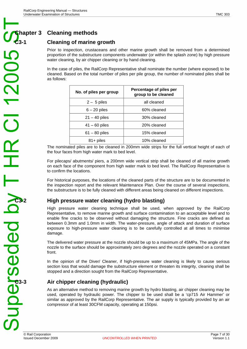
In the case of piles, the RailCorp Representative shall nominate the number (where exposed) to be cleaned. Based on the total number of piles per pile group, the number of nominated piles shall be as follows:
No. of piles per group Percentage of piles per group to be cleaned
2 – 5 piles all cleaned
6 – 20 piles 60% cleaned
21 – 40 piles 30% cleaned
41 – 60 piles 20% cleaned
61 – 80 piles 15% cleaned
81+ piles 10% cleaned The nominated piles are to be cleaned in 200mm wide strips for the full vertical height of each of the four faces from high water mark to bed level.
For pilecaps/ abutments/ piers, a 200mm wide vertical strip shall be cleaned of all marine growth on each face of the component from high water mark to bed level. The RailCorp Representative is to confirm the locations.
For historical purposes, the locations of the cleaned parts of the structure are to be documented in the inspection report and the relevant Maintenance Plan. Over the course of several inspections, the substructure is to be fully cleaned with different areas being cleaned on different inspections.
C3-2 High pressure water cleaning (hydro blasting) High pressure water cleaning technique shall be used, when approved by the RailCorp Representative, to remove marine growth and surface contamination to an acceptable level and to enable fine cracks to be observed without damaging the structure. Fine cracks are defined as between 0.3mm and 1.0mm in width. The water-pressure, angle of attack and duration of surface exposure to high-pressure water cleaning is to be carefully controlled at all times to minimise damage.
The delivered water pressure at the nozzle should be up to a maximum of 45MPa. The angle of the nozzle to the surface should be approximately zero degrees and the nozzle operated on a constant front.
In the opinion of the Diver/ Cleaner, if high-pressure water cleaning is likely to cause serious section loss that would damage the substructure element or threaten its integrity, cleaning shall be stopped and a direction sought from the RailCorp Representative.
C3-3 Air chipper cleaning (hydraulic) As an alternative method to removing marine growth by hydro blasting, air chipper cleaning may be used, operated by hydraulic power. The chipper to be used shall be a ‘cp715 Air Hammer’ or similar as approved by the RailCorp Representative. The air supply is typically provided by an air compressor of at least 30CFM capacity, operating at 150psi.
© Rail Corporation Page 7 of 30 Issued December 2009 UNCONTROLLED WHEN PRINTED Version 1.1

Sup
erse
ded
by T
HR
CI 1
2005
ST
C3-4 Hand cleaning
RailCorp Engineering Manual — Structures Underwater Examination of Structures TMC 303
Hand cleaning techniques using scrapers and wire brushes may be deemed adequate for smaller structures, or where the thickness of marine growth is small.
© Rail Corporation Page 8 of 30 Issued December 2009 UNCONTROLLED WHEN PRINTED Version 1.1

Sup
erse
ded
by T
HR
CI 1
2005
ST
RailCorp Engineering Manual — Structures Underwater Examination of Structures TMC 303
Chapter 4 Identification of defects C4-1 General
Each underwater inspection shall identify any Defects as follows:
− Deformation of the substructure;
− Parts of the structure that are out of plumb, hogging/sagging, misaligned, buckled, or otherwise distorted;
− Parts of the structure that are missing;
− Movement, distortion and condition of connections between elements;
− Condition of all foundation bases or piles above bed level;
− Evidence of foundation movement, sliding or settlement affecting the structure;
− Signs of subsidence, heave, misalignment, cracking or movement of the ground;
− Movement at construction joints such as the interface between pile(s) and cap, abutment and footing/apron, the pier and cutwater nosing;
− Excessive wear due to exposure to water;
− Unsafe access or egress facilities;
− Significant accidental damage, including that due to bridge strikes from water traffic;
− Railway materials and other large items of rubbish deposited on the channel bed;
− Presence of vegetation which might affect the structure;
− Significant vandalism, graffiti, or trespass;
− The area and location of any repair, repainting or renewal work carried out since the last detailed examination, and any work in progress or change of construction not previously recorded;
− Defects in monitoring equipment attached to the structure including flood gauges and fracture tabs (if applicable);
− Bed material (approximate grading of sand, silt, clay, gravel or a combination of these);
− Flooding or evidence of flooding;
− Localised bed scouring;
− Undermining to the substructure.
C4-2 Concrete structures For concrete structures, the following shall also apply.
In general, concrete degrades in the following ways:
− Weathering or spalling at exposed faces (particularly within the tidal/splash zone), resulting from erosion, poor quality concrete, chemical action, water action, corrosion of reinforcement, cover of reinforcement bars, crushing at bearing surfaces, and drumminess.
− Cracking from loading changes, including settlement.
Based on this, concrete elements and the conditions of any protective treatment shall be examined.
Staining from corroding reinforcement, spalling and any exposed reinforcement shall be recorded. The area, depth and location of spalling shall be measured, and the sizes of exposed reinforcement bars and the amount of corrosion shall be recorded.
Cracks or fractures shall be cleaned, the locations recorded, the widths and depth (where visible) measured, and evidence of cause and likely age of the fracture logged. The fracture survey shall continue into the area deemed not normally under water, to give a complete fracture profile.
© Rail Corporation Page 9 of 30 Issued December 2009 UNCONTROLLED WHEN PRINTED Version 1.1

Sup
erse
ded
by T
HR
CI 1
2005
ST
RailCorp Engineering Manual — Structures Underwater Examination of Structures TMC 303
Any rust, leaching or other stains, crazing, cracks or honeycombing shall be recorded.
Where it is suspected that the concrete has been affected by loss of cement, chemical attack or other significant change during placing, curing or subsequent to construction, evidence of softening, crumbling or deterioration of the surface shall be recorded.
Concrete surfaces shall be sounded with a hammer to identify the presence and extent of delamination from reinforcement, drumminess and potential spalling areas, which shall be recorded.
Faulty construction including formwork not fully removed, lack of concrete cover to steelwork, inadequate curing and poor casting shall be logged.
C4-3 Steel structures For steel structures, the following shall also apply.
In general, steel deteriorates in service in the following ways:
− Erosion or corrosion at exposed surfaces, and at timber and concrete interfaces;
− Cracking in members or welds;
Based on this, all metalwork shall be examined underwater for corrosion. Any loss of metal due to corrosion shall be measured, or if not reasonably practicable, the reduced dimensions of metallic elements shall be estimated. Particular attention is to be paid to splices in members and other joints or connections and cracked welds.
Particular attention shall be paid to cracks and graphitic corrosion in cast iron elements. The range of graphitic corrosion shall be measured and the bed level excavated 100mm to check for corrosion covered by bed material. The depth of corrosion shall be measured and an assessment made of the total area affected by corrosion.
New or developing cracks shall be reported immediately to the RailCorp Representative. Cast iron elements shall not be struck to check for integrity.
In addition to general corrosion, particular attention shall be made to the corrosion of rivets and bolts, identifying any loose connection, any loose or displaced banding on cylinder piers, and areas in the tidal or splash zone.
The length and orientation of cracks in any metal element shall be recorded.
The condition of the protective treatment (including paintwork and galvanising) shall be recorded, including any damage caused during the inspection. The date of the last painting, if known, shall be recorded.
C4-4 Brickwork, blockwork and masonry For brick, blockwork & masonry structures, the following shall also apply.
Brickwork, blockwork and masonry shall be examined for open joints, looseness, cracks, spalling, bulging, crushing and deterioration of pointing, leaching or stains. The brickwork, blockwork or masonry shall be sounded with a hammer to identify the presence and extent of internal voids that may have formed.
The positions, extent, width, depth, orientation and total area of defects shall be measured, or estimated if not practical, and recorded.
C4-5 Accuracy of measurements All defects shall be recorded to the following accuracy:
− Location and depth of defects below water level ±200mm;
− Crack widths shall be estimated to ±1mm;
© Rail Corporation Page 10 of 30 Issued December 2009 UNCONTROLLED WHEN PRINTED Version 1.1

Sup
erse
ded
by T
HR
CI 1
2005
ST
RailCorp Engineering Manual — Structures Underwater Examination of Structures TMC 303
− Width and depth of spalls shall be measured to ±10mm;
− Length of cracks or overall dimensions of deteriorated features shall be measured to ±10mm.
Colour, texture and abnormalities shall also be described.
C4-6 Bed profiles and radial soundings For major structures or after major flooding, there may be a need to undertake bed level surveys radially around piers and at sections across the watercourse. Typically, the datum point is deemed to be either the underside of the main girder (if reasonably low), underside of the headstock, or top of the pile cap (if above HWL).
A minimum of four cross-sections should be surveyed, one along each face of the bridge, one at the centre line and a further cross section at approximately 30m upstream from the bridge. Where the structure is located within a tidal zone, a fifth cross section should be taken at approximately 30m downstream of the structure.
30m Upstream
Centreline
Downstream Face
Upstream Face
30m Downstream (Tidal Affected Structures only)
Flow
Fig. 1.4: Plan View of Structure with Cross Sectional Bed Profiling Locations
Radial levels may also be taken around nominated piers/piles and abutments under permanent water or within the tidal zone. Four readings are to be taken at each radial, one at the pier face, the second 1m away, the third 2m away and the fourth 3m away from the pier face. Examples of radial locations are given in fig 1.5.
Sydney
R1
R2R4
Country
R3
Fig. 1.5: Location and numbering of radials around columns and piles
© Rail Corporation Page 11 of 30 Issued December 2009 UNCONTROLLED WHEN PRINTED Version 1.1
Sup
erse
ded
by T
HR
CI 1
2005
ST
RailCorp Engineering Manual — Structures Underwater Examination of Structures TMC 303
The number of cross-sections, frequency and location of readings and radials shall be agreed with the RailCorp Representative prior to inspection.
The levels of any marks provided on each structure, to facilitate closure in times of flood, shall be recorded.
The water level at the time of inspection is to be recorded as a vertical distance from the datum point, expressed in metres to an accuracy of ±100mm. All sounding measurements are to be recorded to an accuracy of ±100mm.
Details and data obtained are to be entered into an Excel spreadsheet with line graphs illustrating cross-section bed profiles and bed depths surrounding pier elements. A comparison should be made against the previously recorded bed levels.
Comments should be made as to the profiles and any scouring or undermining to the substructure, particularly with reference to the previous examinations and any differences.
© Rail Corporation Page 12 of 30 Issued December 2009 UNCONTROLLED WHEN PRINTED Version 1.1

Sup
erse
ded
by T
HR
CI 1
2005
ST
RailCorp Engineering Manual — Structures Underwater Examination of Structures TMC 303
Chapter 5 Tender documentation C5-1 Requests for Quotation
As stated in Section 2-5, underwater examinations are to be undertaken by qualified divers. If RailCorp does not have suitably qualified employees, the work will require to be undertaken by contract.
A typical technical specification and tender schedule is provided in Appendix 2. These documents should be used as a basis when preparing tender documentation (requests for quotation) for specific examinations.
© Rail Corporation Page 13 of 30 Issued December 2009 UNCONTROLLED WHEN PRINTED Version 1.1

Sup
erse
ded
by T
HR
CI 1
2005
ST
RailCorp Engineering Manual — Structures Underwater Examination of Structures TMC 303
Chapter 6 Reporting and documentation C6-1 General
The results of all underwater inspections are to be recorded in electronic format on the prescribed inspection report forms. These forms provide for the recording of relevant data and information on the structure.
Within one month of the completion of the underwater inspection of a bridge, the Contractor/ Diver shall provide a completed underwater inspection report, including the detailed inspection logs, photographs, sketches, video camera tapes (where applicable) and all other required information for that bridge. The report is to be submitted to the RailCorp Representative, who is required to analyse the findings, determine any necessary action and assign a Repair Priority as appropriate (refer to Engineering Standard ESC 302 “Defect Limits”).
A summary of the RailCorp Representative’s review is to be attached as a cover sheet to the original report.
A typical report layout is provided for guidance in Appendix 3.
C6-2 Urgent items Where the condition of any part of a structure is such that urgent action is likely to be required or has been taken, the RailCorp Representative shall be informed verbally or electronically as soon as practically possible, prior to submission of the written report.
C6-3 Drawings Where defects have been identified, diagrams are to be produced and incorporated in the report, highlighting the extent and locations.
C6-4 Photographs Colour photographs shall be provided in all underwater inspection reports. The location and orientation of all photographs shall be numbered, annotated and dated to identify the particular item.
Reports shall include sufficient photographs to show or provide clarification of the following:
− Any significant defect;
− Features which the diver/ author considers to require amplification;
− Details or components that are only visible using access equipment provided for the inspection;
− Difficulties with access and reason for not examining a particular element of a structure;
− Limitation: any item that may have been missed during the inspection.
C6-5 Video survey A full video survey may be required covering all areas/surfaces cleaned. The survey is to be recorded in real time and with divers’ commentary over all cleaned parts of the structure.
C6-6 Water sampling and analysis If requested by the RailCorp Representative, a representative 1.0 litre sample of the water shall be taken in an uncontaminated container and sent to an approved NATA accredited laboratory for chemical analysis. The results including conductivity, pH value and the amount of chlorides, sulphates and sodium shall be covered in the report.
© Rail Corporation Page 14 of 30 Issued December 2009 UNCONTROLLED WHEN PRINTED Version 1.1

Sup
erse
ded
by T
HR
CI 1
2005
ST
RailCorp Engineering Manual — Structures Underwater Examination of Structures TMC 303
C6-7 Concrete & masonry core sampling and analysis The RailCorp Representative may require concrete cores to be taken for testing. The cores shall be sent to a NATA laboratory for analysis and the results included in the report.
C6-8 Metal sampling and analysis The RailCorp Representative may require metallic materials to be tested, in which case the elements, locations and dimensions shall be nominated. The samples shall be sent to a NATA laboratory for analysis and the results included in the report.
C6-9 Appendices For all underwater inspections, the following documents should be included as appendices:
− The diver’s logs;
− A record of all operations on site, times and depth under water and details of the persons performing the various roles;
− Any problems encountered, keys required and permission to access land.
C6-10 Signing of reports The front page summary of each report is to be signed and dated by the RailCorp Representative. Signatures shall be manuscript on hard copies of the reports.
If a report requires amendment after it has been issued, the report shall be re-issued and clearly identified as a revision, superseding the previous report. The amended report shall be subject to review and signature as for an original report.
© Rail Corporation Page 15 of 30 Issued December 2009 UNCONTROLLED WHEN PRINTED Version 1.1

Sup
erse
ded
by T
HR
CI 1
2005
ST

Sup
erse
ded
by T
HR
CI 1
2005
ST
© Rail Corporation Page 17 of 30 Issued December 2009 UNCONTROLLED WHEN PRINTED Version 1.1
RailCorp Engineering Manual — Structures Underwater Examination of Structures TMC 303
Appendix 1 Structures requiring underwater examinations The following structures within the RailCorp network require underwater examinations:
A. UNDERBRIDGES
KM Structure Name Structure Plant No. Number of piers under
water
Number & diameter of
piles per pier
Total depth of pile below water
Maximum water depth
1 7.003km Cooks River (Tempe Locals) I00UB10113LOCALS_7.003
2 7.006km Cooks River (Tempe Mains) I00UB10113MAINS_7.006
3 18.377km Salt Pan Creek (Riverwood) M25UB10081ALLT_18.377
4 24.357km Georges River (East Hills) M25UB10081ALLT_24.357
5 19.925km Georges River, Como I00UB10113MAIN_19.929
6 86.807km Allen's Creek, Lysaghts I10UB10122MAIN_86.807
7 101.100km Macquarie Rivulet – Yallah I00UB10118SNGL_101.100
8 112.468km Minnamurra River, Minnamurra I00UB10118SNGL_112.468
9 17.500km (new) Meadowbank (Parramatta River) N00UB10002ALLT_17.500
10 17.500km (old) Meadowbank (Parramatta River) N00UB10002ALLT_17.500
11 58.463km (new) Hawkesbury River N00UB10002MAIN_58.463
12 58.463km (old) Hawkesbury River N00UB10002MAIN_58.463
13 70.330km Woy Woy (Parkes Bay, Gosford) N00UB10002ALLT_70.330
14 79.844km Gosford Broadwater N00UB10002MAIN_79.844
15 96.802km Ourimbah Creek, Ourimbah N00UB10002ALLT_96.802
16 100.480km Wyong Creek, Wyong. N00UB10002ALLT_100.480
17 127.769km Dora Creek. N00UB10002ALLT_127.769
18 150.540km Cockle Creek. N00UB10002MAIN_150.540

Sup
erse
ded
by T
HR
CI 1
2005
ST
KM Structure Name Structure Plant No. Number of piers under
water
Number & diameter of
piles per pier
Total depth of pile below
water
Maximum water
depth
19 115.131km Mannering Creek (Wyee). N00UB10002ALLT_115.131
20 10.423km Cooks River (Canterbury) M24UB10087MAIN_10.423
21 10.423km Cooks River (Canterbury) M52UB10087GOOD_10.423
22 13.991km Mascot - Shea's Ck UB (Alexandria Canal) M50UB10089ALLT__13.991
23 17.815km Lidcombe - Haslams Crk UB S00UB10043MAIN__17.815
24 30.722km Georges River West M25UB10081ALLT_30.722
25 23.365km Parramatta River (Rydalmere) M13UB10154ALLT_23.365
26 53.250km South Creek (Mulgrave) M17UB10191SNGL_53.250
27 56.371km Nepean River (Emu Plains) W00UB10177MAIN_56.371
RailCorp Engineering Manual — Structures Underwater Examination of Structures TMC 303
B. TRANSMISSION TOWERS Footings for the SRA Pole Numbers 16, 20-24, 28, 31-32, 34-36, 38, 42-44, 47, 55 and 57 between Hawkesbury River and Woy Woy beside the Main Northern Line between 61.197km and 65.597km.
© Rail Corporation Page 18 of 30 Issued December 2009 UNCONTROLLED WHEN PRINTED Version 1.1

Sup
erse
ded
by T
HR
CI 1
2005
ST
RailCorp Engineering Manual — Structures Underwater Examination of Structures TMC 303
Appendix 2 Sample Request for Quotation (RFQ) document PART D (TECHNICAL SPECIFICATION)
D1.0 Location and Description of Underbridge Insert here a brief description of the bridge to be inspected (location, kilometrage, configuration etc.), together with photos if available.
D2.0 Extent of Work Insert here the proposed scope of work by the Contractor, e.g.:
The works under the Contract include the following items which shall be carried out in their entirety in strict accordance with this specification and to the true intent and purpose of the conditions of contract:
− Prepare and implement site specific OHS&R plan;
− Prepare and implement site specific environmental management plan (“EMP”) in accordance with all relevant required approvals;
− Prepare and implement site specific Rail Safety Plan;
− Provision of all site facilities as required;
− Supply of water and electrical services as required;
− Provide all plans and logistics and undertake inspection of bridge piers permanently underwater including splash zone in accordance with the requirement this RFQ document;
− Clean all nominated piles, pile caps and piers off crustacean and marine growth by acceptable methods in accordance with this RFQ document ;
− Measure and report the depth of bed level at each nominated pier;
− Undertake full cross section bed profile of channel bed relative to fixed datum point & HWL.
− Video camera logging of all nominated piles and submerged sections of all piers and abutments;
− Remove and disposal of all debris and imported material from site;
− Full Site restoration;
− Provision of Protection Officer Class 4 during site works (if required) and submission of a RailCorp-approved rail safety plan for each site;
− Prepare and submit report incorporating all field observations and any other works approved by RailCorp Representative.
Notes: 1. No Contract work shall commence without the RailCorp Representative being present. 2. The Contractor shall submit the following documentation and obtain the approval of the
RailCorp Representative prior to commencing Contract activities on site (including site establishment):
∼ Site specific OHS&R Plan; ∼ EMP;
∼ Rail Safety Plan; and ∼ Copies of approvals from all relevant authorities for the above.
3. The Contractor shall allow 2 weeks from the date of document submission for the RailCorp Representative to grant approval or request changes or additions to the document.
D3.0 Access to Site Describe here the means of access to the site. Include a map if available.
© Rail Corporation Page 19 of 30 Issued December 2009 UNCONTROLLED WHEN PRINTED Version 1.1

Sup
erse
ded
by T
HR
CI 1
2005
ST
RailCorp Engineering Manual — Structures Underwater Examination of Structures TMC 303
D4.0 Protection of Existing Structure The existing track and bridge/s will be required to carry railway traffic throughout the duration of the works. The existing structure/s shall not be modified, altered, undermined or disturbed unless written approval of the RailCorp Representative is first obtained. Any work then approved shall only be carried out under the control of the RailCorp Representative.
D5.0 Site Establishment and Amenities The Contractor is responsible for the provision of all site amenities that may be required under the relevant industrial award and OHS&R legislation. Site establishment shall be carried out under and without interference to rail traffic.
D6.0 Rail Operations and Safeworking The Contractor shall take all necessary precautions while on site to avoid any delay, obstruction or stoppage to railway traffic. Should any avoidable delay, obstruction or stoppage occur, the Contractor will be held responsible for any costs incurred as a consequence.
The Contractor shall comply with the minimum horizontal and vertical clearances from the track centreline to any plant, equipment or structures, as specified in the Special Conditions of Contract. It should be noted that the specified horizontal clearances apply at rail level and above. Below rail level, plant, equipment and structures need only keep clear of existing structures.
Safeworking Personnel will be provided by the RailCorp Representative during the work on site, as considered necessary by the RailCorp Representative. The contractor shall not proceed until the Safeworking Personnel are in position and have given permission. Instructions given by these Safeworking Personnel shall be obeyed promptly by the Contractor's staff and workmen at all times.
Crossings on an operating track will not be permitted.
D7.0 Floods and Wet Weather The contractor must make allowance for the possibility of wet weather and have equipment available to minimise the effects of wet weather. The RailCorp Representative may direct that the work proceeds during wet weather.
D8.0 Protection of the Environment All work shall be carried out in such a manner as to avoid nuisance and/or damage to the environment. The Contractor shall comply with the requirements of the Clean Waters Act, the Clean Air Act and the Noise Control Act. No extensions of time or variation in the Schedule of Amounts will be considered due to the requirements of these Acts.
The Contractor shall plan and carry out the whole of the works to avoid erosion, contamination, and sedimentation of the site, surrounding country, watercourses and streams.
No noise or smoke or other nuisance, which in the opinion of the RailCorp Representative is unnecessary or excessive shall be permitted by the Contractor in the performance of the works under this Contract.
Any damage resulting from the Contractor not observing these requirements shall be rectified by the Contractor at his cost.
D9.0 Personnel and Equipment All diving work shall be carried out in accordance with the requirements of the WorkCover Authority of NSW. All personnel, apparatus used and procedures followed during diving shall conform to the requirements of AS/NZS 2299.1.
A minimum 3-person crew comprising the Dive Supervisor, Examining Diver and Stand-By Diver shall be provided for all diving work under the Contract.
© Rail Corporation Page 20 of 30 Issued December 2009 UNCONTROLLED WHEN PRINTED Version 1.1

Sup
erse
ded
by T
HR
CI 1
2005
ST
RailCorp Engineering Manual — Structures Underwater Examination of Structures TMC 303
All Divers engaged under the Contract shall hold the appropriate certificates required under government regulations.
The role, responsibilities and qualifications of the Dive Supervisor and the Examining Diver are outlined in Section 2.1 & 2.2 respectively of AS/NZS 2299.1. In addition, the Examining Diver shall have relevant experience in underwater inspections of bridge substructures.
D10.0 Drawings Insert here list of relevant drawings that are being supplied to the Contractor.
The drawings are supplied for reference only and may not represent the true condition or the configuration of the underbridges. Drawings are located in Appendix 3.
D11.0 Site Meeting RailCorp will conduct a Pre-Tender Site Meeting to provide details of RailCorp’s requirements for the proposed Contract Services, outline the evaluation criteria and methodology to select the preferred Tenderer and to provide potential Tenderers with an opportunity to ask RailCorp questions about the RFQ document and clarify any remaining issues.
Insert here details of the proposed Tenderers site meeting.
D12.0 Inspection and Cleaning Requirements The inspection and cleaning requirements for this Contract are provided in Appendix A.
D13.0 Reporting Requirements The reporting requirements for this Contract are provided in Appendix B.
Appendix A: Inspection and Cleaning Requirements Include here relevant extracts from this Manual for:
− Structure classification and numbering (Section 2-6)
− Acceptable cleaning methods (Chapter 3)
− Identification of Defects (Chapter 4)
Appendix B: Reporting Requirements Include here reporting requirements, as extracted from Chapter 5 of this Manual.
© Rail Corporation Page 21 of 30 Issued December 2009 UNCONTROLLED WHEN PRINTED Version 1.1

Sup
erse
ded
by T
HR
CI 1
2005
ST
© Rail Corporation Page 22 of 30 Issued December 2009 UNCONTROLLED WHEN PRINTED Version 1.1
RailCorp Engineering Manual — Structures Underwater Examination of Structures TMC 303
PART B (SCHEDULE OF AMOUNTS) A Schedule of Amounts should be included in the Tender Schedules, similar to the example below:
No Description Qty Unit Rate (excl Amount Min Fee GST) (excl GST)
1 Site establishment & Disestablishment (including all necessary approvals from Item Item Item relevant authorities)
2 Prepare, implement and manage OH&S plan Item Item Item
3 Prepare, implement and manage Environment Management Plan (EMP) Item Item Item
4 Prepare, implement and manage a Site Rail Safety Plan Item Item Item
5 Provision of a Protection Officer class 4 No. Day
6 Clean crustacean and marine growth on substructure elements by hydro blast cleaning, air chipper cleaning or hand cleaning techniques based on specification
No. Day
7 Inspect all cleaned areas of piers and elements deemed to be permanently underwater for defects, and take photographs where required.
No. Day Item
8 Measure & report depths of exposed piles from high water mark to bed level. Item Item Item
9 Undertake full cross section bed profile of channel bed Item Item Item
10 Video camera logging of all cleaned elements inspected underwater Item Item Item
11 Take 1 litre water sample and undertake chemical analysis laboratory test
12 Underwater core sampling of concrete piles and test as per specification, including No. Each plugging of holes.
13 Provision and measurement of ultrasonic metal thickness tester (giving digital Item Item Item readouts) for underwater elements.
14 Standby of site activities under instruction of RailCorp representative No. hr
15 Prepare & submit 2 CD copies of a report incorporating all field observations, Item Item including photographs of defects, hydro blasting details of procurement and what elements cleaned, a copy of diver's SWMS and Risk Assessment.

Sup
erse
ded
by T
HR
CI 1
2005
ST
RailCorp Engineering Manual — Structures Underwater Examination of Structures TMC 303
Appendix 3 Typical report layout
Underwater Inspection Cover Sheet
Location: Inspection Date:
Line: SPN:
Hidden parts not examined: Reason not inspected:
Bed Profile Details Yes/No Date of exam Yes/No Date of exam
Review of previous Last exam Penultimate -examination profiles reviewed exam reviewed
ITE
M Comments & Recommendations Est. Cost
Cat
egor
y
Urg
ency
Date of next inspection:
Group Leader – Technical Integrity
Bridges and Structures Services, RailCorp NSW
Date:
/ / /
© Rail Corporation Page 23 of 30 Issued December 2009 UNCONTROLLED WHEN PRINTED Version 1.1
Sup
erse
ded
by T
HR
CI 1
2005
ST
Insert photograph and Insert photograph and description description
RailCorp Engineering Manual — Structures Underwater Examination of Structures TMC 303
Structure location. Grid reference:
Insert map Insert photograph and description
© Rail Corporation Page 24 of 30 Issued December 2009 UNCONTROLLED WHEN PRINTED Version 1.1

Sup
erse
ded
by T
HR
CI 1
2005
ST
RailCorp Engineering Manual — Structures Underwater Examination of Structures TMC 303
With reference to last report Yes / No Comment
Changes in Bed Profile
Evidence of Scour
Change of Construction
Works Since Last Exam
Report Summary
Insert here description of structure, foundations, depth of water etc. Include sketches as appropriate
Insert here comments on marine growth and cleaning undertaken
Insert here details of any significant defects/ deterioration
Insert here any other key observations
Insert here recommendations
© Rail Corporation Page 25 of 30 Issued December 2009 UNCONTROLLED WHEN PRINTED Version 1.1

Sup
erse
ded
by T
HR
CI 1
2005
ST
RailCorp Engineering Manual — Structures Underwater Examination of Structures TMC 303
Appendix A: Describe here the method of cleaning, time taken etc.
© Rail Corporation Page 26 of 30 Issued December 2009 UNCONTROLLED WHEN PRINTED Version 1.1

Sup
erse
ded
by T
HR
CI 1
2005
ST
© Rail Corporation Page 27Issued December 2009 UNCONTROLLED WHEN PRINTED Versi
of 30on 1.1
RailCorp Engineering Manual — Structures Underwater Examination of Structures TMC 303
Appendix B: Include diver’s logs as per layout below:
Contractor’s Name Location
Exam Date: Pile Type Localised Scouring Yes No Pier number: Water Visibility Water Quality Debris Present Yes No Pile number: Bed Material Rock SPN: Datum: Page
Gravel Chainage
(from Datum) Face 01 Face 02 Face 03 Face 04 Refer Photo & Sketch Nos
Comments
NOTES:

Sup
erse
ded
by T
HR
CI 1
2005
ST
RailCorp Engineering Manual — Structures Underwater Examination of Structures TMC 303
Appendix C: Insert photographs
© Rail Corporation Page 28 of 30 Issued December 2009 UNCONTROLLED WHEN PRINTED Version 1.1

Sup
erse
ded
by T
HR
CI 1
2005
ST
RailCorp Engineering Manual — Structures Underwater Examination of Structures TMC 303
Appendix D: Insert risk assessment and safe work method statements
© Rail Corporation Page 29 of 30 Issued December 2009 UNCONTROLLED WHEN PRINTED Version 1.1

Sup
erse
ded
by T
HR
CI 1
2005
ST
RailCorp Engineering Manual — Structures Underwater Examination of Structures TMC 303
Appendix E: Insert drawings
© Rail Corporation Page 30 of 30 Issued December 2009 UNCONTROLLED WHEN PRINTED Version 1.1