title required exhaust volume for local lateral hoods...
TRANSCRIPT
http://repository.osakafu-u.ac.jp/dspace/
Title Required Exhaust Volume for Local Lateral Hoods
Author(s) Tsuji, Katsuhiko; Hayashi, Taro; Shibata, Masaru
Editor(s)
CitationBulletin of University of Osaka Prefecture. Series A, Engineering and nat
ural sciences. 1978, 27(1), p.109-124
Issue Date 1978-10-31
URL http://hdl.handle.net/10466/8306
Rights
109
Required Exhaust Volume for Local Lateral Hoods
Katsuhiko TsuJi* Taro HAyAsHi* and Masaru SHiBpgTA*'
(Received June 15, 1978)
-
Previously, two design methods for exhaust systems of the contamination control
have been suggested. One of them is called "the capture velocity method" and the
other "the flow ratio method". In this study, the authors examine them in detail, and
'compare the required exhaust volumes obtained by these methods.
As the results of the examination, it becomes clear that the capture velocity
method can be adopted only the case when contaminants generate extremely slow in
velocity from a very small source. On the other hand, the flow ratio method is always
suitable to control the contamination effectively, and can be applied to the push-pull
systems.
1. Introduction
The opening through which contaminated air enters an exhaust system is called a
hood. Exhaust air volume rate required for such a hood should be sufficient to inhale
contaminated air generated from a source but not be excessive. The essential point
fbr the hood design is to control contamination effectively by the exhaust volume which
is as little as possible.
By the way, the general classes of exhaust hoods are booths or enclosures, canopy
hoods and local lateral hoods. The more complete to enclose the source of contamina-
tion, the more economical and effective hoods will be. Nevertheless, when it is impos-
sible to enclose the source of contamination from the nature of the operation, a local
lateral hood must be generally applicable.
In the case of adopting the lateral hoods, the hood should be located as close as
possible to the source for decreasing exhaust volume. Previously, two design methods
have been suggested for such a hood, and they may be called "the capture velocity
method"i) and "the flow ratio method"2). In the capture velocity method, the exhaust
air volume is calculated by equations based on the velocity distribution in the region in
front of the hood openings, and the velocity at the distance outward along hood axis
which is adopted for controling contaminations is called the capture velocity or the con-
trol velocity. On the other hand, in the case of the flow ratio method the required
exhaust volume is obtained as the sum of the contaminated air volume generated from a
source and a air volume from the surroundings being inhaled simultaneously.
In this report, the authors give fully exarninations to these two design methods for
* Course of Mechanical Engineering, Junior College of Engineering.
Katsuyama-Minami, Ikuno-ku, Osaka, 544 Japan,

110 Katsuhiko TSUJI, Taro HAYASHI and Masaru SHIBi¥TA
the local lateral hoods, and compare the exhaust volume obtained by these methods.
Moreover, the push-pull system is discussed and is compared with the exhaust system.
2. Required Exhaust Volume by the Capture Veloeity Method
At the present time, the hood design method which has been mainly adopted in the
Japanese Labor Ministry and A.C.G.I.H. (American Conference of GovernmentalIndustrial Hygientists)i) is called the capture velocity rnethod. In this method, the ex-
haust volume fbr a lateral hood is obtained from the velocity distribution in front of the
hood opening. That is, as shown in Fig.1, the required exhaust volume, e, is the suction
Vc
'QX
Fig. 1. Thecapture velocity method
air volume being required in order to cause air flow (air velocity is Vb at X distance
outward along axis from the opening) to capture contaminated air, and the velocity Vb
is called the capture velocity.
Dalla ValleS has studied experimentally the velocity distribution in the region in
front of common openings. Figure 2 shows, as an example, the air flow in front of a free-
oe.
l-
1 2 3 4 5
9 8 7
6 5
4
3
2
1
6789Fig. 2. The velocity distribution in front of the freely suspended circular
opening
ly suspended circular opening drawn from Dalla Valle's work. From the experimental
approaches to the investigation of the velocity distributions, he has obtained the fo11ow-
ing equations which show the axial velocity for circular openings3).

Required E:xhaust Vblume for Local Lateral Hbods
Y/(100 - Y) : O.082sAi・04x-i.9i,
Y == VIVo x loo,
where, Y :the percent velocity at the opening fbund at the point X
X :the distance outward along the axis
A :the area of the opening
V : the axial velocity at X distance from the opening
Vo:the average velocity at the opening
In eq.(1), the exponent of A and X are close to
following simple
practice.
Y/(100 - Y) =: O.1A/X2 .
Furthermore, using eq.(2) and the relation e=AVo,
follows.
V= O.1 e/(X2 + O.1A).
The above relation between the fiow quantity, e, and the axial velocity,
(1)
(2)
111
1.0 and 2.0 respectively. Then, the
fomiula is suitable for quick computation of Y value usually found in
(3)
the above equation becomes as
(4)
V, is approxi-
mately applicable to either circular openings or rectanglar openings which are essentially
square.
From the above mentioned affairs, the following equations are available to calculate
the required exhaust volume for the lateral hoods respectively shown in Fig. 3 (a), (b) and
(c).
e= Vb (10 X2 +A), (5) e= O.75 Vb (10X2 +A), (6) e= O.5 Vb (10X2 +A). (7)
[GG
*D
r:i}-{
'`lff.r .
(a) (b) (c) Fig. 3. Various types of local lateral hoods
Where, Vb represents the capture velocity to control contamination. It may be found
out from the above equations that the flanged hood requires only 75% of the air volume
*$;va
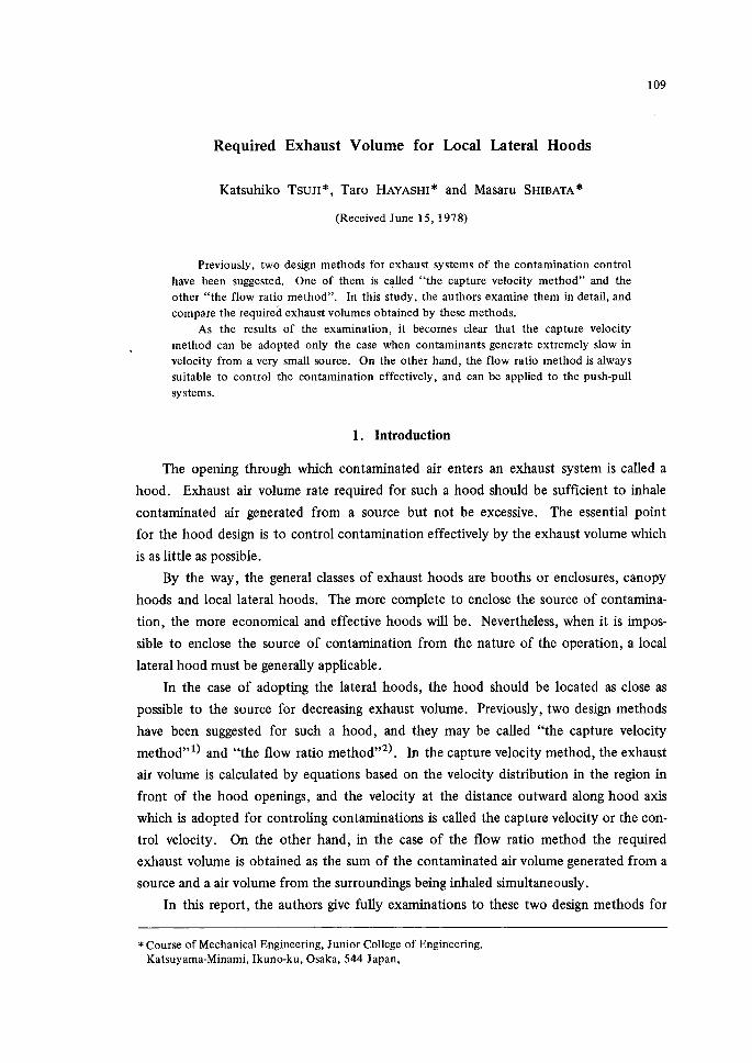
112 Katsuhiko TSUJI, Taro HAYASHI and Masaru SHIBATA
of the unfianged opening and the fianged opening lying on a large flat surface, such as
benches or fioor, does only 50%.
In the capture velocity method, the following disadvatitages may be pointed out.
1) To decide the most suitable hood shapes and sizes to the given source of contami-
nants is very difficult.
2) The capture velocity must be decided after general consideration to the volume or
velocity of contaminated air.
3) The capture velocity selected at X distance is generally diffbrent from the practical
velocity toward the opening at the same point except the volume of contaminated air
being negligible small.
From the above mentioned, in the case of adopting the capture velocity method in
designing the lateral hoods, the hood shapes and the capture velocity should be decided
with many experiences to control the contamination effectively.
Funhermore, the expression that the flange width needs not exceed 6 inchesi) is
questionable as considering the similarity of air flow.
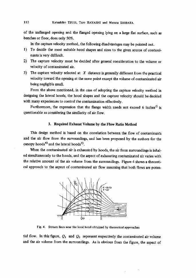
3. Required Exhaust Volume by the Flow Ratio Method
This design method is based on the correlation between the flow of contaminants
and the air flow from the surroundings, and has been proposed by the authors fbr the
canopy hoods4) and the lateral hoods2).
When the contaminated air is exhausted by hoods, the air from surroundings is inhal-
ed simultaneously to the hoods, and the aspect of exhausting contaminated air varies with
the relative amount of the air volume from the surroundings. Figure 4 shows a theoreti-
cal approach to the aspect of contaminated air flow assuming that both flows are poten-
:1
::::,
::::
:::
:::1
:::)
:::
::
::'
:::
lg,i'
' , l t dlJLi
::
::
1
,
,
:
:L
::
:
1
:
1
,
1
:1
xK= 10%l 20%l'
o%II 100'% il200%
l400%
L・ :・ L
:::
xi
l
,
,
:i・
I
,
'
:::
s
'
:
'
1
:
:
J
l
,e)lt,
-11
2::Sl,?gQi
bQ,J
1
Fig 4. Stream lines near the local hood obtained by theoretical approaches
tial flow. In this figure, ei and e2 represent respectively the contaminated air volume
and the air volume from the surroundings. As is obvious from the figure, the aspect of
Required Exhaust VOIume for Loeal Lateral Hbods 113
contaminated air flow varies with the ratio of e2 to ei, and K(=e2/ei) is called
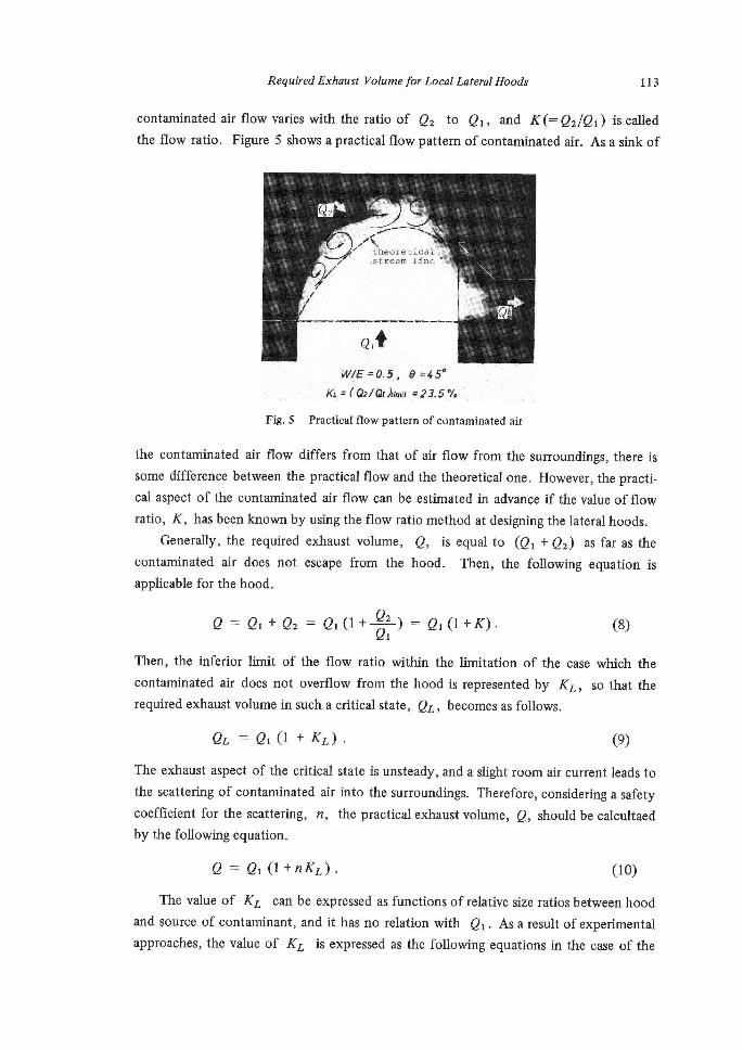
the flow ratio. Figure 5 shows a practical flow pattern of contaminated air. As a sink of
i..;x<W'pt-'"'s-
thteoyeeiti¢en1.i ,ststeenm 1±.nee
Q,t
twff -'-- e.s. e =4se
}Q #r Gilth k.st ---23.S%
Fig. 5 Practical flow pattern of contaminated air
the contarninated air fiow diflfers from that of air flow from the surroundings, there is
some difference between the practical flow and the theoretical one. However, the practi-
cal aspect of the contaminated air flow can be estimated in advance if the value of flow
ratio, K, has been known by using the flow ratio method at designing the lateral hoods.
Generally, the required exhaust volume, e, is equal to (ei+e2) as far as the
contaminated air does not escape from the hood. rlhen, the following equation is
applicable fbr the hood.
e, e == ei+e2 =ei (1+ e, )= ei (1+K)・ (8)
Then, the inferior lmit of the flow ratio within the lmitation of the case which the
contaminated air does not overflow from the hood is represented by KL, so that the
required exhaust volume in such a critical state, eL , becomes as follows.
eL =ei (1+KL). (9)The exhaust aspect of the critical state is unsteady, and a slight room air current leads to
the scattering of contaminated air into the surroundings. Therefore, considering a safiety
coefficient for the scattering, n, the practical exhaust volume, e, shouldbe calcultaed
by the following equation.
e= ei (1 +nKL). (10) The value of KL can be expressed as functions ofrelative sizeratiosbetween hood
and source of contaminant, and it has no relation with ei. Asaresult of experimental
approaches, the value of KL is expressed as the following equations in the case of the
114 Katsuhiko TSUJI, Taro HAYASHI
lateral exhaust hoods2) .
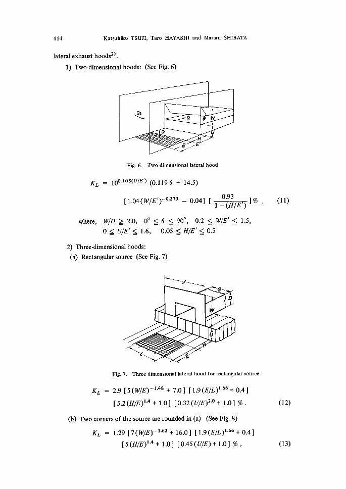
1) Two-dimensional hoods: (See Fig. 6)
and Masaru SHIB2e(rA
Q2 × -Q
a
E
Fig.6. Twodimensionallateralhood
KL : loO・i05(U/E') (o.11ge + 14.s)
O.93 [1.04(milE')-O・273 m o.o4] [ l% 1 - (H/E')
where, wrD ) 2.0, OO ge S 900, O.2 S MLIE'g 1.5,
O :lll U7E' $ 1.6, O.05 g HIE' f$I O.5
2) Three-dimensionalhoods:
(a) Rectangular source (See Fig.7)
'
(11)
`"'
GD'
U
<( e
Fig. 7. Three dimenslonal lateral hood for rectangular source
KL = 2.9 [5(eqIE)-i・`8 +7.o] [1.g(EIL)i・66+o.4]
[5.2 (HIE)i・4 + 1.0] [O.32([7]IE)2・O + 1.o] %.
(b) Two corners ofthe source are roundedin (a) (See Fig. 8)
KL = 1.29 [7(WIE)-i・62 + 16.0] [1.g(,EIL)i・66+o.4]
[s(HIE)i・4 + 1.0] [O.45(Ul[E)+ 1.0] % ,
(12)
(13)
Required Exhaust Vblume for Local Lateral Hbods 115
y`f`'`"
iilS
(
Fig. 8. Three dimensional hood for source with two rounded corners
where, Vi7D 2 2D, O.7 $ MVE S 2.5, O< EllL K 2.0,
O :!{ HIE fS 1.0, OS UIE fll 2.5
As it is clear from eq. (10) that the value of KL is related to the required exhaust
volume, it is very important for designing hoods. Therefore, in the case of designing the
hoods, the shapes of the hood should be decided as the value of KL becomes as small as
possible. For this purpose, the fundamental factors of deciding hood shapes are as
follows from eqs. (1 1), (12) and (13).
(1) The length of U and Hshouldbe decided as small as operation permit,because the
hood must be located as close as possible to the source.
(2) The flange angle should be e = oO.
(3) In principle,the shape ofthe hood and the source ofcontaminants should be slmilar.
(4) The size ofopening should be as MVD ll2.0.
(5) The hood should belocated in the direction as E7L S 1.0.
(6) [he fiange size should be as O.5 g WIE $ 1.0 in the case oftwo dimensional hoods
and as 1.0 S WIE g 2.0 in the case of three dimensional hoods.
In the flow ratio method, the shapes of the hood are decided based on the above
factors, and the required exhaust volume for the hood is calculated by using eq. (10).
However, the volume of contaminants generated from the source remains unknown so
far. There are various knds of contaminant source. In paticular, when an extremely
small amount of harmfu1 article is generated from the contaminated source, it is very
difficult to estimate its volume or velocity. In such a case, the generating velocity should
be estimated at O.2-O.3 m/s because it can be considered that the velocity of room air
current is the same degree.
Then, the value of the safety coefficient for scattering should be usually taken as
n)3.0, but, the value of n being taken to be n=5-le may be desirable when the
room air current must be taken into consideration or the contaminants from the source
are considerably toxic.

116 Katsuhiko TSUJI, Taro HAYASHI and Masaru SH!Bie(TA
4. ComparisonofRequiredExhaustVolume
Now, let us consider the case when a local lateral hood is located beside the given
square source ofcontaminants ofwhich the length ofthe side is E m as shown in Fig.9
and the contaminated air rises with the velocity Vi m/s, in order to compare the
e
w
i-
s
wi
,
-va
,
tv
]s,(
,.,Q
Fig. 9. Lateral hood for equare source
required exhaust volumes obtained by the flow ratio method and the capture velocity
method. The shapes of the hood are decided as shown in the figure based on the flow
ratio method, because in the capture velocity method it is not shown evidently how to
decide the hood shapes.
We shall begin with the estirnasion of exhaust volume based on the capture velocity
method. As can be seen from the figure, distance X is equal to E andhood opening
area, A, is equal to (Ml12)2 in eq. (3), then, the followingequation is obtained.
e = O.5 Vb (10E2 + w2/4)
= O.5 P,b [10+(MillE)2/41 E2. (14)
Frorn the above equation, it is evident that the exhaust volume is dominated directly
by the capture velocity, Vb, which is no relation with the volume generated from the
contaminant source. Therefbre, how to choose the capture velocity for the given source
leads to the decislon ad of the exhaust efficiency of the hood. The amount of con-
taminants flow, ei , is expressed as,
ei= Vi xE2. (1 5)From eqs. (14) and (15), the proportion of the exhaust volume, e, to the contaminants
volumel ei , becomes as the fbilowing equation.
Required E:xhaust Vblume for Local Lateral Hbods 117
ele, =(Vh/V,)[10+(MqE)2 /4]/2 . (16)
Next, we shall consider the exhaust volume based on the fiow ratio method. As the
shapes of the source and the hood are already fixed as shown in Fig. 9, the next relations
are applicable.
UIE = O, HIE =O and E7L = 1.0.
By using eq. (12), the value of KL is expressed as the following equation.
KL =O.067 [5(WIE)-i・48+7.0]. (17)
Then, the exhaust volume becomes as fo11ows from eq. (10).
e/ei = 1+ O.067n[5(mVE)-i・`8+ 7.o]. (ls)
The required exhaust volumes have been obtained respectively as eqs. (16) and (18)
based on two methods of designing the local lateral hoods. From these equations, it
becomes clear that in the capture velocity method e is expressed as a function of
VblVi and MVE represented the size of hood, and that in the fiow ratio method as a
function of MllE and the safety coefficient for scattering, n. However, paying attention
to the exponent of WIE in eqs. (16) and (18), the exhaust volume based on the capture
velocity method shows an exactly opposite tendency to the one based on the flow ratio
method, and the smaller the size ofhood, the less the exhaust volume wil1 require.
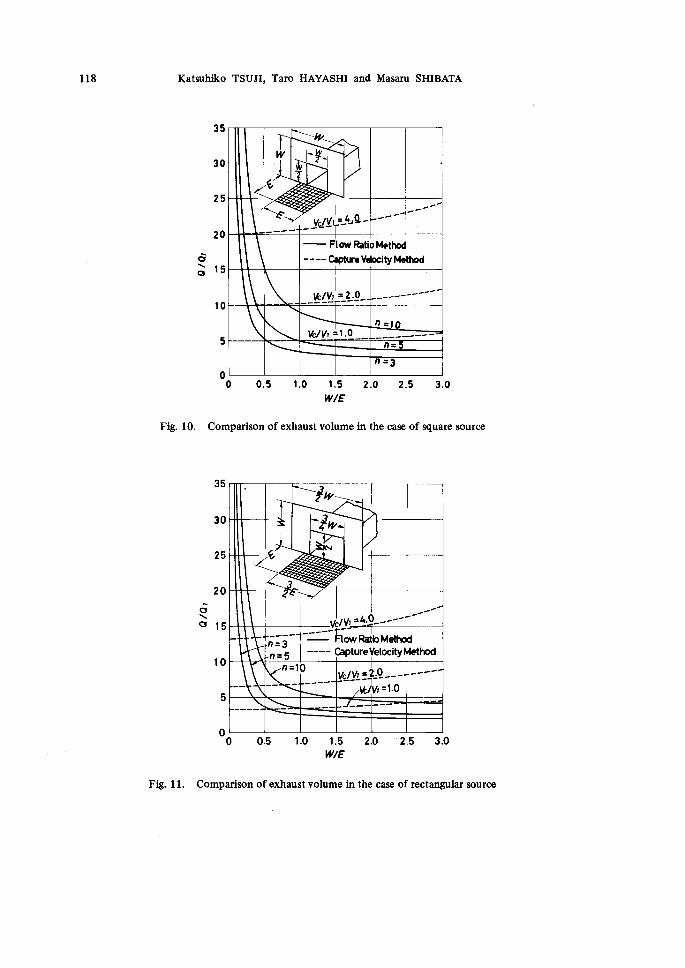
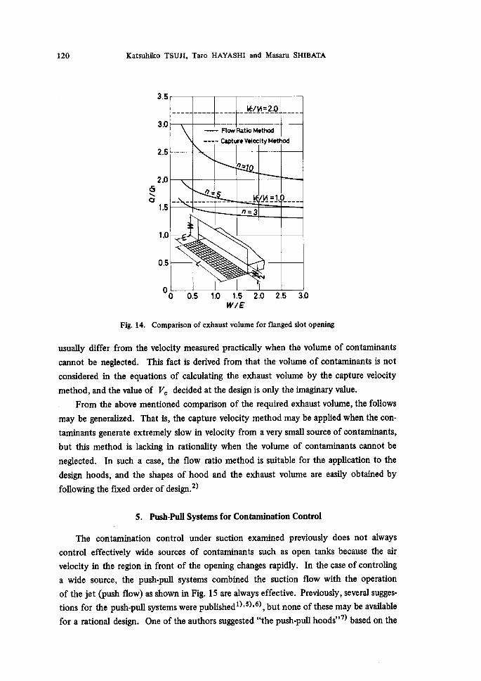
Figu re 10 shows a relation between M,llE and e/ei in order to compare eq. (1 6)
with eq. (18). In the figure, Vb/Vi is taken as aparameter in the case of the capture
velocity method and the safety coefficient, n, is taken in the case of the flow ratio
method. Furthermore, Figs. 11 and 12 show the comparison of the required exhaust
volume when the shapes of the source are changed respectively as L = 3E12 and L =
2E/3, and, the comparisons of the exhaust volume for the slot type openings are shown
in Figs. 13 and 14, which are obtained by the same manner as the rectangular openings.
As pointed out previously, it becomes clear from these figures that the relations
between e/ei and MVE obtained by two methods are quite different. However,
paying attention to the range of Mi7E for the practical use (1.0 f{ M,llE ;SI 2.0 for the
rectangular openings, and O.5 f51 ",7E S 1.0 for the slot type openings)2), the change
of e/ei with M,llE is comparatively small. Furthermore, when the value of Vb/Vi
is taken to be 1.0, the required exhaust volume obtained by the capture velocity method
in the practical use range of M,llE becomes the reasonable exhaust volume corresponding
to n = 5 - 10 obtained by the flow ratio method. From the above mentioned, great
care should be taken about the decision of the capture velocity for calculating the
exhaust volume by using the capture velocity method.
Moreover, it should be noted that the capture velocity decided at a hood design is
118 Katsuhiko TSUJI, Taro HAYASHI and Masaru SHIBATA
Fig. 10.
diNe
35
30
25
2e
15
10
5
o O O.5 1.0, 1.5 2.0 2.5 3.0 WIE
Comparison of exhaust volume in the case of square source
NltFYI
<g
s--.-
1.-vg/y,=.-4Jg-
'---
---t
FtowRatioMettxrc1
----- CaptureVlelocityMethod
ve/v,=2・9.------
..----
-.--- '
WVi=1.0--
n.-.1
------p -.--n=
n=3
Fig. 11.
35
30
25
20 -aNe 15
10
5
o O O.5 1.0 1.5 2.0 '2.5 3.0 wrE
Comparison of exhaust volume in the case of rectangular source
. ]ty
stv
th
1
>1g<g
?℃
ve/V,--4.0 .---.-'
pttt
' --..-n=3n=5
--;:-::'Pr6JR..M ee・,od
CaptureVetocityMethod
n=10 ve1V,=2.0.....-. ---..
- -------- - -'1"ve/V,=1.0
- -

Required E:xhaust Vblbeme for Local Lateral Hbods 119
Fig. 12.
35
30
25
20
di xQ 15
10
5
o O O.5 1.0 1.5 2.0 2.5 3.0 WIE
Comparison of exhaust volume in the case of rectangular source
-------'---p
>3Zth.-vhIv.,;-4..・9-
''`"t
l)
sF
ve/v,-.--..- =2.0---" ..--.-
--- ---d
n=1
WVI= 1.0----------
---n- --- -- n=5=3
FtowRatioMethod
---- CaptureVetocityMethod
Fig. 13.
6
5
4
di 3
Ne 2
1
o O O.5 1.0 1.5 2.0 Wts
Comparison of exhaust volume for unflanged slot opening
----- --ve1va=2.0"-------
------
¥O"10-----
E
-----WV,=1.0
-----n=5n=3
---
FtowRatiotvlethod
-CaptureVetocityMethod
120 Katsuhiko TSUJI, Taro HAYASHI and Masaru SHIBATtA
GNcr
3.5
3.0
2.5
20
1.5
1,O
O.5
Oo O.5 1.0 1.5 2.0 2.5 30
WIE
Fig. 14. Comparison of exhaust volume for fianged slot opening
usually differ from the velocity measured practically when the volume of contarninants
cannot be neglected. This fact is derived from that the volume of contaminants is not
considered in the equations of calculating the exhaust volume by the capture velocity
method, and the value of Vb decided at the design is only the lmaginary value.
From the above rnentioned comparison of the required exhaust volume, the follows
may be generalized. That is, the capture velocity method may be applied when the con-
taminants generate extremely slow in velocity from a very small source ofcontaminants,
but this method is lackmg in rationality when the volume of contaminants cannot be
neglected. In such a case, the flow ratio method is suitable fbr the application to the
design hoods, and the shapes of hood and the exhaust volume are easily obtained by
following the fixed order of design.2)
ve!li=2.0-- ---- ----
-FtowRatioMethod
----p CaptureVelocityMethod
htl
oti 5 vaZva=1.0-- ------ ----
n=3
gxxi}illilll
5. Push-Pul1SystemsforContaminationControl
The contamination control under suction examined previousty does not always
control effectively wide sources of contarninants such as open tanks because the air
velocity in the region in front ・of the opening changes rapidly. In the case ofcontrolmg
a wide source, the push-pull systems combined the suction flow with the operation
of the jet (push flow) as shown in Fig. 15 are always effective. Previously, several sugges-
tions for the push-pul1 systems were publishedi)'5)'6) , but none of these may be available
for a rational design. One of the authors suggested "the push-pul1 hoods"7) based on the

Required Exhaust Vblume for Local Lateral Hoods 121
<o
-Vp
aP e
/.rQ/va/'
E
Fig. 15. Push-pull system
fiow ratio method and we claim that it has excellent rationality.
The exhaust volume, e, m,ust need the air volume to inhale all volume ofthe push
flow, ep, blown from the opening, because the push flow mixes with the contaminants
and the air from the surroundings. Therfore, the required exhaust volume is expressed
as the following equations by the experimental approaches.
e= e, (1 +nKB), (19)where, KB = s.s ( -ill-)i・i [o.46 ( lll- )- i・i + o. i3 ] [s.s ( ;i':; )i・4 (.flm)o・2s+ i ] , (2o)
n == 1.0 - 1.5 : safety coefficient for scattering.
As can be seen from the above equations, the exhaust volume, e, is related to the blown
air volume, ep, the velocity ratio, ViIVb, and the relative size ratios ofthe apparatus.
Then, when the conditions of the contaminant source are known, we can obtain the
optimum condition for the blowing side.
Using air volume ei and ep, the velocity ratio becomes as fbllows.
V,IVb == (e,/e,)(nyE). (21)Substituting the above equation into eq. (20), the fbllowing equation is obtained.
KB = s・s (-ill-)i・i [o.46(-lill-)-i・i+o.i3] [s.s(3,')i・4 (-ill-)"i・is+ i]. (22)
The exponent of E)CP in the last term of the above equation is approximately close to
-1.1, and substituting eq. (22) into eq. (19), the required exhaust volume becomes as
the following equation in the case of n = 1 .0.
C= e, [1 +(g,')i・4 I 1.47 (X 7)-i・i+o.41sI + (o.2s3 (X)-i・i+o.o72(S)i・il].
(23)
Then, the value ep which satisfies ae/Oep = O becomes the optimum blowing volume,
and from this relation the optimum blowing velocity is obtained as shown in Fig. 16.

122 Katsuhiko TSUJI, Taro HAYASHI and Masaru SHIBiegTA
s"
3.5
3.0
2.5
2.0
t.5
1.0
O.5
oo
E/P=3O
E/P
EIP=fO
=15
E/Pts
Twvp av
a
E
O.3 O.6 O.9 1.2 1.5
WIE
Ftg. 16. Relation between optimum blowing velocity ratio and relative
sizes of hood
diNe
3.5
3.0
2.5
2.0
1.5
1.0
O.5
o
NN
NN
x
NN
N
N
NN
N
s
PuShPu!t Syistems
N NNN S.Ns
Nsh--
------ E,chaust Stot Hoods
N SSh-E7P=30EveP=15E;tP=10 7VO=5
.Rf.1.Q.
.-n.t-5--.-
n=
ee,austsku
n=
roi!gx
--1----
al E
a
pusrvPutt '
u
---Tiol--
wa
o O.3 O.6 O.9 1.2 1.5
wrE
Fig. 17. Comparison of exhaust volume required for push-pull systems
and slot openings
Next, let us compare the required exhaust volume fbr the push-pul1 system with the
one fbr the slot type lateral hood. Figure 17 shows an example Qf the comparison of the
exhaust volume based on the flow ratio method. In the slot hood, the safety coefficient
for scattering is taken as n = 3, 5 and 10, and in the push-pull svstem. the size ofblow
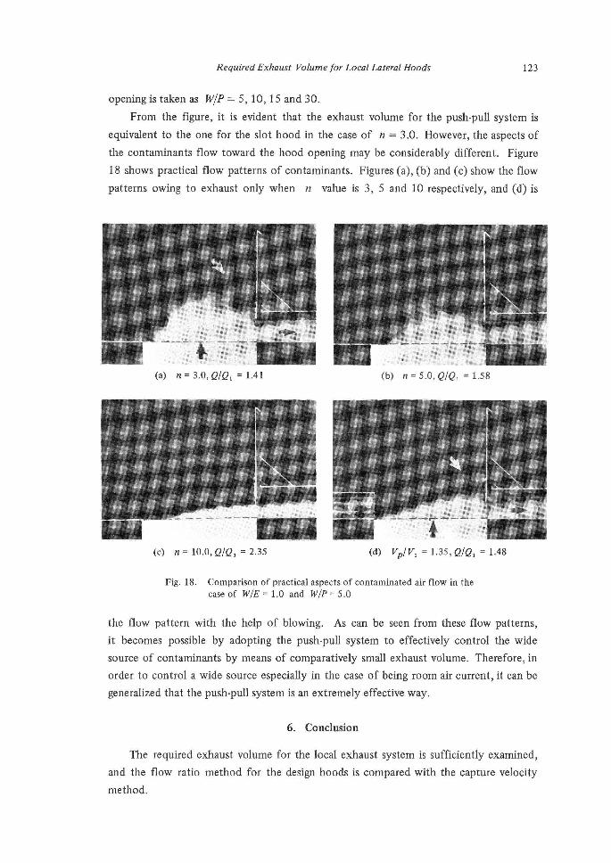
Required Elxhaust Vt) lume for Local Lateral Hbods 123
opening is taken as W/P == 5, 10, 15 and 30.
From the figure, it is evident that the exhaust volume for the push-pull system is
equivalent to the one for the slot hood in the case of n == 3.0. However, the aspects of
the contaminants flow toward the hood opening may be considerably different. Figure
18 shows practical flow patterns of contaminants. Figures (a), (b) and (c) show the flow
patterns owing to exhaust only when n value is 3, 5 and 10 respectively, and (d) is
asdw
(a) n = 3.0, e/e, =
um rw pm
1.41
mla ma- rm ept -an
t. t..
(b) n= s.o, ele, = 1.58
(c) n=10.0,e/e,=2.35 (d) Vb/V,= ,C/Q,=1.48
Fig. 18. Comparison of praetical aspects of contaminated air flow in the
caseof UilE=1.0 and WIP=5.0
the flow pattern with the help of blowing. As can be seen from these flow patterns,
it becomes possible by adopting the push-pull system to eflflectively control the wide
source of contaminants by means of comparatively small exhaust volume. Therefore, in
order to control a wide source especially in the case of being room air current, it can be
generalized that the push-pull system is an extremely effective way.
as1.35
The
and the
rnethod.
6. Conclusion
required exhaust volume for the local exhaust system is sufficiently examined,
flow ratio method for the design hoods is compared with the capture velocity
124 Katsuhiko TSUJI, Taro HAYASHI and Masaru SHIBArrA
The capture velocity method is eflfective so far as the generating velocity of con-
taminants can be negligible small. On the other hand, the flow ratio method has an
excellent rationality fbr designing of exhaust hoods and can be applied to the push-pull
systems.
References
1) A.C.G.I.H., Industrial Ventilation, 8th Ed., p. 4-1, A.C.G.I.H., Lansing, (1964).
2) T. Hayashi et al., Tr. SHASE Japan, 10, 33 (1972).
3) J. M. Dalla Valle, Exhast Hoods, p. 8, Industrial Press, New York, (1952).
4) T. Hayashi et al., Tr. SHASE Japan, 7, 27 (1972).
5) J. L. Alden, Design of Industrial Exhaust Systems, p. 55, Industrial Press, New York, (1959).
6) W. C. L. Hemeon, Prant and Process Ventilation, 2nd Ed., p. 197, Industrial Press, New York,
(1963).7) T. Hayashi, J. SHASE Japan,51, 367 (1977).