title of presentation (type size=32, can accommodate up to ... · session 13014 san 101 . 1 . mike...
TRANSCRIPT

Session 13014
SAN 101
1
Mike Blair – Cisco – [email protected] David Lytle – Brocade – [email protected]
Introduction to Storage Technologies SAN (Storage Area Networking) and
a little FICON (FIber CONnection)
© 2012-2013 Brocade & Cisco- For San Francisco's Spring SHARE 2013 Attendees
QR Code

Notes as part of the online handouts
I have saved the PDF files for my presentations in such a way that all of the audience notes are available as you read the PDF file that you download. If there is a little balloon icon in the upper left hand corner of the slide then take your cursor and put it over the balloon and you will see the notes that I have made concerning the slide that you are viewing. This will usually give you more information than just what the slide contains. I hope this helps in your educational efforts!
2 © 2012-2013 Brocade & Cisco- For San Francisco's Spring SHARE 2013 Attendees

Agenda for Session 13014
Session 13014 Part 1 – 11:00am – 12:00pm • Types and Components of Storage • Let’s talk Fibre Channel • FC Buffer Credits • Fabric Routing / Virtual Fabrics / Partitioning • Security / Zoning Session 13014 Part 2 – 3:00pm – 4:00pm • History • Terminology, Connectors, Cables, and Wavelengths • Addressing in FICON • ESCON Status, zHPF and NPIV • Buffer Credits, CUP, RMF, BC/DR Solutions
3 © 2012-2013 Brocade & Cisco- For San Francisco's Spring SHARE 2013 Attendees

Agenda for Session 13014
Session 13014 • Types and Components of Storage • Let’s talk Fibre Channel • FC Buffer Credits • Fabric Routing / Virtual Fabrics / Partitioning • Security / Zoning
4 © 2012-2013 Brocade & Cisco- For San Francisco's Spring SHARE 2013 Attendees

5
Multiple Infrastructure Vendors (eg. Brocade & Cisco) Several components required to build a SAN • Servers with Host Bus Adapters (HBAs) • Mainframes with FICON Express Channels • Storage systems
• RAID (Redundant Array of Independent/Inexpensive Disks) • JBOD (Just A bunch of Disks) • Tape • VTS/VSM (Virtual Tape)
• Fibre Channel / FICON Switches or Directors • Ethernet Switches (iSCSI / FCoE) • SAN management software
Storage Network Components
© 2012-2013 Brocade & Cisco- For San Francisco's Spring SHARE 2013 Attendees

Direct Attached Storage • Direct Attached Storage (DAS)
• Storage is captive ‘behind’ the server, limited mobility
• Limited scalability due to limited devices
• No storage sharing possible
• Costly to scale
• Management can be complex
• Often cannot take full advantage of the technology
6 © 2012-2013 Brocade & Cisco- For San Francisco's Spring SHARE 2013 Attendees
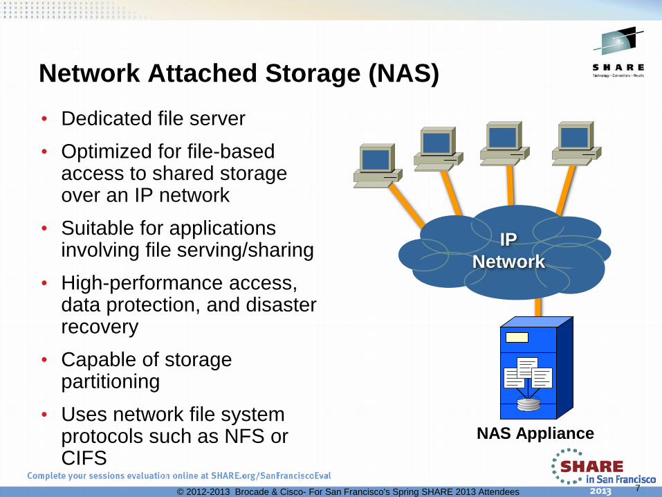
Network Attached Storage (NAS) • Dedicated file server • Optimized for file-based
access to shared storage over an IP network
• Suitable for applications involving file serving/sharing
• High-performance access, data protection, and disaster recovery
• Capable of storage partitioning
• Uses network file system protocols such as NFS or CIFS
NAS Appliance
IP Network
7 © 2012-2013 Brocade & Cisco- For San Francisco's Spring SHARE 2013 Attendees

8
Storage Area Network (SAN)
• Storage is accessed Block-level via SCSI/FICON and can be in a switched environment
• High performance interconnect providing high I/O throughput
• Lower TCO relative to direct attached storage, storage can be shared
• Have to consider Vendor Interoperability / Qualifications
• More Complex management due to size/scale
FICON or Storage Area Network (SAN)
Database/App Servers
Block Storage Devices
FC/FICON SAN
Separation of Storage from the Server Clients
LAN
© 2012-2013 Brocade & Cisco- For San Francisco's Spring SHARE 2013 Attendees

• Light wavelengths in fiber are expressed in nanometers
• Speed of light (C) is about 3 x 10⁸ microseconds (μsec) in a vacuum
• In fibre cable it is about 2/3rds of C or 2 x 10⁸ μsec
• Speed of light in fiber cable is slower than the speed of light in a vacuum so: Light travels at ~5 nanoseconds per
meter (3.3 ft) of distance in glass A rough rule of thumb is 18 inches (45.72
millimeter) per nanosecond It takes about 5 μsec to travel one
kilometer (.621 of a mile) in FC cable It takes about 5 milliseconds to travel
1,000 km (621.4 miles) in FC cable
FC Storage Networking Terminology Light and Fibre Channel
Latency Considerations: • Switch is about 2.1 μsec, P-t-P • Light is about 5 μsec/Km • Inadequate BCs = more latency
© 2012-2013 Brocade & Cisco- For San Francisco's Spring SHARE 2013 Attendees

• Multimode fiber is used for numerous frequencies which are all short-wave frequencies (62.5, 50 micron) of laser light: Always used with short wave optics (transceivers) Used for local distance connectivity (~33-1,640 feet...or...10-500 meters)
• Single-mode fiber has a smaller core that allows only one frequency of light (9 micron) which is long-wave laser light: Always used with long wave optics (transceivers) This is used for longer distance connectivity (up to 15.5 miles or 25 km)
• Optical power budgets, or link loss budgets, measured in decibels (dBs), are used to manage optical signal loss.
FC Storage Networking Terminology Fiber Channel Links
10 © 2012-2013 Brocade & Cisco- For San Francisco's Spring SHARE 2013 Attendees

• Fiber Optic cables transmit a digital signal via pulses of light through a very thin strand of glass. Fiber strands (the core of the fiber optic cable) are extremely thin, no thicker than a human hair. The core is surrounded by a cladding which reflects the light back into the core and eliminates light from escaping the cable.
• A "mode" in Fiber Optic cable refers to the path in which light travels. Multimode cables have a larger core diameter than that of singlemode cables.
• Multimode fiber is available in two sizes, 50 micron and 62.5 micron. Singlemode fiber is available in a core diameter of 9 microns (actually 8.3 microns).
FC Storage Networking Terminology Fiber Channel Links
11 © 2012-2013 Brocade & Cisco- For San Francisco's Spring SHARE 2013 Attendees

• Photo of Modal dispersion • As you can see, a beam of light travels from side to side as it travels
from one end of the cable to the other. This is how fibre optics can transmit data across long distances while not confined to being straight line of sight paths.
FC Storage Networking Terminology Fiber Channel Links
Light enters the cable
Light carries through the cable with a little dispersion
Without the cable light dispersion happens quickly
12 © 2012-2013 Brocade & Cisco- For San Francisco's Spring SHARE 2013 Attendees
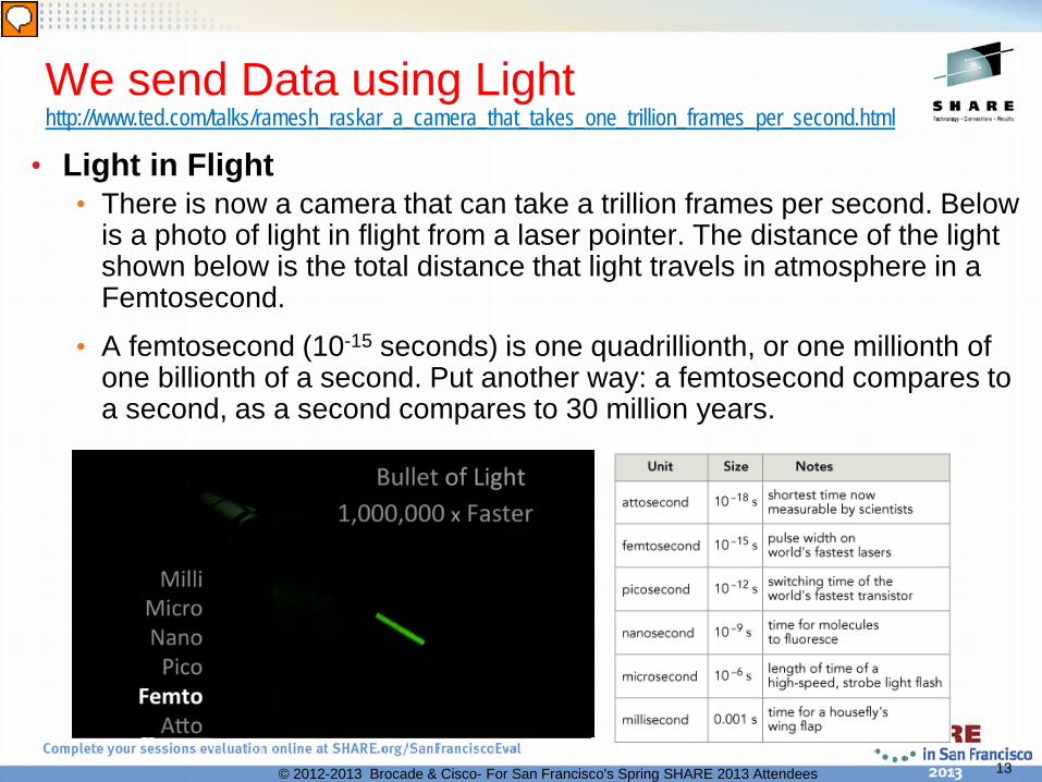
• Light in Flight • There is now a camera that can take a trillion frames per second. Below
is a photo of light in flight from a laser pointer. The distance of the light shown below is the total distance that light travels in atmosphere in a Femtosecond.
• A femtosecond (10-15 seconds) is one quadrillionth, or one millionth of one billionth of a second. Put another way: a femtosecond compares to a second, as a second compares to 30 million years.
We send Data using Light http://www.ted.com/talks/ramesh_raskar_a_camera_that_takes_one_trillion_frames_per_second.html
13 © 2012-2013 Brocade & Cisco- For San Francisco's Spring SHARE 2013 Attendees

• A link consists of • 2 unidirectional “fibers”
transmitting in opposite directions
• May be either: Optical fiber or Copper
• Transmitters may be:
• Long wave laser There can be multiple
distances for these – ie. 4km/10km
• Short wave laser • LED • Electrical
14
SAN Terminology -- Fiber Channel Link
Switched-FCP and Switched-FICON Director Chassis’s Run At:
Brocade Cisco 2Gbps 2Gbps 4Gbps 4Gbps 8Gbps 8Gbps
16Gbps
© 2012-2013 Brocade & Cisco- For San Francisco's Spring SHARE 2013 Attendees

• HSSDC2 Copper Connector • Fits in SFP Media Slots • Smaller than HSSDC
LC Optical Connector – Standard on 2-8Gbps Switches – Most widely used connector
Cable Shown as Bonded Duplex
SC Optical Connector – Standard on 1 Gbps Switches – Little used any longer
Cable Shown as Bonded Duplex
HSSDC Copper Connector – Smaller than older connectors – Easier to insert/remove
OP
TIC
AL
CO
PP
ER
15
SAN Terminology -- Fiber Channel Link
© 2012-2013 Brocade & Cisco- For San Francisco's Spring SHARE 2013 Attendees

Device Ports • N_Port – Node Port, a Fabric device directly attached
Switch Ports • G_Port – Generic Port, a port waiting to become an E or F_Port • F_Port – Fabric Port, a port to which an N_Port attaches • E_Port – Expansion port used for inter-switch links
System z
N_Port N_Port F_Port
F_Port ? G_Port
E_Port
E_Port
Open Systems
16
SAN Terminology -- Fibre Channel
© 2012-2013 Brocade & Cisco- For San Francisco's Spring SHARE 2013 Attendees

• Interconnection between switches is called the Inter-Switch Link (ISL) or in FICON a Cascaded Link (uses Expansion Ports – E_Port) • E_Port to E_Port (aka ISL) • For FICON, a 10Gbps link can ONLY BE a cascaded link (ISL)
• Allows switches to be connected together to create a multi-switch Fabric
• Supports all classes of service • Class 1, 2, 3, and a special Class F
• The FC Standard permits consecutive frames of a sequence to be routed over different, parallel ISL links for maximum throughput
E E 17
SAN Terminology -- Fibre Channel
© 2012-2013 Brocade & Cisco- For San Francisco's Spring SHARE 2013 Attendees

Agenda for Session 13014
Session 13014 • Types and Components of Storage • Let’s talk Fibre Channel (MIKE) • FC Buffer Credits • Fabric Routing / Virtual Fabrics / Partitioning • Security / Zoning
18 © 2012-2013 Brocade & Cisco- For San Francisco's Spring SHARE 2013 Attendees

Fibre Channel Protocol
Fibre Channel (FC) provides high speed transport for Upper level (ie. FICON or SCSI) payloads
• FC is the “protocol” for a Storage Network – attributes are: • Highly Scale - Addressing for up to 16 million nodes • Various Switched Topologies • High Speeds - 100, 200, 400, 800 or 1600 MBps • 8Gb, 10Gb or 16Gb ISLs can be deployed • Segments of up to 100 Km between switches • Support for multiple protocols like FICON and OPEN (SAN) • Support for Security via Zoning and Prohibit/Allow Matrix
19 © 2012-2013 Brocade & Cisco- For San Francisco's Spring SHARE 2013 Attendees

Fibre Channel Acceptance • In September 2011
Gartner, Inc. analysts made an interesting update to their “IT Market Clock” series specifically for the Storage Technology market.
• What they show is that Fibre Channel Networking has just reached the Zenith of Industrialization of the technology lifecycle.
20 © 2012-2013 Brocade & Cisco- For San Francisco's Spring SHARE 2013 Attendees

The Fibre Channel Protocol
FC-3
Common Services
Login Server, Name Server, Alias Server
Framing Protocol / Flow Control FC-2 Data packaging, Class of service, Port Login / logout, Flow control...
FC-1 Transmission Protocol - Encode / Decode
Serial Interface (one bit after another) Frame Transfer (up to 2048 byte payload) 8b/10b or 64b/66b data encode / decode
FC-0 Interface/Media – The Physical Characteristics Cables, Connectors, Transmitters & Receivers...
• FCP and FICON are just a part of the upper layer (FC-4) protocol
• They are compatible with existing lower layers in the protocol stack
FC-4 Protocol Mapping Layer Upper Level Protocol (ULP) FCP/FICON/HIPPI/Multi-media, etc.
21 © 2012-2013 Brocade & Cisco- For San Francisco's Spring SHARE 2013 Attendees
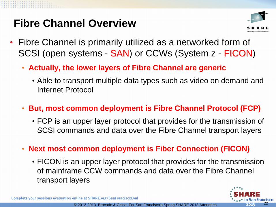
Fibre Channel Overview • Fibre Channel is primarily utilized as a networked form of
SCSI (open systems - SAN) or CCWs (System z - FICON) • Actually, the lower layers of Fibre Channel are generic
• Able to transport multiple data types such as video on demand and Internet Protocol
• But, most common deployment is Fibre Channel Protocol (FCP) • FCP is an upper layer protocol that provides for the transmission of
SCSI commands and data over the Fibre Channel transport layers
• Next most common deployment is Fiber Connection (FICON) • FICON is an upper layer protocol that provides for the transmission
of mainframe CCW commands and data over the Fibre Channel transport layers
22 © 2012-2013 Brocade & Cisco- For San Francisco's Spring SHARE 2013 Attendees

World Wide Names
• Each switch element is assigned a 64 bit WWN at time of manufacture
• Each switch port is assigned a 64 bit WWPN at the time manufacture
• During Fabric Logon (FLOGI) the switch identifies the WWN in the service parameters of the accept frame
• After FLOGI/PLOGI the WWNs and WWPNs have been mapped to Fibre Channel Identification (FCID) addressing
These Address Assignments Can then Correlate Each Fabric Port with Switch Routing and the Fiber
Channel ID (FCID)
23 © 2012-2013 Brocade & Cisco- For San Francisco's Spring SHARE 2013 Attendees

B50600
Domain ID in Hex (Switch address) Port Address In Hex
(Path to device)
NPIV or Vendor address (ALPA)
Fabric Addressing
Fibre Channel ID (FCID) Addressing
8 bits – 1 byte 8 bits – 1 byte 8 bits – 1 byte DOMAIN
ID of Switch to which Storage is attached
AREA Port on switch to which
Storage is attached
PORT or 00 Virtual Channel Path
Port Address for Linux
• The 24 bit FCID address is partitioned into 3 fields: • Port (various uses); Area (connects to a device); Domain (which switch to find)
• This address partitioning helps speed up routing • Switch element assigns the address to N_Ports • Address portioning is transparent to N_Ports
Open Systems – Device Address System z – Vendor Code / NPIV
24 © 2012-2013 Brocade & Cisco- For San Francisco's Spring SHARE 2013 Attendees

Fibre Channel Frame Format • All FC-SBx frames follow the general frame format as shown below • IDLE or ARB(ff) primitive characters are used during FLOGI link
synchronization (these characters precede and follow each frame) • IDLE or ARB primitives are ‘Ordered Sets’ used for basic signaling (1, 2, 4
and 10Gbps use IDLEs between frames while 8Gb and 16Gbps use Idles or ARBs)
• 8b/10b data encoding is used for 1, 2, 4 and 8Gbps frames – 20% overhead
• 64b/66b data encoding is used for 10Gbps and 16Gbps frames – 3% overhead
0-2048 for FICON
25 © 2012-2013 Brocade & Cisco- For San Francisco's Spring SHARE 2013 Attendees

Storage Networking Topology Dual Star (non-cascaded for FICON)
• Provides an opportunity to deploy fabrics to meet five-9’s of availability • Still must insure <=5 min/annual fabric downtime
26
Application A
Application B
Application C Shared Storage
Resources
Protocol Intermixed Fabrics
© 2012-2013 Brocade & Cisco- For San Francisco's Spring SHARE 2013 Attendees

Application C
Storage Resources
Typical SAN Topology Core-to-Edge (distributed systems only)
• Requires multi-hop so it is not currently supported for FICON due to IBM Qualification
27
Application B
SAN Fabrics
Shared Storage Resources
© 2012-2013 Brocade & Cisco- For San Francisco's Spring SHARE 2013 Attendees
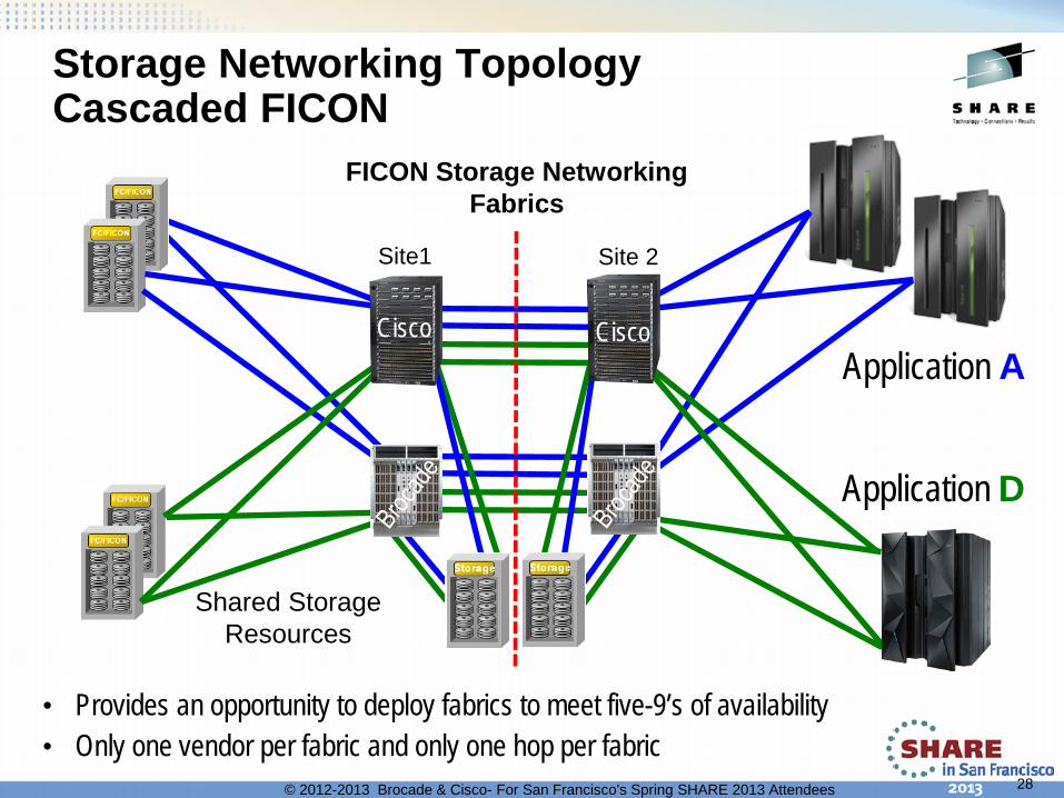
Storage Networking Topology Cascaded FICON
• Provides an opportunity to deploy fabrics to meet five-9’s of availability • Only one vendor per fabric and only one hop per fabric
28
Application A
Application D
Shared Storage Resources
FICON Storage Networking Fabrics
Site 2 Site1
Cisco Cisco
© 2012-2013 Brocade & Cisco- For San Francisco's Spring SHARE 2013 Attendees

Storage Networking Topology Cascaded FICON and FCP
• Provides an opportunity to deploy fabrics to meet five-9’s of availability • Only one vendor per fabric and Only one hop
29
Application A
Application D
Shared Storage Resources
Protocol Intermixed Fabrics
Cisco Cisco
© 2012-2013 Brocade & Cisco- For San Francisco's Spring SHARE 2013 Attendees

30
ISL Aggregation
• Increases bandwidth and availability • Simplifies Topology • Usually some load balancing • Interfaces can both be added and
removed in a non-disruptive manner in production environments
• Preserves FC guarantee of in-order delivery (IOD)
Port Aggregation Is Used to Create a Single Logical ISL from multiple Physical ISLs Different names depending upon the vendor Brocade = Trunking Cisco = Port Channel
© 2012-2013 Brocade & Cisco- For San Francisco's Spring SHARE 2013 Attendees
4 Link trunked groupings
Cisco Brocade

Agenda for Session 13014
Session 13014 • Types and Components of Storage • Let’s talk Fibre Channel • FC Buffer Credits • Fabric Routing / Virtual Fabrics / Partitioning • Security / Zoning
31 © 2012-2013 Brocade & Cisco- For San Francisco's Spring SHARE 2013 Attendees

FC Buffer Credits and Flow Control
32
Storage
16 40
202 202
200 16
Fiber Cable Strand 1 Strand 2
I can receive 40 frames (buffer credits) but after that you will have to stop
sending frames until I acknowledge some or all of them.
That is fine – I can only receive 16 frames myself. This is OK since we are only a few
feet/meters apart anyway.
We are long distance ISL links and therefore we need extra buffer credits in order to keep the link fully utilized.
Like most modern DASD and Tape storage, I have a set number of frames that I can handle and I
will let you know what the maximum BC limit will be.
Director or Switch
© 2012-2013 Brocade & Cisco- For San Francisco's Spring SHARE 2013 Attendees

33
FC Buffer Credits and Flow Control
FC
• BB_Credits are the “admission control” mechanism in FC to ensure that FC switches don’t run out of buffers (FC Switches cannot drop frames)
• For Devices operating at FC Class 3 (most devices), Buffer Credits are determined at login.
• BB_Credits are the only flow-control mechanism for FC Class 3.
available BB_Credits
Frame towards Disk shelf Return BB_Credit token
16 15 available
BB_Credits
16 15
© 2012-2013 Brocade & Cisco- For San Francisco's Spring SHARE 2013 Attendees

34
Buffer Credits (BB_Credits): Working Clean
FC
Disk shelf capable of sustaining
8 Gbps data rate
Physical Tape capable of sustaining
4 Gbps data rate
Frame towards Tape Return BB_Credit token
Frame towards Disk shelf
/
Available BB_Credits
16/16
Available BB_Credits
Available BB_Credits 16/16
13/16 12/16 14/16 15/16 10/16 9/16 11/16
13/16 12/16 14/16 15/16 11/16
8/16 7/16
16/16 13/16 12/16 14/16 15/16 11/16
Buffer Credits are a “Flow Control” mechanism to assure that frames are sent correctly In an ideal FC network, there is no blocking in any device connected to the fabric. (All devices can process frames at the same rate and negotiate equal levels of BB_Credits)
© 2012-2013 Brocade & Cisco- For San Francisco's Spring SHARE 2013 Attendees

35
32 Km
32 Km
1 Gbps FC
2 Gbps FC ~1 km per Frame
~2 km per Frame
FC BB_Credits and Distance
• BB_Credits are used to make sure that data frames do not overrun the receiver
• BB_Credits are used to ensure high link utilization via enough FC frames in flight
• A full (2112 byte) FC frame is approximately 1 km long @ 2 Gbps and approximately .5 km long @ 4 Gbps and approximately .25 km long @ 8 Gbps, etc.
• As distance increases, the BB_Credits needed for high link utilization increase as well
• Shorter frames will require additional BB_Credits to ensure a “full pipe” – and for most FC data it is smaller frames that are sent!
• Insufficient BB_Credits will throttle performance—no data will be transmitted until a frame received acknowledge is returned (R_Rdy)
© 2012-2013 Brocade & Cisco- For San Francisco's Spring SHARE 2013 Attendees

36
Buffer Credits Required By Size of Frame and Link Speed
As distance link speed grows, so does the need for buffer credits!
© 2012-2013 Brocade & Cisco- For San Francisco's Spring SHARE 2013 Attendees

Defining CUP in HCD
If it is a non-cascaded fabric then this example could
have used single byte LINK= addressing rather than
2-byte addressing.
© 2012-2013 Brocade & Cisco- For San Francisco's Spring SHARE 2013 Attendees 37

RMF 74-7 Records • Enabling RMF 74 subtype 7 (RMF 74-7) records yields an RMF report called the
“FICON Director Activity Report”. This is for switches or Directors.
• Data is collected for each RMF interval if FCD is specified in the ERBRMFnn parmlib member …AND… in SYS1.Parmlib the IECIOSnn says FICON STATS=YES. (FCD/NOFCD can also be modified via an operator command)
• The FICON Director Activity Report captures information based on an interval which is set for RMF and tells it when to create this report along with others.
• In essence, the report captures a snapshot of data and the counters based on an time interval, such as 20 minutes. Often, you need to run these reports more than once and change the interval periods for troubleshooting to determine if there is a trend .1
• This RMF report is often overlooked but contains very meaningful data concerning FICON I/O performance - in particular, frame pacing delay
• Frame pacing delay is the only fabric-wide method to indicate a BB_Credit starvation issue on a given port 2
© 2012-2013 Brocade & Cisco- For San Francisco's Spring SHARE 2013 Attendees 38

Agenda for Session 13014
Session 13014 • Types and Components of Storage • Let’s talk Fibre Channel • FC Buffer Credits • Fabric Routing / Virtual Fabrics / Partitioning (MIKE) • Security / Zoning
39 © 2012-2013 Brocade & Cisco- For San Francisco's Spring SHARE 2013 Attendees

Fabric Routing Across ISLs: FSPF • For FSPF a domain ID identifies a single switch
• This limits the max number of switches that can be supported in a Fabric to 239 when FSPF is supported • Each Cisco VSAN is treated as a separate Fabric • Each Brocade non-virtualized chassis is treated as a separate fabric • Each Brocade Virtual Fabric (DCX family) is treated as a separate fabric • Each Brocade Physical Partition (Mi10K) is treated as a separate fabric
• FSPF performs hop-by-hop routing • Each Cisco VSAN runs it’s own FSPF process
• Routing between VSAN’s is done with Inter-VSAN Routing (IVR)
• Brocade will use an FSPF routing process called Dynamic Load Sharing (DLS) if TRUNKING is not used • Old CNT/McDATA devices always use FSPF for initial ISL routing
• FSPF (or DLS) supports hierarchical path selection • Provides the scalable routing tables for large topologies
40 © 2012-2013 Brocade & Cisco- For San Francisco's Spring SHARE 2013 Attendees

Deploying Virtual Fabrics / Virtual SANs • Multiple Virtual SANs in a single hardware entity
• Used to Converge SAN Islands • IETF RFC 4747 • Although it is a Standard – Implementations are different per Vendor
• Brocade – optional configuration • Chassis can be either a physical switch or 1 or more logical
switches (Virtual Fabrics disabled or enabled) • Creating a Logical Switch creates a Virtual Fabric (VF) • Each Logical Switch will have a unique Domain ID
• Cisco – required configuration • Virtual SANs (VSANs) are incorporated into the architecture • Each VSAN will have a unique Domain ID
41 © 2012-2013 Brocade & Cisco- For San Francisco's Spring SHARE 2013 Attendees

SAN
Switch Domain
84
4-slot DCX
Domain 64
FICON
VF1 CUP
Domain 63 DID 73, 74
DCX Family Chassis
FICON Zoning Groups
SAN
Virt
ual F
abric
1 C
UP
SAN
Virt
ual F
abric
2 C
UP
SAN
Virt
ual F
abric
3
SAN
Virt
ual F
abric
4 C
UP
75, 76
All Rights Reserved.
Virtual Fabrics (VF) and Brocade • VF is an OPTIONAL feature on all
of the Brocade DCX family of FICON/SAN Directors and switches
• 48-port blades for FICON can be used only when Virtual Fabrics are enabled on the 8-slot DCX chassis • DCX-4S and the DCX 8510-4
never require the use of VF
• VFs creates new services within each Virtual Fabric • Domain ID • Name Server, etc
• Provides additional isolation of ports within a chassis
• Can provision up to 8 virtual fabrics and up to 4 CUP instances on a physical DCX family chassis
© 2012-2013 Brocade & Cisco- For San Francisco's Spring SHARE 2013 Attendees 42

43
Cisco’s VSANs (Virtual SAN) A way to Partition a Switch or SAN into a Virtual/Logical environment
• Virtual SANs created from larger cost-effective redundant physical fabric
• Reduces wasted ports of the older “island” approach
• Hardware-based isolation
• Statistics can be gathered per VSAN
• Management per VSAN
• Unique Serial Number / CUP per FICON VSAN
• Service and process level Isolation between VSANs
FICON
FICON
FICON FICON
© 2012-2013 Brocade & Cisco- For San Francisco's Spring SHARE 2013 Attendees

Agenda for Session 13014
Session 13014 • Types and Components of Storage • Let’s talk Fibre Channel • FC Buffer Credits • Fabric Routing / Virtual Fabrics / Partitioning • Security / Zoning
44 © 2012-2013 Brocade & Cisco- For San Francisco's Spring SHARE 2013 Attendees

Zoning
• A logical grouping of fabric connected devices within a SAN (or virtual fabric)
• Zoning establishes access control • Devices within a zone can access each
other
• Zoning increases security • Limiting access prevents unauthorized
access
• Zone membership might be configured by: • Port World Wide Name (pWWN)—device • Fabric World Wide Name (fWWN)—fabric • Fibre Channel Identifier (FCID) • Fibre Channel Alias (FC_Alias) • IP address • Domain ID/port number • Interface
VF 3
Physical Topology
VF 2
Disk1
Host2 Disk4
Host1
Disk2 Disk3
Disk6 Disk5
Host4
Host3
ZoneA
ZoneB
ZoneC
ZoneA
ZoneD
45 © 2012-2013 Brocade & Cisco- For San Francisco's Spring SHARE 2013 Attendees

FICON Port Security • Zoning
- Able to be used with FICON (some vendors require it, others don’t) • Single Domain
- Prohibit / Allow Matrix (ala. ESCON like port blocking/unblocking) • Cascaded Configurations
- Access to Cascaded resources controlled from IOCDS - Can also be done with Zoning but most choose not to
You can block or prohibit ports, eg: • 05 is blocked and prohibited on all • 04 can reach 07 and 0C • 07 is prohibited from 0C
46 © 2012-2013 Brocade & Cisco- For San Francisco's Spring SHARE 2013 Attendees
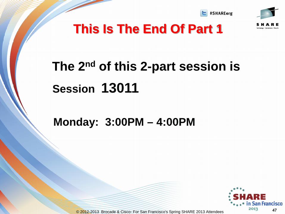
The 2nd of this 2-part session is
Monday: 3:00PM – 4:00PM
Session 13011
47
This Is The End Of Part 1
47 © 2012-2013 Brocade & Cisco- For San Francisco's Spring SHARE 2013 Attendees
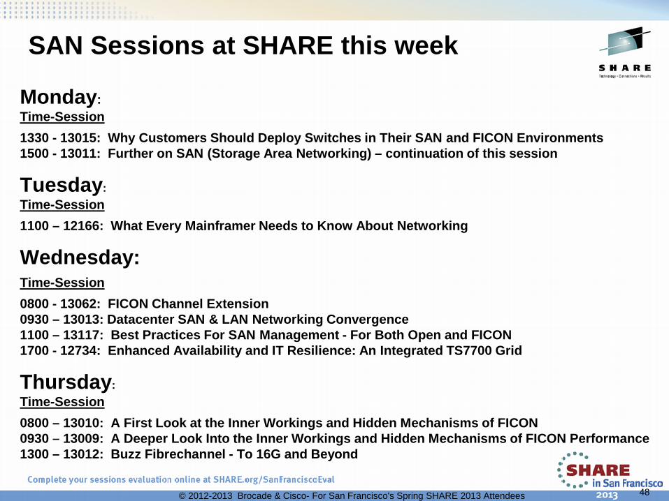
SAN Sessions at SHARE this week
Monday: Time-Session 1330 - 13015: Why Customers Should Deploy Switches in Their SAN and FICON Environments 1500 - 13011: Further on SAN (Storage Area Networking) – continuation of this session
Tuesday: Time-Session 1100 – 12166: What Every Mainframer Needs to Know About Networking
Wednesday: Time-Session 0800 - 13062: FICON Channel Extension 0930 – 13013: Datacenter SAN & LAN Networking Convergence 1100 – 13117: Best Practices For SAN Management - For Both Open and FICON 1700 - 12734: Enhanced Availability and IT Resilience: An Integrated TS7700 Grid
Thursday: Time-Session 0800 – 13010: A First Look at the Inner Workings and Hidden Mechanisms of FICON 0930 – 13009: A Deeper Look Into the Inner Workings and Hidden Mechanisms of FICON Performance 1300 – 13012: Buzz Fibrechannel - To 16G and Beyond
48 © 2012-2013 Brocade & Cisco- For San Francisco's Spring SHARE 2013 Attendees

Mainframe/SAN Resources For You To Use
49
http://community.brocade.com/community/brocadeblogs/mainframe Visit Brocade’s Mainframe Blog Page at:
Visit Brocade’s New Mainframe Communities Page at: http://community.brocade.com/community/forums/products_and_solutions/mainframe_solutions
Visit Cisco’s Storage Networking Page at: http://www.cisco.com/en/US/products/hw/ps4159/index.html
© 2012-2013 Brocade & Cisco- For San Francisco's Spring SHARE 2013 Attendees

Please Fill Out Your Evaluation Forms!!
This was session:
13014
And Please Indicate On Those Forms If There Are Other Presentations You Would Like To See In This Track At SHARE.
50 © 2012-2013 Brocade - For San Francisco Spring SHARE 2013 Attendees
QR Code
Thank You For Attending Today!
5 = “Aw shucks. Thanks!” 4 = “Mighty kind of you!” 3 = “Glad you enjoyed this!” 2 = “A Few Good Nuggets!” 1 = “You Got a nice nap!”