title 128 - department of environmental quality chapter 26
TRANSCRIPT

Title 128 - Department of Environmental Quality Chapter 26 - ORGANIC AIR EMISSION STANDARDS FOR TANKS AND CONTAINERS 001 Applicability.
001.01 The requirements of this Chapter apply to large quantity generators who are subject to Chapter 10 of this Title except as Section 001.02 provides otherwise.
001.02 The requirements of this subpart do not apply to the following waste management units at the facility:
001.02A A container that has a design capacity less than or equal to 0.1 m3.
001.02B A tank in which a generator has stopped adding hazardous waste and the generator has begun implementing or completed closure pursuant to an approved closure plan. 001.02C A waste management unit that is used solely for on-site treatment or storage of hazardous waste that is placed in the unit as a result of implementing remedial activities required under the corrective action authorities of RCRA Sections 3004(u), 3004(v) or 3008(h); CERCLA authorities, or similar Federal authorities.
001.02D A waste management unit that is used solely for the management of radioactive mixed waste in accordance with all applicable regulations under the authority of the Atomic Energy Act and the Nuclear Waste Policy Act.
001.02E A hazardous waste management unit that the generator certifies is equipped with and operating air emission controls in accordance with the requirements of an applicable Clean Air Act regulation codified under 40 CFR part 60, part 61, or part 63, and Title 129 - Nebraska Air Quality Regulations. For the purpose of complying with this paragraph, a tank for which the air emission control includes an enclosure, as opposed to a cover, must be in compliance with the enclosure and control device requirements of Section 005.09, except as provided in Section 003.03E. 001.02F A tank that has a process vent as defined in 40 CFR 264.1031, as incorporated by reference in Chapter 21, 019.
001.03 The requirements of this subpart, except for the recordkeeping requirements specified in Section 009.09 are administratively stayed by EPA for a tank or a container used for the management of hazardous waste generated by organic peroxide manufacturing and its associated laboratory operations when the generator of the unit meets all of the following conditions:
001.03A The generator identifies that the tank or container receives hazardous waste generated by an organic peroxide manufacturing process producing more than one functional family of organic peroxides or multiple organic peroxides within one functional family, that one or more of these organic peroxides could potentially undergo self-accelerating thermal decomposition at or below ambient temperatures, and that organic peroxides are the predominant products manufactured by the process. For the purpose of meeting the conditions of this paragraph, "organic peroxide"

means an organic compound that contains the bivalent -O-O- structure and which may be considered to be a structural derivative of hydrogen peroxide where one or both of the hydrogen atoms has been replaced by an organic radical.
001.03B The generator prepares documentation, in accordance with the requirements of Section 009.09, explaining why an undue safety hazard would be created if air emission controls specified in Sections 005 through 007 are installed and operated on the tanks and containers used at the facility to manage the hazardous waste generated by the organic peroxide manufacturing process or processes meeting the conditions of Section 001.03.
001.03C The generator notifies the Director in writing that hazardous waste generated by an organic peroxide manufacturing process or processes meeting the conditions of Section 001.03A are managed at the facility in tanks or containers meeting the conditions of Section 001.03B. The notification shall state the name and address of the facility, and be signed and dated by an authorized representative of the facility generator.
002 Definitions. As used in this subpart, all terms not defined herein shall have the meaning given to them in the Act and Chapters 1 through 19, and 21 through 23.
002.01 "Average volatile organic concentration" or "average VO concentration" means the mass-weighted average volatile organic concentration of a hazardous waste as determined in accordance with the requirements of Section 004.
002.02 "Closure device" means a cap, hatch, lid, plug, seal, valve, or other type of fitting that blocks an opening in a cover such that when the device is secured in the closed position it prevents or reduces air pollutant emissions to the atmosphere. Closure devices include devices that are detachable from the cover (e.g., a sampling port cap), manually operated (e.g., a hinged access lid or hatch), or automatically operated (e.g., a spring-loaded pressure relief valve).
002.03 "Continuous seal" means a seal that forms a continuous closure that completely covers the space between the edge of the floating roof and the wall of a tank. A continuous seal may be a vapor-mounted seal, liquid-mounted seal, or metallic shoe seal. A continuous seal may be constructed of fastened segments so as to form a continuous seal.
002.04 "Cover" means a device that provides a continuous barrier over the hazardous waste managed in a unit to prevent or reduce air pollutant emissions to the atmosphere. A cover may have openings (such as access hatches, sampling ports, gauge wells) that are necessary for operation, inspection, maintenance, and repair of the unit on which the cover is used. A cover may be a separate piece of equipment which can be detached and removed from the unit or a cover may be formed by structural features permanently integrated into the design of the unit.
002.05 "Enclosure" means a structure that surrounds a tank or container, captures organic vapors emitted from the tank or container, and vents the captured vapors through a closed-vent system to a control device.

002.06 "External floating roof" means a pontoon-type or double-deck type cover that rests on the surface of the material managed in a tank with no fixed roof.
002.07 "Fixed roof" means a cover that is mounted on a unit in a stationary position and does not move with fluctuations in the level of the material managed in the unit.
002.08 "Floating roof" means a cover consisting of a double deck, pontoon single deck, or internal floating cover which rests upon and is supported by the material being contained, and is equipped with a continuous seal.
002.09 "Hard-piping" means pipe or tubing that is manufactured and properly installed in accordance with relevant standards and good engineering practices.
002.10 "In light material service" means the container is used to manage a material for which both of the following conditions apply: The vapor pressure of one or more of the organic constituents in the material is greater than 0.3 kilopascals (kPa) at 20°C; and the total concentration of the pure organic constituents having a vapor pressure greater than 0.3 kPa at 20°C is equal to or greater than 20 percent by weight.
002.11 "Internal floating roof" means a cover that rests or floats on the material surface (but not necessarily in complete contact with it) inside a tank that has a fixed roof.
002.12 "Liquid-mounted seal" means a foam or liquid-filled primary seal mounted in contact with the hazardous waste between the tank wall and the floating roof continuously around the circumference of the tank.
002.13 "Malfunction" means any sudden, infrequent, and not reasonably preventable failure of air pollution control equipment, process equipment, or a process to operate in a normal or usual manner. Failures that are caused in part by poor maintenance or careless operation are not malfunctions.
002.14 "Maximum organic vapor pressure" means the sum of the individual organic constituent partial pressures exerted by the material contained in a tank, at the maximum vapor pressure-causing conditions (i.e., temperature, agitation, pH effects of combining wastes, etc.) reasonably expected to occur in the tank. For the purpose of this Chapter, maximum organic vapor pressure is determined using the procedures specified in Section 004.03.
002.15 "Metallic shoe seal" means a continuous seal that is constructed of metal sheets which are held vertically against the wall of the tank by springs, weighted levers, or other mechanisms and is connected to the floating roof by braces or other means. A flexible coated fabric (envelope) spans the annular space between the metal sheet and the floating roof.
002.16 "No detectable organic emissions" means no escape of organics to the atmosphere as determined using the procedure specified in Section 004.04.
002.17 "Point of waste origination" means as follows:
002.17A When the facility generator is the generator of the hazardous waste, the
point of waste origination means the point where a solid waste produced by a system, process, or waste management unit is determined to be a hazardous waste as defined in Chapters 2 and 3.
002.17B When the facility owner and operator are not the generator of the hazardous waste, point of waste origination means the point where the generator accepts delivery or takes possession of the hazardous waste.
002.18 "Point of waste treatment" means the point where a hazardous waste to be treated in accordance with Section 003.03B exits the treatment process. Any waste determination shall be made before the waste is conveyed, handled, or otherwise managed in a manner that allows the waste to volatilize to the atmosphere.
002.19 "Safety device" means a closure device such as a pressure relief valve, frangible disc, fusible plug, or any other type of device which functions exclusively to prevent physical damage or permanent deformation to a unit or its air emission control equipment by venting gases or vapors directly to the atmosphere during unsafe conditions resulting from an unplanned, accidental, or emergency event. For the purpose of this subpart, a safety device is not used for routine venting of gases or vapors from the vapor headspace underneath a cover such as during filling of the unit or to adjust the pressure in this vapor headspace in response to normal daily diurnal ambient temperature fluctuations. A safety device is designed to remain in a closed position during normal operations and open only when the internal pressure, or another relevant parameter, exceeds the device threshold setting applicable to the air emission control equipment as determined by the generator based on manufacturer recommendations, applicable regulations, fire protection and prevention codes, standard engineering codes and practices, or other requirements for the safe handling of flammable, ignitable, explosive, reactive, or hazardous materials.
002.20 "Single-seal system" means a floating roof having one continuous seal. This seal may be vapor-mounted, liquid-mounted, or a metallic shoe seal.
002.21 "Vapor-mounted seal" means a continuous seal that is mounted such that there is a vapor space between the hazardous waste in the unit and the bottom of the seal.
002.22 "Volatile organic concentration" or "VO concentration" means the fraction by weight of the volatile organic compounds contained in a hazardous waste expressed in terms of parts per million (ppmw) as determined by direct measurement or by knowledge of the waste in accordance with the requirements of 40 CFR 265.1084 of this subpart. For the purpose of determining the VO concentration of a hazardous waste, organic compounds with a Henry's law constant value of at least 0.1 mole-fraction-in-the-gas-phase/mole-fraction-in the liquid-phase (0.1 Y/X) (which can also be expressed as 1.8 x 10⁻⁶ atmospheres/gram-mole/m3) at 25 degrees Celsius must be included. Section 010 of this Chapter presents a list of compounds known to have a Henry's law constant value less than the cutoff level.
002.23 "Waste determination" means performing all applicable procedures in accordance with the requirements of Section 004 to determine whether a hazardous waste meets standards specified in this subpart. Examples of a waste determination include performing the procedures in accordance with the requirements of Section 004 to determine the average VO concentration of a hazardous waste at the point of waste origination; the average VO
concentration of a hazardous waste at the point of waste treatment and comparing the results to the exit concentration limit specified for the process used to treat the hazardous waste; the organic reduction efficiency and the organic biodegradation efficiency for a biological process used to treat a hazardous waste and comparing the results to the applicable standards; or the maximum volatile organic vapor pressure for a hazardous waste in a tank and comparing the results to the applicable standards.
002.24 "Waste stabilization process" means any physical or chemical process used to either reduce the mobility of hazardous constituents in a hazardous waste or eliminate free liquids as determined by Test Method 9095 (Paint Filter Liquids Test) in "Test Methods for Evaluating Solid Waste, Physical/Chemical Methods," EPA Publication No. SW-846, Third Edition, September 1986, as amended by Update I, November 15, 1992 (incorporated by reference-refer to Chapter 1, 003). A waste stabilization process includes mixing the hazardous waste with binders or other materials, and curing the resulting hazardous waste and binder mixture. Other synonymous terms used to refer to this process are "waste fixation" or "waste solidification." This does not include the adding of absorbent materials to the surface of a waste, without mixing, agitation, or subsequent curing, to absorb free liquid.
003 Standards: General.
003.01 This section applies to the management of hazardous waste in tanks and containers subject to this subpart.
003.02 The generator shall control air pollutant emissions from each hazardous waste management unit in accordance with standards specified in Sections 005 through 007, as applicable to the hazardous waste management unit, except as provided for in Section 003.03.
003.03 A tank or container is exempt from standards specified in Section 005 through 007, as applicable, provided that the waste management unit is one of the following:
003.03A A tank or container for which all hazardous waste entering the unit has an average VO concentration at the point of waste origination of less than 500 parts per million by weight (ppmw). The average VO concentration shall be determined using the procedures specified in Section 004.01. The generator shall review and update, as necessary, this determination at least once every 12 months following the date of the initial determination for the hazardous waste streams entering the unit.
003.03B A tank or container for which the organic content of all the hazardous waste entering the waste management unit has been reduced by an organic destruction or removal process that achieves any one of the following conditions:
003.03B1 A process that removes or destroys the organics contained in the hazardous waste to a level such that the average VO concentration of the hazardous waste at the point of waste treatment is less than the exit concentration limit (Ct) established for the process. The average VO concentration of the hazardous waste at the point of waste treatment and the exit concentration limit for the process shall be determined using the
procedures specified in Section 004.02.
003.03B2 A process that removes or destroys the organics contained in the hazardous waste to a level such that the organic reduction efficiency (R) for the process is equal to or greater than 95 percent, and the average VO concentration of the hazardous waste at the point of waste treatment is less than 100 ppmw. The organic reduction efficiency for the process and the average VO concentration of the hazardous waste at the point of waste treatment shall be determined using the procedures specified in Section 004.02.
003.03B3 A process that removes or destroys the organics contained in the hazardous waste to a level such that the actual organic mass removal rate (MR) for the process is equal to or greater than the required organic mass removal rate (RMR) established for the process. The required organic mass removal rate and the actual organic mass removal rate for the process shall be determined using the procedures specified in Section 004.02.
003.03B4 A biological process that destroys or degrades the organics contained in the hazardous waste, such that either of the following conditions is met:
003.03B4(a) The organic reduction efficiency (R) for the process is equal to or greater than 95 percent, and the organic biodegradation efficiency (Rbio) for the process is equal to or greater than 95 percent. The organic reduction efficiency and the organic biodegradation efficiency for the process shall be determined using the procedures specified in Section 004.02.
003.03B4(b) The total actual organic mass biodegradation rate (MRbio) for all hazardous waste treated by the process is equal to or greater than the required organic mass removal rate (RMR). The required organic mass removal rate and the actual organic mass biodegradation rate for the process shall be determined using the procedures specified in Section 004.02.
003.03B5 A process that removes or destroys the organics contained in the hazardous waste and meets all of the following conditions:
003.03B5(a) From the point of waste origination through the point where the hazardous waste enters the treatment process, the hazardous waste is managed continuously in waste management units which use air emission controls in accordance with the standards specified in Sections 005 through 007, as applicable to the waste management unit.
003.03B5(b) From the point of waste origination through the

point where the hazardous waste enters the treatment process, any transfer of the hazardous waste is accomplished through continuous hard-piping or other closed system transfer that does not allow exposure of the waste to the atmosphere. DEQ considers a drain system that meets the requirements of 40 CFR part 63, subpart RR--National Emission Standards for Individual Drain Systems, as incorporated by reference in Title 129, Chapter 28, 001.17, to be a closed system.
003.03B5(c) The average VO concentration of the hazardous waste at the point of waste treatment is less than the lowest average VO concentration at the point of waste origination determined for each of the individual waste streams entering the process or 500 ppmw, whichever value is lower. The average VO concentration of each individual waste stream at the point of waste origination shall be determined using the procedures specified in Section 004.01. The average VO concentration of the hazardous waste at the point of waste treatment shall be determined using the procedures specified in Section 004.02.
003.03B6 A process that removes or destroys the organics contained in the hazardous waste to a level such that the organic reduction efficiency (R) for the process is equal to or greater than 95 percent and the generator certifies that the average VO concentration at the point of waste origination for each of the individual waste streams entering the process is less than 10,000 ppmw. The organic reduction efficiency for the process and the average VO concentration of the hazardous waste at the point of waste origination shall be determined using the procedures specified in Section 004.02 and Section 004.01, respectively.
003.03B7 For the purpose of determining the performance of an organic destruction or removal process in accordance with the conditions in each of Sections 003.03B1 through 003.03B6, the generator shall account for VO concentrations determined to be below the limit of detection of the analytical method by using the following VO concentration:
003.03B7(a) If Method 25D in 40 CFR part 60, appendix A, as incorporated by reference in Title 129, Chapter 18, 001.64, is used for the analysis, one-half the blank value determined in the method at section 4.4 of Method 25D, or a value of 25 ppmw, whichever is less .
003.03B7(b) If any other analytical method is used, one-half the sum of the limits of detection established for each organic constituent in the waste that has a Henry's law constant value at least 0.1 mole-fraction-in-the-gas-phase/mole-fraction-in-the-liquid-phase (0.1 Y/X) (which can also be expressed as 1.8 x 10⁻⁶ atmospheres/gram-mole/m3) at 25 degrees Celsius.

003.03C A tank used for biological treatment of hazardous waste in accordance with the requirements of Section 003.03B4.
003.03D A tank or container for which all hazardous waste placed in the unit either:
003.03D1 Meets the numerical concentration limits for organic hazardous constituents, applicable to the hazardous waste, as specified in Chapter 20, Table 9, Treatment Standards for Hazardous Waste; or
003.03D2 The organic hazardous constituents in the waste have been treated by the treatment technology established by EPA for the waste in Chapter 20, 010.01, or have been removed or destroyed by an equivalent method of treatment approved by EPA pursuant to 40 CFR 268.42(b).
003.03E A tank used for bulk feed of hazardous waste to a waste incinerator and all of the following conditions are met:
003.03E1 The tank is located inside an enclosure vented to a control device that is designed and operated in accordance with all applicable requirements specified under 40 CFR part 61, subpart FF--National Emission Standards for Benzene Waste Operations, as incorporated by reference in Title 129, Chapter 23, 001.15, for a facility at which the total annual benzene quantity from the facility waste is equal to or greater than 10 megagrams per year;
003.03E2 The enclosure and control device serving the tank were installed and began operation prior to November 25, 1996; and
003.03E3 The enclosure is designed and operated in accordance with the criteria for a permanent total enclosure as specified in "Procedure T--Criteria for and Verification of a Permanent or Temporary Total Enclosure" under 40 CFR 52.741, Appendix B. The enclosure may have permanent or temporary openings to allow worker access; passage of material into or out of the enclosure by conveyor, vehicles, or other mechanical or electrical equipment; or to direct air flow into the enclosure. The generator shall perform the verification procedure for the enclosure as specified in Section 5.0 to "Procedure T--Criteria for and Verification of a Permanent or Temporary Total Enclosure" annually.
003.04 The Director may at any time perform or request that the generator perform a waste determination for a hazardous waste managed in a tank or container exempted from using air emission controls under the provisions of this section as follows:
003.04A The waste determination for average VO concentration of a hazardous waste at the point of waste origination shall be performed using direct measurement in accordance with the applicable requirements of Section 004.01. The waste determination for a hazardous waste at the point of waste treatment shall be performed in accordance with the applicable requirements of Section 004.02.
003.04B In performing a waste determination pursuant to Section 003.04A, the

sample preparation and analysis shall be conducted as follows:
003.04B1 In accordance with the method used by the generator to perform the waste analysis, except in the case specified in Section 003.04B2.
003.04B2 If the Director determines that the method used by the generator was not appropriate for the hazardous waste managed in the tank or container, then the Director may choose an appropriate method.
003.04C In a case when the generator is requested to perform the waste determination, the Director may elect to have an authorized representative observe the collection of the hazardous waste samples used for the analysis.
003.04D In a case when the results of the waste determination performed or requested by the Director do not agree with the results of a waste determination performed by the generator using knowledge of the waste, then the results of the waste determination performed in accordance with the requirements of Section 003.04A shall be used to establish compliance with the requirements of this subpart.
003.04E In a case when the generator has used an averaging period greater than 1 hour for determining the average VO concentration of a hazardous waste at the point of waste origination, the Director may elect to establish compliance with this subpart by performing or requesting that the generator perform a waste determination using direct measurement based on waste samples collected within a 1-hour period as follows:
003.04E1 The average VO concentration of the hazardous waste at the point of waste origination shall be determined by direct measurement in accordance with the requirements of Section 004.01 of this subpart.
003.04E2 Results of the waste determination performed or requested by the Director showing that the average VO concentration of the hazardous waste at the point of waste origination is equal to or greater than 500 ppmw shall constitute noncompliance with this subpart except in a case as provided for in Section 003.04F3.
003.04E3 For the case when the average VO concentration of the hazardous waste at the point of waste origination previously has been determined by the generator using an averaging period greater than 1 hour to be less than 500 ppmw but because of normal operating process variations the VO concentration of the hazardous waste determined by direct measurement for any given 1-hour period may be equal to or greater than 500 ppmw, information that was used by the generator to determine the average VO concentration of the hazardous waste (e.g., test results, measurements, calculations, and other documentation) and recorded in the facility records in accordance with the requirements of Section 004.01 and 009 shall be considered by the Director together with the results of the waste determination performed or requested by the Director in establishing compliance with this subpart.

004 Waste determination procedures.
004.01 Waste determination procedure to determine average volatile organic (VO) concentration of a hazardous waste at the point of waste origination.
004.01A A generator shall determine the average VO concentration at the point of waste origination for each hazardous waste placed in a waste management unit exempted under the provisions of Section 003.03A from using air emission controls in accordance with standards specified in Sections 005 through 007, as applicable to the waste management unit.
004.01A1 An initial determination of the average VO concentration of the waste stream shall be made before the first time any portion of the material in the hazardous waste stream is placed in a waste management unit exempted under the provisions of Section 003.03A of this Chapter, from using air emission controls, and thereafter an initial determination of the average VO concentration of the waste stream shall be made for each averaging period that a hazardous waste is managed in the unit; and 004.01A2 Perform a new waste determination whenever changes to the source generating the waste stream are reasonably likely to cause the average VO concentration of the hazardous waste to increase to a level that is equal to or greater than the average VO concentration limit specified in Section 003.03A of this Chapter.
004.01B For a waste determination that is required by Section 004.01A, the average VO concentration of a hazardous waste at the point of waste origination shall be determined using either direct measurement as specified in Section 004.01C or by knowledge as specified in Section 004.01D.
004.01C Direct measurement to determine average VO concentration of a hazardous waste at the point of waste origination.
004.01C1 Identification. The generator shall identify and record the point of waste origination for the hazardous waste.
004.01C2 Sampling. Samples of the hazardous waste stream shall be collected at the point of waste origination in a manner such that volatilization of organics contained in the waste and in the subsequent sample is minimized and an adequately representative sample is collected and maintained for analysis by the selected method.
004.01C2(a) The averaging period to be used for determining the average VO concentration for the hazardous waste stream on a mass-weighted average basis shall be designated and recorded. The averaging period can represent any time interval that the generator determines is appropriate for the hazardous waste stream but shall not exceed 1 year.
004.01C2(b) A sufficient number of samples, but no less
than four samples, shall be collected and analyzed for a hazardous waste determination. All of the samples for a given waste determination shall be collected within a one-hour period. The average of the four or more sample results constitutes a waste determination for the waste stream. One or more waste determinations may be required to represent the complete range of compositions and quantities that occur during the entire averaging period due to normal variations in the operating conditions for the source or process generating the hazardous waste stream. Examples of such normal variations are seasonal variations in waste quantity or fluctuations in ambient temperature.
004.01C2(c) All samples shall be collected and handled in accordance with written procedures prepared by the generator and documented in a site sampling plan. This plan shall describe the procedure by which representative samples of the hazardous waste stream are collected such that a minimum loss of organics occurs throughout the sample collection and handling process, and by which sample integrity is maintained. A copy of the written sampling plan shall be maintained on-site in the facility operating records. An example of an acceptable sampling plan includes a plan incorporating sample collection and handling procedures in accordance with the requirements specified in "Test Methods for Evaluating Solid Waste, Physical/Chemical Methods," EPA Publication SW-846, (incorporated by reference--refer to Chapter 1, 003), or in Method 25D in 40 CFR part 60, appendix A, as incorporated by reference in Title 129, Chapter 18, 001.64. 004.01C2(d) Sufficient information, as specified in the "site sampling plan" required under Section 004.01C2(c) of this Chapter, shall be prepared and recorded to document the waste quantity represented by the samples and, as applicable, the operating conditions for the source or process generating the hazardous waste represented by the samples.
004.01C3 Analysis. Each collected sample shall be prepared and analyzed in accordance with one or more of the methods listed in Sections 004.01C3(a) through 004.01C3(i), including appropriate quality assurance and quality control (QA/QC) checks and use of target compounds for calibration. If Method 25D in 40 CFR Part 60, Appendix A, as incorporated by reference in Title 129, Chapter 18, 001.64, is not used, then one or more methods should be chosen that are appropriate to ensure that the waste determination accounts for and reflects all organic compounds in the waste with Henry's law constant values at least 0.1 mole-fraction-in-the-gas-phase/mole-fraction-in-the-liquid-phase (0.1 Y/X) [which can also be expressed as 1.8 x 10⁻⁶ atmospheres/gram-mole/m3] at 25 degrees Celsius. Each of the analytical methods listed in Sections 004.01C3(b) through 004.01C3(g) has an associated list of

approved chemical compounds, for which DEQ considers the method appropriate for measurement. If a generator uses EPA Method 624, 625, 1624, or 1625 in 40 CFR Part 136, Appendix A to analyze one or more compounds that are not on that method's published list, the Alternative Test Procedure contained in 40 CFR 136.4 and 136.5 must be followed. If a generator uses EPA Method 8260 or 8270 in "Test Methods for Evaluating Solid Waste, Physical/Chemical Methods", EPA Publication SW-846, (incorporated by reference--refer to Chapter 1, 003) to analyze one or more compounds that are not on that method's published list, the procedures in Section 004.01C3(h) must be followed. At the owner's or operator's discretion, the owner or operator may adjust test data measured by a method other than Method 25D to the corresponding average VO concentration value which would have been obtained had the waste samples been analyzed using Method 25D in 40 CFR part 60, Appendix A. To adjust these data, the measured concentration of each individual chemical constituent contained in the waste is multiplied by the appropriate constituent-specific adjustment factor (fm25D). If the owner or operator elects to adjust test data, the adjustment must be made to all individual chemical constituents with a Henry's law constant value greater than or equal to 0.1 Y/X at 25 degrees Celsius contained in the waste. Constituent-specific adjustment factors (fm25D) can be obtained by contacting the Waste and Chemical Processes Group, Office of Air Quality Planning and Standards, Research Triangle Park, NC 27711.
004.01C3(a) Method 25D in 40 CFR part 60, appendix A, as incorporated by reference in Title 129, Chapter 18, 001.64.
004.01C3(b) Method 624 in 40 CFR part 136, appendix A.
004.01C3(c) Method 625 in 40 CFR part 136, appendix A. Perform corrections to the compounds for which the analysis is being conducted based on the "accuracy as recovery" using the factors in Table 7 of the method.
004.01C3(d) Method 1624 in 40 CFR part 136, appendix A.
004.01C3(e) Method 1625 in 40 CFR part 136, appendix A.
004.01C3(f) Method 8260 in "Test Methods for Evaluating Solid Waste, Physical/Chemical Methods", EPA Publication SW-846, (incorporated by reference--refer to Chapter 1, 003). Maintain a formal quality assurance program consistent with the requirements of Method 8260. The quality assurance program shall include the following elements:
004.01C3(f)(1) Documentation of site-specific procedures to minimize the loss of compounds due to volatilization, biodegradation, reaction, or sorption during the sample collection, storage, preparation, introduction, and analysis steps.

004.01C3(f)(2) Measurement of the overall accuracy and precision of the specific procedures.
004.01C3(g) Method 8270 in "Test Methods for Evaluating Solid Waste, Physical/Chemical Methods", EPA Publication SW-846, (incorporated by reference--refer to Chapter 1, 003). Maintain a formal quality assurance program consistent with the requirements of Method 8270. The quality assurance program shall include the following elements:
004.01C3(g)(1) Documentation of site-specific procedures to minimize the loss of compounds due to volatilization, biodegradation, reaction, or sorption during the sample collection, storage, and preparation introduction and analysis steps.
004.01C3(g)(2) Measurement of the overall accuracy and precision of the specific procedures.
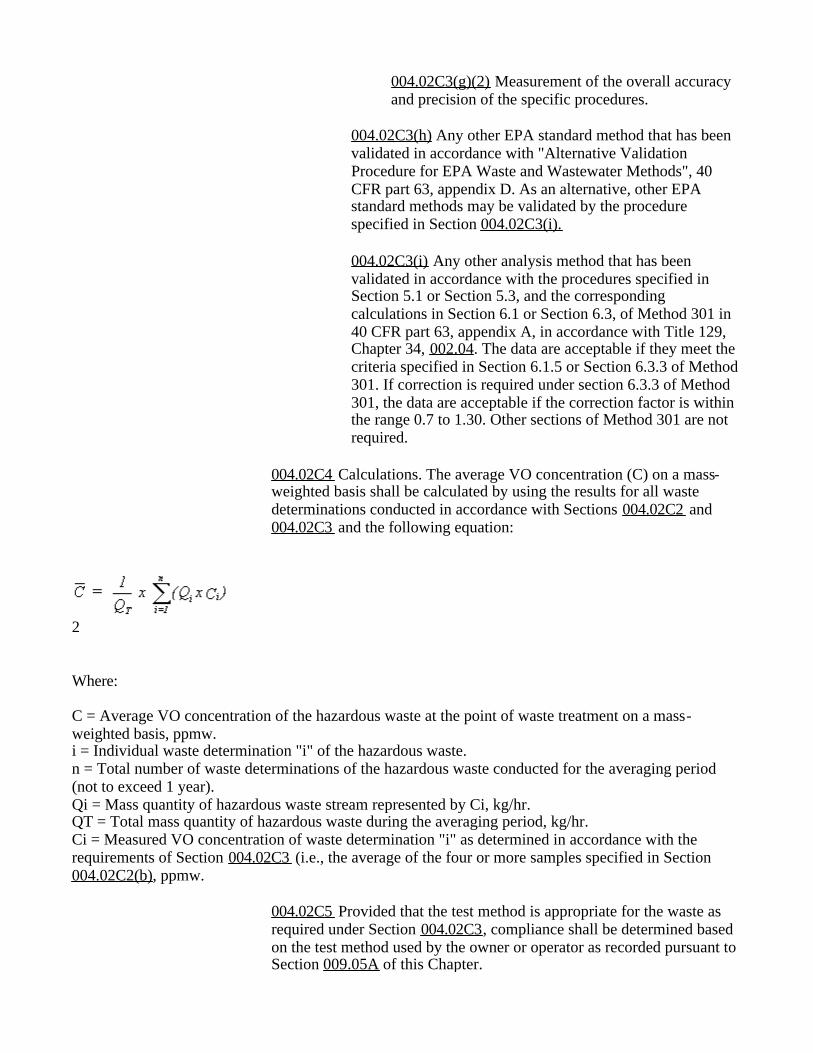
004.01C3(h) Any other EPA standard method that has been validated in accordance with "Alternative Validation Procedure for EPA Waste and Wastewater Methods", 40 CFR part 63, appendix D. As an alternative, other EPA standard methods may be validated by the procedure specified in Section 004.01C3(i).
004.01C3(i) Any other analysis method that has been validated in accordance with the procedures specified in Section 5.1 or Section 5.3, and the corresponding calculations in Section 6.1 or Section 6.3, of Method 301 in 40 CFR part 63, appendix A, in accordance with Title 129, Chapter 34, 002.04. The data are acceptable if they meet the criteria specified in Section 6.1.5 or Section 6.3.3 of Method 301. If correction is required under section 6.3.3 of Method 301, the data are acceptable if the correction factor is within the range 0.7 to 1.30. Other sections of Method 301 are not required.
004.01C4 Calculations. 004.01C4(a) The average VO concentration (C) on a mass-weighted basis shall be calculated by using the results for all waste determinations conducted in accordance with Section 004.01C2 and 004.01C3 and the following equation:
1

Where: C = Average VO concentration of the hazardous waste at the point of waste origination on a mass-weighted basis, ppmw. i = Individual waste determination "i" of the hazardous waste. n = Total number of waste determinations of the hazardous waste conducted for the averaging period (not to exceed 1 year). Qi = Mass quantity of hazardous waste stream represented by Ci, kg/hr. QT = Total mass quantity of hazardous waste during the averaging period, kg/hr. Ci = Measured VO concentration of waste determination "i" as determined in accordance with the requirements of Section 004.01C3 (i.e., the average of the four or more samples specified in Section 004.01C2(b)), ppmw.
004.01C4(b) For the purpose of determining Ci, for individual waste samples analyzed in accordance with Section 004.01C3, the owner or operator shall account for VO concentrations determined to be below the limit of detection of the analytical method by using the following VO concentration:
004.01C4(b)(1) If Method 25D in 40 CFR Part 60, Appendix A, as incorporated by reference in as Title 129, Chapter 18, 001.64, is used for the analysis, one-half the blank value determined in the method at section 4.4 of Method 25D. 004.01C(b)(2) If any other analytical method is used, one-half the sum of the limits of detection established for each organic constituent in the waste that has a Henry's law constant value at least 0.1 mole-fraction-in-the-gas-phase/mole-fraction-in-the-liquid-phase (0.1 Y/X) (which can also be expressed as 1.8 x 10⁻⁶ atmospheres/gram-mole/m3) at 25 degrees Celsius.
004.01C5 Provided that the test method is appropriate for the waste as required under Section 004.01C3, NDEQ will determine compliance based on the test method used by the owner or operator as recorded pursuant to Section 009.05A of this Chapter.
004.01D Use of generator knowledge to determine average VO concentration of a hazardous waste at the point of waste origination.
004.01D1 Documentation shall be prepared that presents the information used as the basis for the owner's or operator's knowledge of the hazardous waste stream's average VO concentration. Examples of information that may be used as the basis for knowledge include: Material balances for the source or process generating the hazardous waste stream; constituent-specific chemical test data for the hazardous waste stream from previous testing that are still applicable to the current waste stream; previous test data for other locations managing the same type of waste stream; or other knowledge based on information included in manifests, shipping papers, or waste certification notices.

004.01D2 If test data are used as the basis for knowledge, then the generator shall document the test method, sampling protocol, and the means by which sampling variability and analytical variability are accounted for in the determination of the average VO concentration. For example, a generator may use organic concentration test data for the hazardous waste stream that are validated in accordance with Method 301 in 40 CFR part 63, appendix A, in accordance with Title 129, Chapter 34, 002.04 as the basis for knowledge of the waste.
004.01D3 A generator using chemical constituent-specific concentration test data as the basis for knowledge of the hazardous waste may adjust the test data to the corresponding average VO concentration value which would have been obtained had the waste samples been analyzed using Method 25D in 40 CFR part 60, appendix A, as incorporated by reference in Title 129, Chapter 18, 001.64. To adjust these data, the measured concentration for each individual chemical constituent contained in the waste is multiplied by the appropriate constituent-specific adjustment factor (fm25D).
004.01D4 In the event that the Director and the generator disagree on a determination of the average VO concentration for a hazardous waste stream using knowledge, then the results from a determination of average VO concentration using direct measurement as specified in Section 004.01C shall be used to establish compliance with the applicable requirements of this subpart. The Director may perform or request that the generator perform this determination using direct measurement. The owner or operator may choose one or more appropriate methods to analyze each collected sample in accordance with the requirements of Section 004.01C3.
004.02 Waste determination procedures for treated hazardous waste.
004.02A A generator shall perform the applicable waste determination for each treated hazardous waste placed in a waste management unit exempted under the provisions of Sections 003.03B1 through 003.03B6 from using air emission controls in accordance with standards specified in Sections 005 through 007, as applicable to the waste management unit. 004.02A1 An initial determination of the average VO concentration of the waste stream shall be made before the first time any portion of the material in the treated waste stream is placed in a waste management unit exempted under the provisions of Sections 003.03B, 003.03C, and 003.03D of this Chapter from using air emission controls, and thereafter update the information used for the waste determination at least once every 12 months following the date of the initial waste determination; and 004.02A2 Perform a new waste determination whenever changes to the process generating or treating the waste stream are reasonably likely to cause the average VO concentration of the hazardous waste to increase to a level such that the applicable treatment conditions specified in Sections 003.03B, 003.03C, or 003.03D of this Chapter are not achieved.

004.02B The generator shall designate and record the specific provision in Section 003.03B under which the waste determination is being performed. The waste determination for the treated hazardous waste shall be performed using the applicable procedures specified in paragraphs (b)(3) through (b)(9) of this section.
004.02C Procedure to determine the average VO concentration of a hazardous waste at the point of waste treatment.
004.02C1 Identification. The generator shall identify and record the point of waste treatment for the hazardous waste.
004.02C2 Sampling. Samples of the hazardous waste stream shall be collected at the point of waste treatment in a manner such that volatilization of organics contained in the waste and in the subsequent sample is minimized and an adequately representative sample is collected and maintained for analysis by the selected method.
004.02C2(a) The averaging period to be used for determining the average VO concentration for the hazardous waste stream on a mass-weighted average basis shall be designated and recorded. The averaging period can represent any time interval that the generator determines is appropriate for the hazardous waste stream but shall not exceed 1 year.
004.02C2(b) A sufficient number of samples, but no less than four samples, shall be collected and analyzed for a hazardous waste determination. All of the samples for a given waste determination shall be collected within a one-hour period. The average of the four or more sample results constitutes a waste determination for the waste stream. One or more waste determinations may be required to represent the complete range of waste compositions and quantities that occur during the entire averaging period due to normal variations in the operating conditions for the process generating or treating the hazardous waste stream. Examples of such normal variations are seasonal variations in waste quantity or fluctuations in ambient temperature.
004.02C2(c) All samples shall be collected and handled in accordance with written procedures prepared by the generator and documented in a site sampling plan. This plan shall describe the procedure by which representative samples of the hazardous waste stream are collected such that a minimum loss of organics occurs throughout the sample collection and handling process, and by which sample integrity is maintained. A copy of the written sampling plan shall be maintained on-site in the facility operating records. An example of an acceptable sampling plan includes a plan incorporating sample collection and handling procedures in accordance with the requirements specified in "Test Methods for Evaluating Solid Waste, Physical/Chemical Methods,"
EPA Publication No. SW-846 (incorporated by reference--refer to Chapter 1, 003), or in Method 25D in 40 CFR part 60, appendix A, as incorporated by reference in Title 129, Chapter 18, 001.64. 004.02C2(d) Sufficient information, as specified in the "site sampling plan" required under Section 004.02C2(c) of this Chapter, shall be prepared and recorded to document the waste quantity represented by the samples and, as applicable, the operating conditions for the process treating the hazardous waste represented by the samples.
004.02C3 Analysis. Each collected sample shall be prepared and analyzed in accordance with one or more of the methods listed in Sections 004.02C3(a) through 004.02C3(i), including appropriate quality assurance and quality control (QA/QC) checks and use of target compounds for calibration. When the owner or operator is making a waste determination for a treated hazardous waste that is to be compared to an average VO concentration at the point of waste origination or the point of waste entry to the treatment system, to determine if the conditions of Section 003.03B1 through 003.03B6 are met, then the waste samples shall be prepared and analyzed using the same method or methods as were used in making the initial waste determinations at the point of waste origination or at the point of entry to the treatment system. If Method 25D in 40 CFR part 60, appendix A, as incorporated by reference in Title 129, Chapter 18, 001.64, is not used, then one or more methods should be chosen that are appropriate to ensure that the waste determination accounts for and reflects all organic compounds in the waste with Henry's law constant values at least 0.1 mole-fraction-in-the-gas-phase/mole-fraction-in-the-liquid-phase (0.1 Y/X) [which can also be expressed as 1.8 x 10⁻⁶ atmospheres/gram-mole/m3] at 25 degrees Celsius. Each of the analytical methods listed in Sections 004.02C3(b) through 004.02C3(g) of this section has an associated list of approved chemical compounds, for which EPA considers the method appropriate for measurement. If a generator uses Method 624, 625, 1624, or 1625 in 40 CFR part 136, appendix A to analyze one or more compounds that are not on that method's published list, the Alternative Test Procedure contained in 40 CFR 136.4 and 136.5 must be followed. If a generator uses EPA Method 8260 or 8270 in "Test Methods for Evaluating Solid Waste, Physical/Chemical Methods", EPA Publication SW-846 (incorporated by reference--refer to Chapter 1, 003) to analyze one or more compounds that are not on that method's published list, the procedures in Section 004.02C3(h) must be followed. At the owner's or operator's discretion, the owner or operator may adjust test data measured by a method other than Method 25D to the corresponding average VO concentration value which would have been obtained had the waste samples been analyzed using Method 25D in 40 CFR part 60, Appendix A. To adjust these data, the measured concentration of each individual chemical constituent contained in the waste is multiplied by the appropriate constituent-specific adjustment factor (fm25D). If the owner or operator elects to adjust test data, the adjustment must be made to all
individual chemical constituents with a Henry's law constant value greater than or equal to 0.1 Y/X at 25 degrees Celsius contained in the waste. Constituent-specific adjustment factors (fm25D) can be obtained by contacting the Waste and Chemical Processes Group, Office of Air Quality Planning and Standards, Research Triangle Park, NC 27711.
004.02C3(a) Method 25D in 40 CFR part 60, appendix A, as incorporated by reference in Title 129, Chapter 18, 001.64.
004.02C3(b) Method 624 in 40 CFR part 136, appendix A.
004.02C3(c) Method 625 in 40 CFR part 136, appendix A. Perform corrections to the compounds for which the analysis is being conducted based on the "accuracy as recovery" using the factors in Table 7 of the method.
004.02C3(d) Method 1624 in 40 CFR part 136, appendix A.
004.02C3(e) Method 1625 in 40 CFR part 136, appendix A.
004.02C3(f) Method 8260 in "Test Methods for Evaluating Solid Waste, Physical/Chemical Methods", EPA Publication SW-846, (incorporated by reference--refer to Chapter 1, 003). Maintain a formal quality assurance program consistent with the requirements of Method 8260. The quality assurance program shall include the following elements:
004.02C3(f)(1) Documentation of site-specific procedures to minimize the loss of compounds due to volatilization, biodegradation, reaction, or sorption during the sample collection, storage, preparation, introduction, and analysis steps.
004.02C3(f)(2) Measurement of the overall accuracy and precision of the specific procedures.
004.02C3(g) Method 8270 in "Test Methods for Evaluating Solid Waste, Physical/Chemical Methods", EPA Publication SW-846, (incorporated by reference--refer to Chapter 1, 003). Maintain a formal quality assurance program consistent with the requirements of Method 8270. The quality assurance program shall include the following elements:
004.02C3(g)(1) Documentation of site-specific procedures to minimize the loss of compounds due to volatilization, biodegradation, reaction, or sorption during the sample collection, storage, preparation, introduction, and analysis steps.
004.02C3(g)(2) Measurement of the overall accuracy and precision of the specific procedures.
004.02C3(h) Any other EPA standard method that has been validated in accordance with "Alternative Validation Procedure for EPA Waste and Wastewater Methods", 40 CFR part 63, appendix D. As an alternative, other EPA standard methods may be validated by the procedure specified in Section 004.02C3(i).
004.02C3(i) Any other analysis method that has been validated in accordance with the procedures specified in Section 5.1 or Section 5.3, and the corresponding calculations in Section 6.1 or Section 6.3, of Method 301 in 40 CFR part 63, appendix A, in accordance with Title 129, Chapter 34, 002.04. The data are acceptable if they meet the criteria specified in Section 6.1.5 or Section 6.3.3 of Method 301. If correction is required under section 6.3.3 of Method 301, the data are acceptable if the correction factor is within the range 0.7 to 1.30. Other sections of Method 301 are not required.
004.02C4 Calculations. The average VO concentration (C) on a mass-weighted basis shall be calculated by using the results for all waste determinations conducted in accordance with Sections 004.02C2 and 004.02C3 and the following equation:
2 Where: C = Average VO concentration of the hazardous waste at the point of waste treatment on a mass-weighted basis, ppmw. i = Individual waste determination "i" of the hazardous waste. n = Total number of waste determinations of the hazardous waste conducted for the averaging period (not to exceed 1 year). Qi = Mass quantity of hazardous waste stream represented by Ci, kg/hr. QT = Total mass quantity of hazardous waste during the averaging period, kg/hr. Ci = Measured VO concentration of waste determination "i" as determined in accordance with the requirements of Section 004.02C3 (i.e., the average of the four or more samples specified in Section 004.02C2(b), ppmw.
004.02C5 Provided that the test method is appropriate for the waste as required under Section 004.02C3, compliance shall be determined based on the test method used by the owner or operator as recorded pursuant to Section 009.05A of this Chapter.

004.02D Procedure to determine the exit concentration limit (Ct) for a treated hazardous waste.
004.02D1 The point of waste origination for each hazardous waste treated by the process at the same time shall be identified.
004.02D2 If a single hazardous waste stream is identified in Section 004.02D1, then the exit concentration limit (Ct) shall be 500 ppmw.
004.02D3 If more than one hazardous waste stream is identified in Section 004.02D1, then the average VO concentration of each hazardous waste stream at the point of waste origination shall be determined in accordance with the requirements of paragraph (a) of this section. The exit concentration limit (Ct) shall be calculated by using the results determined for each individual hazardous waste stream and the following equation:
3 Where: Ct = Exit concentration limit for treated hazardous waste, ppmw. x = Individual hazardous waste stream "x" that has an average VO concentration less than 500 ppmw at the point of waste origination as determined in accordance with the requirements of Section 004.01. y = Individual hazardous waste stream "y" that has an average VO concentration equal to or greater than 500 ppmw at the point of waste origination as determined in accordance with the requirements of Section 004.01. m = Total number of "x" hazardous waste streams treated by process. n = Total number of "y" hazardous waste streams treated by process. Qx = Annual mass quantity of hazardous waste stream "x," kg/yr. Qy = Annual mass quantity of hazardous waste stream "y," kg/yr. x = Average VO concentration of hazardous waste stream "x" at the point of waste origination as determined in accordance with the requirements of Section 004.01, ppmw.
004.02E Procedure to determine the organic reduction efficiency (R) for a treated hazardous waste.
004.02E1 The organic reduction efficiency (R) for a treatment process shall be determined based on results for a minimum of three consecutive runs.
004.02E2 All hazardous waste streams entering the treatment process and all hazardous waste streams exiting the treatment process shall be identified. The generator shall prepare a sampling plan for measuring

these streams that accurately reflects the retention time of the hazardous waste in the process.
004.02E3 For each run, information shall be determined for each hazardous waste stream identified in Section 004.02E2 using the following procedures:
004.02E3(a) The mass quantity of each hazardous waste stream entering the process (Qb) and the mass quantity of each hazardous waste stream exiting the process (Qa) shall be determined.
004.02E3(b) The average VO concentration at the point of waste origination of each hazardous waste stream entering
the process ( 4b) during the run shall be determined in accordance with the requirements of Section 004.01C. The average VO concentration at the point of waste treatment of
each waste stream exiting the process ( 5a) during the run shall be determined in accordance with the requirements of Section 004.02C.
004.02E4 The waste volatile organic mass flow entering the process (Eb) and the waste volatile organic mass flow exiting the process (Ea) shall be calculated by using the results determined in accordance with Section 004.02E3 and the following equations:
6
7 Where: Ea = Waste volatile organic mass flow exiting process, kg/hr. Eb = Waste volatile organic mass flow entering process, kg/hr. m = Total number of runs (at least 3) j = Individual run "j" Qb = Mass quantity of hazardous waste entering process during run "j," kg/hr. Qa = Average mass quantity of hazardous waste exiting process during run "j," kg/hr.
8a = Average VO concentration of hazardous waste exiting process during run "j" as determined in accordance with the requirements of Section 004.02C, ppmw.
9b = Average VO concentration of hazardous waste entering process during run "j" as determined in
accordance with the requirements of Section 004.01C, ppmw.
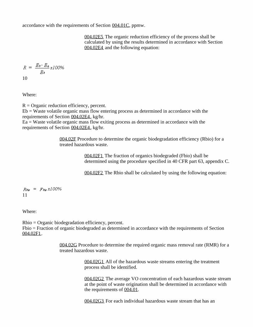
004.02E5 The organic reduction efficiency of the process shall be calculated by using the results determined in accordance with Section 004.02E4 and the following equation:
10 Where: R = Organic reduction efficiency, percent. Eb = Waste volatile organic mass flow entering process as determined in accordance with the requirements of Section 004.02E4, kg/hr. Ea = Waste volatile organic mass flow exiting process as determined in accordance with the requirements of Section 004.02E4, kg/hr.
004.02F Procedure to determine the organic biodegradation efficiency (Rbio) for a treated hazardous waste.
004.02F1 The fraction of organics biodegraded (Fbio) shall be determined using the procedure specified in 40 CFR part 63, appendix C.
004.02F2 The Rbio shall be calculated by using the following equation:
11 Where: Rbio = Organic biodegradation efficiency, percent. Fbio = Fraction of organic biodegraded as determined in accordance with the requirements of Section 004.02F1.
004.02G Procedure to determine the required organic mass removal rate (RMR) for a treated hazardous waste.
004.02G1 All of the hazardous waste streams entering the treatment process shall be identified.
004.02G2 The average VO concentration of each hazardous waste stream at the point of waste origination shall be determined in accordance with the requirements of 004.01.
004.02G3 For each individual hazardous waste stream that has an

average VO concentration equal to or greater than 500 ppmw at the point of waste origination, the average volumetric flow rate and the density of the hazardous waste stream at the point of waste origination shall be determined.
004.02G4 The RMR shall be calculated by using the average VO concentration, average volumetric flow rate, and density determined for each individual hazardous waste stream, and the following equation:
12 Where: RMR = Required organic mass removal rate, kg/hr. y = Individual hazardous waste stream "y" that has an average VO concentration equal to or greater than 500 ppmw at the point of waste origination as determined in accordance with the requirements of Section 004.01. n = Total number of "y" hazardous waste streams treated by process. Vy = Average volumetric flow rate of hazardous waste stream "y" at the point of waste origination, m3/hr. ky = Density of hazardous waste stream "y," kg/m3
13y = Average VO concentration of hazardous waste stream "y" at the point of waste origination as determined in accordance with the requirements of Section 004.01, ppmw.
004.02H Procedure to determine the actual organic mass removal rate (MR) for a treated hazardous waste.
004.02H1 The MR shall be determined based on results for a minimum of three consecutive runs. The sampling time for each run shall be 1 hour.
004.02H2 The waste volatile organic mass flow entering the process (Eb) and the waste volatile organic mass flow exiting the process (Ea) shall be determined in accordance with the requirements of Section 004.02E4.
004.02H3 The MR shall be calculated by using the mass flow rate determined in accordance with the requirements of Section 004.02H2 of this section and the following equation:
MR = Eb-Ea Where: MR = Actual organic mass removal rate, kg/hr.
Eb = Waste volatile organic mass flow entering process as determined in accordance with the requirements of Section 004.02E4, kg/hr. Ea = Waste volatile organic mass flow exiting process as determined in accordance with the requirements of Section 004.02E4, kg/hr.
004.02I Procedure to determine the actual organic mass biodegradation rate (MRbio) for a treated hazardous waste.
004.02I1 The MRbio shall be determined based on results for a minimum of three consecutive runs. The sampling time for each run shall be 1 hour.
004.02I2 The waste organic mass flow entering the process (Eb) shall be determined in accordance with the requirements of Section 004.02E4.
004.02I3 The fraction of organic biodegraded (Fbio) shall be determined using the procedure specified in 40 CFR part 63, appendix C.
004.02I4 The MRbio shall be calculated by using the mass flow rates and fraction of organic biodegraded determined in accordance with the requirements of Section 004.02I2 and 004.02I3, of this section, respectively, and the following equation:
MRbio = Eb x Fbio Where: MRbio = Actual organic mass biodegradation rate, kg/hr. Eb = Waste organic mass flow entering process as determined in accordance with the requirements of Section 004.02E4, kg/hr. Fbio = Fraction of organic biodegraded as determined in accordance with the requirements of Section 004.02I3.
004.03 Procedure to determine the maximum organic vapor pressure of a hazardous waste in a tank.
004.03A A generator shall determine the maximum organic vapor pressure for each hazardous waste placed in a tank using Tank Level 1 controls in accordance with the standards specified in Section 005.03.
004.03B A generator shall use either direct measurement as specified in 004.03C or knowledge of the waste as specified by Section 004.03D to determine the maximum organic vapor pressure which is representative of the hazardous waste composition stored or treated in the tank.
004.03C Direct measurement to determine the maximum organic vapor pressure of a hazardous waste.
004.03C1 Sampling. A sufficient number of samples shall be collected to be representative of the waste contained in the tank. All samples shall be

collected and handled in accordance with written procedures prepared by the generator and documented in a site sampling plan. This plan shall describe the procedure by which representative samples of the hazardous waste are collected such that a minimum loss of organics occurs throughout the sample collection and handling process and by which sample integrity is maintained. A copy of the written sampling plan shall be maintained on-site in the facility operating records. An example of an acceptable sampling plan includes a plan incorporating sample collection and handling procedures in accordance with the requirements specified in "Test Methods for Evaluating Solid Waste, Physical/Chemical Methods," EPA Publication No. SW-846, (incorporated by reference--refer to Chapter 1, 003, or in Method 25D in 40 CFR part 60, appendix A, as incorporated by reference in Title 129, Chapter 18, 001.64.
004.03C2 Analysis. Any appropriate one of the following methods may be used to analyze the samples and compute the maximum organic vapor pressure of the hazardous waste:
004.03C2(a) Method 25E in 40 CFR part 60 appendix A, as incorporated by reference in Title 129, Chapter 18, 001.64;
004.03C2(b) Methods described in American Petroleum Institute Publication 2517, Third Edition, February 1989, "Evaporative Loss from External Floating-Roof Tanks," (incorporated by reference--refer to Chapter 1, 003); 004.03C2(c) Methods obtained from standard reference texts; 004.03C2(d) ASTM Method 2879-92 (incorporated by reference--refer to Chapter 1, 003); and 004.03C2(e) Any other method approved by the Director.
004.03D Use of knowledge to determine the maximum organic vapor pressure of the hazardous waste. Documentation shall be prepared and recorded that presents the information used as the basis for the owner's or operator's knowledge that the maximum organic vapor pressure of the hazardous waste is less than the maximum vapor pressure limit listed in Section 005.02A1 for the applicable tank design capacity category. An example of information that may be used is documentation that the hazardous waste is generated by a process for which at other locations it previously has been determined by direct measurement that the waste maximum organic vapor pressure is less than the maximum vapor pressure limit for the appropriate tank design capacity category.
004.04 Procedure for determining no detectable organic emissions for the purpose of complying with this subpart:
004.04A The test shall be conducted in accordance with the procedures specified in Method 21 of 40 CFR part 60, appendix A, as incorporated by reference in Title 129, Chapter 18, 001.64. Each potential leak interface (i.e., a location where organic vapor

leakage could occur) on the cover and associated closure devices shall be checked. Potential leak interfaces that are associated with covers and closure devices include, but are not limited to: The interface of the cover and its foundation mounting; the periphery of any opening on the cover and its associated closure device; and the sealing seat interface on a spring-loaded pressure relief valve.
004.04B The test shall be performed when the unit contains a hazardous waste having an organic concentration representative of the range of concentrations for the hazardous waste expected to be managed in the unit. During the test, the cover and closure devices shall be secured in the closed position.
004.04C The detection instrument shall meet the performance criteria of Method 21 of 40 CFR part 60, appendix A, as incorporated by reference in Title 129, Chapter 18, 001.64, except the instrument response factor criteria in section 3.1.2(a) of Method 21 shall be for the average composition of the organic constituents in the hazardous waste placed in the waste management unit, not for each individual organic constituent.
004.04D The detection instrument shall be calibrated before use on each day of its use by the procedures specified in Method 21 of 40 CFR part 60, appendix A, as incorporated by reference in Title 129, Chapter 18, 001.64.
004.04E Calibration gases shall be as follows:
004.04E1 Zero air (less than 10 ppmv hydrocarbon in air), and
004.04E2 A mixture of methane or n-hexane and air at a concentration of approximately, but less than 10,000 ppmv methane or n-hexane.
004.04F The background level shall be determined according to the procedures in Method 21 of 40 CFR part 60, appendix A, as incorporated by reference in Title 129, Chapter 18, 001.64.
004.04G Each potential leak interface shall be checked by traversing the instrument probe around the potential leak interface as close to the interface as possible, as described in Method 21 of 40 CFR part 60, appendix A, as incorporated by reference in Title 129, Chapter 18, 001.64. In the case when the configuration of the cover or closure device prevents a complete traverse of the interface, all accessible portions of the interface shall be sampled. In the case when the configuration of the closure device prevents any sampling at the interface and the device is equipped with an enclosed extension or horn (e.g., some pressure relief devices), the instrument probe inlet shall be placed at approximately the center of the exhaust area to the atmosphere.
004.04H The arithmetic difference between the maximum organic concentration indicated by the instrument and the background level shall be compared with the value of 500 ppmv except when monitoring a seal around a rotating shaft that passes through a cover opening, in which case the comparison shall be as specified in Section 004.04I. If the difference is less than 500 ppmv, then the potential leak interface is determined to operate with no detectable organic emissions.

004.04I For the seals around a rotating shaft that passes through a cover opening, the arithmetic difference between the maximum organic concentration indicated by the instrument and the background level shall be compared with the value of 10,000 ppmw. If the difference is less than 10,000 ppmw, then the potential leak interface is determined to operate with no detectable organic emissions.
005 Standards: Tanks.
005.01 The provisions of this section apply to the control of air pollutant emissions from tanks for which Section 003.02 references the use of this section for such air emission control.
005.02 The generator shall control air pollutant emissions from each tank subject to this section in accordance with the following requirements, as applicable:
005.02A For a tank that manages hazardous waste that meets all of the conditions specified in Sections 005.02A1 through 005.02A3, the generator shall control air pollutant emissions from the tank in accordance with the Tank Level 1 controls specified in Section 005.03 or the Tank Level 2 controls specified in Section 005.04.
005.02A1 The hazardous waste in the tank has a maximum organic vapor pressure which is less than the maximum organic vapor pressure limit for the tank's design capacity category as follows:
005.02A1(a) For a tank design capacity equal to or greater than 151 m3, the maximum organic vapor pressure limit for the tank is 5.2 kPa.
005.02A1(b) For a tank design capacity equal to or greater than 75 m3 less than 151 m3, the maximum organic vapor pressure limit for the tank is 27.6 kPa.
005.02A1(c) For a tank design capacity less than 75 m3, the maximum organic vapor pressure limit for the tank is 76.6 kPa.
005.02A2 The hazardous waste in the tank is not heated by the generator to a temperature that is greater than the temperature at which the maximum organic vapor pressure of the hazardous waste is determined for the purpose of complying with Section 005.02A1.
005.02A3 The hazardous waste in the tank is not treated by the generator using a waste stabilization process, as defined in Section 002.
005.02B For a tank that manages hazardous waste that does not meet all of the conditions specified in Sections 005.02A1 through 005.02A3, the generator shall control air pollutant emissions from the tank by using Tank Level 2 controls in accordance with the requirements of 005.04. Examples of tanks required to use Tank Level 2 controls include: A tank used for a waste stabilization process; and a tank for

which the hazardous waste in the tank has a maximum organic vapor pressure that is equal to or greater than the maximum organic vapor pressure limit for the tank's design capacity category as specified in Section 005.02A1.
005.03 Owners and operators controlling air pollutant emissions from a tank using Tank Level 1 controls shall meet the requirements specified in Section 005.03A through 005.03D:
005.03A The generator shall determine the maximum organic vapor pressure for a hazardous waste to be managed in the tank using Tank Level 1 controls before the first time the hazardous waste is placed in the tank. The maximum organic vapor pressure shall be determined using the procedures specified in Section 004.03. Thereafter, the generator shall perform a new determination whenever changes to the hazardous waste managed in the tank could potentially cause the maximum organic vapor pressure to increase to a level that is equal to or greater than the maximum organic vapor pressure limit for the tank design capacity category specified in Section 005.02A1, as applicable to the tank.
005.03B The tank shall be equipped with a fixed roof designed to meet the following specifications:
005.03B1 The fixed roof and its closure devices shall be designed to form a continuous barrier over the entire surface area of the hazardous waste in the tank. The fixed roof may be a separate cover installed on the tank (e.g., a removable cover mounted on an open-top tank) or may be an integral part of the tank structural design (e.g., a horizontal cylindrical tank equipped with a hatch).
005.03B2 The fixed roof shall be installed in a manner such that there are no visible cracks, holes, gaps, or other open spaces between roof section joints or between the interface of the roof edge and the tank wall.
005.03B3 Each opening in the fixed roof, and any manifold system associated with the fixed roof, shall be either:
005.03B3(a) Equipped with a closure device designed to operate such that when the closure device is secured in the closed position there are no visible cracks, holes, gaps, or other open spaces in the closure device or between the perimeter of the opening and the closure device; or
005.03B3(b) Connected by a closed-vent system that is vented to a control device. The control device shall remove or destroy organics in the vent stream, and shall be operating whenever hazardous waste is managed in the tank, except as provided for in Sections 005.03B3(b)(1) and (2).
005.03B3(b)(1) During periods it is necessary to provide access to the tank for performing the activities of Section 005.03B3(b)(2), venting of the vapor headspace underneath the fixed roof to the control device is not required, opening of closure devices is

allowed, and removal of the fixed roof is allowed. Following completion of the activity, the owner or operator shall promptly secure the closure device in the closed position or reinstall the cover, as applicable, and resume operation of the control device. 005.03B3(b)(2) During periods of routine inspection, maintenance, or other activities needed for normal operations and for the removal of accumulated sludge or other residues from the bottom of the tank.
005.03B4 The fixed roof and its closure devices shall be made of suitable materials that will minimize exposure of the hazardous waste to the atmosphere, to the extent practical, and will maintain the integrity of the fixed roof and closure devices throughout their intended service life. Factors to be considered when selecting the materials for and designing the fixed roof and closure devices shall include: Organic vapor permeability, the effects of any contact with the hazardous waste or its vapors managed in the tank; the effects of outdoor exposure to wind, moisture, and sunlight; and the operating practices used for the tank on which the fixed roof is installed.
005.03C Whenever a hazardous waste is in the tank, the fixed roof shall be installed with each closure device secured in the closed position except as follows:
005.03C1 Opening of closure devices or removal of the fixed roof is allowed at the following times:
005.03C1(a) To provide access to the tank for performing routine inspection, maintenance, or other activities needed for normal operations. Examples of such activities include those times when a worker needs to open a port to sample the liquid in the tank, or when a worker needs to open a hatch to maintain or repair equipment. Following completion of the activity, the generator shall promptly secure the closure device in the closed position or reinstall the cover, as applicable, to the tank.
005.03C(b) To remove accumulated sludge or other residues from the bottom of tank.
005.03C2 Opening of a spring-loaded pressure-vacuum relief valve, conservation vent, or similar type of pressure relief device which vents to the atmosphere is allowed during normal operations for the purpose of maintaining the tank internal pressure in accordance with the tank design specifications. The device shall be designed to operate with no detectable organic emissions when the device is secured in the closed position. The settings at which the device opens shall be established such that the device remains in the closed position whenever the tank internal pressure is within the internal pressure operating range determined by the generator based on the tank manufacturer recommendations, applicable

regulations, fire protection and prevention codes, standard engineering codes and practices, or other requirements for the safe handling of flammable, ignitable, explosive, reactive, or hazardous materials. Examples of normal operating conditions that may require these devices to open are during those times when the tank internal pressure exceeds the internal pressure operating range for the tank as a result of loading operations or diurnal ambient temperature fluctuations.
005.03C3 Opening of a safety device, as defined in Section 002, is allowed at any time conditions require doing so to avoid an unsafe condition.
005.03D The generator shall inspect the air emission control equipment in accordance with the following requirements.
005.03D1 The fixed roof and its closure devices shall be visually inspected by the generator to check for defects that could result in air pollutant emissions. Defects include, but are not limited to, visible cracks, holes, or gaps in the roof sections or between the roof and the tank wall; broken, cracked, or otherwise damaged seals or gaskets on closure devices; and broken or missing hatches, access covers, caps, or other closure devices.
005.03D2 The generator shall perform an initial inspection of the fixed roof and its closure devices on or before the date that the tank becomes subject to this section. Thereafter, the generator shall perform the inspections at least once every year except under the special conditions provided for in Section 005.12.
005.03D3 In the event that a defect is detected, the generator shall repair the defect in accordance with the requirements of Section 005.11.
005.03D4 The generator shall maintain a record of the inspection in accordance with the requirements specified in Section 009.02.
005.04 Owners and operators controlling air pollutant emissions from a tank using Tank Level 2 controls shall use one of the following tanks:
005.04A A fixed-roof tank equipped with an internal floating roof in accordance with the requirements specified in Section 005.05;
005.04B A tank equipped with an external floating roof in accordance with the requirements specified in Section 005.06;
005.04C A tank vented through a closed-vent system to a control device in accordance with the requirements specified in Section 005.07;
005.04D A pressure tank designed and operated in accordance with the requirements specified in Section 005.08; or

005.04E A tank located inside an enclosure that is vented through a closed-vent system to an enclosed combustion control device in accordance with the requirements specified in Section 005.09.
005.05 The generator who controls air pollutant emissions from a tank using a fixed-roof with an internal floating roof shall meet the requirements specified in Sections 005.05A through 005.05C.
005.05A The tank shall be equipped with a fixed roof and an internal floating roof in accordance with the following requirements:
005.05A1 The internal floating roof shall be designed to float on the liquid surface except when the floating roof must be supported by the leg supports.
005.05A2 The internal floating roof shall be equipped with a continuous seal between the wall of the tank and the floating roof edge that meets either of the following requirements:
005.05A2(a) A single continuous seal that is either a liquid-mounted seal or a metallic shoe seal, as defined in Section 002; or
005.05A2(b) Two continuous seals mounted one above the other. The lower seal may be a vapor-mounted seal.
005.05A3 The internal floating roof shall meet the following specifications:
005.05A3(a) Each opening in a noncontact internal floating roof except for automatic bleeder vents (vacuum breaker vents) and the rim space vents is to provide a projection below the liquid surface.
005.05A3(b) Each opening in the internal floating roof shall be equipped with a gasketed cover or a gasketed lid except for leg sleeves, automatic bleeder vents, rim space vents, column wells, ladder wells, sample wells, and stub drains.
005.05A3(c) Each penetration of the internal floating roof for the purpose of sampling shall have a slit fabric cover that covers at least 90 percent of the opening.
005.05A3(d) Each automatic bleeder vent and rim space vent shall be gasketed.
005.05A3(e) Each penetration of the internal floating roof that allows for passage of a ladder shall have a gasketed sliding cover.

005.05A3(f) Each penetration of the internal floating roof that allows for passage of a column supporting the fixed roof shall have a flexible fabric sleeve seal or a gasketed sliding cover.
005.05B The generator shall operate the tank in accordance with the following requirements:
005.05B1 When the floating roof is resting on the leg supports, the process of filling, emptying, or refilling shall be continuous and shall be completed as soon as practical.
005.05B2 Automatic bleeder vents are to be set closed at all times when the roof is floating, except when the roof is being floated off or is being landed on the leg supports.
005.05B3 Prior to filling the tank, each cover, access hatch, gauge float well or lid on any opening in the internal floating roof shall be bolted or fastened closed (i.e., no visible gaps). Rim space vents are to be set to open only when the internal floating roof is not floating or when the pressure beneath the rim exceeds the manufacturer's recommended setting.
005.05C The generator shall inspect the internal floating roof in accordance with the procedures specified as follows:
005.05C1 The floating roof and its closure devices shall be visually inspected by the generator to check for defects that could result in air pollutant emissions. Defects include, but are not limited to: The internal floating roof is not floating on the surface of the liquid inside the tank; liquid has accumulated on top of the internal floating roof; any portion of the roof seals have detached from the roof rim; holes, tears, or other openings are visible in the seal fabric; the gaskets no longer close off the hazardous waste surface from the atmosphere; or the slotted membrane has more than 10 percent open area.
005.05C2 The generator shall inspect the internal floating roof components as follows except as provided in paragraph (e)(3)(iii) of this section:
005.05C2(a) Visually inspect the internal floating roof components through openings on the fixed-roof (e.g., manholes and roof hatches) at least once every 12 months after initial fill, and
005.05C2(b) Visually inspect the internal floating roof, primary seal, secondary seal (if one is in service), gaskets, slotted membranes, and sleeve seals (if any) each time the tank is emptied and degassed and at least every 10 years.

005.05C3 As an alternative to performing the inspections specified in Section 005.05C2 for an internal floating roof equipped with two continuous seals mounted one above the other, the generator may visually inspect the internal floating roof, primary and secondary seals, gaskets, slotted membranes, and sleeve seals (if any) each time the tank is emptied and degassed and at least every 5 years.
005.05C4 Prior to each inspection required by paragraph Section 005.05C2 or 005.05C3, the generator shall notify the Director in advance of each inspection to provide the Director with the opportunity to have an observer present during the inspection. The generator shall notify the Director of the date and location of the inspection as follows:
005.05C4(a) Prior to each visual inspection of an internal floating roof in a tank that has been emptied and degassed, written notification shall be prepared and sent by the generator so that it is received by the Director at least 30 calendar days before refilling the tank except when an inspection is not planned as provided for in Section 005.05C4(b).
005.05C4(b) When a visual inspection is not planned and the generator could not have known about the inspection 30 calendar days before refilling the tank, the generator shall notify the Director as soon as possible, but no later than 7 calendar days before refilling of the tank. This notification may be made by telephone and immediately followed by a written explanation for why the inspection is unplanned. Alternatively, written notification, including the explanation for the unplanned inspection, may be sent so that it is received by the Director at least 7 calendar days before refilling the tank.
005.05C5 In the event that a defect is detected, the generator shall repair the defect in accordance with the requirements of Section 005.11.
005.05C6 The generator shall maintain a record of the inspection in accordance with the requirements specified in Section 009.02.
005.05D Safety devices, as defined in Section 002, may be installed and operated as necessary on any tank complying with the requirements of Section 005.05.
005.06 The generator who controls air pollutant emissions from a tank using an external floating roof shall meet the requirements specified in Sections 005.06A through 005.06C.
005.06A The generator shall design the external floating roof in accordance with the following requirements:
005.06A1 The external floating roof shall be designed to float on the liquid surface except when the floating roof must be supported by the leg supports.
005.06A2 The floating roof shall be equipped with two continuous seals, one above the other, between the wall of the tank and the roof edge. The lower seal is referred to as the primary seal, and the upper seal is referred to as the secondary seal.
005.06A2(a) The primary seal shall be a liquid-mounted seal or a metallic shoe seal, as defined in Section 002. The total area of the gaps between the tank wall and the primary seal shall not exceed 212 square centimeters (cm2) per meter of tank diameter, and the width of any portion of these gaps shall not exceed 3.8 centimeters (cm). If a metallic shoe seal is used for the primary seal, the metallic shoe seal shall be designed so that one end extends into the liquid in the tank and the other end extends a vertical distance of at least 61 centimeters above the liquid surface.
005.06A2(b) The secondary seal shall be mounted above the primary seal and cover the annular space between the floating roof and the wall of the tank. The total area of the gaps between the tank wall and the secondary seal shall not exceed 21.2 square centimeters (cm2) per meter of tank diameter, and the width of any portion of these gaps shall not exceed 1.3 centimeters (cm).
005.06A3 The external floating roof shall meet the following specifications:
005.06A3(a) Except for automatic bleeder vents (vacuum breaker vents) and rim space vents, each opening in a noncontact external floating roof shall provide a projection below the liquid surface.
005.06A3(b) Except for automatic bleeder vents, rim space vents, roof drains, and leg sleeves, each opening in the roof shall be equipped with a gasketed cover, seal, or lid.
005.06A3(c) Each access hatch and each gauge float well shall be equipped with a cover designed to be bolted or fastened when the cover is secured in the closed position.
005.06A3(d) Each automatic bleeder vent and each rim space vent shall be equipped with a gasket.
005.06A3(e) Each roof drain that empties into the liquid managed in the tank shall be equipped with a slotted membrane fabric cover that covers at least 90 percent of the area of the opening.
005.06A3(f) Each unslotted and slotted guide pole well shall be equipped with a gasketed sliding cover or a flexible fabric
sleeve seal.
005.06A3(g) Each unslotted guide pole shall be equipped with a gasketed cap on the end of the pole.
005.06A3(h) Each slotted guide pole shall be equipped with a gasketed float or other device which closes off the liquid surface from the atmosphere.
005.06A3(i) Each gauge hatch and each sample well shall be equipped with a gasketed cover.
005.06B The generator shall operate the tank in accordance with the following requirements:
005.06B1 When the floating roof is resting on the leg supports, the process of filling, emptying, or refilling shall be continuous and shall be completed as soon as practical.
005.06B2 Except for automatic bleeder vents, rim space vents, roof drains, and leg sleeves, each opening in the roof shall be secured and maintained in a closed position at all times except when the closure device must be open for access.
005.06B3 Covers on each access hatch and each gauge float well shall be bolted or fastened when secured in the closed position.
005.06B4 Automatic bleeder vents shall be set closed at all times when the roof is floating, except when the roof is being floated off or is being landed on the leg supports.
005.06B5 Rim space vents shall be set to open only at those times that the roof is being floated off the roof leg supports or when the pressure beneath the rim seal exceeds the manufacturer's recommended setting.
005.06B6 The cap on the end of each unslotted guide pole shall be secured in the closed position at all times except when measuring the level or collecting samples of the liquid in the tank.
005.06B7 The cover on each gauge hatch or sample well shall be secured in the closed position at all times except when the hatch or well must be opened for access.
005.06B8 Both the primary seal and the secondary seal shall completely cover the annular space between the external floating roof and the wall of the tank in a continuous fashion except during inspections.
005.06C The generator shall inspect the external floating roof in accordance with the procedures specified as follows:
005.06C1 The generator shall measure the external floating roof seal gaps in accordance with the following requirements:
005.06C1(a) The generator shall perform measurements of gaps between the tank wall and the primary seal within 60 calendar days after initial operation of the tank following installation of the floating roof and, thereafter, at least once every 5 years.
005.06C1(b) The generator shall perform measurements of gaps between the tank wall and the secondary seal within 60 calendar days after initial operation of the tank following installation of the floating roof and, thereafter, at least once every year.
005.06C1(c) If a tank ceases to hold hazardous waste for a period of 1 year or more, subsequent introduction of hazardous waste into the tank shall be considered an initial operation for the purposes of Sections 005.06C1(a) through 005.06C1(b).
005.06C1(d) The generator shall determine the total surface area of gaps in the primary seal and in the secondary seal individually using the following procedure:
005.06C1(d)(1) The seal gap measurements shall be performed at one or more floating roof levels when the roof is floating off the roof supports.
005.06C1(d)(2) Seal gaps, if any, shall be measured around the entire perimeter of the floating roof in each place where a 0.32-centimeter (cm) diameter uniform probe passes freely (without forcing or binding against the seal) between the seal and the wall of the tank and measure the circumferential distance of each such location.
005.06C1(d)(3) For a seal gap measured under paragraph (f)(3) of this section, the gap surface area shall be determined by using probes of various widths to measure accurately the actual distance from the tank wall to the seal and multiplying each such width by its respective circumferential distance.
005.06C1(d)(4) The total gap area shall be calculated by adding the gap surface determined for each identified gap location for the primary seal and the secondary seal individually, and then dividing the sum for each seal type by the nominal diameter of the tank. These total gap areas for the primary seal and

secondary seal are then compared to the respective standards for the seal type as specified in Section 005.06A2.
005.06C1(d)(5) In the event that the seal gap measurements do not conform to the specifications in Section 005.06A2, the generator shall repair the defect in accordance with the requirements of Section 005.11.
005.06C1(d)(5) The generator shall maintain a record of the inspection in accordance with the requirements specified in Section 009.02.
005.06C2 The generator shall visually inspect the external floating roof in accordance with the following requirements:
005.06C2(a) The floating roof and its closure devices shall be visually inspected by the generator to check for defects that could result in air pollutant emissions. Defects include, but are not limited to: Holes, tears, or other openings in the rim seal or seal fabric of the floating roof; a rim seal detached from the floating roof; all or a portion of the floating roof deck being submerged below the surface of the liquid in the tank; broken, cracked, or otherwise damaged seals or gaskets on closure devices; and broken or missing hatches, access covers, caps, or other closure devices.
005.06C2(b) The generator shall perform an initial inspection of the external floating roof and its closure devices on or before the date that the tank becomes subject to this section. Thereafter, the generator shall perform the inspections at least once every year except for the special conditions provided for in paragraph (l) of this section.
005.06C2(c) In the event that a defect is detected, the generator shall repair the defect in accordance with the requirements of Section 005.11.
005.06C2(d) The generator shall maintain a record of the inspection in accordance with the requirements specified in Section 009.02.
005.06C3 Prior to each inspection required by paragraph Section 005.06C1 or 005.06C2, the generator shall notify the Director in advance of each inspection to provide the Director with the opportunity to have an observer present during the inspection. The generator shall notify the Director of the date and location of the inspection as follows:
005.06C3(a) Prior to each inspection to measure external

floating roof seal gaps as required under Section 005.06C1, written notification shall be prepared and sent by the generator so that it is received by the Director at least 30 calendar days before the date the measurements are scheduled to be performed.
005.06C3(b) Prior to each visual inspection of an external floating roof in a tank that has been emptied and degassed, written notification shall be prepared and sent by the generator so that it is received by the Director at least 30 calendar days before refilling the tank except when an inspection is not planned as provided for in Section 005.06C3(c).
005.06C3(c) When a visual inspection is not planned and the generator could not have known about the inspection 30 calendar days before refilling the tank, the generator shall notify the Director as soon as possible, but no later than 7 calendar days before refilling of the tank. This notification may be made by telephone and immediately followed by a written explanation for why the inspection is unplanned. Alternatively, written notification, including the explanation for the unplanned inspection, may be sent so that it is received by the Director at least 7 calendar days before refilling the tank.
005.06D Safety devices, as defined in Section 002, may be installed and operated as necessary on any tank complying with the requirements of Section 005.06.
005.07 The generator who controls air pollutant emissions from a tank by venting the tank to a control device shall meet the requirements specified in Sections 005.07A through 005.07C.
005.07A The tank shall be covered by a fixed roof and vented directly through a closed-vent system to a control device in accordance with the following requirements:
005.07A1 The fixed roof and its closure devices shall be designed to form a continuous barrier over the entire surface area of the liquid in the tank.
005.07A2 Each opening in the fixed roof not vented to the control device shall be equipped with a closure device. If the pressure in the vapor headspace underneath the fixed roof is less than atmospheric pressure when the control device is operating, the closure devices shall be designed to operate such that when the closure device is secured in the closed position there are no visible cracks, holes, gaps, or other open spaces in the closure device or between the perimeter of the cover opening and the closure device. If the pressure in the vapor headspace underneath the fixed roof is equal to or greater than atmospheric pressure when the control device is operating, the closure device shall be designed to operate with no detectable organic emissions.

005.07A3 The fixed roof and its closure devices shall be made of suitable materials that will minimize exposure of the hazardous waste to the atmosphere, to the extent practical, and will maintain the integrity of the fixed roof and closure devices throughout their intended service life. Factors to be considered when selecting the materials for and designing the fixed roof and closure devices shall include: Organic vapor permeability, the effects of any contact with the liquid and its vapor managed in the tank; the effects of outdoor exposure to wind, moisture, and sunlight; and the operating practices used for the tank on which the fixed roof is installed.
005.07A4 The closed-vent system and control device shall be designed and operated in accordance with the requirements of Section 007.
005.07B Whenever a hazardous waste is in the tank, the fixed roof shall be installed with each closure device secured in the closed position and the vapor headspace underneath the fixed roof vented to the control device except as follows:
005.07B1 Venting to the control device is not required, and opening of closure devices or removal of the fixed roof is allowed at the following times:
005.07B1(a) To provide access to the tank for performing routine inspection, maintenance, or other activities needed for normal operations. Examples of such activities include those times when a worker needs to open a port to sample liquid in the tank, or when a worker needs to open a hatch to maintain or repair equipment. Following completion of the activity, the generator shall promptly secure the closure device in the closed position or reinstall the cover, as applicable, to the tank.
005.07B1(b) To remove accumulated sludge or other residues from the bottom of a tank.
005.07B2 Opening of a safety device, as defined in Section 002, is allowed at any time conditions require doing so to avoid an unsafe condition.
005.07C The generator shall inspect and monitor the air emission control equipment in accordance with the following procedures:
005.07C1 The fixed roof and its closure devices shall be visually inspected by the generator to check for defects that could result in air pollutant emissions. Defects include, but are not limited to, visible cracks, holes, or gaps in the roof sections or between the roof and the tank wall; broken, cracked, or otherwise damaged seals or gaskets on closure devices; and broken or missing hatches, access covers, caps, or other closure devices.

005.07C2 The closed-vent system and control device shall be inspected and monitored by the generator in accordance with the procedures specified in Section 007.
005.07C3 The generator shall perform an initial inspection of the air emission control equipment on or before the date that the tank becomes subject to this section. Thereafter, the generator shall perform the inspections at least once every year except for the special conditions provided for in Section 005.12.
005.07C4 In the event that a defect is detected, the generator shall repair the defect in accordance with the requirements of Section 005.11.
005.07C5 The generator shall maintain a record of the inspection in accordance with the requirements specified in Section 009.02.
005.08 The generator who controls air pollutant emissions by using a pressure tank shall meet the following requirements:
005.08A The tank shall be designed not to vent to the atmosphere as a result of compression of the vapor headspace in the tank during filling of the tank to its design capacity.
005.08B All tank openings shall be equipped with closure devices designed to operate with no detectable organic emissions as determined using the procedure specified in Section 004.04.
005.08C Whenever a hazardous waste is in the tank, the tank shall be operated as a closed system that does not vent to the atmosphere except under either or the following conditions as specified in Sections 005.08C1 or 005.08C2 of this Chapter. 005.08C1 At those times when opening of a safety device, as defined in Section 002 of this Chapter, is required to avoid an unsafe condition. 005.08C2 At those times when purging of inerts from the tank is required and the purge stream is routed to a closed-vent system and control device designed and operated in accordance with the requirements of Section 007 of this Chapter.
005.09 The generator who controls air pollutant emissions by using an enclosure vented through a closed-vent system to an enclosed combustion control device shall meet the requirements specified in Sections 005.09A through 005.09D.
005.09A The tank shall be located inside an enclosure. The enclosure shall be designed and operated in accordance with the criteria for a permanent total enclosure as specified in "Procedure T--Criteria for and Verification of a Permanent or Temporary Total Enclosure" under 40 CFR 52.741, Appendix B. The enclosure may have permanent or temporary openings to allow worker access; passage of material into or out of the enclosure by conveyor, vehicles, or other mechanical means; entry of permanent mechanical or electrical equipment; or direct airflow into the enclosure. The generator shall perform the verification procedure for the enclosure as specified in Section 5.0 to "Procedure T--Criteria for and Verification of a Permanent or

Temporary Total Enclosure" initially when the enclosure is first installed and, thereafter, annually.
005.09B The enclosure shall be vented through a closed-vent system to an enclosed combustion control device that is designed and operated in accordance with the standards for either a vapor incinerator, boiler, or process heater specified in Section 007.
005.09C Safety devices, as defined in Section 002, may be installed and operated as necessary on any enclosure, closed-vent system, or control device used to comply with the requirements of 005.09A and 005.09B.
005.09D The generator shall inspect and monitor the closed-vent system and control device as specified in Section 007.
005.10 The generator shall transfer hazardous waste to a tank subject to this section in accordance with the following requirements:
005.10A Transfer of hazardous waste, except as provided in Section 005.10B, to the tank from another tank subject to this section shall be conducted using continuous hard-piping or another closed system that does not allow exposure of the hazardous waste to the atmosphere. For the purpose of complying with this provision, an individual drain system is considered to be a closed system when it meets the requirements of 40 CFR part 63, subpart RR--National Emission Standards for Individual Drain Systems, as incorporated by reference in Title 129, Chapter 28, 001.17.
005.10B The requirements of Section 005.10A do not apply when transferring a hazardous waste to the tank under any of the following conditions:
005.10B1 The hazardous waste meets the average VO concentration conditions specified in Section 003.03A at the point of waste origination.
005.10B2 The hazardous waste has been treated by an organic destruction or removal process to meet the requirements in Section 003.03B. 005.10B3 The hazardous waste meets the requirements of Section 003.03D.
005.11 The generator shall repair each defect detected during an inspection performed in accordance with the requirements of Sections 005.03D, 005.05C, 005.06C or 005.07C as follows:
005.11A The generator shall make first efforts at repair of the defect no later than 5 calendar days after detection, and repair shall be completed as soon as possible but no later than 45 calendar days after detection except as provided in Section 005.11B.
005.11B Repair of a defect may be delayed beyond 45 calendar days if the generator determines that repair of the defect requires emptying or temporary removal from

service of the tank and no alternative tank capacity is available at the site to accept the hazardous waste normally managed in the tank. In this case, the generator shall repair the defect the next time the process or unit that is generating the hazardous waste managed in the tank stops operation. Repair of the defect shall be completed before the process or unit resumes operation.
005.12 Following the initial inspection and monitoring of the cover as required by the applicable provisions of this subpart, subsequent inspection and monitoring may be performed at intervals longer than 1 year under the following special conditions:
005.12A In the case when inspecting or monitoring the cover would expose a worker to dangerous, hazardous, or other unsafe conditions, then the generator may designate a cover as an "unsafe to inspect and monitor cover" and comply with all of the following requirements:
005.12A1 Prepare a written explanation for the cover stating the reasons why the cover is unsafe to visually inspect or to monitor, if required.
005.12A2 Develop and implement a written plan and schedule to inspect and monitor the cover, using the procedures specified in the applicable section of this subpart, as frequently as practicable during those times when a worker can safely access the cover.
005.12B In the case when a tank is buried partially or entirely underground, a generator is required to inspect and monitor, as required by the applicable provisions of this section, only those portions of the tank cover and those connections to the tank (e.g., fill ports, access hatches, gauge wells, etc.) that are located on or above the ground surface.
006 Standards: Containers.
006.01 The provisions of this section apply to the control of air pollutant emissions from containers for which Section 003.02 references the use of Section 006 for such air emission control.
006.02 General requirements.
006.02A The generator shall control air pollutant emissions from each container subject to this section in accordance with the following requirements, as applicable to the container, except when the special provisions for waste stabilization processes specified in 006.02B apply to the container.
006.02A1 For a container having a design capacity greater than 0.1 m3 and less than or equal to 0.46 m3, the generator shall control air pollutant emissions from the container in accordance with the Container Level 1 standards specified in Section 006.03 of this section.
006.02A2 For a container having a design capacity greater than 0.46 m3 that is not in light material service, the generator shall control air

pollutant emissions from the container in accordance with the Container Level 1 standards specified in Section 006.03 of this section.
006.02A3 For a container having a design capacity greater than 0.46 m3 that is in light material service, the generator shall control air pollutant emissions from the container in accordance with the Container Level 2 standards specified in Section 006.04.
006.02B When a container having a design capacity greater than 0.1 m3 is used for treatment of a hazardous waste by a waste stabilization process, the generator shall control air pollutant emissions from the container in accordance with the Container Level 3 standards specified in Section 006.05 at those times during the waste stabilization process when the hazardous waste in the container is exposed to the atmosphere.
006.03 Container Level 1 standards.
006.03A A container using Container Level 1 controls is one of the following:
006.03A1 A container that meets the applicable U.S. Department of Transportation (DOT) regulations on packaging hazardous materials for transportation as specified in Section 006.06.
006.03A2 A container equipped with a cover and closure devices that form a continuous barrier over the container openings such that when the cover and closure devices are secured in the closed position there are no visible holes, gaps, or other open spaces into the interior of the container. The cover may be a separate cover installed on the container (e.g., a lid on a drum or a suitably secured tarp on a roll-off box) or may be an integral part of the container structural design (e.g., a "portable tank" or bulk cargo container equipped with a screw-type cap).
006.03A3 An open-top container in which an organic-vapor suppressing barrier is placed on or over the hazardous waste in the container such that no hazardous waste is exposed to the atmosphere. One example of such a barrier is application of a suitable organic-vapor suppressing foam.
006.03B A container used to meet the requirements of Section 006.03A2 or 006.03A3shall be equipped with covers and closure devices, as applicable to the container, that are composed of suitable materials to minimize exposure of the hazardous waste to the atmosphere and to maintain the equipment integrity for as long as it is in service. Factors to be considered in selecting the materials of construction and designing the cover and closure devices shall include: Organic vapor permeability, the effects of contact with the hazardous waste or its vapor managed in the container; the effects of outdoor exposure of the closure device or cover material to wind, moisture, and sunlight; and the operating practices for which the container is intended to be used.
006.03C Whenever a hazardous waste is in a container using Container Level 1 controls, the generator shall install all covers and closure devices for the container, as applicable to the container, and secure and maintain each closure device in the closed
position except as follows:
006.03C1 Opening of a closure device or cover is allowed for the purpose of adding hazardous waste or other material to the container as follows:
006.03C1(a) In the case when the container is filled to the intended final level in one continuous operation, the generator shall promptly secure the closure devices in the closed position and install the covers, as applicable to the container, upon conclusion of the filling operation.
006.03C1(b) In the case when discrete quantities or batches of material intermittently are added to the container over a period of time, the generator shall promptly secure the closure devices in the closed position and install covers, as applicable to the container, upon either the container being filled to the intended final level; the completion of a batch loading after which no additional material will be added to the container within 15 minutes; the person performing the loading operation leaving the immediate vicinity of the container; or the shutdown of the process generating the material being added to the container, whichever condition occurs first.
006.03C2 Opening of a closure device or cover is allowed for the purpose of removing hazardous waste from the container as follows:
006.03C2(a) For the purpose of meeting the requirements of this section, an empty container as defined in Chapter 2, 015.03 through 015.05 may be open to the atmosphere at any time (i.e., covers and closure devices are not required to be secured in the closed position on an empty container).
006.03C2(b) In the case when discrete quantities or batches of material are removed from the container but the container does not meet the conditions to be an empty container as defined in Chapter 2, 015.03 through 015.05, the generator shall promptly secure the closure devices in the closed position and install covers, as applicable to the container, upon the completion of a batch removal after which no additional material will be removed from the container within 15 minutes or the person performing the unloading operation leaves the immediate vicinity of the container, whichever condition occurs first.
006.03C3 Opening of a closure device or cover is allowed when access inside the container is needed to perform routine activities other than transfer of hazardous waste. Examples of such activities include those times when a worker needs to open a port to measure the depth of or

sample the material in the container, or when a worker needs to open a manhole hatch to access equipment inside the container. Following completion of the activity, the generator shall promptly secure the closure device in the closed position or reinstall the cover, as applicable to the container.
006.03C4 Opening of a spring-loaded, pressure-vacuum relief valve, conservation vent, or similar type of pressure relief device which vents to the atmosphere is allowed during normal operations for the purpose of maintaining the container internal pressure in accordance with the design specifications of the container. The device shall be designed to operate with no detectable organic emissions when the device is secured in the closed position. The settings at which the device opens shall be established such that the device remains in the closed position whenever the internal pressure of the container is within the internal pressure operating range determined by the generator based on container manufacturer recommendations, applicable regulations, fire protection and prevention codes, standard engineering codes and practices, or other requirements for the safe handling of flammable, ignitable, explosive, reactive, or hazardous materials. Examples of normal operating conditions that may require these devices to open are during those times when the internal pressure of the container exceeds the internal pressure operating range for the container as a result of loading operations or diurnal ambient temperature fluctuations.
006.03C5 Opening of a safety device, as defined in Section 002, is allowed at any time conditions require doing so to avoid an unsafe condition.
006.03D The generator of containers using Container Level 1 controls shall inspect the containers and their covers and closure devices as follows:
006.03D1 In the case when a hazardous waste already is in the container at the time the generator first accepts possession of the container at the facility and the container is not emptied within 24 hours after the container is accepted at the facility (i.e., does not meet the conditions for an empty container as specified in Chapter 2, 015.03 through 015.05) the generator shall visually inspect the container and its cover and closure devices to check for visible cracks, holes, gaps, or other open spaces into the interior of the container when the cover and closure devices are secured in the closed position. The container visual inspection shall be conducted on or before the date that the container is accepted at the facility (i.e., the date the container becomes subject to Chapter 26 requirements). For purposes of this requirement, the date of acceptance is the date of signature that the generator enters on Item 20 of the Uniform Hazardous Waste Manifest. If a defect is detected, the generator shall repair the defect in accordance with the requirements of Section 006.03D3.
006.03D2 In the case when a container used for managing hazardous waste remains at the facility for a period of 1 year or more, the generator
shall visually inspect the container and its cover and closure devices initially and thereafter, at least once every 12 months, to check for visible cracks, holes, gaps, or other open spaces into the interior of the container when the cover and closure devices are secured in the closed position. If a defect is detected, the generator shall repair the defect in accordance with the requirements of Section 006.03D3.
006.03D3 When a defect is detected for the container, cover, or closure devices, the generator shall make first efforts at repair of the defect no later than 24 hours after detection, and repair shall be completed as soon as possible but no later than 5 calendar days after detection. If repair of a defect cannot be completed within 5 calendar days, then the hazardous waste shall be removed from the container and the container shall not be used to manage hazardous waste until the defect is repaired.
006.03E The generator shall maintain at the facility a copy of the procedure used to determine that containers with capacity of 0.46 m3 or greater, which do not meet applicable DOT regulations as specified in Section 006.06, are not managing hazardous waste in light material service.
006.04 Container Level 2 standards.
006.04A A container using Container Level 2 controls is one of the following:
006.04A1 A container that meets the applicable U.S. Department of Transportation (DOT) regulations on packaging hazardous materials for transportation as specified in Section 006.06.
006.04A2 A container that operates with no detectable organic emissions as defined in Section 002 and determined in accordance with the procedure specified in Section 006.07.
006.04A3 A container that has been demonstrated within the preceding 12 months to be vapor-tight by using 40 CFR part 60, appendix A, Method 27, as incorporated by reference in Title 129, Chapter 18, 001.64, in accordance with the procedure specified in Section 006.08.
006.04B Transfer of hazardous waste in or out of a container using Container Level 2 controls shall be conducted in such a manner as to minimize exposure of the hazardous waste to the atmosphere, to the extent practical, considering the physical properties of the hazardous waste and good engineering and safety practices for handling flammable, ignitable, explosive, reactive or other hazardous materials. Examples of container loading procedures that the EPA considers to meet the requirements of this paragraph include using any one of the following: A submerged-fill pipe or other submerged-fill method to load liquids into the container; a vapor-balancing system or a vapor-recovery system to collect and control the vapors displaced from the container during filling operations; or a fitted opening in the top of a container through which the hazardous waste is filled and subsequently purging the transfer line before removing it from the container opening.

006.04C Whenever a hazardous waste is in a container using Container Level 2 controls, the generator shall install all covers and closure devices for the container, and secure and maintain each closure device in the closed position except as follows:
006.04C1 Opening of a closure device or cover is allowed for the purpose of adding hazardous waste or other material to the container as follows:
006.04C1(a) In the case when the container is filled to the intended final level in one continuous operation, the generator shall promptly secure the closure devices in the closed position and install the covers, as applicable to the container, upon conclusion of the filling operation.
006.04C1(b) In the case when discrete quantities or batches of material intermittently are added to the container over a period of time, the generator shall promptly secure the closure devices in the closed position and install covers, as applicable to the container, upon either the container being filled to the intended final level; the completion of a batch loading after which no additional material will be added to the container within 15 minutes; the person performing the loading operation leaving the immediate vicinity of the container; or the shutdown of the process generating the material being added to the container, whichever condition occurs first.
006.04C2 Opening of a closure device or cover is allowed for the purpose of removing hazardous waste from the container as follows:
006.04C2(a) For the purpose of meeting the requirements of this section, an empty container as defined in Chapter 2, 015.03 through 015.05 may be open to the atmosphere at any time (i.e., covers and closure devices are not required to be secured in the closed position on an empty container).
006.04C2(b) In the case when discrete quantities or batches of material are removed from the container but the container does not meet the conditions to be an empty container as defined in Chapter 2, 015.03 through 015.05, the generator shall promptly secure the closure devices in the closed position and install covers, as applicable to the container, upon the completion of a batch removal after which no additional material will be removed from the container within 15 minutes or the person performing the unloading operation leaves the immediate vicinity of the container, whichever condition occurs first.
006.04C3 Opening of a closure device or cover is allowed when access inside the container is needed to perform routine activities other than

transfer of hazardous waste. Examples of such activities include those times when a worker needs to open a port to measure the depth of or sample the material in the container, or when a worker needs to open a manhole hatch to access equipment inside the container. Following completion of the activity, the generator shall promptly secure the closure device in the closed position or reinstall the cover, as applicable to the container.
006.04C4 Opening of a spring-loaded, pressure-vacuum relief valve, conservation vent, or similar type of pressure relief device which vents to the atmosphere is allowed during normal operations for the purpose of maintaining the internal pressure of the container in accordance with the container design specifications. The device shall be designed to operate with no detectable organic emission when the device is secured in the closed position. The settings at which the device opens shall be established such that the device remains in the closed position whenever the internal pressure of the container is within the internal pressure operating range determined by the generator based on container manufacturer recommendations, applicable regulations, fire protection and prevention codes, standard engineering codes and practices, or other requirements for the safe handling of flammable, ignitable, explosive, reactive, or hazardous materials. Examples of normal operating conditions that may require these devices to open are during those times when the internal pressure of the container exceeds the internal pressure operating range for the container as a result of loading operations or diurnal ambient temperature fluctuations.
006.04C5 Opening of a safety device, as defined in Section 002, is allowed at any time conditions require doing so to avoid an unsafe condition.
006.04D The generator of containers using Container Level 2 controls shall inspect the containers and their covers and closure devices as follows:
006.04D1 In the case when a hazardous waste already is in the container at the time the generator first accepts possession of the container at the facility and the container is not emptied (i.e., does not meet the conditions for an empty container as specified in Chapter 2, 015.03 through 015.05) within 24 hours after the container arrives at the facility, the generator shall visually inspect the container and its cover and closure devices to check for visible cracks, holes, gaps, or other open spaces into the interior of the container when the cover and closure devices are secured in the closed position. The container visual inspection shall be conducted on or before the date that the container is accepted at the facility (i.e., the date the container becomes subject to Chapter 26 requirements). For purposes of this requirement, the date of acceptance is the date of signature that the generator enters on Item 20 of the Uniform Hazardous Waste Manifest. If a defect is detected, the generator shall repair the defect in accordance with the requirements of Section 006.04D3.

006.04D2 In the case when a container used for managing hazardous waste remains at the facility for a period of 1 year or more, the generator shall visually inspect the container and its cover and closure devices initially and thereafter, at least once every 12 months, to check for visible cracks, holes, gaps, or other open spaces into the interior of the container when the cover and closure devices are secured in the closed position. If a defect is detected, the generator shall repair the defect in accordance with the requirements of Section 006.04D3.
006.04D3 When a defect is detected for the container, cover, or closure devices, the generator shall make first efforts at repair of the defect no later than 24 hours after detection, and repair shall be completed as soon as possible but no later than 5 calendar days after detection. If repair of a defect cannot be completed within 5 calendar days, then the hazardous waste shall be removed from the container and the container shall not be used to manage hazardous waste until the defect is repaired.
006.05 Container Level 3 standards.
006.05A A container using Container Level 3 controls is one of the following:
006.05A1 A container that is vented directly through a closed-vent system to a control device in accordance with the requirements of Section 006.05B2.
006.05A2 A container that is vented inside an enclosure which is exhausted through a closed-vent system to a control device in accordance with the requirements of Sections 006.05B1 and 006.05B2.
006.05B The generator shall meet the following requirements, as applicable to the type of air emission control equipment selected by the generator:
006.05B1 The container enclosure shall be designed and operated in accordance with the criteria for a permanent total enclosure as specified in "Procedure T--Criteria for and Verification of a Permanent or Temporary Total Enclosure" under 40 CFR 52.741, appendix B. The enclosure may have permanent or temporary openings to allow worker access; passage of containers through the enclosure by conveyor or other mechanical means; entry of permanent mechanical or electrical equipment; or direct airflow into the enclosure. The generator shall perform the verification procedure for the enclosure as specified in Section 5.0 to "Procedure T--Criteria for and Verification of a Permanent or Temporary Total Enclosure" initially when the enclosure is first installed and, thereafter, annually.
006.05B2 The closed-vent system and control device shall be designed and operated in accordance with the requirements of Section 007.
006.05C Safety devices, as defined in Section 002, may be installed and operated as necessary on any container, enclosure, closed-vent system, or control device used to
comply with the requirements of Section 006.05A.
006.05D Generators using Container Level 3 controls in accordance with the provisions of this subpart shall inspect and monitor the closed-vent systems and control devices as specified in Section 007.
006.05E Generators using Container Level 3 controls in accordance with the provisions of this subpart shall prepare and maintain the records specified in Section 009.04. 006.05F Transfer of hazardous waste in or out of a container using Container Level 3 controls shall be conducted in such a manner as to minimize exposure of the hazardous waste to the atmosphere, to the extent practical, considering the physical properties of the hazardous waste and good engineering and safety practices for handling flammable, ignitable, explosive, reactive, or other hazardous materials. Examples of container loading procedures that the Department considers to meet the requirements of this Section include any one of the following: A submerged-fill pipe or other submerged-fill method to load liquids into the container; a vapor-balancing system or a vapor-recovery system to collect and control the vapors displaced from the container during filling operations; or a fitted opening in the top of a container through which the hazardous waste is filled and subsequently purging the transfer line before removing it from the container opening.
006.06 For the purpose of compliance with Section 006.03A1 or 006.04A1, containers shall be used that meet the applicable U.S. Department of Transportation (DOT) regulations on packaging hazardous materials for transportation as follows:
006.06A The container meets the applicable requirements specified in 49 CFR part 178--Specifications for Packaging or 49 CFR part 179--Specifications for Tank Cars.
006.06B Hazardous waste is managed in the container in accordance with the applicable requirements specified in 49 CFR part 107, subpart B--Exemptions; 49 CFR part 172--Hazardous Materials Table, Special Provisions, Hazardous Materials Communications, Emergency Response Information, and Training Requirements; 49 CFR part 173--Shippers--General Requirements for Shipments and Packages; and 49 CFR part 180--Continuing Qualification and Maintenance of Packagings.
006.06C For the purpose of complying with this subpart, no exceptions to the 49 CFR part 178 or part 179 regulations are allowed except as provided for in Section 006.06D.
006.06D For a lab pack that is managed in accordance with the requirements of 49 CFR part 178 for the purpose of complying with this subpart, a generator may comply with the exceptions for combination packagings specified in 49 CFR 173.12(b).
006.07 To determine compliance with the no detectable organic emissions requirement of Section 006.04A2, the procedure specified in Section 004.04 shall be used.
006.07A Each potential leak interface (i.e., a location where organic vapor leakage could occur) on the container, its cover, and associated closure devices, as applicable

to the container, shall be checked. Potential leak interfaces that are associated with containers include, but are not limited to: The interface of the cover rim and the container wall; the periphery of any opening on the container or container cover and its associated closure device; and the sealing seat interface on a spring-loaded pressure-relief valve.
006.07B The test shall be performed when the container is filled with a material having a volatile organic concentration representative of the range of volatile organic concentrations for the hazardous wastes expected to be managed in this type of container. During the test, the container cover and closure devices shall be secured in the closed position.
006.08 Procedure for determining a container to be vapor-tight using Method 27 of 40 CFR part 60, appendix A, as incorporated by reference in Title 129, 18, 001.64, for the purpose of complying with Section 006.04A3.
006.08A The test shall be performed in accordance with Method 27 of 40 CFR part 60, appendix A, as incorporated by reference in Title 129, Chapter 18, 001.64.
006.08B A pressure measurement device shall be used that has a precision of ±2.5 mm water and that is capable of measuring above the pressure at which the container is to be tested for vapor tightness.
006.08C If the test results determined by Method 27 indicate that the container sustains a pressure change less than or equal to 750 Pascals within 5 minutes after it is pressurized to a minimum of 4,500 Pascals, then the container is determined to be vapor-tight.
007 Standards: Closed-vent systems and control devices.
007.01 This section applies to each closed-vent system and control device installed and operated by the generator to control air emissions in accordance with standards of this subpart.
007.02 The closed-vent system shall meet the following requirements:
007.02A The closed-vent system shall route the gases, vapors, and fumes emitted from the hazardous waste in the waste management unit to a control device that meets the requirements specified in Section 007.03.
007.02B The closed-vent system shall be designed and operated in accordance with the requirements specified in 40 CFR 265.1033(j), as incorporated by reference in Chapter 22, 019.
007.02C In the case when the closed-vent system includes bypass devices that could be used to divert the gas or vapor stream to the atmosphere before entering the control device, each bypass device shall be equipped with either a flow indicator as specified in Section 007.02C1 or a seal or locking device as specified in Section 007.02C2. For the purpose of complying with this paragraph, low leg drains, high point bleeds,

analyzer vents, open-ended valves or lines, spring-loaded pressure relief valves, and other fittings used for safety purposes are not considered to be bypass devices.
007.02C1 If a flow indicator is used to comply with Section 007.02C, the indicator shall be installed at the inlet to the bypass line used to divert gases and vapors from the closed-vent system to the atmosphere at a point upstream of the control device inlet. For this paragraph, a flow indicator means a device which indicates the presence of either gas or vapor flow in the bypass line.
007.02C2 If a seal or locking device is used to comply with Section 007.02C, the device shall be placed on the mechanism by which the bypass device position is controlled (e.g., valve handle, damper lever) when the bypass device is in the closed position such that the bypass device cannot be opened without breaking the seal or removing the lock. Examples of such devices include, but are not limited to, a car-seal or a lock-and-key configuration valve. The generator shall visually inspect the seal or closure mechanism at least once every month to verify that the bypass mechanism is maintained in the closed position.
007.02D The closed-vent system shall be inspected and monitored by the generator in accordance with the procedure specified in 40 CFR 265.1033(k), as incorporated by reference in Chapter 22, 019.
007.03 The control device shall meet the following requirements:
007.03A The control device shall be one of the following devices:
007.03A1 A control device designed and operated to reduce the total organic content of the inlet vapor stream vented to the control device by at least 95 percent by weight;
007.03A3 An enclosed combustion device designed and operated in accordance with the requirements of 40 CFR 265.1033(c), as incorporated by reference in Chapter 22, 019; or
007.03A3 A flare designed and operated in accordance with the requirements of 40 CFR 265.1033(d), as incorporated by reference in Chapter 22, 019.
007.03B The generator who elects to use a closed-vent system and control device to comply with the requirements of this section shall comply with the requirements specified in Section 007.03B1 through 007.03B6.
007.03B1 Periods of planned routine maintenance of the control device, during which the control device does not meet the specifications of Sections 007.03A1, 007.03A2, or 007.03A3, as applicable, shall not exceed 240 hours per year.
007.03B2 The specifications and requirements in Sections 007.03A1,

007.03A2, or 007.03A3 for control devices do not apply during periods of planned routine maintenance.
007.03B3 The specifications and requirements in Sections 007.03A1, 007.03A2, or 007.03A3 for control devices do not apply during a control device system malfunction.
007.03B4 The generator shall demonstrate compliance with the requirements of Section 007.03B1 (i.e., planned routine maintenance of a control device, during which the control device does not meet the specifications of Sections 007.03A1, 007.03A2, or 007.03A3, as applicable, shall not exceed 240 hours per year) by recording the information specified in Section 009.05A5.
007.03B5 The generator shall correct control device system malfunctions as soon as practicable after their occurrence in order to minimize excess emissions of air pollutants.
007.03B6 The generator shall operate the closed-vent system such that gases, vapors, and/or fumes are not actively vented to the control device during periods of planned maintenance or control device system malfunction (i.e., periods when the control device is not operating or not operating normally) except in cases when it is necessary to vent the gases, vapors, or fumes to avoid an unsafe condition or to implement malfunction corrective actions or planned maintenance actions.
007.03C The generator using a carbon adsorption system to comply with Section 007.03A shall operate and maintain the control device in accordance with the following requirements:
007.03C1 Following the initial startup of the control device, all activated carbon in the control device shall be replaced with fresh carbon on a regular basis in accordance with the requirements of 40 CFR 265.1033(g) or 265.1033(h), as incorporated by reference in Chapter 22, 019.
007.03C2 All carbon that is a hazardous waste and that is removed from the control device shall be managed in accordance with the requirements of 40 CFR 265.1033(m), as incorporated by reference in Chapter 22, 019, regardless of the average volatile organic concentration of the carbon.
007.03D A generator using a control device other than a thermal vapor incinerator, flare, boiler, process heater, condenser, or carbon adsorption system to comply with Section 007.03A shall operate and maintain the control device in accordance with the requirements of 40 CFR 265.1033(i), as incorporated by reference in Chapter 22, 019.
007.03E The generator shall demonstrate that a control device achieves the performance requirements of Section 007.03A as follows:
007.03E1 A generator shall demonstrate using either a performance test as specified in Section 007.03E3 or a design analysis as specified in

Section 007.03E4 the performance of each control device except for the following:
007.03E1(a) A flare;
007.03E1(b) A boiler or process heater with a design heat input capacity of 44 megawatts or greater;
007.03E1(c) A boiler or process heater into which the vent stream is introduced with the primary fuel;
007.03E1(d) A boiler or industrial furnace burning hazardous waste for which the generator has been issued a final permit under Chapters 12 through and has designed and operates the unit in accordance with the requirements of Chapter 7, 008; or
007.03E1(e) A boiler or industrial furnace burning hazardous waste for which the generator has designed and operates in accordance with the interim status requirements of Chapter 7, 008.
007.03E2 A generator shall demonstrate the performance of each flare in accordance with the requirements specified in 40 CFR 265.1033(e), as incorporated by reference in Chapter 22, 019.
007.03E3 For a performance test conducted to meet the requirements of Section 007.03E1, the generator shall use the test methods and procedures specified in 40 CFR 265.1034(c)(1) through (c)(4), as incorporated by reference in Chapter 22, 019.
007.03E4 For a design analysis conducted to meet the requirements of Section 007.03E1, the design analysis shall meet the requirements specified in 40 CFR 265.1035(b)(4)(iii), as incorporated by reference in Chapter 22, 019.
007.03E5 The generator shall demonstrate that a carbon adsorption system achieves the performance requirements of Section 007.03A based on the total quantity of organics vented to the atmosphere from all carbon adsorption system equipment that is used for organic adsorption, organic desorption or carbon regeneration, organic recovery, and carbon disposal.
007.03F If the generator and the Director do not agree on a demonstration of control device performance using a design analysis then the disagreement shall be resolved using the results of a performance test performed by the generator in accordance with the requirements of Section 007.03E3. The Director may choose to have an authorized representative observe the performance test.
007.03G The closed-vent system control device shall be inspected and monitored by the generator in accordance with the procedures specified in 40 CFR 265.1033(f)(2)

and 40 CFR 265.1033(k), as incorporated by reference in Chapter 22, 019. The readings from each monitoring device required by 40 CFR 265.1033(f)(2), as incorporated by reference in Chapter 22, 019, shall be inspected at least once each operating day to check control device operation. Any necessary corrective measures shall be immediately implemented to ensure the control device is operated in compliance with the requirements of this section.
008 Inspection and monitoring requirements.
008.01 The generator shall inspect and monitor air emission control equipment used to comply with this subpart in accordance with the applicable requirements specified in Sections 005 through 007.
009 Recordkeeping requirements.
009.01 Each generator subject to requirements in this subpart shall record and maintain the information specified in Section 009.02 through 009.09, as applicable to the facility. Except for air emission control equipment design documentation and information required by Sections 009.08 and 009.09, records required by this section shall be maintained in the operating record for a minimum of 3 years. Air emission control equipment design documentation shall be maintained until the air emission control equipment is replaced or otherwise no longer in service. Information required by Sections 009.08 and 009.09, shall be maintained in the operating record for as long as the tank or container is not using air emission controls specified in Sections 005 to 007 in accordance with the conditions specified in Section 001.03 or 001.02E, respectively.
009.02 The generator of a tank using air emission controls in accordance with the requirements of Section 005 shall prepare and maintain records for the tank that include the following information:
009.02A For each tank using air emission controls in accordance with the requirements Section 005, the generator shall record:
009.02A1 A tank identification number (or other unique identification description as selected by the generator).
009.02A2 A record for each inspection required by Section 005 that includes the following information:
009.02A2(a) Date inspection was conducted.
009.02A2(b) For each defect detected during the inspection: The location of the defect, a description of the defect, the date of detection, and corrective action taken to repair the defect. In the event that repair of the defect is delayed in accordance with the provisions of Section 005, the generator shall also record the reason for the delay and the date that completion of repair of the defect is expected.

009.02B In addition to the information required by 009.02A, the generator shall record the following information, as applicable to the tank:
009.02B1 The generator using a fixed roof to comply with the Tank Level 1 control requirements specified in Section 005.03 shall prepare and maintain records for each determination for the maximum organic vapor pressure of the hazardous waste in the tank performed in accordance with the requirements of Section 005.03. The records shall include the date and time the samples were collected, the analysis method used, and the analysis results.
009.02B2 The generator using an internal floating roof to comply with the Tank Level 2 control requirements specified in Section 005.05 shall prepare and maintain documentation describing the floating roof design.
009.02B3 Generators using an external floating roof to comply with the Tank Level 2 control requirements specified in Section 005.06 shall prepare and maintain the following records:
009.02B3(a) Documentation describing the floating roof design and the dimensions of the tank.
009.02B3(b) Records for each seal gap inspection required by Section 005.06C describing the results of the seal gap measurements. The records shall include the date that the measurements were performed, the raw data obtained for the measurements, and the calculations of the total gap surface area. In the event that the seal gap measurements do not conform to the specifications in Section 005.06A, the records shall include a description of the repairs that were made, the date the repairs were made, and the date the tank was emptied, if necessary.
009.02B4 Each generator using an enclosure to comply with the Tank Level 2 control requirements specified in Section 005.09 shall prepare and maintain the following records:
009.02B4(a) Records for the most recent set of calculations and measurements performed by the generator to verify that the enclosure meets the criteria of a permanent total enclosure as specified in "Procedure T--Criteria for and Verification of a Permanent or Temporary Total Enclosure" under 40 CFR 52.741, appendix B.
009.02B4(b) Records required for the closed-vent system and control device in accordance with the requirements of Section 009.05.
009.03 The generator of containers using Container Level 3 air emission controls in accordance with the requirements of Section 006 shall prepare and maintain records that

include the following information:
009.03A Records for the most recent set of calculations and measurements performed by the generator to verify that the enclosure meets the criteria of a permanent total enclosure as specified in "Procedure T--Criteria for and Verification of a Permanent or Temporary Total Enclosure" under 40 CFR 52.741, appendix B.
009.03B Records required for the closed-vent system and control device in accordance with the requirements of Section 009.05.
009.04 The generator using a closed-vent system and control device in accordance with the requirements of Section 007 shall prepare and maintain records that include the following information:
009.04A Documentation for the closed-vent system and control device that includes:
009.04A1 Certification that is signed and dated by the generator stating that the control device is designed to operate at the performance level documented by a design analysis as specified in Section 009.05A2 or by performance tests as specified in Section 009.05A3 when the tank or container is or would be operating at capacity or the highest level reasonably expected to occur.
009.04A2 If a design analysis is used, then design documentation as specified in 40 CFR 265.1035(b)(4), as incorporated by reference in Chapter 22, 019. The documentation shall include information prepared by the generator or provided by the control device manufacturer or vendor that describes the control device design in accordance with 40 CFR 265.1035(b)(4)(iii), as incorporated by reference in Chapter 22, 019 and certification by the generator that the control equipment meets the applicable specifications.
009.04A3 If performance tests are used, then a performance test plan as specified in 40 CFR 265.1035(b)(3), as incorporated by reference in Chapter 22, 019, and all test results.
009.04A4 Information as required by 40 CFR 265.1035(c)(1) and 40 CFR 265.1035(c)(2), as incorporated by reference in Chapter 22, 019, as applicable.
009.04A5 A generator shall record, on a semiannual basis, the information specified in Section 009.05A5(a) and 009.05A5(b) for those planned routine maintenance operations that would require the control device not to meet the requirements of Section 007.03A1, 007.03A2, or 007.03A3, as applicable.
009.04A5(a) A description of the planned routine maintenance that is anticipated to be performed for the control device during the next 6-month period. This description shall include the type of maintenance necessary,

planned frequency of maintenance, and lengths of maintenance periods.
009.04A5(b) A description of the planned routine maintenance that was performed for the control device during the previous 6-month period. This description shall include the type of maintenance performed and the total number of hours during those 6 months that the control device did not meet the requirements of Section 007.03A1, 007.03A2, or 007.03A3, as applicable, due to planned routine maintenance.
009.04A6 A generator shall record the information specified in Section 009.05A6(a) through 009.05A6(c) for those unexpected control device system malfunctions that would require the control device not to meet the requirements of Section 007.03A1, 007.03A2, or 007.03A3, as applicable.
009.04A7(a) The occurrence and duration of each malfunction of the control device system.
009.04A7(b) The duration of each period during a malfunction when gases, vapors, or fumes are vented from the waste management unit through the closed-vent system to the control device while the control device is not properly functioning.
009.04A7(c) Actions taken during periods of malfunction to restore a malfunctioning control device to its normal or usual manner of operation.
009.04A7 Records of the management of carbon removed from a carbon adsorption system conducted in accordance with Section 007.03C2.
009.05 The generator of a tank or container exempted from standards in accordance with the provisions of Section 003.03 shall prepare and maintain the following records, as applicable:
009.05A For tanks or containers exempted under the hazardous waste organic concentration conditions specified in Section 003.03A or Sections 003.03B1 through 003.03B6, the generator shall record the information used for each waste determination (e.g., test results, measurements, calculations, and other documentation) in the facility operating log. If analysis results for waste samples are used for the waste determination, then the generator shall record the date, time, and location that each waste sample is collected in accordance with applicable requirements of Section 004.
009.05B For containers exempted under the provisions of Section 003.03B7 or 003.03B8, the generator shall record the identification number for the incinerator, boiler, or industrial furnace in which the hazardous waste is treated.

009.06 A generator designating a cover as "unsafe to inspect and monitor" pursuant to Section 005.12 shall record in a log that is kept in the facility operating record the following information: The identification numbers for waste management units with covers that are designated as "unsafe to inspect and monitor," the explanation for each cover stating why the cover is unsafe to inspect and monitor, and the plan and schedule for inspecting and monitoring each cover.
009.07 The generator of a facility that is subject to this subpart and to the control device standards in 40 CFR part 60, subpart VV, as incorporated by reference in Title 129, Chapter 18, 001.14, or 40 CFR part 61, subpart V, as incorporated by reference in Title 129, Chapter 23, 001.12, may elect to demonstrate compliance with the applicable sections of this subpart by documentation either pursuant to this subpart, or pursuant to the provisions of 40 CFR part 60, subpart VV or 40 CFR part 61, subpart V, to the extent that the documentation required by 40 CFR parts 60 or 61 duplicates the documentation required by this section.
009.08 For each tank or container not using air emission controls specified in Section 005 through 007 in accordance with the conditions specified in Section 001.03, the generator shall record and maintain the following information:
009.08A A list of the individual organic peroxide compounds manufactured at the facility that meet the conditions specified in Section 001.03A.
009.08B A description of how the hazardous waste containing the organic peroxide compounds identified in Section 009.09A are managed at the facility in tanks and containers. This description shall include the following information:
009.08B1 For the tanks used at the facility to manage this hazardous waste, sufficient information shall be provided to describe for each tank: A facility identification number for the tank; the purpose and placement of this tank in the management train of this hazardous waste; and the procedures used to ultimately dispose of the hazardous waste managed in the tanks.
009.08B2 For containers used at the facility to manage these hazardous wastes, sufficient information shall be provided to describe: A facility identification number for the container or group of containers; the purpose and placement of this container, or group of containers, in the management train of this hazardous waste; and the procedures used to ultimately dispose of the hazardous waste handled in the containers.
009.08C An explanation of why managing the hazardous waste containing the organic peroxide compounds identified in Section 009.09A in the tanks and containers as described in Section 009.09B would create an undue safety hazard if the air emission controls, as required under Section 005 through 007, are installed and operated on these waste management units. This explanation shall include the following information:
009.08C1 For tanks used at the facility to manage these hazardous wastes, sufficient information shall be provided to explain: How use of the required air emission controls on the tanks would affect the tank

design features and facility operating procedures currently used to prevent an undue safety hazard during the management of this hazardous waste in the tanks; and why installation of safety devices on the required air emission controls, as allowed under this subpart, will not address those situations in which evacuation of tanks equipped with these air emission controls is necessary and consistent with good engineering and safety practices for handling organic peroxides.
009.08C2 For containers used at the facility to manage these hazardous wastes, sufficient information shall be provided to explain: How use of the required air emission controls on the containers would affect the container design features and handling procedures currently used to prevent an undue safety hazard during the management of this hazardous waste in the containers; and why installation of safety devices on the required air emission controls, as allowed under this subpart, will not address those situations in which evacuation of containers equipped with these air emission controls is necessary and consistent with good engineering and safety practices for handling organic peroxides.
009.09 For each hazardous waste management unit not using air emission controls specified in Sections 005 through 007 in accordance with the provisions of Section 001.02E, the owner or operator shall record and maintain the following information:
009.09A Certification that the waste management unit is equipped with and operating air emission controls in accordance with the requirements of an applicable Clean Air Act regulations codified under 40 CFR Parts 60, 61 or 63, or under Title 129. 009.09B Identification of the specific requirements codified under 40 CFR Parts 60, 61 or 63, or Title 129, with which the waste management unit is in compliance.
010 Compounds with Henry's Law constant less than 0.1 Y/X are listed in the following table:
Compound Name Chemical Abstracts
Number
Acetaldol 107-89-1 Acetamide.................................................. 60-35-5
2-Acetylaminofluorene...................................... 53-96-3
3-Acetyl-5-hydroxypiperidine...............................
3-Acetylpiperidine......................................... 618-42-8 1-Acetyl-2-thiourea........................................ 591-08-2
Acrylamide................................................. 79-06-1
Acrylic acid............................................... 79-10-7
Adenine.................................................... 73-24-5 Adipic acid................................................ 124-04-9
Adiponitrile............................................... 111-69-3
Alachlor................................................... 15972-60-8
Aldicarb................................................... 116-06-3 Ametryn.................................................... 834-12-8

4-Aminobiphenyl............................................ 92-67-1
4-Aminopyridine............................................ 504-24-5 Aniline.................................................... 62-53-3
o-Anisidine................................................ 90-04-0
Anthraquinone.............................................. 84-65-1
Atrazine................................................... 1912-24-9 Benzenearsonic acid........................................ 98-05-5
Benzenesulfonic acid....................................... 98-11-3
Benzidine.................................................. 92-87-5
Benzo(a)anthracene......................................... 56-55-3 Benzo(k)fluoranthene....................................... 207-08-9
Benzoic acid............................................... 65-85-0
Benzo(g,h,i)perylene....................................... 191-24-2
Benzo(a)pyrene............................................. 50-32-8 Benzyl alcohol............................................. 100-51-6
gamma-BHC.................................................. 58-89-9
Bis(2-ethylhexyl)phthalate................................. 117-81-7 Bromochloromethyl acetate..................................
Bromoxynil................................................. 1689-84-5
Butyric acid............................................... 107-92-6
Caprolactam (hexahydro-2H-azepin-2-one).................... 105-60-2 Catechol (o-dihydroxybenzene).............................. 120-80-9
Cellulose.................................................. 9004-34-6
Cell wall..................................................
Chlorhydrin (3-Chloro-1,2-propanediol)..................... 96-24-2 Chloroacetic acid.......................................... 79-11-8
2-Chloroacetophenone....................................... 93-76-5
p-Chloroaniline............................................ 106-47-8 p-Chlorobenzophenone....................................... 134-85-0
Chlorobenzilate............................................ 510-15-6
p-Chloro-m-cresol (6-chloro-m-cresol)...................... 59-50-7
3-Chloro-2,5-diketopyrrolidine.............................Chloro-1,2-ethane diol.....................................
4-Chlorophenol............................................. 106-48-9
Chlorophenol polymers (2-chlorophenol & 4-chlorophenol).... 95-57-8 & 106-48-9
1-(o-Chlorophenyl)thiourea................................. 5344-82-1 Chrysene................................................... 218-01-9
Citric acid................................................ 77-92-9
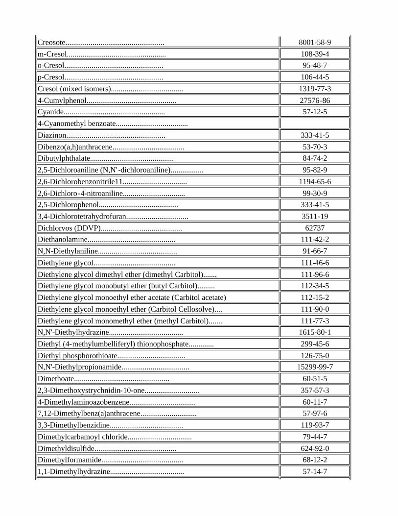
Creosote................................................... 8001-58-9
m-Cresol................................................... 108-39-4 o-Cresol................................................... 95-48-7
p-Cresol................................................... 106-44-5
Cresol (mixed isomers)..................................... 1319-77-3
4-Cumylphenol.............................................. 27576-86 Cyanide.................................................... 57-12-5
4-Cyanomethyl benzoate.....................................
Diazinon................................................... 333-41-5
Dibenzo(a,h)anthracene..................................... 53-70-3 Dibutylphthalate........................................... 84-74-2
2,5-Dichloroaniline (N,N' -dichloroaniline)................. 95-82-9
2,6-Dichlorobenzonitrile11................................. 1194-65-6
2,6-Dichloro-4-nitroaniline................................ 99-30-9 2,5-Dichlorophenol......................................... 333-41-5
3,4-Dichlorotetrahydrofuran................................ 3511-19
Dichlorvos (DDVP).......................................... 62737 Diethanolamine............................................. 111-42-2
N,N-Diethylaniline......................................... 91-66-7
Diethylene glycol.......................................... 111-46-6
Diethylene glycol dimethyl ether (dimethyl Carbitol)....... 111-96-6 Diethylene glycol monobutyl ether (butyl Carbitol)......... 112-34-5
Diethylene glycol monoethyl ether acetate (Carbitol acetate) 112-15-2
Diethylene glycol monoethyl ether (Carbitol Cellosolve).... 111-90-0
Diethylene glycol monomethyl ether (methyl Carbitol)....... 111-77-3 N,N'-Diethylhydrazine...................................... 1615-80-1
Diethyl (4-methylumbelliferyl) thionophosphate............. 299-45-6
Diethyl phosphorothioate................................... 126-75-0 N,N'-Diethylpropionamide................................... 15299-99-7
Dimethoate................................................. 60-51-5
2,3-Dimethoxystrychnidin-10-one............................ 357-57-3
4-Dimethylaminoazobenzene.................................. 60-11-7 7,12-Dimethylbenz(a)anthracene............................. 57-97-6
3,3-Dimethylbenzidine...................................... 119-93-7
Dimethylcarbamoyl chloride................................. 79-44-7
Dimethyldisulfide.......................................... 624-92-0 Dimethylformamide.......................................... 68-12-2
1,1-Dimethylhydrazine...................................... 57-14-7

Dimethylphthalate.......................................... 131-11-3
Dimethylsulfone............................................ 67-71-0 Dimethylsulfoxide.......................................... 67-68-5
4,6-Dinitro-o-cresol....................................... 534-52-1
1,2-Diphenylhydrazine...................................... 122-66-7
Dipropylene glycol (1,1'-oxydi-2-propanol)................. 110-98-5 Endrin..................................................... 72-20-8
Epinephrine................................................ 51-43-4
mono-Ethanolamine.......................................... 141-43-5
Ethyl carbamate (urethane)................................. 5-17-96 Ethylene glycol............................................ 107-21-1
Ethylene glycol monobutyl ether (butyl Cellosolve)......... 111-76-2
Ethylene glycol monoethyl ether (Cellosolve)............... 110-80-5
Ethylene glycol monoethyl ether acetate (Cellosolve acetate) 111-15-9 Ethylene glycol monomethyl ether (methyl Cellosolve)....... 109-86-4
Ethylene glycol monophenyl ether (phenyl Cellosolve)....... 122-99-6
Ethylene glycol monopropyl ether (propyl Cellosolve)....... 2807-30-9 Ethylene thiourea (2-imidazolidinethione).................. 9-64-57
4-Ethylmorpholine.......................................... 100-74-3
3-Ethylphenol.............................................. 620-17-7
Fluoroacetic acid, sodium salt............................. 62-74-8 Formaldehyde............................................... 50-00-0
Formamide.................................................. 75-12-7
Formic acid................................................ 64-18-6
Fumaric acid............................................... 110-17-8 Glutaric acid.............................................. 110-94-1
Glycerin (Glycerol)........................................ 56-81-5
Glycidol................................................... 556-52-5 Glycinamide................................................ 598-41-4
Glyphosate................................................. 1071-83-6
Guthion.................................................... 86-50-0
Hexamethylene-1,6-diisocyanate (1,6-diisocyanatohexane).... 822-06-0 Hexamethyl phosphoramide................................... 680-31-9
Hexanoic acid.............................................. 142-62-1
Hydrazine.................................................. 302-01-2
Hydrocyanic acid........................................... 74-90-8 Hydroquinone............................................... 123-31-9
Hydroxy-2-propionitrile (hydracrylonitrile)................ 109-78-4

Indeno (1,2,3-cd) pyrene................................... 193-39-5
Lead acetate............................................... 301-04-2 Lead subacetate (lead acetate, monobasic).................. 1335-32-6
Leucine.................................................... 61-90-5
Malathion.................................................. 121-75-5
Maleic acid................................................ 110-16-7 Maleic anhydride........................................... 108-31-6
Mesityl oxide.............................................. 141-79-7
Methane sulfonic acid...................................... 75-75-2
Methomyl................................................... 16752-77-5 p-Methoxyphenol............................................ 150-76-5
Methyl acrylate............................................ 96-33-3
4,4'-Methylene-bis-(2-chloroaniline)....................... 101-14-4
4,4'-Methylenediphenyl diisocyanate (diphenyl methane diisocyanate)..............................................
101-68-8
4,4'-Methylenedianiline.................................... 101-77-9
Methylene diphenylamine (MDA)..............................5-Methylfurfural........................................... 620-02-0
Methylhydrazine............................................ 60-34-4
Methyliminoacetic acid.....................................
Methyl methane sulfonate................................... 66-27-3 1-Methyl -2-methoxyaziridine................................
Methylparathion............................................ 298-00-0
Methyl sulfuric acid (sulfuric acid, dimethyl ester)....... 77-78-1
4-Methylthiophenol......................................... 106-45-6 Monomethylformamide (N-methylformamide).................... 123-39-7
Nabam...................................................... 142-59-6
alpha-Naphthol............................................. 90-15-3 beta-Naphthol.............................................. 135-19-3
alpha-Naphthylamine........................................ 134-32-7
beta-Naphthylamine......................................... 91-59-8
Neopentyl glycol (dimethylolpropane)....................... 126-30-7 Niacinamide................................................ 98-92-0
o-Nitroaniline............................................. 88-74-4
Nitroglycerin.............................................. 55-63-0
2-Nitrophenol.............................................. 88-75-5 4-Nitrophenol.............................................. 100-02-7
N-Nitrosodimethylamine..................................... 62-75-9

Nitrosoguanidine........................................... 674-81-7
N-Nitroso-n-methylurea..................................... 684-93-5 N-Nitrosomorpholine (4-nitrosomorpholine).................. 59-89-2
Oxalic acid................................................ 144-62-7
Parathion.................................................. 56-38-2
Pentaerythritol............................................ 115-77-5 Phenacetin................................................. 62-44-2
Phenol..................................................... 108-95-2
Phenylacetic acid.......................................... 103-82-2
m-Phenylene diamine........................................ 108-45-2 o-Phenylene diamine........................................ 95-54-5
p-Phenylene diamine........................................ 106-50-3
Phenyl mercuric acetate.................................... 62-38-4
Phorate.................................................... 298-02-2 Phthalic anhydride......................................... 85-44-9
alpha-Picoline (2-methyl pyridine)......................... 109-06-8
1,3-Propane sulfone........................................ 1120-71-4 beta-Propiolactone......................................... 57-57-8
Proporur (Baygon)..........................................
Propylene glycol........................................... 57-55-6
Pyrene..................................................... 129-00-0 Pyridinium bromide......................................... 39416-48-3
Quinoline.................................................. 91-22-5
Quinone (p-benzoquinone)................................... 106-51-4
Resorcinol................................................. 108-46-3 Simazine................................................... 122-34-9
Sodium acetate............................................. 127-09-3
Sodium formate............................................. 141-53-7 Strychnine................................................. 57-24-9
Succinic acid.............................................. 110-15-6
Succinimide................................................ 123-56-8
Sulfanilic acid............................................ 121-47-1 Terephthalic acid.......................................... 100-21-0
Tetraethyldithiopyrophosphate.............................. 3689-24-5
Tetraethylenepentamine..................................... 112-57-2
Thiofanox.................................................. 39196-18-4 Thiosemicarbazide.......................................... 79-19-6
2,4-Toluenediamine......................................... 95-80-7
Enabling Legislation: Neb. Rev. Stat. §81-1505(13) Legal Citation: Title 128, Chapter 26, Nebraska Department of Environmental Quality
For more information, contact [email protected]
Nebraska Department of Environmental Quality
1200 "N" Street, Suite 400 PO Box 98922
Lincoln, NE 68509 (402)471-2186 fax: (402)471-2909
2,6-Toluenediamine......................................... 823-40-5
3,4-Toluenediamine......................................... 496-72-0 2,4-Toluene diisocyanate................................... 584-84-9
p-Toluic acid.............................................. 99-94-5
m-Toluidine................................................ 108-44-1
1,1,2-Trichloro-1,2,2-trifluoroethane...................... 76-13-1 Triethanolamine............................................ 102-71-6
Triethylene glycol dimethyl ether..........................
Tripropylene glycol........................................ 24800-44-0
Warfarin................................................... 81-81-2 3,4-Xylenol (3,4-dimethylphenol)........................... 95-65-8