time-resolved vacuum rabi oscillations in a quantum dot ... file2institute of nano quantum...
TRANSCRIPT

1
Time-resolved vacuum Rabi oscillations in a quantum dot-nanocavity system
K. Kuruma1, Y. Ota2, M. Kakuda2, S. Iwamoto1,2 and Y. Arakawa1,2 1Institute of Industrial Science, The University of Tokyo, 4-6-1 Komaba, Meguro-ku,
Tokyo 153-8904, Japan 2Institute of Nano Quantum Information Electronics, The University of Tokyo, 4-6-1
Komaba, Meguro-ku, Tokyo 153-8904, Japan
We report time-domain observation of vacuum Rabi oscillations in a single quantum
dot strongly coupled to a nanocavity under incoherent optical carrier injection. We realize
a photonic crystal nanocavity with a very high quality factor of >80,000 and employ it to
clearly resolve the ultrafast vacuum Rabi oscillations by simple photoluminescence-based
experiments. We found that the time-domain vacuum Rabi oscillations were largely
modified when changing the pump wavelength and intensity, even when marginal
changes were detected in the corresponding photoluminescence spectra. We analyze the
measured time-domain oscillations by fitting to simulation curves obtained with a cavity
quantum electrodynamics model. The observed modifications of the oscillation curves
were mainly induced by the change in the carrier capture and dephasing dynamics in the
quantum dot, as well as the change in bare-cavity emission. This result suggests that
vacuum Rabi oscillations can be utilized as a highly sensitive probe for the quantum dot
dynamics. Our work points out a powerful alternative to conventional spectral-domain
measurements for a deeper understanding of the vacuum Rabi dynamics in quantum
dot-based cavity quantum electrodynamics systems.

2
I. INTRODUCTION
Semiconductor nanostructures coupled to optical resonators are a fascinating platform
for studying solid-state cavity quantum electrodynamics (CQED)[1,2]. In particular,
CQED systems based on quantum dots (QDs) and photonic crystal (PhC) nanocavities
are some of the most advanced systems, due to their strong light-matter interactions
originating from the tight optical confinement of the nanocavities both in time and space.
Since the first demonstration of strong coupling in QD-CQED[3,4], the coherent light
matter interactions have been employed for developing various classical and quantum
optical devices including optical switches[5–7], non-classical light generators[8,9] and
quantum gates[10].
Meanwhile, tremendous effort has been devoted to understanding the physics of
strongly coupled QD-CQED systems. Most of such studies were carried out by
measuring photoluminescence (PL) spectra under incoherent optical carrier injection.
The coupling strength in a QD-CQED system can be quickly characterized by
measuring its vacuum Rabi splitting[3,4,11–13]. Moreover, the PL-based experiments
have been widely employed for studying various intriguing phenomena such as triplet
vacuum Rabi spectra[14–17], off-resonant cavity-QD coupling[14,18–21],
phonon-QD-cavity coupling[22,23] and pump-induced dephasing[24]. However, the
spectral domain approach often encounters the difficulty in resolving the effect of slow
dynamics, which only slightly modifies the spectrum and is likely to be overlooked due
to the limitation in spectrometer resolution.
For investigating the dynamics in strongly-coupled QD-CQED systems, time domain
spectroscopy is the most straightforward approach. Previous studies have employed
ultrafast spectroscopy techniques using cavity-resonant optical pulses and succeeded in
resolving vacuum Rabi oscillations in QD-CQED systems[25,26]. However, the
observed oscillations were highly dissipative due to fast photon leakage from the
resonators and were recorded with rather limited signal to noise ratios, making them
unsuitable for analyzing slow dynamics in the CQED systems.
In this work, we report time domain observation of vacuum Rabi oscillations in a QD
strongly coupled to a PhC nanocavity under optical carrier injection. We realized a PhC
nanocavity with a very high experimental quality (Q) factor of > 80,000, enabling the
observation of remarkably coherent vacuum Rabi oscillations by conventional
time-correlated single photon counting (TCSPC). We utilized the observed vacuum Rabi
oscillations for probing the inner workings of the QD-CQED system in conjunction
with curve fitting using a theoretical CQED model. The sensitive responses of vacuum

3
Rabi oscillations to the QD dynamics facilitate the detection of slow pump-induced
dephasing in the QD, which was not resolved by our spectrometer. We also observed
that the carrier capture process in the QD largely depends on pump laser wavelength.
We believe that our approach based on PL spectroscopy will advance the understanding
of the dynamics in QD-CQED systems driven by carrier injection and thus be of
importance for various electrically-pumped QD-based CQED devices[27–32].
II. SAMPLE STRUCTURE AND EXPERIMENTAL SETUP
In this study, we used a GaAs-based PhC double-heterostructure cavity[33] with a
lattice constant of a1 = 252 nm and an air-hole radius of r = 61 nm. The lattice constant
of the central hetero region (a2) is slightly elongated to be 259.6 nm, forming an optical
mode gap to support nanocavity modes. Figure 1(a) exhibits an electric field profile for
the fundamental cavity mode calculated by a finite-difference time-domain algorithm.
This cavity mode confines light with a Q factor of ~3×10⁵ and a mode volume of
1.5(λ/n)3, where λ (= 3.875a) and n (= 3.46) are the cavity resonant wavelength and the
refractive index of GaAs, respectively. The designed cavity was fabricated into a 130
nm-thick GaAs slab on top of a 1-μm-thick Al0.7Ga0.3As sacrificial layer, which is later
dissolved to form an airbridge structure. The GaAs slab contains a single layer of low
density InAs QDs at the middle. Figure 1(b) shows a scanning electron microscope
(SEM) image of a fabricated cavity.
For optical characterizations, we performed micro photoluminescence (µPL)
measurements in both spectral and time domain using an optical setup illustrated
schematically in Fig. 1(b). The PhC sample was kept in a helium flow cryostat at
cryogenic temperatures (4-10 K). We used an 808-nm continuous wave (CW) diode
laser for the above-bandgap excitation of the GaAs barrier around the InAs QDs. We
also employed a CW wavelength-tunable laser for PL excitation (PLE) measurements.
For time domain measurements, we employed a Ti:sapphire pulse laser with a pulse
duration of 1 ps and a repetition rate of 80 MHz. We focused the pump laser light onto
the PhC cavities by an objective lens (OL) with a numerical aperture of 0.65. PL signals
from the sample were spectrally resolved by a spectrometer and subsequently detected
with a Si CCD camera. The spectrometer resolution was experimentally measured to be
21 μeV. During PL measurements, we precisely controlled the cavity resonant energy
using a Xe gas condensation technique[34]. For time-resolved PL experiments, we used
a TCSPC (Becker & Hickl Corp.) system equipped with a fast-response
superconducting single photon detector (SSPD, SCONTEL Corp.). We used the

4
spectrometer as a spectral bandpass filter (bandwidth = 180 μeV) for PL signals before
being sent to the SSPD. The total time resolution of the setup was measured to be 25.6
ps.
III. BASIC OPTICAL CHARACTERIZATION
First, we characterized the target QD-cavity system at 10 K. Figure 1(c) shows a bare
cavity spectrum measured under an excitation power of 7 nW (measured before the OL).
By fitting the spectrum with a Voigt peak function with a fixed Gaussian part
representing the spectrometer response, we obtained a high cavity Q factor of 81,000
(corresponding to a cavity decay rate κ = 16 μeV). This Q factor is, to the best of our
knowledge, the highest value reported to date for any PhC nanocavity employed for
QD-CQED studies.
Next, we investigated the optical coupling properties between the cavity mode and a QD
exciton transition peak at 1.31395 eV. Figure 2(a) shows a summary of PL spectra taken
by tuning the cavity mode resonance across the QD transition. Near the QD-cavity
resonance, an anti-crossing behavior was observed, suggesting that the QD-cavity
system is in strong coupling regime. From the peak split, we deduced a vacuum Rabi
splitting of 35 μeV, which can be translated into a coupling strength (g) of 18 μeV.
Figure 2(b) shows an on-resonance spectrum, composed of two polariton peaks and an
additional center peak. The center peak is of the bare cavity mode emission[14], which
occurs when transition peaks of the QD are off resonant from the cavity resonance and
is likely to be predominantly supplied by unspecified background emission in the
sample[16].
For characterizing absorption levels in the investigated QD, we performed PLE
measurements[35] at 7 K by using the tunable laser with an excitation power of 160 μW.
Figure 2(c) and (d) respectively show a PL spectrum of the QD emission and a
corresponding PLE spectrum measured with various excitation laser detunings spanning
from 19.4 to 63.8 meV. In the PLE spectrum, we observed several sharp resonances
together with a broad background across the measurement range. We attributed the
sharp peaks to optical transitions involving higher energy levels in the QD and those
assisted by optical phonons. We consider that the continuous background predominantly
originates from the absorption tail of a wetting layer (WL) contacting with the QD.
5
IV. TIME-DOMAIN OBSERVATION OF VACUUM RABI OSCILLATIONS
A. Detuning dependence
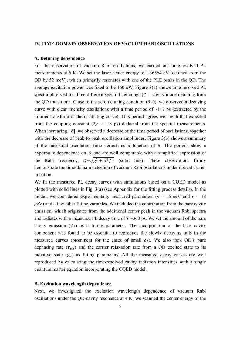
For the observation of vacuum Rabi oscillations, we carried out time-resolved PL
measurements at 6 K. We set the laser center energy to 1.36564 eV (detuned from the
QD by 52 meV), which primarily resonates with one of the PLE peaks in the QD. The
average excitation power was fixed to be 160 μW. Figure 3(a) shows time-resolved PL
spectra observed for three different spectral detunings ( = cavity mode detuning from
the QD transition). Close to the zero detuning condition ( ~0), we observed a decaying
curve with clear intensity oscillations with a time period of ~117 ps (extracted by the
Fourier transform of the oscillating curve). This period agrees well with that expected
from the coupling constant (2g ~ 118 ps) deduced from the spectral measurements.
When increasing | |, we observed a decrease of the time period of oscillations, together
with the decrease of peak-to-peak oscillation amplitudes. Figure 3(b) shows a summary
of the measured oscillation time periods as a function of . The periods show a
hyperbolic dependence on and are well comparable with a simplified expression of
the Rabi frequency, Ω~ g2 4⁄ (solid line). These observations firmly
demonstrate the time-domain detection of vacuum Rabi oscillations under optical carrier
injection.
We fit the measured PL decay curves with simulations based on a CQED model as
plotted with solid lines in Fig. 3(a) (see Appendix for the fitting process details). In the
model, we considered experimentally measured parameters (κ = 16 μeV and g = 18
μeV) and a few other fitting variables. We included the contribution from the bare cavity
emission, which originates from the additional center peak in the vacuum Rabi spectra
and radiates with a measured PL decay time of T ~360 ps. We set the amount of the bare
cavity emission ( ) as a fitting parameter. The incorporation of the bare cavity
component was found to be essential to reproduce the slowly decaying tails in the
measured curves (prominent for the cases of small s). We also took QD’s pure
dephasing rate ( ) and the carrier relaxation rate from a QD excited state to its
radiative state ( ) as fitting parameters. All the measured decay curves are well
reproduced by calculating the time-resolved cavity radiation intensities with a single
quantum master equation incorporating the CQED model.
B. Excitation wavelength dependence
Next, we investigated the excitation wavelength dependence of vacuum Rabi
oscillations under the QD-cavity resonance at 4 K. We scanned the center energy of the

6
pulsed laser source from 1.53465 eV (above the GaAs band gap) to 1.33621 eV (21
meV above the QD exciton line). In the current measurements performed in a later day
than that for Fig. 3, the cavity Q factor was slightly degraded to be 71,000 (κ = 19 μeV),
probably due to unspecified surface contamination. Figure 4(a) shows time-resolved PL
spectra measured with different laser center frequencies. For each point of the
measurements, we varied pump laser power so as to keep the same photon count rate on
the SSPD. We observed clear modifications of the measured time-resolved curves: the
Rabi oscillations become clearer with decreasing excitation energy. Concomitantly, the
measured curves become more likely to decay faster, suggesting a reduction of the slow
decay component originating from the bare cavity mode emission. We also found faster
initial rises of the emission intensity when using lower energy excitations, as
summarized in Fig. 4(b). In contrast, despite these large modifications in the time
resolved spectra, we did not observe significant changes in the corresponding PL spectra,
as plotted in Fig. 4(c). This comparison accentuates the usefulness of the time-domain
spectroscopy for studying QD-based CQED.
We analyzed the measured PL decay curves by comparing with the CQED model in
terms of its main fitting parameters ( , , ). In Fig. 4(a), we overlaid the fitting
curves (solid lines) on the measured curves. Through the fitting process, we deduced the
values for , and , which are respectively summarized in Figs. 4(d), (e) and (f).
The values of are normalized to that measured by the above bandgap excitation. In
Fig. 4(d), we found a tendency of faster carrier relaxation for lower excitation energies,
which can also be confirmed by the sharper initial intensity rises in Fig. 4(b). A steep
increase of occurs when the laser detuning becomes less than 70 meV, roughly
corresponding to the lower energy edge of the WL absorption peak. Under such low
energy excitations, carriers are tend to be directly injected into the QD, eliminating the
time of carrier diffusion in the surrounding material before the carrier capture and hence
resulting in a faster . The monotonic increase of s with decreasing laser energy
may be understood as a result of a gradual increase of the contribution of the faster
direct carrier capture process.
We also observed a monotonic decrease of when reducing laser detunings below 70
meV, as shown in Fig. 4(e). It is known that excess carriers within the barrier material
can turn into background emission uncorrelated with the QD, which, we assume, is a
primary source for the bare cavity mode emission. Supposing as an indicator of
excess carriers in the surrounding material, its reduction for lower laser frequencies
consistently explains the accompanied increase of by the reduced indirect carrier
capture processes through the surroundings. The evolution of deduced s is

7
summarized in Fig. 4(f), showing a nearly-monotonic increase for higher laser
frequencies. Again, this observation can be attributed to an increase of the excess
carriers within the surrounding material, the fluctuation of which is known to induce
pure dephasing in the QD[36,37]. It is noteworthy that we extracted of only a few
μeV by fitting to the time domain vacuum Rabi oscillations. Such small pure dephasing
is in general difficult to resolve by spectral domain PL measurements, highlighting the
usefulness of the time-domain approach for understanding the slow dynamics in QD-
CQED.
C. Excitation power dependence
Finally, we investigated the excitation power dependence of the vacuum Rabi oscillation
under the QD-cavity resonance with 1.33909 eV pumping (25 meV above the QD
transition). Figure 5(a) displays time-resolved PL spectra measured for three different
excitation powers of 10, 113 and 300 μW. As the pump power increases, the Rabi
oscillation becomes blurred and the time resolved PL curve acquires more slow decay
component. The increase of the slow component is again attributed to an increase of the
bare cavity mode emission, which is also indicated by the slightly reduced center dips in
the corresponding vacuum Rabi spectra shown in Fig. 5(b).
Using the same fitting procedure, we again estimated the values of the main fitting
parameters ( , , ) for different pump powers. Figure 5(c) shows the deduced
s as a function of average pump power. s are found to be nearly constant around a
very fast value of ~38 μeV (58 GHz), which can be thought of as a result of the
dominant direct carrier injection into the QD. Meanwhile, as seen in Fig. 5(d), we
observed a clear increase of the bare cavity emission for stronger laser pump,
suggesting an increase of excess carriers in the surroundings. We consider that, in the
current experiments, the laser energy is very low and thus the excess carriers are mainly
generated in deep trap levels of the barrier materials. As such, they cannot efficiently
diffuse to be captured by the QD and thereby do not significantly alter . Consistent
with the increase of , we observed an increase of from 2.6 μeV (3.9 GHz) to 6.4
μeV (9.7 GHz) when using stronger pump powers, as depicted in Fig. 5(e). We consider
that the monotonic increase of directly reflects the effect of pump-induced
dephasing[24,36,37]. Again, the extracted rate of the pump-induced dephasing at
minimum is only a few μeV, which is much smaller than our spectrometer resolution,
suggesting the advantages of time-domain measurements for discussing the slow QD
dynamics.

8
V. CONCLUSION
In conclusion, we demonstrated the time-domain observation of vacuum Rabi
oscillations in a strongly coupled QD-PhC cavity system driven under incoherent optical
carrier injection. We utilized a high Q (=81,000) PhC nanocavity and observed clear
vacuum Rabi oscillations by simple PL-based experiments using a TCSPC system. We
further performed the time-domain experiments with varying the excitation wavelength
and power. We found that the vacuum Rabi oscillation profiles largely change even when
the corresponding PL spectra did not change significantly. We analyzed the measured
oscillation curves by fitting to a theoretical CQED model. We concluded that the observed
modifications in the time-domain oscillation curves originate from the dephasing and
carrier capture process in the QD, as well as change in the bare cavity emission intensity.
These findings suggest that the vacuum Rabi oscillations can be used for a highly
sensitive probe for the dynamics in QDs. Our study also will be a great help for quantum
optical applications based on vacuum Rabi oscillations[38] as well as for QD-CQED
devices driven by carrier injection .
ACKNOWLEDGMENTS
We would like to thank M. Nishioka, S. Ishida and C. F. Fong for their technical support
and fruitful discussions. This work was supported by Japan society for the Promotion of
Science (JSAP) Grants-in-Aid for Specially Promoted Research (KAKENHI) No.
15H05700 and the New Energy and Industrial Technology Development Organization
(NEDO) project.

9
APPENDIX: THEORETICAL MODEL
We fitted the experimentally-observed vacuum Rabi oscillations using
numerically-calculated PL decay curves. In the simulation model, we consider a
three-level ladder-type quantum system for describing a QD. The radiative transition
between the middle (|E ) and the lowest (| ) energy levels is assumed to coherently
couple to a single cavity mode with a rate of g. The top energy level (|U ) and its
incoherent relaxation to |E are introduced for discussing the carrier capture process. The
Hamiltonian of this system under the dipole and rotating-wave approximation is given by
∑ ,U, , g , . . (1)
and are the frequency of the QD state |i and of the cavity mode, respectively.
, |i | is a pseudo spin operator, while and are the creation and annihilation
operator for cavity photons, respectively. In an appropriate rotating frame, the
Hamiltonian can be rewritten as
g , . . (2)
,where . In the model, we also treat several incoherent processes
including cavity photon leakage (at a rate of ), emitter’s spontaneous emission ( ),
incoherent state relaxation from |E to | ( ), incoherent state pumping from | to
|U ( ) and emitter pure dephasing ( ). Then, we obtain a quantum master equation as
follows,
, ′ (3)
,where is the density operator for the QD-cavity system and is the Lindblad
superoperator defined as:
2 2 , , , , , ,
2 , , , , , , 2 , , , ,
, , (4)
where, = |E | |G G| . For the incoherent pumping, we introduced a
Gaussian-shaped pulsed pumping: P = P0/ √2 exp(-(t-t0)2/2τ2). Here, P0 describes the

10
amplitude of the incoherent pumping, which was kept low enough for appropriately
describing the actual experiments. t0 and respectively determine the timing of the pulse
irradiation and pulse duration. We set the full width at half maximum (FWHM) of the
pulse τFWHM ( ×2√2ln2) to be 1 ps. We treated g, and as fixed parameters. We
employed experimentally obtained values for the first two parameters. For , we used a
typical value of 0.13μeV for our QD-cavity systems[39]. We solved the master equation
in the time domain based on the Runge–Kutta method, after truncating the cavity photon
Hilbert space at the single photon Fock state. From the simulated density matrix, we
calculated time evolutions of cavity photon number. We then added the contribution of
slowly-decaying bare cavity mode emission expressed as a single exponential function:
exp(-t/T) + y0. The resulting cavity emission curves were then used for fitting after
being convolved with a peak function reflecting the detection system time response (25.6
ps). For the fitting, we treated the amplitude of the slow component ( ) and the constant
offset (y0) as fitting parameters. The decay time constant (T) are measured to be ~360 ps
by measuring cavity mode emission under a far off-resonant condition. All the fitting
variables (∆, , , and y0) are deduced by fitting the experimental data with
theoretical curves based on a least squares method using a trust-region-reflective
algorithm (included in the Optimization Toolbox, MATLAB, The MathWorks).

11
Fig. 1. (a) Simulated electric field profile of the investigated double-heterostructure
cavity. The back dashed lines indicate the interfaces between the regular PhCs with a
lattice constant of a1 = 252 nm and the hetero region with a2 = 259.6 nm. (b) Top view
SEM image of a fabricated cavity. The white dash lines indicate the hetero interfaces.
(c) Schematic of the µPL measurement setup. M: mirror, FM: flip mirror, OL: objective
lens, BS: beam splitter. (d) PL spectrum for the fundamental cavity mode measured
under a far-detuned condition. Red solid line is of a fitting curve with a Voigt peak
function, the Gaussian part of which corresponds to the spectrometer response.

12
Fig. 2. (a) Color map of PL spectra measured under various QD-cavity detunings. (b)
Vacuum Rabi spectrum measured at the QD-cavity resonance. The solid red line is of
the fitting result by multiple Voigt peak functions. The light green lines show each
component of the fitting function. The center peak between the two polariton peaks
originates from the bare cavity emission. (c) PL spectrum of the investigated QD
emitting at 1.31395 eV. (d) PLE spectrum for the QD PL peak in (c), exhibiting sharp
PLE peaks and a broad non-zero background.

13
Fig. 3. (a) Time-resolved PL spectra measured at a laser excitation energy of 1.36564
eV under three-different QD-cavity spectral detunings of -55 μeV (black), -33 μeV
(light green) and ~ 0 μeV (blue). Each decay curve is smoothed out by applying a
moving average. The black arrows indicate peak positions of the oscillations. The red
lines show the fitting curves. (b) Measured Rabi frequencies (Ω) plotted as a function of
QD-cavity spectral detuning . The solid black line shows calculated Ωs using a simple
CQED model.
0 100 200 300 400 500
10-1
100
101
Inte
nsit
y (a
.u.)
Time (ps)-90 -60 -30 0 30 60 90
15
20
25
30
35
40
Rab
i Fre
qu
ency
(e
V)
Spectral Detuning (eV)
δ = -55 μeV
δ = -33 μeV
δ ~ 0 μeV
(a) (b)

14
Fig. 4. (a) PL decay curves measured with varying the center energy of the pump laser.
The QD and the cavity mode are under the resonance. The four curves are measured
with various relative excitation energies: the black curve is for the excitation energy of
221 meV above the QD (above the GaAs bandgap), dark green for 52 meV, light green
for 41 meV and blue for 25 meV. The solid red lines are the fitting curves. (b) Enlarged
views for resolving the initial rises of time-domain PL curves corresponding to (a). (c)
Corresponding vacuum Rabi spectra to (a) measured at the QD-cavity resonance. The
red lines show the fitting curves. Slight shifts of the peak positions arise from the QD
energy shifts under the different excitation conditions. (d) Extracted carrier relaxation
rates s, (e) the intensities of the bare cavity emission s and (f) pure dephasing
rates s plotted as a function of the relative excitation energies. s are normalized
to that measured under the above-bandgap excitation with the relative excitation energy
of 221 meV. These data points were obtained by experiments performed under the
conditions of keeping the same photon count rate on the SSPD by tuning the excitation
power (between 100 nW and 140 μW).
0 50 100 150 200 2500.0
0.5
1.0
1.5
Nor
mal
ized
Ai
Relative Energy (meV)
0 50 100 150 2000.0
1.0
Nor
m. I
nte
nsi
ty (
a.u
.)Time (ps)
25 meV
52 meV
41 meV
Above band
0 50 100 150 200 250
2
4
6
8
10
12
ph (e
V)
Relative Energy (meV)0 50 100 150 200 250
10
20
30
40
50
R (e
V)
Relative Energy (meV)
0 200 400 600
10-2
10-1
100
101
Inte
nsi
ty (
a.u
.)
Time (ps)1.31391 1.31400 1.31409
0.0
1.0
2.0
3.0
4.0
Nor
m. I
nte
nsi
ty (
a.u
.)
Energy (eV)
(a)
25 meV
52 meV
41 meV
Above band
(e)
25 meV
52 meV
Above band
41 meV
(b)
(d)
(c)
(f)

15
Fig. 5. (a) Time-resolved PL spectra measured at the QD-cavity resonance under the
excitation power of 10 μW (black), 113 μW (red) and 300 μW (green). The red solid
lines exhibit fitting results. (b) Corresponding PL spectra to (a), overlaid with fitting
curves (red lines). (c) Extracted carrier relaxation rates s, (d) the intensities of the
bare cavity emission s, and (e) pure dephasing rates s, plotted as a function of the
excitation power. s are plotted after normalized by that measured with a pump power
of 10 μW
0 50 100 150 200 250 300
1.0
3.0
5.0
7.0
Excitation Power (W)
Nor
mal
ized
Ai
0 50 100 150 200 250 30025
30
35
40
45
50
R (e
V)
Excitation Power (W)
(e)(c)
0 100 200 300 400 500
10-2
10-1
100
Inte
nsit
y (a
.u.)
Time (ps)1.31391 1.31400 1.31409
0.0
1.0
2.0
3.0
Nor
m. I
nten
sity
(a.
u.)
Energy (eV)
300 µW
113 µW
10 µW
(b)
300 µW
113 µW
10 µW
(a)
(d)
0 50 100 150 200 250 3002
3
4
5
6
7
ph (e
V)
Excitation Power (W)

16
REFERENCES
[1] C. Weisbuch, M. Nishioka, A. Ishikawa, and Y. Arakawa, Phys. Rev. Lett. 69, 3314
(1992).
[2] T.B. Norris, J.K. Rhee, C.Y. Sung, Y. Arakawa, M. Nishioka, and C. Weisbuch,
Phys. Rev. B 50, 14663 (1994).
[3] T. Yoshie, A. Scherer, J. Hendrickson, G. Khitrova, H.M. Gibbs, G. Rupper, C. Ell,
O.B. Shchekin, and D.G. Deppe, Nature 432, 200 (2004).
[4] J.P. Reithmaier, G. Sek, A. Löffler, C. Hofmann, S. Kuhn, S. Reitzenstein, L. V
Keldysh, V.D. Kulakovskii, T.L. Reinecke, and A. Forchel, Nature 432, 197 (2004).
[5] T. Volz, A. Reinhard, M. Winger, A. Badolato, K.J. Hennessy, E.L. Hu, and A.
Imamoglu, Nat Phot. 6, 605 (2012).
[6] D. Englund, A. Majumdar, M. Bajcsy, A. Faraon, P. Petroff, and J. Vučković, Phys.
Rev. Lett. 108, 093604 (2012).
[7] R. Bose, D. Sridharan, H. Kim, G.S. Solomon, and E. Waks, Phys. Rev. Lett. 108,
227402 (2012).
[8] A. Faraon, I. Fushman, D. Englund, N. Stoltz, P. Petroff, and J. Vučković, Nat. Phys.
4, 859 (2008).
[9] A. Reinhard, T. Volz, M. Winger, A. Badolato, K.J. Hennessy, E.L. Hu, and A.
Imamoğlu, Nat. Photonics 6, 93 (2011).
[10] H. Kim, R. Bose, T.C. Shen, G.S. Solomon, and E. Waks, Nat. Photonics 7, 373
(2013).
[11] Y. Arakawa, S. Iwamoto, M. Nomura, A. Tandaechanurat, and Y. Ota, IEEE J. Sel.
Top. Quantum Electron. 18, 1818 (2012).
[12] Y. Ota, R. Ohta, N. Kumagai, S. Iwamoto, and Y. Arakawa, Phys. Rev. Lett. 114,
143603 (2015).
17
[13] K. Kuruma, Y. Ota, M. Kakuda, D. Takamiya, S. Iwamoto, and Y. Arakawa, Appl.
Phys. Lett. 109, 071110 (2016).
[14] K. Hennessy, A. Badolato, M. Winger, D. Gerace, M. Atatüre, S. Gulde, S. Fält,
E.L. Hu, and A. Imamoğlu, Nature 445, 896 (2007).
[15] M. Winger, A. Badolato, K.J. Hennessy, E.L. Hu, and A. Imamoğlu, Phys. Rev.
Lett. 101, 226808 (2008).
[16] Y. Ota, N. Kumagai, S. Ohkouchi, M. Shirane, M. Nomura, S. Ishida, S. Iwamoto,
S. Yorozu, and Y. Arakawa, Appl. Phys. Express 2, 122301 (2009).
[17] Y. Ota, D. Takamiya, R. Ohta, H. Takagi, N. Kumagai, S. Iwamoto, and Y.
Arakawa, Appl. Phys. Lett. 112, 093101 (2018).
[18] D. Press, S. Götzinger, S. Reitzenstein, C. Hofmann, A. Löffler, M. Kamp, A.
Forchel, and Y. Yamamoto, Phys. Rev. Lett. 98, 117402 (2007).
[19] M. Kaniber, A. Laucht, A. Neumann, J.M. Villas-Bôas, M. Bichler, M.-C. Amann,
and J.J. Finley, Phys. Rev. B 77, 161303 (2008).
[20] J. Suffczyński, A. Dousse, K. Gauthron, A. Lemaître, I. Sagnes, L. Lanco, J. Bloch,
P. Voisin, and P. Senellart, Phys. Rev. Lett. 103, 027401 (2009).
[21] M. Winger, T. Volz, G. Tarel, S. Portolan, A. Badolato, K.J. Hennessy, E.L. Hu, A.
Beveratos, J. Finley, V. Savona, and A. Imamoğlu, Phys. Rev. Lett. 103, 207403
(2009).
[22] U. Hohenester, A. Laucht, M. Kaniber, N. Hauke, A. Neumann, A. Mohtashami, M.
Seliger, M. Bichler, and J.J. Finley, Phys. Rev. B 80, 201311 (2009).
[23] Y. Ota, S. Iwamoto, N. Kumagai, and Y. Arakawa, arXiv:0908.0788.
[24] A. Laucht, N. Hauke, J.M. Villas-Bôas, F. Hofbauer, G. Böhm, M. Kaniber, and J.J.
Finley, Phys. Rev. Lett. 103, 087405 (2009).
[25] J. Kasprzak, S. Reitzenstein, E. a Muljarov, C. Kistner, C. Schneider, M. Strauss, S.
Höfling, A. Forchel, and W. Langbein, Nat. Mater. 9, 304 (2010).

18
[26] A. Majumdar, D. Englund, M. Bajcsy, and J. Vučković, Phys. Rev. A 85, 033802
(2012).
[27] H.-G. Park, S.-H. Kim, S.-H. Kwon, Y.-G. Ju, J.-K. Yang, J.-H. Baek, S.-B. Kim,
and Y.-H. Lee, Science 305, 1444 (2004).
[28] B. Ellis, M. a. Mayer, G. Shambat, T. Sarmiento, J. Harris, E.E. Haller, and J.
Vučković, Nat. Photonics 5, 297 (2011).
[29] G. Shambat, B. Ellis, A. Majumdar, J. Petykiewicz, M. a. Mayer, T. Sarmiento, J.
Harris, E.E. Haller, and J. Vučković, Nat. Commun. 2, 539 (2011).
[30] A. Laucht, F. Hofbauer, N. Hauke, J. Angele, S. Stobbe, M. Kaniber, G. Böhm, P.
Lodahl, M.-C. Amann, and J.J. Finley, New J. Phys. 11, 023034 (2009).
[31] A. Faraon, A. Majumdar, H. Kim, P. Petroff, and J. Vučković, Phys. Rev. Lett. 104,
047402 (2010).
[32] C. Bentham, I.E. Itskevich, R.J. Coles, B. Royall, E. Clarke, J. O’Hara, N. Prtljaga,
a. M. Fox, M.S. Skolnick, and L.R. Wilson, Appl. Phys. Lett. 106, 221101 (2015).
[33] B.-S. Song, S. Noda, T. Asano, and Y. Akahane, Nat. Mater. 4, 207 (2005).
[34] S. Mosor, J. Hendrickson, B.C. Richards, J. Sweet, G. Khitrova, H.M. Gibbs, T.
Yoshie, A. Scherer, O.B. Shchekin, and D.G. Deppe, Appl. Phys. Lett. 87, 141105
(2005).
[35] Y. Toda, O. Moriwaki, M. Nishioka, and Y. Arakawa, Phys. Rev. Lett. 82, 4114
(1999).
[36] A. Berthelot, I. Favero, G. Cassabois, C. Voisin, C. Delalande, P. Roussignol, R.
Ferreira, and J.M. Gérard, Nat. Phys. 2, 759 (2006).
[37] I. Favero, A. Berthelot, G. Cassabois, C. Voisin, C. Delalande, P. Roussignol, R.
Ferreira, and J.M. Gérard, Phys. Rev. B 75, 073308 (2007).
[38] R. Bose, T. Cai, K.R. Choudhury, G.S. Solomon, and E. Waks, Nat. Photonics 8,
858 (2014).

19
[39] Y. Ota, S. Iwamoto, N. Kumagai, and Y. Arakawa, Phys. Rev. Lett. 107, 233602
(2011).