tia portal v11 and simatic comfort panel application ... & tools answers for industry. cover...
TRANSCRIPT
Applications & Tools
Answers for industry.
Cover
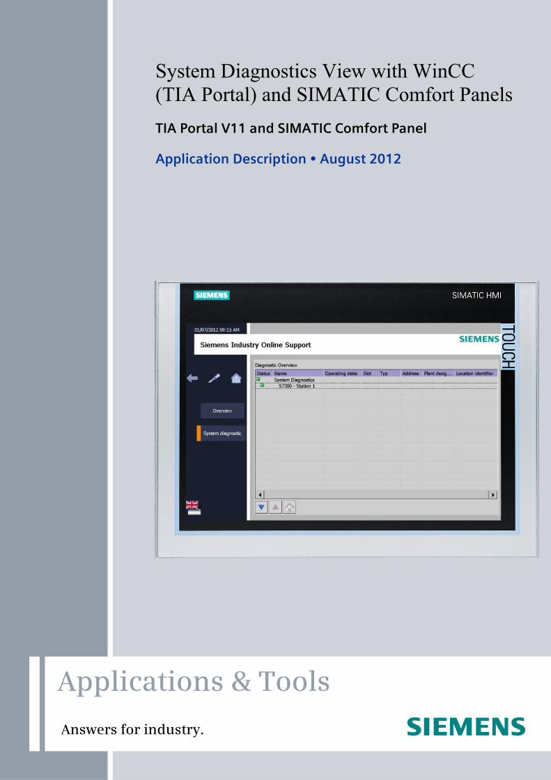
System Diagnostics View with WinCC (TIA Portal) and SIMATIC Comfort Panels
TIA Portal V11 and SIMATIC Comfort Panel
Application Description August 2012

2 System Diagnostics View with WinCC (TIA Portal) in SIMATIC Comfort Panels
V1.0, Entry ID: 61910954
Co
pyr
igh
t
Sie
me
ns
AG
20
12
All
righ
ts r
ese
rve
d
Siemens Industry Online Support
This document is taken from Siemens Industry Online Support. The following link takes you directly to the download page of this document:
http://support.automation.siemens.com/WW/view/en/61910954
Caution: The functions and solutions described in this entry are mainly limited to the realization of the automation task. In addition, please note that suitable security measures in compliance with the applicable Industrial Security standards must be taken if your system is interconnected with other parts of the plant, the company's network or the Internet. More information can be found under entry ID 50203404.
http://support.automation.siemens.com/WW/view/en/50203404
For further information on this topic, you may also actively use our Technical Forum in the Siemens Industry Online Support. Share your questions, suggestions or problems and discuss them with our strong forum community:
http://www.siemens.de/forum-applications
System Diagnostics View with WinCC (TIA Portal) in SIMATIC Comfort Panels V1.0, Entry ID: 61910954 3
Co
pyr
igh
t
Sie
me
ns
AG
20
12
All
righ
ts r
ese
rve
d
s
SIMATIC System Diagnostics View with WinCC (TIA Portal) in SIMATIC Comfort Panels
WinCC (TIA Portal), SIMATIC Comfort Panel
Task
1
Solution
2
Functional Mechanisms
3 Configuration and Settings in TIA Portal
4
Starting up the Application
5
Operation of the Application
6
Links & Literature
7
History
8
Warranty and Liability
4 System Diagnostics View with WinCC (TIA Portal) in SIMATIC Comfort Panels
V1.0, Entry ID: 61910954
Co
pyr
igh
t
Sie
me
ns
AG
20
12
All
righ
ts r
ese
rve
d
Warranty and Liability
Note The application examples are not binding and do not claim to be complete regarding configuration, equipment and any eventuality. The application examples do not represent customer-specific solutions. They are only intended to provide support for typical applications. You are responsible for ensuring that the described products are used correctly. These application examples do not relieve you of your responsibility to use sound practices in application, installation, operation and maintenance. When using these application examples, you recognize that we will not be liable for any damage/claims beyond the liability clause described. We reserve the right to make changes to these application examples at any time without prior notice. If there are any deviations between the recommendations provided in this application example and other Siemens publications (e.g. catalogs), the contents of the other documents shall have priority.
We do not accept any liability for the information contained in this document.
Any claims against us – based on whatever legal reason – resulting from the use of the examples, information, programs, engineering and performance data etc., described in this application example shall be excluded. Such an exclusion shall not apply in the case of mandatory liability, e.g. under the German Product Liability Act (“Produkthaftungsgesetz”), in case of intent, gross negligence, or injury of life, body or health, guarantee for the quality of a product, fraudulent concealment of a deficiency or violation of fundamental contractual obligations (“wesentliche Vertragspflichten”). The damages for a breach of a substantial contractual obligation are, however, limited to the foreseeable damage, typical for the type of contract, except in the event of intent or gross negligence or injury to life, body or health. The above provisions do not imply a change in the burden of proof to your detriment.
It is not permissible to transfer or copy these application examples or excerpts thereof without express authorization from Siemens Industry Sector.
Preface
System Diagnostics View with WinCC (TIA Portal) in SIMATIC Comfort Panels V1.0, Entry ID: 61910954 5
Co
pyr
igh
t
Sie
me
ns
AG
20
12
All
righ
ts r
ese
rve
d
Preface
Objective of this application
The objective of this application is to show you the principle of operation and the integration of the “System diagnostics view” Control in WinCC (TIA Portal). The application describes all the respective settings and configuration steps necessary.
Validity
The application is adjusted especially to WinCC (TIA Portal) in connection with the SIMATIC Comfort Panel and is based on the “WinCC Advanced V11.0 SP2” manual.
The implementation of the application additionally requires STEP 7 V11 Professional. You can also download the manuals on WinCC Advanced and STEP 7 V11 Professional under the following links:
WinCC_Advanced_V11_SP2 STEP 7 Professional V11.0 SP2
Table of Contents
6 System Diagnostics View with WinCC (TIA Portal) in SIMATIC Comfort Panels
V1.0, Entry ID: 61910954
Co
pyr
igh
t
Sie
me
ns
AG
20
12
All
righ
ts r
ese
rve
d
Table of Contents Warranty and Liability ................................................................................................. 4
Preface .......................................................................................................................... 5
1 Task..................................................................................................................... 7
2 Solution............................................................................................................... 8
2.1 Overview of the general solution.......................................................... 8 2.2 Description of the core functionality ................................................... 10 2.3 Hardware and software components used......................................... 13
3 Functional Mechanisms.................................................................................. 15
3.1 “System diagnostics view” Control ..................................................... 15 3.1.1 Device view ........................................................................................ 15 3.1.2 Details view ........................................................................................ 15 3.1.3 Matrix view ......................................................................................... 15 3.1.4 Contents of the diagnosis................................................................... 15 3.1.5 Symbols of the System diagnostics view ........................................... 16 3.2 Function of the diagnosis indicator..................................................... 16 3.3 Background on diagnostic capability.................................................. 17 3.3.1 Information on Pdiag .......................................................................... 17 3.3.2 Information on ProAgent .................................................................... 17 3.4 Data exchange ................................................................................... 18
4 Configuration and Settings in TIA Portal ...................................................... 19
4.1 Preparatory measures for the configuration....................................... 19 4.1.1 IP addresses ...................................................................................... 19 4.1.2 Addresses, parameters and passwords used.................................... 19 4.2 Configuration of CPU 315-2 PN/DP................................................... 20 4.3 Configuration of the SIMATIC Comfort Panel .................................... 24
5 Starting up the Application............................................................................. 28
5.1 Preparing measures ........................................................................... 28 5.2 Commissioning................................................................................... 28
6 Operation of the Application .......................................................................... 29
6.1.1 “000.0_Startscreen” screen................................................................ 29 6.1.2 “001.0_Overview” screen ................................................................... 30 6.1.3 “001.1_Thema_A” screen .................................................................. 31 6.1.4 “002.0_Support_Overview” screen .................................................... 32 6.1.5 “000.1_System” screen ...................................................................... 33
7 Links & Literature ............................................................................................ 34
7.1 Literature ............................................................................................ 34 7.2 Internet links ....................................................................................... 34
8 History............................................................................................................... 35
1 Task
System Diagnostics View with WinCC (TIA Portal) in SIMATIC Comfort Panels V1.0, Entry ID: 61910954 7
Co
pyr
igh
t
Sie
me
ns
AG
20
12
All
righ
ts r
ese
rve
d
1 Task
Introduction
In many areas of automation technology detailed diagnostic information of hardware states are helpful. Wherever quick error removals and quick restart of the plant are an advantage or necessary in particular, monitoring the automation hardware is recommended.
In this example, failures of the diagnostics-capable CPU and the connected I/O shall be displayed using standard mechanisms.
Overview of the automation task
The figure below provides an overview of the automation task.
Figure 1-1
Failure n
Automation Process
Warning or error case
Visualized SystemController 1
Controller 2Failure 2
Controller n
Failure 1
Failure
Description of the automation task
The aim of the automation task is to provide the operator or user with the diagnostic information of the automation module. The diagnostic information can help find the failure quicker and minimize the related downtimes.
2 Solution
2.1 Overview of the general solution
8 System Diagnostics View with WinCC (TIA Portal) in SIMATIC Comfort Panels
V1.0, Entry ID: 61910954
Co
pyr
igh
t
Sie
me
ns
AG
20
12
All
righ
ts r
ese
rve
d
2 Solution
2.1 Overview of the general solution
Schematic layout
This application was created with the following hardware:
• SIMATIC Comfort Panel
• Distributed I/O ET200S
• SIMATIC S7-300 Controller
• SCALANCE X208
The figure below shows the wiring of the solution:
Figure 2-1
System Diagnosis with WinCC Advanced and Comfort Panel
PE
NL
24V Power supply
SIMATIC Comfort Panel
ET200SCPU 315-2 PN/DP
SCALANCEX208Power supply
Ethernet
Structure
An SIMATIC Comfort Panel with connected automation devices (e.g. ET 200S, CPU 315-2 PN/DP) is located in an industrial plant.
To provide the operator with a diagnosis of the configured automation devices for quick error diagnosis, the “System diagnostics view” Control was configured in the SIMATIC Comfort Panel. This control provides the operator with detailed information of the configured automation devices.
2 Solution
2.1 Overview of the general solution
System Diagnostics View with WinCC (TIA Portal) in SIMATIC Comfort Panels V1.0, Entry ID: 61910954 9
Co
pyr
igh
t
Sie
me
ns
AG
20
12
All
righ
ts r
ese
rve
d
Advantages
The application on hand offers you the following advantages:
• Low configuration workload for realization in the own plant
• Implementation with TIA Portal standard tools
• Detailed description of the “control” to be implemented
• Description for evaluating the delivered diagnostic functions
This application significantly helps you safe time during configuration in the TIA Portal.
Topics not covered by this application
For a better overview, the application will only give information necessary for the reproduction of this example.
Where necessary, the document provides references to related links and manuals.
• This application does not include information on the following topics:
– “Safety notes and standards”
– “Directives and approvals”
– “Operational safety”, etc.
• This application does not include a description of the TIA Portal engineering tool.
• It only describes the settings of the used hardware and software components that are necessary for the application.
• This application does not discuss the STEP 7 Professional software in greater detail.
Basic knowledge of the topics listed above is assumed. For detailed information, please refer to the associated device manuals.
Assumed knowledge
Basic knowledge of the topics listed above is assumed. For detailed information, please refer to the associated “WinCC Advanced V11.0 SP2” and “STEP 7 Professional V11.0 SP2” device manuals.

2 Solution
2.2 Description of the core functionality
10 System Diagnostics View with WinCC (TIA Portal) in SIMATIC Comfort Panels
V1.0, Entry ID: 61910954
Co
pyr
igh
t
Sie
me
ns
AG
20
12
All
righ
ts r
ese
rve
d
2.2 Description of the core functionality
The core of this application is to show the user the procedure for configuring the “System diagnostics view” Control in WinCC (TIA Portal).
When a configured automation device generates a diagnostic message due to a failure, this diagnostic message will be displayed in the configured “System diagnostics view” Control.
This control offers the user to precisely determine the location of the automation device from which the diagnostic message was generated. This saves the plant operator much time when localizing and removing the error.
What can the application perform?
The program example included contains
• An instruction for configuring the “System diagnostics view” Control and the connected automation devices.
• A WinCC (TIA Portal) project with the following components
– SIMATIC Comfort Panel for visualizing the system diagnostics messages
– STEP 7 Professional V11 program which contains the integrated automation hardware for generating the system diagnostics messages
You can use the program as a template for your applications.
Note The system diagnostic display is only available in connection with SIMATIC Comfort Panels.
2 Solution
2.2 Description of the core functionality
System Diagnostics View with WinCC (TIA Portal) in SIMATIC Comfort Panels V1.0, Entry ID: 61910954 11
Co
pyr
igh
t
Sie
me
ns
AG
20
12
All
righ
ts r
ese
rve
d
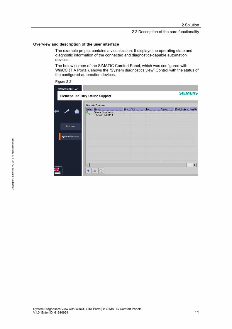
Overview and description of the user interface
The example project contains a visualization. It displays the operating state and diagnostic information of the connected and diagnostics-capable automation devices.
The below screen of the SIMATIC Comfort Panel, which was configured with WinCC (TIA Portal), shows the “System diagnostics view” Control with the status of the configured automation devices.
Figure 2-2
2 Solution
2.2 Description of the core functionality
12 System Diagnostics View with WinCC (TIA Portal) in SIMATIC Comfort Panels
V1.0, Entry ID: 61910954
Co
pyr
igh
t
Sie
me
ns
AG
20
12
All
righ
ts r
ese
rve
d
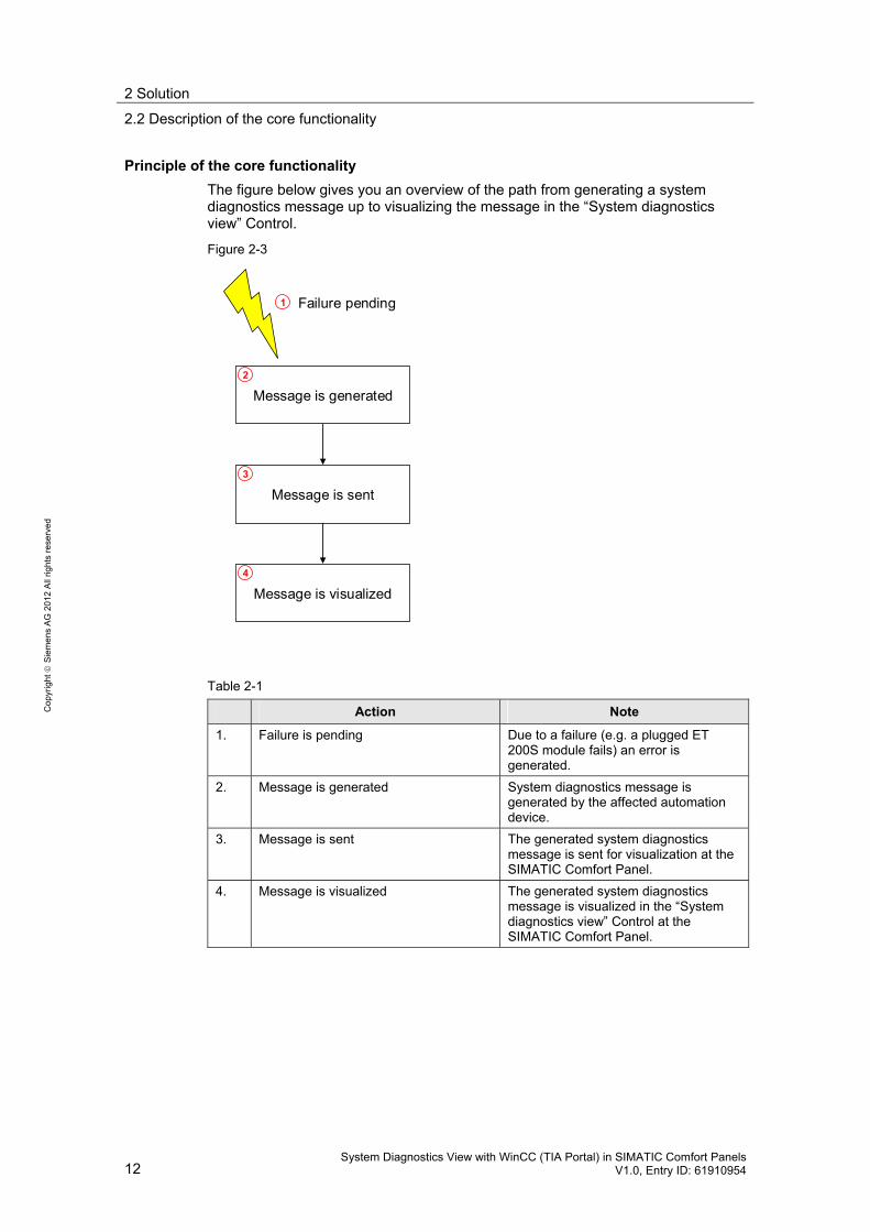
Principle of the core functionality
The figure below gives you an overview of the path from generating a system diagnostics message up to visualizing the message in the “System diagnostics view” Control.
Figure 2-3
Message is generated
Message is sent
Message is visualized
Failure pending1
2
3
4
Table 2-1
Action Note
1. Failure is pending Due to a failure (e.g. a plugged ET 200S module fails) an error is generated.
2. Message is generated System diagnostics message is generated by the affected automation device.
3. Message is sent The generated system diagnostics message is sent for visualization at the SIMATIC Comfort Panel.
4. Message is visualized The generated system diagnostics message is visualized in the “System diagnostics view” Control at the SIMATIC Comfort Panel.
2 Solution
2.3 Hardware and software components used
System Diagnostics View with WinCC (TIA Portal) in SIMATIC Comfort Panels V1.0, Entry ID: 61910954 13
Co
pyr
igh
t
Sie
me
ns
AG
20
12
All
righ
ts r
ese
rve
d
2.3 Hardware and software components used
The application document was generated using the following components:
Hardware components
Table 2-2
Component Qty. Order number Note
POWER SUPPLY PS307 24 V/2 A
1 6ES7307-1BA00-0AA0 Alternatively, any other 24V power supplies can also be used.
SCALANCE X208 1 6GK5208-0BA10-2AA3 Alternatively, any other SCALANCE can also be used.
CPU315-2 PN/DP, 1,5 MB
1 6ES7315-2EH14-0AB0 Alternatively, any other diagnostics-capable SIMATIC controllers can also be used.
ET200S, INTERFACEMODUL IM151-3 PN HF
1 6ES7151-3BA23-0AB0
ET200S, POWERMODUL PM-E, DC24V
1 6ES7138-4CA01-0AA0
ET200S, EL-MOD., 4DI HF, DC 24V
1 6ES7131-4BD01-0AB0
ET200S, EL-MOD., 4DO HF, DC24V, 2A
1 6ES7132-4BD30-0AB0
ET200S, EL-MOD., 2AI U HF, +/-10V, 1..5V
1 6ES7134-4LB02-0AB0
SIMATIC HMI TP1200 COMFORT
1 6AV2124-0MC01-0AX0 Alternatively, any other SIMATIC Comfort Panels can also be used.
Note The System diagnostics view is only available for SIMATIC Comfort Panels.
Diagnostics-capable controllers or I/O
For information on whether your used controller or I/O is diagnostics-capable, please refer to the respective operating instructions.
2 Solution
2.3 Hardware and software components used
14 System Diagnostics View with WinCC (TIA Portal) in SIMATIC Comfort Panels
V1.0, Entry ID: 61910954
Co
pyr
igh
t
Sie
me
ns
AG
20
12
All
righ
ts r
ese
rve
d
Standard software components
Table 2-3
Component Qty. Order number Note
SIMATIC WinCC Comfort V11
1 6AV2101-0AA01-0AA5 See note below
SIMATIC WinCC Advanced V11
1 6AV2102-0AA01-0AA5 See note below
SIMATIC WinCC Professional 512 PowerTags V11
1 6AV2103-0DA01-0AA5 See note below
SIMATIC WinCC (TIA Portal) SP2
1 See Technical Support pages Link
Software is available for downloading.
SIMATIC WinCC (TIA Portal) SP2 Update 3
1 See Technical Support pages Link
Software is available for downloading.
STEP 7 Professional V11, Floating License
1 6ES7822-1AA01-0YA5
STEP 7 Professional V11 SP2 Update 3
1 See Technical Support pages Link
Software is available for downloading.
Note You can either configure the Control or the SIMATIC Comfort Panel with “SIMATIC WinCC Comfort V11”, “SIMATIC WinCC Advanced V11” or “SIMATIC WinCC Professional 512 PowerTags V11”. For “SIMATIC WinCC Professional 512 PowerTags V11” a version with several PowerTags can also be used.
3 Functional Mechanisms
3.1 “System diagnostics view” Control
System Diagnostics View with WinCC (TIA Portal) in SIMATIC Comfort Panels V1.0, Entry ID: 61910954 15
Co
pyr
igh
t
Sie
me
ns
AG
20
12
All
righ
ts r
ese
rve
d
3 Functional Mechanisms This chapter describes the required Control and the data flow from the connected I/O to the visualization in the SIMATIC Comfort Panel.
3.1 “System diagnostics view” Control
The System diagnostics view offers you an overview of all available devices in your plant. You navigate directly to the cause of the error and to the respective device. You have access to all diagnostics-capable devices which you have configured in the "Devices & Networks" editor.
The System Diagnostics window enables you to reach the highest-possible degree of detail for the diagnostic data. A precise diagnosis is possible since all available data is displayed. It gives you the system status of the entire plant at a glance.
Three different views are available to you in the System diagnostics view:
• Device view
• Details view
• Matrix view (only for master systems, PROFINET, PROFIBUS)
3.1.1 Device view
The Device view of the System diagnostics view shows all available devices of one level in a table. Double-clicking on a device opens either the lower level device or the Details view. Symbols in the first column provide information on the actual state of the device.
3.1.2 Details view
The Details view displays detailed information on the selected device and the pending errors. In the Details view you check whether the data is correct. Error texts cannot be sorted in the Details view.
3.1.3 Matrix view
The Matrix view is only available for master systems. In the matrix view you immediately see the status of the subdevices.
• In PROFIBUS, the numbers assigned by PROFIBUS are used as identification (DP station number).
• In PROFINET, the IO Devices are numbered consecutively starting with 1.
3.1.4 Contents of the diagnosis
The properties that can be diagnosed depend on the used hardware. The properties to be diagnosed (such as short-circuit, wire break, etc.) are available in the manual of the employed hardware.
3 Functional Mechanisms
3.2 Function of the diagnosis indicator
16 System Diagnostics View with WinCC (TIA Portal) in SIMATIC Comfort Panels
V1.0, Entry ID: 61910954
Co
pyr
igh
t
Sie
me
ns
AG
20
12
All
righ
ts r
ese
rve
d
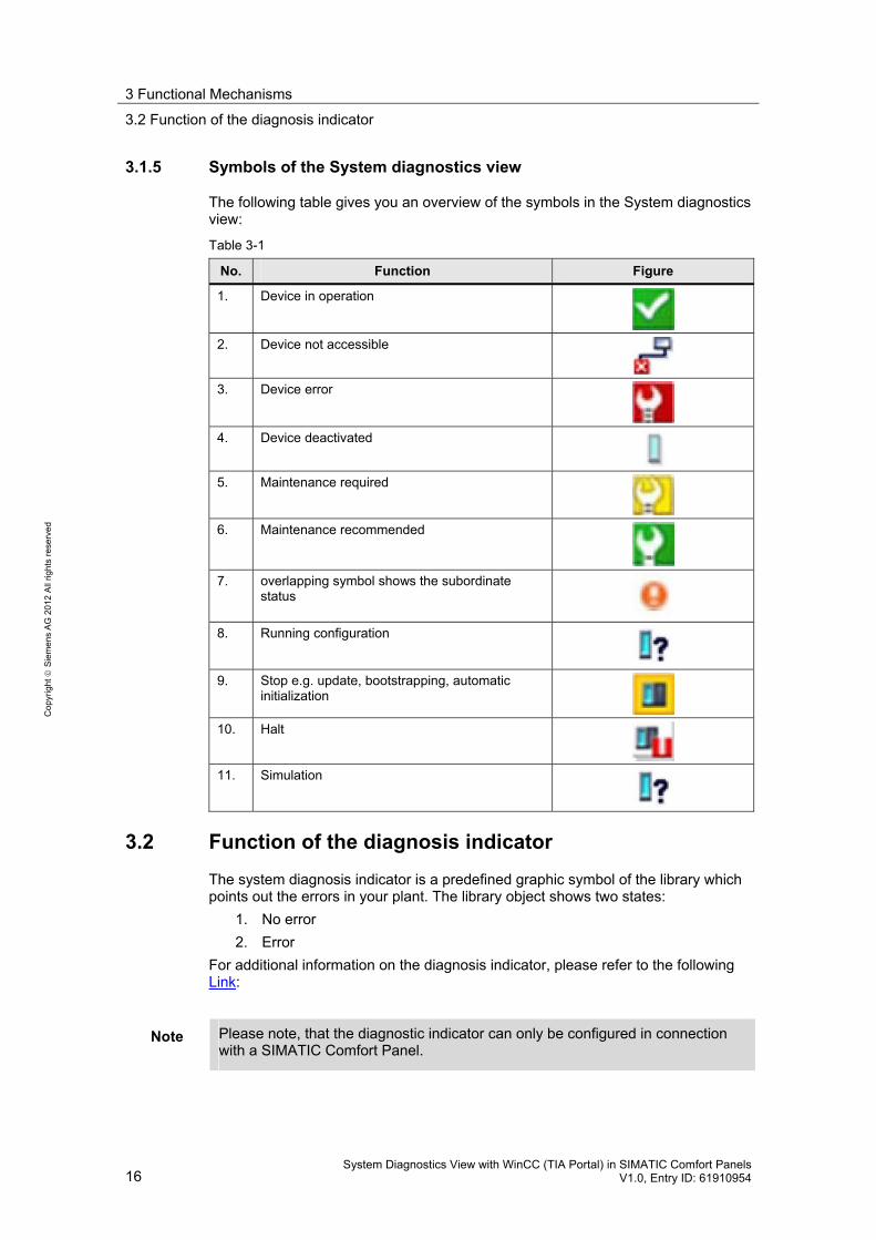
3.1.5 Symbols of the System diagnostics view
The following table gives you an overview of the symbols in the System diagnostics view:
Table 3-1
No. Function Figure
1. Device in operation
2. Device not accessible
3. Device error
4. Device deactivated
5. Maintenance required
6. Maintenance recommended
7. overlapping symbol shows the subordinate status
8. Running configuration
9. Stop e.g. update, bootstrapping, automatic initialization
10. Halt
11. Simulation
3.2 Function of the diagnosis indicator
The system diagnosis indicator is a predefined graphic symbol of the library which points out the errors in your plant. The library object shows two states:
1. No error
2. Error
For additional information on the diagnosis indicator, please refer to the following Link:
Note Please note, that the diagnostic indicator can only be configured in connection with a SIMATIC Comfort Panel.
3 Functional Mechanisms
3.3 Background on diagnostic capability
System Diagnostics View with WinCC (TIA Portal) in SIMATIC Comfort Panels V1.0, Entry ID: 61910954 17
Co
pyr
igh
t
Sie
me
ns
AG
20
12
All
righ
ts r
ese
rve
d
3.3 Background on diagnostic capability
For SIMATIC S7 controllers, there are currently two option packages, “S7-PDIAG” and “ProAgent”, for evaluating and visualizing diagnostic messages.
These two option packages or successors are not available in the TIA Portal.
The subsequent description of both option packages, “S7-PDIAG” and “ProAgent”, explains how for SIMATIC S7 controllers diagnostic messages have been evaluated and visualized so far.
3.3.1 Information on Pdiag
The S7-PDIAG option package expands the function scope of STEP 7 basic software by the option of process diagnostics for the programming languages LAD/FBD/STL. The process diagnosis detects errors in the user process (production, distribution, manufacturing processes, etc.) and determines information on:
• the error type
• the error location and
• the error cause within the your process.
Furthermore, S7-PDIAG provides you with notes for error removal at the display device (HMI).
The task of the process diagnosis is to monitor the production facilities. The basic principle of monitoring is quite simple. A comparison is made between setpoint and actual state of the process signals. This can be, for example, performed in the form of a time monitoring (e.g. permitted runtime of a slider) or also in the form of a plausibility check (e.g. the two end position signals of a valve must never operate signal "1" at the same time). Such inspections can be used to check the entire chain from command memory over the output channel, terminals, cables, actuator, end switches and input channel.
Continuing information on S7-PDIAG is available in manual “Configuring S7-PDIAG for S7-300/400 process diagnostic”, which can be downloaded under the following Link.
3.3.2 Information on ProAgent
Using SIMATIC S7 controllers enables you to configure a capable process diagnosis. It helps you to quickly detect and repair potential failures. This way, you increase the availability of your plant, shorten downtimes and reduce costs.
ProAgent is a universal system solution and designed for an optimal interaction between STEP 7, STEP 7 option packages and the WinCC flexible configuration software for operator panels. The configuration of the process diagnosis can be handled simply and quickly. This is irrespective of whether the process diagnosis must be integrated into a newly generated or an already existing project.
Continuing information on ProAgent is available in manual “SIMATIC HMI WinCC flexible 2008 ProAgent”, which can be downloaded under the following Link .
3 Functional Mechanisms
3.4 Data exchange
18 System Diagnostics View with WinCC (TIA Portal) in SIMATIC Comfort Panels
V1.0, Entry ID: 61910954
Co
pyr
igh
t
Sie
me
ns
AG
20
12
All
righ
ts r
ese
rve
d
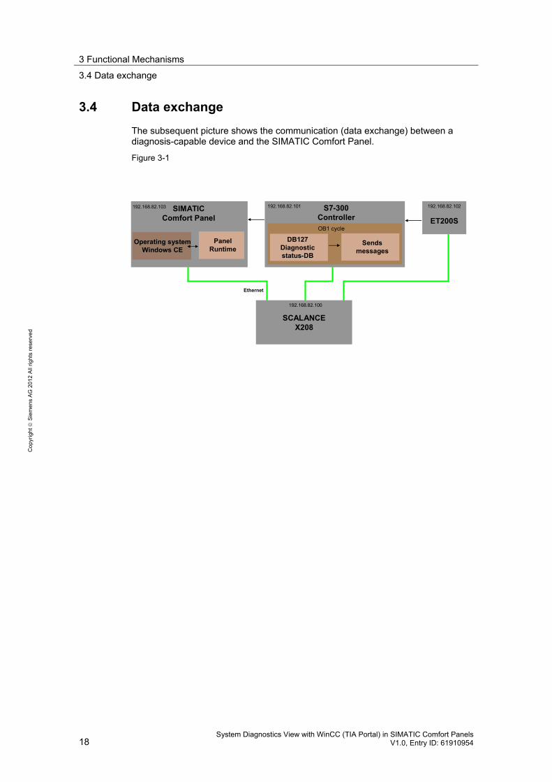
3.4 Data exchange
The subsequent picture shows the communication (data exchange) between a diagnosis-capable device and the SIMATIC Comfort Panel.
Figure 3-1
SCALANCEX208
Ethernet
SIMATICComfort Panel
Operating systemWindows CE
PanelRuntime
ET200S
192.168.82.103 192.168.82.101 192.168.82.102
192.168.82.100
S7-300ControllerOB1 cycle
DB127Diagnosticstatus-DB
Sendsmessages
4 Configuration and Settings in TIA Portal
4.1 Preparatory measures for the configuration
System Diagnostics View with WinCC (TIA Portal) in SIMATIC Comfort Panels V1.0, Entry ID: 61910954 19
Co
pyr
igh
t
Sie
me
ns
AG
20
12
All
righ
ts r
ese
rve
d
4 Configuration and Settings in TIA Portal
4.1 Preparatory measures for the configuration
Before you start with the configuration, determine the addresses of the individual hardware components.
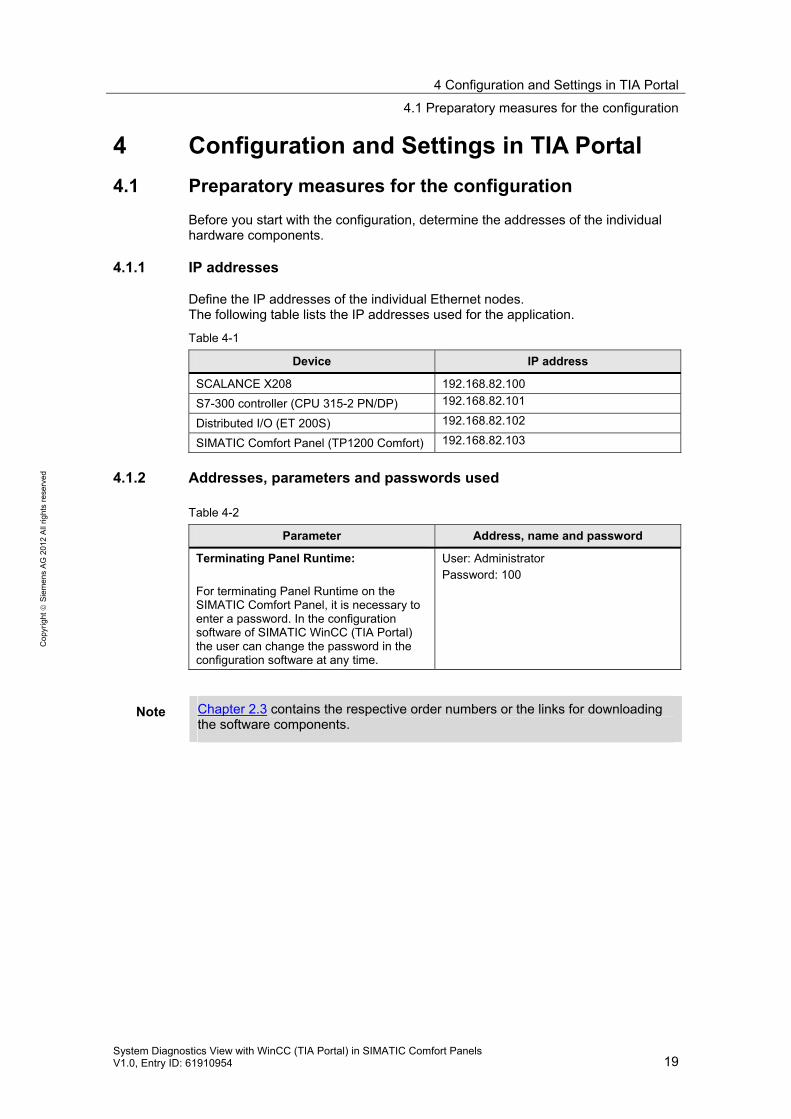
4.1.1 IP addresses
Define the IP addresses of the individual Ethernet nodes. The following table lists the IP addresses used for the application.
Table 4-1
Device IP address
SCALANCE X208 192.168.82.100
S7-300 controller (CPU 315-2 PN/DP) 192.168.82.101
Distributed I/O (ET 200S) 192.168.82.102
SIMATIC Comfort Panel (TP1200 Comfort) 192.168.82.103
4.1.2 Addresses, parameters and passwords used
Table 4-2
Parameter Address, name and password
Terminating Panel Runtime: For terminating Panel Runtime on the SIMATIC Comfort Panel, it is necessary to enter a password. In the configuration software of SIMATIC WinCC (TIA Portal) the user can change the password in the configuration software at any time.
User: Administrator Password: 100
Note Chapter 2.3 contains the respective order numbers or the links for downloading the software components.

4 Configuration and Settings in TIA Portal
4.2 Configuration of CPU 315-2 PN/DP
20 System Diagnostics View with WinCC (TIA Portal) in SIMATIC Comfort Panels
V1.0, Entry ID: 61910954
Co
pyr
igh
t
Sie
me
ns
AG
20
12
All
righ
ts r
ese
rve
d
4.2 Configuration of CPU 315-2 PN/DP
Proceed as described below to configure CPU 315-2 PN/DP and to activate the system diagnosis.
Table 4-3
No. Action Screens
1. Creating a project: Create a new project in the TIA Portal.
2. Creating an S7-300 controller: Click the “Add new device” button in the project tree.
3. Creating an S7-300 controller: A selection box opens from which you can select the CPU to be used. In this example: “6ES7 315-2EH14-0AB0” Notice: Please ensure configuring the correct CPU version.
4 Configuration and Settings in TIA Portal
4.2 Configuration of CPU 315-2 PN/DP
System Diagnostics View with WinCC (TIA Portal) in SIMATIC Comfort Panels V1.0, Entry ID: 61910954 21
Co
pyr
igh
t
Sie
me
ns
AG
20
12
All
righ
ts r
ese
rve
d
No. Action Screens
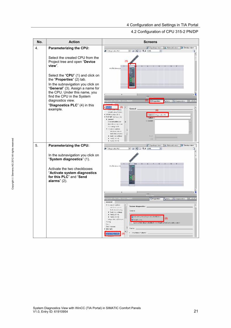
4. Parameterizing the CPU: Select the created CPU from the Project tree and open “Device view”. Select the “CPU” (1) and click on the “Properties” (2) tab. In the subnavigation you click on “General” (3). Assign a name for the CPU. Under this name, you find the CPU in the System diagnostics view. “Diagnostics PLC” (4) in this example.
5. Parameterizing the CPU: In the subnavigation you click on “System diagnostics” (1). Activate the two checkboxes “Activate system diagnostics for this PLC” and “Send alarms” (2).
(1)
(2)
(3) (4)
(1)
(2)
4 Configuration and Settings in TIA Portal
4.2 Configuration of CPU 315-2 PN/DP
22 System Diagnostics View with WinCC (TIA Portal) in SIMATIC Comfort Panels
V1.0, Entry ID: 61910954
Co
pyr
igh
t
Sie
me
ns
AG
20
12
All
righ
ts r
ese
rve
d
No. Action Screens
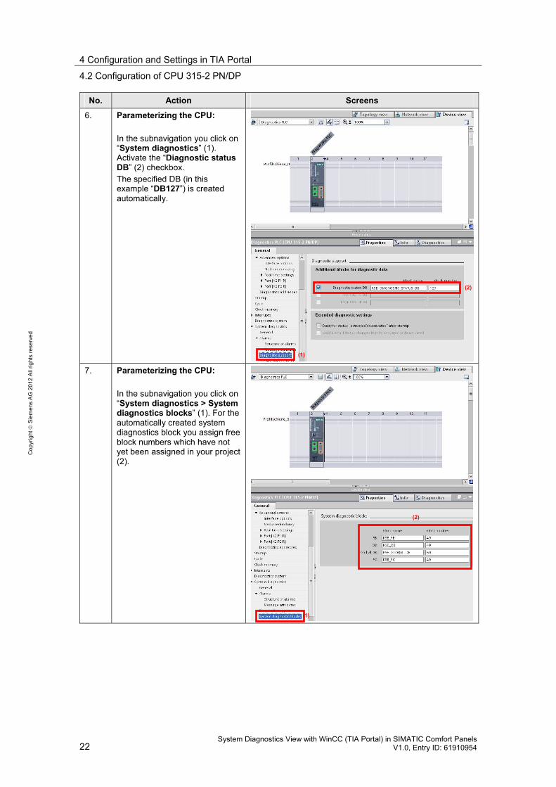
6. Parameterizing the CPU: In the subnavigation you click on “System diagnostics” (1). Activate the “Diagnostic status DB” (2) checkbox. The specified DB (in this example “DB127”) is created automatically.
7. Parameterizing the CPU: In the subnavigation you click on “System diagnostics > System diagnostics blocks” (1). For the automatically created system diagnostics block you assign free block numbers which have not yet been assigned in your project (2).
(1)
(2)
(1)
(2)
4 Configuration and Settings in TIA Portal
4.2 Configuration of CPU 315-2 PN/DP
System Diagnostics View with WinCC (TIA Portal) in SIMATIC Comfort Panels V1.0, Entry ID: 61910954 23
Co
pyr
igh
t
Sie
me
ns
AG
20
12
All
righ
ts r
ese
rve
d
No. Action Screens
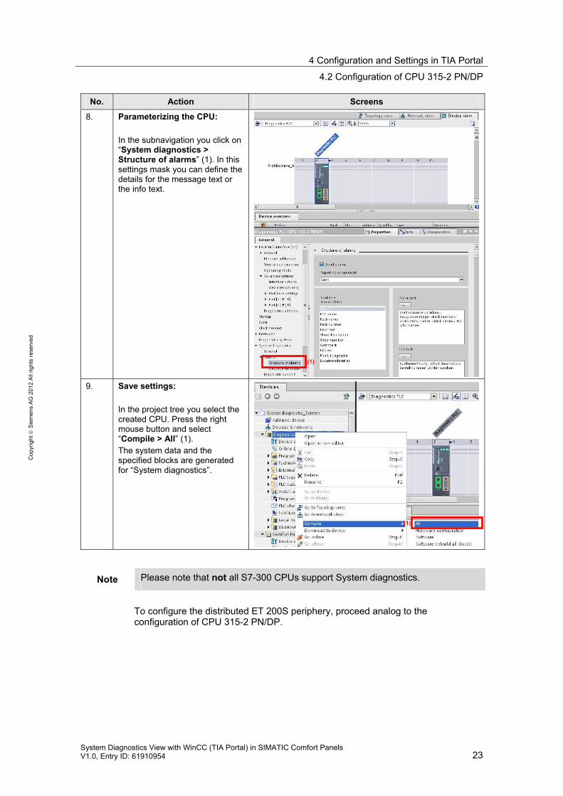
8. Parameterizing the CPU: In the subnavigation you click on “System diagnostics > Structure of alarms” (1). In this settings mask you can define the details for the message text or the info text.
9. Save settings: In the project tree you select the created CPU. Press the right mouse button and select “Compile > All” (1). The system data and the specified blocks are generated for “System diagnostics”.
Note Please note that not all S7-300 CPUs support System diagnostics.
To configure the distributed ET 200S periphery, proceed analog to the configuration of CPU 315-2 PN/DP.
(1)
(1)
4 Configuration and Settings in TIA Portal
4.3 Configuration of the SIMATIC Comfort Panel
24 System Diagnostics View with WinCC (TIA Portal) in SIMATIC Comfort Panels
V1.0, Entry ID: 61910954
Co
pyr
igh
t
Sie
me
ns
AG
20
12
All
righ
ts r
ese
rve
d
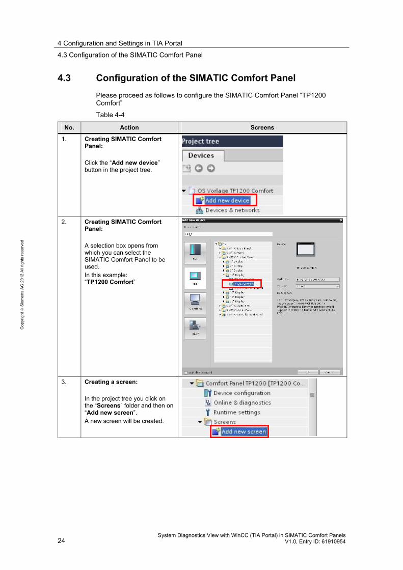
4.3 Configuration of the SIMATIC Comfort Panel
Please proceed as follows to configure the SIMATIC Comfort Panel “TP1200 Comfort”
Table 4-4
No. Action Screens
1. Creating SIMATIC Comfort Panel: Click the “Add new device” button in the project tree.
2. Creating SIMATIC Comfort Panel: A selection box opens from which you can select the SIMATIC Comfort Panel to be used. In this example: “TP1200 Comfort”
3. Creating a screen: In the project tree you click on the “Screens” folder and then on “Add new screen”. A new screen will be created.
4 Configuration and Settings in TIA Portal
4.3 Configuration of the SIMATIC Comfort Panel
System Diagnostics View with WinCC (TIA Portal) in SIMATIC Comfort Panels V1.0, Entry ID: 61910954 25
Co
pyr
igh
t
Sie
me
ns
AG
20
12
All
righ
ts r
ese
rve
d
No. Action Screens
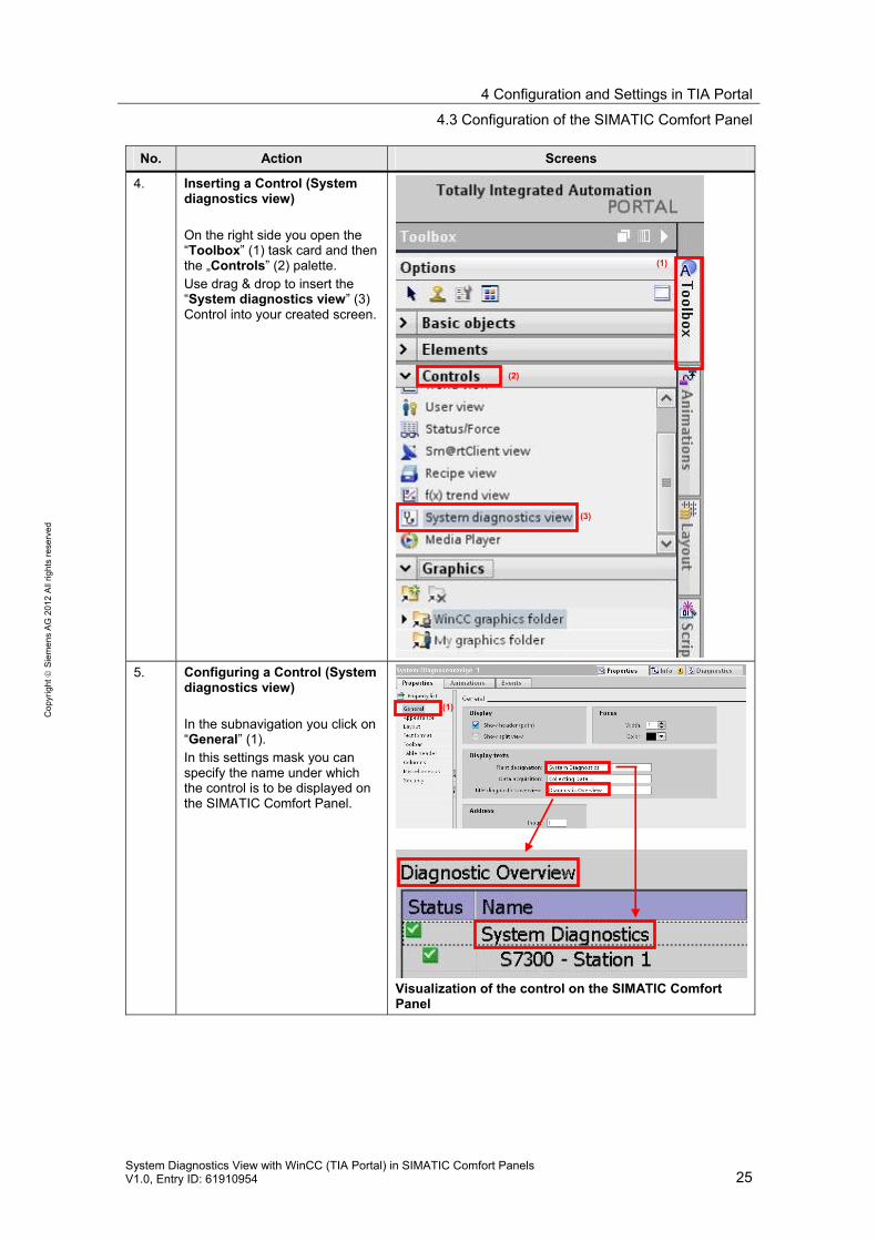
4. Inserting a Control (System diagnostics view) On the right side you open the “Toolbox” (1) task card and then the „Controls” (2) palette. Use drag & drop to insert the “System diagnostics view” (3) Control into your created screen.
5. Configuring a Control (System diagnostics view) In the subnavigation you click on “General” (1). In this settings mask you can specify the name under which the control is to be displayed on the SIMATIC Comfort Panel.
Visualization of the control on the SIMATIC Comfort Panel
(1)
(2)
(3)
(1)
4 Configuration and Settings in TIA Portal
4.3 Configuration of the SIMATIC Comfort Panel
26 System Diagnostics View with WinCC (TIA Portal) in SIMATIC Comfort Panels
V1.0, Entry ID: 61910954
Co
pyr
igh
t
Sie
me
ns
AG
20
12
All
righ
ts r
ese
rve
d
No. Action Screens
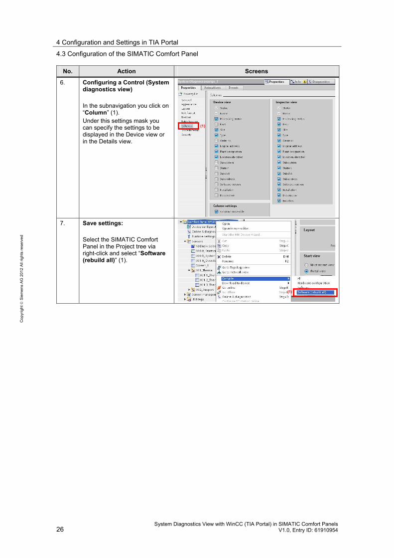
6. Configuring a Control (System diagnostics view) In the subnavigation you click on “Column” (1). Under this settings mask you can specify the settings to be displayed in the Device view or in the Details view.
7. Save settings: Select the SIMATIC Comfort Panel in the Project tree via right-click and select “Software (rebuild all)” (1).
(1)
(1)
4 Configuration and Settings in TIA Portal
4.3 Configuration of the SIMATIC Comfort Panel
System Diagnostics View with WinCC (TIA Portal) in SIMATIC Comfort Panels V1.0, Entry ID: 61910954 27
Co
pyr
igh
t
Sie
me
ns
AG
20
12
All
righ
ts r
ese
rve
d
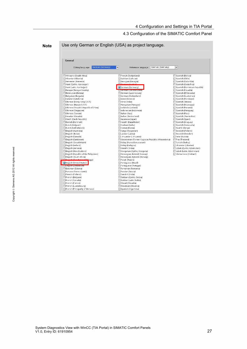
Note Use only German or English (USA) as project language.
5 Starting up the Application
5.1 Preparing measures
28 System Diagnostics View with WinCC (TIA Portal) in SIMATIC Comfort Panels
V1.0, Entry ID: 61910954
Co
pyr
igh
t
Sie
me
ns
AG
20
12
All
righ
ts r
ese
rve
d
5 Starting up the Application
5.1 Preparing measures
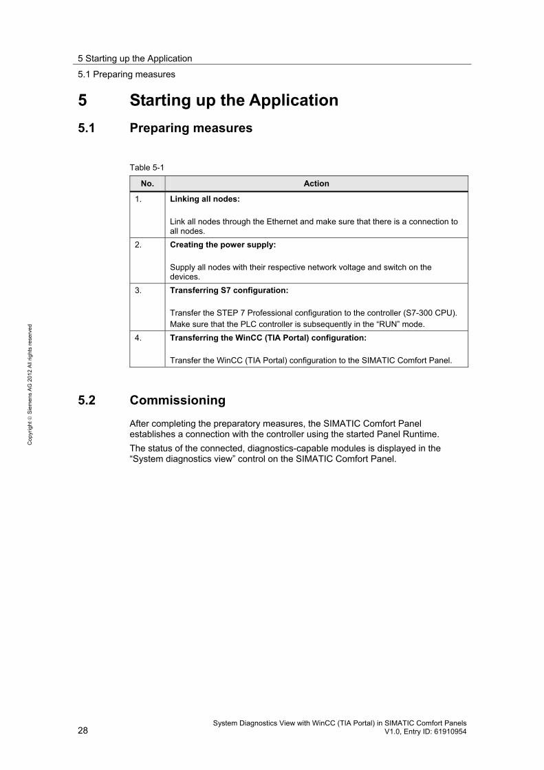
Table 5-1
No. Action
1. Linking all nodes: Link all nodes through the Ethernet and make sure that there is a connection to all nodes.
2. Creating the power supply: Supply all nodes with their respective network voltage and switch on the devices.
3. Transferring S7 configuration: Transfer the STEP 7 Professional configuration to the controller (S7-300 CPU). Make sure that the PLC controller is subsequently in the “RUN” mode.
4. Transferring the WinCC (TIA Portal) configuration: Transfer the WinCC (TIA Portal) configuration to the SIMATIC Comfort Panel.
5.2 Commissioning
After completing the preparatory measures, the SIMATIC Comfort Panel establishes a connection with the controller using the started Panel Runtime.
The status of the connected, diagnostics-capable modules is displayed in the “System diagnostics view” control on the SIMATIC Comfort Panel.
6 Operation of the Application
5.2 Commissioning
System Diagnostics View with WinCC (TIA Portal) in SIMATIC Comfort Panels V1.0, Entry ID: 61910954 29
Co
pyr
igh
t
Sie
me
ns
AG
20
12
All
righ
ts r
ese
rve
d
6 Operation of the Application
WinCC (TIA Portal) configuration
A SIMATIC Comfort Panel with WinCC (TIA Portal) was configured for this application. The project consists of the following screens.
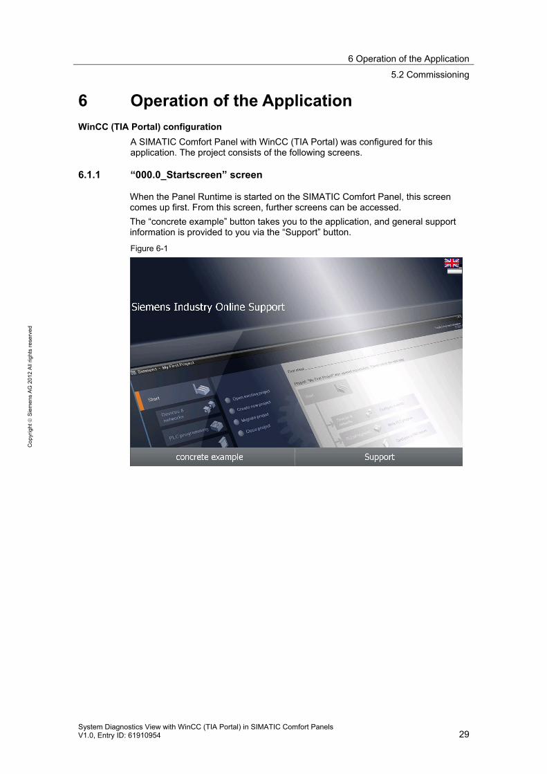
6.1.1 “000.0_Startscreen” screen
When the Panel Runtime is started on the SIMATIC Comfort Panel, this screen comes up first. From this screen, further screens can be accessed.
The “concrete example” button takes you to the application, and general support information is provided to you via the “Support” button.
Figure 6-1
6 Operation of the Application
5.2 Commissioning
30 System Diagnostics View with WinCC (TIA Portal) in SIMATIC Comfort Panels
V1.0, Entry ID: 61910954
Co
pyr
igh
t
Sie
me
ns
AG
20
12
All
righ
ts r
ese
rve
d
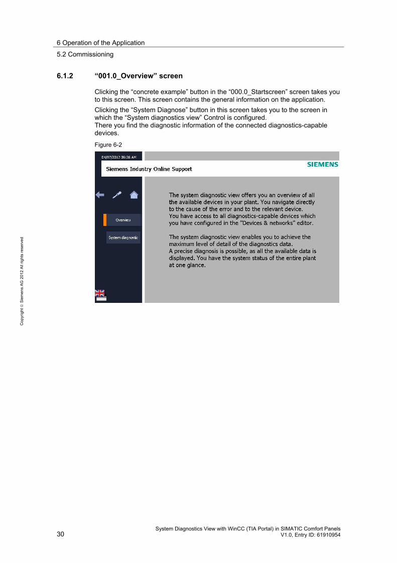
6.1.2 “001.0_Overview” screen
Clicking the “concrete example” button in the “000.0_Startscreen” screen takes you to this screen. This screen contains the general information on the application.
Clicking the “System Diagnose” button in this screen takes you to the screen in which the “System diagnostics view” Control is configured. There you find the diagnostic information of the connected diagnostics-capable devices.
Figure 6-2
6 Operation of the Application
5.2 Commissioning
System Diagnostics View with WinCC (TIA Portal) in SIMATIC Comfort Panels V1.0, Entry ID: 61910954 31
Co
pyr
igh
t
Sie
me
ns
AG
20
12
All
righ
ts r
ese
rve
d
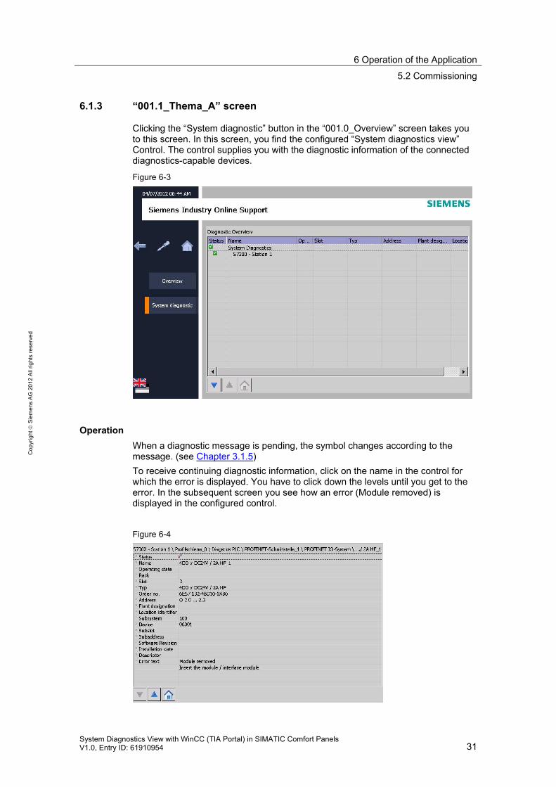
6.1.3 “001.1_Thema_A” screen
Clicking the “System diagnostic” button in the “001.0_Overview” screen takes you to this screen. In this screen, you find the configured “System diagnostics view” Control. The control supplies you with the diagnostic information of the connected diagnostics-capable devices.
Figure 6-3
Operation
When a diagnostic message is pending, the symbol changes according to the message. (see Chapter 3.1.5)
To receive continuing diagnostic information, click on the name in the control for which the error is displayed. You have to click down the levels until you get to the error. In the subsequent screen you see how an error (Module removed) is displayed in the configured control.
Figure 6-4
6 Operation of the Application
5.2 Commissioning
32 System Diagnostics View with WinCC (TIA Portal) in SIMATIC Comfort Panels
V1.0, Entry ID: 61910954
Co
pyr
igh
t
Sie
me
ns
AG
20
12
All
righ
ts r
ese
rve
d
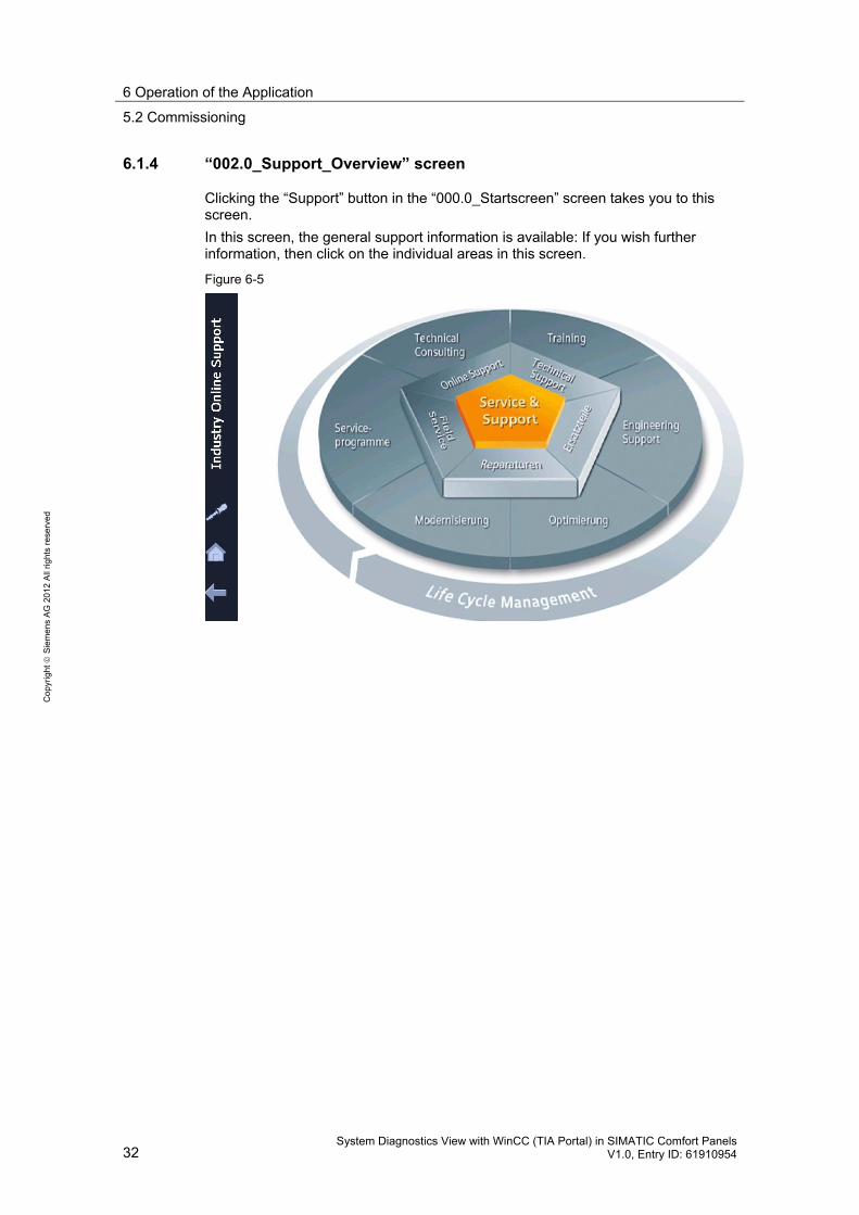
6.1.4 “002.0_Support_Overview” screen
Clicking the “Support” button in the “000.0_Startscreen” screen takes you to this screen.
In this screen, the general support information is available: If you wish further information, then click on the individual areas in this screen.
Figure 6-5
6 Operation of the Application
5.2 Commissioning
System Diagnostics View with WinCC (TIA Portal) in SIMATIC Comfort Panels V1.0, Entry ID: 61910954 33
Co
pyr
igh
t
Sie
me
ns
AG
20
12
All
righ
ts r
ese
rve
d
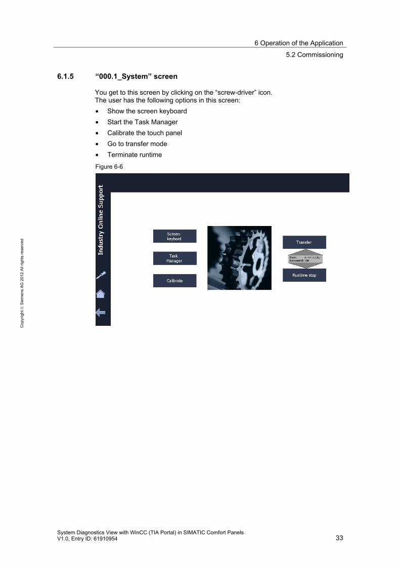
6.1.5 “000.1_System” screen
You get to this screen by clicking on the “screw-driver” icon. The user has the following options in this screen:
• Show the screen keyboard
• Start the Task Manager
• Calibrate the touch panel
• Go to transfer mode
• Terminate runtime
Figure 6-6
7 Links & Literature
34 System Diagnostics View with WinCC (TIA Portal) in SIMATIC Comfort Panels
V1.0, Entry ID: 61910954
Co
pyr
igh
t
Sie
me
ns
AG
20
12
All
righ
ts r
ese
rve
d
7 Links & Literature
7.1 Literature
The following list is by no means complete and only provides a selection of appropriate information.
Table 7-1
No. Topic Title
1. STEP7 SIMATIC S7-300
Automating with SIMATIC S7-300 inside TIA Portal Author: Hans Berger Publicis MCD Verlag ISBN: 978-3-89578-357-9
2. STEP7 SIMATIC S7-400
Automating with SIMATIC S7-400 inside TIA Portal Author: Hans Berger Publicis MCD Verlag ISBN: 978-3-89578-372-2
3. STEP7 SIMATIC S7-1200
Automating with SIMATIC S7-1200 Author: Hans Berger Publicis MCD Verlag ISBN: 978-3-89578-355-5
7.2 Internet links
The following list is by no means complete and only provides a selection of appropriate sources.
Table 7-2
Topic Title
1. Link to this document http://support.automation.siemens.com/WW/view/en/61910954
2. Siemens Industry Online Support
http://support.automation.siemens.com
3. “WinCC Advanced V11 SP2” Manual
http://support.automation.siemens.com/WW/view/en/57358923
4. “STEP 7 Professional V11.0 SP2” Manual
http://support.automation.siemens.com/WW/view/en/57185407
5. SIMATIC WinCC (TIA Portal) SP2
http://support.automation.siemens.com/WW/view/en/56897511
6. SIMATIC WinCC (TIA Portal) SP2 Update 3
http://support.automation.siemens.com/WW/view/en/59604410
7. STEP 7 Professional V11 SP2 Update 3
http://support.automation.siemens.com/WW/view/en/59604410
8. System diagnostics indicator
https://www.automation.siemens.com/mdm/default.aspx?DocVersionId=37364590091&Language=de-DE&TopicId=21593680011
9. S7-PDIAG Manual http://support.automation.siemens.com/WW/view/en/16531809
10. ProAgent Manual http://support.automation.siemens.com/WW/view/en/34594937
8 History
System Diagnostics View with WinCC (TIA Portal) in SIMATIC Comfort Panels V1.0, Entry ID: 61910954 35
Co
pyr
igh
t
Sie
me
ns
AG
20
12
All
righ
ts r
ese
rve
d
8 History
Table 8-1
Version Date Revisions
V1.0 08/2012 First issue