ti designs bluetooth smart to wi-fi iot · pdf filecc3200 cc26xx uart cc26xx reset t general...
TRANSCRIPT

CC3200 CC26XX
UART
CC26XX Reset
UA
RT
General Purpose IO
JT
AG
JT
AG
Re
set
GP
IOs(4
)
SO
P
SPISerialFlash
2 Buttons2 LEDs
SOPButton
RSTButton
1TIDUA62B–July 2015–Revised January 2016Submit Documentation Feedback
Copyright © 2015–2016, Texas Instruments Incorporated
Bluetooth® Smart to Wi-Fi® IoT Gateway
TI DesignsBluetooth® Smart to Wi-Fi® IoT Gateway
SimpleLink, Code Composer Studio, Internet-on-a-Chip are trademarks of Texas Instruments.ARM is a registered trademark of ARM Limited .Cortex is a registered trademark of ARM Limited.Bluetooth is a registered trademark of Bluetooth SIG.Chrome is a registered trademark of Google Inc.IBM is a registered trademark of IBM Corporatoin.HyperTerminal is a registered trademark of Microsoft Corporation.Internet Explorer is a trademark of Microsoft Inc.Firefox is a registered trademark of Mozilla Inc.Silabs is a trademark of Silicon Laboratories.Wi-Fi, Wi-Fi certified are registered trademarks of Wi-Fi Alliance.ZigBee is a trademark of ZigBee Alliance.All other trademarks are the property of their respective owners.
TI DesignsTI Designs provide the foundation that you needincluding methodology, testing and design files toquickly evaluate and customize the system. TI Designshelp you accelerate your time to market.
Design Resources
TIDC-BLE-TO-WIFI-IOT-GATEWAY TI Design FilesCC2650 Product FolderCC3200 Product FolderTPS79601 Product FolderTPD2EUSB30 Product Folder
ASK Our E2E ExpertsWEBENCH® Calculator Tools
Design Features• Connect Bluetooth Smart Devices To IoT Cloud• USB Powered, Small Form Factor, Low-Power Wi-
Fi® Connection• USB (Over UART) Command Interface For
Configuration—Works With SensorTag• HTTP Server and Pages For Configuration• Single-Board Bluetooth® Smart Wi-Fi Integrated
Design• MQTT Protocol Enabled For IoT Connectivity• Over-The-Air (OTA) Firmware Update
Featured Applications• Internet of Things (IoT)• Social Alerts• Health and Fitness• Remote Tracking
An IMPORTANT NOTICE at the end of this TI reference design addresses authorized use, intellectual property matters and otherimportant disclaimers and information.

Key System Specifications www.ti.com
2 TIDUA62B–July 2015–Revised January 2016Submit Documentation Feedback
Copyright © 2015–2016, Texas Instruments Incorporated
Bluetooth® Smart to Wi-Fi® IoT Gateway
1 Key System Specifications
Table 1. Key System Specifications
PARAMETER SPECIFICATION DETAILS
Wi-Fi chipA Single-Chip Wireless MCU with
integrated Wi-Fi network processor andpower management subsystem
Refer to the following link:http://www.ti.com/product/cc3200
Bluetooth Smart chip
The CC2650 is a wireless MCU targetingBluetooth Smart, ZigBee™ and
6LoWPAN, and ZigBee RF4CE remotecontrol applications
Refer to the following link:http://www.ti.com/product/cc2650
Power chip
The TPS79601 low dropout (LDO) low-power linear voltage regulator features
ultralow-noise and excellent line and loadtransient responses in small outline, 3 × 3
VSON package
Refer to the following link:http://www.ti.com/product/tps79601/descri
ption
ESD chip
The TPD2EUSB30 are 2 channelTransient Voltage Suppressor (TVS)based Electrostatic Discharge (ESD)
protection diode arrays
Refer to the following link:http://www.ti.com/product/TPD2EUSB30
Antenna2450AT18D0100 for Bluetooth Smart and
2450AT42B100 for Wi-Fi. 2.4 Ghz,ceramic chip antenna
Refer to the following links:http://www.johansontechnology.com/datas
heets/antennas/2450AT18D0100.pdfhttp://www.johansontechnology.com/datas
heets/antennas/2450AT42B100.pdfVIN Input voltage 5 V, USB powered
VOUT Output voltage 3.3 V, powers the gateway
1.1 DeliverablesThe Bluetooth Smart to Wi-Fi Gateway TI design comprises the following mentioned collaterals.
1.1.1 Hardware Design FilesThe hardware design files help the customer design a custom board. The package includes schematics,layout, and Gerber files.
1.1.2 Software SourceThe software package contains all the gateway source files. The software is modular, which makes iteasier for the developer to include a particular module.
1.1.3 CollateralsThis design guide explains the usage of the gateway.

CC3200 CC26XX
UART
CC26XX Reset
UA
RT
General Purpose IO
JT
AG
JT
AG
Re
set
GP
IOs(4
)
SO
P
SPISerialFlash
2 Buttons2 LEDs
SOPButton
RSTButton
www.ti.com System Description
3TIDUA62B–July 2015–Revised January 2016Submit Documentation Feedback
Copyright © 2015–2016, Texas Instruments Incorporated
Bluetooth® Smart to Wi-Fi® IoT Gateway
2 System Description
Figure 1. The Gateway Block Diagram
This Bluetooth Smart-to-Wi-Fi Gateway solution connects the Bluetooth Smart devices to the cloud overWi-Fi. The integrated hardware solution comprises the CC3200 Wi-Fi wireless MCU and the CC2650Wireless MCU on a single board. Customers may reuse the reference design to design their own gateway.The software and hardware design resources reduce engineering efforts, shorten time to market, and helpdevelopers and customers release their products with cloud connectivity features faster.
The CC3200 Wireless MCU is an intelligent, low-power Wi-Fi chip with an ARM® Cortex®-M4 applicationprocessor. The CC3200 contains a wireless network processor with stable and certified TCP / IP stackintegrated on a single chip. The device comes with on-chip security protocols and various networkapplication protocols (HTTP, mDNS, and others). CC3200 is the first and only chip in the world to be Wi-Ficertified® by the Wi-Fi alliance at chip level.
The CC3200 SDK (Software Development Kit) facilitates easy development experience for the user. TheCC3200 contains CCS, IAR and GCC toolchain support, app notes and extensive user guides. TheSimpleLink™ APIs provide an easy and well abstracted access to the stack functionality. The SDKprovides MQTT support (for IoT), OTA (Over The Air) download support, and numerous MCU examples,which reduces the development effort and thereby reduces the time to market. Extensive E2E supportfrom TI helps the developers at every stage.
CC2650 is an ultralow-power wireless MCU capable of running multiple protocols (Bluetooth Smart,ZigBee, and 6LowPAN). This wireless MCU can run for years even when powered by coin-cell batteries orany energy-harvested sources.
The CC2650 platform comes ready-to-use, royalty free, and with certified wireless protocol stacks, TIRTOS, Code Composer Studio™ integrated development environment (IDE), development tools, onlinetraining, and E2E community support.
The CC3200 Wireless MCU powers the entire board and also communicates and controls the CC2650Bluetooth Smart Wireless MCU over UART. With the support of its built-in Wi-Fi network processor, theCC3200 Wireless MCU ensures seamless connection with the remote cloud. The CC2650 Wireless MCUcan connect to multiple Bluetooth Smart devices.
Two LED indicators are provided to indicate the status. Two buttons are provided to trigger variousactions. A simple button is provided to switch the CC3200 to UARTLoad mode. Debugging andprogramming options for both CC3200 and CC2650 chips are provided by dedicated JTAG ports.
The gateway can easily be configured for the first time using the Command Line Interface (CLI). UniFlashflashes the binaries on CC3200.
A 1-MB Serial Flash (SFLASH) is provided for storing the binaries, configuration files, and http pages.
A dedicated RESET button is provided to bring the gateway out of unknown conditions duringdevelopment.

Main CPU
Sensor controller
ARM®
Cortex®
Sensor controller
engine
2× Analog comparators
12-bit ADC, 200 ks/s
Constant current source
SPI / I C digital sensor IF2
2 KB SRAM
SimpleLink™ ULP wireless MCU platform
Up to
128 KB
Flash
cJTAG
20 KB
SRAM
8 KB
cache
ROM
DC / DC converter
General peripherals / modules
4× 32-bit timers
2× SSI (SPI, µW, TI)
Watchdog timer
TRNG
Temp. / batt. monitor
RTC
I C2
UART
I2S
10 / 15 / 31 GPIOs
AES
32 ch. µDMA
RF core2.4 GHz
Sub-1GHz
DSP modem
ADC
ADC
Digital PLL
4 KB
SRAM
ROM
Radio
controller
Time-to-digital converter
-M3
System Description www.ti.com
4 TIDUA62B–July 2015–Revised January 2016Submit Documentation Feedback
Copyright © 2015–2016, Texas Instruments Incorporated
Bluetooth® Smart to Wi-Fi® IoT Gateway
2.1 CC2650—Wireless MCU
Figure 2. CC2650 Block Diagram
The CC2650 is a wireless-MCU-targeting Bluetooth Smart application. The device is a member of theCC26xx family of cost-effective, ultralow-power, 2.4-GHz RF devices. Very low active RF currentconsumption and very low MCU current consumption provide excellent battery lifetime and allowsoperation on small-coin cell batteries and in energy-harvesting applications. The CC2650 contains a 32-bitARM Cortex M3 running at 48-MHz as the main processor and a rich peripheral feature set. This setincludes a unique ultralow-power sensor controller, which is ideal for interfacing external sensors andcollecting analog and digital data autonomously while the rest of the system is in sleep mode.
CC2650 is a Network Processor in the gateway design. For more details of CC2650, see the productpage.
2.2 CC3200—Wireless MCUThe CC3200 MCU subsystem contains an industry-standard ARM Cortex M4 core running at 80 MHz. Thedevice includes a wide variety of peripherals, including a fast parallel camera interface, I2S, SD / MMC,UART, SPI, I2C, and four-channel ADC. The CC3200 family includes flexible embedded RAM for code anddata, and ROM with an external serial flash bootloader and peripheral drivers.
www.ti.com System Description
5TIDUA62B–July 2015–Revised January 2016Submit Documentation Feedback
Copyright © 2015–2016, Texas Instruments Incorporated
Bluetooth® Smart to Wi-Fi® IoT Gateway
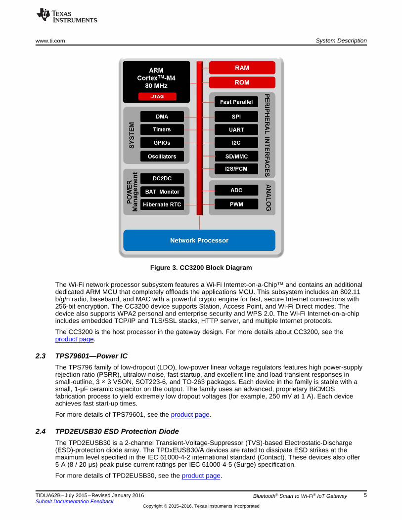
Figure 3. CC3200 Block Diagram
The Wi-Fi network processor subsystem features a Wi-Fi Internet-on-a-Chip™ and contains an additionaldedicated ARM MCU that completely offloads the applications MCU. This subsystem includes an 802.11b/g/n radio, baseband, and MAC with a powerful crypto engine for fast, secure Internet connections with256-bit encryption. The CC3200 device supports Station, Access Point, and Wi-Fi Direct modes. Thedevice also supports WPA2 personal and enterprise security and WPS 2.0. The Wi-Fi Internet-on-a-chipincludes embedded TCP/IP and TLS/SSL stacks, HTTP server, and multiple Internet protocols.
The CC3200 is the host processor in the gateway design. For more details about CC3200, see theproduct page.
2.3 TPS79601—Power ICThe TPS796 family of low-dropout (LDO), low-power linear voltage regulators features high power-supplyrejection ratio (PSRR), ultralow-noise, fast startup, and excellent line and load transient responses insmall-outline, 3 × 3 VSON, SOT223-6, and TO-263 packages. Each device in the family is stable with asmall, 1-μF ceramic capacitor on the output. The family uses an advanced, proprietary BiCMOSfabrication process to yield extremely low dropout voltages (for example, 250 mV at 1 A). Each deviceachieves fast start-up times.
For more details of TPS79601, see the product page.
2.4 TPD2EUSB30 ESD Protection DiodeThe TPD2EUSB30 is a 2-channel Transient-Voltage-Suppressor (TVS)-based Electrostatic-Discharge(ESD)-protection diode array. The TPDxEUSB30/A devices are rated to dissipate ESD strikes at themaximum level specified in the IEC 61000-4-2 international standard (Contact). These devices also offer5-A (8 / 20 μs) peak pulse current ratings per IEC 61000-4-5 (Surge) specification.
For more details of TPD2EUSB30, see the product page.
Gateway
Internet WLAN
Other Bluetooth Smart Devices
Bluetooth Smart
Thermostat
Bluetooth Smart Bulbs
Bluetooth Smart Lock
Bluetooth Smart Speakers
System Design Theory www.ti.com
6 TIDUA62B–July 2015–Revised January 2016Submit Documentation Feedback
Copyright © 2015–2016, Texas Instruments Incorporated
Bluetooth® Smart to Wi-Fi® IoT Gateway
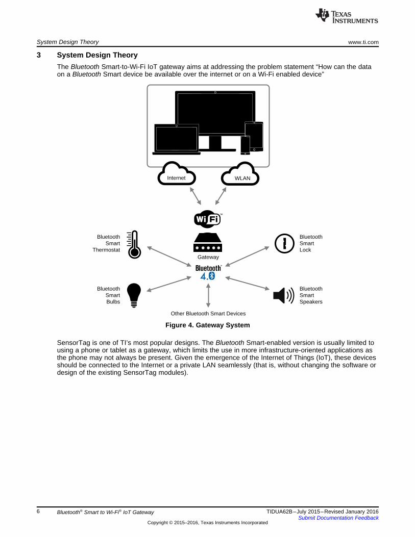
3 System Design TheoryThe Bluetooth Smart-to-Wi-Fi IoT gateway aims at addressing the problem statement “How can the dataon a Bluetooth Smart device be available over the internet or on a Wi-Fi enabled device”
Figure 4. Gateway System
SensorTag is one of TI’s most popular designs. The Bluetooth Smart-enabled version is usually limited tousing a phone or tablet as a gateway, which limits the use in more infrastructure-oriented applications asthe phone may not always be present. Given the emergence of the Internet of Things (IoT), these devicesshould be connected to the Internet or a private LAN seamlessly (that is, without changing the software ordesign of the existing SensorTag modules).
Driver
HCI
Parser
Gateway
Enabler
Bluetooth
Smart
Stack
HCI Packets
TCP / IP
Stack
MQTT HTTP CLI
CC3200 CC26XX
HCIL2NMP_COMMON
L2NMP_PSS (BLE)
www.ti.com System Design Theory
7TIDUA62B–July 2015–Revised January 2016Submit Documentation Feedback
Copyright © 2015–2016, Texas Instruments Incorporated
Bluetooth® Smart to Wi-Fi® IoT Gateway
3.1 Architecture
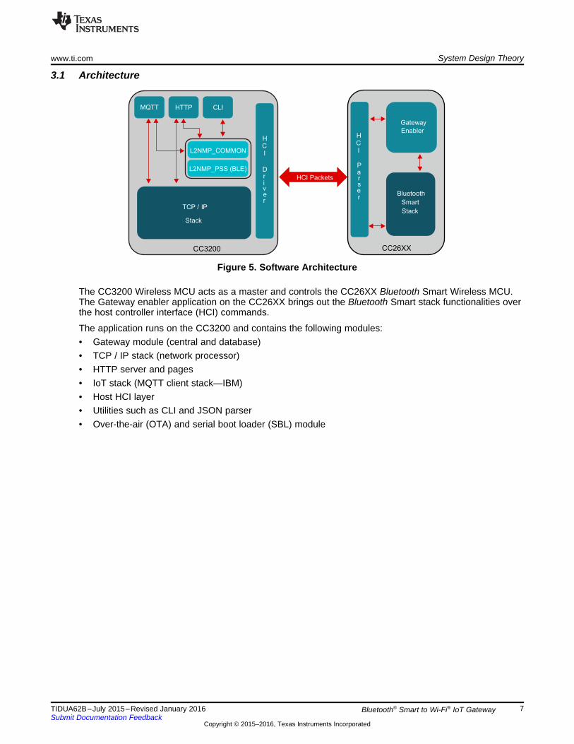
Figure 5. Software Architecture
The CC3200 Wireless MCU acts as a master and controls the CC26XX Bluetooth Smart Wireless MCU.The Gateway enabler application on the CC26XX brings out the Bluetooth Smart stack functionalities overthe host controller interface (HCI) commands.
The application runs on the CC3200 and contains the following modules:• Gateway module (central and database)• TCP / IP stack (network processor)• HTTP server and pages• IoT stack (MQTT client stack—IBM)• Host HCI layer• Utilities such as CLI and JSON parser• Over-the-air (OTA) and serial boot loader (SBL) module

Print the Banner Initialize L2NMP and HCI
Initialize Board Hardware
Start
Start Wi-Fi Stack
Connect to AP
Initialize every module
Wait for User Input on UART Initialize Bluetooth Smart Stack
Wait on GW_Q for any
input from other tasks
CLI Gateway
Connect to MQTT server
Wait for subscribed topics
Post to GW_Q if needed
MQTT
Post to GW_Q if not needed
System Design Theory www.ti.com
8 TIDUA62B–July 2015–Revised January 2016Submit Documentation Feedback
Copyright © 2015–2016, Texas Instruments Incorporated
Bluetooth® Smart to Wi-Fi® IoT Gateway
3.2 Working PrincipleThe software is a multitask architecture. The initialization sequence spawns the tasks and executesvarious module-initialization functions.
Figure 6. Initialization Sequence on CC3200 MCU
When configured, the gateway acts as a data pipe between the Bluetooth Smart devices and themonitoring entity (on Wi-Fi). No special configuration or code change is needed on the Bluetooth Smartdevice to remote it to the gateway.

DATA FLOW
IOT (over MQTT)
CLI (UART)
Devic
es
Bluetooth Smart to Wi-Fi IoT Gateway
www.ti.com Getting Started Hardware
9TIDUA62B–July 2015–Revised January 2016Submit Documentation Feedback
Copyright © 2015–2016, Texas Instruments Incorporated
Bluetooth® Smart to Wi-Fi® IoT Gateway
Figure 7. Data Flow
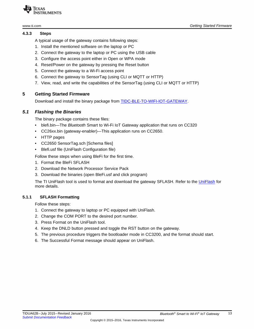
The gateway setup comprises of WLAN connection and Bluetooth Smart device connection. When thesetup is complete, you can monitor the characteristics of the device over MQTT, HTTP, or CLI. With thesoftware architecture, users can easily remove a particular entity from the binary (to reduce the size).
OTA download functionality is also present in the gateway. OTA can update the binary and also theGateway Enabler binary.
4 Getting Started HardwareThe primary feature of the gateway is to make the characteristics of a connected Bluetooth Smart deviceavailable on the cloud (IoT using MQTT). The gateway can be controlled over a local LAN using HTTPpages.
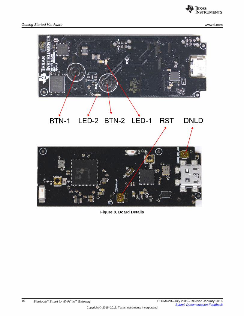
Starting the gateway hardware is an easy process. To power on the gateway, connect it to a PC or a wall-mount USB adapter through the USB cable provided in the package. Connecting the gateway to a PCprovides access to the command line interface on a terminal (TeraTerm or HyperTerminal®), which aids incontrolling or monitoring the gateway. When connected, press the RESET button to start the gateway.
LED-2 LED-1BTN-2BTN-1 RST DNLD
Getting Started Hardware www.ti.com
10 TIDUA62B–July 2015–Revised January 2016Submit Documentation Feedback
Copyright © 2015–2016, Texas Instruments Incorporated
Bluetooth® Smart to Wi-Fi® IoT Gateway
Figure 8. Board Details
Sensor Tag
USB
Gateway
Access point
www.ti.com Getting Started Hardware
11TIDUA62B–July 2015–Revised January 2016Submit Documentation Feedback
Copyright © 2015–2016, Texas Instruments Incorporated
Bluetooth® Smart to Wi-Fi® IoT Gateway
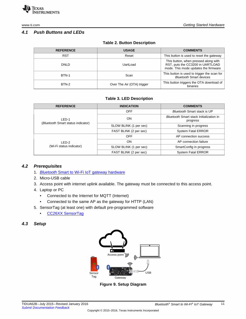
4.1 Push Buttons and LEDs
Table 2. Button Description
REFERENCE USAGE COMMENTSRST Reset This button is used to reset the gateway
DNLD UartLoadThis button, when pressed along withRST, puts the CC3200 in UARTLOADmode. This mode updates the firmware
BTN-1 Scan This button is used to trigger the scan forBluetooth Smart devices
BTN-2 Over The Air (OTA) trigger This button triggers the OTA download ofbinaries
Table 3. LED Description
REFERENCE INDICATION COMMENTS
LED-1(Bluetooth Smart status indicator)
OFF Bluetooth Smart stack is UP
ON Bluetooth Smart stack Initialization inprogress
SLOW BLINK (1 per sec) Scanning in progressFAST BLINK (2 per sec) System Fatal ERROR
LED-2(Wi-Fi status indicator)
OFF AP connection successON AP connection failure
SLOW BLINK (1 per sec) SmartConfig in progressFAST BLINK (2 per sec) System Fatal ERROR
4.2 Prerequisites1. Bluetooth Smart to Wi-Fi IoT gateway hardware2. Micro-USB cable3. Access point with internet uplink available. The gateway must be connected to this access point.4. Laptop or PC
• Connected to the Internet for MQTT (Internet)• Connected to the same AP as the gateway for HTTP (LAN)
5. SensorTag (at least one) with default pre-programmed software• CC26XX SensorTag
4.3 Setup
Figure 9. Setup Diagram

Getting Started Hardware www.ti.com
12 TIDUA62B–July 2015–Revised January 2016Submit Documentation Feedback
Copyright © 2015–2016, Texas Instruments Incorporated
Bluetooth® Smart to Wi-Fi® IoT Gateway
4.3.1 Laptop / PC Installations• Download and install UniFlash (to flash CC3200 binaries and service pack) from the link here:
http://www.ti.com/tool/uniflash• Download and install TeraTerm: http://download.cnet.com/Tera-Term/3000-20432_4-75766675.html• Download and install the latest Silabs™ virtual COM port driver for the CP2104 USB bridge IC (based
on the OS) from the link here:http://www.silabs.com/products/mcu/Pages/USBtoUARTBridgeVCPDrivers.aspx.– The gateway COM ports appear in the device manager of the PC as Silicon Labs Standard COM
CP210x USB to UART Bridge: Enhanced COM Port• Download and install the latest CC3200 SDK and service packs from the link here:
http://www.ti.com/tool/cc3200sdk
4.3.2 Access Point (AP) ConfigurationConfigure the access point in Open or WPA mode. If the AP is configured in WPA mode, write down thesecurity key.
www.ti.com Getting Started Firmware
13TIDUA62B–July 2015–Revised January 2016Submit Documentation Feedback
Copyright © 2015–2016, Texas Instruments Incorporated
Bluetooth® Smart to Wi-Fi® IoT Gateway
4.3.3 StepsA typical usage of the gateway contains following steps:1. Install the mentioned software on the laptop or PC2. Connect the gateway to the laptop or PC using the USB cable3. Configure the access point either in Open or WPA mode4. Reset/Power on the gateway by pressing the Reset button5. Connect the gateway to a Wi-Fi access point6. Connect the gateway to SensorTag (using CLI or MQTT or HTTP)7. View, read, and write the capabilities of the SensorTag (using CLI or MQTT or HTTP)
5 Getting Started FirmwareDownload and install the binary package from TIDC-BLE-TO-WIFI-IOT-GATEWAY.
5.1 Flashing the BinariesThe binary package contains these files:• blefi.bin—The Bluetooth Smart to Wi-Fi IoT Gateway application that runs on CC320• CC26xx.bin (gateway-enabler)—This application runs on CC2650.• HTTP pages• CC2650 SensorTag.sch [Schema files]• Blefi.usf file (UniFlash Configuration file)
Follow these steps when using BleFi for the first time.1. Format the BleFi SFLASH2. Download the Network Processor Service Pack3. Download the binaries (open BleFi.usf and click program)
The TI UniFlash tool is used to format and download the gateway SFLASH. Refer to the UniFlash formore details.
5.1.1 SFLASH FormattingFollow these steps:1. Connect the gateway to laptop or PC equipped with UniFlash.2. Change the COM PORT to the desired port number.3. Press Format on the UniFlash tool.4. Keep the DNLD button pressed and toggle the RST button on the gateway.5. The previous procedure triggers the bootloader mode in CC3200, and the format should start.6. The Successful Format message should appear on UniFlash.

Getting Started Firmware www.ti.com
14 TIDUA62B–July 2015–Revised January 2016Submit Documentation Feedback
Copyright © 2015–2016, Texas Instruments Incorporated
Bluetooth® Smart to Wi-Fi® IoT Gateway
5.1.2 Service Pack DownloadThe servicepack_1.0.0.1.2 service pack is provided through CC31xx_CC32xx_ServicePack-1.0.0.1.2-windows-installer.exe downloadable from http://www.ti.com/tool/cc3200sdk orhttp://www.ti.com/tool/cc3100sdk.1. Download and install the service pack version servicepack_1.0.0.1.2.bin on a laptop or PC.2. Connect the gateway to a laptop or a PC where UniFlash is installed.3. Change the COM PORT to the desired port number.4. Press Service Pack Programming on UniFlash tool.5. Point to the path of the service pack binary in your computer.6. Gateway—Keep DNLD button pressed and toggle the RST button.7. The above procedure triggers the bootloader mode in CC3200, and the service pack programming
should start.8. The Successful message should appear on UniFlash.
5.1.3 Binary Download1. Connect the gateway to a laptop or PC where UniFlash is installed.2. Go to the folder where the binary package is present.3. Double click on the blefi.usf file—This opens UniFlash.4. Change the COM PORT to Desired Port Number5. Press Program on UniFlash Tool.6. Gateway—Keep DNLD button pressed and toggle the RST button.7. The previous procedure triggers the bootloader mode in CC3200 and the download should start.8. The Successful Download message should appear on UniFlash.
5.2 Building Source CodeThis section describes the steps involved in building the blefi.bin, which executes on the CC3200 and thecc26xx.bin, which then executes on the CC2650.
5.2.1 Source Build (for CC3200 MCU)1. Install Code Composer Studio IDE from the link here.2. Install the gateway installer.3. By default, the package installs to the c:\ti folder.4. Open Code Composer Studio and the following projects from the BleFi package.
• blefi• cli• gateway• mqtt_app• npi• oslib• schema• ti_rtos_config• json• mqtt• ota• simplelink

www.ti.com Getting Started Firmware
15TIDUA62B–July 2015–Revised January 2016Submit Documentation Feedback
Copyright © 2015–2016, Texas Instruments Incorporated
Bluetooth® Smart to Wi-Fi® IoT Gateway
5. Build these projects in sequence:• ti_rtos_config• oslib• simplelink• ota• mqtt• json• schema• npi• gateway• cli• mqtt_app• blefi
6. Upon successful build, the blefi.bin will be found in the blefi/ccs/Release folder.
5.2.2 CC26xx Source Build (gw_enabler) Using CCS1. Download BLE SDKv2.1 from http://www.ti.com/ble-stack.2. Install CCS as in section 2.5.3 of CC2640 Bluetooth low energy Software Developer’s Guide
(SWRU393).3. Change the Radio settings in bleUserConfig.h in
C:\ti\simplelink\ble_cc26xx_2_01_00_44423\Projects\ble\ICall\Include\bleUserConfig.h.#elif defined( CC2650EM_5XD ) || defined( CC2650EM_4XD )#define RF_FE_MODE_AND_BIAS ( RF_FE_DIFFERENTIAL |RF_FE_INT_BIAS)#elif defined( CC2650EM_4XS )
4. Change RAM boundary address in Linker Configuration file inC:\ti\simplelink\ble_cc26xx_2_01_00_44423\Projects\ble\HostTest\CC26xx\CCS\Config\CCSLinkerDefines.cmd --define=ICALL_RAM0_ADDR=0.
5. Open CCS and import the HostTestApp project (both HostTest and HostTestStack) as describedinCC2640 Bluetooth low energy Software Developer’s Guide (SWRU393) in section 2.5.3.
6. Check the Copy Project files to workspace option.7. In CCS, open the Project Properties for the Application.8. Change the board type in the last line of the Include Options under the CCS Build at
workspace_v6_1\HostTest\FlashROM"${TI_RTOS_DRIVERS_BASE}/ti/boards/SRF06EB/CC2650EM_5XD.
9. Select Projects->Build All options to build both the projects.10. Find the HostTest.hex file under $CCS_WORKSPACE$\workspace_v6_1\HostTest\FlashROM.11. Find the HostTestStack.hex under $CCS_WORKSPACE$\workspace_v6_1\HostTestStack\FlashROM.12. Refer to Section 5.2.4 to merge the hex files and to convert them into cc26xx.bin.
Getting Started Firmware www.ti.com
16 TIDUA62B–July 2015–Revised January 2016Submit Documentation Feedback
Copyright © 2015–2016, Texas Instruments Incorporated
Bluetooth® Smart to Wi-Fi® IoT Gateway
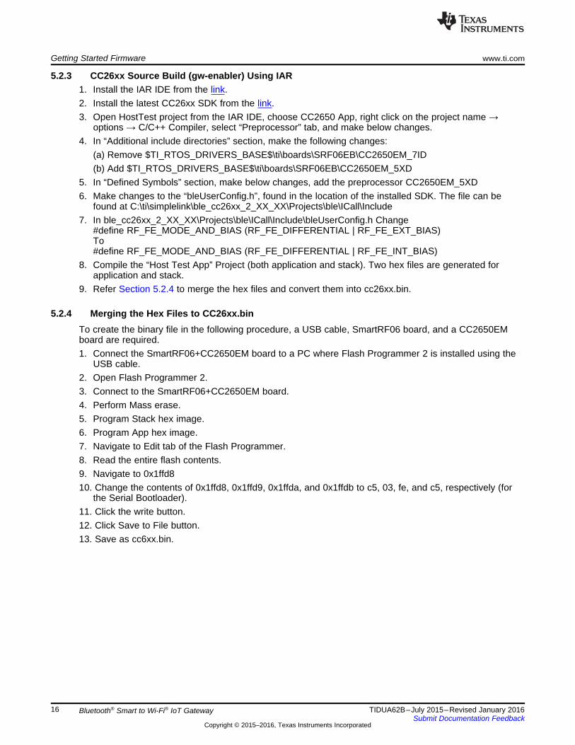
5.2.3 CC26xx Source Build (gw-enabler) Using IAR1. Install the IAR IDE from the link.2. Install the latest CC26xx SDK from the link.3. Open HostTest project from the IAR IDE, choose CC2650 App, right click on the project name →
options → C/C++ Compiler, select “Preprocessor” tab, and make below changes.4. In “Additional include directories” section, make the following changes:
(a) Remove $TI_RTOS_DRIVERS_BASE$\ti\boards\SRF06EB\CC2650EM_7ID(b) Add $TI_RTOS_DRIVERS_BASE$\ti\boards\SRF06EB\CC2650EM_5XD
5. In “Defined Symbols” section, make below changes, add the preprocessor CC2650EM_5XD6. Make changes to the “bleUserConfig.h”, found in the location of the installed SDK. The file can be
found at C:\ti\simplelink\ble_cc26xx_2_XX_XX\Projects\ble\ICall\Include7. In ble_cc26xx_2_XX_XX\Projects\ble\ICall\Include\bleUserConfig.h Change
#define RF_FE_MODE_AND_BIAS (RF_FE_DIFFERENTIAL | RF_FE_EXT_BIAS)To#define RF_FE_MODE_AND_BIAS (RF_FE_DIFFERENTIAL | RF_FE_INT_BIAS)
8. Compile the “Host Test App” Project (both application and stack). Two hex files are generated forapplication and stack.
9. Refer Section 5.2.4 to merge the hex files and convert them into cc26xx.bin.
5.2.4 Merging the Hex Files to CC26xx.binTo create the binary file in the following procedure, a USB cable, SmartRF06 board, and a CC2650EMboard are required.1. Connect the SmartRF06+CC2650EM board to a PC where Flash Programmer 2 is installed using the
USB cable.2. Open Flash Programmer 2.3. Connect to the SmartRF06+CC2650EM board.4. Perform Mass erase.5. Program Stack hex image.6. Program App hex image.7. Navigate to Edit tab of the Flash Programmer.8. Read the entire flash contents.9. Navigate to 0x1ffd810. Change the contents of 0x1ffd8, 0x1ffd9, 0x1ffda, and 0x1ffdb to c5, 03, fe, and c5, respectively (for
the Serial Bootloader).11. Click the write button.12. Click Save to File button.13. Save as cc6xx.bin.

Attempt Auto Connection
Start
Blink LED-2SLOW BLINK (1 per sec)
Enter Smartconfigmode for 10 secs
Switch ON LED-2
Is Auto
Connectionsuccessful?
No Indicator to user to start
Wi-Fi Starter app on mobile
Is
SmartConfig
Successful?
No Indicator to user that AP
connection didn’t happen.
Use CLI command
Yes
Make sure the desired AP
is switched ON
YesSwitch OFF LED-2
Indicator to the user that AP
connection is successful
www.ti.com Getting Started Firmware
17TIDUA62B–July 2015–Revised January 2016Submit Documentation Feedback
Copyright © 2015–2016, Texas Instruments Incorporated
Bluetooth® Smart to Wi-Fi® IoT Gateway
5.3 WLAN ConnectionThe gateway must be connected to a Wi-Fi Access Point (AP), which has cloud connectivity, to realize theIoT functionality. This Wi-Fi connection can also be used for HTTP configuration.
CC3200 maintains Wi-Fi Profiles, which helps in automatic connections to an AP during the boot up. Theuser should not need to make an AP connection in every power cycle.
Figure 10. WLAN Connection Process During Initialization

Getting Started Firmware www.ti.com
18 TIDUA62B–July 2015–Revised January 2016Submit Documentation Feedback
Copyright © 2015–2016, Texas Instruments Incorporated
Bluetooth® Smart to Wi-Fi® IoT Gateway
The AP connection may not be successful during the bootup due to one of these reasons:• No WLAN profile present• AP not switched on before the gatewayis reset• The Smartconfig application was not available or was not successful
Post initialization, use the CLI command (wlan_connect; refer to Section 6.1) to connect to the AP. Ensurethe AP is on while using this command. Upon successful connection, this configuration is stored as aWLAN profile. During subsequent power-cycles, this profile is checked if an auto connection is possible.
5.4 Bluetooth Smart Device ConnectionA Bluetooth Smart device can be connected to the gateway using various UI commands (Refer toSection 6). When connected, the device is paired with the gateway, and the subsequent power cycle ofthe gateway does not need a UI command to be entered for connection.
NOTE: Only Just Works bonding is supported, and no Passkey support is present while connectingto Bluetooth Smart devices.
The CLI commands to connect to a Bluetooth Smart device are scan and linke. Scan is used to scan thedevices that are advertising in the vicinity of BleFi. Linke connects to a desired device. The parameter ofthe linke command is the <scan id>.
For example,
G:>scan
.
.
G:>linke 0
5.4.1 Schema FileTypically, the characteristic in a Bluetooth Smart device is addressed using a handle. The handle is anumeric value and is not user friendly. The schema file mechanism in gateway maps the numeric handleto a human-readable string. This string can be used while monitoring the respective characteristic or whilechanging the value of the characteristic.
For example, to access the temperature data of the connected Bluetooth Smart Device,
G:>get 0 /Temp/Datais used instead ofG:>get 0 15Where 15 is the handle value.
NOTE: If schema file is not present, then default strings will be mapped (Example: char1).
To avail this facility, the user must create and download a schema file to the gateway. The schema fileformat is a human-readable JSON format and can be generated using any JSON editor. The SensorTagschema files in the package are created using https://www.jsoneditoronline.org/.
The name of the schema file is same as the device name that it publishes while advertising. An extension.sch must be added before downloading.Example: SensorTag.sch

{
"Service_1 UUID": [
{
"Service_1.Characteristic_1 UUID": " Service_1.Characteristic_1 Name"
},
{
“Service_1.Characteristic_2 UUID": " Service_1.Characteristic_2 Name"
},
….
….
….
],
"Service_2 UUID": [
{
"Service_2.Characteristic_1 UUID": " Service_2.Characteristic_1 Name"
},
{
“Service_2.Characteristic_2 UUID": " Service_2.Characteristic_2 Name"
},
….
….
….
],
….
….
….
}
www.ti.com Gateway Usage
19TIDUA62B–July 2015–Revised January 2016Submit Documentation Feedback
Copyright © 2015–2016, Texas Instruments Incorporated
Bluetooth® Smart to Wi-Fi® IoT Gateway
5.4.1.1 Schema File Format
6 Gateway UsageThis section assumes that the binaries are flashed in the gateway and the WLAN connection is alsosuccessful. For more information on the setup, refer to Section 4.3.
Typical gateway usage contains• WLAN connection• Connection to a Bluetooth Smart device• Data monitoring over MQTT/CLI/HTTP
The gateway can be controlled or monitored using the UIs (User Interfaces)• Command Line Interface (CLI) over UART• Message Queue Telemetry Transport (MQTT) from a remote client• Hypertext Transfer Protocol (HTTP) from a local machine
Gateway Usage www.ti.com
20 TIDUA62B–July 2015–Revised January 2016Submit Documentation Feedback
Copyright © 2015–2016, Texas Instruments Incorporated
Bluetooth® Smart to Wi-Fi® IoT Gateway
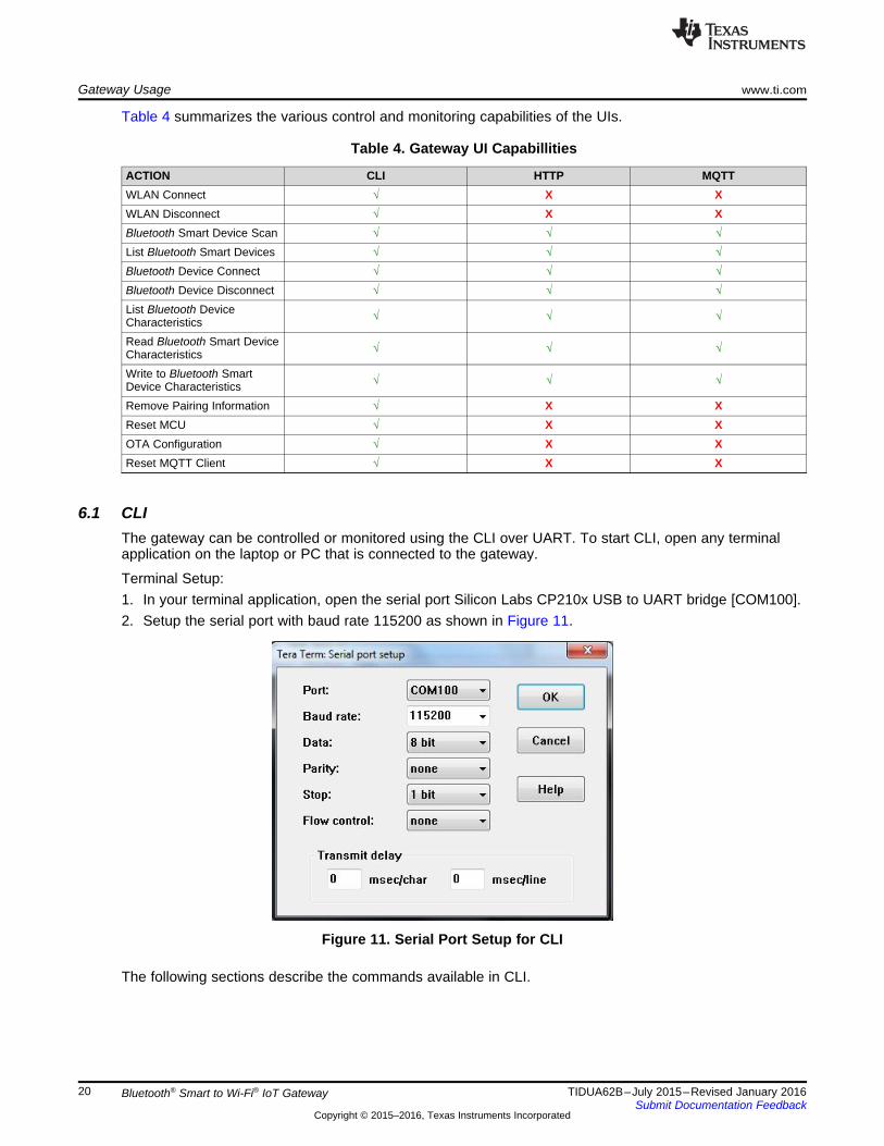
Table 4 summarizes the various control and monitoring capabilities of the UIs.
Table 4. Gateway UI Capabillities
ACTION CLI HTTP MQTTWLAN Connect √ X XWLAN Disconnect √ X XBluetooth Smart Device Scan √ √ √List Bluetooth Smart Devices √ √ √Bluetooth Device Connect √ √ √Bluetooth Device Disconnect √ √ √List Bluetooth DeviceCharacteristics √ √ √
Read Bluetooth Smart DeviceCharacteristics √ √ √
Write to Bluetooth SmartDevice Characteristics √ √ √
Remove Pairing Information √ X XReset MCU √ X XOTA Configuration √ X XReset MQTT Client √ X X
6.1 CLIThe gateway can be controlled or monitored using the CLI over UART. To start CLI, open any terminalapplication on the laptop or PC that is connected to the gateway.
Terminal Setup:1. In your terminal application, open the serial port Silicon Labs CP210x USB to UART bridge [COM100].2. Setup the serial port with baud rate 115200 as shown in Figure 11.
Figure 11. Serial Port Setup for CLI
The following sections describe the commands available in CLI.
NAME
scan
SYNOPSIS
scan
PARAMETERS
None
DESCRIPTION
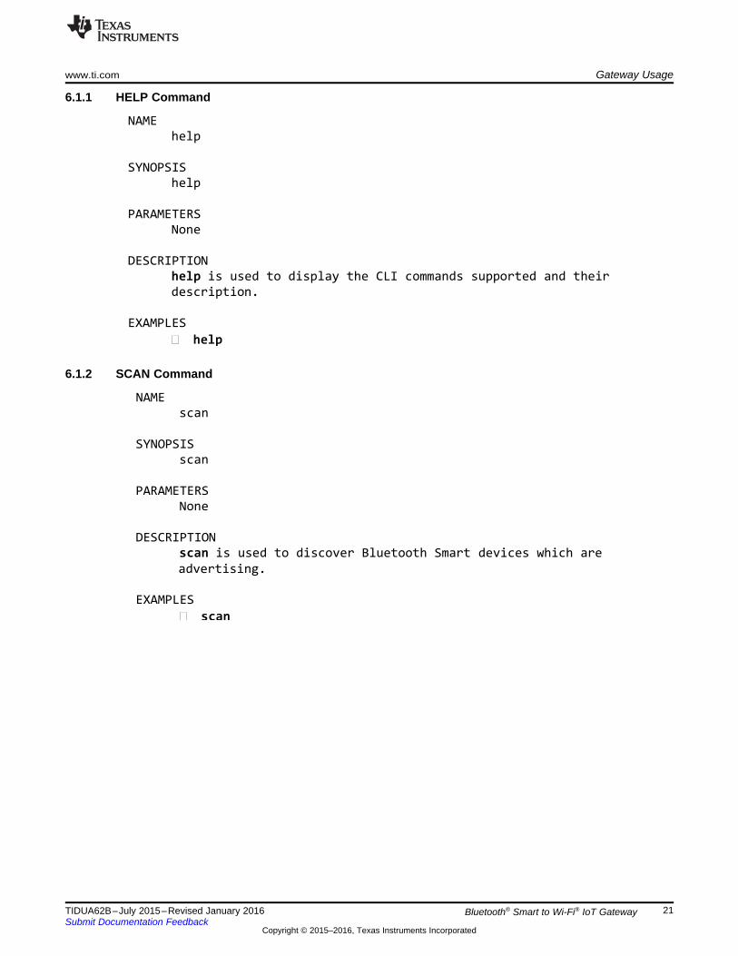
scan is used to discover Bluetooth Smart devices which are
EXAMPLES
� scan
advertising.
NAME
help
SYNOPSIS
help
PARAMETERS
None
DESCRIPTION
help is used to display the CLI commands supported and their
description.
EXAMPLES
� help
www.ti.com Gateway Usage
21TIDUA62B–July 2015–Revised January 2016Submit Documentation Feedback
Copyright © 2015–2016, Texas Instruments Incorporated
Bluetooth® Smart to Wi-Fi® IoT Gateway
6.1.1 HELP Command
6.1.2 SCAN Command

NAME
linke
SYNOPSIS
linke [device scan id]
PARAMETERS
[device scan id] – scan Id of the scanned Bluetooth Smart device
to be connected to. Please use the list command to find the scan
ID of the device
DESCRIPTION
linke is used to connect to one of the scanned Bluetooth Smart
EXAMPLES
� linke 1
devices.
NAME
list
SYNOPSIS
list
PARAMETERS
None
DESCRIPTION
list is used to list the scanned and connected Bluetooth
EXAMPLES
� list
Smart devices.
Gateway Usage www.ti.com
22 TIDUA62B–July 2015–Revised January 2016Submit Documentation Feedback
Copyright © 2015–2016, Texas Instruments Incorporated
Bluetooth® Smart to Wi-Fi® IoT Gateway
6.1.3 LIST Command
6.1.4 LINKE Command

NAME
listchar
SYNOPSIS
listchar [device connection id]
PARAMETERS
[device connection id] - – connection Id of the connected
Bluetooth Smart device to be list the characteristics. Please use
the command to know the connection ID of the device.list
DESCRIPTION
listchar is used to list the characteristics of one of the
connected Bluetooth Smart devices.
EXAMPLES
� listchar 0
NAME
linkt
SYNOPSIS
linkt [device connection id]
PARAMETERS
[device connection id] – connection Id of the connected Bluetooth
Smart device to be disconnected from. Please use the list command
to know the connection ID of the device.
DESCRIPTION
linkt is used to disconnect from one of the connected Bluetooth
EXAMPLES
� linkt 0
Smart devices
www.ti.com Gateway Usage
23TIDUA62B–July 2015–Revised January 2016Submit Documentation Feedback
Copyright © 2015–2016, Texas Instruments Incorporated
Bluetooth® Smart to Wi-Fi® IoT Gateway
6.1.5 LINKT Command
6.1.6 LISTCHAR Command

NAME
set
SYNOPSIS
set [device connection id] [Charstring]
[length of value in bytes] [value]
PARAMETERS
[device connection id] – connection Id of the connected Bluetooth
Smart device. Please use the list command to know the connection
ID of the device.
[Charstring] - Name of the characteristic to be set
length of value in bytes] – length of the value to be written in
bytes
[value] – value of the characteristic to be written
DESCRIPTION
set is used to write to the value of the characteristic of one of
the connected Bluetooth Smart devices.
EXAMPLES
� set 0 /Acc/Cfg 1 1
� set 0 char18 1 1
NAME
get
SYNOPSIS
get [device connection id] [Charstring]
PARAMETERS
[device connection id] – connection Id of the connected Bluetooth
Smart device. Please use the list command to know the connection
ID of the device.
[Charstring] - Name of the characteristic to be get
DESCRIPTION
get is used to read the value of the characteristic of one of the
connected Bluetooth Smart devices.
EXAMPLES
� get 0 /Acc/Data
� get 0 char18
Gateway Usage www.ti.com
24 TIDUA62B–July 2015–Revised January 2016Submit Documentation Feedback
Copyright © 2015–2016, Texas Instruments Incorporated
Bluetooth® Smart to Wi-Fi® IoT Gateway
6.1.7 GET Command
6.1.8 SET Command

NAME
wlan_disconnect
SYNOPSIS
wlan_disconnect
DESCRIPTION
wlan_disconnect is used to disconnect the WLAN connection to AP
PARAMETERS
None
EXAMPLES
� wlan_disconnect
NAME
wlan_connect
SYNOPSIS
wlan_connect [ssid] {key}
DESCRIPTION
wlan_connect is used to connect to an AP. Upon successfulconnection, a WLAN profile will be added. BleFi can be connectedto two kinds of AP
� Open
� WPAThe Open AP connection does not need the key parameter. If thekey parameter is present, then a WPA connection will be tried.
PARAMETERSssid – string value, ssid of the AP that the connection has to be
tried to.key – security password for AP connection (only in case of WPA)
EXAMPLES
� wlan_connect open_ap_1
� wlan_connect wpa_ap password123
www.ti.com Gateway Usage
25TIDUA62B–July 2015–Revised January 2016Submit Documentation Feedback
Copyright © 2015–2016, Texas Instruments Incorporated
Bluetooth® Smart to Wi-Fi® IoT Gateway
6.1.9 WLAN_CONNECT Command
6.1.10 WLAN_DISCONNECT Command

NAME
reset
SYNOPSIS
reset
PARAMETERS
None
DESCRIPTION
reset is used to reset the blefi.
EXAMPLES
� reset
NAME
mqttrst
SYNOPSIS
Mqttrst
PARAMETERS
None
DESCRIPTION
mqttrst is used to reset the mqtt client in blefi.
EXAMPLES
� mqttrst
Gateway Usage www.ti.com
26 TIDUA62B–July 2015–Revised January 2016Submit Documentation Feedback
Copyright © 2015–2016, Texas Instruments Incorporated
Bluetooth® Smart to Wi-Fi® IoT Gateway
6.1.11 MQTTRST Command
6.1.12 RESET Command

NAME
bleupdate
SYNOPSIS
bleupdate
PARAMETERS
None
DESCRIPTION
This command is used to update the CC26xx firmware. The update takes
effect after a reboot of blefi hardware.
EXAMPLES
� bleupdate
NAMEaddotameta
SYNOPSISaddotameta [metadatastring]
PARAMETERSmetadatastring – meta data string of the associated Dropboxaccount where the blefi OTA (Over The Air) files are stored.
DESCRIPTIONaddotameta is used to config the dropbox meta data string
information used for OTA in blefi.
EXAMPLES
� addotameta HNFGT_m-65YJJJADDGGGBs7y8FWDvgBAbnVFzVUdhDxhVJHu7ung9dSFsc_dHO45
www.ti.com Gateway Usage
27TIDUA62B–July 2015–Revised January 2016Submit Documentation Feedback
Copyright © 2015–2016, Texas Instruments Incorporated
Bluetooth® Smart to Wi-Fi® IoT Gateway
6.1.13 OTA Configuration Command
6.1.14 Bluetooth Smart Update Command
NAME
loaddefault
SYNOPSIS
loaddefault
PARAMETERS
None
DESCRIPTION
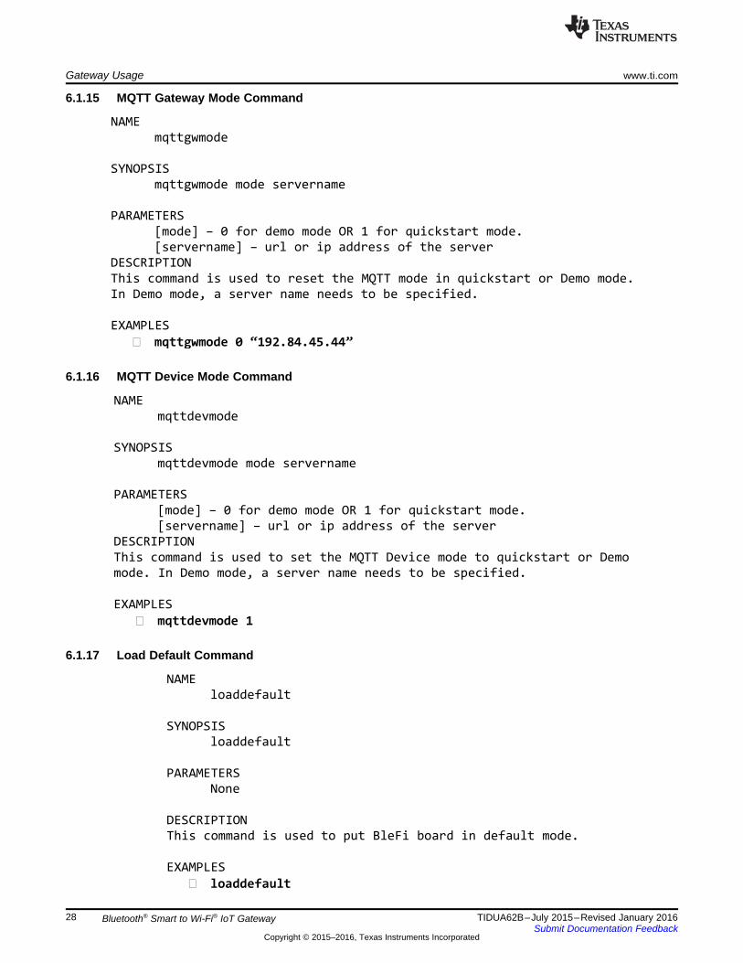
This command is used to put BleFi board in default mode.
EXAMPLES
� loaddefault
NAME
mqttdevmode
SYNOPSIS
mqttdevmode mode servername
PARAMETERS
[mode] – 0 for demo mode OR 1 for quickstart mode.
[servername] – url or ip address of the server
DESCRIPTION
This command is used to set the MQTT Device mode to quickstart or Demo
mode. In Demo mode, a server name needs to be specified.
EXAMPLES
� mqttdevmode 1
NAME
mqttgwmode
SYNOPSIS
mqttgwmode mode servername
PARAMETERS
[mode] – 0 for demo mode OR 1 for quickstart mode.
[servername] – url or ip address of the server
DESCRIPTION
This command is used to reset the MQTT mode in quickstart or Demo mode.
In Demo mode, a server name needs to be specified.
EXAMPLES
� mqttgwmode 0 “192.84.45.44”
Gateway Usage www.ti.com
28 TIDUA62B–July 2015–Revised January 2016Submit Documentation Feedback
Copyright © 2015–2016, Texas Instruments Incorporated
Bluetooth® Smart to Wi-Fi® IoT Gateway
6.1.15 MQTT Gateway Mode Command
6.1.16 MQTT Device Mode Command
6.1.17 Load Default Command

NAME
rmautocon
SYNOPSIS
rmautocon
PARAMETERS
None
DESCRIPTION
This command is used to disable the auto-connection privilege of a
previously connected BleFi device.
EXAMPLES
� unpair
NAME
autoconlist
SYNOPSIS
autoconlist
PARAMETERS
None
DESCRIPTION
This command is used to display the list of Bluetooth Smart
devices that are privileged to autoconnect with BleFi.
EXAMPLES
� pairlist
NAME
autoscan
SYNOPSIS
autoscan [Time in seconds]
PARAMETERS
Time in seconds. If less than 30, then autoscan will be disabled
DESCRIPTION
This command is used to set the autoscan duration of BleFi.
EXAMPLES
� autoscan 60
www.ti.com Gateway Usage
29TIDUA62B–July 2015–Revised January 2016Submit Documentation Feedback
Copyright © 2015–2016, Texas Instruments Incorporated
Bluetooth® Smart to Wi-Fi® IoT Gateway
6.1.18 Auto Scan Command
6.1.19 Display Auto-Connect List Command
6.1.20 Remove Auto Connection Command

NAME
triggerota
SYNOPSIS
triggerota
PARAMETERS
None
DESCRIPTION
This command is used to start the OTA process of the BleFi.
EXAMPLES
� triggerota
NAME
autocon
SYNOPSIS
autocon
PARAMETERS
1 or 0
DESCRIPTION
This command is used to enable or disable this feature in BleFi.EXAMPLES
� autocon 1
When enabled, a pre-connected Bluetooth Smart device will
automatically connect to BleFi.
Gateway Usage www.ti.com
30 TIDUA62B–July 2015–Revised January 2016Submit Documentation Feedback
Copyright © 2015–2016, Texas Instruments Incorporated
Bluetooth® Smart to Wi-Fi® IoT Gateway
6.1.21 Auto-Connect Command
6.1.22 Trigger OTA Command
6.2 MQTT—Enabling IoTMQTT (Message Queue Telemetry Transport) protocol is an extremely lightweight machine-to-machineconnectivity protocol. MQTT protocol is based on the publish-and-subscribe messaging model and isdesigned to be used on top of TCP / IP protocol.
The key point of this protocol includes small code footprint and low network bandwidth requirements.Other features include faster response time, low power requirement, and ease of scalability. All theseadvantages make it an ideal candidate for communication protocol in embedded devices intended toimplement IoT (internet of things) applications. More information regarding MQTT protocol can beobtained from the latest MQTT protocol specification.
A simple MQTT infrastructure contains a broker (like a central hub) connected to multiple clients, each ofwhich has the capability of publishing on any topic (token). The broker sends the message published onany topic to all the subscribers of that topic, as shown in Figure 12.
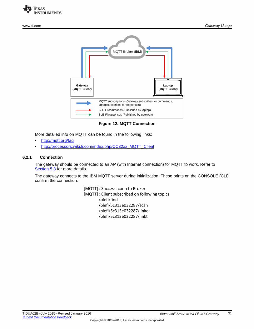
[MQTT] : Success: conn to Broker
[MQTT] : Client subscribed on following topics:
/blefi/find
/blefi/5c313e032287/scan
/blefi/5c313e032287/linke
/blefi/5c313e032287/linkt
MQTT Broker (IBM)
Gateway(MQTT Client)
Laptop(MQTT Client)
MQTT subscriptions (Gateway subscribes for commands, laptop subscribes for responses)
BLE-Fi commands (Published by laptop)
BLE-Fi responses (Published by gateway)
www.ti.com Gateway Usage
31TIDUA62B–July 2015–Revised January 2016Submit Documentation Feedback
Copyright © 2015–2016, Texas Instruments Incorporated
Bluetooth® Smart to Wi-Fi® IoT Gateway
Figure 12. MQTT Connection
More detailed info on MQTT can be found in the following links:• http://mqtt.org/faq• http://processors.wiki.ti.com/index.php/CC32xx_MQTT_Client
6.2.1 ConnectionThe gateway should be connected to an AP (with Internet connection) for MQTT to work. Refer toSection 5.3 for more details.
The gateway connects to the IBM MQTT server during initialization. These prints on the CONSOLE (CLI)confirm the connection.
Gateway Usage www.ti.com
32 TIDUA62B–July 2015–Revised January 2016Submit Documentation Feedback
Copyright © 2015–2016, Texas Instruments Incorporated
Bluetooth® Smart to Wi-Fi® IoT Gateway
If these prints do not appear on CONSOLE, one of the following issues may have occurred:• Gateway-AP connection is not successful• AP is not connected to internet• IBM MQTT server is not responding
NOTE: The 5c313e032287 is the MAC address of the gateway. This address is just an example andwill be different for different gateway devices.
6.2.2 MQTT ClientsThe gateway supports two kinds of MQTT clients: a gateway client and device clients. The gateway clientis created when the gateway powers up. By default, the gateway client is connected to an MQTT demoserver of IBM.
The device clients are created when a CC2650 SensorTag is connected to the gateway (over BluetoothSmart). There can be a maximum of 3 CC2650 SensorTag device clients. By default, the CC2650SensorTag device clients are connected to the QuickStart server of IBM®.
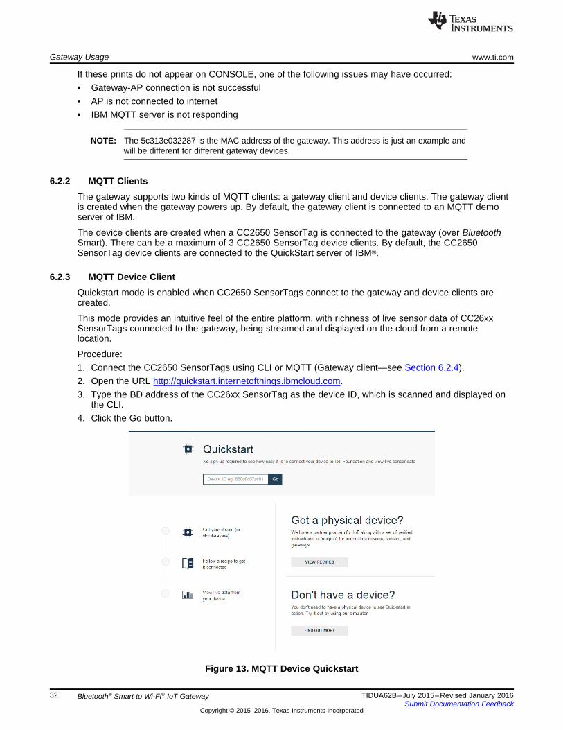
6.2.3 MQTT Device ClientQuickstart mode is enabled when CC2650 SensorTags connect to the gateway and device clients arecreated.
This mode provides an intuitive feel of the entire platform, with richness of live sensor data of CC26xxSensorTags connected to the gateway, being streamed and displayed on the cloud from a remotelocation.
Procedure:1. Connect the CC2650 SensorTags using CLI or MQTT (Gateway client—see Section 6.2.4).2. Open the URL http://quickstart.internetofthings.ibmcloud.com.3. Type the BD address of the CC26xx SensorTag as the device ID, which is scanned and displayed on
the CLI.4. Click the Go button.
Figure 13. MQTT Device Quickstart

www.ti.com Gateway Usage
33TIDUA62B–July 2015–Revised January 2016Submit Documentation Feedback
Copyright © 2015–2016, Texas Instruments Incorporated
Bluetooth® Smart to Wi-Fi® IoT Gateway
5. When connected, the device displays its status as “Connected” with the time.
Figure 14. Device Connected
6. The device also displays live sensor data of the connected CC26xx SensorTag.
6.2.4 MQTT Gateway ClientThe gateway acts as an MQTT client and connects to the messagesight.demos.ibm.com MQTT server. Toaccess the gateway, open an MQTT client from a laptop or PC and connect to the IBM MQTT server.1. Open an Internet browser (Chrome®, Internet Explorer™, Firefox®, or others)2. Go to this link: http://m2m.demos.ibm.com/mqttclient/3. Type messagesight.demos.ibm.com in the server text box and click Connect.

Gateway Usage www.ti.com
34 TIDUA62B–July 2015–Revised January 2016Submit Documentation Feedback
Copyright © 2015–2016, Texas Instruments Incorporated
Bluetooth® Smart to Wi-Fi® IoT Gateway
Figure 15. Remote Client Connection
4. When the connection is successful, the client can communicate with the gateway.5. Subscribe to desired topics one by one by typing the topic name and pressing Subscribe. For the list of
topics that the gateway publishes, refer to Section 6.2.6.
Figure 16. Remote Client Subscription
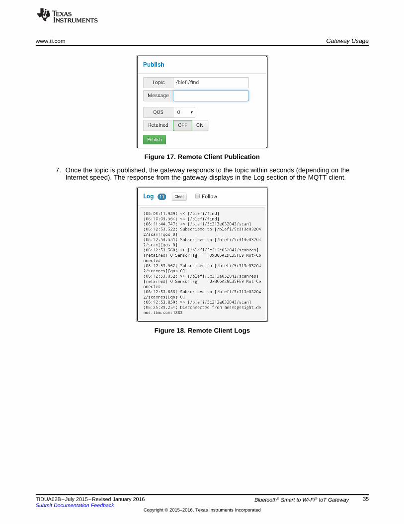
6. To send MQTT commands to the gateway, use the Publish section of the MQTT client. Enter the topicto be published and the parameter in the Message box, and press Publish. For the list of topics thatthe gateway responds to, refer to Section 6.2.6.
www.ti.com Gateway Usage
35TIDUA62B–July 2015–Revised January 2016Submit Documentation Feedback
Copyright © 2015–2016, Texas Instruments Incorporated
Bluetooth® Smart to Wi-Fi® IoT Gateway
Figure 17. Remote Client Publication
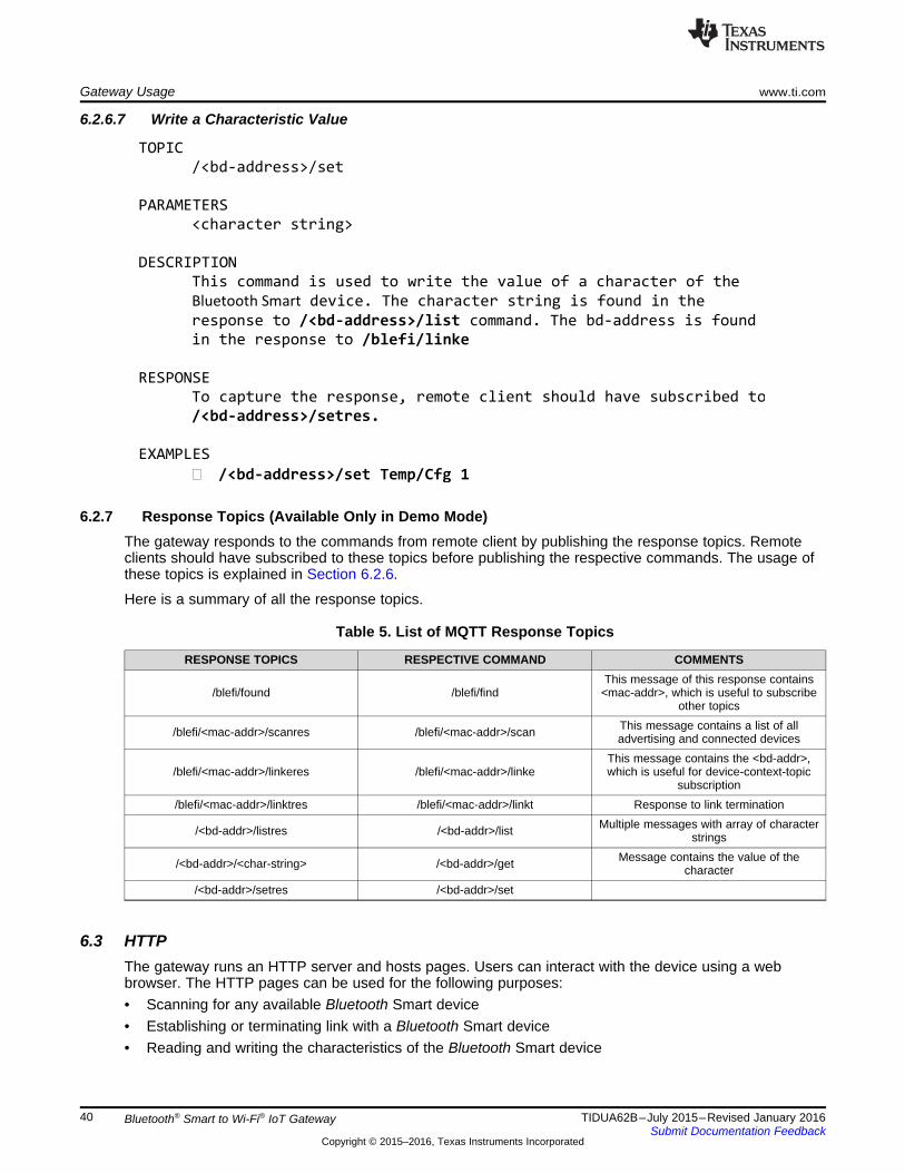
7. Once the topic is published, the gateway responds to the topic within seconds (depending on theInternet speed). The response from the gateway displays in the Log section of the MQTT client.
Figure 18. Remote Client Logs

Subscribe to command topics Subscribe to response topics
Connect to Server Connect to Server
Publish a command topic
with message parameters
Gateway receives the command
as it is already subscribed to it
The gateway processes the
command and prepares the
RESPONSE TOPIC
Publish the respective response
topic with message response
There may be one or more responses. Remote client receives the topic
and displays it to user
Gateway MQTTServer
Remote
Client
Gateway Usage www.ti.com
36 TIDUA62B–July 2015–Revised January 2016Submit Documentation Feedback
Copyright © 2015–2016, Texas Instruments Incorporated
Bluetooth® Smart to Wi-Fi® IoT Gateway
6.2.5 MQTT—Remote Access of the GatewayMQTT works on a subscription-publish mechanism. The gateway, as an MQTT client subscribes tonumerous topics. These subscribed topics act as a command to the gateway. A remote client may publishone of these topics with proper parameters as a command to the gateway. As a response to thecommand, the gateway publishes some topics. To receive the response, the remote client must havesubscribed to these topics. The below sequence diagram depicts the working of MQTT on the gateway.
Figure 19. MQTT Sequence Diagram
The gateway maintains two different contexts while connecting to the MQTT server. From external clientpoint of view, there is no difference while accessing the topics related to either of the contexts.1. Gateway Context (1 number)—This context is the default context and is created during initialization.
gateway context contains the topics that are related to gateway and not specific to a Bluetooth Smartdevice.
2. Device Context (0 to 3 numbers)—A device context is created when a Bluetooth Smart device getsconnected to the gateway. The maximum number of device contexts that can be created in thegateway is three.
6.2.6 Command Topics (Available Only in Demo Mode)The command topic is an MQTT topic subscribed by the gateway, and can be used by remote MQTTclients to command gateway.

TOPIC
/blefi/<mac-address>/scan
PARAMETERS
None
DESCRIPTION
This topic is used to scan the devices that are advertising in
the vicinity of BleFi indicated by <mac-address>.The mac-address
is found in the response to /blefi/find
RESPONSE
To capture the response, remote client should have subscribed to
/blefi/<mac-address>/scanres before publishing the command.
BleFi starts a scan process to find the devices that are
advertising in its vicinity.
Once the scan is complete, BleFi responds to this command by
publishing /blefi/<mac-address>/scanres topic. The message of the
response topic contains information of the Bluetooth Smart
devices scanned. This command is typically followed by
/blefi/<mac-address>/linke command.
EXAMPLES
� /blefi/<mac-address>/scan
TOPIC
/blefi/find
PARAMETERS
None
DESCRIPTION
This topic is used to find a BleFi device in the Cloud.
RESPONSE
To capture the response, remote client should have subscribed to
/blefi/found before publishing the command.
BleFi responds to this command by publishing /blefi/found topic,
with its mac-address. This mac-address is helpful in building
other topics, such as scan, linke and linkt.
EXAMPLES
� /blefi/find
www.ti.com Gateway Usage
37TIDUA62B–July 2015–Revised January 2016Submit Documentation Feedback
Copyright © 2015–2016, Texas Instruments Incorporated
Bluetooth® Smart to Wi-Fi® IoT Gateway
6.2.6.1 Find the Gateway Device
6.2.6.2 Scan Bluetooth Smart Devices

TOPIC
/blefi/<mac-address>/linkt
PARAMETERS
device-index
DESCRIPTION
This command is used to terminate a link between BleFi and
Bluetooth Smart device, indicated by the device-index.
RESPONSE
To capture the response, remote client should have subscribed to
/blefi/<mac-address>/linktres before publishing the command.
Once the link is terminated, BleFi responds to this command by
publishing /blefi/<mac-address>/linktres topic with success
indication.
Upon termination of link, BleFi deletes the “device-context” of
this device.
EXAMPLES
� /blefi/<mac-address>/linkt 0
TOPIC
/blefi/<mac-address>/linke
PARAMETERS
device-index
DESCRIPTION
This command is used to establish a link between BleFi and
Bluetooth Smart device, indicated by the device-index.
RESPONSE
To capture the response, remote client should have subscribed to
/blefi/<mac-address>/linkeres before publishing the command.
Once the link is successful, BleFi responds to this command by
publishing /blefi/<mac-address>/linkeres topic with success
indication.
Upon successful link establishment, BleFi creates a “device-
context” for this device.
This command is typically followed by /<bd-address>/list, <bd-
address> identifies the Bluetooth Smart device connected to BleFi.
EXAMPLES
� /blefi/<mac-address>/linke 1
Gateway Usage www.ti.com
38 TIDUA62B–July 2015–Revised January 2016Submit Documentation Feedback
Copyright © 2015–2016, Texas Instruments Incorporated
Bluetooth® Smart to Wi-Fi® IoT Gateway
6.2.6.3 Establish Link to a Bluetooth Smart Device
6.2.6.4 Terminate Bluetooth Smart Device Link

TOPIC/<bd-address>/get
PARAMETERS<character string>
DESCRIPTIONThis command is used to read the value of a character of the
Bluetooth Smart device. The character string is found in the
response to /<bd-address>/list command. The bd-address is found
in the response to /blefi/linke
RESPONSE
To capture the response, remote client should have subscribed tothe response to particular character (Ex: /<bd-
address>/Temp/Data) before publishing the command. The response
contains the value of the character
EXAMPLES
� /<bd-address>/get Temp/Data
TOPIC
/<bd-address>/list
PARAMETERS
None
DESCRIPTION
This command is used to list all the characteristics of a
connected Bluetooth Smart Device. The bd-address is found in the
response to /blefi/linke
RESPONSE
To capture the response, remote client should have subscribed to
/<bd-address>/listres before publishing the command. The response
lists all the characteristics of Bluetooth Smart device. The list is
an array of strings with the read/write permission enabled per
characteristic. The response would be fairly lengthy. This
command is typically followed by /<bd-address>/set or /<bd-
address>/get command
EXAMPLES
� /<bd-address>/list
www.ti.com Gateway Usage
39TIDUA62B–July 2015–Revised January 2016Submit Documentation Feedback
Copyright © 2015–2016, Texas Instruments Incorporated
Bluetooth® Smart to Wi-Fi® IoT Gateway
6.2.6.5 List Characteristics of Bluetooth Smart Device
6.2.6.6 Read Value of a Characteristic
TOPIC
/<bd-address>/set
PARAMETERS
<character string>
DESCRIPTION
This command is used to write the value of a character of the
Bluetooth Smart device. The character string is found in the
response to /<bd-address>/list command. The bd-address is found
in the response to /blefi/linke
RESPONSE
To capture the response, remote client should have subscribed to
/<bd-address>/setres.
EXAMPLES
� /<bd-address>/set Temp/Cfg 1
Gateway Usage www.ti.com
40 TIDUA62B–July 2015–Revised January 2016Submit Documentation Feedback
Copyright © 2015–2016, Texas Instruments Incorporated
Bluetooth® Smart to Wi-Fi® IoT Gateway
6.2.6.7 Write a Characteristic Value
6.2.7 Response Topics (Available Only in Demo Mode)The gateway responds to the commands from remote client by publishing the response topics. Remoteclients should have subscribed to these topics before publishing the respective commands. The usage ofthese topics is explained in Section 6.2.6.
Here is a summary of all the response topics.
Table 5. List of MQTT Response Topics
RESPONSE TOPICS RESPECTIVE COMMAND COMMENTS
/blefi/found /blefi/findThis message of this response contains
<mac-addr>, which is useful to subscribeother topics
/blefi/<mac-addr>/scanres /blefi/<mac-addr>/scan This message contains a list of alladvertising and connected devices
/blefi/<mac-addr>/linkeres /blefi/<mac-addr>/linkeThis message contains the <bd-addr>,which is useful for device-context-topic
subscription/blefi/<mac-addr>/linktres /blefi/<mac-addr>/linkt Response to link termination
/<bd-addr>/listres /<bd-addr>/list Multiple messages with array of characterstrings
/<bd-addr>/<char-string> /<bd-addr>/get Message contains the value of thecharacter
/<bd-addr>/setres /<bd-addr>/set
6.3 HTTPThe gateway runs an HTTP server and hosts pages. Users can interact with the device using a webbrowser. The HTTP pages can be used for the following purposes:• Scanning for any available Bluetooth Smart device• Establishing or terminating link with a Bluetooth Smart device• Reading and writing the characteristics of the Bluetooth Smart device

www.ti.com Gateway Usage
41TIDUA62B–July 2015–Revised January 2016Submit Documentation Feedback
Copyright © 2015–2016, Texas Instruments Incorporated
Bluetooth® Smart to Wi-Fi® IoT Gateway
6.3.1 Bluetooth Smart Dashboard1. The HTML pages are part of the installer. These pages should be downloaded onto SFLASH of the
gateway.2. Run the gateway application. When connected to the AP, the acquired IP is displayed in the CLI as
shown in Figure 20.
Figure 20. IP Address Displayed on CLI
3. Open the browser and type <ipaddr>/ble_dashboard.html• For example, type 192.168.1.100/ble_dashboard.html in browser URL field• Browser shows the Bluetooth Smart dashboard page
The Bluetooth Smart dashboard page contains two tabs:• Connection—Users can scan all the advertising Bluetooth Smart devices in the gateway vicinity using
this tab. This tab contains controls to establish and terminate link to a Bluetooth Smart device• Data—This tab is used to show all the characteristics of a connected Bluetooth Smart device. Based
on the permissions, the characteristic value can be read from or written to, using this tab

Gateway Usage www.ti.com
42 TIDUA62B–July 2015–Revised January 2016Submit Documentation Feedback
Copyright © 2015–2016, Texas Instruments Incorporated
Bluetooth® Smart to Wi-Fi® IoT Gateway
6.3.2 Bluetooth Smart Connection Page
Figure 21. Bluetooth Smart Dashboard Page
6.3.2.1 Scanning a Bluetooth Smart Device1. Select the Connection tab.2. Press the Scan button to start scanning for available Bluetooth Smart devices.3. Wait for 5 seconds for the command to be completed.4. Press the Refresh button to show the list of scanned devices.
6.3.2.2 Establishing Link with a Bluetooth Smart Device1. Among the list of scanned devices, Select the Radio Button of the desired Bluetooth Smart device.2. Press the Establish Link button.3. Wait for 5 seconds for the command to be completed.4. Press the Refresh button to show the list of connected devices.
www.ti.com Gateway Usage
43TIDUA62B–July 2015–Revised January 2016Submit Documentation Feedback
Copyright © 2015–2016, Texas Instruments Incorporated
Bluetooth® Smart to Wi-Fi® IoT Gateway
6.3.2.3 Terminating Link from a Bluetooth Smart Device1. Among the list of connected devices, Select the Radio Button of the desired Bluetooth Smart device.2. Press the Terminate Link button.3. Wait for 2 seconds for the command to be completed.4. Press Refresh button to show the updated list of connected devices.
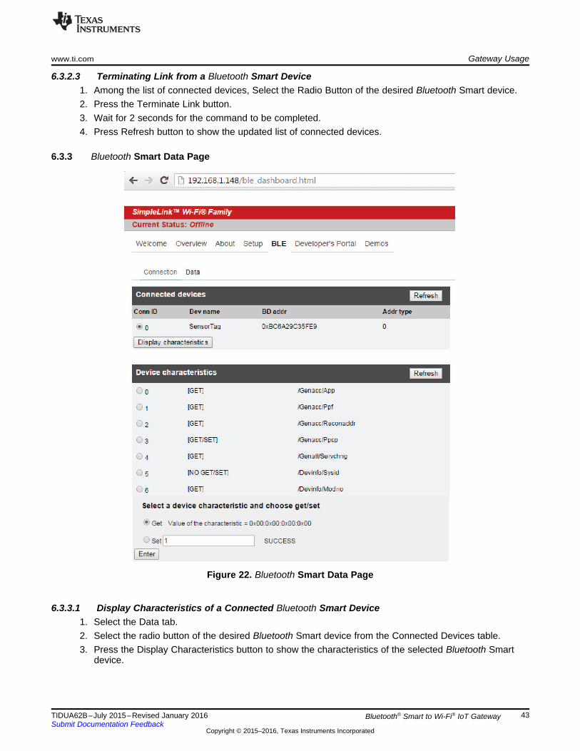
6.3.3 Bluetooth Smart Data Page
Figure 22. Bluetooth Smart Data Page
6.3.3.1 Display Characteristics of a Connected Bluetooth Smart Device1. Select the Data tab.2. Select the radio button of the desired Bluetooth Smart device from the Connected Devices table.3. Press the Display Characteristics button to show the characteristics of the selected Bluetooth Smart
device.

Gateway Usage www.ti.com
44 TIDUA62B–July 2015–Revised January 2016Submit Documentation Feedback
Copyright © 2015–2016, Texas Instruments Incorporated
Bluetooth® Smart to Wi-Fi® IoT Gateway
6.3.3.2 Read or Write Characteristic Value1. In the Device Characteristics table, select the radio button of the characteristic to be read or written.2. To read a characteristic, select the Get radio button and press the Enter button.3. The characteristic value read will be displayed adjacent to the Get button.4. To write to a characteristic value, select the Set radio button, enter the value to be written in the text
box adjacent to the Set button, and press the Enter button.5. If the write is completed successfully, the SUCCESS message is shown.
6.4 OTAThe Over-The-Air (OTA) update is the wireless delivery of new software updates and/or configurations toembedded devices and with the concept of Wireless Sensor Network and Internet of Things, OTA is anefficient way of distributing firmware updates or upgrades.
The application binary (blefi.bin) and the gateway enabler binary (cc26xx.bin) files can be updated overthe air (OTA). This feature requires the user to create a Dropbox account and load the files in the account.
6.4.1 Creating a Dropbox API Application1. Create an account with Dropbox and log in.2. Go to https://www.dropbox.com/developers/apps/create and choose Dropbox API app.3. Choose “Files and Datastores” and “Yes, my app only needs access to files it creates”.4. Provide a suitable name for the app and click the Create APP button.5. You will be redirected to Apps setting page. Scroll down to “Generated access token” and click
generate. Copy and save the generated token. This token needs to be stored in the gatewayusing the“otaconfig” command in CLI.
6. Go to https://www.dropbox.com/home/Apps.7. Click on the application name.8. Create a new folder and name it in the following format: TI_BleFi_v<version number> (for example:
TI_BleFi_v01). The version name is found on the CLI Banner.
Figure 23. CLI Banner Showing Version Number
9. Rename “blefi.bin” as “f80_sys_mcuimgA.bin”. Rename “ble_gateway_enabler.bin” as “f80_cc26xx.bin”and copy these files to the newly created folder in the Dropbox account.
10. Power on the gateway, then connect to an AP (that has internet access) after initialization.11. “Waiting for OTA Trigger” on the CONSOLE indicates that the OTA can be performed.12. Press the BTN-1 to start the OTA process.13. Once the OTA download is completed, the gateway restarts itself.

www.ti.com Test Data
45TIDUA62B–July 2015–Revised January 2016Submit Documentation Feedback
Copyright © 2015–2016, Texas Instruments Incorporated
Bluetooth® Smart to Wi-Fi® IoT Gateway
7 Test DataThis section describes the tests performed on the gateway.
7.1 CLI Snapshot
Figure 24. CLI Snapshot
Test Data www.ti.com
46 TIDUA62B–July 2015–Revised January 2016Submit Documentation Feedback
Copyright © 2015–2016, Texas Instruments Incorporated
Bluetooth® Smart to Wi-Fi® IoT Gateway
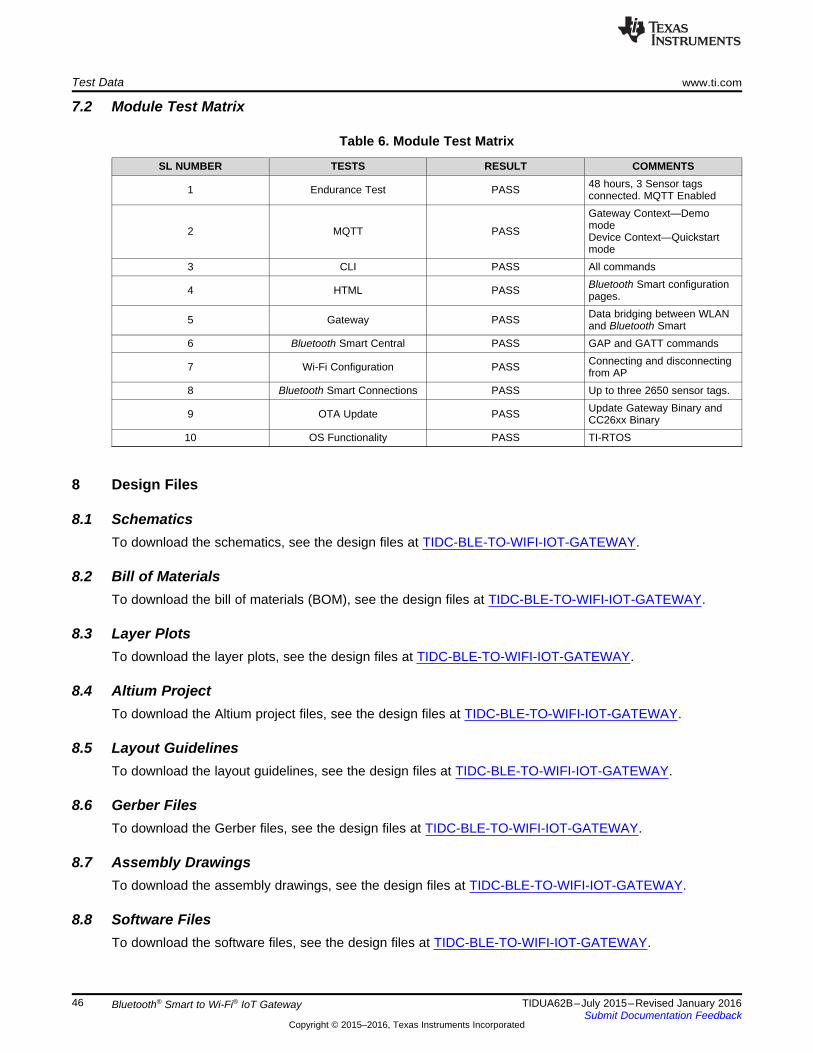
7.2 Module Test Matrix
Table 6. Module Test Matrix
SL NUMBER TESTS RESULT COMMENTS
1 Endurance Test PASS 48 hours, 3 Sensor tagsconnected. MQTT Enabled
2 MQTT PASS
Gateway Context—DemomodeDevice Context—Quickstartmode
3 CLI PASS All commands
4 HTML PASS Bluetooth Smart configurationpages.
5 Gateway PASS Data bridging between WLANand Bluetooth Smart
6 Bluetooth Smart Central PASS GAP and GATT commands
7 Wi-Fi Configuration PASS Connecting and disconnectingfrom AP
8 Bluetooth Smart Connections PASS Up to three 2650 sensor tags.
9 OTA Update PASS Update Gateway Binary andCC26xx Binary
10 OS Functionality PASS TI-RTOS
8 Design Files
8.1 SchematicsTo download the schematics, see the design files at TIDC-BLE-TO-WIFI-IOT-GATEWAY.
8.2 Bill of MaterialsTo download the bill of materials (BOM), see the design files at TIDC-BLE-TO-WIFI-IOT-GATEWAY.
8.3 Layer PlotsTo download the layer plots, see the design files at TIDC-BLE-TO-WIFI-IOT-GATEWAY.
8.4 Altium ProjectTo download the Altium project files, see the design files at TIDC-BLE-TO-WIFI-IOT-GATEWAY.
8.5 Layout GuidelinesTo download the layout guidelines, see the design files at TIDC-BLE-TO-WIFI-IOT-GATEWAY.
8.6 Gerber FilesTo download the Gerber files, see the design files at TIDC-BLE-TO-WIFI-IOT-GATEWAY.
8.7 Assembly DrawingsTo download the assembly drawings, see the design files at TIDC-BLE-TO-WIFI-IOT-GATEWAY.
8.8 Software FilesTo download the software files, see the design files at TIDC-BLE-TO-WIFI-IOT-GATEWAY.

www.ti.com References
47TIDUA62B–July 2015–Revised January 2016Submit Documentation Feedback
Copyright © 2015–2016, Texas Instruments Incorporated
Bluetooth® Smart to Wi-Fi® IoT Gateway
9 References
1. CC3200 SimpleLink™ Wi-Fi® and Internet-of-Things solution, a Single-Chip Wireless MCU (CC3200)2. SimpleLink™ multi-standard 2.4 GHz ultra-low power wireless MCU (CC2650)3. Ultralow-Noise, High PSRR, Fast, RF, 1-A Low-Dropout Linear Regulators (TPS79601)4. 2-Channel ESD Solution for SuperSpeed USB 3.0 Interface (TPD2EUSB30)5. Silabs: USB to UART Bridge (http://www.silabs.com/products/interface/usbtouart/Pages/usb-to-uart-
bridge.aspx)

About the Author www.ti.com
48 TIDUA62B–July 2015–Revised January 2016Submit Documentation Feedback
Copyright © 2015–2016, Texas Instruments Incorporated
Bluetooth® Smart to Wi-Fi® IoT Gateway
10 About the AuthorSREEHARSHA SRINIVAS Applications Manager, LPRF, Texas Instruments.
VIJAYSARATHY SHASTRI Applications Lead, LPRF, Texas Instruments.

www.ti.com Revision History
49TIDUA62B–July 2015–Revised January 2016Submit Documentation Feedback
Copyright © 2015–2016, Texas Instruments Incorporated
Revision History
Revision History
Changes from A Revision (September 2015) to B Revision .......................................................................................... Page
• Updated Block Diagram .................................................................................................................. 3
NOTE: Page numbers for previous revisions may differ from page numbers in the current version.

IMPORTANT NOTICE FOR TI REFERENCE DESIGNS
Texas Instruments Incorporated ("TI") reference designs are solely intended to assist designers (“Buyers”) who are developing systems thatincorporate TI semiconductor products (also referred to herein as “components”). Buyer understands and agrees that Buyer remainsresponsible for using its independent analysis, evaluation and judgment in designing Buyer’s systems and products.TI reference designs have been created using standard laboratory conditions and engineering practices. TI has not conducted anytesting other than that specifically described in the published documentation for a particular reference design. TI may makecorrections, enhancements, improvements and other changes to its reference designs.Buyers are authorized to use TI reference designs with the TI component(s) identified in each particular reference design and to modify thereference design in the development of their end products. HOWEVER, NO OTHER LICENSE, EXPRESS OR IMPLIED, BY ESTOPPELOR OTHERWISE TO ANY OTHER TI INTELLECTUAL PROPERTY RIGHT, AND NO LICENSE TO ANY THIRD PARTY TECHNOLOGYOR INTELLECTUAL PROPERTY RIGHT, IS GRANTED HEREIN, including but not limited to any patent right, copyright, mask work right,or other intellectual property right relating to any combination, machine, or process in which TI components or services are used.Information published by TI regarding third-party products or services does not constitute a license to use such products or services, or awarranty or endorsement thereof. Use of such information may require a license from a third party under the patents or other intellectualproperty of the third party, or a license from TI under the patents or other intellectual property of TI.TI REFERENCE DESIGNS ARE PROVIDED "AS IS". TI MAKES NO WARRANTIES OR REPRESENTATIONS WITH REGARD TO THEREFERENCE DESIGNS OR USE OF THE REFERENCE DESIGNS, EXPRESS, IMPLIED OR STATUTORY, INCLUDING ACCURACY ORCOMPLETENESS. TI DISCLAIMS ANY WARRANTY OF TITLE AND ANY IMPLIED WARRANTIES OF MERCHANTABILITY, FITNESSFOR A PARTICULAR PURPOSE, QUIET ENJOYMENT, QUIET POSSESSION, AND NON-INFRINGEMENT OF ANY THIRD PARTYINTELLECTUAL PROPERTY RIGHTS WITH REGARD TO TI REFERENCE DESIGNS OR USE THEREOF. TI SHALL NOT BE LIABLEFOR AND SHALL NOT DEFEND OR INDEMNIFY BUYERS AGAINST ANY THIRD PARTY INFRINGEMENT CLAIM THAT RELATES TOOR IS BASED ON A COMBINATION OF COMPONENTS PROVIDED IN A TI REFERENCE DESIGN. IN NO EVENT SHALL TI BELIABLE FOR ANY ACTUAL, SPECIAL, INCIDENTAL, CONSEQUENTIAL OR INDIRECT DAMAGES, HOWEVER CAUSED, ON ANYTHEORY OF LIABILITY AND WHETHER OR NOT TI HAS BEEN ADVISED OF THE POSSIBILITY OF SUCH DAMAGES, ARISING INANY WAY OUT OF TI REFERENCE DESIGNS OR BUYER’S USE OF TI REFERENCE DESIGNS.TI reserves the right to make corrections, enhancements, improvements and other changes to its semiconductor products and services perJESD46, latest issue, and to discontinue any product or service per JESD48, latest issue. Buyers should obtain the latest relevantinformation before placing orders and should verify that such information is current and complete. All semiconductor products are soldsubject to TI’s terms and conditions of sale supplied at the time of order acknowledgment.TI warrants performance of its components to the specifications applicable at the time of sale, in accordance with the warranty in TI’s termsand conditions of sale of semiconductor products. Testing and other quality control techniques for TI components are used to the extent TIdeems necessary to support this warranty. Except where mandated by applicable law, testing of all parameters of each component is notnecessarily performed.TI assumes no liability for applications assistance or the design of Buyers’ products. Buyers are responsible for their products andapplications using TI components. To minimize the risks associated with Buyers’ products and applications, Buyers should provideadequate design and operating safeguards.Reproduction of significant portions of TI information in TI data books, data sheets or reference designs is permissible only if reproduction iswithout alteration and is accompanied by all associated warranties, conditions, limitations, and notices. TI is not responsible or liable forsuch altered documentation. Information of third parties may be subject to additional restrictions.Buyer acknowledges and agrees that it is solely responsible for compliance with all legal, regulatory and safety-related requirementsconcerning its products, and any use of TI components in its applications, notwithstanding any applications-related information or supportthat may be provided by TI. Buyer represents and agrees that it has all the necessary expertise to create and implement safeguards thatanticipate dangerous failures, monitor failures and their consequences, lessen the likelihood of dangerous failures and take appropriateremedial actions. Buyer will fully indemnify TI and its representatives against any damages arising out of the use of any TI components inBuyer’s safety-critical applications.In some cases, TI components may be promoted specifically to facilitate safety-related applications. With such components, TI’s goal is tohelp enable customers to design and create their own end-product solutions that meet applicable functional safety standards andrequirements. Nonetheless, such components are subject to these terms.No TI components are authorized for use in FDA Class III (or similar life-critical medical equipment) unless authorized officers of the partieshave executed an agreement specifically governing such use.Only those TI components that TI has specifically designated as military grade or “enhanced plastic” are designed and intended for use inmilitary/aerospace applications or environments. Buyer acknowledges and agrees that any military or aerospace use of TI components thathave not been so designated is solely at Buyer's risk, and Buyer is solely responsible for compliance with all legal and regulatoryrequirements in connection with such use.TI has specifically designated certain components as meeting ISO/TS16949 requirements, mainly for automotive use. In any case of use ofnon-designated products, TI will not be responsible for any failure to meet ISO/TS16949.IMPORTANT NOTICE
Mailing Address: Texas Instruments, Post Office Box 655303, Dallas, Texas 75265Copyright © 2016, Texas Instruments Incorporated