three-dimensional finite element analysis of the ... · the superimposed contours of displacements...
TRANSCRIPT
ORIGINAL ARTICLE
Three-dimensional finite element analysis of thecraniomaxillary complex during maxillaryprotraction with bone anchorage vs conventionaldental anchorage
Xiulin Yan,a Weijun He,b Tao Lin,b Jun Liu,c Xiaofeng Bai,d Guangqi Yan,d and Li Lue
Shenyang, Liaoning, China
aAssoMedicbPostencescAssoLiaondLectuChinaeProfeassocLiaonThe aucts oReprinof StoDistriSubm0889-Copyrhttp:/
Introduction: The aim of this study was to explore the biomechanical effects on the craniomaxillary complex ofbone anchorage and dental anchorage during maxillary protraction. Methods: We established 2 finite elementmodels. One simulatedmaxillary protraction with dental anchorage in themaxillary first molars and the other withbone anchorage in the infrazygomatic buttresses of the maxilla. The magnitude of the applied forces was 500 gper side, and the force directions were 0�, 10�, 20�, and 30� forward and downward relative to the occlusal plane.Results: The finite element model of the craniomaxillary complex could displace in an almost translatorymannerwhen the force direction was about 20� in the bone anchorage model and about 30� in the dental anchoragemodel. The nodes representing the sutures at the back of the maxilla showed greater stress in the bone anchor-age model than in the dental anchorage model in the same force direction. It is the opposite at the front of themaxilla. Conclusions: We should determine the direction of applied force according to the anchorage locationand skeletal characteristics of patients before maxillary protraction. The dramatic effects of maxillary protractionwith bone anchorage can be based on the advantages of bone anchorage, not on the changes in the region of theapplied force. (Am J Orthod Dentofacial Orthop 2013;143:197-205)
Conventional treatment for a Class III malocclusionwithmaxillary deficiency often usesmaxillary pro-traction with an intraoral appliance and a face-
mask, especially at early ages. Some investigations havedemonstrated the skeletal and dentoalveolar effectsof this conventional dental anchorage appliance in ashort-term treatment, including forward displacementof the maxilla, clockwise rotation of the mandible, pro-trusion of the maxillary incisors, and retrusion of the
ciate professor, Department of Orthodontics, School of Stomatology, Chinaal University, Shenyang, Liaoning, China.graduate student, Institute of Metal Research, Chinese Academy of Sci-, Shenyang, Liaoning, China.ciate professor, School of Science, Northeastern University, Shenyang,ing, China.rer, Department of Oral and Maxillofacial Surgery, School of Stomatology,Medical University, Shenyang, Liaoning, China.ssor and chairman, Department of Oral and Maxillofacial Surgery;iate director, School of Stomatology, China Medical University, Shenyang,ing, China.uthors report no commercial, proprietary, or financial interest in the prod-r companies described in this article.t requests to: Li Lu, Department of Oral and Maxillofacial Surgery, Schoolmatology, China Medical University, 117# Nanjing North Street, Hepingct, Shenyang, Liaoning, China, 110002; e-mail, [email protected], November 2011; revised and accepted, September 2012.5406/$36.00ight � 2013 by the American Association of Orthodontists./dx.doi.org/10.1016/j.ajodo.2012.09.019
mandibular incisors.1-4 However, the skeletal effects ofmaxillary protraction are still controversial.5 In somelong-term follow-ups, there were no significantbetween-group differences in skeletal changes, com-pared with a control group under the same conditions.6,7
To improve the skeletal effects, osseointegrated im-plants,8 orthodontic miniscrews,9 and miniplates10
have been substituted for conventional dental anchor-age and used as bone anchorage in maxillary protrac-tion. Several studies have demonstrated the dramaticskeletal effects of maxillary protraction by using boneanchorage, especially with titanium miniplates in the in-frazygomatic buttresses of the maxilla.11-14 However,there are great discrepancies in the locations of im-plants and the directions of orthopedic forces in thesestudies, and no study provides enough evidence forchoosing them.13,14
The locations of the implants and the direction of theorthopedic forces are important in the displacement andstress distribution of the maxilla during maxillary pro-traction and thus affect the prognosis of patients witha skeletal Class III malocclusion.15 A 3-dimensional finiteelement model could simulate maxillary protraction andpredict the results of the displacement and the stress dis-tribution of craniomaxillary complex.16-18 It might be
197

Table. Young's modulus and Poisson's ratio for thematerials used in this study (Iseri et al,19 Jafariet al,20 Pan et al,21 and Lee and Baek22)
Material Young's modulus (kg/mm2) Poisson's ratioCompact bone 1.37 3 104 0.3Cancellous bone 7.9 3 103 0.3Tooth 2.0 3 104 0.3Miniscrew 1.05 3 105 0.33
198 Yan et al
helpful to improve the curative effects of maxillaryprotraction.
The aims of this study were to use the finite elementmethod to investigate displacement and stress distribu-tion in the craniomaxillary complex when bone anchor-age is used in the infrazygomatic buttresses of themaxilla under different loading conditions during max-illary protraction and to compare them with the resultsof maxillary first molar anchorage.
MATERIAL AND METHODS
Spiral computed tomography images (SomatonLightspeed/64 Plus; GE Healthcare, Waukesha, Wis) ofthe craniofacial complex region (0.5-mm layer; voxelsize, 0.44 3 0.44 3 0.5 mm3) were obtained. The scandata were from a 12-year-old boy with a mandibularfracture; informed consent was obtained from the pa-tient and his parents. The data were saved as digital im-aging and communications in medicine (DICOM) filesand then imported into Mimics software (Materialise,Leuven, Belgium) for 3-dimensional reconstruction.Hounsfield unit values from 226 to 3071 were used toidentify and distinguish the craniofacial bone from othertissues. Once the craniomaxillary complex was identi-fied, other bone sections were segmented by removingevery pixel from each slice in the data set. The recon-structed geometry of craniomaxillary complex was ex-ported in STL1file format as the geometric model withdental anchorage. This geometry was then mergedwith 3 cylinders (radius, 2 mm; length, 5 mm; made bythe Mimics software) that simulated the miniscrews ateach side of the infrazygomatic buttresses of the maxilla.The merged geometry was exported in STL1file formatas the geometric model with bone anchorage.
The STL1file was imported into MSC.Marc (MSCSoftware, Santa Ana, Calif), which was used to generatea volume mesh from the 3-dimensional geometry of thecraniomaxillary complex. The model with dental anchor-age was meshed into 1,502,391 hexahedral elements(C3D8) and 1,764,020 nodes, and the model with boneanchorage was meshed into 1,901,821 hexahedral ele-ments (C3D8R) and 2,239,849 nodes.
The meshed models were exported into Abaqussoftware (Abaqus, Providence, RI). The mechanical prop-erties of the compact and cancellous bones, teeth, andminiscrews in this model were defined according to ex-perimental data from previous studies (Table). The mate-rials in the analysis were assumed to be linearly elasticand isotropic.19-22 An encastre boundary condition wasimposed on the nodes along the foramen magnum.
We established 2 finite element models in this study.One model simulated maxillary protraction with dental
February 2013 � Vol 143 � Issue 2 American
anchorage in the maxillary first molars.23-25 In thismodel, a 500-g force per side forward and downwardrelative to the occlusal plane was directed about 2 mmsuperior to the border of the alveolar ridge betweenthe medial and distal aspects on the first molar. The an-gles between the force vector and occlusal plane were 0�,10�, 20�, and 30�, respectively. Another model simulatedmaxillary protraction with bone anchorage in the infra-zygomatic buttresses of the maxilla by using titaniumminiscrews.10-13 In the second model, a 500-g forceper side was applied to the miniscrews in the infrazygo-matic buttresses of the maxilla with angles between theforce vector and the occlusal plane of 0�, 10�, 20�, and30�, respectively (Fig 1).
The superimposed contours of displacements weregenerated by the Abaqus software automatically whenthe superimposition button was chosen. The unde-formed model (without applied force) was at the bottomand the deformed model (with applied force) was on itaccording to the 3-dimensional coordinates. All ana-tomic structures were a best-fit superimposition, sincea 3-dimensional finite element model was generatedunder a 3-dimensional coordinate system. To make thedeformation of the 3-dimensional models seen directly,the same local 3-dimensional coordinate system andamplification coefficient were set.
To measure the amount of displacement of the cra-niomaxillary complex, we selected some representativenodes in the frontal and sagittal planes. The displace-ment in the transverse plane was not analyzed, sincethe applied force was symmetrical in this plane. In thefrontal plane, the vertical displacement of the complexwas analyzed by measuring at 4 marker nodes, includingthe anterior nasal spine and the posterior nasal spine inthe palatal plane and the maxillary incisor and the firstmolar's palatal cusp tip in the occlusal plane. Then thelines were drawn by the nodes of the anterior nasal spine,the posterior nasal spine, the maxillary incisor, and thefirst molar's palatal cusp tip in the force vector directionsof 0�, 10�, 20�, and 30� in both finite element methodmodels, respectively. In the sagittal plane, we measured6 nodes at the front of the complex that might affect thepatient’s profile. Among these nodes, subspinale and
Journal of Orthodontics and Dentofacial Orthopedics

Fig 1. Two finite element models simulating maxillary protraction with bone anchorage and dental an-chorage in the force vector direction of 30�:A, the front of the finite element model with bone anchorage;B, the lateral view of the finite element model with bone anchorage; C, the lateral view of the finiteelement model with dental anchorage.
Yan et al 199
maxillary incisor represent the characteristics of the den-tition and the alveolar bone, and anterior nasal spine, in-ferior part of the nasal bone, nosewing, and nasionrepresent the skeletal characteristics of the craniomaxil-lary complex. The lines were also drawn by the above 6nodes in the force vector directions of 0�, 10�, 20�,and 30� in both finite element models, respectively. Inaddition, we chose the nodes at the midpoints of thetemporozygomatic, zygomaticomaxillary, and pterygo-palatine sutures at the back of the complex and the no-des of nasion and right nosewing at the front of thecomplex for measuring stress distribution.
RESULTS
In the superimposed contours of displacements, thecraniomaxillary complex in both finite element modelsexperienced counterclockwise rotation after the applica-tion of force, with an angle between the force vector andthe occlusal plane from 0� to 10� forward and downwardrelative to the occlusal plane. In the force vector direc-tion of 20�, the complex still showed counterclockwiserotation in the dental anchorage model but moved al-most without rotation in the bone anchorage model.In the force vector direction of 30�, the complex showedvisible clockwise rotation in the bone anchorage model
American Journal of Orthodontics and Dentofacial Orthoped
and displaced in an almost no-rotation pattern in thedental anchorage model (Fig 2).
Both finite element models displaced upward in theforce vector direction of 0�. In the force vector directionof 10�, all selected nodes in the dental anchorage modelstill displaced upward; however, the nodes standing forthe maxillary incisor and anterior nasal spine in thebone anchorage model moved upward, and those stand-ing for the posterior nasal spine and first molar's palatalcusp tip moved downward. In the force vector directionof 20�, all selected nodes in the bone anchorage modeldisplaced slightly downward, and the 4 lines drawn bythe nodes nearly formed an intersection. For the dentalanchorage model, the nodes of the maxillary central in-cisor and anterior nasal spine moved upward, and thoseof the posterior nasal spine and first molar's palatal cusptip moved downward. In the force vector direction of30�, the nodes in both models displaced downward,and the 4 lines drawn by the nodes nearly formed an in-tersection in the dental anchorage model (Fig 3).
In the force vector direction from 0� to 20�, the se-lected nodes in both finite elementmodels at the anteriorpart of the craniomaxillary complexes displaced forward;the amount of displacement decreased gradually, andthe nodes moved more in the dental anchorage modelthan in the bone anchorage model. The 2 lines drawn
ics February 2013 � Vol 143 � Issue 2
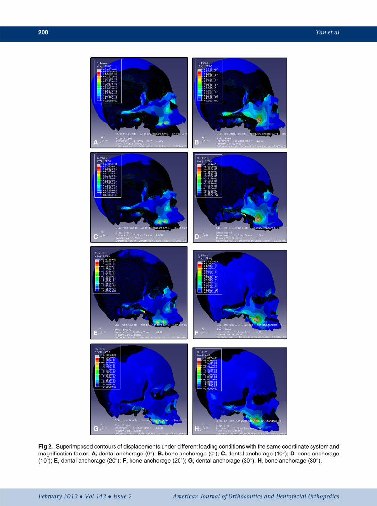
Fig 2. Superimposed contours of displacements under different loading conditions with the same coordinate system andmagnification factor: A, dental anchorage (0�); B, bone anchorage (0�); C, dental anchorage (10�); D, bone anchorage(10�); E, dental anchorage (20�); F, bone anchorage (20�); G, dental anchorage (30�); H, bone anchorage (30�).
200 Yan et al
February 2013 � Vol 143 � Issue 2 American Journal of Orthodontics and Dentofacial Orthopedics
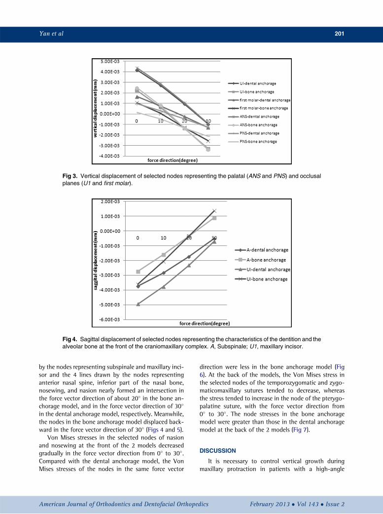
Fig 3. Vertical displacement of selected nodes representing the palatal (ANS and PNS) and occlusalplanes (U1 and first molar).
Fig 4. Sagittal displacement of selected nodes representing the characteristics of the dentition and thealveolar bone at the front of the craniomaxillary complex. A, Subspinale; U1, maxillary incisor.
Yan et al 201
by the nodes representing subspinale and maxillary inci-sor and the 4 lines drawn by the nodes representinganterior nasal spine, inferior part of the nasal bone,nosewing, and nasion nearly formed an intersection inthe force vector direction of about 20� in the bone an-chorage model, and in the force vector direction of 30�
in the dental anchorage model, respectively. Meanwhile,the nodes in the bone anchorage model displaced back-ward in the force vector direction of 30� (Figs 4 and 5).
Von Mises stresses in the selected nodes of nasionand nosewing at the front of the 2 models decreasedgradually in the force vector direction from 0� to 30�.Compared with the dental anchorage model, the VonMises stresses of the nodes in the same force vector
American Journal of Orthodontics and Dentofacial Orthoped
direction were less in the bone anchorage model (Fig6). At the back of the models, the Von Mises stress inthe selected nodes of the temporozygomatic and zygo-maticomaxillary sutures tended to decrease, whereasthe stress tended to increase in the node of the pterygo-palatine suture, with the force vector direction from0� to 30�. The node stresses in the bone anchoragemodel were greater than those in the dental anchoragemodel at the back of the 2 models (Fig 7).
DISCUSSION
It is necessary to control vertical growth duringmaxillary protraction in patients with a high-angle
ics February 2013 � Vol 143 � Issue 2

Fig 5. Sagittal displacement of selected nodes representing the skeletal characteristics at the front ofthe craniomaxillary complex.
Fig 6. Von Mises stress in the selected nodes of nasionand nosewing at the front of craniomaxillary complexin the 2 finite element models: A, nasion; B, nosewing.
202 Yan et al
Class III malocclusion. It has been reported thatthe control of vertical growth is difficult and loweranterior facial height increased more or less duringmaxillary protraction, whether dental1,24-27 or boneanchorage12,28 was used. However, in some studies,
February 2013 � Vol 143 � Issue 2 American
the lower anterior facial heights were almost un-changed9,11,28-30 or even decreased.31 Lower anteriorfacial height might change during maxillary protractionunder forces of various directions, which might play animportant role in the prognosis of patients with a ClassIII malocclusion and maxillary deficiency.17,32,33 Bio-mechanical studies were performed to explore therelationship between the direction of applied forceand the displacement and stress distribution of thecraniomaxillary complex by using the finite elementmethod, which is a helpful and reliable mathematicalinstrument in orthodontics.17,25,32,34
A refined finite element model is the key for preciseand realistic simulation. The precision of the finite ele-ment model depends on the precision of the geometricmodel and the quality of the computational grid. Inthis study, we obtained high-quality isotropic imagesusing spiral computed tomography scans and then re-constructed the geometric model using digital volumereconstruction. Some researchers thought that the dataobtained directly from spiral computed tomographyscans were reliable for preparing the digital image forthe finite element method models.19,20 However, thethickness of the craniomaxillary com-plex establishedby 3-dimensional reconstruction was 0.44 mm in thisstudy, whereas the thickness of the real anatomic struc-ture is 0.2 mm or less. The finite element model of thecraniomaxillary complex has been improved greatly inrecent years. Miyasaka-Hiraga et al32 established a finiteelement model of a skull consisting of 1776 individualelements in 1994. Holberg et al18 established a finiteelement model of a skull consisting of 53,555
Journal of Orthodontics and Dentofacial Orthopedics

Fig 7. Von Mises stress in the selected nodes of the A,zygomaticomaxillary;B, temporozygomatic; andC, ptery-gopalatine sutures at the back of the craniomaxillary com-plex in the 2 finite element models.
Yan et al 203
tetrahedral, parametric single elements and 97,550 no-des in 2007. Boryor et al35 improved the finite elementmodel of the skull, which consisted of 2,403,023 tetra-hedral elements and 514,224 nodes in 2008. Hexahedralelements are more precise and reliable than tetrahedralelements for finite element models with complicatedgeometry. Thus, we established the 2 finite elementmodels that consist of 1,901,821 hexahedral elementsand 2,239,849 nodes, and 1,502,391 hexahedral ele-ments and 1,764,020 nodes individually to improvethe precision.
In this study, we found that the lines drawn by the se-lected vertical nodes and those by the sagittal nodes in
American Journal of Orthodontics and Dentofacial Orthoped
the protraction force vector directions of 0�, 10�, 20�,and 30� forward and downward relative to the occlusalplane nearly formed an intersection in the dental an-chorage model in the force vector direction of about30�, and in the bone anchorage model in the vectordirection of about 20�. These results suggest thatthe craniomaxillary complex in the dental anchoragemodel displaces almost in a translatory manner undera protraction force at an angle of 30�; this is consistentwith the findings of Tanne et al23 and Gautam et al.17 Inthe bone anchorage model established by implanting ti-tanium miniscrews in the infrazygomatic buttresses ofthe maxilla, the angle is about 20�, which is differentfrom the results of Lee and Baek.22 The reason for itmight be that some skull was removed in the latter studythat caused some changes in the center of resistance ofthe craniomaxillary complex. The craniomaxillary com-plex in the dental anchorage model displaced forwardwith a counterclockwise rotation, and the rotation de-gree decreased gradually with the increase of the anglebetween the force vector and occlusal plane from 0� to30�. However, the craniomaxillary complex in the boneanchorage model displaced forward with counterclock-wise rotation, and the rotation degree decreased gradu-ally with the increase of the angle from 0� to 20�. Then itdisplaced with a clockwise rotation, and the rotation de-gree increased gradually with the increase of the anglefrom 20� to 30�. The complex moved backward witha visible clockwise rotation in the force vector directionof 30�. So the lower anterior facial height in patientswith a skeletal Class III malocclusion and maxillary defi-ciency could be controlled by changing the direction ofthe applied force, whichever anchorage is used. How-ever, the selected nodes in our bone anchorage modeldisplaced more downward and less forward comparedwith the dental anchorage model when the force vectordirection increased gradually forward and downwardrelative to the occlusal plane. As for the force effect onthe growth of craniomaxillary complex, it was less signif-icant in the bone anchorage model than in the dentalanchorage model in the same force vector direction.However, the dental anchorage model constructed un-der ideal conditions in this study is characterized by ab-solute anchorage, no dislocation of the appliance, closecontact with near teeth, and no individual medial move-ment. These conditions are almost impossible in themixed dentition. It is difficult to confirm which modelwill have a better force effect under realistic conditionsin the same force vector direction. The bone anchoragemodel could obtain the same forward and downwarddisplacements as the dental anchorage model by chang-ing the direction of the applied force. These results showthat maxillary protraction with bone anchorage by using
ics February 2013 � Vol 143 � Issue 2

204 Yan et al
titanium miniscrews in the infrazygomatic buttressesis better than that with conventional molar anchorageto some extent; this has also been confirmed by otherresearchers.12,36 The dramatic effects of maxillaryprotraction with bone anchorage reported in thesestudies might be based on the advantages of boneanchorage, not on the changes in the region of theapplied force. We should determine the direction ofthe applied force according to the anchorage locationand the skeletal characteristics of patients before max-illary protraction.
Von Mises stress is often used to estimate the yield ofboth ductile and isotropic materials. We used Von Misesstress in this study, since the finite element method re-sults could typically show the results of Von Mises stress.The maxillary suture and the nosewing region arethought to be regions of active growth and used to an-alyze the distribution of stress. The nodes representingthe sutures at the back of the maxilla such as the zygo-maticomaxillary, zygomaticotemporal, and pterygopala-tine sutures have greater stresses in the bone anchoragemodel than in the dental anchorage model in the sameforce vector direction. It is the opposite in the nasionand nosewing regions. These results suggest that thestress distribution also changes with the loading areasof a protraction force. The maxillary protraction withbone anchorage in the infrazygomatic buttresses pro-motes more skeletal growth of the sutures at the backof the maxilla than that with maxillary first molar an-chorage. However, maxillary protraction with maxillaryfirst molar anchorage induces more osteogenesis in thenasion and nosewing regions to improve the profile.The stress at the selected nodes, except the nodes atthe palatine suture, decreases gradually with the increaseof the protraction angle in both models, demonstratingthat bone formation activity reduces gradually in theabove-mentioned areas. It also suggests that too largean angle of protraction force forward and downwardrelative to the occlusal plane might prevent us fromobtaining favorable results in patients with a Class IIImalocclusion and maxillary retrognathia. Comparedwith the zygomaticomaxillary and zygomaticotemporalsutures, the location of the pterygopalatine suture ismore horizontal. The bone formation as a reaction tothe vertical force is more active in the horizontal suturethan in the vertical suture; this might explain why thestress at the selected nodes of the pterygopalatine sutureincreases gradually with the increase of the angle of thevector.
According to the functional matrix hypothesis ofMoss,37-40 a functional matrix consisting of cells thatmake up muscle, soft tissue, nerve, and so on, mightbe a key determinant of facial growth. In this study,
February 2013 � Vol 143 � Issue 2 American
finite element models simulated the force only frommaxillary protraction, not from the soft tissues, such asmuscles, ligaments, and skin. This is a limitation in thisstudy. Another one is that we did not simulate theperiodontal ligament around the teeth in the dentalanchorage model. We simplified the model by ignoringthe periodontal ligament according to the statementsof Wood et al41 and Panagiotopoulou et al.42 The resultsfrom these studies suggested that modeling the peri-odontal ligament in finite element analyses of skullscan be ignored if the values of stress and strain in the al-veolar region are not required. However, the results fromthis studymight be different from studies in vivo. To findthe effects of maxillary protraction with different an-chorages in different areas, precise biomechanical stud-ies, animal experiments, and clinical studies should beperformed in the future.
REFERENCES
1. Baik HS. Clinical results of the maxillary protraction in Korean chil-dren. Am J Orthod Dentofacial Orthop 1995;108:583-92.
2. Gallagher RW, Miranda F, Buschang PH. Maxillary protraction:treatment and posttreatment effects. Am J Orthod Dentofacial Or-thop 1998;113:612-9.
3. Kama JD, Ozer T, Baran S. Orthodontic and orthopaedic changesassociated with treatment in subjects with Class III malocclusions.Eur J Orthod 2006;28:496-502.
4. Kim JH, Viana MA, Graber TM, Omerza FF, BeGole EA. The effec-tiveness of protraction face mask therapy: a meta-analysis. Am JOrthod Dentofacial Orthop 1999;115:675-85.
5. Sung SJ, Baik HS. Assessment of skeletal and dental changes bymaxillary protraction. Am J Orthod Dentofacial Orthop 1998;114:492-502.
6. H€agg U, Tse A, BendeusM, Rabie AB. Long-term follow-up of earlytreatment with reverse headgear. Eur J Orthod 2003;25:95-102.
7. Wells AP, Sarver DM, Proffit WR. Long-term efficacy of reverse pullheadgear therapy. Angle Orthod 2006;76:915-22.
8. Singer SL, Henry PJ, Rosenberg I. Osseointegrated implants as anadjunct to face mask therapy: a case report. Angle Orthod 2000;70:253-62.
9. Enacar A, Giray B, Pehlivanoglu M, Iplikcioglu H. Facemask therapywith rigid anchorage in a patient with maxillary hypoplasia and se-vere oligodontia. Am J Orthod Dentofacial Orthop 2003;123:571-7.
10. De Clerck HJ, Cornelis MA, Cevidanes LH, Heymann GC,Tulloch CJ. Orthopedic traction of the maxilla with miniplates:a new perspective for treatment of midface deficiency. J Oral Max-illofac Surg 2009;67:2123-9.
11. De Clerck HJ, Cevidanes LH, Baccetti T. Dentofacial effects ofbone-anchored maxillary protraction: a controlled study on con-secutively treated Class III patients. Am J Orthod Dentofacial Or-thop 2010;138:577-81.
12. Cevidanes LH, Baccetti T, Franchi L, McNamara JA Jr, De Clerck HJ.Comparison of 2 protocols for maxillary protraction: bone anchorsand face mask with rapid maxillary expansion. Angle Orthod 2010;80:799-806.
13. Heymann GC, Cevidanes L, Cornelis M, De Clerck HJ, Tulloch JF.Three-dimensional analysis of maxillary protraction withintermaxillary elastics to miniplates. Am J Orthod Dentofacial Or-thop 2010;137:274-84.
Journal of Orthodontics and Dentofacial Orthopedics

Yan et al 205
14. Kircelli BH, Pektas ZO, Uckan S. Orthopedic protraction with skel-etal anchorage in a patient with maxillary hypoplasia and hypo-dontia. Angle Orthod 2006;76:156-63.
15. Hong H, Ngan P, Han G, Qi LG, Wei SH. Use of onplants as stableanchorage for facemask treatment: a case report. Angle Orthod2005;75:453-60.
16. Yu HS, Baik HS, Sung SJ, Kim KD, Cho YS. Three-dimensionalfinite-element analysis of maxillary protraction with and withoutrapid palatal expansion. Eur J Orthod 2007;29:118-25.
17. Gautam P, Valiathan A, Adhikari R. Skeletal response to max-illary protraction with and without maxillary expansion: a finiteelement study. Am J Orthod Dentofacial Orthop 2009;135:723-8.
18. Holberg C, Mahaini L, Rudzki I. Analysis of sutural strain in max-illary protraction therapy. Angle Orthod 2007;77:586-94.
19. Iseri H, Tekkaya AE, Oztan O, Bilgic S. Biomechanical effects ofrapid maxillary expansion on the craniofacial skeleton, studiedby the finite element method. Eur J Orthod 1998;20:347-56.
20. Jafari A, Shetty KS, Kumar M. Study of stress distribution and dis-placement of various craniofacial structures following applicationof transverse orthopedic forces—a three-dimensional FEM study.Angle Orthod 2003;73:12-20.
21. Pan X, Qian Y, Yu J, Wang D, Tang Y, Shen G. Biomechanical ef-fects of rapid palatal expansion on the craniofacial skeleton withcleft palate: a three-dimensional finite element analysis. Cleft Pal-ate Craniofac J 2007;44:149-54.
22. Lee NK, Baek SH. Stress and displacement between maxillary pro-traction with miniplates placed at the infrazygomatic crest and thelateral nasal wall: a 3-dimensional finite element analysis. Am JOrthod Dentofacial Orthop 2012;141:345-51.
23. Tanne K, Hiraga J, Sakuda M. Effects of directions of maxillaryprotraction forces on biomechanical changes in craniofacial com-plex. Eur J Orthod 1989;11:382-91.
24. Cozza P, Baccetti T, Mucedero M, Pavoni C, Franchi L. Treatmentand posttreatment effects of a facial mask combined with a bite-block appliance in Class III malocclusion. Am J Orthod DentofacialOrthop 2010;138:300-10.
25. Lee JW, Park KH, Kim SH, Park YG, Kim SJ. Correlation betweenskeletal changes by maxillary protraction and upper airway dimen-sions. Angle Orthod 2011;81:426-32.
26. Baccetti T, McGill JS, Franchi L, McNamara JA Jr, Tollaro I. Skeletaleffects of early treatment of Class III malocclusion with maxillaryexpansion and face-mask therapy. Am J Orthod Dentofacial Or-thop 1998;113:333-43.
27. Altug Z, Arslan AD. Skeletal and dental effects of a mini maxillaryprotraction appliance. Angle Orthod 2006;76:360-8.
American Journal of Orthodontics and Dentofacial Orthoped
28. Baek SH, Kim KW, Choi JY. New treatment modality for maxillaryhypoplasia in cleft patients. Angle Orthod 2010;80:783-91.
29. Lee DY, Kim ES, Lim YK. Skeletal changes of maxillary protractionwithout rapid maxillary expansion: a comparison of the primaryand mixed dentition. Angle Orthod 2010;80:692-8.
30. Cha BK, Choi DS, Ngan P, Jost-Brinkmann PG, Kim SM, Jang IS.Maxillary protraction with miniplates providing skeletal anchoragein a growing Class III patient. Am J Orthod Dentofacial Orthop2011;139:99-112.
31. Pangrazio-Kulbersh V, Berger J, Kersten G. Effects of protractionmechanics on the midface. Am J Orthod Dentofacial Orthop1998;114:484-91.
32. Miyasaka-Hiraga J, Tanne K, Nakamura S. Finite element analysisfor stress in the craniofacial sutures produced by maxillary protrac-tion forces applied at the upper canines. Br J Orthod 1994;21:343-8.
33. Itoh T, Chaconas SJ, Caputo AA, Matyas J. Photoelastic effects ofmaxillary protraction on the craniofacial complex. Am J Orthod1985;88:117-24.
34. Holberg C, Rudzki-Janson I. Stresses at the cranial base induced byrapid maxillary expansion. Angle Orthod 2006;76:543-50.
35. Boryor A, Geiger M, Hohmann A, Wunderlich A, Sander C, MartinSander F, et al. Stress distribution and displacement analysis dur-ing an intermaxillary disjunction—a three-dimensional FEM studyof a human skull. J Biomech 2008;41:376-82.
36. Baccetti T, De Clerck HJ, Cevidanes LH, Franchi L. Morphometricanalysis of treatment effects of bone-anchored maxillary protrac-tion in growing Class III patients. Eur J Orthod 2011;33:121-5.
37. Moss ML. The functional matrix hypothesis revisited. 1. The role ofmechano- transduction. Am J Orthod Dentofacial Orthop 1997;112:8-11.
38. Moss ML. The functional matrix hypothesis revisited. 2. The role ofan osseous connected cellular network. Am J Orthod DentofacialOrthop 1997;112:221-6.
39. Moss ML. The functional matrix hypothesis revisited. 3. The geno-mic thesis. Am J Orthod Dentofacial Orthop 1997;112:338-42.
40. Moss ML. The functional matrix hypothesis revisited. 4. The epige-netic antithesis and the resolving synthesis. Am J Orthod Dentofa-cial Orthop 1997;112:410-7.
41. Wood SA, Strait DS, Dumont ER, Ross CF, Grosse IR. The effects ofmodeling simplifications on craniofacial finite elementmodels: thealveoli (tooth sockets) and periodontal ligaments. J Biomech 2011;44:1831-8.
42. Panagiotopoulou O, Kupczik K, Cobb SN. The mechanical functionof the periodontal ligament in the macaque mandible: a validationand sensitivity study using finite element analysis. J Anat 2011;218:75-86.
ics February 2013 � Vol 143 � Issue 2