this manual provides information for: models … manual provides information for: models dh/dht...
TRANSCRIPT
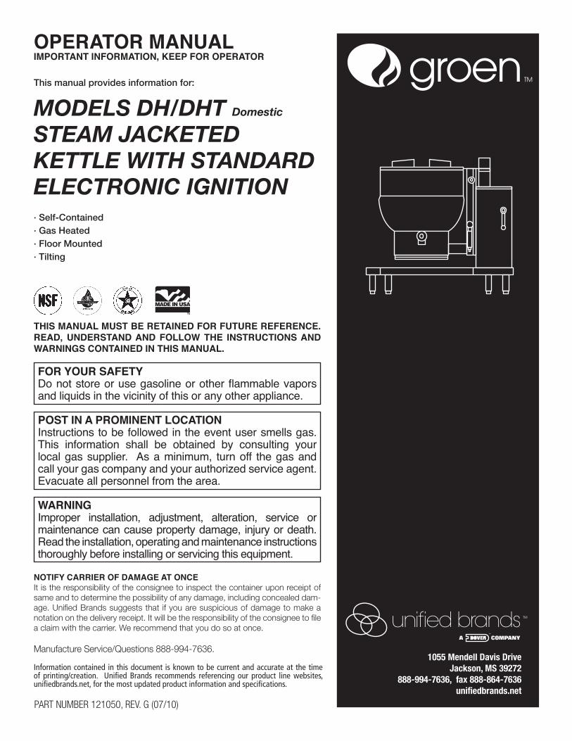
This manual provides information for:
MODELS DH/DHT Domestic
STEAM JACKETEDKETTLE WITH STANDARD ELECTRONIC IGNITION· Self-Contained· Gas Heated· Floor Mounted· Tilting
OPERATOR MANUALIMPORTANT INFORMATION, KEEP FOR OPERATOR
PART NUMBER 121050, REV. G (07/10)
.ECNEREFER ERUTUF ROF DENIATER EB TSUM LAUNAM SIHTREAD, UNDERSTAND AND FOLLOW THE INSTRUCTIONS AND WARNINGS CONTAINED IN THIS MANUAL.
FOR YOUR SAFETYDo not store or use gasoline or other flammable vapors and liquids in the vicinity of this or any other appliance.
POST IN A PROMINENT LOCATIONInstructions to be followed in the event user smells gas. This information shall be obtained by consulting your local gas supplier. As a minimum, turn off the gas and call your gas company and your authorized service agent. Evacuate all personnel from the area.
WARNINGImproper installation, adjustment, alteration, service or maintenance can cause property damage, injury or death. Read the installation, operating and maintenance instructions thoroughly before installing or servicing this equipment.
NOTIFY CARRIER OF DAMAGE AT ONCEIt is the responsibility of the consignee to inspect the container upon receipt of same and to determine the possibility of any damage, including concealed dam-age. Unified Brands suggests that if you are suspicious of damage to make a notation on the delivery receipt. It will be the responsibility of the consignee to file a claim with the carrier. We recommend that you do so at once.
Manufacture Service/Questions 888-994-7636.
Information contained in this document is known to be current and accurate at the time of printing/creation. Unified Brands recommends referencing our product line websites, unifiedbrands.net, for the most updated product information and specifications.
1055 Mendell Davis Drive Jackson, MS 39272
888-994-7636, fax 888-864-7636unifiedbrands.net
2 GROEN.COM
OM-DH
2
OM-DH
2
IMPORTANT — READ FIRST — IMPORTANT
CAUTION: BE SURE ALL OPERATORS READ, UNDERSTAND AND FOLLOW THE OPERATINGINSTRUCTIONS, CAUTIONS, AND SAFETY INSTRUCTIONS CONTAINED IN THISMANUAL.
WARNING: THIS UNIT IS INTENDED FOR USE IN THE COMMERCIAL HEATING, COOKING ANDHOLDING OF WATER AND FOOD PRODUCTS, PER THE INSTRUCTIONSCONTAINED IN THIS MANUAL. ANY OTHER USE COULD RESULT IN SERIOUSPERSONAL INJURY OR DAMAGE TO THE EQUIPMENT AND WILL VOIDWARRANTY.
WARNING: KETTLE MUST BE INSTALLED BY PERSONNEL QUALIFIED TO WORK WITHELECTRICITY AND PLUMBING. IMPROPER INSTALLATION CAN RESULT ININJURY TO PERSONNEL AND/OR DAMAGE TO EQUIPMENT.
DANGER: ELECTRICALLY GROUND THE UNIT AT THE TERMINAL PROVIDED. FAILURE TOGROUND UNIT COULD RESULT IN ELECTROCUTION AND DEATH.
WARNING: DO NOT CONNECT ANY PIPING TO THE POP SAFETY VALVE. THE VALVE MUSTBE FREE TO VENT STEAM AS NEEDED. THE ELBOW ATTACHED TO THE SAFETYVALVE SHOULD POINT TO THE FLOOR. IMPROPER INSTALLATION WILL VOIDWARRANTY.
WARNING: AVOID ALL DIRECT CONTACT WITH HOT EQUIPMENT SURFACES. DIRECT SKINCONTACT COULD RESULT IN SEVERE BURNS.
WARNING: AVOID ALL DIRECT CONTACT WITH HOT FOOD OR WATER IN THE KETTLE.DIRECT CONTACT COULD RESULT IN SEVERE BURNS.
CAUTION: DO NOT OVER FILL THE KETTLE WHEN COOKING, HOLDING OR CLEANING. KEEPLIQUIDS A MINIMUM OF 2-3” (5-8 cm) BELOW THE KETTLE BODY RIM TO ALLOWCLEARANCE FOR STIRRING, BOILING AND SAFE PRODUCT TRANSFER.
WARNING: TAKE SPECIAL CARE TO AVOID CONTACT WITH HOT KETTLE BODY OR HOTPRODUCT WHEN ADDING INGREDIENTS, STIRRING OR TRANSFERRINGPRODUCT TO ANOTHER CONTAINER.
WARNING: WHEN TILTING KETTLE FOR PRODUCT TRANSFER:
1) USE CONTAINER DEEP ENOUGH TO CONTAIN AND MINIMIZE SPLASHING.2) PLACE CONTAINER ON STABLE, FLAT SURFACE, AS CLOSE TO KETTLE AS
POSSIBLE.3) DO NOT OVER FILL CONTAINER. AVOID DIRECT SKIN CONTACT WITH HOT
CONTAINER AND ITS CONTENTS.
CAUTION: KEEP FLOORS IN FRONT OF KETTLE WORK AREA CLEAN AND DRY. IF SPILLSOCCUR, CLEAN IMMEDIATELY, TO AVOID SLIPS OR FALLS.
WARNING: FAILURE TO CHECK SAFETY VALVE OPERATION PERIODICALLY COULD RESULTIN PERSONAL INJURY AND/OR DAMAGE TO EQUIPMENT.
WARNING: WHEN TESTING SAFETY VALVE, AVOID ANY EXPOSURE TO THE STEAMBLOWING OUT OF THE SAFETY VALVE. DIRECT CONTACT WITH STEAM COULDRESULT IN SEVERE BURNS.
WARNING: TO AVOID INJURY, READ AND FOLLOW ALL PRECAUTIONS STATED ON THELABEL OF THE WATER TREATMENT COMPOUND.

OM-DH/DHT 3
OM-DH
3
OM-DH
3
WARNING: BEFORE REPLACING ANY PARTS, DISCONNECT THE UNIT FROM THE ELECTRICPOWER SUPPLY AND CLOSE THE MAIN GAS VALVE. ALLOW FIVE MINUTES FORUNBURNED GAS TO VENT.
WARNING: KEEP WATER AND SOLUTIONS OUT OF CONTROLS AND ELECTRICALEQUIPMENT. NEVER SPRAY OR HOSE THE SUPPORT HOUSING OR ELECTRICALCONNECTIONS.
CAUTION: MOST CLEANERS ARE HARMFUL TO THE SKIN, EYES, MUCOUS MEMBRANES ANDCLOTHING. PRECAUTIONS SHOULD BE TAKEN. WEAR RUBBER GLOVES, GOGGLESOR FACE SHIELD AND PROTECTIVE CLOTHING. CAREFULLY READ THE WARNINGSAND FOLLOW THE DIRECTIONS ON THE LABEL OF THE CLEANER TO BE USED.
CAUTION: USE OF ANY REPLACEMENT PARTS OTHER THAN THOSE SUPPLIED BY GROEN ORTHEIR AUTHORIZED SERVICE AGENTS CAN CAUSE OPERATOR INJURY ANDDAMAGE TO THE EQUIPMENT, AND WILL VOID ALL WARRANTIES.
IMPORTANT: SERVICE PERFORMED BY OTHER THAN FACTORY AUTHORIZED PERSONNELWILL VOID WARRANTIES.
WARNING: DO NOT HEAT AN EMPTY KETTLE. EXCESSIVE STEAM PRESSURE COULD DEVELOP.

4 GROEN.COM
Table of Contents
IMPORTANT OPERATOR WARNINGS . . . . . . . . . . . . . . . . . . . . . . . . . . . . . . . . . . . . . . . . . 2
EQUIPMENT DESCRIPTION . . . . . . . . . . . . . . . . . . . . . . . . . . . . . . . . . . . . . . . . . . . . . . . . . . 5
INSPECTION & UNPACKING . . . . . . . . . . . . . . . . . . . . . . . . . . . . . . . . . . . . . . . . . . . . . . . . . 6
INSTALLATION . . . . . . . . . . . . . . . . . . . . . . . . . . . . . . . . . . . . . . . . . . . . . . . . . . . . . . . . . . . . . 7
OPERATION . . . . . . . . . . . . . . . . . . . . . . . . . . . . . . . . . . . . . . . . . . . . . . . . . . . . . . . . . . . . . . . . 9
SEQUENCE OF OPERATION . . . . . . . . . . . . . . . . . . . . . . . . . . . . . . . . . . . . . . . . . . . . . . . . 11
MAINTENANCE . . . . . . . . . . . . . . . . . . . . . . . . . . . . . . . . . . . . . . . . . . . . . . . . . . . . . . . . . . . 12
CLEANING . . . . . . . . . . . . . . . . . . . . . . . . . . . . . . . . . . . . . . . . . . . . . . . . . . . . . . . . . . . . . . . . 15
TROUBLESHOOTING . . . . . . . . . . . . . . . . . . . . . . . . . . . . . . . . . . . . . . . . . . . . . . . . . . . . . . . 17
DIAGRAMS & SCHEMATICS . . . . . . . . . . . . . . . . . . . . . . . . . . . . . . . . . . . . . . . . . . . . . . . . 19
PARTS LISTS . . . . . . . . . . . . . . . . . . . . . . . . . . . . . . . . . . . . . . . . . . . . . . . . . . . . . . . . . . . . . . 27
SERVICE LOG . . . . . . . . . . . . . . . . . . . . . . . . . . . . . . . . . . . . . . . . . . . . . . . . . . . . . . . . . . . . . 28
REFERENCES . . . . . . . . . . . . . . . . . . . . . . . . . . . . . . . . . . . . . . . . . . . . . . . . . . . . . . . . . . . . 29
WARRANTY . . . . . . . . . . . . . . . . . . . . . . . . . . . . . . . . . . . . . . . . . . . . . . . . . . . . . . . . . . . . . . . 30
OM-DH/DHT 5
OM-DH
5
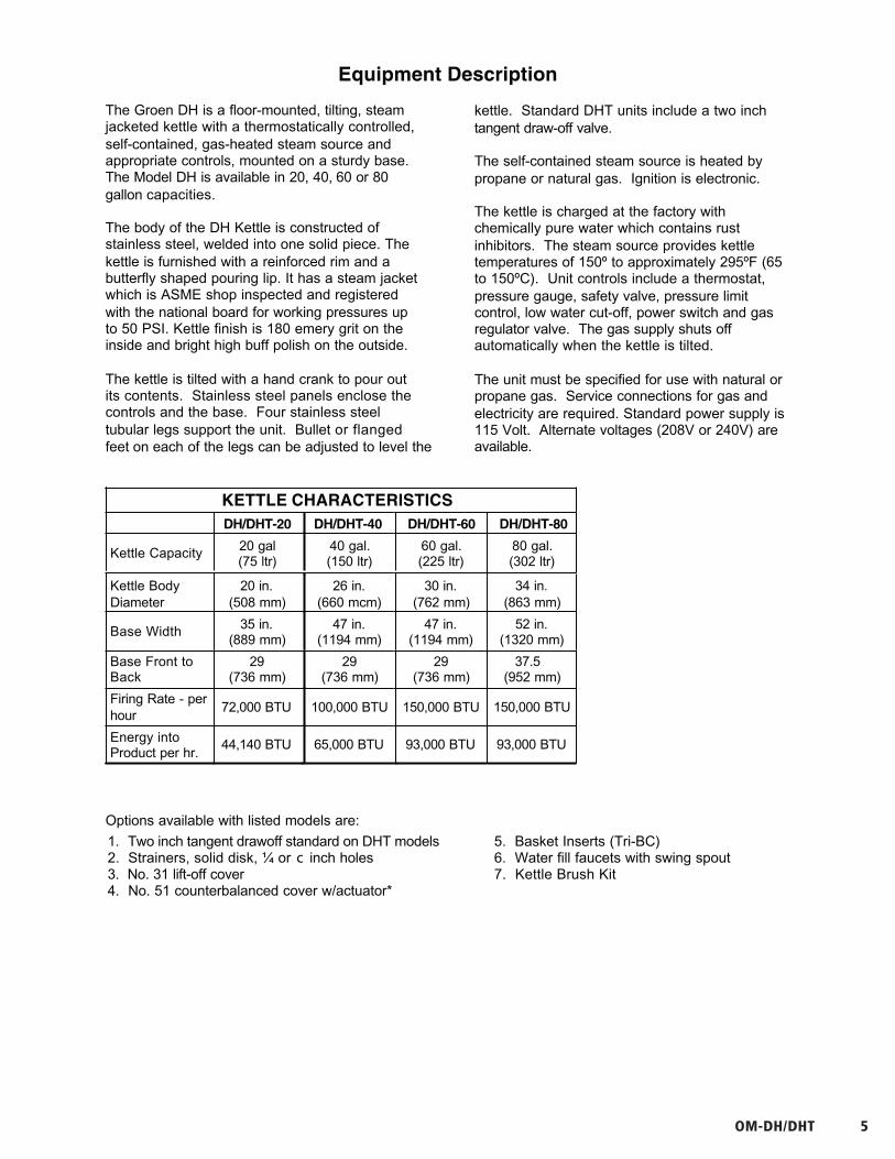
OM-DHEquipment Description
The Groen DH is a floor-mounted, tilting, steamjacketed kettle with a thermostatically controlled,self-contained, gas-heated steam source andappropriate controls, mounted on a sturdy base.The Model DH is available in 20, 40, 60 or 80gallon capacities.
The body of the DH Kettle is constructed ofstainless steel, welded into one solid piece. Thekettle is furnished with a reinforced rim and abutterfly shaped pouring lip. It has a steam jacketwhich is ASME shop inspected and registeredwith the national board for working pressures upto 50 PSI. Kettle finish is 180 emery grit on theinside and bright high buff polish on the outside.
The kettle is tilted with a hand crank to pour outits contents. Stainless steel panels enclose thecontrols and the base. Four stainless steeltubular legs support the unit. Bullet or flangedfeet on each of the legs can be adjusted to level the
kettle. Standard DHT units include a two inchtangent draw-off valve.
The self-contained steam source is heated bypropane or natural gas. Ignition is electronic.
The kettle is charged at the factory withchemically pure water which contains rustinhibitors. The steam source provides kettletemperatures of 150º to approximately 295ºF (65to 150ºC). Unit controls include a thermostat,pressure gauge, safety valve, pressure limitcontrol, low water cut-off, power switch and gasregulator valve. The gas supply shuts offautomatically when the kettle is tilted.
The unit must be specified for use with natural orpropane gas. Service connections for gas andelectricity are required. Standard power supply is115 Volt. Alternate voltages (208V or 240V) areavailable.
KETTLE CHARACTERISTICSDH/DHT-20 DH/DHT-40 DH/DHT-60
Kettle Capacity 20 gal(75 ltr)
40 gal.(150 ltr)
60 gal.(225 ltr)
Kettle BodyDiameter
20 in.(508 mm)
26 in.(660 mcm)
30 in.(762 mm)
Base Width 35 in.(889 mm)
47 in.(1194 mm)
47 in.(1194 mm)
Base Front toBack
29(736 mm)
29(736 mm)
29(736 mm)
Firing Rate - perhour
72,000 BTU 100,000 BTU 150,000 BTU
Energy intoProduct per hr.
44,140 BTU 65,000 BTU 93,000 BTU
DH/DHT-80
80 gal.(302 ltr)
34 in.(863 mm)
52 in.(1320 mm)
37.5(952 mm)
150,000 BTU
93,000 BTU
Options available with listed models are:
1. Two inch tangent drawoff standard on DHT models2. Strainers, solid disk, ¼ or c inch holes3. No. 31 lift-off cover 4. No. 51 counterbalanced cover w/actuator*
5. Basket Inserts (Tri-BC)6. Water fill faucets with swing spout7. Kettle Brush Kit

6 GROEN.COM
OM-DH
6
OM-DH
Inspection & Unpacking
The unit will arrive in a heavy shipping cartonand will be bolted or banded to a skid.Immediately upon receipt, inspect the cartoncarefully for exterior damage.
CAUTIONSHIPPING STRAPS ARE UNDER TENSIONAND CAN SNAP BACK WHEN CUT. TAKECARE TO AVOID PERSONAL INJURY ORDAMAGE TO THE UNIT BY STAPLES LEFTIN THE WALLS OF THE CARTON.
Carefully cut any polyester straps around thecarton and detach the sides of the box from theskid. Pull the carton up off the unit.
Thoroughly inspect the unit for hidden damage.Report any shipping damage or incorrectshipments to the delivery agent.
Write down the model number, serial number,and installation date, and retain this informationfor future reference. Space for these entries isprovided at the top of the Service Log at theback of this manual. Keep this manual on fileand available for operators to use.
CAUTIONTHIS UNIT WEIGHS BETWEEN 535 AND978 POUNDS (245 TO 400 Kg) DEPENDINGON SIZE. INSTALLER SHOULD USEPROPER EQUIPMENT TO LIFT SAFELY.
When installation is to begin, carefully cut anystraps which hold the unit on the skid. Lift theunit straight up off the skid. Examine packingmaterials to be sure loose parts are notdiscarded with the materials.
OM-DH/DHT 7
OM-DH
7
OM-DH
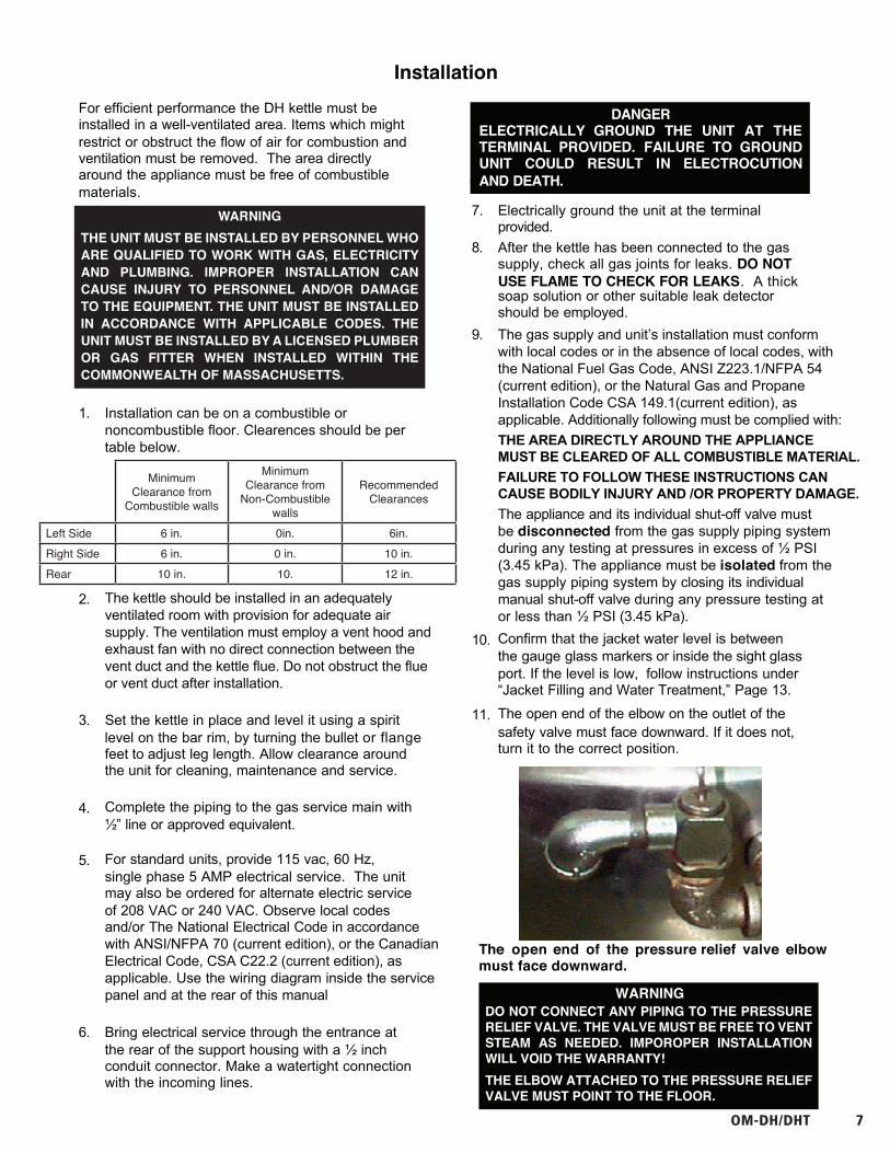
The open end of the pressure relief valve elbowmust face downward.
InstallationFor efficient performance the DH kettle must beinstalled in a well-ventilated area. Items which mightrestrict or obstruct the flow of air for combustion andventilation must be removed. The area directlyaround the appliance must be free of combustiblematerials.
1. Installation can be on a combustible ornoncombustible floor. Clearences should be pertable below.
2. The kettle should be installed in an adequatelyventilated room with provision for adequate airsupply. The ventilation must employ a vent hood andexhaust fan with no direct connection between thevent duct and the kettle flue. Do not obstruct the flueor vent duct after installation.
3. Set the kettle in place and level it using a spiritlevel on the bar rim, by turning the bullet or flangefeet to adjust leg length. Allow clearance aroundthe unit for cleaning, maintenance and service.
4. Complete the piping to the gas service main with½” line or approved equivalent.
5. For standard units, provide 115 vac, 60 Hz,single phase 5 AMP electrical service. The unitmay also be ordered for alternate electric serviceof 208 VAC or 240 VAC. Observe local codesand/or The National Electrical Code in accordancewith ANSI/NFPA 70 (current edition), or the CanadianElectrical Code, CSA C22.2 (current edition), asapplicable. Use the wiring diagram inside the servicepanel and at the rear of this manual
6. Bring electrical service through the entrance atthe rear of the support housing with a ½ inchconduit connector. Make a watertight connectionwith the incoming lines.
8.
The gas supply and unit’s installation must conformwith local codes or in the absence of local codes, withthe National Fuel Gas Code, ANSI Z223.1/NFPA 54(current edition), or the Natural Gas and PropaneInstallation Code CSA 149.1(current edition), asapplicable. Additionally following must be complied with:THE AREA DIRECTLY AROUND THE APPLIANCEMUST BE CLEARED OF ALL COMBUSTIBLE MATERIAL.FAILURE TO FOLLOW THESE INSTRUCTIONS CANCAUSE BODILY INJURY AND /OR PROPERTY DAMAGE.The appliance and its individual shut-off valve mustbe disconnected from the gas supply piping systemduring any testing at pressures in excess of ½ PSI(3.45 kPa). The appliance must be isolated from thegas supply piping system by closing its individualmanual shut-off valve during any pressure testing ator less than ½ PSI (3.45 kPa).
After the kettle has been connected to the gassupply, check all gas joints for leaks. DO NOTUSE FLAME TO CHECK FOR LEAKS. A thicksoap solution or other suitable leak detectorshould be employed.
9.
10. Confirm that the jacket water level is betweenthe gauge glass markers or inside the sight glass port. If the level is low, follow instructions under“Jacket Filling and Water Treatment,” Page 13.
11. The open end of the elbow on the outlet of thesafety valve must face downward. If it does not,turn it to the correct position.
7. Electrically ground the unit at the terminalprovided.
DANGERELECTRICALLY GROUND THE UNIT AT THETERMINAL PROVIDED. FAILURE TO GROUNDUNIT COULD RESULT IN ELECTROCUTIONAND DEATH.
WARNINGDO NOT CONNECT ANY PIPING TO THE PRESSURE RELIEF VALVE. THE VALVE MUST BE FREE TO VENT STEAM AS NEEDED. IMPOROPER INSTALLATION WILL VOID THE WARRANTY!THE ELBOW ATTACHED TO THE PRESSURE RELIEF VALVE MUST POINT TO THE FLOOR.
WARNINGTHE UNIT MUST BE INSTALLED BY PERSONNEL WHO ARE QUALIFIED TO WORK WITH GAS, ELECTRICITY AND PLUMBING. IMPROPER INSTALLATION CAN CAUSE INJURY TO PERSONNEL AND/OR DAMAGE TO THE EQUIPMENT. THE UNIT MUST BE INSTALLED IN ACCORDANCE WITH APPLICABLE CODES. THE UNIT MUST BE INSTALLED BY A LICENSED PLUMBER OR GAS FITTER WHEN INSTALLED WITHIN THE COMMONWEALTH OF MASSACHUSETTS.
Minimum Clearance from
Combustible walls
Minimum Clearance from
Non-Combustible walls
Recommended Clearances
Left Side 6 in. 0in. 6in.Right Side 6 in. 0 in. 10 in.Rear 10 in. 10. 12 in.
8 GROEN.COM
(Model DH-80E& DHT-80 only)
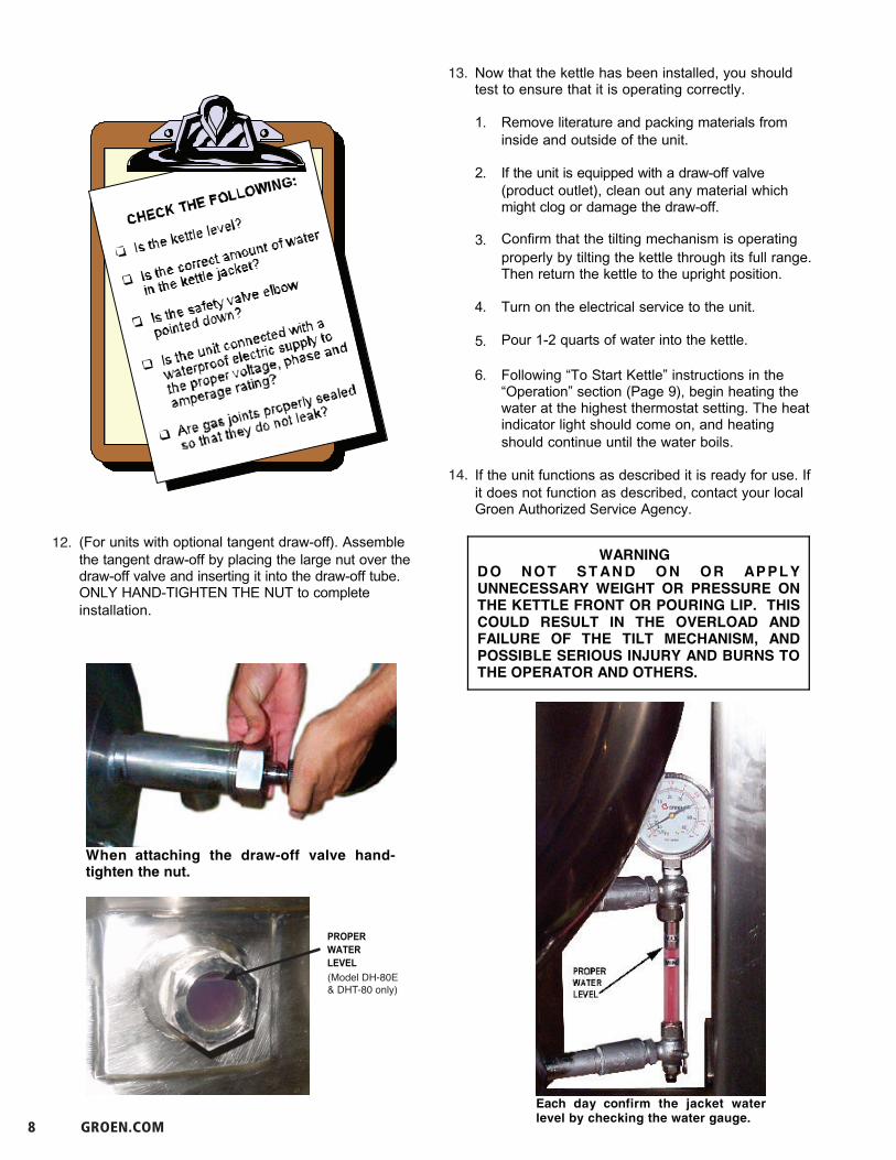
12.
13.
14.
OM-DH
8
OM-DH
8Each day confirm the jacket waterlevel by checking the water gauge.
When attaching the draw-off valve hand-tighten the nut.
(For units with optional tangent draw-off). Assemblethe tangent draw-off by placing the large nut over thedraw-off valve and inserting it into the draw-off tube. ONLY HAND-TIGHTEN THE NUT to completeinstallation.
Now that the kettle has been installed, you shouldtest to ensure that it is operating correctly.
1. Remove literature and packing materials frominside and outside of the unit.
2. If the unit is equipped with a draw-off valve(product outlet), clean out any material whichmight clog or damage the draw-off.
3. Confirm that the tilting mechanism is operatingproperly by tilting the kettle through its full range. Then return the kettle to the upright position.
4. Turn on the electrical service to the unit.
5. Pour 1-2 quarts of water into the kettle.
6. Following “To Start Kettle” instructions in the“Operation” section (Page 9), begin heating thewater at the highest thermostat setting. The heatindicator light should come on, and heatingshould continue until the water boils.
If the unit functions as described it is ready for use. Ifit does not function as described, contact your localGroen Authorized Service Agency.
PROPER WATER LEVEL
OM-DH
8
OM-DH
8Each day confirm the jacket waterlevel by checking the water gauge.
When attaching the draw-off valve hand-tighten the nut.
(For units with optional tangent draw-off). Assemblethe tangent draw-off by placing the large nut over thedraw-off valve and inserting it into the draw-off tube. ONLY HAND-TIGHTEN THE NUT to completeinstallation.
Now that the kettle has been installed, you shouldtest to ensure that it is operating correctly.
1. Remove literature and packing materials frominside and outside of the unit.
2. If the unit is equipped with a draw-off valve(product outlet), clean out any material whichmight clog or damage the draw-off.
3. Confirm that the tilting mechanism is operatingproperly by tilting the kettle through its full range. Then return the kettle to the upright position.
4. Turn on the electrical service to the unit.
5. Pour 1-2 quarts of water into the kettle.
6. Following “To Start Kettle” instructions in the“Operation” section (Page 9), begin heating thewater at the highest thermostat setting. The heatindicator light should come on, and heatingshould continue until the water boils.
If the unit functions as described it is ready for use. Ifit does not function as described, contact your localGroen Authorized Service Agency.
PROPER WATER LEVEL
OMS-DHS
8
WARNINGDO NOT CONNECT ANY PIPING TO THEPRESSURE RELIEF VALVE. THE VALVE MUSTBE FREE TO VENT STEAM AS NEEDED. IMPROPER INSTALLATION WILL VOID THEWARRANTY!THE ELBOW ATTACHED TO THE SAFETYVALVE MUST POINT TO THE FLOOR.
When attaching the draw-off valve hand-tighten thenut.
WARNINGDO NOT S T AN D O N OR APPLYUNNECESSARY WEIGHT OR PRESSURE ONTHE KETTLE FRONT OR POURING LIP. THISCOULD RESULT IN THE OVERLOAD ANDFAILURE OF THE TILT MECHANISM, ANDPOSSIBLE SERIOUS INJURY AND BURNS TOTHE OPERATOR AND OTHERS.
11. The open end of the elbow on the outlet of thepressure relief valve must face downward. If itdoes not, turn it to the correct position.
12. (For units with optional tangent draw-off).Assemble the tangent draw-off by placing thelarge nut over the draw-off valve and inserting itinto the draw-off tube. ONLY HAND-TIGHTENTHE NUT to complete installation.
Now that the kettle has been installed, you shouldtest to ensure that it is operating correctly.
1. Remove literature and packing materials frominside and outside of the unit.
2. If the unit is equipped with a draw-off valve(product outlet), clean out any material whichmight clog or damage the draw-off.
3. Confirm that the tilting mechanism is operatingproperly by tilting the kettle through its full range. Then return the kettle to the upright position.
4. Turn on the electrical service to the unit.
5. Pour 1-2 quarts of water into the kettle.
6. Following “To Start Kettle” instructions in the“Operation” section (Page 9), begin heating thewater at the highest thermostat setting. The heatindicator light should come on, and heatingshould continue until the water boils.
If the unit functions as described it is ready for use. Ifit does not function as described, contact your localGroen Certified Service Agency.
Correct Water Level
OM-DH/DHT 99
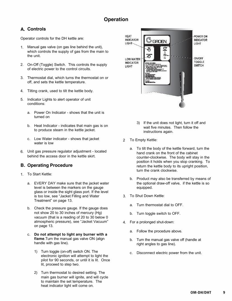
Operation
A. Controls
Operator controls for the DH kettle are:
1. Manual gas valve (on gas line behind the unit),which controls the supply of gas from the main tothe unit.
2. On-Off (Toggle) Switch. This controls the supplyof electric power to the control circuits.
3. Thermostat dial, which turns the thermostat on oroff, and sets the kettle temperature.
4. Tilting crank, used to tilt the kettle body.
5. Indicator Lights to alert operator of unitconditions:
a. Power On Indicator - shows that the unit isturned on
b. Heat Indicator - indicates that main gas is onto produce steam in the kettle jacket.
c. Low Water indicator - shows that jacketwater is low
6. Unit gas pressure regulator adjustment - locatedbehind the access door in the kettle skirt.
B. Operating Procedure
1. To Start Kettle:
a. EVERY DAY make sure that the jacket waterlevel is between the markers on the gaugeglass or inside the sight glass port. If the levelis too low, see “Jacket Filling and Water Treatment” on page 13.
b. Check the pressure gauge. If the gauge doesnot show 20 to 30 inches of mercury (Hg)vacuum (that is a reading of 20 to 30 below 0atmospheric pressure), see “Jacket Vacuum”on page 13.
c. Do not attempt to light any burner with aflame.Turn the manual gas valve ON (alignhandle with gas line).
1) Turn toggle (on-off) switch ON. Theelectronic ignition will attempt to light thepilot for 90 seconds, or until it is lit. Oncelit, proceed to step two.
2) Turn thermostat to desired setting. Themain gas burner will ignite, and will cycleto maintain the set temperature. The
3) If the unit does not light, turn it off andwait five minutes. Then follow theinstructions again.
2 To Empty Kettle:
a. To tilt the body of the kettle forward, turn thehand crank on the front of the cabinetcounter-clockwise. The body will stay in theposition it holds when you stop cranking. Toreturn the kettle body to its upright position,turn the crank clockwise.
b. Product may also be transferred by means ofthe optional draw-off valve, if the kettle is soequipped.
3. To Shut Down Kettle:
a. Turn thermostat dial to OFF.
b. Turn toggle switch to OFF.
4. For a prolonged shut-down:
a. Follow the procedure above.
b. Turn the manual gas valve off (handle atright angles to gas line).
c. Disconnect electric power from the unit.
heat indicator light will come on.
OM-DH
8
OM-DH
8Each day confirm the jacket waterlevel by checking the water gauge.
When attaching the draw-off valve hand-tighten the nut.
(For units with optional tangent draw-off). Assemblethe tangent draw-off by placing the large nut over thedraw-off valve and inserting it into the draw-off tube. ONLY HAND-TIGHTEN THE NUT to completeinstallation.
Now that the kettle has been installed, you shouldtest to ensure that it is operating correctly.
1. Remove literature and packing materials frominside and outside of the unit.
2. If the unit is equipped with a draw-off valve(product outlet), clean out any material whichmight clog or damage the draw-off.
3. Confirm that the tilting mechanism is operatingproperly by tilting the kettle through its full range. Then return the kettle to the upright position.
4. Turn on the electrical service to the unit.
5. Pour 1-2 quarts of water into the kettle.
6. Following “To Start Kettle” instructions in the“Operation” section (Page 9), begin heating thewater at the highest thermostat setting. The heatindicator light should come on, and heatingshould continue until the water boils.
If the unit functions as described it is ready for use. Ifit does not function as described, contact your localGroen Authorized Service Agency.
PROPER WATER LEVEL

10 GROEN.COM
OM-DH
10
OM-DH
10
WARNINGWHEN TILTING KETTLE:1) WEAR PROTECTIVE OVEN MITT AND
PROTECTIVE APRON.2) USE DEEP CONTAINER TO CONTAIN
AND MINIMIZE PRODUCT SPLASHING.3) PLACE CONTAINER ON STABLE,
FLAT SURFACE, AS CLOSE TOKETTLE AS POSSIBLE.
4) STAND TO RIGHT OF KETTLE WHILEPOURING — NOT DIRECTLY IN POURPATH OF HOT CONTENTS.
5) POUR SLOWLY, M A I N T A I N I N GCONTROL OF KETTLE, AND RETURNKETTLE BODY TO UPRIGHT POSITIONAFTER CONTAINER IS FILLED ORTRANSFER IS COMPLETE.
6) DO NOT OVERFILL CONTAINER.AVOID SKIN CONTACT WITH HOTCONTAINER AND ITS CONTENTS.
5. If power fails:
a. Do not attempt to operate the unit untilelectric power is restored.
b. When power comes back on, followdirections “To Start Kettle,” above.
C. Use of Common Accessories
1. Lift-Off or Counterbalanced Cover
As with stock pot cooking, an optional cover canspeed up the heating of water and food products.It helps retain heat and reduces the heat andhumidity in the kitchen. A cover can reducesome product cook times and help maintain thetemperature, color and texture of products heldor simmered for longer periods.
Be sure the handle is secure on the lift-off coverbefore using. ALWAYS use the handle to placeor remove cover from the kettle. Wear protectiveoven mitts and apron
When putting a lift-off cover on the kettle,position it on top of kettle rim, with its flat edgefacing the pouring lip.
WARNINGAVOID ALL DIRECT CONTACT WITH HOTSURFACES AND HOT FOOD OR WATERIN THE KETTLE. DIRECT CONTACTCOULD RESULT IN SEVERE BURNS.
When removing a lift-off cover:
a. Firmly grasp the handle, and lift the rearedge (farthest from operator) 1-2” (3-5 cm)to allow steam and water vapor to escape.Wait 2-3 seconds.
b. Tilt cover to 45-60° angle to allow any hotcondensate or product to roll off cover backinto kettle.
c. Remove cover, ensuring that remaining hotcondensate or product does not drip onoperator, floor or work surfaces.
d. Place cover on safe, flat, sanitary, out-of-the-way surface, or return to kettle.
CAUTIONDO NOT TILT KETTLE WITH LIFT-OFFCOVER IN PLACE. COVER MAY SLIDEOFF, CAUSING INJURY TO OPERATOR.
2. Basket Insert
An optional kettle basket insert set (Tri-BC) willassist in cooking water-boiled products includingeggs, potatoes, vegetables, shell fish, pasta andrice. The nylon mesh liner must be used forproducts smaller than the basket mesh size,(approx. ¼” (6 mm). This includes rice and smallpasta shapes.
a. Allow for displacement of the three basketsand product. This may mean only half fillingthe kettle. Test baskets and productdisplacement with the kettle OFF, and withcold water in the kettle.
CAUTIONDO NOT OVERFILL THE KETTLE WHENCOOKING, HOLDING OR CLEANING.KEEP LIQUIDS AT LEAST 2-3” (5-8 cm)BELOW THE KETTLE RIM TO ALLOWCLEARANCE FOR STIRRING, BOILINGAND SAFE PRODUCT TRANSFER.

OM-DH/DHT 11
OM-DH
11
OM-DH
11
WARNINGAVOID ALL DIRECT CONTACT WITH HOTFOOD OR WATER IN THE KETTLE. DIRECTCONTACT COULD RESULT IN SEVEREBURNS.
b. Load baskets on a level, stable worksurface.
c. Lift loaded baskets with both hands. Gethelp from another person if the basket is tooheavy for safe handling.
d. Slowly lower product into kettle and securelyhook basket to the “Y” frame.
e. When removing baskets with cookedproduct, lift straight up, ensuring basketbottoms clear the kettle rim and pouring lip.Wear protective oven mitts and protectiveapron.
f. Allow hot water to fully drain from product,before moving basket away from the kettle.Do not rest baskets on kettle rim or pouringlip. If baskets are too heavy for individual tolift and safely move, get help. Removeproduct immediately from basket intoanother container, being sure to avoidcontact with hot product and hot basket or...
g. Place baskets with food on a stable, flatsurface, inside a solid steamer or bake pan,to catch any remaining hot water drainingfrom product.
Sequence of OperationThe following “action-reaction” outline is provided tohelp understand how the DH kettle works.
1. When the power switch is turned on, it starts thespark igniter and opens the automatic valve forthe pilot burner. The spark ignites a pilot flame,which heats the sensor. The sensor then sendsa signal to turn off the spark. The flamethereafter acts as a standing pilot until the poweris turned off.
2. If the pilot flame is not sensed within 90 secondsafter spark begins, a timer shuts down the entireoperation. To attempt a second trial for ignition,turn off the power switch. Check the gas supplyvalves and wait five minutes before trying againby switching power on. If you cannot establish apilot flame in four tries, close all valves, turn offthe power, and contact an authorized GroenService Agency.
3. When the operator sets a temperature on thethermostat, it causes the automatic valve to
admit gas to the main burner, where it is ignitedby the pilot flame. When the kettle reaches theset temperature, the thermostat switch opens. This stops the signal to the gas control valve andshuts off gas to the main burner. The pilot flameremains lit. When the kettle cools below the settemperature, the thermostat switch closes andstarts another cycle. On and off cyclingcontinues and maintains the kettle at the desiredtemperature. This action is indicated by the Heatindicator light.
The kettle has the following safety features inaddition to the 90-second ignition timer:
1. Low water cutoff relay that will shut off gassupplies to all burners until the jacket water levelis corrected.
2. High limit pressure switch, set to open at about46 PSI and to shut down the burners until jacketpressure is decreased.
3. Pop safety valve, which will release steam ifjacket pressure exceeds 50 PSI.
4. Tilt switch, which shuts off all burners when thekettle is tilted.
5. Gas pressure regulator built into the gas controlvalve.
12 GROEN.COM
OM-DH
12
OM-DH
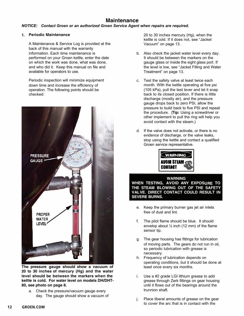
The pressure gauge should show a vacuum of20 to 30 inches of mercury (Hg) and the waterlevel should be between the markers when thekettle is cold. For water level on models DH/DHT-80, see photo on page 8.
MaintenanceNOTICE: Contact Groen or an authorized Groen Service Agent when repairs are required.
1. Periodic Maintenance
A Maintenance & Service Log is provided at theback of this manual with the warrantyinformation. Each time maintenance isperformed on your Groen kettle, enter the dateon which the work was done, what was done,and who did it. Keep this manual on file andavailable for operators to use.
Periodic inspection will minimize equipmentdown time and increase the efficiency ofoperation. The following points should bechecked:
a. Check the pressure/vacuum gauge everyday. The gauge should show a vacuum of
20 to 30 inches mercury (Hg), when thekettle is cold. If it does not, see “JacketVacuum” on page 13.
b. Also check the jacket water level every day. It should be between the markers on thegauge glass or inside the sight glass port. Ifthe level is low, see “Jacket Filling and Water Treatment” on page 13.
c. Test the safety valve at least twice eachmonth. With the kettle operating at five psi(105 kPa), pull the test lever and let it snapback to its closed position. If there is littledischarge (mostly air), and the pressuregauge drops back to zero PSI, allow thepressure to build back to five PSI and repeatthe procedure. (Tip: Using a screwdriver orother implement to pull the ring will help youavoid contact with the steam.)
d. If the valve does not activate, or there is noevidence of discharge, or the valve leaks,stop using the kettle and contact a qualifiedGroen service representative.
WARNINGWHEN TESTING, AVOID ANY EXPOSURE TOTHE STEAM BLOWING OUT OF THE SAFETYVALVE. DIRECT CONTACT COULD RESULT INSEVERE BURNS.
e. Keep the primary burner gas jet air inletsfree of dust and lint.
f. The pilot flame should be blue. It shouldenvelop about ½ inch (12 mm) of the flamesensor tip.
g. The gear housing has fittings for lubricationof moving parts. The gears do not run in oil,so periodic lubrication with grease isnecessary.
h. Frequency of lubrication depends onoperating conditions, but it should be done atleast once every six months.
i. Use a #2 grade LGI lithium grease to addgrease through Zerk fittings on gear housinguntil it flows out of the bearings around thetrunnion shaft.
j. Place liberal amounts of grease on the gearto cover the arc that is in contact with the

OM-DH/DHT 13
OM-DH
13
OM-DH
Test the safety valve at least twice monthly.Liberally grease the wheel where it contacts theworm gear.
Add grease through Zerk Fittings.
worm gear.
k. Keep electrical wiring and connections ingood condition.
l. Keep the inside of the control console cleanand dry.
m. Keep burner slots clean.
2. Jacket Vacuum/Removing Air from Jacket
When the kettle is cold, a positive pressurereading on the pressure/vacuum gauge or areading near zero indicates that there is air in thejacket. Air in the jacket acts as an insulator, andslows kettle heating.
To remove air:
a. Start the unit. (Be sure there is water orproduct in the kettle when heating).
b. When the pressure/vacuum gauge reachesa positive pressure reading of five PSI,release the trapped air and steam by pullingup the safety valve ring for about fiveseconds. Repeat this step three or fourtimes. Then let the pull ring snap back intothe closed position.
c. If there is little discharge (mostly air), and thepressure gauge drops back to zero PSI,allow the pressure to build back to five PSIand repeat the procedure.
d. Once steam has been vented from the jacketas described in b, above, remove the hotwater from the kettle and replace it with cold. This will condense steam in the kettle jacket,and the pressure gauge should show areading of 20 to 30 inches mercury (Hg)below zero. If it does not, or if the vacuum isleaking down, contact a Groen authorizedservice agency to correct the problem.
3. Jacket Filling and Water Treatment
The jacket was charged at the factory with theproper amount of treated water. You may needto restore this water, either because it was lostas venting steam or by draining. If you arereplacing water lost as steam, use distilled water.If you are replacing treated water that ran out ofthe jacket, prepare more treated water asdirected in “Water Treatment Procedure,” below.
Allow the kettle to cool completely. Theprocedure will be easier with the kettle undervacuum ( pressure gauge reading below zero).
(ONLY ONDH-60 ANDSMALLER)
14 GROEN.COM
OM-DH
14
OM-DHa. Make sure the fill valve is closed, and
remove the square head pipe plug withopen-ended wrench.
b. Position a funnel in the opening and fill itwith properly treated water.
c. Slowly open the fill valve to allow water to besucked into the jacket. Quickly close thevalve to prevent air from entering.
d. Check water level in the jacket to ensure thatit is between minimum and maximum markson glass or at the top of the sight glass port formodels DH/DHT-80 (see photo on page 8).
e. Close the valve and reinstall the square-head pipe plug.
f. Reestablish the jacket vacuum as describedin Paragraph 2, above, if the pressure gaugedoes not show a negative reading of 20 to30 inches mercury (Hg).
4. Water Treatment Procedure
a. Obtain water treatment compound and a pHtest kit from your Groen Service Agent.
WARNINGTO AVOID INJURY, READ AND FOLLOW ALLPRECAUTIONS ON THE LABEL OF THEWATER TREATMENT COMPOUND.
b. Fill a mixing container with the measuredamount of water required. (See table).Distilled water is recommended.
Kettle Model RecommendedJacket Fill
DH-20, DHT-20 2½ Gallons
DH/1-40, DHT/1-40 3½ Gallons
DH-60, DHT-60 4 Gallons
DH-80, DHT-80 1 1/4 Gallons*
c. Hang a strip of pH test paper on the rim ofthe container, with about 1 inch of the stripbelow the surface of the water.
d. Measure the water treatment compound. One way to do this is to add the compoundfrom a measuring cup.
e. Stir the water continuously, while you slowlyadd treatment compound, until the water hasa pH between 10.5 and 11.5. Judge the pHby frequently comparing the test strip colorwith the color chart provided in the test kit.
f. As you add water to the jacket, check waterlevel to ensure that it is between minimumand maximum marks on glass or at the top ofthe sight glass port for models DH/DHT-80 (seephoto on page 8). Stop adding water when itreaches the maximum marker on the gauge.
g. Record the exact amounts of water andtreatment compound needed. Theseamounts may be used again, if the samewater sources and compound are used.However, it is best to check the pH eachtime treated water is prepared.
5. Component Replacement
WARNINGBEFORE REPLACING ANY PARTS,DISCONNECT THE UNIT FROM THE ELECTRICPOWER SUPPLY AND CLOSE THE MAIN GASVALVE. ALLOW FIVE MINUTES FORUNBURNED GAS TO VENT.
When component replacement involves breaking agas pipe connection, check the new connection withsoap solution or an appropriate leak detector. DONOT USE A FLAME TO TEST FOR LEAKS.
Internal wiring is marked as shown on the circuitschematic drawings (inside control housing and inthis manual). Be sure that new components arewired in the same manner as old components. Anexamination of the circuit schematic shows that thesafety components are wired in series. In mostcases, a faulty component may be isolated with ajumper wire to verify that the component is faulty. Ifthis determination is made, contact a AuthorizedGroen Service Agency for assistance.
* this number is not a mistake
OM-DH/DHT 15
OM-DH
15
OM-DH
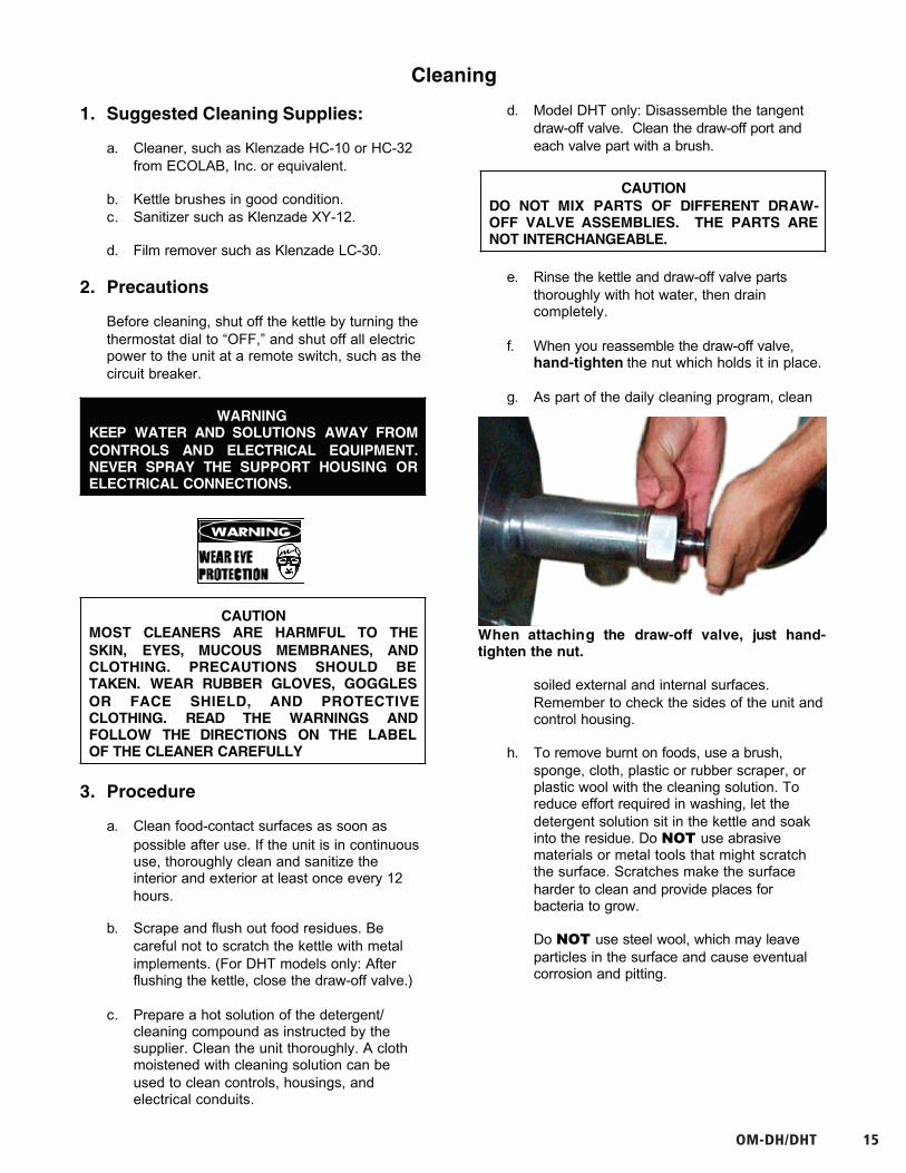
When attaching the draw-off valve, just hand-tighten the nut.
Cleaning
1. Suggested Cleaning Supplies:
a. Cleaner, such as Klenzade HC-10 or HC-32from ECOLAB, Inc. or equivalent.
b. Kettle brushes in good condition.c. Sanitizer such as Klenzade XY-12.
d. Film remover such as Klenzade LC-30.
2. Precautions
Before cleaning, shut off the kettle by turning thethermostat dial to “OFF,” and shut off all electricpower to the unit at a remote switch, such as thecircuit breaker.
WARNINGKEEP WATER AND SOLUTIONS AWAY FROMCONTROLS AND ELECTRICAL EQUIPMENT.NEVER SPRAY THE SUPPORT HOUSING ORELECTRICAL CONNECTIONS.
CAUTIONMOST CLEANERS ARE HARMFUL TO THESKIN, EYES, MUCOUS MEMBRANES, ANDCLOTHING. PRECAUTIONS SHOULD BETAKEN. WEAR RUBBER GLOVES, GOGGLESOR FACE SHIELD, AND PROTECTIVECLOTHING. READ THE WARNINGS ANDFOLLOW THE DIRECTIONS ON THE LABELOF THE CLEANER CAREFULLY
3. Procedure
a. Clean food-contact surfaces as soon aspossible after use. If the unit is in continuoususe, thoroughly clean and sanitize theinterior and exterior at least once every 12hours.
b. Scrape and flush out food residues. Becareful not to scratch the kettle with metalimplements. (For DHT models only: Afterflushing the kettle, close the draw-off valve.)
c. Prepare a hot solution of the detergent/cleaning compound as instructed by thesupplier. Clean the unit thoroughly. A clothmoistened with cleaning solution can beused to clean controls, housings, andelectrical conduits.
d. Model DHT only: Disassemble the tangentdraw-off valve. Clean the draw-off port andeach valve part with a brush.
CAUTIONDO NOT MIX PARTS OF DIFFERENT DRAW-OFF VALVE ASSEMBLIES. THE PARTS ARENOT INTERCHANGEABLE.
e. Rinse the kettle and draw-off valve partsthoroughly with hot water, then draincompletely.
f. When you reassemble the draw-off valve,hand-tighten the nut which holds it in place.
g. As part of the daily cleaning program, clean
soiled external and internal surfaces.Remember to check the sides of the unit andcontrol housing.
h. To remove burnt on foods, use a brush,sponge, cloth, plastic or rubber scraper, orplastic wool with the cleaning solution. Toreduce effort required in washing, let thedetergent solution sit in the kettle and soakinto the residue. Do NOT use abrasivematerials or metal tools that might scratchthe surface. Scratches make the surfaceharder to clean and provide places forbacteria to grow.
Do NOT use steel wool, which may leaveparticles in the surface and cause eventualcorrosion and pitting.

16 GROEN.COM
OM-DH
16
OM-DHi. The outside of the unit may be polished with
a stainless steel cleaner such as “Zepper”from Zep Manufacturing Co. or equivalent.
j. When equipment needs to be sanitized, usea solution equivalent to one that supplies200 parts per million available chlorine.Obtain advice on sanitizing agents from yoursupplier of sanitizing products.
k. Following the supplier’s instructions, applythe agent after the unit has been cleanedand drained. Rinse off the sanitizerthoroughly.
NOTICENEVER LEAVE A CHLORINE SANITIZER INCONTACT WITH STAINLESS STEELSURFACES LONGER THAN 30 MINUTES.LONGER CONTACT CAN CAUSESTAINING AND CORROSION.
k. It is recommended that each piece ofequipment be sanitized just before use.
l. If there is difficulty removing mineraldeposits or a film left by hard water or foodresidues, clean the kettle thoroughly andthen use a deliming agent, like GroenDelimer/Descaler (Part Number 114800) orLime-Away from Ecolab, in accordance withthe manufacturer’s directions. Rinse anddrain the unit before further use.
m. If cleaning problems persist, contact yourcleaning product representative forassistance. The supplier has a trainedtechnical staff with laboratory facilities toserve you.

OM-DH/DHT 17
OM-DH
17
OM-DH
17
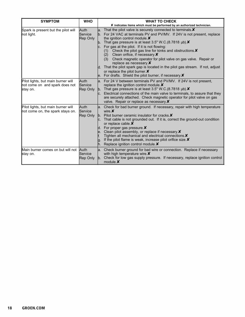
TroubleshootingYour Groen kettle is designed to operate smoothly and efficiently if properly maintained. However, the following isa list of checks to make in the event of a problem. Wiring diagrams are furnished inside the service panel and inthis manual. If an item on the list is followed by , the work should be done by a qualified servicerepresentative.
WARNINGBEFORE REPLACING ANY PARTS, DISCONNECT THE UNIT FROM THE ELECTRIC POWER SUPPLYAND CLOSE THE MAIN GAS VALVE. ALLOW FIVE MINUTES FOR UNBURNED GAS TO VENT.
CAUTIONUSEING REPLACEMENT PARTS OTHER THAN THOSE SUPPLIED BY GROEN OR THEIR AUTHORIZEDDISTRIBUTOR CAN CAUSE OPERATOR INJURY AND EQUIPMENT DAMAGE AND WILL VOID ALLWARRANTIES.
SYMPTOM WHO WHAT TO CHECK indicates items which must be performed by an authorized technician.
Kettle is hard to tilt. User a. Gears for foreign materials, and lubrication.
AuthServiceRep Only
b. Gears for alignment. c. Worm gears or broken gears.
Kettle continues heating after itreaches desired temperature.
User a. Thermostat dial setting.
AuthServiceRep Only
b. Thermostat calibration.
c. Thermostat operation. The thermostat should click when the dial isrotated to settings above and below the temperature of the kettle.
Kettle stops heating before itreaches the desired temperature.
User a. Thermostat dial setting.
AuthServiceRep Only
b. Thermostat calibration.c. Thermostat operation. The thermostat should click when the dial is
rotated to settings above and below the temperature of the kettle.Safety Valve pops open User a. For air in the jacket. See “Jacket Vacuum” in the Maintenance section.
b. Thermostat dial setting.
AuthServiceRep Only
c. For defective thermostat. The thermostat should click when the dial isrotated to settings above and below the temperature of the kettle. Ifdefective, replace.
d. For defective safety valve. If the valve pops at pressures below 49 PSI,replace.
Burners will not light. User a. That the main gas supply valve is open. (handle is in line with gas pipe).b. Gas supply to the building.c. That the kettle body is not tilted.
AuthServiceRep Only
d. Thermostat operation. The thermostat should click when the dial isrotated to settings above and below the temperature of the kettle.
f. That tilt limit switch is closed when body is not tilted.
System does not produce a spark AuthServiceRep Only
a. Thermostat, and close the contacts if they are open b. AC voltage between terminals on secondary side of transformer. If it is
not 24 Volt, replace the transformer c. That the high tension cable is firmly attached and in good condition. If
cracked or brittle, replace.d. Pilot electric ceramic for crack or break.e. Pilot spark gap. Regap.
18 GROEN.COM
OM-DH
18
OM-DHSYMPTOM WHO WHAT TO CHECK
indicates items which must be performed by an authorized technician.
18
Spark is present but the pilot willnot light.
AuthServiceRep Only
a. That the pilot valve is securely connected to terminals.b. For 24 VAC at terminals PV and PV/MV. If 24V is not present, replace
the ignition control module.b. That gas pressure is at least 3.5" W.C.(8.7818 b).c. For gas at the pilot. If it is not flowing:
(1) Check the pilot gas line for kinks and obstructions.(2) Clean orifice, if necessary.(3) Check magnetic operator for pilot valve on gas valve. Repair or
replace as necessary.d. That the pilot spark gap is located in the pilot gas stream. If not, adjust
or replace the pilot burner.e. For drafts. Shield the pilot burner, if necessary.
Pilot lights, but main burner willnot come on and spark does notstay on.
AuthServiceRep Only
a. For 24 V between terminals PV and PV/MV. If 24V is not present,replace the ignition control module.
b. That gas pressure is at least 3.5" W.C.(8.7818 b).c. Electrical connections of the main valve to terminals, to assure that they
are securely attached. Check magnetic operator for pilot valve on gasvalve. Repair or replace as necessary.
Pilot lights, but main burner willnot come on, the spark stays on.
AuthServiceRep Only
a. Check for bad burner ground. If necessary, repair with high temperaturewire.
b. Pilot burner ceramic insulator for cracks.c. That cable is not grounded out. If it is, correct the ground-out condition
or replace cable.d. For proper gas pressure.e. Clean pilot assembly, or replace if necessary.f. Tighten all mechanical and electrical connections.g. If the pilot flame is weak, increase pilot orifice size.h. Replace ignition control module.
Main burner comes on but will notstay on.
AuthServiceRep Only
a. Check burner ground for bad wire or connection. Replace if necessarywith high temperature wire.
b. Check for low gas supply pressure. If necessary, replace ignition controlmodule.

OM-DH/DHT 19
OM-DH
22
OM
-DH
Sta
nd
an
d H
ou
sin
g A
ssem
bly
Par
ts L
ist
for
DH
/DH
T-6
0 o
r S
mal
ler
Siz
es
Key
Des
crip
tio
nP
art
No
.K
eyD
escr
ipti
on
Par
t N
o.
Key
Des
crip
tio
nP
art
No
.A
Sta
nd
an
d H
ou
sin
g A
ssem
bly
1238
135
Hou
sing
Cla
ddin
g, D
H-2
012
3810
91/
2" L
ock
Was
her
0057
35
1C
abin
et S
ide
Pan
el04
7882
5H
ousi
ng C
ladd
ing,
DH
-40
and
6012
3811
10S
crew
Tru
ss #
8-32
x 3
/800
5764
2S
tand
Cla
ddin
gM
S96
694
6T
ray
Line
r00
1475
11S
crew
Tru
ss #
8-32
x 1
-1/4
Lg.
0712
47
3B
ase
Ass
em
bly
MS
9669
87
Nut
Hex
agon
1/2
-13
Hea
vy D
uty
0057
0512
Cab
inet
Cov
er00
1465
4H
ousi
ng W
eldm
ent
Ass
embl
yM
S47
332
8S
crew
Hex
Hea
d C
ap 1
/2-1
3 x1
-1/2
0086
79

20 GROEN.COM
Part
s Li
st fo
r DH
/DH
T-80
1314
9273
1208
1698
1100
5764
1000
5705
900
8679
800
5735
700
5049
615
0252
514
9241
415
0253
314
9242
214
9775
114
9257
KEY
PART
NO.
DESC
RIPT
ION
6
11 5
2
3
413
12
910
87
1
CABI
NET,
SIDE
PANE
L
SCRE
W 8
-32
X 1-
3/8"
LONG
, TRU
SS H
EAD
SCRE
W 8
-32
X 3/
8" LO
NG, T
RUSS
HEA
D
NUT H
EXAG
ON 1
/2"-1
3
SCRE
W H
EX H
EAD
CAP
1/2-
13 X
1-1
/2 LO
NG
WAS
HER
LOCK
1/2
"
WAS
HER,
PLAI
N 1/
2"
COVE
R, TO
P PE
DEST
AL C
LADD
ING
CLAD
DING
, PED
ESTA
L ASS
EMBL
Y
TRAY
, LIN
ER
WEL
DMEN
T, PE
DEST
AL
WEL
DMEN
T, ST
AND
CLAD
DING
FRAM
E ASS
EMBL
Y DH
/DHT
-80
Sta
nd
& H
ou
sin
g A
sse
mb
lyK
eyD
esc
rip
tio
nP
art
No
.
AS
tan
d &
Ho
usi
ng
Ass
em
bly
1FR
AM
E A
SSEM
BLY
DH
/DH
T-80
1492
57
2W
ELD
MEN
T, S
TAN
D C
LAD
DIN
G14
9775
3W
ELD
MEN
T, P
EDES
TAL
1492
42
4TR
AY,
LIN
ER15
0253
5C
LAD
DIN
G, P
RED
ESTA
L A
SSEM
BLY
1492
41
6C
OV
ER, T
OP
PED
ESTA
L C
LAD
DIN
G15
0252
7W
ASH
ER, P
LAIN
1/2
”00
5049
8W
ASH
ER L
OC
K 1
/2”
0057
35
9SC
REW
HEX
HEA
D C
AP
1/2
-13
X 1
-1/2
LO
NG
0086
79
10N
UT
HEX
AG
ON
1/2
”-13
0057
05
11SC
REW
8-3
2 X
3/8
” LO
NG
, TR
USS
HEA
D00
5764
12SC
REW
8-3
2 X
1-3
/8” L
ON
G, T
RU
SS H
EAD
0816
98
13C
AB
INET
, SID
E PA
NEL
1492
73
OM-DH/DHT 21
OM-DH
23
OM
-DH
23
Gas
Val
ve P
ipin
g a
nd
Bo
tto
m C
om
po
nen
ts A
ssem
bly
Par
ts L
ist
for
DH
/DH
T-6
0 o
r S
mal
ler
Siz
es
To
orde
r pa
rts,
con
tact
you
r G
roen
Cer
tifie
d S
ervi
ce A
genc
y.
Sup
ply
the
mod
el d
esig
natio
n, p
art
desc
riptio
n, p
art
num
ber,
qua
ntity
, an
d, w
here
app
licab
le,
volta
gean
d ph
ase.
Key
Des
crip
tio
nP
art
No
.K
eyD
escr
ipti
on
Par
t N
o.
Key
Des
crip
tio
nP
art
No
.
BG
as V
alve
Pip
ing
&B
ott
om
Co
mp
s.12
7369
9P
ress
ure
Sw
itch
1/4"
0969
632
0C
over
, Bot
tom
04
98
01
1T
ube,
Cop
per,
1/2
"00
7334
10C
onne
ctor
1/2
NP
T M
ale
0490
93
2E
lbow
, F
emal
e, 9
0 D
eg.
1/2
NP
T05
5634
11G
as V
alve
1238
15
3T
herm
osta
t, el
ectr
ic00
9730
12B
rack
et S
uppo
rt06
5382
21C
ap B
otto
m C
over
Pla
te04
9003
4E
lbow
, 90
Deg
1/2
NP
T00
8747
13S
crew
, P
an H
ead
#8-3
2 x
3/8"
0057
6422
Ga
ske
t, B
ott
om
Pla
te00
7937
5N
ippl
e, 1
/2 N
PT
x 2
-1/2
" Lo
ng00
5552
14N
ut,
Hex
agon
Kep
1/4
01
2940
23S
crew
, 10
-32x
3/8,
Hex
0697
73
6E
lect
rode
, W
ater
Lev
el00
2170
16B
ar00
5440
24E
lbow
, 1/
8" N
PT
Mal
e x
1/4"
Tub
e09
7195
7T
ee,
1/2
x 1/
2 T
ube
x 3/
8 M
PT
0745
9317
Cla
mp,
Rig
id C
ondu
it06
8687
25T
ube,
Alu
min
um 1
/4"
OD
x 3
2"00
6796
8C
onne
ctor
1/4
" N
PT
Fem
ale
0970
741
9B
oo
t Pro
be
10
11
43
22 GROEN.COM
Part
s Li
st fo
r DH
/DH
T-80
Key
Des
crip
tio
nP
art
No.
BG
as V
alve
, Pip
ing
& B
ott
om
Co
mp
on
ents
1
TUB
E, P
ILO
T15
0949
2FI
TTIN
G C
OM
PRES
SIO
N05
7217
3TU
BE,
VA
LVE
OU
TLET
. DH
/DH
T-80
1497
65
4EL
ECTR
OD
E W
ATER
LEV
EL07
6526
5B
RA
CK
ET S
UPP
OR
T06
5382
6SC
REW
PA
N H
EAD
#8-
32 X
3/8
”00
5764
7N
UT,
HEX
AG
ON
KEE
PS 1
/401
2940
8B
AR
0054
40
9C
LAM
P, RI
GID
CO
ND
UIT
0686
87
10SW
ITC
H P
RESS
URE
1/4
NPT
0969
63
11FI
TTIN
G C
OM
PRES
SIO
N04
9093
ITEM
NO.
11 13122 4 531
1718
1615
14
212019
67
89
10
115
0949
TUB
E, P
ILO
T2
0572
17FI
TTIN
G C
OM
PRES
SIO
N3
1497
65TU
BE,
VA
LVE
OU
TLET
. DH
/DH
T-80
407
6526
ELEC
TRO
DE
WAT
ER L
EVEL
506
5382
BRA
CK
ET S
UPP
OR
T6
0057
64
SCRE
W P
AN
HEA
D #
8-32
X 3
/8"
701
2940
NU
T, H
EXA
GO
N K
EEPS
1/4
800
5440
BAR
906
8687
CLA
MP,
RIG
ID C
ON
DU
IT10
0969
63SW
ITC
H P
RESS
URE
1/4
NPT
1104
9093
FITT
ING
CO
MPR
ESSI
ON
1200
4584
FITT
ING
CO
MPR
ESSI
ON
90
1312
3815
VALV
E, G
AS
JOH
NSO
N C
ON
TRO
LS14
1497
66TU
BE
3/8"
X 3
", C
OO
PER
1514
9767
TUB
E, V
ALV
E IN
LET.
DH
/DH
T-80
1600
9730
THER
MO
STAT
, ELE
CTR
IC17
0087
47EL
BO
W 9
0 D
EG 1
/2"
NPT
1806
9773
SCRE
W, #
10-3
2 X
3/8
, HEX
.19
0498
03C
AP
BO
TTO
M C
OV
ER P
LATE
2000
7937
GA
SKET
, BO
TTO
M P
LATE
2114
9774
CO
VER
, BO
TTO
M
PART
NO.
DESC
RIPT
ION
Key
Des
crip
tio
nP
art
No.
12FI
TTIN
G C
OM
PRES
SIO
N 9
000
4584
13VA
LVE,
GA
S JO
HN
SON
CO
NTR
OLS
1238
15
14TU
BE
3/8”
X 3
”, CO
OPE
R14
9766
15TU
BE,
VA
LVE
INLE
T. D
H/D
HT-
8014
9767
16TH
ERM
OST
AT, E
LEC
TRIC
0097
30
17EL
BO
W 9
0 D
EG 1
/2” N
PT00
8747
18SC
REW
, #10
-32
X 3
/8, H
EX.
0697
73
19C
AP
BO
TTO
M C
OV
ER P
LATE
0498
03
20G
ASK
ET, B
OTT
OM
PLA
TE00
7937
21C
OV
ER, B
OTT
OM
1497
74
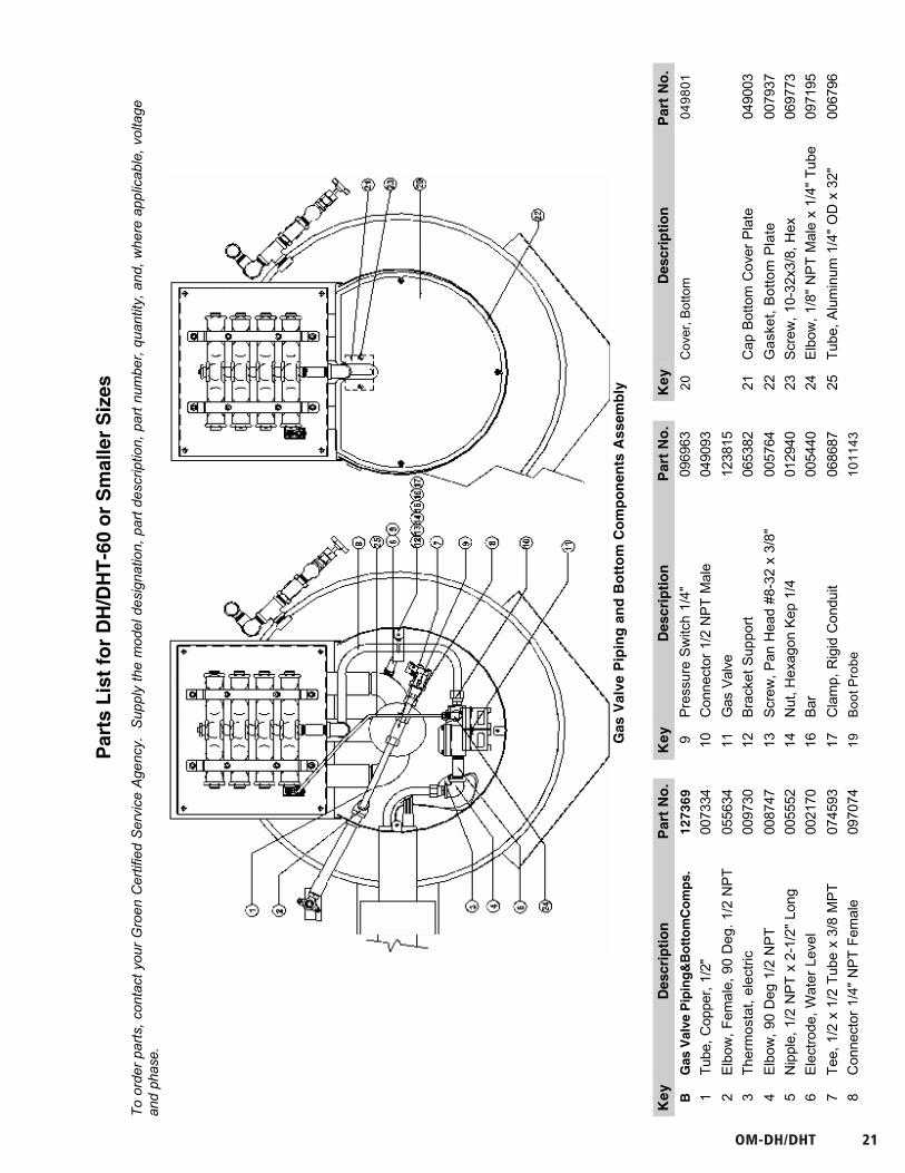
Gas
Val
ve, P
ipin
g &
Bo
tto
m C
om
po
nen
ts
OM-DH/DHT 23
OM-DH
24
OM-DH
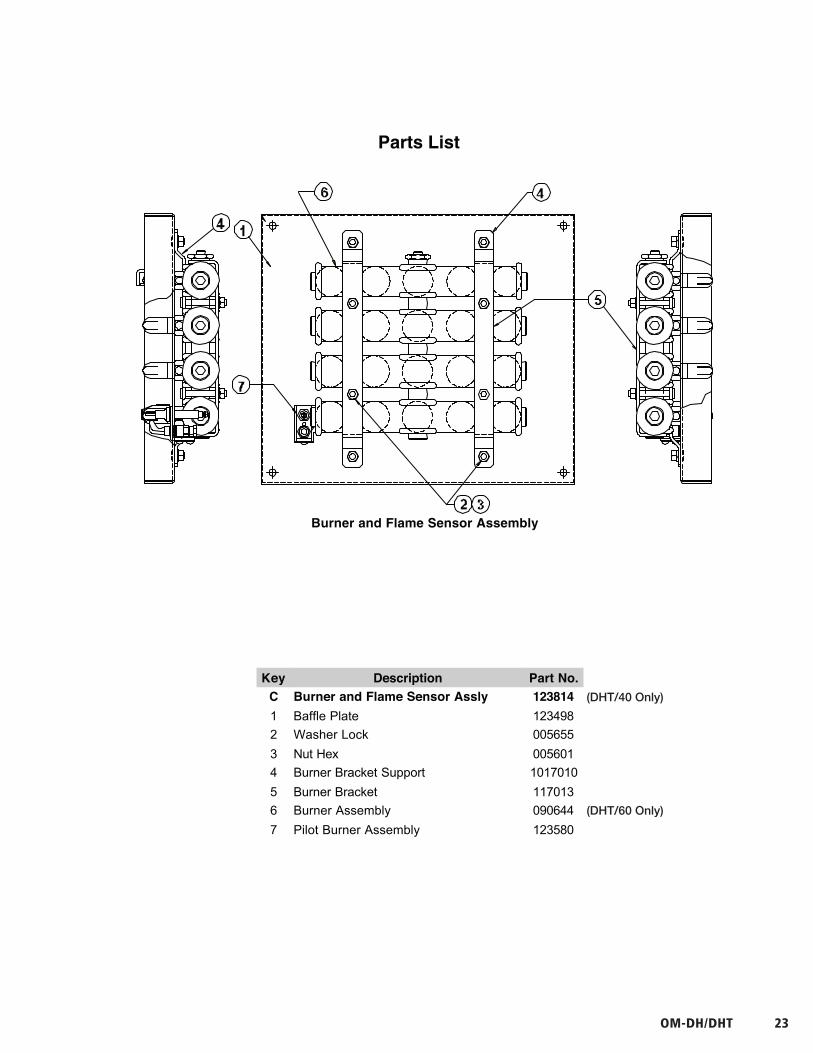
Burner and Flame Sensor Assembly
Parts List
12
3
4
5
OM-DH
25
OM-DH
25
Parts ListTo order parts, contact your Groen Certified Service Agency. Supply the model designation, part description, partnumber, quantity, and, where applicable, voltage and phase.
Key Description Part No. Key Description Part No.C Burner and Flame Sensor Assly 123814 E Flue Stack Assembly 1170341 Baffle Plate 123498 1 Flue, Top Section of Top Plate 117029
2 Washer Lock 005655 2 Flue, Bottom Section of Top Plate 117033
3 Nut Hex 005601 3 Flue, Front Section 117032
4 Burner Bracket Support 1017010 4 Flue, Main Body 117031
5 Burner Bracket 117013 5 Screw, Truss Head 072189
6 Burner Assembly 090644
7 Pilot Burner Assembly 123580
(DHT/40 Only)
(DHT/60 Only)
24 GROEN.COM
OM
-DH
24
OM
-DH
Bu
rner an
d F
lame S
enso
r Assem
bly
Parts L
ist
12
3
4
5
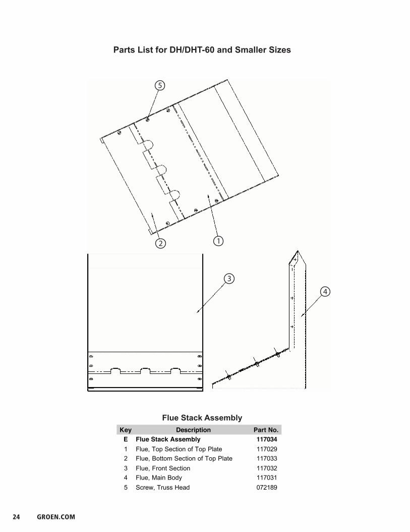
Parts List for DH/DHT-60 and Smaller Sizes
Flue Stack Assembly
OM-DH
25
OM-DH
25
Parts ListTo order parts, contact your Groen Certified Service Agency. Supply the model designation, part description, partnumber, quantity, and, where applicable, voltage and phase.
Key Description Part No. Key Description Part No.C Burner and Flame Sensor Assly 123814 E Flue Stack Assembly 1170341 Baffle Plate 123498 1 Flue, Top Section of Top Plate 117029
2 Washer Lock 005655 2 Flue, Bottom Section of Top Plate 117033
3 Nut Hex 005601 3 Flue, Front Section 117032
4 Burner Bracket Support 1017010 4 Flue, Main Body 117031
5 Burner Bracket 117013 5 Screw, Truss Head 072189
6 Burner Assembly 090644
7 Pilot Burner Assembly 123580

OM-DH/DHT 25
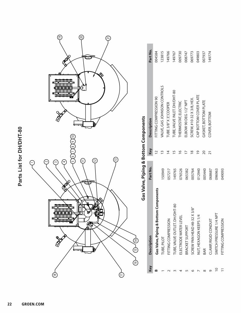
Parts List for DH/DHT-80
2
1
4
3
5
5 8 072189
4 1 149222
3 1 149236
3 1 150927
1 1 149220
ITEM NO. QTY. PART NO. DESCRIPTION
SCREW TRUSS HEAD MACHINED 10-32 X 1/2" L.
FLUE, TOP SECTION
FLUE STACK, BOTTOM SECTION
FLUE, FRONT PANEL. WELDMENT
ASSY. FLUE STACK MAIN BODY
Flue Stack AssemblyKey Description Part No.
E Flue Stack Assembly
1 ASSY. FLUE STACK MAIN BODY 149220
2 FLUE, FRONT PANEL. WELDMENT 150927
3 FLUE STACK, BOTTOM SECTION 149236
4 FLUE, TOP SECTION 149222
5 SCREW TRUSS HEAD MACHINED 10-32 X 1/2” L. 072189
26 GROEN.COM
OM-DH
26
OM-DH
26
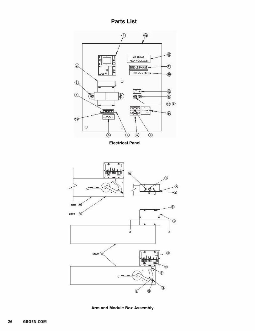
Arm and Module Box Assembly
Electrical Panel
Parts List

OM-DH/DHT 27
OM-DH
27
Parts ListTo order parts, contact your Groen Certified Service Agency. Supply the model designation, part description, partnumber, quantity, and, where applicable, voltage and phase.
Key Description Part No. Key Description Part No.
Electrical Panel 123736 Arm and Module Box Assembly 1277341 Water Level Control 122192 1 Conduit Nut, 1/2" 005487
2 Transformer 75A 24V Sec., 120V Pri 106233 2 Screw #8-32 x 3/8" 005764
Transformer 75A 24V Sec., 208/240VPri
106234 3 Box, Spark Ignition Module 123775
3 Screw, Button Head #8-32 x 0.25 lg 096317 4 Gasket, Ignition Module Box 104941
4 Terminal Block, 2 Pole #4 - #18 AWG 003887 5 Spark Ignition Module 085153
6 Fuse Holder 3AG w/0.1875 quick con. 077854 6 Hex Nut w/shakeproof washer 071289
7 Screw, Round hd #6-32 x 0.1875 lg 058599 7 Conduit, Plastic, male adapter 1/2" 123733
8 Lug, Ground, 14-6 AWG 119829 8 Cover, Ignition Module Box 104948
9 Screw, Round Hd #8-32 x 1.25 lg 005056 9 Hex Nut w/shakeproof washer 069784
10-- Voltage Phase, Ground, Warning & varied 10 Tie Anchor - Screw Mounted 102231
–14 Electrical Supply Labels 11 Cable Tie, 0.140 Wide Locking 086426
15 Fuse, 30 Amp, 3 AG 077853 12 Screw #10=32 x 0.375 long 069773
16 Electrical Panel 123735
17 Nut, Hex, Keps #10-32 w/shakeproof 071256
washer
28 GROEN.COM
OM-DH
28
OM-DH
28
Service Log
Model No. _______________________________ Purchased From _________________________
Serial No. _______________________________ Location ________________________________
Date Purchased __________________________ Date Installed ___________________________
Purchase Order No. _______________________ For Service Call __________________________
Date Service Performed Performed By

OM-DH/DHT 29
OM-DH
29
OM-DH
29
References
CSA INTERNATIONAL8501 East Pleasant Valley RoadCleveland, Ohio 44131
AMERICAN NATIONAL STANDARDS INST., Inc.1430 BroadwayNew York, New York 10018
NATIONAL SANITATION FOUNDATION3475 Plymouth RoadAnn Arbor, Michigan 48106
Z223.1-1984 - National Fuel Gas CodeZ21.30 - Installation Gas Appliances & Piping
KLENZADE SALES CENTER ECOLAB, Inc.370 WabashaSt. Paul, Minnesota 55102
NATIONAL FIRE PROTECTION ASSOCIATION60 Battery march ParkQuincy, Massachusetts 02269
ZEP MANUFACTURING COMPANY1310-T Seaboard Industrial BoulevardAtlanta, Georgia 30318
NFPA/54 -Installation Gas Appliances & PipingNFPA/70 - The National Electric Code
NSF INTERNATIONAL798 N. Dixboro Rd.P.O. Box 130140Ann Arbor, MI 48113-0140
30 GROEN.COM
OM-DH
30
Limited WarrantyTo Commercial Purchasers *
(U.S. & Canadian Sales Only)
Groen Foodservice Equipment ("Groen Equipment") has been skillfully manufactured, carefully inspected andpackaged to meet rigid standards of excellence. Groen warrants its Equipment to be free from defects in materialand workmanship for (12) twelve months with the following conditions and subject to the following limitations.
I. This parts and labor warranty is limited to Groen Equipment sold to the original commercialpurchaser/users (but not original equipment manufacturers), at its original place of installation in thecontinental United States and Canada.
II. Damage during shipment is to be reported to the carrier, is not covered under this warranty, and is thesole responsibility of purchaser/user.
III. Groen, or an authorized service representative, will repair or replace, at Groen's sole election, any GroenEquipment, including but not limited to, drawoff valves, safety valves, gas and electric components,found to be defective during the warranty period. As to warranty service in the territory described above,Groen will absorb labor and portal to portal transportation costs (time & mileage) for the first twelve (12)months from date of installation or fifteen (15) months from date of shipment from Groen.
IV. This warranty does not cover boiler maintenance, calibration, periodic adjustments as specified inoperating instructions or manuals, and consumable parts such as scraper blades, gaskets, packing, etc.,or labor costs incurred for removal of adjacent equipment or objects to gain access to Groen Equipment.This warranty does not cover defects caused by improper installation, abuse, careless operation, orimproper maintenance of equipment. This warranty does not cover damage caused by poor waterquality or improper boiler maintenance.
V. THIS WARRANTY IS EXCLUSIVE AND IS IN LIEU OF ALL OTHER WARRANTIES, EXPRESSED ORIMPLIED, INCLUDING ANY IMPLIED WARRANTY OF MERCHANTABILITY OR FITNESS FOR APARTICULAR PURPOSE, EACH OF WHICH IS HEREBY EXPRESSLY DISCLAIMED. THEREMEDIES DESCRIBED ABOVE ARE EXCLUSIVE AND IN NO EVENT SHALL GROEN BE LIABLEFOR SPECIAL, CONSEQUENTIAL OR INCIDENTAL DAMAGES FOR THE BREACH OR DELAY INPERFORMANCE OF THIS WARRANTY.
VI. Groen Equipment is for commercial use only. If sold as a component of another (O.E.M.) manufacturer'sequipment, or if used as a consumer product, such Equipment is sold AS IS and without any warranty.
* (Covers All Foodservice Equipment Ordered After October 1, 1995)

OM-DH/DHT 31
NOTES

32 GROEN.COM
NOTES

OM-DH/DHT 33
NOTES

PART NUMBER 121050, REV. G (07/10)
1055 Mendell Davis Drive • Jackson MS 39272888-994-7636 • 601-372-3903 • Fax 888-864-7636
unifiedbrands.net
© 2010 Unified Brands. All Rights Reserved. Unified Brands is a wholly-owned subsidiary of Dover Corporation.