this chapter introduces general campus switching and data center
TRANSCRIPT

This chapter introduces general campus switching and data center design considerations. It includes the following sections:
■ Campus Design Considerations
■ Enterprise Campus Design
■ Enterprise Data Center Design Considerations
■ Summary
■ References
■ Case Study: ACMC Hospital Network Campus Design
■ Review Questions

C H A P T E R 4
Designing Basic Campus and Data Center Networks
The availability of multigigabit campus switches gives customers the opportunity to build extremely high-performance, high-reliability networks—if they follow correct network design approaches. Unfortunately, some alternative network design approaches can result in a network that has lower performance, reliability, and manageability.
This chapter describes a hierarchical modular design approach called multilayer design. This chapter examines the designs of the Enterprise Campus and the Enterprise Data Center network infrastructures. First, it addresses general campus design considerations, followed by a discussion of the design of each of the modules and layers within the Enterprise Campus. The chapter concludes with an introduction to design considerations for the Enterprise Data Center.
Campus Design Considerations
The multilayer approach to campus network design combines data link layer and multilayer switching to achieve robust, highly available campus networks. This section discusses factors to consider in a Campus LAN design.
Designing an Enterprise CampusThe Enterprise Campus network is the foundation for enabling business applications, enhancing productivity, and providing a multitude of services to end users. The following three characteristics should be considered when designing the campus network:
■ Network application characteristics: The organizational requirements, services, and applications place stringent requirements on a campus network solution—for example, in terms of bandwidth and delay.
■ Environmental characteristics: The network’s environment includes its geography and the transmission media used.
— The physical environment of the building or buildings influences the design, as do the number of, distribution of, and distance between the network nodes (including end users, hosts, and network devices). Other factors include space, power, and heating, ventilation, and air conditioning support for the network devices.
222 Chapter 4: Designing Basic Campus and Data Center Networks
— Cabling is one of the biggest long-term investments in network deployment. Therefore, transmission media selection depends not only on the required bandwidth and distances, but also on the emerging technologies that might be deployed over the same infrastructure in the future.
■ Infrastructure device characteristics: The characteristics of the network devices selected influence the design (for example, they determine the network’s flexibility) and contribute to the overall delay. Trade-offs between data link layer switching—based on media access control (MAC) addresses—and multilayer switching—based on network layer addresses, transport layer, and application awareness—need to be considered.
— High availability and high throughput are requirements that might require consideration throughout the infrastructure.
— Most Enterprise Campus designs use a combination of data link layer switching in the access layer and multilayer switching in the distribution and core layers.
The following sections examine these factors.
Network Application Characteristics and ConsiderationsThe network application’s characteristics and requirements influence the design in many ways. The applications that are critical to the organization, and the network demands of these applications, determine enterprise traffic patterns inside the Enterprise Campus network, which influences bandwidth usage, response times, and the selection of the transmission medium.
Different types of application communication result in varying network demands. The following sections review four types of application communication:
■ Peer-peer
■ Client–local server
■ Client–Server Farm
■ Client–Enterprise Edge server
Peer-Peer Applications
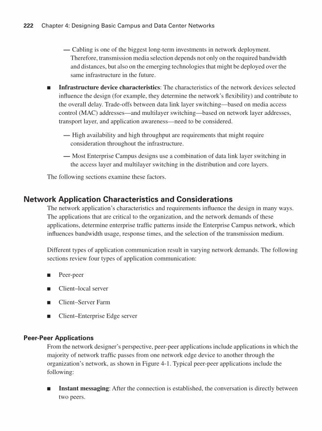
From the network designer’s perspective, peer-peer applications include applications in which the majority of network traffic passes from one network edge device to another through the organization’s network, as shown in Figure 4-1. Typical peer-peer applications include the following:
■ Instant messaging: After the connection is established, the conversation is directly between two peers.

Campus Design Considerations 223
■ IP phone calls: Two peers establish communication with the help of an IP telephony manager; however, the conversation occurs directly between the two peers when the connection is established. The network requirements of IP phone calls are strict because of the need for quality of service (QoS) treatment to minimize delay and variation in delay (jitter).
■ File sharing: Some operating systems and applications require direct access to data on other workstations.
■ Videoconference systems: Videoconferencing is similar to IP telephony; however, the network requirements are usually higher, particularly related to bandwidth consumption and QoS.
Figure 4-1 Peer-Peer Applications
Client–Local Server Applications
Historically, clients and servers were attached to a network device on the same LAN segment and followed the 80/20 workgroup rule for client/server applications. This rule indicates that 80 percent of the traffic is local to the LAN segment and 20 percent leaves the segment.
With increased traffic on the corporate network and a relatively fixed location for users, an organization might split the network into several isolated segments, as shown in Figure 4-2. Each of these segments has its own servers, known as local servers, for its application. In this scenario, servers and users are located in the same VLAN, and department administrators manage and control the servers. The majority of department traffic occurs in the same segment, but some data exchange (to a different VLAN) happens over the campus backbone. The bandwidth requirements
NOTE QoS is discussed in the later section “QoS Considerations in LAN Switches.”

224 Chapter 4: Designing Basic Campus and Data Center Networks
for traffic passing to another segment typically are not crucial. For example, traffic to the Internet goes through a common segment and has lower performance requirements than traffic to the local segment servers.
Figure 4-2 Client–Local Server Application
Client–Server Farm Applications
Large organizations require their users to have fast, reliable, and controlled access to critical applications.
Because high-performance multilayer switches have an insignificant switch delay, and because of the reduced cost of network bandwidth, locating the servers centrally rather than in the workgroup is technically feasible and reduces support costs.
To fulfill these demands and keep administrative costs down, the servers are located in a common Server Farm, as shown in Figure 4-3. Using a Server Farm requires a network infrastructure that is highly resilient (providing security) and redundant (providing high availability) and that provides adequate throughput. High-end LAN switches with the fastest LAN technologies, such as Gigabit Ethernet, are typically deployed in such an environment.
BuildingAccess
BuildingAccess
BuildingDistribution/
CampusCore

Campus Design Considerations 225
Figure 4-3 Client–Server Farm Application
In a large organization, application traffic might have to pass across more than one wiring closet, LAN, or VLAN to reach servers in a Server Farm. Client–Server Farm applications apply the 20/80 rule, where only 20 percent of the traffic remains on the local LAN segment, and 80 percent leaves the segment to reach centralized servers, the Internet, and so on. Such applications include the following:
■ Organizational mail servers (such as Microsoft Exchange)
■ Common file servers (such as Microsoft and Sun)
■ Common database servers for organizational applications (such as Oracle)
BuildingAccess
BuildingAccess
BuildingDistribution/CampusCore
Server Farm
226 Chapter 4: Designing Basic Campus and Data Center Networks
Client–Enterprise Edge Applications
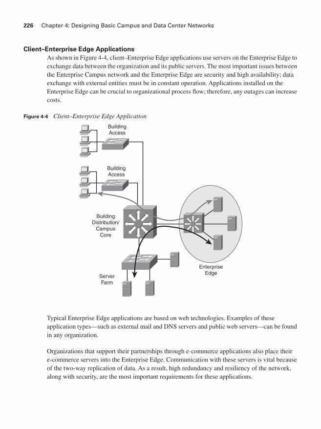
As shown in Figure 4-4, client–Enterprise Edge applications use servers on the Enterprise Edge to exchange data between the organization and its public servers. The most important issues between the Enterprise Campus network and the Enterprise Edge are security and high availability; data exchange with external entities must be in constant operation. Applications installed on the Enterprise Edge can be crucial to organizational process flow; therefore, any outages can increase costs.
Figure 4-4 Client–Enterprise Edge Application
Typical Enterprise Edge applications are based on web technologies. Examples of these application types—such as external mail and DNS servers and public web servers—can be found in any organization.
Organizations that support their partnerships through e-commerce applications also place their e-commerce servers into the Enterprise Edge. Communication with these servers is vital because of the two-way replication of data. As a result, high redundancy and resiliency of the network, along with security, are the most important requirements for these applications.
BuildingAccess
BuildingAccess
EnterpriseEdge
BuildingDistribution/
CampusCore
ServerFarm

Campus Design Considerations 227
Application Requirements
Table 4-1 lists the types of application communication and compares their requirements with respect to some important network parameters. The following sections discuss these parameters.
Connectivity
The wide use of LAN switching at Layer 2 has revolutionized local-area networking and has resulted in increased performance and more bandwidth for satisfying the requirements of new organizational applications. LAN switches provide this performance benefit by increasing bandwidth and throughput for workgroups and local servers.
Throughput
The required throughput varies from application to application. An application that exchanges data between users in the workgroup usually does not require a high throughput network infrastructure. However, organizational-level applications usually require a high-capacity link to the servers, which are usually located in the Server Farm.
Applications located on servers in the Enterprise Edge are normally not as bandwidth-consuming as applications in the Server Farm, but they might require high availability and security features.
Table 4-1 Network Application Requirements
Parameter Peer-Peer
Client–Local
Server
Client–
Server Farm
Client–Enterprise
Edge Servers
Connectivity type
Shared Switched Switched Switched Switched
Total required throughput
Low Medium to high
Medium High Medium
High availability Low Low Medium High High
Total network cost
Low Low Medium High Medium
NOTE Using shared media for peer-to-peer communication is suitable only in a limited scope, typically when the number of client workstations is very low (for example, with four or fewer workstations in small home offices).
NOTE Peer-peer communication, especially in the case of frequent file transfers, could be intensive, and the total throughput requirements can be high.

228 Chapter 4: Designing Basic Campus and Data Center Networks
High Availability
The high availability of an application is a function of the application and the entire network between a client workstation and a server located in the network. Although the network design primarily determines the network’s availability, the individual components’ mean time between failures (MTBF) is a factor. Redundancy in the Building Distribution and Campus Core layers is recommended.
Total Network Cost
Depending on the application and the resulting network infrastructure, the cost varies from low in a peer-peer environment to high in a network with redundancy in the Building Distribution, Campus Core, and Server Farm. In addition to the cost of duplicate components for redundancy, costs include the cables, routers, switches, software, and so forth.
Environmental Characteristics and ConsiderationsThe campus environment, including the location of the network nodes, the distance between the nodes, and the transmission media used, influences the network topology. This section examines these considerations.
Network Geography Considerations
The location of Enterprise Campus nodes and the distances between them determine the network’s geography.
Nodes, including end-user workstations and servers, can be located in one or multiple buildings. Based on the location of nodes and the distance between them, the network designer decides which technology should interconnect them based on the required maximum speed, distance, and so forth.
Consider the following structures with respect to the network geography:
■ Intrabuilding
■ Interbuilding
■ Distant remote building
These geographic structures, described in the following sections, serve as guides to help determine Enterprise Campus transmission media and the logical modularization of the Enterprise Campus network.

Campus Design Considerations 229
Intrabuilding Structure
An intrabuilding campus network structure provides connectivity for all end nodes located in the same building and gives them access to the network resources. The Building Access and Building Distribution layers are typically located in the same building.
User workstations are usually attached to the Building Access switches in the floor wiring closet with twisted-pair copper cables. Wireless LANs (WLAN) can also be used to provide intrabuilding connectivity, enabling users to establish and maintain a wireless network connection throughout—or between—buildings, without the limitations of wires or cables.
Access layer switches usually connect to the Building Distribution switches over optical fiber, providing better transmission performance and less sensitivity to environmental disturbances than copper. Depending on the connectivity requirements to resources in other parts of the campus, the Building Distribution switches may be connected to Campus Core switches.
Interbuilding Structure
As shown in Figure 4-5, an interbuilding network structure provides connectivity between the individual campus buildings’ central switches (in the Building Distribution and/or Campus Core layers). These buildings are usually in close proximity, typically only a few hundred meters to a few kilometers apart.
Figure 4-5 Interbuilding Network Structure
NOTE WLANs are covered in Chapter 9, “Wireless Network Design Considerations.”
BuildingAccess
BuildingAccess
Building A Building B
BuildingDistribution/CampusCore

230 Chapter 4: Designing Basic Campus and Data Center Networks
Because the nodes in all campus buildings usually share common devices such as servers, the demand for high-speed connectivity between the buildings is high. Within a campus, companies might deploy their own physical transmission media. To provide high throughput without excessive interference from environmental conditions, optical fiber is the medium of choice between the buildings.
Depending on the connectivity requirements to resources in other parts of the campus, the Building Distribution switches might be connected to Campus Core switches.
Distant Remote Building Structure
When connecting buildings at distances that exceed a few kilometers (but still within a metropolitan area), the most important factor to consider is the physical media. The speed and cost of the network infrastructure depend heavily on the media selection.
If the bandwidth requirements are higher than the physical connectivity options can support, the network designer must identify the organization’s critical applications and then select the equipment that supports intelligent network services—such as QoS and filtering capabilities—that allow optimal use of the bandwidth.
Some companies might own their media, such as fiber, microwave, or copper lines. However, if the organization does not own physical transmission media to certain remote locations, the Enterprise Campus must connect through the Enterprise Edge using connectivity options from public service providers, such as traditional WAN links or Metro Ethernet.
The risk of downtime and the service level agreements available from the service providers must also be considered. For example, inexpensive but unreliable and slowly repaired fiber is not desirable for mission-critical applications.
Transmission Media Considerations
An Enterprise Campus can use various physical media to interconnect devices. The type of cable is an important consideration when deploying a new network or upgrading an existing one. Cabling infrastructure represents a long-term investment—it is usually installed to last for ten years or more. The cost of the medium (including installation costs) and the available budget must be considered in addition to the technical characteristics such as signal attenuation and electromagnetic interference.
NOTE Chapter 5, “Designing Remote Connectivity,” includes further discussion of connecting remote locations.
Campus Design Considerations 231
A network designer must be aware of physical media characteristics, because they influence the maximum distance permitted between devices and the network’s maximum transmission speed. Twisted-pair cables (copper), optical cables (fiber), and wireless (satellite, microwave, and Institute of Electrical and Electronics Engineers [IEEE] 802.11 LANs) are the most common physical transmission media used in modern networks.
Copper
Twisted-pair cables consist of four pairs of isolated wires that are wrapped together in plastic cable. With unshielded twisted-pair (UTP), no additional foil or wire is wrapped around the core wires. This makes these wires less expensive, but also less immune to external electromagnetic influences than shielded twisted-pair cables. Twisted-pair cabling is widely used to interconnect workstations, servers, or other devices from their network interface card (NIC) to the network connector at a wall outlet.
The characteristics of twisted-pair cable depend on the quality of the material from which they are made. As a result, twisted-pair cables are sorted into categories. Category 5 or greater is recommended for speeds of 100 megabits per second (Mbps) or higher. Category 6 is recommended for Gigabit Ethernet. Because of the possibility of signal attenuation in the wires, the maximum cable length is usually limited to 100 meters. One reason for this length limitation is collision detection. If one PC starts to transmit and another PC is more than 100 meters away, the second PC might not detect the signal on the wire and could therefore start to transmit at the same time, causing a collision on the wire.
One of the main considerations in network cabling design is electromagnetic interference. Due to high susceptibility to interference, twisted pair is not suitable for use in environments with electromagnetic influences. Similarly, twisted pair is not appropriate for environments that can be affected by the interference created by the cable itself.
Distances longer than 100 meters may require Long-Reach Ethernet (LRE). LRE is Cisco-proprietary technology that runs on voice-grade copper wires; it allows higher distances than traditional Ethernet and is used as an access technology in WANs. Chapter 5 further describes LRE.
NOTE Some security issues are also associated with electromagnetic interference. Hackers with access to the cabling infrastructure might eavesdrop on the traffic carried across UTP, because these cables emit electromagnetic signals that can be detected.

232 Chapter 4: Designing Basic Campus and Data Center Networks
Optical Fiber
Typical requirements that lead to the selection of optical fiber cable as a transmission medium include distances longer than 100 meters and immunity to electromagnetic interference. Different types of optical cable exist; the two main types are multimode (MM) and single-mode (SM).
Multimode fiber is optical fiber that carries multiple light waves or modes concurrently, each at a slightly different reflection angle within the optical fiber core. Because modes tend to disperse over longer lengths (modal dispersion), MM fiber transmission is used for relatively short distances. Typically, LEDs are used with MM fiber. The typical diameter of an MM fiber is 50 or 62.5 micrometers.
Single-mode (also known as monomode) fiber is optical fiber that carries a single wave (or laser) of light. Lasers are typically used with SM fiber. The typical diameter of an SM fiber core is between 2 and 10 micrometers. Single-mode fiber limits dispersion and loss of light, and therefore allows for higher transmission speeds, but it is more expensive than multimode fiber.
Both MM and SM cables have lower loss of signal than copper cable. Therefore, optical cables allow longer distances between devices. Optical fiber cable has precise production and installation requirements; therefore, it costs more than twisted-pair cable.
Optical fiber requires a precise technique for cable coupling. Even a small deviation from the ideal position of optical connectors can result in either a loss of signal or a large number of frame losses. Careful attention during optical fiber installation is imperative because of the traffic’s high sensitivity to coupling misalignment. In environments where the cable does not consist of a single fiber from point to point, coupling is required, and loss of signal can easily occur.
Wireless
The inherent nature of wireless is that it does not require wires to carry information across geographic areas that are otherwise prohibitive to connect. WLANs can either replace a traditional wired network or extend its reach and capabilities. In-building WLAN equipment includes access points (AP) that perform functions similar to wired networking hubs, and PC client adapters. APs are distributed throughout a building to expand range and functionality for wireless clients. Wireless bridges and APs can also be used for interbuilding connectivity and outdoor wireless client access.
Wireless clients supporting IEEE 802.11g allow speeds of up to 54 Mbps in the 2.4-GHz band over a range of about 100 feet. The IEEE 802.11b standard supports speeds of up to 11 Mbps in the 2.4-GHz band. The IEEE 802.11a standard supports speeds of up to 54 Mbps in the 5-GHz band.
NOTE Wireless issues are discussed further in Chapter 9.

Campus Design Considerations 233
Transmission Media Comparison
Table 4-2 presents various characteristics of the transmission media types.
1Wireless is half-duplex, so effective bandwidth will be no more than half of this rate.
The parameters listed in Table 4-2 are as follows:
■ Distance: The maximum distance between network devices (such as workstations, servers, printers, and IP phones) and network nodes, and between network nodes. The distances supported with fiber vary, depending on whether it supports Fast Ethernet or Gigabit Ethernet, the type of fiber used, and the fiber interface used.
■ Bandwidth: The required bandwidth in a particular segment of the network, or the connection speed between the nodes inside or outside the building.
■ Price: Along with the price of the medium, the installation cost must be considered. For example, fiber installation costs are significantly higher than copper installation costs because of strict requirements for optical cable coupling.
Table 4-2 Transmission Media Type Characteristics
Parameter
Copper
Twisted Pair MM Fiber SM Fiber Wireless
Distance(range)
Up to 100 meters Up to 2 kilometers (km) (Fast Ethernet)
Up to 550 m (Gigabit Ethernet)
Up to 300 m (10 Gigabit Ethernet)
Up to 10 km (Fast Ethernet)
Up to 5 km (Gigabit Ethernet)
Up to 80 km (10 Gigabit Ethernet)
Up to 500 m at 1 Mbps
Bandwidth Up to 10 Gigabits per second (Gbps)
Up to 10 Gbps Up to 10 Gbps or higher
Up to 54 Mbps1
Price Inexpensive Moderate Moderate to expensive
Moderate
Deployment area
Wiring closet Internode or interbuilding
Internode or interbuilding
Internode or interbuilding
NOTE The wireless throughput is significantly less than its maximum data rate due to the half-duplex nature of radio frequency technology.

234 Chapter 4: Designing Basic Campus and Data Center Networks
■ Deployment area: Indicates whether wiring is for wiring closet only (where users access the network), for internode, or for interbuilding connections.
When deploying devices in an area with high electrical or magnetic interference—for example, in an industrial environment—you must pay special attention to media selection. In such environments, the disturbances might interfere with data transfer and therefore result in an increased number of frame errors. Electrical grounding can isolate some external disturbance, but the additional wiring increases costs. Fiber- optic installation is the only reasonable solution for such networks.
Cabling Example
Figure 4-6 illustrates a typical campus network structure. End devices such as workstations, IP phones, and printers are no more than 100 m away from the LAN switch. UTP wiring can easily handle the required distance and speed; it is also easy to set up, and the price-performance ratio is reasonable.
Figure 4-6 Campus Networks Use Many Different Types of Cables
NOTE The distances shown in the figure are for a sample network; however, the maximum distance supported varies depending on the fiber interface used.
UTP CableFast Ethernet: <100 m
Fiber MM
Fiber SMGigabit Ethernet: <5 km
Fiber MMGE: <200 m

Campus Design Considerations 235
Optical fiber cables handle the higher speeds and distances that may be required among switch devices. MM optical cable is usually satisfactory inside the building. Depending on distance, organizations use MM or SM optical for interbuilding communication cable. If the distances are short (up to 500 m), MM fiber is a more reasonable solution for speeds up to 1 Gbps.
However, an organization can install SM fiber if its requirements are for longer distances, or if there are plans for future higher speeds (for example, 10 Gbps).
Infrastructure Device Characteristics and ConsiderationsNetwork end-user devices are commonly connected using switched technology rather than using a shared media segment. Switched technology provides dedicated network bandwidth for each device on the network. Switched networks can support network infrastructure services, such as QoS, security, and management; a shared media segment cannot support these features.
In the past, LAN switches were Layer 2–only devices. Data link layer (Layer 2) switching supports multiple simultaneous frame flows. Multilayer switching performs packet switching and several functions at Layer 3 and at higher Open Systems Interconnection (OSI) layers and can effectively replace routers in the LAN switched environment. Deciding whether to deploy pure data link layer switches or multilayer switches in the enterprise network is not a trivial decision. It requires a full understanding of the network topology and user demands.
NOTE Selecting the less expensive type of fiber might satisfy a customer’s current needs, but this fiber might not meet the needs of future upgrades or equipment replacement. Replacing cable can be very expensive. Planning with future requirements in mind might result in higher initial costs but lower costs in the long run.
KEY
POINT
The difference between data link layer and multilayer switching is the type of information used inside the frame to determine the correct output interface.
Data link layer switching forwards frames based on data link layer information (the MAC address), whereas multilayer switching forwards frames based on network layer information (such as IP address).
Multilayer switching is hardware-based switching and routing integrated into a single platform. See the upcoming “Multilayer Switching and Cisco Express Forwarding” section for implementation details.
236 Chapter 4: Designing Basic Campus and Data Center Networks
When deciding on the type of switch to use and the features to be deployed in a network, consider the following factors:
■ Infrastructure service capabilities: The network services that the organization requires (IP multicast, QoS, and so on).
■ Size of the network segments: How the network is segmented and how many end devices will be connected, based on traffic characteristics.
■ Convergence time: The maximum amount of time the network will be unavailable in the event of network outages.
■ Cost: The budget for the network infrastructure. Note that multilayer switches are typically more expensive than their Layer 2 counterparts; however, multilayer functionality can be obtained by adding cards and software to a modular Layer 2 switch.
The following sections examine the following infrastructure characteristics: convergence time, multilayer switching and Cisco Express Forwarding, IP multicast, QoS, and load sharing.
Convergence Time
Loop-prevention mechanisms in a Layer 2 topology cause the Spanning Tree Protocol (STP) to take between 30 and 50 seconds to converge. To eliminate STP convergence issues in the Campus Core, all the links connecting core switches should be routed links, not VLAN trunks. This also limits the broadcast and failure domains.
In the case where multilayer switching is deployed everywhere, convergence is within seconds (depending on the routing protocol implemented) because all the devices detect their connected link failure immediately and act on it promptly (sending respective routing updates).
In a mixed Layer 2 and Layer 3 environment, the convergence time depends not only on the Layer 3 factors (including routing protocol timers such as hold-time and neighbor loss detection), but also on the STP convergence.
Using multilayer switching in a structured design reduces the scope of spanning-tree domains. It is common to use a routing protocol, such as Enhanced Interior Gateway Routing Protocol (EIGRP) or Open Shortest Path First (OSPF), to handle load balancing, redundancy, and recovery in the Campus Core.
NOTE STP tools are covered in the section “The Cisco STP Toolkit” later in this chapter.

Campus Design Considerations 237
Multilayer Switching and Cisco Express Forwarding
As noted in Chapter 3, “Structuring and Modularizing the Network,” in this book the term multilayer switching denotes a switch’s generic capability to use information at different protocol layers as part of the switching process; the term Layer 3 switching is a synonym for multilayer switching in this context.
The use of protocol information from multiple layers in the switching process is implemented in two different ways within Cisco switches. The first way is called multilayer switching (MLS), and the second way is called Cisco Express Forwarding.
Multilayer Switching
Multilayer switching, as its name implies, allows switching to take place at different protocol layers. Switching can be performed only on Layers 2 and 3, or it can also include Layer 4. MLS is based on network flows.
The three major components of MLS are as follows:
■ MLS Route Processor (MLS-RP): The MLS-enabled router that performs the traditional function of routing between subnets
■ MLS Switching Engine (MLS-SE): The MLS-enabled switch that can offload some of the packet-switching functionality from the MLS-RP
■ Multilayer Switching Protocol (MLSP): Used by the MLS-RP and the MLS-SE to communicate with each other
KEY
POINT
A network flow is a unidirectional sequence of packets between a source and a destination. Flows can be very specific. For example, a network flow can be identified by source and destination IP addresses, protocol numbers, and port numbers as well as the interface on which the packet enters the switch.
KEY
POINT
MLS allows communication between two devices that are in different VLANs (on different subnets), that are connected to the same MLS-SE, and that share a common MLS-RP. The communication bypasses the MLS-RP and instead uses the MLS-SE to relay the packets, thus improving overall performance.

238 Chapter 4: Designing Basic Campus and Data Center Networks
MLS History
Pure MLS is an older technique used on the Catalyst 5500 switches with a Route Switch Module (manually configured as the MLS-RP) and a Supervisor Engine III with a NetFlow Feature Card (manually configured as the MLS-SE). The first packet of a flow is routed by the MLS-RP, whereas the MLS-SE records (caches) all flow, or header, information; all subsequent packets in the identical flow are hardware-switched by the MLS-SE.
Most of Cisco’s modern multilayer switches use Cisco Express Forwarding–based multilayer switching (as described in the next section), using hardware integrated in the switch platform.
Cisco Express Forwarding
Cisco Express Forwarding, like MLS, aims to speed the data routing and forwarding process in a network. However, the two methods use different approaches.
Cisco Express Forwarding uses two components to optimize the lookup of the information required to route packets: the Forwarding Information Base (FIB) for the Layer 3 information and the adjacency table for the Layer 2 information.
Cisco Express Forwarding creates an FIB by maintaining a copy of the forwarding information contained in the IP routing table. The information is indexed, so it is quick to search for matching entries as packets are processed. Whenever the routing table changes, the FIB is also changed so that it always contains up-to-date paths. A separate routing cache is not required.
The adjacency table contains Layer 2 frame header information, including next-hop addresses, for all FIB entries. Each FIB entry can point to multiple adjacency table entries—for example, if two paths exist between devices for load balancing.
After a packet is processed and the route is determined from the FIB, the Layer 2 next-hop and header information is retrieved from the adjacency table, and the new frame is created to encapsulate the packet.
Cisco Express Forwarding can be enabled on a router (for example, on a Cisco 7600 Series router) or on a switch with Layer 3 functionality (such as the Catalyst 6500 Series switch).
NOTE Not all Catalyst switches support Cisco Express Forwarding. See the specific product documentation on the Cisco website for device support information.

Campus Design Considerations 239
IP Multicast
A traditional IP network is not efficient when sending the same data to many locations; the data is sent in unicast packets and therefore is replicated on the network for each destination. For example, if a CEO’s annual video address is sent out on a company’s network for all employees to watch, the same data stream must be replicated for each employee. Obviously, this would consume many resources, including precious WAN bandwidth.
IP multicast technology enables networks to send data to a group of destinations in the most efficient way. The data is sent from the source as one stream; this single data stream travels as far as it can in the network. Devices replicate the data only if they need to send it out on multiple interfaces to reach all members of the destination group.
Multicast groups are identified by Class D IP addresses, which are in the range from 224.0.0.0 to 239.255.255.255. IP multicast involves some new protocols for network devices, including two for informing network devices which hosts require which multicast data stream and one for determining the best way to route multicast traffic. These three protocols are described in the following sections.
Internet Group Management Protocol and Cisco Group Management Protocol
Internet Group Management Protocol (IGMP) is used between hosts and their local routers. Hosts register with the router to join (and leave) specific multicast groups; the router then knows that it needs to forward the data stream destined for a specific multicast group to the registered hosts.
In a typical network, hosts are not directly connected to routers but are connected to a Layer 2 switch, which is in turn connected to the router. IGMP is a network layer (Layer 3) protocol. Consequently, Layer 2 switches do not participate in IGMP and therefore are not aware of which hosts attached to them might be part of a particular multicast group. By default, Layer 2 switches flood multicast frames to all ports (except the port from which the frame originated), which means that all multicast traffic received by a switch would be sent out on all ports, even if only one device on one port required the data stream. Cisco therefore developed Cisco Group Management Protocol (CGMP), which is used between switches and routers. The routers tell each of their directly connected switches about IGMP registrations that were received from hosts through the switch—in other words, from hosts accessible through the switch. The switch then forwards the multicast traffic only to ports that those requesting hosts are on, rather than flooding the data to all ports. Switches, including non-Cisco switches, can alternatively use IGMP snooping to eavesdrop on the IGMP messages sent between routers and hosts to learn similar information.
Figure 4-7 illustrates the interaction of these two protocols. Hosts A and D register, using IGMP, to join the multicast group to receive data from the server. The router informs both switches of these registrations using CGMP. When the router forwards the multicast data to the hosts, the

240 Chapter 4: Designing Basic Campus and Data Center Networks
switches ensure that the data goes out of only the ports on which hosts A and D are connected. The ports on which hosts B and C are connected do not receive the multicast data.
Figure 4-7 IGMP and CGMP Tell Network Devices Which Hosts Want Which Multicast Data
Protocol-Independent Multicast Routing Protocol
Protocol-Independent Multicast (PIM) is used by routers that forward multicast packets. The protocol-independent part of the name indicates that PIM is independent of the unicast routing protocol (for example, EIGRP or OSPF) running in the network. PIM uses the normal routing table, populated by the unicast routing protocol, in its multicast routing calculations.
Unlike other routing protocols, no routing updates are sent between PIM routers.
NOTE EIGRP, OSPF, and so forth are called unicast routing protocols because they are used to create and maintain unicast routing information in the routing table. Recall, though, that they use multicast packets (or broadcast packets in some protocols) to send their routing update traffic. Note that a variant of OSPF, called multicast OSPF, supports multicast routing; Cisco routers do not support multicast OSPF.
A B C D
Server
IGMP (join)IGMP (join)
CGMP CGMP
Multicast Data

Campus Design Considerations 241
When a router forwards a unicast packet, it looks up the destination address in its routing table and forwards the packet out of the appropriate interface. However, when forwarding a multicast packet, the router might have to forward the packet out of multiple interfaces, toward all the receiving hosts. Multicast-enabled routers use PIM to dynamically create distribution trees that control the path that IP multicast traffic takes through the network to deliver traffic to all receivers.
The following two types of distribution trees exist:
■ Source tree: A source tree is created for each source sending to each multicast group. The source tree has its root at the source and has branches through the network to the receivers.
■ Shared tree: A shared tree is a single tree that is shared between all sources for each multicast group. The shared tree has a single common root, called a rendezvous point (RP).
Multicast routers consider the source address of the multicast packet as well as the destination address, and they use the distribution tree to forward the packet away from the source and toward the destination. Forwarding multicast traffic away from the source, rather than to the receiver, is called Reverse Path Forwarding (RPF). To avoid routing loops, RPF uses the unicast routing table to determine the upstream (toward the source) and downstream (away from the source) neighbors and ensures that only one interface on the router is considered to be an incoming interface for data from a specific source. For example, data received on one router interface and forwarded out another interface can loop around the network and come back into the same router on a different interface; RPF ensures that this data is not forwarded again.
PIM operates in one of the following two modes:
■ Sparse mode: This mode uses a “pull” model to send multicast traffic. Sparse mode uses a shared tree and therefore requires an RP to be defined. Sources register with the RP. Routers along the path from active receivers that have explicitly requested to join a specific multicast group register to join that group. These routers calculate, using the unicast routing table, whether they have a better metric to the RP or to the source itself; they forward the join message to the device with the better metric.
■ Dense mode: This mode uses a “push” model that floods multicast traffic to the entire network. Dense mode uses source trees. Routers that have no need for the data (because they are not connected to receivers that want the data or to other routers that want it) request that the tree be pruned so that they no longer receive the data.
QoS Considerations in LAN Switches
A campus network transports many types of applications and data, which might include high-quality video and delay-sensitive data (such as real-time voice). Bandwidth-intensive applications enhance many business processes but might also stretch network capabilities and resources.

242 Chapter 4: Designing Basic Campus and Data Center Networks
Networks must provide secure, predictable, measurable, and sometimes guaranteed services. Achieving the required QoS by managing delay, delay variation (jitter), bandwidth, and packet loss parameters on a network can be the key to a successful end-to-end business solution. QoS mechanisms are techniques used to manage network resources.
The assumption that a high-capacity, nonblocking switch with multigigabit backplanes never needs QoS is incorrect. Many networks or individual network elements are oversubscribed; it is easy to create scenarios in which congestion can potentially occur and that therefore require some form of QoS. The sum of the bandwidths on all ports on a switch where end devices are connected is usually greater than that of the uplink port; when the access ports are fully used, congestion on the uplink port is unavoidable. Uplinks from the Building Access layer to the Building Distribution layer, or from the Building Distribution layer to the Campus Core layer, most often require QoS. Depending on traffic flow and uplink oversubscription, bandwidth is managed with QoS mechanisms on the Building Access, Building Distribution, or even Campus Core switches.
QoS Mechanisms
QoS mechanisms or tools implemented on LAN switches include the following:
■ Classification and marking: Packet classification is the process of partitioning traffic into multiple priority levels, or classes of service. Information in the frame or packet header is inspected, and the frame’s priority is determined. Marking is the process of changing the priority or class of service (CoS) setting within a frame or packet to indicate its classification.
For IEEE 802.1Q frames, the 3 user priority bits in the Tag field—commonly referred to as the 802.1p bits—are used as CoS bits. However, Layer 2 markings are not useful as end-to-end QoS indicators, because the medium often changes throughout a network (for example, from Ethernet to a Frame Relay WAN). Thus, Layer 3 markings are required to support end-to-end QoS.
For IPv4, Layer 3 marking can be done using the 8-bit type of service (ToS) field in the packet header. Originally, only the first 3 bits were used; these bits are called the IP Precedence bits.Because 3 bits can specify only eight marking values, IP precedence does not allow a granular classification of traffic. Thus, more bits are now used: the first 6 bits in the TOS field are now known as the DiffServ Code Point (DSCP) bits.

Campus Design Considerations 243
■ Congestion management: Queuing: Queuing separates traffic into various queues or buffers; the marking in the frame or packet can be used to determine which queue traffic goes in. A network interface is often congested (even at high speeds, transient congestion is observed); queuing techniques ensure that traffic from the critical applications is forwarded appropriately. For example, real-time applications such as VoIP and stock trading might have to be forwarded with the least latency and jitter.
■ Congestion Management: Scheduling: Scheduling is the process that determines the order in which queues are serviced.
■ Policing and shaping: Policing and shaping tools identify traffic that violates some threshold level and reduces a stream of data to a predetermined rate or level. Traffic shaping buffers the frames for a short time. Policing simply drops or lowers the priority of the frame that is out of profile.
QoS in LAN Switches
When configuring QoS features, classify the specific network traffic, prioritize and mark it according to its relative importance, and use congestion management and policing and shaping techniques to provide preferential treatment. Implementing QoS in the network makes network performance more predictable and bandwidth use more effective. Figure 4-8 illustrates where the various categories of QoS may be implemented in LAN switches.
NOTE Two models exist for deploying end-to-end QoS in a network for traffic that is not suitable for best-effort service: Integrated Services (IntServ) and Differentiated Services (DiffServ). End-to-end QoS means that the network provides the level of service required by traffic throughout the entire network, from one end to the other.
With IntServ, an application requests services from the network, and the network devices confirm that they can meet the request, before any data is sent. The data from the application is considered a flow of packets.
In contrast, with DiffServ, each packet is marked as it enters the network based on the type of traffic that it contains. The network devices then use this marking to determine how to handle the packet as it travels through the network. The DSCP bits are used to implement the DiffServ model.
NOTE Later chapters in this book describe two other QoS mechanisms: congestion avoidance and link efficiency techniques.

244 Chapter 4: Designing Basic Campus and Data Center Networks
Figure 4-8 QoS in LAN Switches
Data link layer switches are commonly used in the Building Access layer. Because they do not have knowledge of Layer 3 or higher information, these switches provide QoS classification and marking based only on the switch’s input port or MAC address. For example, traffic from a particular host can be defined as high-priority traffic on the uplink port. Multilayer switches may be used in the Building Access layer if Layer 3 services are required.
Building Distribution layer, Campus Core layer, and Server Farm switches are typically multilayer switches and can provide QoS selectively—not only on a port basis, but also according to higher-layer parameters, such as IP addresses, port numbers, or QoS bits in the IP packet. These switches make QoS classification more selective by differentiating the traffic based on the application. QoS in distribution and core switches must be provided in both directions of traffic flow. The policing for certain traffic is usually implemented on the distribution layer switches.
Load Sharing in Layer 2 and Layer 3 Switches
Layer 2 and Layer 3 switches handle load sharing differently.
Layer 2 Load Sharing
Because Layer 2 switches are aware of only MAC addresses, they cannot perform any intelligent load sharing. In an environment characterized by multiple VLANs per access switch and more than one connection to the uplink switch, the solution is to put all uplink connections into trunks (Inter-Switch Link [ISL] or IEEE 802.1Q). Each trunk carries all VLANs; however, without additional configuration, the STP protocol disables all nonprimary uplink ports. This
Building AccessData Link Layer
Switching
Building DistributionMultilayer Switching
Campus CoreMultilayer Switching
Classification, Marking,Congestion Management
Congestion Management,Policing, Shaping
Enterprise Campus Design 245
configuration might result in a bandwidth shortage, because the traffic for all the VLANs passes through the same link. To overcome this problem, the STP parameters must be configured to carry some VLANs across one uplink and the rest of the VLANs across the other uplink. For example, one uplink could be configured to carry the VLANs with odd numbers, whereas the other uplink would be configured to carry the VLANs with even numbers.
Layer 3 Load Sharing
Layer 3–capable switches can perform load sharing based on IP addresses, either per packet or per destination-source IP pair.
The advantage of Layer 3 IP load sharing is that links are used more proportionately than with Layer 2 load sharing, which is based on VLANs only. For example, the traffic in one VLAN can be very heavy, while the traffic in another VLAN is very low; in this case, per-VLAN load sharing by using even and odd VLANs is not appropriate. Due to the dynamic nature of organizational applications, Layer 3 load sharing is more appropriate. Layer 3 allows for dynamic adaptation to link utilization and depends on the routing protocol design. Layer 3 switches also support Layer 2 load sharing, so they can still apply per-VLAN load sharing while connected to other Layer 2 switches.
Enterprise Campus Design
As discussed in Chapter 3, the Enterprise Campus functional area is divided into the following modules:
■ Campus Infrastructure—This module includes three layers:
— The Building Access layer
— The Building Distribution layer
— The Campus Core layer
■ Server Farm
■ Edge Distribution (optional)
This section discusses the design of each of the layers and modules within the Enterprise Campus and identifies best practices related to the design of each.
NOTE Some options related to STP are described in the “Building Access Layer Design Considerations” section on the next page.

246 Chapter 4: Designing Basic Campus and Data Center Networks
Enterprise Campus RequirementsAs shown in Table 4-3, each Enterprise Campus module has different requirements. For example, this table illustrates how modules located closer to the users require a higher degree of scalability so that the Campus network can be expanded in the future without redesigning the complete network. For example, adding new workstations to a network should result in neither high investment cost nor performance degradations.
End users (in the Building Access layer) usually do not require high performance or high availability, but these features are crucial to the Campus Core layer and the Server Farm module.
The price per port increases with increased performance and availability. The Campus Core and Server Farm require a guarantee of higher throughput so they can handle all traffic flows and not introduce additional delays or drops to the network traffic.
The Edge Distribution module does not require the same performance as in the Campus Core. However, it can require other features and functionalities that increase the overall cost.
Building Access Layer Design ConsiderationsWhen implementing the campus infrastructure’s Building Access layer, consider the following questions:
■ How many users or host ports are currently required in the wiring closet, and how many will it require in the future? Should the switches be fixed or modular configuration?
■ How many ports are available for end-user connectivity at the walls of the buildings?
■ How many access switches are not located in wiring closets?
Table 4-3 Enterprise Campus Design Requirements
Requirement
Building
Access
Building
Distribution
Campus
Core
Server
Farm
Edge
Distribution
Technology Data link layer or multilayerswitched
Multilayerswitched
Multilayerswitched
Multilayerswitched
Multilayerswitched
Scalability High Medium Low Medium Low
High availability Medium Medium High High Medium
Performance Medium Medium High High Medium
Cost per port Low Medium High High Medium

Enterprise Campus Design 247
■ What cabling is currently available in the wiring closet, and what cabling options exist for uplink connectivity?
■ What data link layer performance does the node need?
■ What level of redundancy is needed?
■ What is the required link capacity to the Building Distribution layer switches?
■ How will VLANs and STP be deployed? Will there be a single VLAN, or several VLANs per access switch? Will the VLANs on the switch be unique or spread across multiple switches? The latter design was common a few years ago, but today end-to-end VLANs (also called campuswide VLANs) are not desirable.
■ Are additional features, such as port security, multicast traffic management, and QoS (such as traffic classification based on ports), required?
Based on the answers to these questions, select the devices that satisfy the Building Access layer’s requirements. The Building Access layer should maintain the simplicity of traditional LAN switching, with the support of basic network intelligent services and business applications.
These recommendations are described in the following sections.
Managing VLANs and STP
This section details best-practice recommendations related to VLANs and STP.
Limit VLANs to a Single Wiring Closet Whenever Possible
As a best practice, limit VLANs to a single wiring closet whenever possible.
KEY
POINT
The following are best-practice recommendations for optimal Building Access layer design:
■ Manage VLANs and STP
■ Manage trunks between switches
■ Manage default Port Aggregation Protocol (PAgP) settings
■ Consider implementing routing
NOTE Cisco (and other vendors) use the term local VLAN to refer to a VLAN that is limited to a single wiring closet.
248 Chapter 4: Designing Basic Campus and Data Center Networks
Avoid Using STP if Possible
STP is defined in IEEE 802.1d. Avoid requiring any type of STP (including Rapid STP [RSTP]) by design for the most deterministic and highly available network topology that is predictable and bounded and has reliably tuned convergence.
For example, the behavior of Layer 2 environments (using STP) and Layer 3 environments (using a routing protocol) are different under “soft failure” conditions, when keepalive messages are lost. In an STP environment, if bridge protocol data units (BPDU) are lost, the network fails in an “open” state, forwarding traffic with unknown destinations on all ports, potentially causing broadcast storms.
In contrast, routing environments fail “closed,” dropping routing neighbor relationships, breaking connectivity, and isolating the soft failed devices.
Another reason to avoid using STP is for load balancing: If there are two redundant links, STP by default uses only one of the links, while routing protocols by default use both.
If STP Is Required, Use RSTP with Per-VLAN Spanning Tree Plus
Cisco developed Per-VLAN Spanning Tree (PVST) so that switches can have one instance of STP running per VLAN, allowing redundant physical links within the network to be used for different VLANs and thus reducing the load on individual links. PVST works only over ISL trunks. However, Cisco extended this functionality for 802.1Q trunks with the Per-VLAN Spanning Tree Plus (PVST+) protocol. Before this became available, 802.1Q trunks supported only Common Spanning Tree (CST), with one instance of STP running for all VLANs.
Multiple-Instance STP (MISTP) is an IEEE standard (802.1s) that uses RSTP and allows several VLANs to be grouped into a single spanning-tree instance. Each instance is independent of the other instances so that a link can forward for one group of VLANs while blocking for other VLANs. MISTP therefore allows traffic to be shared across all the links in the network, but it reduces the number of STP instances that would be required if PVST/PVST+ were implemented.
RSTP is defined by IEEE 802.1w. RPVST+ is a Cisco enhancement of RSTP. As a best practice, if STP must be used, use RPVST+.
The Cisco RPVST+ implementation is far superior to 802.1d STP and even PVST+ from a convergence perspective. It greatly improves the convergence times for any VLAN on which a link comes up, and it greatly improves the convergence time compared to BackboneFast (as described in the next section) for any indirect link failures.
NOTE When Cisco documentation refers to implementing RSTP, it is referring to RPVST+.

Enterprise Campus Design 249
Two other STP-related recommendations are as follows:
■ If a network includes non-Cisco switches, isolate the different STP domains with Layer 3 routing to avoid STP compatibility issues.
■ Even if the recommended design does not depend on STP to resolve link or node failure events, use STP in Layer 2 designs to protect against user-side loops. A loop can be introduced on the user-facing access layer ports in many ways, such as wiring mistakes, misconfigured end stations, or malicious users. STP is required to ensure a loop-free topology and to protect the rest of the network from problems created in the access layer.
The Cisco STP Toolkit
The Cisco STP toolkit provides tools to better manage STP when RSTP+ is not available:
■ PortFast: Used for ports to which end-user stations or servers are directly connected. When PortFast is enabled, there is no delay in passing traffic, because the switch immediately puts the port in STP forwarding state, skipping the listening and learning states. Two additional measures that prevent potential STP loops are associated with the PortFast feature:
— BPDU Guard: PortFast transitions the port into the STP forwarding state immediately on linkup. Because the port still participates in STP, the potential for an STP loop exists if some device attached to that port also runs STP. The BPDU Guard feature enforces the STP domain borders and keeps the active topology predictable. If the port receives a BPDU, the port is transitioned into errdisable state (meaningthat it was disabled due to an error), and an error message is reported.
— BPDU Filtering: This feature blocks PortFast-enabled, nontrunk ports from transmitting BPDUs. STP does not run on these ports. BPDU filtering is not recommended, because it effectively disables STP at the edge and can lead to STP loops.
NOTE Some security personnel have recommended disabling STP at the network edge. Cisco does not recommend this practice, however, because the risk of lost connectivity without STP is far greater than any STP information that might be revealed.
NOTE Additional information on the errdisable state is available in Recovering from errDisable Port State on the CatOS Platforms, at http://www.cisco.com/en/US/tech/tk389/tk214/technologies_tech_note09186a0080093dcb.shtml.
250 Chapter 4: Designing Basic Campus and Data Center Networks
■ UplinkFast: If the link on a switch to the root switch goes down and the blocked link is directly connected to the same switch, UplinkFast enables the switch to put a redundant port (path) into the forwarding state immediately, typically resulting in convergence of 3 to 5 seconds after a link failure.
■ BackboneFast: If a link on the way to the root switch fails but is not directly connected to the same switch (in other words, it is an indirect failure), BackboneFast reduces the convergence time by max_age (which is 20 seconds by default), from 50 seconds to approximately 30 seconds. When this feature is used, it must be enabled on all switches in the STP domain.
■ STP Loop Guard: When one of the blocking ports in a physically redundant topology stops receiving BPDUs, usually STP creates a potential loop by moving the port to forwarding state. With the STP Loop Guard feature enabled, and if a blocking port no longer receives BPDUs, that port is moved into the STP loop-inconsistent blocking state instead of the listening/learning/forwarding state. This feature avoids loops in the network that result from unidirectional or other software failures.
■ RootGuard: The RootGuard feature prevents external switches from becoming the root. RootGuard should be enabled on all ports where the root bridge should not appear; this feature ensures that the port on which RootGuard is enabled is the designated port. If a superior BPDU (a BPDU with a lower bridge ID than that of the current root bridge) is received on a RootGuard-enabled port, the port is placed in a root-inconsistent state—the equivalent of the listening state.
■ BPDU Skew Detection: This feature allows the switch to keep track of late-arriving BPDUs (by default, BPDUs are sent every 2 seconds) and notify the administrator via Syslog messages. Skew detection generates a report for every port on which BPDU has ever arrived late (this is known as skewed arrival). Report messages are rate-limited (one message every 60 seconds) to protect the CPU.
■ Unidirectional Link Detection (UDLD): A unidirectional link occurs whenever traffic transmitted by the local switch over a link is received by the neighbor but traffic transmitted from the neighbor is not received by the local device. If the STP process that runs on the switch with a blocking port stops receiving BPDUs from its upstream (designated) switch on that port, STP eventually ages out the STP information for this port and moves it to the forwarding state. If the link is unidirectional, this action would create an STP loop. UDLD is a Layer 2 protocol that works with the Layer 1 mechanisms to determine a link’s physical status. If the port does not see its own device/port ID in the incoming UDLD packets for a specific duration, the link is considered unidirectional from the Layer 2 perspective. After UDLD detects the unidirectional link, the respective port is disabled, and an error message is generated.
NOTE PortFast, Loop Guard, RootGuard, and BPDU Guard are also supported for RPVST+.
Enterprise Campus Design 251
As an example of the use of these features, consider when a switch running a version of STP is introduced into an operating network. This might not always cause a problem, such as when the switch is connected in a conference room to temporarily provide additional ports for connectivity. However, sometimes this is undesirable, such as when the switch that is added has been configured to become the STP root for the VLANs to which it is attached. BDPU Guard and RootGuard are tools that can protect against these situations. BDPU Guard requires operator intervention if an unauthorized switch is connected to the network, and RootGuard protects against a switch configured in a way that would cause STP to reconverge when it is being connected to the network.
Managing Trunks Between Switches
Trunks are typically deployed on the interconnection between the Building Access and Building Distribution layers. There are several best practices to implement with regard to trunks.
Trunk Mode and Encapsulation
As a best practice when configuring trunks, set Dynamic Trunking Protocol (DTP) to desirableon one side and desirable (with the negotiate option) one the other side to support DTP protocol (encapsulation) negotiation.
Manually Pruning VLANs
Another best practice is to manually prune unused VLANs from trunked interfaces to avoid broadcast propagation. Cisco recommends not using automatic VLAN pruning; manual pruning provides stricter control. As mentioned, campuswide or access layer–wide VLANs are no longer recommended, so VLAN pruning is less of an issue than it used to be.
VTP Transparent Mode
VTP transparent mode should be used as a best practice because hierarchical networks have little need for a shared common VLAN database. Using VTP transparent mode decreases the potential for operational error.
Trunking on Ports
Trunking should be disabled on ports to which hosts will be attached so that host devices do not need to negotiate trunk status. This practice speeds up PortFast and is a security measure to prevent VLAN hopping.
NOTE Although turning DTP to on and on with the no negotiate option could save seconds of outage when restoring a failed link or node, with this configuration DTP does not actively monitor the state of the trunk, and a misconfigured trunk is not easily identified.
NOTE The specific commands used to configure trunking vary; refer to your switch's documentation for details.

252 Chapter 4: Designing Basic Campus and Data Center Networks
Managing Default PAgP Settings
Fast EtherChannel and Gigabit EtherChannel solutions group several parallel links between LAN switches into a channel that is seen as a single link from the Layer 2 perspective. Two protocols handle automatic EtherChannel formation: PAgP, which is Cisco-proprietary, and the Link Aggregation Control Protocol (LACP), which is standardized and defined in IEEE 802.3ad.
When connecting a Cisco IOS software device to a Catalyst operating system device using PAgP, make sure that the PAgP settings used to establish EtherChannels are coordinated; the defaults are different for a Cisco IOS software device and a Catalyst operating system device. As a best practice, Catalyst operating system devices should have PAgP set to off when connecting to a Cisco IOS software device if EtherChannels are not configured. If EtherChannel/PAgP is used, set both sides of the interconnection to desirable.
Implementing Routing in the Building Access Layer
Although not as widely deployed in the Building Access layer, a routing protocol, such as EIGRP, when properly tuned, can achieve better convergence results than Layer 2 and Layer 3 boundary hierarchical designs that rely on STP. However, adding routing does result in some additional complexities, including uplink IP addressing and subnetting, and loss of flexibility.
Figure 4-9 illustrates a sample network with Layer 3 routing in both the Building Access and Building Distribution layers. In this figure, equal-cost Layer 3 load balancing is performed on all links (although EIGRP could perform unequal-cost load balancing). STP is not run, and a first-hop redundancy protocol (such as Hot Standby Router Protocol [HSRP]) is not required. VLANs cannot span across the multilayer switch.
Figure 4-9 Layer 3 Access-to-Distribution Layer Interconnection
NOTE HSRP and other first-hop redundancy protocols are discussed in the “Using First-Hop Redundancy Protocols” section.
VLAN 20 DataVLAN 120 Voice
10.1.20.010.1.120.0
Layer 3
Routed Model
Layer 3Equal-CostLinks
Layer 3Equal-Cost
Links
VLAN 40 DataVLAN 140 Voice
10.1.40.010.1.140.0
BuildingDistribution
BuildingAccess
Si Si

Enterprise Campus Design 253
Building Distribution Layer Design ConsiderationsThe Building Distribution layer aggregates the Building Access layer, segments workgroups, and isolates segments from failures and broadcast storms. This layer implements many policies based on access lists and QoS settings. The Building Distribution layer can protect the Campus Core network from any impact of Building Access layer problems by implementing all the organization’s policies.
When implementing the Building Distribution layer, consider the following questions:
■ How many devices will each Building Distribution switch handle?
■ What type and level of redundancy are required?
■ How many uplinks are needed?
■ What speed do the uplinks need to be to the building core switches?
■ What cabling is currently available in the wiring closet, and what cabling options exist for uplink connectivity?
■ As network services are introduced, can the network continue to deliver high performance for all its applications, such as video on demand, IP multicast, or IP telephony?
The network designer must pay special attention to the following network characteristics:
■ Performance: Building Distribution switches should provide wire-speed performance on all ports. This feature is important because of Building Access layer aggregation on one side and high-speed connectivity of the Campus Core module on the other side. Future expansions with additional ports or modules can result in an overloaded switch if it is not selected properly.
■ Redundancy: Redundant Building Distribution layer switches and redundant connections to the Campus Core should be implemented. Using equal-cost redundant connections to the core supports fast convergence and avoids routing black holes. Network bandwidth and capacity should be engineered to withstand node or link failure.
When redundant switches cannot be implemented in the Campus Core and Building Distribution layers, redundant supervisors and the Stateful Switchover (SSO) and Nonstop Forwarding (NSF) technologies can provide significant resiliency improvements. These technologies result in 1 to 3 seconds of outage in a failover, which is less than the time needed to replace a supervisor and recover its configuration. Depending on the switch platform, full-image In Service Software Upgrade (ISSU) technology might be available such that the complete Cisco IOS software image can be upgraded without taking the switch or network out of service, maximizing network availability.

254 Chapter 4: Designing Basic Campus and Data Center Networks
■ Infrastructure services: Building Distribution switches should not only support fast multilayer switching, but should also incorporate network services such as high availability, QoS, security, and policy enforcement.
Expanding and/or reconfiguring distribution layer devices must be easy and efficient. These devices must support the required management features.
With the correct selection of Building Distribution layer switches, the network designer can easily add new Building Access modules.
The following sections describe these recommendations.
Using First-Hop Redundancy Protocols
If Layer 2 is used between the Building Access switch and the Building Distribution switch, convergence time when a link or node fails depends on default gateway redundancy and failover time. Building Distribution switches typically provide first-hop redundancy (default gateway redundancy) using HSRP, Gateway Load-Balancing Protocol (GLBP), or Virtual Router Redundancy Protocol (VRRP).
This redundancy allows a network to recover from the failure of the device acting as the default gateway for end nodes on a physical segment. Uplink tracking should also be implemented with the first-hop redundancy protocol.
HSRP or GLBP timers can be reliably tuned to achieve subsecond (800 to 900 ms) convergence for link or node failure in the boundary between Layer 2 and Layer 3 in the Building Distribution layer.
KEY
POINT
Multilayer switches are usually preferred as the Building Distribution layer switches, because this layer must usually support network services, such as QoS and traffic filtering.
KEY
POINT
The following are best-practice recommendations for optimal Building Distribution layer design:
■ Use first-hop redundancy protocols.
■ Deploy Layer 3 routing protocols between the Building Distribution switches and Campus Core switches.
■ If required, Building Distribution switches should support VLANs that span multiple Building Access layer switches.

Enterprise Campus Design 255
In Cisco deployments, HSRP is typically used as the default gateway redundancy protocol. VRRP is an Internet Engineering Task Force (IETF) standards-based method of providing default gateway redundancy. More deployments are starting to use GLBP because it supports load balancing on the uplinks from the access layer to the distribution layer, as well as first-hop redundancy and failure protection.
As shown in Figure 4-10, this model supports a recommended Layer 3 point-to-point interconnection between distribution switches.
Figure 4-10 Layer 3 Distribution Switch Interconnection
No VLANs span the Building Access layer switches across the distribution switches, so from an STP perspective, both access layer uplinks are forwarding, and no STP convergence is required if uplink failure occurs. The only convergence dependencies are the default gateway and return path route selection across the Layer 3 distribution-to-distribution link.
If Layer 3 is used to the Building Access switch, the default gateway is at the multilayer Building Access switch, and a first-hop redundancy protocol is not needed.
Deploying Layer 3 Routing Protocols Between Building Distribution and Campus Core
Switches
Routing protocols between the Building Distribution switches and the Campus Core switches support fast, deterministic convergence for the distribution layer across redundant links.
NOTE Notice in Figure 4-10 that the Layer 2 VLAN number is mapped to the Layer 3 subnet for ease of management.
VLAN 20 DataVLAN 120 Voice
10.1.20.010.1.120.0
Layer 3
HSRP
Layer 2Links
HSRP ActiveVLAN 40,120
HSRP ActiveVLAN 20,140
Layer 2Links
VLAN 40 DataVLAN 140 Voice
10.1.40.010.1.140.0
BuildingDistribution
BuildingAccess
Si Si

256 Chapter 4: Designing Basic Campus and Data Center Networks
Convergence based on the up or down state of a point-to-point physical link is faster than timer-based nondeterministic convergence. Instead of indirect neighbor or route loss detection using hellos and dead timers, physical link loss indicates that a path is unusable; all traffic is rerouted to the alternative equal-cost path.
For optimum distribution-to-core layer convergence, build redundant triangles, not squares, to take advantage of equal-cost redundant paths for the best deterministic convergence. Figure 4-11 illustrates the difference.
Figure 4-11 Redundant Triangles Versus Redundant Squares
On the left of Figure 4-11, the multilayer switches are connected redundantly with a triangle of links that have Layer 3 equal costs. Because the links have equal costs, they appear in the routing table (and by default will be used for load balancing). If one of the links or distribution layer devices fails, convergence is extremely fast, because the failure is detected in hardware and there is no need for the routing protocol to recalculate a new path; it just continues to use one of the paths already in its routing table. In contrast, on the right of Figure 4-11, only one path is active by default, and link or device failure requires the routing protocol to recalculate a new route to converge.
Other related recommended practices are as follows:
■ Establish routing protocol peer relationships only on links that you want to use as transit links.
■ Summarize routes from the Building Distribution layer into the Campus Core layer.
Si Si
Si Si
Triangle Redundancy
Si Si
Si Si
Square Redundancy

Enterprise Campus Design 257
Supporting VLANs That Span Multiple Building Access Layer Switches
In a less-than-optimal design where VLANs span multiple Building Access layer switches, the Building Distribution switches must be linked by a Layer 2 connection, or the Building Access layer switches must be connected via trunks.
This design is more complex than when the Building Distribution switches are interconnected with Layer 3. STP convergence is required if an uplink failure occurs.
As shown in Figure 4-12, the following are recommendations for use in this (suboptimal) design:
■ Use RPVST+ as the version of STP.
■ Provide a Layer 2 link between the two Building Distribution switches to avoid unexpected traffic paths and multiple convergence events.
■ If you choose to load-balance VLANs across uplinks, be sure to place the HSRP primary and the RPVST+ root on the same Building Distribution layer switch to avoid using the interdistribution switch link for transit.
Figure 4-12 Layer 2 Building Distribution Switch Interconnection
Campus Core Design ConsiderationsLow price per port and high port density can govern switch choice for wiring closet environments, but high-performance wire-rate multilayer switching drives the Campus Core design.
Using Campus Core switches reduces the number of connections between the Building Distribution layer switches and simplifies the integration of the Server Farm module and Enterprise Edge modules. Campus Core switches are primarily focused on wire-speed forwarding
Layer 2
Trunk
RSTPLayer 2Links
HSRP Standbyand RSTPSecondary RootVLAN 20,140
HSRP Activeand RSTP Root
VLAN 20,140
Layer 2Links
BuildingDistribution
BuildingAccess
VLAN 20 DataVLAN 140 Voice
10.1.20.010.1.140.0
VLAN 20 DataVLAN 140 Voice
10.1.20.010.1.140.0
Si Si

258 Chapter 4: Designing Basic Campus and Data Center Networks
on all interfaces and are differentiated by the level of performance achieved per port rather than by high port densities.
Using a Campus Core makes scaling the network easier. For example, with a Campus Core, new Building Distribution switches only need connectivity to the core rather than full-mesh connectivity to all other Building Distribution switches.
Issues to consider in a Campus Core layer design include the following:
■ The performance needed in the Campus Core network.
■ The number of high-capacity ports for Building Distribution layer aggregation and connection to the Server Farm module or Enterprise Edge modules.
■ High availability and redundancy requirements. To provide adequate redundancy, at least two separate switches (ideally located in different buildings) should be deployed.
Another Campus Core consideration is Enterprise Edge and WAN connectivity. For many organizations, the Campus Core provides Enterprise Edge and WAN connectivity through Edge Distribution switches connected to the core. However, for large enterprises with a data center, the Enterprise Edge and WAN connectivity are aggregated at the data center module.
Typically, the Campus Core switches should deliver high-performance, multilayer switching solutions for the Enterprise Campus and should address requirements for the following:
■ Gigabit density
■ Data and voice integration
■ LAN, WAN, and metropolitan area network (MAN) convergence
KEY
POINT
As a recommended practice, deploy a dedicated Campus Core layer to connect three or more buildings in the Enterprise Campus, or four or more pairs of Building Distribution switches in a very large campus.
Campus Core switches are typically multilayer switches.
NOTE Not all campus implementations need a Campus Core. As discussed in the upcoming “Small and Medium Campus Design Options” section, the Campus Core and Building Distribution layers can be combined at the Building Distribution layer in a smaller campus.

Enterprise Campus Design 259
■ Scalability
■ High availability
■ Intelligent multilayer switching in the Campus Core, and to the Building Distribution and Server Farm environments
Large Campus Design
For a large campus, the most flexible and scalable Campus Core layer consists of dual multilayer switches, as illustrated in Figure 4-13.
Figure 4-13 Large Campus Multilayer Switched Campus Core Design
BuildingAccess
BuildingDistribution
CampusCore

260 Chapter 4: Designing Basic Campus and Data Center Networks
Multilayer-switched Campus Core layers have several best-practice features:
■ Reduced multilayer switch peering (routing adjacencies): Each multilayer Building Distribution switch connects to only two multilayer Campus Core switches, using a redundant triangle configuration. This implementation simplifies any-to-any connectivity between Building Distribution and Campus Core switches and is scalable to an arbitrarily large size. It also supports redundancy and load sharing.
■ Topology with no spanning-tree loops: No STP activity exists in the Campus Core or on the Building Distribution links to the Campus Core layer, because all the links are Layer 3 (routed) links. Arbitrary topologies are supported by the routing protocol used in the Campus Core layer. Because the core is routed, it also provides multicast and broadcast control.
■ Improved network infrastructure services support: Multilayer Campus Core switches provide better support for intelligent network services than data link layer core switches could support.
This design maintains two equal-cost paths to every destination network. Thus, recovery from any link failure is fast and load sharing is possible, resulting in higher throughput in the Campus Core layer.
One of the main considerations when using multilayer switches in the Campus Core is switching performance. Multilayer switching requires more sophisticated devices for high-speed packet routing. Modern Layer 3 switches support routing in the hardware, even though the hardware might not support all the features. If the hardware does not support a selected feature, it must be performed in software; this can dramatically reduce the data transfer. For example, access lists might not be processed in the hardware if they have too many entries, resulting in switch performance degradation.
Small and Medium Campus Design Options
A small campus (or large branch) network might have fewer than 200 end devices, and the network servers and workstations might be connected to the same wiring closet. Because switches in a small campus network design may not require high-end switching performance or much scaling capability, in many cases, the Campus Core and Building Distribution layers can be combined into a single layer, as illustrated on the left of Figure 4-14. This design can scale to only a few Building Access layer switches. A low-end multilayer switch provides routing services closer to the end user when multiple VLANs exist. For a very small office, one low-end multilayer switch may support the LAN access requirements for the entire office.

Enterprise Campus Design 261
Figure 4-14 Small and Medium Campus Design Options
For a medium-sized campus with 200 to 1000 end devices, the network infrastructure typically consists of Building Access layer switches with uplinks to Building Distribution/Campus Core multilayer switches that can support the performance requirements of a medium-sized campus network. If redundancy is required, redundant multilayer switches connect to the Building Access switches, providing full link redundancy, as illustrated on the right of Figure 4-14.
Edge Distribution at the Campus Core
As mentioned in Chapter 3, the Enterprise Edge modules connect to the Campus Core directly or through an optional Edge Distribution module, as illustrated in Figure 4-15.
NOTE Branch and teleworker infrastructure considerations are described further in Chapter 5.
Building Access Switching
BuildingDistribution/
CampusCore
Small Campus Network
Building Access Switching
Medium Campus Network
BuildingDistribution/
CampusCore

262 Chapter 4: Designing Basic Campus and Data Center Networks
Figure 4-15 Edge Distribution Design
The Edge Distribution multilayer switches filter and route traffic into the Campus Core, aggregate Enterprise Edge connectivity, and provide advanced services.
Switching speed is not as important as security in the Edge Distribution module, which isolates and controls access to devices that are located in the Enterprise Edge modules (for example, servers in an E-commerce module or public servers in an Internet Connectivity module). These servers are closer to the external users and therefore introduce a higher risk to the internal campus. To protect the Campus Core from threats, the switches in the Edge Distribution module must protect the campus from the following attacks:
■ Unauthorized access: All connections from the Edge Distribution module that pass through the Campus Core must be verified against the user and the user’s rights. Filtering mechanisms must provide granular control over specific edge subnets and their capability to reach areas within the campus.
Campus Core
CoreEdge
Distribution
E-Commerce
InternetConnectivity
WAN and MANand Site-to-Site
VPN
Remote Accessand VPN
Enterprise Edge

Enterprise Campus Design 263
■ IP spoofing: IP spoofing is a hacker technique for impersonating the identity of another user by using that user’s IP address. Denial of service (DoS) attacks use IP spoofing to generate requests to servers, using the stolen IP address as a source. The server therefore does not respond to the original source, but it does respond to the stolen IP address. A significant amount of this type of traffic causes the attacked server to be unavailable, thereby interrupting business. DoS attacks are a problem because they are difficult to detect and defend against; attackers can use a valid internal IP address for the source address of IP packets that produce the attack.
■ Network reconnaissance: Network reconnaissance (or discovery) sends packets into the network and collects responses from the network devices. These responses provide basic information about the internal network topology. Network intruders use this approach to find out about network devices and the services that run on them.
Therefore, filtering traffic from network reconnaissance mechanisms before it enters the enterprise network can be crucial. Traffic that is not essential must be limited to prevent a hacker from performing network reconnaissance.
■ Packet sniffers: Packet sniffers are devices that monitor and capture the traffic in the network and might be used by hackers. Packets belonging to the same broadcast domain are vulnerable to capture by packet sniffers, especially if the packets are broadcast or multicast. Because most of the traffic to and from the Edge Distribution module is business-critical, corporations cannot afford this type of security lapse. Multilayer switches can prevent such an occurrence.
The Edge Distribution devices provide the last line of defense for all external traffic that is destined for the Campus Infrastructure module. In terms of overall functionality, the Edge Distribution switches are similar to the Building Distribution layer switches. Both use access control to filter traffic, although the Edge Distribution switches can rely on the Enterprise Edge modules to provide additional security. Both modules use multilayer switching to achieve high performance, but the Edge Distribution module can provide additional security functions because its performance requirements might not be as high.
When the enterprise includes a significant data center rather than a simple server farm, remote connectivity and performance requirements are more stringent. Edge Distribution switches can be located in the data center, giving remote users easier access to corporate resources. Appropriate security concerns need to be addressed in this module.
Server PlacementWithin a campus network, servers may be placed locally in the Building Access or Building Distribution layer, or attached directly to the Campus Core. Centralized servers are typically grouped into a server farm located in the Enterprise Campus or in a separate data center.
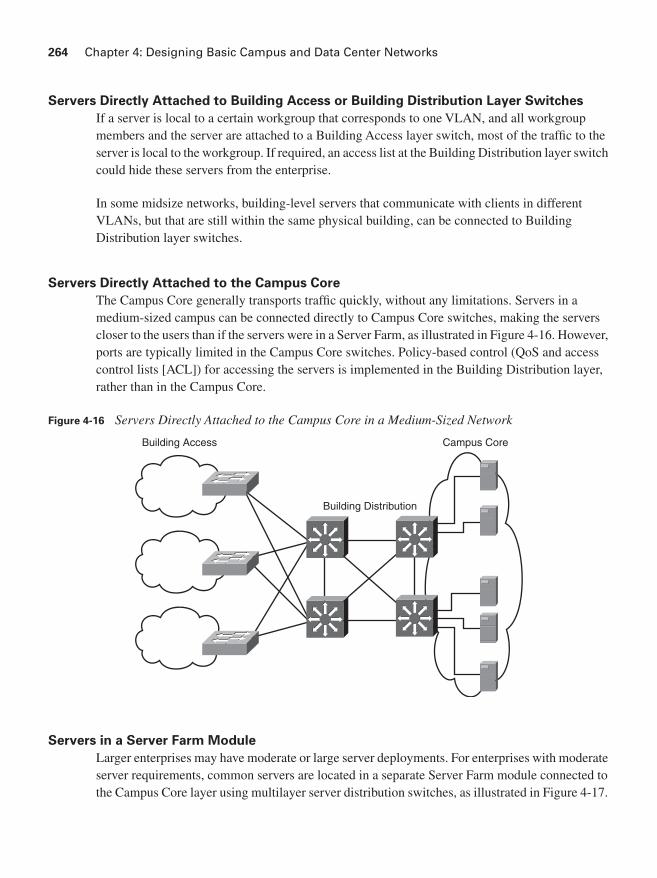
264 Chapter 4: Designing Basic Campus and Data Center Networks
Servers Directly Attached to Building Access or Building Distribution Layer Switches
If a server is local to a certain workgroup that corresponds to one VLAN, and all workgroup members and the server are attached to a Building Access layer switch, most of the traffic to the server is local to the workgroup. If required, an access list at the Building Distribution layer switch could hide these servers from the enterprise.
In some midsize networks, building-level servers that communicate with clients in different VLANs, but that are still within the same physical building, can be connected to Building Distribution layer switches.
Servers Directly Attached to the Campus Core
The Campus Core generally transports traffic quickly, without any limitations. Servers in a medium-sized campus can be connected directly to Campus Core switches, making the servers closer to the users than if the servers were in a Server Farm, as illustrated in Figure 4-16. However, ports are typically limited in the Campus Core switches. Policy-based control (QoS and access control lists [ACL]) for accessing the servers is implemented in the Building Distribution layer, rather than in the Campus Core.
Figure 4-16 Servers Directly Attached to the Campus Core in a Medium-Sized Network
Servers in a Server Farm Module
Larger enterprises may have moderate or large server deployments. For enterprises with moderate server requirements, common servers are located in a separate Server Farm module connected to the Campus Core layer using multilayer server distribution switches, as illustrated in Figure 4-17.
Building Access
Building Distribution
Campus Core

Enterprise Campus Design 265
Because of high traffic load, the servers are usually Gigabit Ethernet–attached to the Server Farm switches. Access lists at the Server Farm module’s multilayer distribution switches implement the controlled access to these servers. Redundant distribution switches in a Server Farm module and solutions such as the HSRP and GLBP provide fast failover. The Server Farm module distribution switches also keep all server-to-server traffic off the Campus Core.
Figure 4-17 Server Farm in a Large Network
Rather than being installed on only one server, modern applications are distributed among several servers. This approach improves application availability and responsiveness. Therefore, placing servers in a common group (in the Server Farm module) and using intelligent multilayer switches provide the applications and servers with the required scalability, availability, responsiveness, throughput, and security.
For a large enterprise with a significant number of servers, a separate data center, possibly in a remote location, is often implemented. Design considerations for an Enterprise Data Center are discussed in the later “Enterprise Data Center Design Considerations” section.
Campus Core
ServerDistribution
ServerAccess
Servers
Multilayer
Multilayer
Data LinkLayer
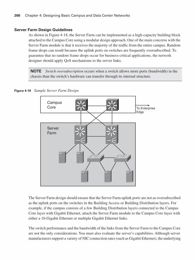
266 Chapter 4: Designing Basic Campus and Data Center Networks
Server Farm Design Guidelines
As shown in Figure 4-18, the Server Farm can be implemented as a high-capacity building block attached to the Campus Core using a modular design approach. One of the main concerns with the Server Farm module is that it receives the majority of the traffic from the entire campus. Random frame drops can result because the uplink ports on switches are frequently oversubscribed. To guarantee that no random frame drops occur for business-critical applications, the network designer should apply QoS mechanisms to the server links.
Figure 4-18 Sample Server Farm Design
The Server Farm design should ensure that the Server Farm uplink ports are not as oversubscribed as the uplink ports on the switches in the Building Access or Building Distribution layers. For example, if the campus consists of a few Building Distribution layers connected to the Campus Core layer with Gigabit Ethernet, attach the Server Farm module to the Campus Core layer with either a 10-Gigabit Ethernet or multiple Gigabit Ethernet links.
The switch performance and the bandwidth of the links from the Server Farm to the Campus Core are not the only considerations. You must also evaluate the server’s capabilities. Although server manufacturers support a variety of NIC connection rates (such as Gigabit Ethernet), the underlying
NOTE Switch oversubscription occurs when a switch allows more ports (bandwidth) in the chassis than the switch’s hardware can transfer through its internal structure.
To EnterpriseEdge
CampusCore
ServerFarm

Enterprise Campus Design 267
network operating system might not be able to transmit at the maximum line capacity. As such, oversubscription ratios can be raised, reducing the Server Farm’s overall cost.
Server Connectivity Options
Servers can be connected in several different ways. For example, a server can attach by one or two Fast Ethernet connections. If the server is dual-attached (dual-NIC redundancy), one interface can be active while the other is in hot standby. Installing multiple single-port NICs or multiport NICs in the servers extends dual homing past the Server Farm module switches to the server itself. Servers needing redundancy can be connected with dual-NIC homing in the access layer or a NIC that supports EtherChannel. With the dual-homing NIC, a VLAN or trunk is needed between the two access switches to support the single IP address on the two server links to two separate switches.
Within the Server Farm module, multiple VLANs can be used to create multiple policy domains as required. If one particular server has a unique access policy, a unique VLAN and subnet can be created for that server. If a group of servers has a common access policy, the entire group can be placed in a common VLAN and subnet. ACLs can be applied on the interfaces of the multilayer switches.
Several other solutions are available to improve server responsiveness and evenly distribute the load to them. For example, Figure 4-18 includes content switches that provide a robust front end for the Server Farm by performing functions such as load balancing of user requests across the Server Farm to achieve optimal performance, scalability, and content availability.
The Effect of Applications on Switch Performance
Server Farm design requires that you consider the average frequency at which packets are generated and the packets’ average size. These parameters are based on the enterprise applications’ traffic patterns and number of users of the applications.
Interactive applications, such as conferencing, tend to generate high packet rates with small packet sizes. In terms of application bandwidth, the packets-per-second limitation of the multilayer switches might be more critical than the throughput (in Mbps). In contrast, applications that involve large movements of data, such as file repositories, transmit a high percentage of full-length (large) packets. For these applications, uplink bandwidth and oversubscription ratios become key factors in the overall design. Actual switching capacities and bandwidths vary based on the mix of applications.
268 Chapter 4: Designing Basic Campus and Data Center Networks
Enterprise Data Center Design Considerations
This section describes general Enterprise Data Center design considerations and provides an overview of the general technologies and models used in an Enterprise Data Center.
The Enterprise Data CenterThis section describes technology and trends influencing the Enterprise Data Center. For large enterprises with a significant number of servers, a dedicated Enterprise Data Center provides employees, partners, and customers with access to data and resources to effectively work, collaborate, and interact. Historically, most Enterprise Data Centers grew rapidly as organizational requirements expanded. Applications were implemented as needed, often resulting in underutilized, isolated infrastructure silos. Each silo was designed based on the specific application being deployed, so a typical data center supported a broad assortment of operating systems, computing platforms, and storage systems, resulting in various application “islands” that were difficult to change or expand and expensive to manage, integrate, secure, and back up.
This server-centric data center model is evolving to a service-centric model, as illustrated in Figure 4-19. This evolution includes the following:
■ The deployment of virtual machine software, such as VMware and Xen, which breaks the one-to-one relationship between applications and the server hardware and operating system on which they run. Virtual machine software allows multiple applications to run on a single server, independent of each other and of the underlying operating system.
■ The removal of storage from the server, consolidating it in storage pools. Networked storage (such as storage area networks [SAN]) allows easier management, provisioning, improved utilization, and consistent recovery practices.
■ The creation of pools of one-way, two-way, or four-way servers that can be pooled and provisioned, on demand.
■ The consolidation of I/O resources so that the I/O can be pooled and provisioned on demand for connectivity to other servers, storage, and LAN pools.
NOTE VMware information is available at http://www.vmware.com/. Xen information is available at http://www.xensource.com/.
NOTE One-way servers have a single processor, two-way servers have two processors, and four-way servers have four processors.

Enterprise Data Center Design Considerations 269
Figure 4-19 Evolution from Server-Centric to Service-Centric Data Center
The resulting service-centric data center has pooled compute, storage, and I/O resources that are provisioned to support applications over the data center network. Because the network touches and can control all the components, the network can be used to integrate all the applications and services; network technology actively participates in the delivery of applications to end users.
The Cisco Enterprise Data Center Architecture FrameworkThe consolidation and virtualization of data center resources requires a highly scalable, resilient, secure data center network foundation.
As described in Chapter 2, “Applying a Methodology to Network Design,” the Cisco Service-Oriented Network Architecture (SONA) framework defines how enterprises can evolve toward intelligence in the network that optimizes applications, business processes, and resources. The Cisco Enterprise Data Center Architecture, based on SONA, provides organizations with a framework to address immediate data center demands for consolidation and business continuance while enabling emerging service-oriented architectures (SOA), virtualization, and on-demand computing technologies in the data center.
ApplicationSilos
ApplicationSilos
ApplicationSilos
Server-CentricMonolithicProprietaryCompute Silos
Aggregation ofStorage into SAN
Prevalence of1-RU and BladeServers withConsolidated I/O
Service-Centric Model“Pools” of Standardized ResourcesAssembled on Demand to Create
“Virtual Infrastructure”
DataCenter
Network
PooledStorage
Resources
Shared ApplicationServices
PooledCompute
Resources
User AccessNetwork

270 Chapter 4: Designing Basic Campus and Data Center Networks
The Cisco Enterprise Data Center Architecture, as illustrated in Figure 4-20, aligns data center resources with business applications and provides multiple resources to end users in an enterprise. The Cisco Enterprise Data Center Architecture has the following layers:
■ Networked Infrastructure layer: Meets all the bandwidth, latency, and protocol requirements for user-to-server, server-to-server, and server-to-storage connectivity and communications in a modular, hierarchical infrastructure.
■ Interactive Services layer: Provides the infrastructure services that ensure the fast and secure alignment of resources with application requirements and Cisco Application Networking Services that optimize application integration and the delivery of applications to end users.
Figure 4-20 Cisco Enterprise Data Center Network Architecture Framework
WAAS = Wide-Area Application Services; RDMA = Remote Data Memory Access; SFS = Server Fabric Switching; MDS = Multilayer Directors and Fabric Switches; ONS = Optical Networking Solutions; DWDM = Dense Wave Division Multiplexing; SONET = Synchronous Optical Network; SDH = Synchronous Digital Hierarchy; FCIP = Fiber Channel over IP
BusinessApplications
CollaborationApplications
Net
wor
ked
Infra
stru
ctur
eLa
yer
Application Networking Services
Infrastructure Management
Network Infrastructure Virtualization
Infrastructure Enhancing Services
Advanced Analytics and Decision Support
Inte
ract
ive
Ser
vice
sLa
yer
Ser
vice
sV
irtua
lizat
ion
Ser
vice
s M
anag
emen
t
Ada
ptiv
e M
anag
emen
t S
ervi
ces
WAAS, Application Acceleration,Optimization, Security and Server Offload
Firewalls, Intrusion Prevention,Security Agents
RDMA,Low Latency Clustering
Virtualization, Replication,Virtual Fabrics
ServerFabric
Storage Network
InfiniBandSwitching
SFS Family
ServerSwitching
ModularRackBlade
Catalyst Family
StorageSwitching
DirectorFabric
MDS Family
Data CenterInterconnect
DWDM,SONET,
SDH, FCIP
ONS Family
Traditional Architecture/Service-Oriented Architecture
Compute Network

Enterprise Data Center Design Considerations 271
The Cisco Enterprise Data Center Architecture provides a scalable foundation that allows data centers to host a variety of legacy and emerging systems and technologies, including the following:
■ N-tier applications: Secure network zones support two, three, or n-tier application environments with techniques that optimize application availability and server and storage utilization.
■ Web applications: Application acceleration and server optimization technologies provide improved scalability and delivery of web applications to end users, wherever they are.
■ Blade servers: As self-contained servers, blade servers, housed in a blade enclosure, have all the functional components required to be considered computers but have reduced physical components, so they require less space, power, and so forth. The Cisco Enterprise Data Center Architecture provides an intelligent network foundation using integrated Ethernet and InfiniBand switching technology that helps optimize blade server availability, security, and performance.
■ Clustering, high-performance computing and grid: The Cisco high-performance data, server, and storage switching solutions, whether based on Ethernet, InfiniBand, or Fiber Channel, enable the deployment of data- and I/O-intensive applications that make use of these distributed compute and storage architectures.
■ SOA and web service: The Cisco Enterprise Data Center Architecture facilitates the reliable, secure, and rapid deployment of an SOA by enabling dynamic deployment and scaling of secure infrastructures and by enhancing application integration with message-based services.
■ Mainframe computing: Cisco offers a comprehensive set of technologies supporting Systems Network Architecture (SNA), SNA-to-IP migration, fiber connection, and native IP mainframe services.
The Cisco Enterprise Data Center Architecture is supported by networking technologies and solutions that allow organizations to evolve their data center infrastructures through the following phases:
■ Consolidation: Integration of network, server, application, and storage services into a shared infrastructure enhances scalability and manageability while reducing cost and complexity.
■ Virtualization: Network-enabled virtualization of computing and storage resources and virtual network services increase utilization and adaptability while reducing overall costs.
■ Automation: Dynamic monitoring, provisioning, and orchestration of data center infrastructure resources resulting from changing loads, disruptions, or attacks increases overall IT agility while minimizing operational requirements.
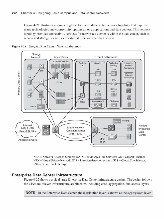
272 Chapter 4: Designing Basic Campus and Data Center Networks
Figure 4-21 illustrates a sample high-performance data center network topology that requires many technologies and connectivity options among applications and data centers. This network topology provides connectivity services for networked elements within the data center, such as servers and storage, as well as to external users or other data centers.
Figure 4-21 Sample Data Center Network Topology
NAS = Network Attached Storage; WAFS = Wide-Area File Services; GE = Gigabit Ethernet; VPN = Virtual Private Network; IDS = intrusion detection system; GSS = Global Site Selector; SSL = Secure Sockets Layer
Enterprise Data Center InfrastructureFigure 4-22 shows a typical large Enterprise Data Center infrastructure design. The design follows the Cisco multilayer infrastructure architecture, including core, aggregation, and access layers.
NOTE In the Enterprise Data Center, the distribution layer is known as the aggregation layer.
StorageNetwork Applications
Prim
ary
Dat
a C
ente
r
Clustered Servers
InfiniBand
SAN
NAS
Tape
WAFS
InternetMPLS VPN
IPsec/SSL VPN
Access Network
Metro NetworkOptical/Ethernet
ONS 15000
MDS9216
WAFS
Remoteor BackupDataCenter
Front End Network
ResilientIP
Security ApplicationDelivery
GE/10GE
IDS
Anomaly
Detect/Guard
ContentSwitch
SSL
GSS
File Cache
IntegratedBusiness
Applications
Application-Oriented
NetworkingDisk
VPN
Firewall
NAS

Enterprise Data Center Design Considerations 273
Figure 4-22 Sample Data Center Infrastructure
OSA = Open Systems Adapter
CampusCore
Data Center Core
Data CenterAggregation
ServicesModules
Data Center Access
Blade Chassiswith Pass-Through
Blade Chassiswith Integrated
Switch
Mainframewith OSA
Layer 3Access
Layer 2 Clusteringand NIC Teaming

274 Chapter 4: Designing Basic Campus and Data Center Networks
The data center infrastructure must provide port density and Layer 2 and Layer 3 connectivity for servers at the access layer, while supporting security services provided by ACLs, firewalls, and intrusion detection systems (IDS) at the data center aggregation layer. It must support Server Farm services, such as content switching, caching, and Secure Sockets Layer (SSL) offloading while integrating with multitier Server Farms, mainframes, and mainframe services (such as TN3270, load balancing, and SSL offloading). Network devices are often deployed in redundant pairs to avoid a single point of failure.
The following sections describe the three layers of the Enterprise Data Center infrastructure.
Data Center Access Layer
The Data Center Access layer provides Layer 2, Layer 3, and mainframe connectivity. The design of the Data Center Access layer varies depending on whether Layer 2 or Layer 3 access switches are used; it is typically built with high-performance, low-latency Layer 2 switches, allowing better sharing of service devices across multiple servers and allowing the use of Layer 2 clustering, which requires the servers to be Layer 2–adjacent. With Layer 2 access switches, the default gateway for the servers can be configured at the access or aggregation layer.
Servers can be single- or dual-attached; with dual-attached NICs in the servers, a VLAN or trunk is required between the two redundant access layer switches to support having a single IP address on the two server links to two separate switches. The default gateway is implemented at the access layer.
A mix of both Layer 2 and Layer 3 access switches using one rack unit (1RU) and modular platforms results in a flexible solution and allows application environments to be optimally positioned.
Data Center Aggregation Layer
The Data Center Aggregation (distribution) layer aggregates the uplinks from the access layer to the Data Center Core layer and is the critical point for control and application services.
Security and application service devices (such as load-balancing devices, SSL offloading devices, firewalls, and IDS devices) provide Layer 4 through Layer 7 services and are often deployed as a module in the aggregation layer. This highly flexible design takes advantage of economies of scale by lowering the total cost of ownership (TCO) and reducing complexity by reducing the number of components to configure and manage. Service devices deployed at the aggregation layer are shared among all the servers, whereas service devices deployed at the access layer benefit only the servers that are directly attached to the specific access switch.
Enterprise Data Center Design Considerations 275
Although Layer 2 at the aggregation (distribution) layer is tolerated for legacy designs, new designs should have Layer 2 only at the Data Center Access layer. With Layer 2 at the Data Center Aggregation layer, physical loops in the topology would have to be managed by STP; in this case, as for other designs, RPVST+ is a recommended best practice to ensure a logically loop-free topology over the physical topology.
The Data Center Aggregation layer typically provides Layer 3 connectivity from the data center to the core and maintains the connection and session state for redundancy. Depending on the requirements and the design, the boundary between Layer 2 and Layer 3 at the Data Center Aggregation layer can be in the multilayer switches, the firewalls, or the content-switching devices in the aggregation layer. Depending on the data center applications, the aggregation layer might also need to support a large STP processing load.
Data Center Core Layer
Implementing a Data Center Core layer is a best practice for large data centers. The following should be taken into consideration when determining whether a core is appropriate:
■ 10-Gigabit Ethernet density: Without a Data Center Core, will there be enough 10-Gigabit Ethernet ports on the Campus Core switch pair to support both the campus Building Distribution layer and the Data Center Aggregation layer?
■ Administrative domains and policies: Separate campus and data center cores help isolate the campus Building Distribution layers from Data Center Aggregation layers for troubleshooting, maintenance, administration, and implementation of policies (using QoS and ACLs).
■ Anticipation of future development: The impact that could result from implementing a separate Data Center Core layer at a later date might make it worthwhile to install it at the beginning.
The data center typically connects to the Campus Core using Layer 3 links. The data center network addresses are summarized into the Campus Core, and the Campus Core injects a default route into the data center network. Key Data Center Core layer characteristics include the following:
■ A distributed forwarding architecture
■ Low-latency switching
■ 10-Gigabit Ethernet scalability
■ Scalable IP multicast support

276 Chapter 4: Designing Basic Campus and Data Center Networks
Density and Scalability of Servers
Some scaling issues in the data center relate to the physical environment.
The most common access layer in enterprises today is based on the modular chassis Cisco Catalyst 6500 or 4500 Series switches. This topology has also proven to be a very scalable method of building Server Farms that provide high-density, high-speed uplinks and redundant power and processors. Although this approach has been very successful, it results in challenges when used in Enterprise Data Center environments. The typical Enterprise Data Center experiences high growth in the sheer number of servers; at the same time, server density has been improved with 1RU and blade server solutions. Three particular challenges result from this trend:
■ Cable bulk: Typically, three to four interfaces are connected on a server. With a higher density of servers per rack, cable routing and management can become quite difficult.
■ Power: The increased density of components in a rack is driving a need for a larger power feed to the rack. Many data centers do not have the power capacity at the server rows to support this increase.
■ Cooling: The number of cables lying under the raised floor and the cable bulk at the cabinet base entry is blocking the airflow required to cool equipment in the racks. At the same time, the servers in the rack require more cooling volume because of their higher density.
These challenges have forced customers to find alternative solutions by spacing cabinets, modifying cable routes, or other means, including not deploying high-density server solutions. Another way that customers seek to solve some of these problems is by using a rack-based switching solution. Using 1RU top-of-rack switches keeps the server interface cables in the cabinet, reducing the amount of cabling in the floor and thus reducing the cabling and cooling issues. Another option is to place Cisco Catalyst 6500 Series switches like bookends near the ends of the row of racks so that there are fewer switches to manage.
Summary
In this chapter you learned about campus and data center network design, with a focus on the following topics:
■ The effects of the characteristics of the following on the campus network design:
— Application: Including peer-peer, client–local server, client–Server Farm, and client–Enterprise Edge server
— Environment: Including the location of the network nodes, the distance between the nodes, and the transmission media used
— Infrastructure devices: Including Layer 2 or multilayer switching, convergence time, type of multilayer switching, IP multicast, QoS, and load sharing

Case Study: ACMC Hospital Network Campus Design 277
■ The design considerations and recommended practices for the Building Access layer, the Building Distribution layer, the Campus Core layer, the optional Edge Distribution module, and the Server Farm module.
■ Enterprise Data Center module design considerations, including an introduction to the general technologies and models used in Enterprise Data Center design.
References
For additional information, refer to the following resources:
■ Cisco Systems, Inc., Introduction to Gigabit Ethernet, http://www.cisco.com/en/US/tech/tk389/tk214/tech_brief09186a0080091a8a.html
■ Cisco Systems, Inc., Ethernet Introduction, http://www.cisco.com/en/US/tech/tk389/tk214/tsd_technology_support_protocol_home.html
■ Cisco Systems, Inc., SAFE Blueprint Introduction, http://www.cisco.com/go/safe
■ Cisco Systems, Inc., Designing a Campus Network for High Availability, http://www.cisco.com/application/pdf/en/us/guest/netsol/ns432/c649/cdccont_0900aecd801a8a2d.pdf
■ Cisco Systems, Inc., Enterprise Data Center: Introduction, http://www.cisco.com/en/US/netsol/ns340/ns394/ns224/networking_solutions_packages_list.html
■ Cisco Systems, Inc., Cisco Data Center Network Architecture and Solutions Overview, http://www.cisco.com/application/pdf/en/us/guest/netsol/ns377/c643/cdccont_0900aecd802c9a4f.pdf
■ Cisco Systems, Inc., Switches: Compare Products and Solutions, http://www.cisco.com/en/US/products/hw/switches/products_category_buyers_guide.html
■ Szigeti and Hattingh, End-to-End QoS Network Design: Quality of Service in LANs, WANs, and VPNs, Indianapolis, Cisco Press, 2004.
■ Cisco Systems, Inc., Spanning Tree Protocol: Introduction, http://www.cisco.com/en/US/tech/tk389/tk621/tsd_technology_support_protocol_home.html
Case Study: ACMC Hospital Network Campus Design
This case study is a continuation of the ACMC Hospital case study introduced in Chapter 2.

278 Chapter 4: Designing Basic Campus and Data Center Networks
Case Study General Instructions
Use the scenarios, information, and parameters provided at each task of the ongoing case study. If you encounter ambiguities, make reasonable assumptions and proceed. For all tasks, use the initial customer scenario and build on the solutions provided thus far. You can use any and all documentation, books, white papers, and so on.
In each step, you act as a network design consultant. Make creative proposals to accomplish the customer’s business needs. Justify your ideas when they differ from the provided solutions. Use any design strategies you feel are appropriate. The final goal of each case study is a paper solution.
Appendix A, “Answers to Review Questions and Case Studies,” provides a solution for each step based on assumptions made. There is no claim that the provided solution is the best or only solution. Your solution might be more appropriate for the assumptions you made. The provided solution helps you understand the author’s reasoning and allows you to compare and contrast your solution.
In this case study you create a high-level design for the Cisco Enterprise Campus Architecture of the ACMC Hospital network.
Case Study Additional InformationFigure 4-23 identifies the device counts throughout the ACMC campus.
Assume that each building needs as many spare ports as there are people. Each patient room or staff position has two jacks, and spare server ports should be provided to allow for migration of all servers to the Server Farm.
The hospital has 500 staff members and 1000 patients.
Each floor of the main buildings has about 75 people, except for the first floor of Main Building 1, which has only the Server Farm with 40 servers. Each floor of the Children’s Place has 60 people. Buildings A through D have 10 people each, buildings E through J have 20 people each, and buildings K through L have 40 each.
Assume that the hospital has structured cabling with plenty of MM fiber in the risers and plenty of fiber between buildings. If there is not enough fiber, either the hospital will have to install the fiber or the design will have to be modified for the existing cabling; produce an ideal design before making any adjustments.

Case Study: ACMC Hospital Network Campus Design 279
Figure 4-23 Case Study: ACMC Campus Device Counts
Case Study QuestionsComplete the following steps:
Step 1 Determine the location, quantity, and size of the required Campus Core switch or switches and what connections are required within the core and to the distribution layer.
Step 2 Determine the location of required Building Distribution layer switches or whether a collapsed core/distribution approach makes more sense. In a design with distribution layer switches, determine their location and size, how they connect to the Campus Core, and the use of VLANs versus Layer 3 switching.
12 Smaller Buildings1 or 2 Wiring Closetsper Building
4 Wiring Closets per Floor
Main Building 1
6 Floors +Server Farm
7 floors3 floors
40 Serversin ServerFarm + 30
4 Wiring Closets per Floor
Main Building 2
3 Wiring Closets per Floor
Children’s Place

280 Chapter 4: Designing Basic Campus and Data Center Networks
Step 3 Determine the location and size of the required Building Access layer switches, and complete Table 4-4.
Step 4 Determine how the Building Access layer switches will connect to the Building Distribution layer switches (or to the combined distribution/core switches).
Step 5 Determine how the Server Farm should be connected. If Server Farm access or distribution switches are used, determine how they will connect to each other and to the core.
Step 6 Does any other information need to be included in your final design?
Step 7 Determine appropriate Cisco switch models for each part of your campus design.
The following links might be helpful (note that these links were correct at the time this book was published):
• The Cisco switch main page at http://www.cisco.com/en/US/products/hw/switches/index.html
• The Cisco switch comparison page at http://www.cisco.com/en/US/products/hw/switches/products_category_buyers_guide.html
• The Cisco Product Quick Reference Guide at http://www.cisco.com/warp/public/752/qrg/index.shtml
• The Cisco Catalyst Switch Solution Finder at http://www.cisco.com/en/US/partner/products/hw/switches/products_promotion0900aecd8050364f.html
Table 4-4 Building Access Layer Port Counts by Location
Location Port Counts Port Counts with Spares Comments
Main building 1, per floor
Main building Server Farm
Main building 2, per floor
Children’s Place, per floor
Buildings A–D
Buildings E–J
Buildings K–L

Case Study: ACMC Hospital Network Campus Design 281
Step 8 (Optional) Use the Cisco Dynamic Configuration Tool to configure one or more of the switches in your design. The Cisco Dynamic Configuration Tool is available at the following link: http://www.cisco.com/en/US/ordering/or13/or8/ordering_ordering_help_dynamic_configuration_tool_launch.html. (Note that a valid username and password on www.cisco.com are required to access this tool.)
Figure 4-24 displays a screen shot showing the options available for a Catalyst 6506 switch.
Figure 4-24 Cisco Dynamic Configuration Tool Screen Output
Selecting the options for devices is easier and faster if you use only a few switch models repeatedly in your design, possibly with different numbers of blades in them.
NOTE There are not many options for the smaller switches in the Cisco Dynamic Configuration Tool.

282 Chapter 4: Designing Basic Campus and Data Center Networks
Step 9 (Optional) Develop a bill of materials (BOM) listing switch models, numbers, prices, and total price.
Creating a BOM can be time-consuming; you might want to use the Sample Price List provided in Table 4-5 for this exercise. Note that the prices shown in this table are not actual equipment prices; they are loosely derived from Cisco list prices at the time of publication and are provided for your convenience.
Table 4-5 Case Study: Sample Price List
Category Part Number Description
Fictional
Price
Port Transceiver Modules
Generic SFP $400
Generic GBIC $400
Generic LR Xenpack $4000
Cisco Catalyst 2960 Series Workgroup Switches
WS-C2960-24TC-L Catalyst 2960 24 10/100 + 2T/SFP LAN Base Image
$2500
WS-C2960-24TT-L Catalyst 2960 24 10/100 + 2 1000BT LAN Base Image
$1300
WS-C2960-48TC-L Catalyst 2960 48 10/100 + 2T/SFP LAN Base Image
$4500
WS-C2960-48TT-L Catalyst 2960 48 10/100 Ports + 2 1000BT LAN Base Image
$2500
WS-C2960G-24TC-L Catalyst 2960 24 10/100/1000, 4T/SFP LAN Base Image
$3300
WS-C2960G-48TC-L Catalyst 2960 48 10/100/1000, 4T/SFP LAN Base Image
$6000
Cisco Catalyst 3560 Series
WS-C3560G-48TS-S Catalyst 3560 48 10/100/1000T + 4 SFP Standard Image
$8000
WS-C3560G-24TS-S Catalyst 3560 24 10/100/1000T + 4 SFP Standard Image
$4800
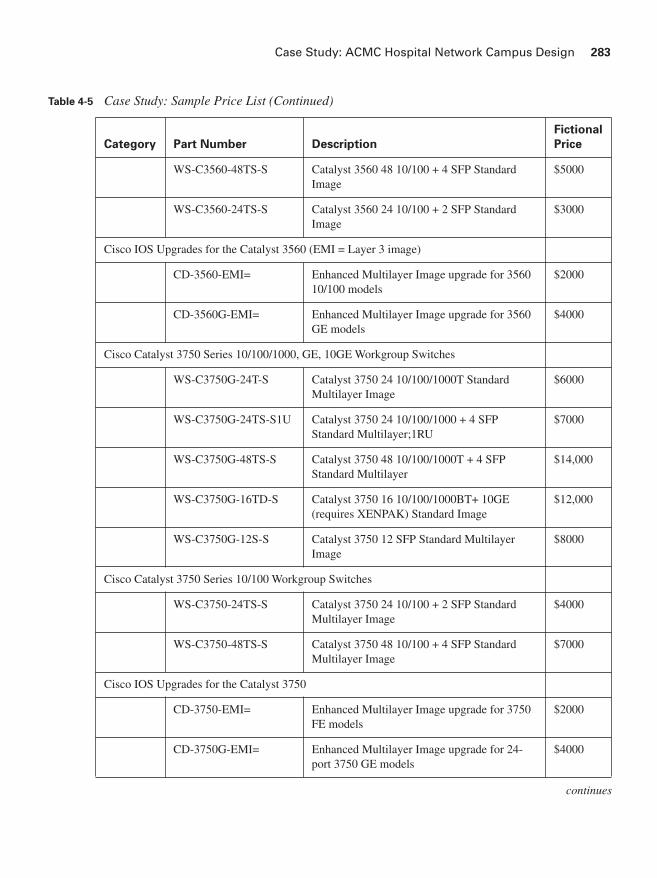
Case Study: ACMC Hospital Network Campus Design 283
Category Part Number Description
Fictional
Price
WS-C3560-48TS-S Catalyst 3560 48 10/100 + 4 SFP Standard Image
$5000
WS-C3560-24TS-S Catalyst 3560 24 10/100 + 2 SFP Standard Image
$3000
Cisco IOS Upgrades for the Catalyst 3560 (EMI = Layer 3 image)
CD-3560-EMI= Enhanced Multilayer Image upgrade for 3560 10/100 models
$2000
CD-3560G-EMI= Enhanced Multilayer Image upgrade for 3560 GE models
$4000
Cisco Catalyst 3750 Series 10/100/1000, GE, 10GE Workgroup Switches
WS-C3750G-24T-S Catalyst 3750 24 10/100/1000T Standard Multilayer Image
$6000
WS-C3750G-24TS-S1U Catalyst 3750 24 10/100/1000 + 4 SFP Standard Multilayer;1RU
$7000
WS-C3750G-48TS-S Catalyst 3750 48 10/100/1000T + 4 SFP Standard Multilayer
$14,000
WS-C3750G-16TD-S Catalyst 3750 16 10/100/1000BT+ 10GE (requires XENPAK) Standard Image
$12,000
WS-C3750G-12S-S Catalyst 3750 12 SFP Standard Multilayer Image
$8000
Cisco Catalyst 3750 Series 10/100 Workgroup Switches
WS-C3750-24TS-S Catalyst 3750 24 10/100 + 2 SFP Standard Multilayer Image
$4000
WS-C3750-48TS-S Catalyst 3750 48 10/100 + 4 SFP Standard Multilayer Image
$7000
Cisco IOS Upgrades for the Catalyst 3750
CD-3750-EMI= Enhanced Multilayer Image upgrade for 3750 FE models
$2000
CD-3750G-EMI= Enhanced Multilayer Image upgrade for 24-port 3750 GE models
$4000
Table 4-5 Case Study: Sample Price List (Continued)
continues

284 Chapter 4: Designing Basic Campus and Data Center Networks
Category Part Number Description
Fictional
Price
CD-3750G-48EMI= Enhanced Multilayer Image upgrade for 48-port 3750 GE models
$8000
3750-AISK9-LIC-B= Advanced IP Services upgrade for 3750 FE models running SMI
$5000
3750G-AISK9-LIC-B= Advanced IP Services upgrade for 3750 GE models running SMI
$7000
3750G48-AISK9LC-B= Advanced IP Services upgrade for 3750G-48 models running SMI
$11,000
Cisco Catalyst 4948 Switches
WS-C4948-S Catalyst 4948, IPB software, 48-port 10/100/1000+4 SFP, 1 AC power supply
$10,500
WS-C4948-E Catalyst 4948, ES software, 48-port 10/100/1000+4 SFP, 1 AC power supply
$14,500
WS-C4948-10GE-S Catalyst 4948, IPB software, 48*10/100/1000+2*10GE(X2), 1 AC power supply
$17,500
WS-C4948-10GE-E Catalyst 4948, ES Image, 48*10/100/1000+2*10GE(X2), 1 AC power supply
$21,500
Cisco Catalyst 4948 Software
S49L3K9-12220EWA Cisco Catalyst 4948 IOS Standard Layer 3 3DES (RIP, St. Routes, IPX, AT)
$0
S49L3EK9-12220EWA Cisco Catalyst 4948 IOS Enhanced Layer 3 3DES (OSPF, EIGRP, IS-IS, BGP)
$4000
S49ESK9-12225SG Cisco Catalyst 4900 IOS Enterprise Services SSH
$4000
Cisco Catalyst 4500—Chassis
WS-C4510R Catalyst 4500 Chassis (10-slot), fan, no power supply, Redundant Supervisor Capable
$12,500
WS-C4507R Catalyst 4500 Chassis (7-slot), fan, no power supply, Redundant Supervisor Capable
$10,000
WS-C4506 Catalyst 4500 Chassis (6-slot), fan, no power supply
$5000
Table 4-5 Case Study: Sample Price List (Continued)

Case Study: ACMC Hospital Network Campus Design 285
Category Part Number Description
Fictional
Price
WS-C4503 Catalyst 4500 Chassis (3-slot),fan, no power supply
$1000
WS-C4506-S2+96 Catalyst 4506 Bundle, 1x 1000AC, 1x S2+, 2x WS-X4148-RJ
$16,800
WS-C4503-S2+48 Catalyst 4503 Bundle, 1x 1000AC, 1x S2+, 1x WS-X4148-RJ
$10,000
Cisco Catalyst 4500 Non-PoE Power Supplies
PWR-C45-1400AC Catalyst 4500 1400W AC Power Supply (Data Only)
$1500
PWR-C45-1000AC Catalyst 4500 1000W AC Power Supply (Data Only)
$1000
Cisco Catalyst 4500 Supervisor Engines
WS-X4516-10GE Catalyst 4500 Supervisor V-10GE, 2x10GE (X2) and 4x1GE (SFP)
$20,000
WS-X4516-10GE/2 Catalyst 45xxR Supervisor V-10GE, 2x10GE (X2) or 4x1GE (SFP)
$20,000
WS-X4516 Catalyst 4500 Supervisor V (2 GE), Console (RJ-45)
$16,500
WS-X4515 Catalyst 4500 Supervisor IV (2 GE), Console (RJ-45)
$12,000
WS-X4013+10GE Catalyst 4500 Supervisor II+10GE, 2x10GE (X2), and 4x1GE (SFP)
$12,000
WS-X4013+ Catalyst 4500 Supervisor II-Plus (IOS), 2GE, Console (RJ-45)
$6000
WS-X4013+TS Catalyst 4503 Supervisor II-Plus-TS, 12 10/100/1000 PoE+8 SFP slots
$6000
Cisco Catalyst 4500 10/100 Linecards
WS-X4148-RJ Catalyst 4500 10/100 Auto Module, 48-Ports (RJ-45)
$4500
WS-X4124-RJ45 Catalyst 4500 10/100 Module, 24-Ports (RJ-45) $2500
Table 4-5 Case Study: Sample Price List (Continued)
continues
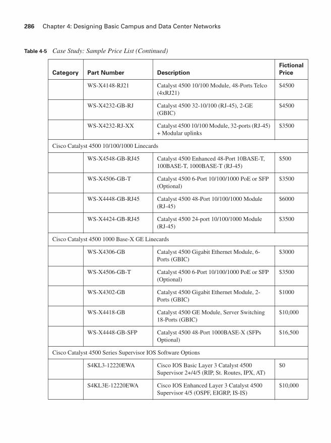
286 Chapter 4: Designing Basic Campus and Data Center Networks
Category Part Number Description
Fictional
Price
WS-X4148-RJ21 Catalyst 4500 10/100 Module, 48-Ports Telco (4xRJ21)
$4500
WS-X4232-GB-RJ Catalyst 4500 32-10/100 (RJ-45), 2-GE (GBIC)
$4500
WS-X4232-RJ-XX Catalyst 4500 10/100 Module, 32-ports (RJ-45) + Modular uplinks
$3500
Cisco Catalyst 4500 10/100/1000 Linecards
WS-X4548-GB-RJ45 Catalyst 4500 Enhanced 48-Port 10BASE-T, 100BASE-T, 1000BASE-T (RJ-45)
$500
WS-X4506-GB-T Catalyst 4500 6-Port 10/100/1000 PoE or SFP (Optional)
$3500
WS-X4448-GB-RJ45 Catalyst 4500 48-Port 10/100/1000 Module (RJ-45)
$6000
WS-X4424-GB-RJ45 Catalyst 4500 24-port 10/100/1000 Module (RJ-45)
$3500
Cisco Catalyst 4500 1000 Base-X GE Linecards
WS-X4306-GB Catalyst 4500 Gigabit Ethernet Module, 6-Ports (GBIC)
$3000
WS-X4506-GB-T Catalyst 4500 6-Port 10/100/1000 PoE or SFP (Optional)
$3500
WS-X4302-GB Catalyst 4500 Gigabit Ethernet Module, 2-Ports (GBIC)
$1000
WS-X4418-GB Catalyst 4500 GE Module, Server Switching 18-Ports (GBIC)
$10,000
WS-X4448-GB-SFP Catalyst 4500 48-Port 1000BASE-X (SFPs Optional)
$16,500
Cisco Catalyst 4500 Series Supervisor IOS Software Options
S4KL3-12220EWA Cisco IOS Basic Layer 3 Catalyst 4500 Supervisor 2+/4/5 (RIP, St. Routes, IPX, AT)
$0
S4KL3E-12220EWA Cisco IOS Enhanced Layer 3 Catalyst 4500 Supervisor 4/5 (OSPF, EIGRP, IS-IS)
$10,000
Table 4-5 Case Study: Sample Price List (Continued)

Case Study: ACMC Hospital Network Campus Design 287
Category Part Number Description
Fictional
Price
Cisco Catalyst 6500 Series Supervisor 32-GE Bundles—Top Sellers
WS-C6503E-S32-GE Cisco Catalyst 6503E, WS-SUP32-GE-3B, Fan Tray (requires power supply)
$13,000
WS-C6504E-S32-GE 6504-E Chassis + Fan Tray + Supervisor 32-GE
$13,000
WS-C6506E-S32-GE Cisco Catalyst 6506E, WS-Supervisor 32-GE-3B, Fan Tray (requires power supply)
$16,000
WS-C6509E-S32-GE Cisco Catalyst 6509E, WS-Supervisor32-GE-3B, Fan Tray (requires power supply)
$20,000
WS-C6513-S32-GE Cisco Catalyst 6513, WS-Supervisor 32-GE-3B, Fan Tray (requires power supply)
$26,000
Cisco Catalyst 6500 Series Supervisor 32-10GE Bundles—Top Sellers
WS-C6503E-S32-10GE Cat6503E chassis, WS-Supervisor 32-10GE-3B, Fan Tray (requires power supply)
$23,000
WS-C6504E-S32-10GE 6504-E Chassis + Fan Tray + Supervisor 32-10GE
$23,000
WS-C6506E-S32-10GE Cat6506E chassis, WS-Supervisor 32-10GE-3B, Fan Tray (requires power supply)
$26,000
WS-C6509E-S32-10GE Cat6509E chassis, WS-Supervisor 32-10GE-3B, Fan Tray (requires power supply)
$30,000
Cisco Catalyst 6500 Series AC Power Supplies—Top Sellers
PWR-2700-AC/4 2700W AC power supply for Cisco 7604/6504-E
$3000
WS-CAC-3000W Catalyst 6500 3000W AC power supply $3000
WS-CAC-6000W Cat6500 6000W AC power supply $5000
Cisco Catalyst 6500 Series 10 Gigabit Ethernet—Top Sellers
WS-X6704-10GE Cat6500 4-port 10 Gigabit Ethernet Module (requires XENPAKs)
$20,000
S-67-10GE-C2 Cat6500, 1x6704-10 GE, 1xWS-F6700-DFC3B, 2xXENPAK-10GB-SR=
$33,500
Table 4-5 Case Study: Sample Price List (Continued)
continues
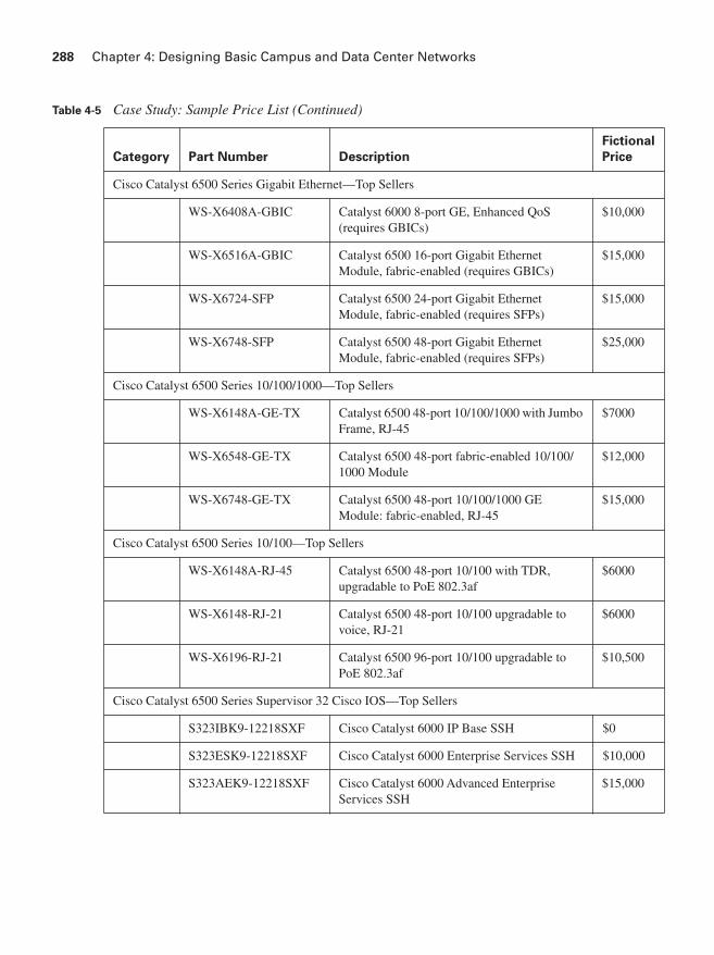
288 Chapter 4: Designing Basic Campus and Data Center Networks
Category Part Number Description
Fictional
Price
Cisco Catalyst 6500 Series Gigabit Ethernet—Top Sellers
WS-X6408A-GBIC Catalyst 6000 8-port GE, Enhanced QoS (requires GBICs)
$10,000
WS-X6516A-GBIC Catalyst 6500 16-port Gigabit Ethernet Module, fabric-enabled (requires GBICs)
$15,000
WS-X6724-SFP Catalyst 6500 24-port Gigabit Ethernet Module, fabric-enabled (requires SFPs)
$15,000
WS-X6748-SFP Catalyst 6500 48-port Gigabit Ethernet Module, fabric-enabled (requires SFPs)
$25,000
Cisco Catalyst 6500 Series 10/100/1000—Top Sellers
WS-X6148A-GE-TX Catalyst 6500 48-port 10/100/1000 with Jumbo Frame, RJ-45
$7000
WS-X6548-GE-TX Catalyst 6500 48-port fabric-enabled 10/100/1000 Module
$12,000
WS-X6748-GE-TX Catalyst 6500 48-port 10/100/1000 GE Module: fabric-enabled, RJ-45
$15,000
Cisco Catalyst 6500 Series 10/100—Top Sellers
WS-X6148A-RJ-45 Catalyst 6500 48-port 10/100 with TDR, upgradable to PoE 802.3af
$6000
WS-X6148-RJ-21 Catalyst 6500 48-port 10/100 upgradable to voice, RJ-21
$6000
WS-X6196-RJ-21 Catalyst 6500 96-port 10/100 upgradable to PoE 802.3af
$10,500
Cisco Catalyst 6500 Series Supervisor 32 Cisco IOS—Top Sellers
S323IBK9-12218SXF Cisco Catalyst 6000 IP Base SSH $0
S323ESK9-12218SXF Cisco Catalyst 6000 Enterprise Services SSH $10,000
S323AEK9-12218SXF Cisco Catalyst 6000 Advanced Enterprise Services SSH
$15,000
Table 4-5 Case Study: Sample Price List (Continued)

Review Questions 289
Review Questions
Answer the following questions, and then refer to Appendix A for the answers.
1. What characteristics must you consider when designing a campus network?
2. What are the most important network requirements for client–Enterprise Edge application communication?
3. List examples of applications that would be appropriate to reside in a Server Farm.
4. A company keeps all its servers and workstations within one building. What geographic design structure should you choose?
5. Describe how interbuilding and distant remote network geographic structures are different.
6. What is the difference between the 80/20 rule and the 20/80 rule?
7. What type of cable would you recommend for connecting two switches that are 115 m apart?
8. Compare the range and bandwidth specifications of copper twisted pair, MM fiber, SM fiber, and wireless.
9. Fill in Table 4-6 for the IEEE 802.11 wireless standards.
10. What is the difference between data link layer and multilayer switching?
11. What is a network flow?
12. What applications might require the network to handle multicast traffic?
13. A company is using video on demand, which uses IP multicast as part of its distance-learning program. The routers are configured for IP multicast. Taking into account that the majority of the LAN switches are Layer 2 switches, which protocol should be enabled on the LAN switches to reduce flooding?
NOTE For other options not listed in Table 4-5, assume a 5 to 10 percent upgrade charge from components shown. For example, if PoE is desired on upgradeable modules, include an upgrade charge of 10 percent per module.
Table 4-6 IEEE 802.11 Wireless Standards
Standard Frequency Band Maximum Bandwidth
802.11a
802.11b
802.11g

290 Chapter 4: Designing Basic Campus and Data Center Networks
14. What is PIM?
15. Why might QoS mechanisms be required on a LAN switch?
16. Which parts of the Enterprise Campus typically have both high availability and high performance requirements?
17. A link between the Building Distribution and Campus Core is oversubscribed, but it carries mission-critical data along with Internet traffic. How would you ensure that the mission-critical applications are not adversely affected by the bandwidth limitations?
18. A corporate network is spread over four floors. Each floor has a Layer 2 switch and more than one VLAN. One connection from each floor leads to the basement, where all WAN connections are terminated and all servers are located. Traffic between VLANs is essential. What type of device should be used in the basement?
19. What are the recommended best practices related to managing VLANs and STP in the Building Access layer?
20. What functions does the Building Distribution layer provide?
21. As a recommended practice, when should a dedicated Campus Core layer be deployed?
22. An organization requires a highly available core network and uses IP telephony for all its voice communication, both internal and external. Which devices and topology would you recommend for the Campus Core design?
23. What is the function of the Edge Distribution module?
24. A company has mission-critical applications hosted on common servers that are accessible to selected employees throughout the company’s multiple buildings. Where and how would you recommend that these servers be placed within the network?
25. Describe how the Enterprise Data Center has evolved to a service-centric model from a server-centric model.
26. An organization evolves its data center infrastructure; put the following phases of evolution in the correct order:
■ Virtualization
■ Consolidation
■ Automation
27. What is the purpose of the Data Center aggregation layer?
28. When determining whether to implement a Core layer within a Data Center design, what factors should you consider?

This page intentionally left blank