thin lenses - default page for overall website 8 thin lenses 8.1 objectives • measure the focal...
TRANSCRIPT

Experiment 8
Thin Lenses
8.1 Objectives
• Measure the focal length of a converging lens.
• Measure the focal length of a diverging lens.
• Investigate the relationship between power and focal length.
8.2 Introduction
Lenses are devices that manipulate the path of light rays, allowing us tobend the rays toward or away from each other. Our eyes have evolvednaturally to perform this task and enhance our vision, while humans havefigured out how to fashion lenses out of glass and plastic, giving us view-ing access to previously inaccessible phenomena from galaxies to bacteria.The physics of lenses is also used to detect the presence of “dark matter”surrounding galaxies (gravitational lensing), as well as to direct beams ofatomic nuclei in particle accelerators like in the Cyclotron Building acrossthe courtyard. However, the first step is to get some experience with thinlenses (thin enough so that we can ignore their thickness) where the mathis somewhat more tractable than with more exotic lenses.
149
8. Thin Lenses
8.3 Key Concepts
As always, you can find a summary online at Hyperphysics1. Look forkeywords: lenses, thin lenses, images, focal length, real images, virtualimages and magnification.
8.4 Theory
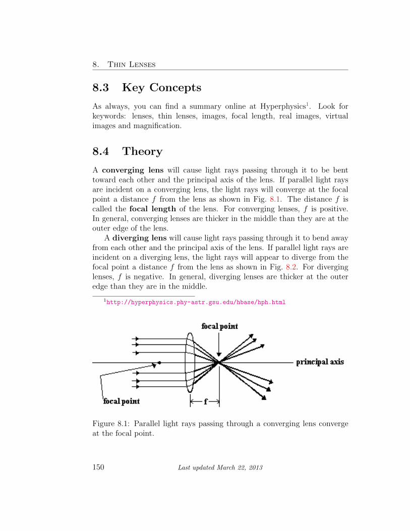
A converging lens will cause light rays passing through it to be benttoward each other and the principal axis of the lens. If parallel light raysare incident on a converging lens, the light rays will converge at the focalpoint a distance f from the lens as shown in Fig. 8.1. The distance f iscalled the focal length of the lens. For converging lenses, f is positive.In general, converging lenses are thicker in the middle than they are at theouter edge of the lens.
A diverging lens will cause light rays passing through it to bend awayfrom each other and the principal axis of the lens. If parallel light rays areincident on a diverging lens, the light rays will appear to diverge from thefocal point a distance f from the lens as shown in Fig. 8.2. For diverginglenses, f is negative. In general, diverging lenses are thicker at the outeredge than they are in the middle.
1http://hyperphysics.phy-astr.gsu.edu/hbase/hph.html
Figure 8.1: Parallel light rays passing through a converging lens convergeat the focal point.
150 Last updated March 22, 2013

8.4. Theory
Figure 8.2: Parallel light rays passing through a diverging lens spread out.The light rays appear to diverge from the focal point on the front side ofthe lens.
Ray diagrams can be a useful tool for analyzing the behavior of lightrays passing through thin lenses. Here are some rules for drawing light raysin ray diagrams.
1. A light ray approaching the lens parallel to the principle axis willpass through the focal point on the opposite side of the lens for aconverging lens or appear to diverge from the focal point on the sameside of the lens for a diverging lens (see Fig. 8.1 and Fig. 8.2).
2. A light ray passing through the center of the lens will not changedirection as it passes through the lens.
3. A light ray passing through the focal point will be parallel to theprincipal axis when it leaves the lens.
Consider the ray diagrams shown in Figs. 8.3 and 8.4. For clarity, onlyrays 1 and 2 (explained above) are shown. Note in these figures that h is theheight of the object, h� is the height of the image, p is the object distance(measured from the lens) and q is the image distance (measured from thelens). An image is formed where the rays intersect.
There are two types of images: real and virtual. Real images occurwhen the light rays actually converge on a point and form an image. These
Last updated March 22, 2013 151

8. Thin Lenses
Figure 8.3: Real image formed by a converging lens.
Figure 8.4: Virtual image formed by a diverging lens.
152 Last updated March 22, 2013

8.4. Theory
types of images can be displayed on a screen. A virtual image is formedwhen the light rays appear to diverge from a point. Because the rays donot actually diverge from this point (that is, pass through the point), theycannot be displayed on a screen. Converging lenses can form both real andvirtual images. A diverging lens by itself can only form a virtual image. Inthe last part of this lab, you will use an image formed by a converging lensas the object for a diverging lens. The resulting image from this two-lenssystem can be real.
Sign conventions for lenses
When doing calculations for thin lenses you will need to follow the signconventions listed below. Note that the front side of the lens is definedas the side of the lens from which the light is traveling (in the precedingdiagrams it is the left-hand side of the lens). The back side of the lens isdefined as the side to which the light is traveling (in the preceding diagramsit is the right-hand side of the lens).
• The object distance, p, is positive when the object is on the front sideof the lens.
• The object distance, p, is negative when it is on the back side of thelens.
• The image distance, q, is positive when the image is on the back sideof the lens.
• The image distance, q, is negative when it is on the front side of thelens.
• The object height, h, is always positive.
• Image height, h�, is negative when the image is inverted (compared tothe object).
• The image height, h�, is positive when the image is upright (i.e. hasthe same orientation as the object).
For systems with a single optical element (i.e. just one lens), a real imagewill always have a negative image height (because the image is inverted)and a positive image distance. In contrast, a virtual image will always have
Last updated March 22, 2013 153

8. Thin Lenses
a positive image height (because the image is upright) and a negative imagedistance.
Magnification
The intuitive definition of magnification is how much bigger (or smaller) animage is compared to the original object.
M =image height
object height=
h�
h(8.1)
Notice that for a real image formed by a single lens2 the magnification isnegative; the negative sign tells you that the image is inverted.
Referring back to Fig. 8.3, we can use the geometric notion of similartriangles to find an alternate expression for magnification in terms of theobject and image distances, p and q.
h
p= −h
�
q
Rearranging this expression we find:
−q
p=
h�
h
The right-hand side is the same as in Eq. 8.1, therefore:
M = −q
p(8.2)
Notice that you need the minus sign in Eq. 8.2 to get the same answeras Eq. 8.1. For example, both the image and object distances, p and q, fora real (inverted) image from a converging lens are positive, but because wedefined magnification to be negative for inverted images you need a minussign in Eq. 8.2.
2The single lens must be a converging lens, as a diverging lens cannot make a realimage by itself.
154 Last updated March 22, 2013

8.4. Theory
Focal Length
The focal length f of a thin lens is related to the object distance p andimage distance q by the following expression:
1
f=
1
p+
1
q(8.3)
If we rearrange Eq. 8.3 we obtain:
1
q= −1
p+
1
f(8.4)
Notice Eq. 8.4 has the same form as the equation of a straight line,
y = mx + b. With1
qplaying the role of y,
1
pplaying the role of x and
1
f
as the intercept. What is the slope m in Eq. 8.4? (You will need this forquestion #2.)
If you wear corrective lenses you may have noticed that your eyeglassprescription has units of Diopters (D). This is because your prescriptiontells you the refractive power of your lens, which is a measure of its abilityto bend light rays. The power P is related to the focal length f by
P =1
f(8.5)
where the focal length is in meters; so a Diopter D is equivalent to meter−1.(Be careful with units and make sure to convert centimeters to meters be-fore calculating the power of a lens.) The power will be positive or negativedepending on whether you are farsighted (hyperopic) or nearsighted (my-opic). If you are farsighted (i.e. you can only see things that are far away)your prescription will have a positive power and focal length which tellsthe lens maker to use a converging lens. If you are nearsighted (i.e. youcan only see things that are nearby) your prescription will have a negativepower and focal length which tells the lens maker to use a diverging lens.For example, if your prescription is -4.0 D then you are nearsighted andneed diverging lenses with a focal length of 0.25 m = 25 cm. Alternatively,if your prescription is +1.0 D then you are farsighted and need converginglenses with a focal length of 1 m.
Last updated March 22, 2013 155

8. Thin Lenses
8.5 In today’s lab
First we’ll become accustomed to forming images using a converging lensand use object and image distances to determine its focal length. Then wewill form an image with a two lens system, using a converging and diverginglens, to determine the focal length of a diverging lens.
Measuring the focal length of a converging lens
In this experiment, you will measure a series of object distances and corre-sponding image distances for a converging lens and calculate its focal length.
You will do this by constructing a graph of1
qvs
1
pand using Eq. 8.4 to find
the focal length.
Measuring the focal length of a diverging lens
To measure the focal length of a diverging lens, we will first use a converginglens to create a real image. This real image will then become the object forthe diverging lens.3 We will place the diverging lens such that the imageformed by the converging lens is on the diverging lens’s back side as shown inFig. 8.5. Remember from the earlier section on “Sign conventions for lenses”the object distance p is defined to be negative if it is on the back side of thelens. This two-lens system, one converging and one diverging lens, allowsus to make a real image that can be viewed on a screen. (Remember thata diverging lens alone can only make a virtual image which is not viewableon a screen.) Using the object and image distances from the diverging lensand Eq. 8.3, the focal length of the diverging lens can be calculated.
3For any multi-lens system (involving 2 or more lenses) understanding the entiresystem only involves following the simple rule that the image from the first lens acts asthe object for the second lens. If there are > 2 lenses then the image from the secondlens acts as the object for the third lens, etc.
156 Last updated March 22, 2013

8.6. Equipment
Figure 8.5: A converging lens forms a real image then a diverging lens isadded to form a new real image which can be viewed on a screen.
8.6 Equipment
The experimental setup we will use to measure the focal length of a con-verging lens is shown in Fig. 8.6 and the experimental setup we will use tomeasure the focal length of a diverging lens is shown in Fig. 8.7.
• Optics bench
• LED object (shown in Fig. 8.8)
• Converging lens
• Diverging lens
• Screen
Last updated March 22, 2013 157

8. Thin Lenses
Figure 8.6: Optics bench with an object, a converging lens and a screen.
Figure 8.7: Optics bench with an object, a converging lens, a diverging lensand a screen.
158 Last updated March 22, 2013

8.7. Procedure
8.7 Procedure
Focal length of a converging lens
1. Measure the height of the object as shown in Fig. 8.8 and record it inthe thin lenses Excel spreadsheet.
2. Place a 25.0 cm focal length converging lens at a distance of p =60.0 cm away from the object. Then adjust the screen until a clearimage is formed. Assign a reasonable uncertainty to your object dis-tance p and record it in your Excel spreadsheet. You should notice asyou move the screen back and forth that there is a range over whichthe image appears clear. You should place the screen in the center ofthis range and use half of the range as your uncertainty in the imagedistance q. (Is this distance large compared to your uncertainty inreading the meter stick?) Measure the image distance q and record itand its uncertainty in your spreadsheet. Measure the height of yourimage as shown in Fig. 8.9 and record it plus a reasonable estimateof its uncertainty in your Excel spreadsheet.
3. Repeat step 2 for object distances of 55 cm, 50 cm, 45 cm and 40 cm.
4. Have Excel calculate the magnification (M1) for each of your mea-surements using Eq. 8.1. Also, calculate the uncertainty4 using:
δM1 = |M1|���δh
h
���+���δh
�
h�
���
5. Have Excel calculate the magnification (M2) for each of your mea-surements using Eq. 8.2. Also, calculate the uncertainty using
δM2 = |M2|���δp
p
���+���δq
q
���
6. Have Excel calculate1
p,1
q, and δ
1
q
=
1
q
δq
q=
δq
q2. Import these
data columns into Kaleidagraph and construct a graph of1
qvs.
1
p.
Include vertical error bars and have Kaleidagraph fit it with a best-fitline with the relevant uncertainties included.
4The straight vertical lines “|” mean “absolute value of” and are needed because thesize of an uncertainty is never negative. The Excel command for absolute value of anumber is ABS(number).
Last updated March 22, 2013 159

8. Thin Lenses
Figure 8.8: A picture of the LED number 4 that you will be using as yourobject showing how to measure its height.
Figure 8.9: A picture of what your image should look like on the screen,notice that it is inverted (i.e. real), showing how to measure the imageheight.
160 Last updated March 22, 2013

8.7. Procedure
Focal length of a diverging lens
1. Return the converging lens to a distance of 40.0 cm from the objectand adjust the screen until a clear image is formed.
2. Place a diverging lens having a focal length of −30.0 cm at a distanceof 10.0 cm from the screen (i.e. the diverging lens should be betweenthe screen and the converging lens). By placing it in this location,your object distance for the diverging lens is −10.0 cm. Assign areasonable uncertainty to this distance (remember you should includethe uncertainty in finding the image formed by the converging lens).
3. Adjust the screen until a clear image is formed. Measure the imagedistance q. (Note this is the distance between the diverging lens andthe screen.) Use Eq. 8.3 to calculate the focal length of the diverging
lens. To calculate the uncertainty, use: δf = f2
�����δp
p2
����+����δq
q2
����
�Re-
member that uncertainties are always positive. These calculationsare part of Question 5.
Last updated March 22, 2013 161


8.8. Questions
8.8 Questions
1. Is M1 consistent with M2? Use your M1 and M2 values for an objectdistance of 50 cm. Explain.
2. What is the slope of your graph? Is it consistent with what you expectfrom Eq. 8.4? Explain.
Last updated March 22, 2013 163

8. Thin Lenses
3. From equation Eq. 8.4, the y-intercept of your graph should equal1
f. Use Eq. 8.4 and your graph to determine the focal length of the
converging lens. Does it agree with the established value of f =+25.0± 2.0 cm? Explain.Hint: If the y-intercept and its uncertainty are (int) ± δ(int), thenδ(int)
(int)=
δf
f.
4. Based on your measurement (not the established value), what is thepower of the converging lens (in diopters)?
164 Last updated March 22, 2013

8.8. Questions
5. From your measurements, calculate the focal length of the diverginglens and its uncertainty. The formula for calculating the uncertaintyin the focal length is given in the procedure.
6. Is your calculated focal length in Question 5 consistent with the es-tablished value of f = −30.0± 2.0 cm ? Explain.
Last updated March 22, 2013 165

8. Thin Lenses
7. Based on your measurement (not the established value), what is thepower of the diverging lens?
166 Last updated March 22, 2013