thin films for coating nanomaterials
TRANSCRIPT

TSINGHUA SCIENCE AND TECHNOLOGY ISSN 1007-0214 07 /11 pp709-717 Volume 10, Number 6, December 2005
Thin Films for Coating Nanomaterials*
S. M. Mukhopadhyay**, P. Joshi, R. V. Pulikollu
Department of Mechanical and Materials Engineering, Wright State University, Dayton, OH 45435, USA
Abstract: For nano-structured solids (those with one or more dimensions in the 1-100 nm range), attempts
of surface modification can pose significant and new challenges. In traditional materials, the surface coating
could be several hundreds nanometers in thickness, or even microns and millimeters. In a nano-structured
material, such as particle or nanofibers, the coating thickness has to be substantially smaller than the bulk
dimensions (100 nm or less), yet be durable and effective. In this paper, some aspects of effective nanome-
ter scale coatings have been discussed. These films have been deposited by a non-line of sight (plasma)
techniques; and therefore, they are capable of modifying nanofibers, near net shape cellular foams, and
other high porosity materials. Two types of coatings will be focused upon: (a) those that make the surface
inert and (b) those designed to enhance surface reactivity and bonding. The former has been achieved by
forming 1-2 nm layer of CF2 (and/or CF3) groups on the surface, and the latter by creating a nano-
layer of SiO2-type compound. Nucleation and growth studies of the plasma-generated film indicate that they
start forming as 2-3 nm high islands that grow laterally, and eventually completely cover the surface with 2-3
nm film. Contact angle measurements indicate that these nano-coatings are fully functional even before they
have achieved complete coverage of 2-3 nm. They should therefore be applicable to nano-structural solids.
This is corroborated by application of these films on vapor grown nanofibers of carbon, and on graphitic
foams. Coated and uncoated materials are infiltrated with epoxy matrix to form composites and their micro-
structure, as well as mechanical behaviors are compared. The results show that the nano-oxide coating can
significantly enhance bond formation between carbon and organic phases, thereby enhancing wettability,
dispersion, and composite behavior. The fluorocarbon coating, as expected, reduces bond formation, and
therefore, effective as an inert layer to passivate nanomaterials.
Key words: surface modification; nanomaterial; nano-oxide coating; fluorocarbon coating
Introduction
The extremely high surface to volume ratio of nano-materials (particles, fullerenes, and fibers) results in increased chemical reactivity, environmental degrada-tion, tendency to agglomerate, and resistance to
uniform dispersion in any matrix. Therefore, under-standing ways to modify the surface to enhance its properties is essential if these materials need to be incorporated in modern technology.
Surface modification in general is not new. The need for combining the desirable bulk properties of a mate-rial with optimized surface properties for enhanced bonding, corrosion resistance, reactivity, stress transfer, thermal, optical, and electrical transmission makes sur-face modification the enabling step in a wide variety of modern applications. By careful selection of the
﹡ Received: 2005-03-16 Supported by the Air Force Office of Scientific Research, the Ohio Board of Regents, and the National Science Foundation of USA
﹡﹡ To whom correspondence should be addressed. E-mail: [email protected]

Tsinghua Science and Technology, December 2005, 10(6): 709-717
710
surface chemistry and of deposition techniques, many types of surface modified solids have been obtained over the years[1-7]. In the area of carbon-reinforced lightweight composites, graphitic fibers (diameters ranging from few microns to mm) have been subjected to surface treatments or “sizing” for decades[8-12].
In these traditional materials, however, the solids are tens of microns or larger in size; and therefore, the outer layer or “surface” that needs to be modified ranges from few microns to several hundred microns in thickness. This allows several options of modification methods, not all of which may be applicable at the nanometer scale. For modification of nano-structures, where the parent solid is itself 100 nm or so in dimen-sion, the “surface” coating that does not consume the entire material needs to be at least an order of magni-tude lower in thickness. This means that the coating in question should be less than 10 nm, and still be con-tinuous, effective, and durable. In addition, the coating approach should be the one that is applicable for un-even and porous surface geometries. This requirement rules out most of the line-of-sight techniques, such as laser ablation, sputtering, electroplating, molecular beam epitaxy, etc.
Microwave plasma deposition, which is a non-line-of-sight technique, has been discussed[13-16] in this pa-per. It has been seen that this method can provide strongly bound films that completely cover the surface and provide full functionality within 2-3 nm of film thickness. Two opposite types of functionalities have been targeted here: a) One that makes the surface more reactive: this is useful for enhanced bond strength with other phases, increased dispersion of nano-solids in matrix materials, increased wettability of polar fluids etc. b) Films that make the surface more inert and moisture resistant: these will help in increased degradation resistance of stand-alone nano-structures, and in preventing agglomeration of nano-particles. The former effect can be obtained by a reacting mixture of hexa-methyl-di-siloxane (HMDSO) and O2 gas in plasma[17-19] to form oxygen-containing groups on the surface. The latter effect can be produced by fragment-ing fluorocarbons in plasma to deposit CF2 and/or CF3 groups on the surface[20-25].
Detailed composition, chemistry and morphology of these coatings on model surfaces such as single crystal silicon, sapphire, and graphite have been studied using
X-ray photoelectron spectroscopy (XPS), atomic force microscopy (AFM), and scanning electron microscopy (SEM).
In addition, the effectiveness of these ultra-thin coat-ings on nano-composite core structures has been inves-tigated using contact angle measurements, composite formation, mechanical testing, and failure analysis. Nano-structures for possible composite reinforcement that have been discussed in this paper include micro-cellular carbon foam[26-30] and vapor grown carbon nanofibers[31-33]. Carbon foam is a three-dimensional micro-cellular porous material that may have future use in lightweight aerospace composites. This structure is known to contain layers, flakes, as well as nano-fibers of graphitic carbon[34]. If the above coatings are effective in changing the properties of foam, it would be a very good indication of the applicability of these coatings to most nanomaterials that have high surface area and open interconnected porosity. Carbon nanofi-bers used in this study can be commercially fabricated in relatively large quantities by ASI Inc. and have di-ameter of about 200-250 nm. Benefits provided by these fibers include improved heat distribution and in-creased electromagnetic shielding in many composites. As obtained nano-fibers tend to be entangled due to high Van der Waals forces of attraction between them-selves. This behavior is typical of most nanomaterials, and there is definite need for controlled surface modi-fication so that these fibers can be dispersed in another medium, or if the distribution and alignment of stand-alone fibers need to be controlled in any way.
1 Experimental
As mentioned earlier, two types of plasma assisted coatings have been studied. Deposition was performed using a microwave plasma reactor (Plasma Tech Inc., model No.V-15 G) with multimode microwave source. The aluminum vacuum chamber size is 250 mm×
250 mm×250 mm (15.6 L), which uses a microwave generator magnetron of 850 W (electrode less chamber) and the maximum power available is 600 W. The plasma reactor, and the arrangement of samples inside are shown in Figs. 1 and 2. The details of the two coatings are as follows.
1) Coatings for enhancing surface reactivity and hydrophilicity. This is obtained by using a mixture of HMDSO and oxygen in the reactor typical reactor

S. M. Mukhopadhyay et al:Thin Films for Coating Nanomaterials 711
Fig. 1 Plasma reactor used for deposition
Fig. 2 Arrangement of samples inside reactor. In this case, multiple model samples were placed to compare deposition rates. Sometimes, a perforated tray is used to coat uneven materials from both sides.
settings are: 250 W, 60 Pa, and ambient temperature. The result is deposition of an ultra-thin adherent silica layer on the solid.
2) Nano-coatings for surface inertness. This effect can be obtained by coating the surface with strongly bonded fluorocarbon (CF2 and/or CF3) groups. Whereas such coatings are often obtained using com-plex monomers in RF reactors[20-25], this study focuses on obtaining clean CF2 coatings by using simple fluorocarbon monomers (C3F8) in the microwave plasma reactor.
Nucleation and growth study of these coatings at the initial stages of formation were performed on model single-crystal surfaces of silicon, sapphire, and graph-ite. In order to study the effectiveness of these coatings in engineering applications (including porous and un-even solids), coatings have been applied on carbon nanofibers and micro-cellular foam structures. Nanofi-bers used were vapor grown carbon nanofibers (VGCF) produced by Applied Sciences. Carbon foam used was produced by TRL as well as our partners at Air Force Research Laboratory using pitch.
Detailed surface chemistry of these coatings has been studied using XPS in a Kratos-Axis Ultra system using monochromatized Al Kα photons. XPS data is extremely useful in this regard because not only does it identify what elements are present at the top 1-5 nm of the surface, but it also distinguishes different chemical bonding states of the identified atom. In addition to the chemistry aspects, surface morphology of coatings was monitored using AFM.
Water contact angle changes are sometimes the most direct measure of changes in surface energy created by the coating. For fluorocarbon coatings, that are ex-pected to make the surface more inert and hydrophobic, contact angle is expected to be high. On oxide coatings (that are designed to increase the surface energy, and also increase its affinity with polar fluids) contact an-gle is expected to decrease. These values were re-corded using a video contact angle (VCA) monitor. As and when needed, SEM was performed using a JEOL 35 scanning electron microscope with 8 nm resolution. In a few instances, transmission electron microscopy (TEM) was performed using a JEOL 100CXII system.
Coated and uncoated carbon foam samples were in-filtrated with epoxy matrix in vacuum and cured at room temperature to form composites so that their me-chanical behaviors can be compared. Similarly, com-posite samples were also made with C-nanofibers by blending them with epoxy resin, adding hardener, leav-ing the mixture in vacuum to degas, and subsequently curing at two temperatures: room temperature and 150℃. Identical specimens were cut from composites made with coated and uncoated materials, and tested as follows: Samples were subjected to compression while stress vs. strain values were recorded until the compos-ites failed. The stress-strain plots provided comparison of mechanical properties such as maximum compres-sive strength, maximum deformation to failure, etc. Subsequently, failed specimens were polished and studied in the electron microscope to monitor failure paths within the microstructure.
Dispersion of carbon nanofibers with and without the coatings were also investigated as follows: 1.5 mL nitrocellulose solution (in 1% amyl acetate supplied by E. F. Fullam. Inc.) and 0.003 g of carbon nanofibers were mixed ultrasonically. 10 mL of this mixture was taken in a pipette that was clamped exactly over the center of a glass plate taped to the center of a

Tsinghua Science and Technology, December 2005, 10(6): 709-717
712
rotating disk. The speed of the rotating disk was set to 300 r/min and mixture was released from the pipette onto the glass plate. This was left to dry for about 10 min, and formed a circular thin film of nitrocellulose-nanofibers composite. This film was analyzed using SEM.
2 Results and Discussion 2.1 Chemistry and morphology of coating growth
Figure 3 shows the basic XPS peaks of the C3F8 coat-ing as it evolves. “CPS” is the abbreviation for “counts per second” in the XPS signal. It can be seen from the C1s peak that that as the coating grows, the graphitic C peak is reduced and the CF2 component increases, which matches very well with the steady increase of the F1s component. The rate of growth of this coating on several single crystal surfaces such as Si, graphite, and sapphire were carefully monitored. Figure 4 shows
Fig. 3 (a) Decay in the substrate carbon peak and subsequent increase in the CF2 peak on graphite surface as the fluorocarbon film grows. (b) Increase in the fluorine peak on the surface of graphite as the fluorocarbon film grows, indicating that film thickness increases as deposition time increases.
the overall scan after few minutes of coating showing that the surface is completely coated with CF2 n polymeric layer, very similar in composition and chemical states to poly-tetra-fluoro-ethylene (PTFE, commercially known as Teflon). Figure 5 shows simi-lar XPS scan from HMDSO/oxygen coating showing that the outer surface is identical to that of silica.
Fig. 4 Overall XPS scan on graphite after C3F8 depo-sitions showing that the deposited film is identical to commercial Teflon.
Fig. 5 Overall XPS scan after HMDSO/oxygen deposition showing that the deposited film is identical to silica (Some carbon from surface contamination is always present on reactive surfaces exposed to air). OKLL is the KLL auger electron signal from oxygen atoms.
AFM analysis has been performed in parallel with this study to understand the morphology that corre-sponds to different average film thicknesses. XPS and AFM data are carefully monitored as function of coat-ing time. As the coating grows on the substrate, the XPS signal from the coating increases, and the sub-strate XPS signal decays exponentially according to the following equation:
I = Io e−x/λ

S. M. Mukhopadhyay et al:Thin Films for Coating Nanomaterials 713
where I is the signal intensity detected when surface is covered with a film of thickness x, Io is the signal intensity of the photoelectron emitted from a fully exposed clean surface in the same setting; λ is the “es-cape depth” or average inelastic mean free path of the photoelectron. Using λ values in the literature[35,36], this equation can be used to estimate the average thick-ness (x) of the over-layer. At sub-monolayer or patchy coverages, this will be the thickness averaged over the analysis area of the XPS signal, which is about 110 µm diameter. In this study, it was found that both films grow at different rates on the three model substrates. The rate ranges from 3-4 nm/min for oxide coating, and 0.4-0.9 nm/min for fluorocarbon coating. The growth rate is slowest on sapphire, intermediate on Si, and the highest on graphite surfaces. These results are summarized in Fig. 6.
Fig. 6 Estimate of coating thickness (averaged over an area 110 µm in diameter) as a function of plasma exposure time for: (a) SiO2 growth in HMDSO-oxygen plasma and (b) CF2 n growth in C3F8 plasma.
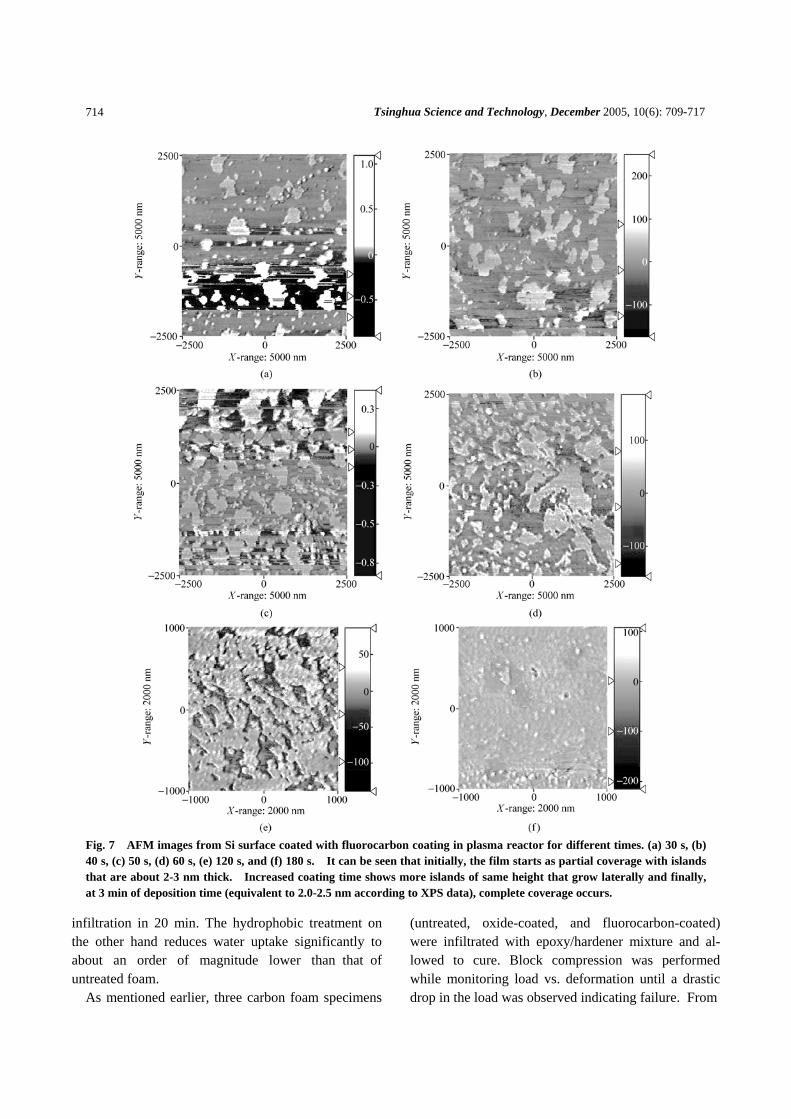
The AFM data at each step was clearly monitored. Figure 7 shows the AFM phase images of fluorocarbon growth on Si. It shows that the coating starts as patches that have an average thickness of about 3 nm. These patches keep nucleating on the substrate continuously and grow laterally to merge into complete coatings. It can be seen that complete coverage of the Si occurs at
3 min coating time for the fluorocarbon film (less than 3 nm average thickness measured by XPS). Similar study on the oxide film shows complete coverage within 1 min for coating time, equivalent to about 3.5 nm of overall thickness.
2.2 Influence of nano-coatings on dispersion of carbon nanofibers in organic medium
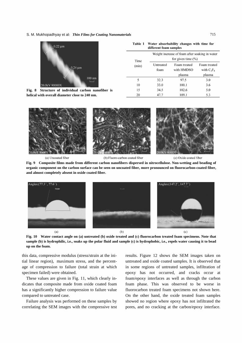
Thin layers of coated and uncoated carbon nanofibers dispersed in nitrocellulose were prepared on glass and analyzed using SEM. Figure 8 shows the structure of a single fiber, and Fig. 9 shows the microstructures of the fiber-nitrocellulose composite. It can be seen that untreated nanofibers are agglomerated and show no-ticeable “beading” of the organic solution before dry-ing. This indicates insufficient affinity between nano-fibers and organic medium. This effect is more pro-nounced in fibers treated with CF2 nano-coating. On the other hand, fibers treated with silica nano-coating shows no beading effect, and uniform spreading of or-ganic solution on the fiber surface to form a relatively well-dispersed composite. This observation shows that a nano-thin coating of silica can be effective in dispers-ing nano-structures into organic matrix materials.
2.3 Influence of nano-coatings on microcellular foam
The influence of two plasma coatings on wettability (contact angle with water) of foam is shown in Fig. 10. It can be clearly seen that oxide coated foam (<5 nm effective coating thickness) soaks up water rapidly and that treated with fluorocarbon-containing plasma (simi-lar thickness estimate) becomes hydrophobic. Com-pared to untreated foam (that has a contact angle of about 77o), HMDSO-treated foam has a contact angle of 0° and fluorocarbon-treated foam has a contact an-gle higher than 140o, same as that of commercial Teflon.
In a micro-porous surface, such as foam, an estimate of surface affinity for epoxy or other polar compounds can be made from the amount of the water adsorbed in a given time. The amounts of water absorbed by un-treated and differently treated foam samples were compared. Results in Table 1 indicate that significant changes in water absorbability are observed in the plasma treated foams. Compared to untreated foam, HMDSO-plasma treated foam has a 129% higher water
Tsinghua Science and Technology, December 2005, 10(6): 709-717
714
Fig. 7 AFM images from Si surface coated with fluorocarbon coating in plasma reactor for different times. (a) 30 s, (b) 40 s, (c) 50 s, (d) 60 s, (e) 120 s, and (f) 180 s. It can be seen that initially, the film starts as partial coverage with islands that are about 2-3 nm thick. Increased coating time shows more islands of same height that grow laterally and finally, at 3 min of deposition time (equivalent to 2.0-2.5 nm according to XPS data), complete coverage occurs.
infiltration in 20 min. The hydrophobic treatment on the other hand reduces water uptake significantly to about an order of magnitude lower than that of untreated foam. As mentioned earlier, three carbon foam specimens
(untreated, oxide-coated, and fluorocarbon-coated) were infiltrated with epoxy/hardener mixture and al-lowed to cure. Block compression was performed while monitoring load vs. deformation until a drastic drop in the load was observed indicating failure. From
S. M. Mukhopadhyay et al:Thin Films for Coating Nanomaterials 715
Fig. 8 Structure of individual carbon nanofiber is helical with overall diameter close to 240 nm.
Fig. 9 Composite films made from different carbon nanofibers dispersed in nitrocellulose. Non-wetting and beading of organic component on the carbon surface can be seen on uncoated fiber, more pronounced on fluorocarbon-coated fiber, and almost completely absent in oxide coated fiber.
Fig. 10 Water contact angle on (a) untreated (b) oxide treated and (c) fluorocarbon treated foam specimens. Note that sample (b) is hydrophilic, i.e., soaks up the polar fluid and sample (c) is hydrophobic, i.e., repels water causing it to bead up on the foam.
this data, compressive modulus (stress/strain at the ini-tial linear region), maximum stress, and the percent-age of compression to failure (total strain at which specimen failed) were obtained. These values are given in Fig. 11, which clearly in-dicates that composite made from oxide coated foam has a significantly higher compression to failure value compared to untreated case. Failure analysis was performed on these samples by correlating the SEM images with the compressive test
results. Figure 12 shows the SEM images taken on untreated and oxide coated samples. It is observed that in some regions of untreated samples, infiltration of epoxy has not occurred, and cracks occur at foam/epoxy interfaces as well as through the carbon foam phase. This was observed to be worse in fluorocarbon treated foam specimens not shown here. On the other hand, the oxide treated foam samples showed no region where epoxy has not infiltrated the pores, and no cracking at the carbon/epoxy interface.

Tsinghua Science and Technology, December 2005, 10(6): 709-717
716
Crack propagation was always within the graphitic region indicating that bonding at the epoxy-graphite interface was strong enough to prevent debonding. This may account for higher deformation resistance of these composites. This study indicates that the nano-scale silicon oxide coating produced here enhances intimate inter-dispersion between C and epoxy and their bond strength, leading to tougher composites.
Fig. 11 Stress strain graph of composites made by in-filtrating coated and uncoated graphitic foams with epoxy. It can be seen that the foam with oxide-nanocoating gives the toughest composite (Highest compression prior to failure, and highest energy for failure). “Psi” is pounds per square inch.
Fig. 12 Crack propagation in the foam-epoxy com-posites (a) uncoated foam and (b) oxide coated foam. Note the complete absence of cracks at the foam epoxy interfaces in (b). This is attributed to increase bond strength between the foam and the matrix due to the silica-nanolayer.
3 Concluding Remarks
Nanometer scale oxide and fluorocarbon coatings on model flat surfaces as well on uneven porous solids have been investigated. It can be seen that the coatings start forming as patchy islands, which grow laterally to form complete coverage at thicknesses as low as 3-4 nm.
These coatings are also found to provide effective surface property modifications. The silica-like coating enhances bonding between carbon and epoxy, and in-filtration of polar organic liquids into the foam. This is reflected in the absence of interfacial de-lamination, and increased fracture toughness of composites made from oxide coated foam. This is also apparent from the observation that oxide-coated nanofibers are uniformly wetted by nitrocellulose solution to form a well-dispersed composite structure. The fluorocarbon coat-ing makes the surface inert and moisture repellent, as indicated by the increase in water contact angle, and the decrease of infiltration and wettability with organic fluids such as epoxy and nitro-cellulose. This nano-film will be useful in stand-alone applications of high surface area materials preventing environmental deg-radation of the surface.
Acknowledgements
The authors are grateful to the following investigators for col-laboration and feedback in different areas: Prof. S. Higgins at Wright State University for the AFM data; Dr. A. K. Roy at Air Force Research Laboratory for composite fabrication and me-chanical testing with foam.
References
[1] Kumar A, Chung Y W, Moore J J, Smugeresky J E. Sur-face engineering: Science and technology I. In: Proceed-ings of Symposium Sponsored by TMS, 1999.
[2] Strafford K N, Datta P K, Gray J S. Surface Engineering Practice: Processes, Fundamentals and Applications in Corrosion and Wear. Ellis Horwood Ltd., 1990.
[3] Sudharshan T S. Surface Modification Technologies: An Engineering’s Guide. NY: Mercel Dekker Inc., 1989.
[4] Sudharshan T S, Bhat D G. Surface modification technolo-gies II. In: Proceedings and Second Intl. Conf. Surface Modification Technologies, 1989.
[5] Sheshan K. Hand Book of Thin Film Deposition Processes and Technique, Second Edition. Noyes Publications, 2002.
[6] Elshabini-Riad A, Barlow F D III. Thin Film Technology

S. M. Mukhopadhyay et al:Thin Films for Coating Nanomaterials 717
Handbook. McGrow Hill, 1997. [7] Mittal K L, Pizzi A. Adhesion Promotion Techniques:
Technological Applications. New York: M. Dekker, 1999. [8] Donnet J-B, Wang T K, Peng J C M. Carbon Fibers. New
York: Marcel Dekker, 1998: 161-230. [9] Scolar D A. Interfaces in polymer matrix composites. In:
Composite Materials, Vol. 6. New York: Academic Press, 1974: 217-284.
[10] Rhee H W, Bell J P. Effects of reactive and non-reactive coatings upon the performance of graphite epoxy composites. Polym. Composites., 1991, 12: 213-225.
[11] Dujardin S, Lazzaroni R, Riga L, Riga J, Verbist J J. Elec-trochemically polymer coated carbon fibers-characterization and potential for composite applications. J. Mater. Sci., 1986, 21: 4342-4346.
[12] Kettle A P, Jones F R, Alexander M R, Short R D, Stol-lenwerk M, Zabold J, Michaeli W. Experimental evalua-tion of the interphase region in carbon fiber composites with plasma polymerized coatings. Composites Part A: Applied Science and Manufacturing (Incorporating Com-posites and Composites Manufacturing), 1998, 29(3): 241-250.
[13] Inagaki N. Plasma Surface Modification and Plasma Po-lymerization. Technomic Publishing Inc., 1996.
[14] Yasuda H. Plasma Polymerization. Academic Press Inc., 1985.
[15] Grill A. Cold Plasma in Materials Fabrication: From Fun-damentals to Applications. NY: IEEE Press, 1994.
[16] d’Agostino R. Plasma Deposition, Treatment and Etching of Polymers. Boston Academic Press, 1990.
[17] Regnier C, Tristant P, Desmaison J. Surface and Coatings Technology, 1996, 80: 18-22.
[18] Schwarz J, Schmidt M, Ohl A. Surface and Coatings Technology, 1998, 98: 859-864.
[19] Hegemann D, Vohrer U, Oehr C, Riedel R. Surface and Coatings Technology, 1999, 116-119: 1033-1036.
[20] Krentsel E, Yasuda H, Miyama M, Yasuda T. J. Poly. Sci. A: Poly. Chem., 1995, 33: 2887-2892.
[21] Coulson S R, Woodward I S, Badyal J P S, Brewer S A, Willis C. J. Phys. Chem. B, 2000, 104: 8836-8840.
[22] Durand E, Labrugere C, Tressaud A, Renaud M. Plasmas and Polymers, 2002, 7(4): 311-325.
[23] Wertheimer M R, Klemberg-Sapieha J E, Cerny J, Liang S. Plasmas and Polymers, 1998, 3(3): 151.
[24] Mukhopadhyay S M, Joshi P, Datta S, MacDaniel J. Plasma assisted surface coating of porous solids. Applied Surface Science, 2002, 201: 219-226.
[25] Mukhopadhyay S M, Joshi P, Datta S, Zhao J G, France P. Plasma assisted hydrophobic coatings in porous materials. J. Phys. D: Appl. Phys., 2002, 35: 1927-1933.
[26] Klett J, Hardy R, Romine E, Walls C, Burchell T. Carbon, 2000, 38: 953.
[27] Kearns K M. US Patent No. 5868974, February 1999. [28] Stiller A H, Stansberry P G, Zondlo J W. US Patent No.
5888469, March 1999. [29] Weichmann L. Mater. Res. Bull., 2000, 25: 10. [30] Kearns K M. In: Proceedings of 21st Annual Conference
on Ceramic, Metal and Carbon Composites, Materials and Structures. Cocoa Beach, Florida, January 1997.
[31] Tibbets G G, Mchugh J J. Mechanical properties of vapor-grown carbon fiber composites with thermoplastic matri-ces. J. Mater. Res., 1999, 14: 2871-2880.
[32] Paredes J I, Martinez-Alonso A, Tascon J M D. Surface characterization of submicron vapor-grown carbon fibers by scanning tunneling microscopy. Carbon, 2001, 39: 1575-1587.
[33] Patton R D, Pittman Jr. C U, Wang L, Hill J R. Vapor grown carbon fiber composites with epoxy and poly (phenylene sulfide) matrices. Composites Part A: Applied Science and Manufacturing (Incorporating Composites and Composites Manufacturing), 1999, 30(9): 1081-1091.
[34] Mukhopadhyay S M, Mahadev N, Joshi P, Roy A K, Kearns K M, Anderson D P. Structural investigation of graphitic foam. Journal of Applied Physics, 2002, 91(5): 3415-3420.
[35] Seah M P, Dench W A. Surface and Interface Analysis, 1979, 1: 2.
[36] Tauma S, Powell C J, Penn D R. Surface and Interface Analysis, 1994, 21: 165.