a superhydrophobic coating : fluorophilic silica nanoparticle … · 2013-08-15 · a...
TRANSCRIPT

A Superhydrophobic Coating : Fluorophilic Silica Nanoparticle-Doped Teflon Films
by
Sijia Wang
BS, Shandong University, 2010
Submitted to the Graduate Faculty of
The Kenneth P. Dietrich School of
Arts and Sciences in partial fulfillment
of the requirements for the degree of
Master of Science
UNIVERSITY OF PITTSBURGH
2013

ii
UNIVERSITY OF PITTSBURGH
DIETRICH SCHOOL OF ARTS AND SCIENCES
This thesis was presented
by
Sijia Wang
It was defended on
August 9, 2013
and approved by
Dr. Haitao Liu, Assistant Professor, Department of Chemistry
Dr. Jill Millstone, Assistant Professor, Department of Chemistry
Thesis Director: Dr. Stephen G. Weber, Professor, Department of Chemistry

iii
Copyright © by Sijia Wang
2013

iv
Coatings prepared from a suspension of fluoroalkyl-silane modified silica nanoparticles
(FNPs) in a solution containing Teflon AF 2400 show wetting properties that depend on
composition and the method of film formation. Static contact angle and sliding angle
measurements revealed that adding FNPs improved their water repellency. Specifically, water
droplets have static contact angles of 120-151 ° on FNP-containing films, compared with 114.6°
on a FNP-free Teflon AF coated surface. Static contact angles increase with the weight percent
of FNPs. Superhydrophobic (contact angle >150° and sliding angle <10°) states were achieved
on films with 70% weight percentage of 510 nm FNPs. Surface morphologies were determined
by scanning electron microscopy (SEM) and atomic force microscopy (AFM). Spin coating was
later proved a better film fabrication method than solution-cast deposition, in terms of surface
morphology and sliding angles.
A Superhydrophobic Coating : Fluorophilic Silica Nanoparticle Doped Teflon Films
Sijia Wang, MS
University of Pittsburgh, 2013
Prof. Stephen G. Weber

v
TABLE OF CONTENTS
1.0 INTRODUCTION ........................................................................................................ 1
1.1 SUPERHYDROPHOBIC SURFACE ................................................................ 1
1.2 MODELS OF SUPERHYDROPHOBIC STATES .......................................... 2
1.3 FLUOROUS MATERIALS: TEFLON AF 2400 .............................................. 3
2.0 EXPERIMENTAL SECTION .................................................................................... 8
2.1 REAGENTS ......................................................................................................... 8
2.2 NANOPARTICLE PREPARATION AND FLUORINATION ...................... 8
2.3 FILM PREPARATION AND CHARACTERIZATION ............................... 10
3.0 RESULTS AND DISCUSSION ................................................................................ 12
3.1 PROPERTIES OF FLUOROUS SILICA PARTICLES ............................... 12
3.1.1 Preparation of Silica Particles ...................................................................... 12
3.1.2 Characterization of Silica Particles .............................................................. 13
3.2 WETTING PROPERTIES ............................................................................... 14
3.3 SURFACE MORPHOLOGY ANALYSIS ...................................................... 18
3.4 SOLUTION-CAST DEPOSITION .................................................................. 21
4.0 CONCLUSION ........................................................................................................... 25
ACKNOWLEDGEMENT .......................................................................................................... 26
BIBLIOGRAPHY ....................................................................................................................... 27

vi
LIST OF TABLES
Table 1. Summary of wettability measurements and comparasion to calculated values .............. 20

vii
LIST OF FIGURES
Figure 1. Wetting state (a ) Wenzel, (b) Cassie –Baxter and (c) combined models ....................... 3
Figure 2. Three immiscible phases ................................................................................................. 4
Figure 3. Structure of Teflon AF 2400 .......................................................................................... 5
Figure 4. Dependece of partice size on initial ammonium concentration..................................... 12
Figure 5. SEM images of particles with 50, 120, 300 and 510 nm diameter ................................ 13
Figure 6. Static contact angle measurement on Teflon AF 2400 films with 5%, 10%, 15%, 30%,
50%, 70% and 85% (wt%) 510 nm FNP ...................................................................................... 16
Figure 7. Static contact angle (a) and sliding angle (b) of 4 µL water on spin-coat surfaces. Films
were prepared with 120, 310 and 510 nm FNPs, with wt% of 5%, 10%, 15%, 30%, 50%, 70%
and 85% ...................................................................................................................................... 17
Figure 8. AFM images of (a) 120 nm, (b) 310 nm and (c) 510 nm FNP (wt% = 70%) doped
Teflon films with 5 µm scan size .................................................................................................. 18
Figure 9. Static contact angle and sliding angle of spin coat and solution – cast 120 nm FNP
doped Teflon films ........................................................................................................................ 23
Figure 10. SEM images and of (a) spin-coat and (b) solution-cast deposited films with 70%
(wt%) 120nm FNP ....................................................................................................................... 24

1
1.0 INTRODUCTION
1.1 SUPERHYDROPHOBIC SURFACE
Surfaces with a water contact angle greater than 150° and a sliding angle less than 10° are
defined as superhydrophobic1-3. It was discovered that some natural surfaces, such as the lotus
leaf4,5, exhibit remarkable water-repellent and self-cleaning properties6 based on their
combination of a hydrophobic wax layer and a hierarchically rough microstructure. Recently,
fabricated superhydrophobic surfaces have found their applications in areas such as dust-free
coatings, water-proof textiles, and microfluidic devices7.
As described by Cassie and Baxter8, multi-level roughness enables trapping of air under
the water droplet, enhancing the surface hydrophobicity8-11. Microstructured pillar arrays
fabricated by photolithography12,13 and soft lithography14,15 are often used to provide a
predefined roughness. The major issues facing wide application of these techniques include high
fabrication cost, limited application to large scale coating, and reduced flexibility in modulation
of surface morphologies. One of the low-cost alternatives is through surface deposition of
nanoparticles16-19. As silica nanoparticles are readily synthesized by a sol-gel process20-22 with
uniform size, and as their surface chemistry is tunable via covalent modification, they are widely
used in creating surfaces with desirable properties. Tsai et al. have fabricated raspberry-like
particulate coatings by layer-by-layer assembly of two different sizes of silica nanoparticles,

2
which resulted in superhydrophobic surfaces23. Karunakaran et al. reported on superhydrophobic
film prepared by sequential dip coating of 3-aminopropyltrimethoxysilane-functionalzied silica
particles of two different sizes ( 20 and 100 nm)24. Ling et al. have created stable and transparent
superhydrophobic films by deposition of silica nanoparticles onto an amine-terminated substrate,
followed by 1H, 1H, 2H, 2H-perfluorodecyltriethoxysilane (PFTS) gas-phase deposition25.
Ogihara et al. recently reported on spraying alkylsilane-modified nanoparticles on paper
substrates26. Moreover, randomly packed surfaces prepared via spin coating usually have
enhanced surface roughness than the hexagonally ordered structures27.
1.2 MODELS OF SUPERHYDROPHOBIC STATES
Wenzel’s28 and Cassie and Baxter’s8 models are used to explain the effect of surface
roughness on its wettability (Fig 1). According to Wenzel, liquid is in intimate contact with the
structured surface, and hydrophobicity is due to the enhanced surface area of solid. The contact
angle derived from this model is given as:
cosϴeW=rcosϴo
where the roughness factor r > 1is the ratio of the true surface area and the projected area, and ϴo
is the contact angle on flat surface. Wenzel’s model applies only when the flat surfaces is
hydrophobic (ϴo>90°), otherwise adding roughness will make the surface more hydrophilic.
In the Cassie-Baxter model, water does not completely penetrate into the spaces on the
surface, and air remains trapped under the water drop. Consequently, the droplet sits partially on

3
the solid with f as the fraction of the surface area that contacts the droplet, and (1- f) as the
fraction of the droplet in contact with trapped air. The contact angle is
cosϴC-B= f (cosϴo+1)-1.
This model is frequently applied to surfaces with small sliding angle, which is defined as
a critical angle where a water drop begins to roll off the tilted surface. Surfaces with complex
roughness can be described in terms of both models29-31.
(a) (b) (c)
Fig. 1 Wetting states (a) Wenzel, (b) Cassie-Baxter, and (c) combined models
1.3 FLUOROUS MATERIALS: TEFLON AF 2400
Fluorous compounds are defined as “of, relating to, or having the characteristics of
highly fluorinated saturated organic materials, molecules, or molecular fragments”32.
Fluorocarbons generally form a separate phase in the presence of organic solvent and water (Fig.
2). This unusual miscibility property is due to the large difference of the Hildebrand’s solubility
parameter33, δ, which is defined as the square root of the cohesive energy density, or the heat
needed for vaporization of a pure component over its molar volume. For example, the difference
in solubility parameter makes perfluorohexane (δf = 12.3 MPa1/2) phase separate from hexane

4
(δo = 14.9 MPa1/2)33. The decreased solubility parameters for fluorocarbons are due to the weak
van der Waals interactions between the F-containing compounds. Therefore, fluorocarbons are
expected to partition to fluorous over organic or aqueous solvent. This tendency is termed
“fluorophilic”34.
Fig.2 Three immiscible phases
Organic solutes are rendered “fluorophilic” by covalently functionalizing them with one
or more fluorocarbon ponytails [(CH2)m(CF2)n-1CF3]35.Thus modified, organic compounds
become more compatible with fluorous solvents. Generally, solubility depends on the length and
composition of the fluorocarbon chains. More incorporated -CF2- groups results in a smaller
solubility parameter and a larger partition coefficient to fluorous solvents. Moreover, the
partition coefficients of fluorous solutes in fluorous biphasic systems can be estimated based on
the structure of solutes36. The reduced solubility parameter improves the transport selectivity of
fluorous solvents for fluorinated molecules over non-fluorous compounds, and consequently
benefits its application in preparation of selective extraction devices, biphasic catalytic recycling
system, as well as hydrophobic surfaces37-41.
Generally, the wettability behavior of rough surfaces is governed by the interface
chemistry. Specifically, hydrophobicity is favored with reduced surface energy42, which inspires
the use of fluoroalkyl [(CH2)m(CF2)n-1CF3] functionalized materials and perfluoropolymers12,43-47.

5
For example, Raza et al. applied 1H, 1H, 2H, 2H-perfluorodecyltichlorosilane to control the
wetting behavior of silica nanoparticle arrays48. Lau et al. used a poly(tetrafluoroethylene)
(surface energy 18 mN/m) coating to reduce the adhesion in vertically aligned carbon nanotube
forests49. Recently, Brassard et al. reported on layer-by-layer thin film coatings prepared using
fluorinated silica nanoparticles only46,50. However, such coatings were fragile considering their
all-particle composition. Nilsson et al. fabricated surfaces with hydrophobic properties on Teflon
by roughing the surface with sandpaper51. Recently, Singh et al. reported on Teflon coated
graphene sheet as a stable superhydrophobic structure52. However, the influence of graphene
structure on its wetting behavior was not fully discussed. And also, the template-directed vapor
deposition method they used can be expensive and laborious.
CF2-CF2 n
Teflon AF 2400
OO
F F
CF3CF3
m
Fig. 3 The structure of Teflon AF 2400
Herein Teflon AF 2400 was employed in fabricating superhydrophobic films. As a
commercially available, soluble perfluoropolymer, Teflon AF 2400 (Fig. 3) is widely used to
take advantage of its solubility, thermal and chemical stability, mechanical robustness, as well as
the low surface energy (~16 mN/m)53. For instance, Teflon AF has been used to coat a wide
variety of roughened surfaces, e.g., aluminum54,55, ZnO56, steel with an electropolymerized
layer57, and fiber mats of carbon58 and glass59. While these approaches are very useful, their

6
wettability depends upon the underlying material structure. Electrospun fibers with Teflon AF
have been created60-62. These fibers can be used as a coating to form superhydrophobic surfaces
from, in principle, any material. Liu et al. have created an approach in which alkyl or
fluoroalkyl-containing particles created in a sol-gel process are combined with a latex
formulation and a crosslinker63,64. This mixture can be sprayed onto, for example, fabrics to
create effectively superhydrophobic materials. Formulations for superhydrophobic coatings that
do not depend on the inherent roughness of the substrate, and which do not require complex
processing are desirable.
Despite the wide use of Teflon AF and nanoparticles in superhydrophobic studies,
combinations of the two are surprisingly rare. Bayer et al. fabricated hydrophobic coatings on
sandpapers on which submicrometer Teflon particles (average size of ~150 nm) were
deposited65. This work has limitations, however, as the surface roughness was largely dependent
on the substrate morphology and the sliding angles are as high as ~10 ° to ~ 40 °. Liu et al. in one
of their formulations used a latex incorporating a fluoropolymer with hydroxyl groups. In the
process of deposition by spin coating, the sol-gel process creates silica particles (µm dimensions)
with a bumpy, strawberry-like surface of fluorpolymer latex particles63.
Our desire was to understand a simple system containing fluorous nanoparticles and a
fluoropolymer binder. Our goal was to find the dependence of contact angle and sliding angle on
particle size and composition. In our work, Teflon AF films were created by both spin-coating
and casting (slow solvent evaporation) on smooth glass slides. The effect of the presence of
FNPs was evaluated quantitatively. Suspensions of Teflon AF 2400 and FNPs with different
diameters with various weight percent FNPs were used in the coating process. The dependence
of surface wettability on the particle sizes and the weight percent of FNPs (wt% FNP) were

7
investigated. Spin coating66 was compared with solution-cast deposition67,68 for one particle
diameter.

8
2.0 EXPERIMENTAL SECTION
2.1 REAGENTS
Colloidal silica particle with 120 nm diameter (IPA-ST-ZL) was a gift from Nissan
Chemical Co. (Tokyo, Japan). Telflon AF 2400 was purchased from DuPont (Wilmington, DE).
HFE-7100 (a mixture of methyl nonafluorobutyl and nonafluoroisobutyl ethers) and Fluorinert
FC-72 (a mixture of perfluorohexanes) were purchased from 3M (Minneapolis, MN). 1H, 1H,
2H, 2H-perfluorooctyltriethoxysilane, ammonium hydroxide (28%-30%), tetraethylorthosilicate
(TEOS), ethanol and isopropanol were obtained from Sigma-Aldrich (St. Louis, MN).
2.2 NANOPARTICLE PREPARATION AND FLUORINATION
In a typical sol-gel process, the concentration of ammonium hydroxide is a strong factor
in determining the final size of the silica particles21. Accordingly, a series of pilot experiments
were conducted to determine this dependence. In a 500 mL flask, 5.6 mL TEOS was stirred with
19.4 mL ethanol. Following a short time, 18 mL of ethanol and 6 mL H2O were added. After
stirring for 10 minutes, a certain amount of ammonium hydroxide (0.5, 1.0, 1.5 and 2.0 mL,
respectively) was added. To avoid a sharp increase in local concentration, which usually result in

9
discrepancy in particle size, it was added with syringe with a rate controlled at 5 seconds per
drop. Particle diameters were measured after 2, 4 and 10 hours with dynamic light scattering.
Large particles, 510 and 310 nm, were synthesized as follows. To prepare the 510 nm
silica particles, the staring materials, namely TEOS, H2O, and ethanol were added exactly as in
the pilot trials, and the hydrolysis step was allowed to proceed for 10 minutes. Following this, a
solution of 2 mL ammonium hydroxide was added with syringe and the reaction was allowed to
proceed at room temperature for 5 hours. The suspension was centrifuged at 6000 rpm for 30
minutes. The pellet was resuspended in fresh ethanol to wash away unreacted TEOS. To obtain
310 nm silica particles, a solution of 120 nm silica (IPA-ST-ZL, 2 mL) was stirred with 27 mL
isopropanol at room temperature, followed by adding 15 mL TEOS. Then a mixture of 1.5 mL
ammonium hydroxide in a solution of 20 mL isopropanol and 6 mL H2O was added as catalyst.
The reaction proceeded for 5 hours. The workup process was the same as above.
A typical procedure for particle modification included: 1) suspend silica nanoparticles
(3.0 g) in a solution of isopropanol (35 mL) and HFE-7100 (25 mL); 2) add 1H, 1H, 2H, 2H-
perfluorooctyltriethoxysilane (2 mL) as flouroalkane tags; and 3) add ammonium hydroxide (10
mL) in isopropanol (25 mL) to modulate the pH to about 10. The reaction mixture was then
refluxed in an oil bath at 80 °C for 3 days. The modified nanoparticles was centrifuged (6000
rpm, 30 minutes) and resuspended in fresh washing solvent (ethanol: HFE-7100 = 2:1; v/v) for 3
cycles to wash away excess silane reagent.
For imaging, the suspension of silica particles in ethanol was spread on micro glass
slides, and then sputter-coated with palladium to enhance surface conductivity. The images of
silica particles were captured using a Philips XL-30 SEM (Hillsboro, OR).

10
2.3 FILM PREPARATION AND CHARACTERIZATION
Glass microscope slides (25 x 19 x 1 mm) from Fisher Scientific (Hampton, NH) were
used as film casting substrates. To remove dust and impurities, the glass slides were cleaned with
a heated mixture of concentrated sulfuric acid and hydrogen peroxide (piranha solution) at a ratio
of 3:1 (v/v). (Caution: Piranha solution reacts violently with organic compounds and should be
handled with extreme care.) This process was performed at 80 °C for 30 minutes, followed by
rinsing with D.I. water. Cleaned glass slides were reserved in fresh ethanol.
To prepare the coating solution, FNPs (120, 310 and 510 nm) were mixed with Teflon
AF 2400 in a solvent of FC-72 (2.5 mL) at room temperature to form a homogeneous
suspension. In each solution, the total mass of FNP and Teflon AF 2400 was 62.5 mg, with
wt%FNP varying from 5% to 85%. Films were prepared by spin coating at 3000 rpm on the
substrates layer by layer (4 layers in total) at a constant spin time of 40 seconds, before they were
cured at 120 °C overnight.
FNP doped Teflon AF 2400 films were prepared by solution-cast deposition, as a
comparison with the spin coating method. A total amount of 125 mg FNP and Teflon AF 2400
were mixed in 5 mL solvent of HFE-7100/ FC-77 = 2 : 1 (v/v), with wt%FNP vary from 5% to
70%. In a casting process, the coating solution evaporates slowly in an optical-flat-bottomed
Petri dish (i.d. 6.0 cm) at room temperature for 5-7 days until a solid film is formed. To get
controlled evaporation, the dish was covered carefully to ensure an environment of saturated
solvent vapor, and the casting platform was kept steady during the process.
The wetting properties were later characterized with a VCA 2000 video contact angle
system (Advanced Surface Technology, Inc. Billerica, MA) with 4 μL droplets. Advancing and
receding angles were measured by automatically adding/withdrawing water with a needle in the

11
water droplet. Contact angles were measured when water drop started to expand /contract.
Sliding angles were calculated as the averaged difference in advancing and receding angle. All
values were averaged over three different spots. Surface morphology was investigated with a
Philips XL-30 SEM (Hillsboro, OR) after being sputter-coated with palladium. AFM
measurements were conducted by PPG Industries (PA) with Digital Instruments Dimension 3000
microscope (Bruker Nano, Karlsruhe, Germany).

12
3.0 RESULTS AND DISCUSSION
3.1 PROPERTIES OF FLUOROUS SILICA PARTICLES
3.1.1 Preparation of Silica Particles
As shown in Fig. 4, the size of synthesized silica nanoparticles is affected by the initial
concentration of ammonia. Particle size increases during the first 4 hours and then growth stops.
Based on the result, 2 mL of ammonia were used in preparation of 510 nm silica particles and 1.5
mL was used for the 310 nm.
0 4 8 12
0
100
200
300
400
500
Parti
cle
Diam
eter
by
DLS
(nm
)
Reaction Time (hr)
0.5ml 1.0ml 1.5ml 2.0ml
Fig. 4 Dependence of particle size on initial ammonia concentration.

13
3.1.2 Characterization of Silica Particles
Particle diameters were measured with SEM (Fig. 5). The 310 and 510nm particles show
low polydispersity in SEM images, indicating the effectiveness of the sol-gel process in particle
synthesis. Also notice that twin and triplet silica particles were found in the 310 nm preparation.
Fig.5 SEM images of particles with 120, 310 and 510 nm diameter
According to elemental analysis (C, H, F %), the surface concentrations of fluoroalkyl
tags on 120, 310 and 510 nm FNPs are 3.2 ± 0.1, 7.2 ± 0.2 and 7.6 ± 0.1 μmol/m2, respectively.
These values are based on the assumption that the fluoroalkyl tags are the only source of
fluorine, and that the specific surface areas are those of nonporous spheres, 30.0, 13.5 and 7.1
m2/g for 120, 310 and 510 nm particles, respectively. The surface concentration of F-tag is
120nm 310nm
510nm

14
calculated via the following equation (atomic mass of fluorine is 19 g/mol and 13 fluorines per
molecule):
𝑠𝑢𝑟𝑓𝑎𝑐𝑒 𝑐𝑜𝑛𝑐𝑒𝑛𝑡𝑟𝑎𝑡𝑖𝑜𝑛 =𝐹 %19∗13
(1 − 𝐶 % − 𝐹 % − 𝐻 %) ∗ 𝑠𝑝𝑒𝑐𝑖𝑓𝑖𝑐 𝑠𝑢𝑟𝑓𝑎𝑐𝑒 𝑎𝑟𝑒𝑎
The surface coverages for the 310 and 510 nm particles are high as the surface coverage
of silanol groups on silica particle is ~8 μmol/m2. We infer that there is some porosity or
roughness at the surface of the 310 and 510 nm particles.
3.2 WETTING PROPERTIES
Fig. 6 shows the static contact angles of films with particles of different diameters (120,
310 and 510 nm) and weight percentages (5%, 10%, 15%, 30%, 50%, 70% and 85%). As shown
in Fig. 7 (a), the static contact angle generally increases with wt% FNP. For the 510 nm FNP
doped Teflon films, for instance, those with 5%, 10%, 15%, 30% and 50% FNPs have static
contact angles of 126.2 ± 0.6, 126.6 ± 0.3, 137.8 ± 0.5 and 146 ± 0.4°, respectively. Stated errors
are the standard deviation of the mean. Further increasing the FNP weight percentage to 85%,
however, decreases the static contact angle to 148.4 ± 1.0°. This trend is also observed in 310 nm
FNP doped Teflon films, where the 70% film (static contact angle 150.7 ± 0.4°) is slightly more
hydrophobic than the 85% film (static contact angle 149.2 ± 0.6°). The influence of particle size
and weight percentage on sliding angles is shown in Fig. 7 (b). The smallest sliding angles are
reached on 70% FNP doped films in each group, and those with 85% FNP also have decent
water repellent properties with sliding angles less than 10°. This is in accordance with our

15
observation that the water droplets are more prone to roll off surfaces with high percentage of
nanoparticles. Superhydrophobicity is reached on the film with 70% 510 nm FNP, giving a static
contact angle of 151.1 ± 0.3° and sliding angle of 5.5 ± 0.6°.
Ogihara et al. reported that the static contact angle reaches 148° on paper spray-coated
with alkyl silane modified silica nanoparticles26. These authors suggest that nanometer- and
micrometer-sized roughness was formed by the particles. As mentioned above, the presence of a
hierarchical structure contributes favorably to superhydrophobicity. In their work, there is
inherently roughness within paper structure itself, which is augmented by the spray coating. In
the work presented here, smooth glass slides were used as substrates. The structural attributes of
the surfaces arise solely from the silica particles, the polymer, and the method of application. The
surface hydrophobicity is comparable to those on rough substrate, with static contact angles
reaching as high as ~151°. We are able to modulate the wetting behavior of smooth surfaces by
simply adjusting the composition of the coating solution. It has been reported that the wetting
behavior of superhydrophobic coatings can be controlled by using particles of different sizes50.
According to the cited work, the surface hydrophobicity increases with the particle size (40-300
nm) on all-particle coatings. In the current work, the surface hydrophobicity is easily tuned by
adjusting the weight percentage of silica nanoparticles in the films, which is simple and effective.
Brassard et al. also claimed that large particles provide more space for air entrapment, enhancing
the water repellent performance according to the Cassie-Baxter model50. Interestingly, this is in
contradiction with Saji et al. that larger silica particles (25, 250 and 500 nm were used in their
experiments) showed less hydrophobicity on spray coated materials69. We find that the particle
size is not as important as the particle wt%. However, in the 70% FNP-doped films the size
dependence is in accordance with Brassard et al.’s statements: films doped with 120, 310 and

16
510 nm FNPs have static contact angles of 144.7 ± 0.8, 150.7 ± 0.2 and 151.1 ± 0.3 °,
respectively. At other wt%FNP, however, this trend is not obeyed strictly. In the 30% FNP doped
films, for instance, those with 120 nm FNPs (static contact angle 135.4 ± 0.4 °) are more
hydrophobic than the 310 nm FNPs doped counterparts (static contact angle 130.3 ± 0.6 °). Both
Brassard and Saji agreed that the volume of voids increase with particle size, but they reached
opposite conclusions. Based on our observations, while particle size has an influence, it is by no
means the most significant variable. The most significant variable is the particle wt%. An
inference from the data is thus that the structures created, the random piles of particles arising
from the three particle sizes, are probably on average geometrically similar. In this way, as the
droplet contact area per particle increases, so does the area in contact with trapped air.
Fig. 6 Static contact angle measurement on Teflon AF 2400 films with 5%, 10%, 15%, 30%,
50%, 70% and 85% (wt%) 510nm FNP.
5% 10% 15% 30% 50% 70% 85%

17
0 20 40 60 80 100100
110
120
130
140
150
160 120nm 310nm 510nm
Stat
ic C
A of
Tef
lon/
FNP
(o )
FNP wt%
(a)
0 20 40 60 80 1000
10
20
30 120 nm 310 nm 510 nm
Slid
ing
Angl
e of
Tef
lon/
FNP
(o )
FNP wt%
(b)
Fig. 7 Static contact angle (a) and sliding angle (b) of 4 μL water on spin-coated surfaces. Films
were prepared with 120, 310 and 510nm FNPs, with wt% FNP of 5%, 10%, 15%, 30%, 50%, 70%
and 85%.

18
3.3 SURFACE MORPHOLOGY ANALYSIS
AFM images were used to investigate the effect of surface morphology on film
wettability. According to the 3D images of 70% FNP-doped Teflon films (Fig. 8), spherical
particles piled up randomly in clusters, instead of forming mono- or multilayer arrays on the
surface. The qualitative picture provided by the images is supported by quantitative estimates of
roughness. The experimental RMS roughness was much larger than the calculated values based
on the hexagonal close-packed monolayer (Table 1).
(a)

19
(b)
(c)
Fig. 8 AFM images of (a) 120nm, (b) 310nm, (c) 510nm FNP (wt% = 70%) doped Teflon films
with 5μm scan size.

20
Table 1: Summary of wettability measurements and comparison to calculated values.
FNP RMS
(experimental, nm)* RMS
(theoretical, nm) ‡ r § static contact angle (°)
Wenzel contact angle ϴe
W (°)Ω C-B contact angle
ϴeC-B (°)Ω
120nm 60.8 14.8 1.436 144.7 ± 1.9 126.7 139.7
310nm 158 38.1 1.552 150.7 ± 0.6 130.2 141.3
510nm 199 62.7 1.480 151.1 ± 0.7 128.0 140.3
*RMS(experimental) = [Σ(Zi- Zave)2 / N]1/2, where Zave = Z value at the central plane, Zi= local Z value,
and N = number of points within the given area.
‡ RMS (theoretical) ≈ 0.123D70, based on close - packed model
§ r= Image Surface Area/ Image Projected Area
Ω ϴeW is the static contact angle predicted with Wenzel’s model: cosϴe
W=rcosϴo, where the static contact
angle on pure Teflon AF 2400 surface is ϴo=114.6°; ϴeC-B is the static contact angle predicted with
modified Cassie-Baxter’s equation: cosϴC-B= ΦB(cosϴo+1)2-1
As Table 1 shows, there was only a minor variance in static contact angle from 144.7±
0.1 to 151 ± 0.3° as the RMS roughness increased from 60.8 to 199nm, which is an indication
that the degree of wetting was not affected significantly by surface scale length. This agrees with
our and others’71 statements that the wetting properties are not determined by particle size.
The surface roughness was also evaluated with the Wenzel roughness factor, r, which is
the ratio of real surface area and the corresponding projected area. As the particle sizes increased
from 120 to 510nm, the changes in r factors were quite small (1.436 to 1.552). According to
Saito et. al, r is a constant in a hemispherical close-packed model and r ≈ 1.972.The r value on
surfaces with randomly packed particles must be larger than 1.9, consistent with its higher
effective roughness. This indicates an underestimation of r values in our AFM measurement,

21
where r ≈ 1.4~1.5. This is likely due to the fact that the AFM tip only probed the top of the
particles and failed to insert into the narrow, deep cavities. Similar issues of roughness
underestimation due to limitations of the AFM tips were seen by other groups recently71,73.
As discussed previously, the hydrophobic states are described with two well-established
models, where water can either fill up the rough surface or partially sits on it with air trapped
below. As shown in Table 1, the measured static contact angles are larger than those predicted by
Wenzel’s model, with a discrepancy of more than 18°. This suggests that the Wenzel model is
not adequate for description of the hydrophobic states on Teflon films, and the contribution from
Cassie-Baxter’s roughness, which creates the cavities between the particles trapped with air,
should be considered. The static contact angle was estimated with a modified Cassie-Baxter’s
equation that cosϴC-B= ΦB(cosϴo+1)2-174, where ΦB is the ratio of the projected solid surface to
the real surface area. As shown in Table 4, this equation is a closer prediction of the surface
hydrophobic state than Wenzel, confirming that the Cassie-Baxter’s model provides better
description to surface roughness.
3.4 SOLUTION-CAST DEPOSITION
It is of interest to know the effect of the method of application. Thus, the hydrophobic
performances of films prepared by spin-coating and solution-cast deposition are compared in
Fig. 9 for particle diameter 120 nm. Even though there are only small differences in static contact
angles between films with the same wt% FNP, the sliding angles on spin-coated films are much
smaller than those on cast films when wt% FNP > 30%. For instance, the static contact angles of
spin-coated and cast films with 50% FNP are 138.8 ± 0.8 and 141.2 ± 0.2°, respectively; while

22
their sliding angles are 11.9 and 56°, respectively. Actually, the spin-coated and cast films have
particles packed in roughly a similar manner, as can be told from the SEM images in Fig 10. A
close investigation of the two images in Fig. 10, however, reveals that deep and wide grooves are
formed in the spin-coated films, compared with the small and scattered cavities found in the cast
ones. Moreover, FNPs in the cast films appear uniform in size and spherical (as they appear
alone in the SEM image in Fig. 5). In spin-coated films, however, the particles appear different
from those in Fig. 5. Many are not spherical, and they are not as monodisperse. We attribute this
to the effect of the time scale difference in the two process on the polymer matrix that results. In
the solvent cast films, polymer molecules have sufficient time to relax, approaching a minimum
free energy. Evidence for this can be seen in the voids left by particles that have been dislodged
(Fig. 10b). The voids are circular. In several cases, the circular edge of the cavities can be seen.
This must be the polymer matrix. The thickness of these edges is quite uniform. The
nonspherical shape of the particles in Fig. 10a, and the absence of obvious cavities imply that the
polymer is coated onto individual particles at different thicknesses.
23
0 20 40 60 800
20
40
60
80
100
120
140
Static CA_spin coated Static CA_cast SA_spin coated SA_cast
Cont
act A
ngle
of T
eflo
n/12
0 nm
FNP
(o )
FNP wt%
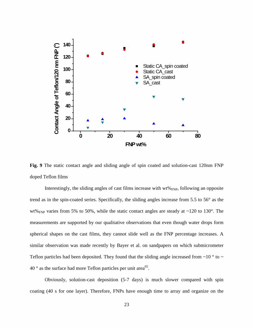
Fig. 9 The static contact angle and sliding angle of spin coated and solution-cast 120nm FNP
doped Teflon films
Interestingly, the sliding angles of cast films increase with wt%FNP, following an opposite
trend as in the spin-coated series. Specifically, the sliding angles increase from 5.5 to 56° as the
wt%FNP varies from 5% to 50%, while the static contact angles are steady at ~120 to 130°. The
measurements are supported by our qualitative observations that even though water drops form
spherical shapes on the cast films, they cannot slide well as the FNP percentage increases. A
similar observation was made recently by Bayer et al. on sandpapers on which submicrometer
Teflon particles had been deposited. They found that the sliding angle increased from ~10 ° to ~
40 ° as the surface had more Teflon particles per unit area65.
Obviously, solution-cast deposition (5-7 days) is much slower compared with spin
coating (40 s for one layer). Therefore, FNPs have enough time to array and organize on the

24
substrate in solution-cast deposition. In spin-coating, however, the mobility of FNPs is
prohibited because of the fast evaporation of solvent. In our case, the boiling point of the spin
solvent is very low (b.p FC-72 = 56 °C, at 1 atm), which means its evaporation is much faster in
the open air than in the half-sealed containers.
(a) (b)
Fig. 10 SEM images and of (a) spin-coat and (b) solution-cast deposited films with 70% (wt%)
120nm FNP.

25
4.0 CONCLUSION
We have demonstrated an easy and fast approach to prepare hydrophobic surfaces. For
the first time, Teflon AF 2400 was spin-coated on glass slides with FNPs (diameter 120, 310 and
510 nm). The degree of wetting is a function of the weight percentage of particles. Specifically,
we found that increasing the wt%FNP from 5% to 70% benefits the surface structure in a way that
the degree of wetting can be modulated with flexibility. The influence of particle size was found
less significant than what was seen previously50. The random piles of particles of the three sizes
are probably on average geometrically similar. Superhydrophobic states were achieved on spin-
coated films with 70% weight percent 510 nm FNPs.
Teflon AF 2400 introduces low surface energy and increased surface durability in
comparison to particle-only counterparts46,50. Moreover, the surface hydrophobicity on our
Teflon AF films is solely attributable to the hierarchical roughness created by FNPs and the
method of application. This approach does not depend on the underlying material structure54-59.
Furthermore, we showed that spin-coated Teflon AF surfaces have smaller sliding angles than
those fabricated by solution cast deposition, as a result of the restricted mobility of the FNPs in
the spinning process. This work provides a simple approach to superhydrophobic painting with
Teflon AF-containing FNP suspensions.

26
ACKNOWLEDGEMENT
We thank PPG Industries (PA), Glass Business and Discovery Center for help on the AFM.

27
BIBLIOGRAPHY
(1) Roach, P.; Shirtcliffe, N. J.; Newton, M. I. Soft Matter 2007, 4, 224. (2) Lafuma, A.; Quere, D. Nature materials 2003, 2, 457. (3) Ma, M.; Hill, R. M. Current Opinion in Colloid & Interface Science 2006, 11, 193. (4) Neinhuis, C.; Barthlott, W. Annals of Botany 1997, 79, 667. (5) Marmur, A. Langmuir 2004, 20, 3517. (6) Cao, L.; Jones, A. K.; Sikka, V. K.; Wu, J.; Gao, D. Langmuir 2009, 25, 12444. (7) Zhang, X.; Shi, F.; Niu, J.; Jiang, Y.; Wang, Z. Journal of Materials Chemistry 2008, 18, 621. (8) Cassie, A.; Baxter, S. Transactions of the Faraday Society 1944, 40, 546. (9) Yoshimitsu, Z.; Nakajima, A.; Watanabe, T.; Hashimoto, K. Langmuir 2002, 18, 5818. (10) Ming, W.; Wu, D.; van Benthem, R.; With, G. d. Nano Letters 2005, 5, 2298. (11) Zhai, L.; Cebeci, F. Ç.; Cohen, R. E.; Rubner, M. F. Nano Letters 2004, 4, 1349. (12) Fürstner, R.; Barthlott, W.; Neinhuis, C.; Walzel, P. Langmuir 2005, 21, 956. (13) Öner, D.; McCarthy, T. J. Langmuir 2000, 16, 7777. (14) Zhang, Y.; Lo, C.-W.; Taylor, J. A.; Yang, S. Langmuir 2006, 22, 8595. (15) Nosonovsky, M.; Bhushan, B. Nano Letters 2007, 7, 2633. (16) Ming, W.; Wu, D.; van Benthem, R.; de With, G. Nano Letters 2005, 5, 2298. (17) Qian, Z.; Zhang, Z.; Song, L.; Liu, H. Journal of Materials Chemistry 2009, 19, 1297. (18) Leng, B.; Shao, Z.; de With, G.; Ming, W. Langmuir 2009, 25, 2456. (19) Lin, P.-C.; Yang, S. Soft Matter 2009, 5, 1011. (20) Stöber, W.; Fink, A.; Bohn, E. Journal of colloid and interface science 1968, 26, 62. (21) Hench, L. L.; West, J. K. Chemical Reviews 1990, 90, 33. (22) Green, D.; Lin, J.; Lam, Y. F.; Hu, M. Z. C.; Schaefer, D. W.; Harris, M. Journal of colloid and interface science 2003, 266, 346. (23) Tsai, H.-J.; Lee, Y.-L. Langmuir 2007, 23, 12687. (24) Karunakaran, R. G.; Lu, C. H.; Zhang, Z.; Yang, S. Langmuir 2011, 27, 4594. (25) Ling, X. Y.; Phang, I. Y.; Vancso, G. J.; Huskens, J.; Reinhoudt, D. N. Langmuir 2009, 25, 3260. (26) Ogihara, H.; Xie, J.; Saji, T. Colloids and Surfaces A: Physicochemical and Engineering Aspects 2013.

28
(27) Wallqvist, V.; Claesson, P. M.; Swerin, A.; Östlund, C.; Schoelkopf, J.; Gane, P. A. C. Langmuir 2009, 25, 9197. (28) Wenzel, R. N. Ind. Eng. Chem 1936, 28, 988. (29) Wang, B.; Zhang, Y.; Shi, L.; Li, J.; Guo, Z. Journal of Materials Chemistry 2012. (30) Quéré, D. Nature materials 2002, 1, 14. (31) Bico, J.; Thiele, U.; Quéré, D. Colloids and Surfaces A: Physicochemical and Engineering Aspects 2002, 206, 41. (32) Gladysz, J. A.; Curran, D. P.; Horvath, I. T. Handbook of fluorous chemistry; Wiley-VCH, 2006. (33) Hildebrand, J. H.; Scott, R. L. 1955. (34) Goss, K.-U.; Bronner, G. The Journal of Physical Chemistry A 2006, 110, 9518. (35) O’Neal, K. L.; Zhang, H.; Yang, Y.; Hong, L.; Lu, D.; Weber, S. G. Journal of Chromatography A 2010, 1217, 2287. (36) Kiss, L. E.; Kövesdi, I.; Rábai, J. Journal of fluorine chemistry 2001, 108, 95. (37) Studer, A.; Hadida, S.; Ferritto, R.; Kim, S. Y.; Jeger, P.; Wipf, P.; Curran, D. P. Science 1997, 275, 823. (38) Luo, Z.; Zhang, Q.; Oderaotoshi, Y.; Curran, D. P. Science 2001, 291, 1766. (39) Curran, D.; Lee, Z. Green Chemistry 2001, 3, G3. (40) Curran, D. P. Pure and Applied Chemistry 2000, 72, 1649. (41) Curran, D. P.; Oderaotoshi, Y. Tetrahedron 2001, 57, 5243. (42) Chhatre, S. S.; Guardado, J. O.; Moore, B. M.; Haddad, T. S.; Mabry, J. M.; McKinley, G. H.; Cohen, R. E. Fluoroalkylated silicon-containing surfaces-Estimation of solid surface energy, DTIC Document, 2010. (43) Zhou, H.; Wang, H.; Niu, H.; Gestos, A.; Wang, X.; Lin, T. Advanced Materials 2012. (44) Saleema, N.; Sarkar, D.; Gallant, D.; Paynter, R.; Chen, X. G. ACS Applied Materials & Interfaces 2011, 3, 4775. (45) Campos, R.; Guenthner, A. J.; Haddad, T. S.; Mabry, J. M. Langmuir 2011, 27, 10206. (46) Brassard, J. D.; Sarkar, D.; Perron, J. Applied Sciences 2012, 2, 453. (47) Jisr, R. M.; Rmaile, H. H.; Schlenoff, J. B. Angewandte Chemie International Edition 2005, 44, 782. (48) Akram Raza, M.; Kooij, E. S.; van Silfhout, A.; Poelsema, B. Langmuir 2010, 26, 12962. (49) Lau, K. K. S.; Bico, J.; Teo, K. B. K.; Chhowalla, M.; Amaratunga, G. A. J.; Milne, W. I.; McKinley, G. H.; Gleason, K. K. Nano Letters 2003, 3, 1701. (50) Brassard, J. D.; Sarkar, D.; Perron, J. ACS Applied Materials & Interfaces 2011, 3, 3583. (51) Nilsson, M. A.; Daniello, R. J.; Rothstein, J. P. Journal of Physics D: Applied Physics 2010, 43, 045301. (52) Singh, E.; Chen, Z.; Houshmand, F.; Ren, W.; Peles, Y.; Cheng, H. M.; Koratkar, N. Small 2013, 9, 75. (53) Zhang, H.; Hussam, A.; Weber, S. G. Journal of the American Chemical Society 2010, 132, 17867.

29
(54) Kannarpady, G. K.; Khedir, K. R.; Ishihara, H.; Woo, J.; Oshin, O. D.; Trigwell, S.; Ryerson, C.; Biris, A. S. ACS Appl. Mater. Interfaces 2011, 3, 2332. (55) Thieme, M.; Blank, C.; Pereira, d. O. A.; Worch, H.; Frenzel, R.; Hoehne, S.; Simon, F.; Lewis, H. G. P.; White, A. J. Contact Angle, Wettability Adhes. 2009, 6, 251. (56) Wu, J.; Xia, J.; Lei, W.; Wang, B.-p. Mater. Lett. 2010, 65, 477. (57) An, T.; Cho, S. J.; Choi, W.; Kim, J. H.; Lim, S. T.; Lim, G. Soft Matter 2011, 7, 9867. (58) Kolomytkin, D. O.; Gallyamov, M. O.; Khokhlov, A. R. Russ. J. Phys. Chem. B 2011, 5, 1106. (59) Lifton, V. A.; Simon, S. J. Porous Mater. 2011, 18, 535. (60) Han, D.; Steckl, A. J. Langmuir 2009, 25, 9454. (61) Muthiah, P.; Hsu, S.-H.; Sigmund, W. Langmuir 2010, 26, 12483. (62) Scheffler, R.; Bell, N. S.; Sigmund, W. J. Mater. Res. 2010, 25, 1595. (63) Liu, Y.; Chen, X.; Xin, J. H. Nanotechnology 2006, 17, 3259. (64) Liu, Y.; Chen, X.; Xin, J. H. J. Mater. Chem. 2009, 19, 5602. (65) Bayer, I. S.; Brandi, F.; Cingolani, R.; Athanassiou, A. Colloid and Polymer Science 2013, 291, 367. (66) Chang, J. F.; Sun, B.; Breiby, D. W.; Nielsen, M. M.; Sölling, T. I.; Giles, M.; McCulloch, I.; Sirringhaus, H. Chemistry of materials 2004, 16, 4772. (67) Bao, Z.; Dodabalapur, A.; Lovinger, A. J. Applied Physics Letters 1996, 69, 4108. (68) Wang, G.; Swensen, J.; Moses, D.; Heeger, A. J. Journal of applied physics 2003, 93, 6137. (69) Ogihara, H.; Xie, J.; Okagaki, J.; Saji, T. Langmuir 2012, 28, 4605. (70) Oudrhiri-Hassani, F.; Presmanes, L.; Barnabé, A.; Tailhades, P. Applied Surface Science 2008, 254, 5796. (71) Hansson, P. M.; Skedung, L.; Claesson, P. M.; Swerin, A.; Schoelkopf, J.; Gane, P. A. C.; Rutland, M. W.; Thormann, E. Langmuir 2011, 27, 8153. (72) Nakae, H.; Inui, R.; Hirata, Y.; Saito, H. Acta materialia 1998, 46, 2313. (73) Fritzen-Garcia, M. B.; Zanetti-Ramos, B. G.; de Oliveira, C. S.; Soldi, V.; Pasa, A. A.; Creczynski-Pasa, T. B. Materials Science and Engineering: C 2009, 29, 405. (74) Bico, J.; Marzolin, C.; Quéré, D. EPL (Europhysics Letters) 1999, 47, 220.