thermostatic regulator for hot water recirculation
TRANSCRIPT
116 thermostatic regulator for
hot water recirculation

116 thermostatic regulator for hot water recirculation
1
Introduction
The Altecnic thermostatic regulator for domestic hot water re-circulation systems automatically maintains the specified water temperature.
Function
The thermostatic regulator is intended to be installed in the return pipe of each re-circulation circuit, automatically maintaining the specified water temperature.
The regulator controls the flow rate in accordance with the inlet water temperature by means of a dedicated internal thermostatic cartridge.
When the water temperature approaches the set value, the obturator progressively close and reduces the flow passage reducing the amount of water re-circulating.
The water supplied by the re-circulation pump is available to be distrubuted to other branches in the system, resulting in effective automatic thermal balancing.
The regulator is equipped with a thermal disinfection function, which is useful if the water temperature exceeds 55 to 60˚C
Product Range
116240 ½” regulator with temp. gauge and disinfection cartridge 116250 ¾” regulator with temp. gauge and disinfection cartridge 116260 1” regulator with temp. gauge and disinfection cartridge 116270 1¼” regulator with temp. gauge and disinfection cartridge
116140 ½” regulator with probe pocket for temperature gauge 116150 ¾” regulator with probe pocket for temperature gauge 116160 1” regulator with probe pocket for temperature gauge 116170 1¼” regulator with probe pocket for temperature gauge
Materials
Component Material Grade Body DZR BS EN 12165 CW724R Adjustable cartridge PSU polymer Seals Elastomer EPDM Adjustment knob ABS polymer Springs Stainless steel BS EN 10270-3
AISI 302
Technical Specification
Medium: Potable water Kv maximum: 1.8 m3/h Kv disinfection: 1.0 m3/h Kv min at 58°C (DN 15): 0.10 ± 20% m3/h Kv min at 58°C (DN 20): 0.12 ± 20% m3/h Kv (Dt = 5K): 0.45 m3/h Max. working pressure: 16 bar Max. differential pressure: 1 bar Temperature adjustment range: 35 to 60˚C Factory setting: 52˚C Disinfection temperature: 70˚C Closing temperature: 75˚C Connections - female: BS EN 10226-1
Dimensions
Operating Principle
In domestic hot water distribution circuits, to achieve systems requirements for the prevention of Legionella growth, it is essential to ensure that all circuits are kept at the correct temperature.
The re-circulation network must be balanced, to avoid non-uniform temperature distribution.
The thermostatic regulator, installed on each branch of the re-circulation circuit, automatically maintains the set temperature.
The regulator modulates the water flow rate in accordance with the inlet temperature by means of the action of a dedicated internal thermostatic cartridge.
When the water temperature approaches the set value, the obturator progressively reduces the passage.
The water flow rate supplied by the re-circulation pump is thus distributed to the other network branches, resulting in effective automatic thermal balancing.
Regulators 116240, 116250, 116260 and 116270 are already equipped with a thermal disinfection function, which is useful if the system temperature is to be increased to values over 55 to 60˚C.
This function can be completely automatic, activated by a dedicated second thermostatic cartridge that trips at 70˚C, or controlled with a control unit by means of a thermo-electric actuator.
Code A B C D E
116140 Rp½ 100 18.5 35 9116150 Rp¾ 100 18.5 35 9116160 Rp1 115 26.5 38 11116170 Rp1¼ 115 26.5 38 11116240 with gauge Rp½ 100 18.5 35 9116250 with gauge Rp¾ 100 18.5 35 9116260 with gauge Rp1 100 18.5 35 9116270 with gauge Rp1¼ 100 18.5 35 9
Code F G H J
116140 74.5116150 74.5116160 110.5116170 110.5116240 with gauge 74.5 27 63.5 41116250 with gauge 74.5 27 63.5 41116260 with gauge 110.5 21.5 71 41116270 with gauge 110.5 21.5 71 41
A
B
A
G
D E
FC
H
ØJ

116 thermostatic regulator for hot water recirculation
2
Construction - 116240, 116250, 116260 and 116270 with cartridge for disinfection and temperature gauge
Regulating Characteristics
Kvmax
T (˚C)
G (m3/h)
Kvdis
Kvmin
Disinfection termperatureB
Control temperatureA
40
60
65
70
75
80
85
90
Automatic DisinfectionC
1
2
3
4
Tset
5
Operation
Function A - Temperature Control
On reaching the set temperature, the obturator (1), governed by the thermostatic sensor (2), modulates the closure of the hot water outlet (3), thereby aiding circulation towards the other connected circuits. If the temperature decreases, there is the opposite action and the passage reopens, so as to ensure that all the branches of the system reach the required temperature. The characteristic curve of the valve is shown in curve A.
The graph shows the variation of the Kv value depending on the device configuration (A, B, C) and on the inlet temperature of the domestic hot water.
Function A - Temperature control
Kvmax (m3/h) = 1.8
Function B - Thermostatic thermal disinfection
Kvdis (m3/h) = 1 (maximum flow rate for a disinfection process with a temperature of 70˚C)
Kvmin (m3/h) = 0.2 (minimum flow rate with the module of the main regulator closed)
Function C - Controlled thermal disinfection
Kvdis (m3/h) = 1 (flow rate through the valve by means of a cartridge with thermo-electric actuator, with by-pass completely open)
Function B - Thermostatic Thermal Disinfection
The characteristic curve of operation B is the same as curve A until a temperature higher than about 68˚C is reached.
At this value the second thermostatic sensor (4) intervenes with the aim of controlling the disinfection process, allowing circulation independently of the action of the first thermostat.
This allows a passage of medium through a special by-pass (5), opening a passage up to the temperature of 70˚C.
If the temperature rises beyond this value, the flow through the by-pass circuit is reduced so as to allow thermal balancing to be performed even during the disinfection process. When it reaches about 75˚C, the regulator reduces the orifice so as not to circulate water at a high temperature, to avoid possible problems in the system. The characteristic curve of the valve is shown in curve A+B.
Temperature Gauge - Code 116010
Scale: 0 to 80˚C Diameter: Ø 40 mmStem diameter: Ø 9mm
1 Control temperature position open
1
2
3
2 Minimum position open
1
5
4
3 Disinfection flow path
Cartridge forwater
regulation
Cartridge fordisinfection
Temperaturegauge
Adjustmentknob
5
31
2
4

116 thermostatic regulator for hot water recirculation
3
Function C - Controlled Thermal Disinfection
The characteristic curve of operation C is the same as curve A until the temperature of intervention of the electronic disinfection system is reached.
At this value (which is controlled by a dedicated thermostat or electronic system), the thermo-electric actuator 656 series intervenes with the aim of controlling the disinfection process, allowing circulation independently of the action of the first thermostat, by means of a dedicated by-pass. In this case, the minimum head loss is produced during thermal disinfection against Legionella. The characteristic curve of the valve is shown in curve A+C.
Construction Details
DZR Alloy with very low lead contents
The material used to make the regulator body is perfectly in line with the new normative provision concerning contact with potable water. This is an innovative alloy with very low lead contents and dezincification resistant properties.
1 2
3
Fitting the Electric Actuator
To transform code 116140/50 into controlled mode it is sufficient to remove the plug (1) and screw on the cartridge code 116000 in its place (2). In this application, any 656 series thermo-electric actuator can be used.
The regulator can be equipped with a temperature gauge for measuring and controlling the temperature of the hot water in the circuit, code 116010 (3).
The temperature gauge pocket can also be used for inserting a special immersion probe (with Ø< 10 mm) for remote control of thedisinfection temperature by adedicated control unit.
This system allows disinfection control in each circuit and optimization of the disinfection process.
In this case it is possible to measure and monitor the water temperature in each circuit, even from remote.
230 V 50 HzThermal DisinfectionControl Unit
Certification
The thermostatic regulator complies with the performance requirements of product specification W554, applicable according to the provisions on system standards W551 for the prevention of Legionnaires’ disease.
It is also certified by WRAS in the UK.
The thermostatic regulator is made from materials certified for contact with drinking water, for use in the distribution circuits of water for human consumption.
4 Closed position during disinfection
5 Electrical controlled disinfection
116 thermostatic regulator for hot water recirculation
4
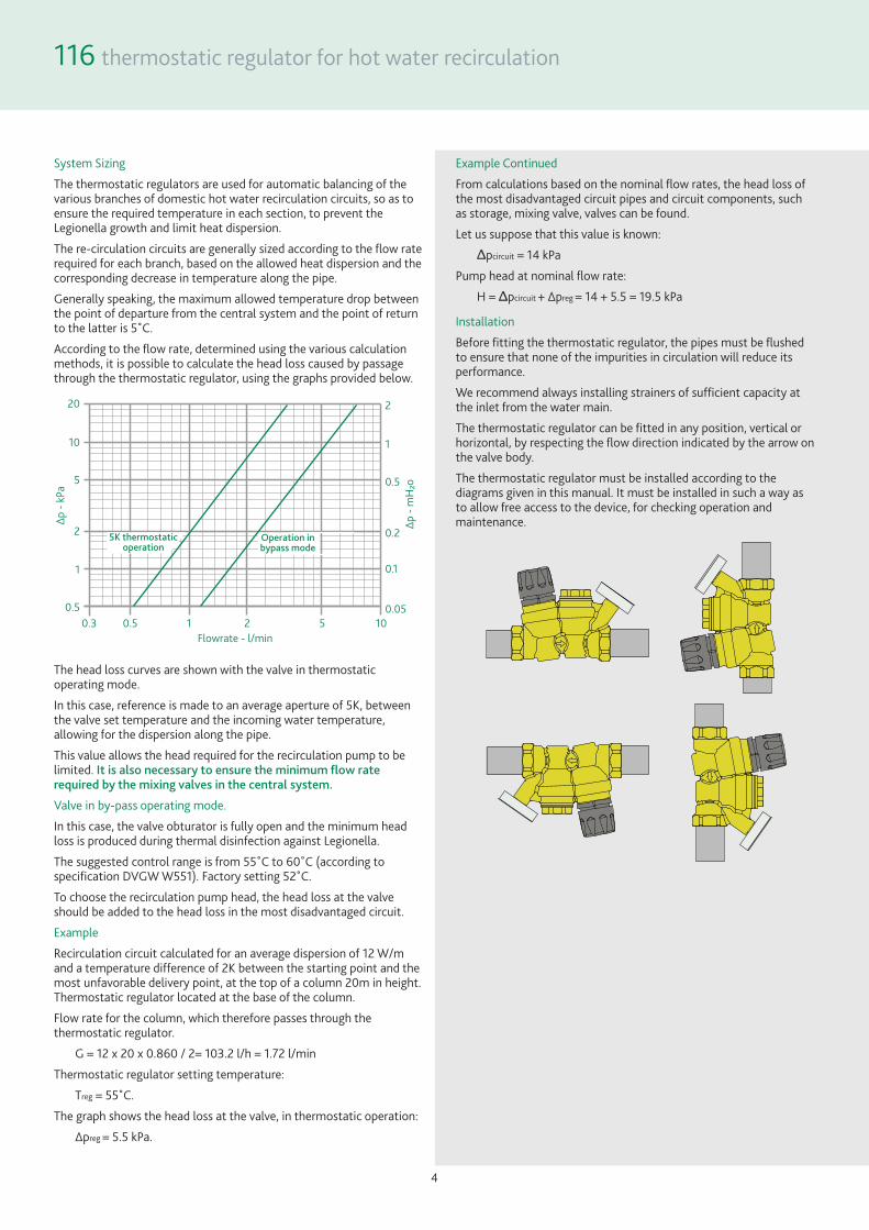
System Sizing
The thermostatic regulators are used for automatic balancing of the various branches of domestic hot water recirculation circuits, so as to ensure the required temperature in each section, to prevent the Legionella growth and limit heat dispersion.
The re-circulation circuits are generally sized according to the flow rate required for each branch, based on the allowed heat dispersion and the corresponding decrease in temperature along the pipe.
Generally speaking, the maximum allowed temperature drop between the point of departure from the central system and the point of return to the latter is 5˚C.
According to the flow rate, determined using the various calculation methods, it is possible to calculate the head loss caused by passage through the thermostatic regulator, using the graphs provided below.
20
10
5
2
1
0.5
Δp
- k
Pa
2
1
0.5
0.2
0.1
0.05
Δp
- m
H²o
0.3 0.5 1 2 5 10
Flowrate - l/min
Operation inbypass mode
5K thermostaticoperation
The head loss curves are shown with the valve in thermostatic operating mode.
In this case, reference is made to an average aperture of 5K, between the valve set temperature and the incoming water temperature, allowing for the dispersion along the pipe.
This value allows the head required for the recirculation pump to be limited. It is also necessary to ensure the minimum flow rate required by the mixing valves in the central system.
Valve in by-pass operating mode.
In this case, the valve obturator is fully open and the minimum head loss is produced during thermal disinfection against Legionella.
The suggested control range is from 55˚C to 60˚C (according to specification DVGW W551). Factory setting 52˚C.
To choose the recirculation pump head, the head loss at the valve should be added to the head loss in the most disadvantaged circuit.
Example
Recirculation circuit calculated for an average dispersion of 12 W/m and a temperature difference of 2K between the starting point and the most unfavorable delivery point, at the top of a column 20m in height. Thermostatic regulator located at the base of the column.
Flow rate for the column, which therefore passes through the thermostatic regulator.
G = 12 x 20 x 0.860 / 2= 103.2 l/h = 1.72 l/min
Thermostatic regulator setting temperature:
Treg = 55˚C.
The graph shows the head loss at the valve, in thermostatic operation:
Δpreg = 5.5 kPa.
Example Continued
From calculations based on the nominal flow rates, the head loss of the most disadvantaged circuit pipes and circuit components, such as storage, mixing valve, valves can be found.
Let us suppose that this value is known:
Δpcircuit = 14 kPa
Pump head at nominal flow rate:
H = Δpcircuit + Δpreg = 14 + 5.5 = 19.5 kPa
Installation
Before fitting the thermostatic regulator, the pipes must be flushed to ensure that none of the impurities in circulation will reduce its performance.
We recommend always installing strainers of sufficient capacity at the inlet from the water main.
The thermostatic regulator can be fitted in any position, vertical or horizontal, by respecting the flow direction indicated by the arrow on the valve body.
The thermostatic regulator must be installed according to the diagrams given in this manual. It must be installed in such a way as to allow free access to the device, for checking operation and maintenance.

116 thermostatic regulator for hot water recirculation
5
Maintenance
Both the adjustment cartridge and the disinfection control cartridge can be removed from the valve body for checking, cleaning or replacement.
Temperature Adjustment
The temperature is set at the desired value by turning the upper screw with the special knob.
The graduated scale shows the temperatures at which the indicator can be set.
It is recommended to set the valve temperature at a value about 5K greater than the water temperature at the valve inlet, taking into account the heat losses along the line, to limit the head required at the recirculation pump.
Take care to ensure the minimum flow rate at the mixing valves in the central heating system.
Adjustment Locking
After adjusting the temperature, the setting can be locked at the desired value using the control knob.
For this purpose, unscrew the locking screw at the top of the control knob, remove the knob and then put it back on so that the internal reference couples with the protrusion on the knob holder nut.
When locked, the indication of the temperature value on the knob is lost.
To restore it, completely unscrew the regulating headwork counter-clockwise. Reposition the knob on MAX value. Tighten the locking screw.
Accessories
Insulation Shell - Product Code CBN116140
Technical Specification
Material: closed cell expanded PE-X Thickness: min 13mm - max 23mm Density: inner part 30 kg/m3
outer part 80 kg/m3 Thermal conductivity (EN 12667): - at 0°C: 0.0345 W/(m-K)
- at 40°C: 0.0398 W/(m-K) Coefficient of resistance to water vapour diffusion: > 1.300 Working temperature range: 0 to 100˚C Fire behaviour (UNI 9177): class 1
Product code - thermo-electric actuator
116002 240V electric actuator
116004 24V electric actuator
Technical Specification
Normally closed ON/OFF: Electric supply: 230 V ac - 24 V ac Power consumption: 1.8 W Insulation: class II Protection class: IP 54 Ambient temperature range: 0 to 60˚C Operating time: 150 to 200 second Length of cable: 1 metre
Cartridge for use with electric actuator Product Code 116000
116 thermostatic regulator for hot water recirculation
6
1 12
1 12
1 12
1 12
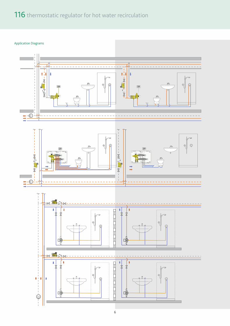
Application Diagrams

116 thermostatic regulator for hot water recirculation
Altecnic Ltd Mustang Drive, Stafford, Staffordshire ST16 1GW T: +44 (0)1785 218200 E: [email protected] Registered in England No: 2095101
altecnic.co.uk AL 305 17-12-20 E & O.E © Altecnic Limited. 2020 ALTECNIC™
©® Patents & Design Altecnic 2020 Altecnic Ltd retains all rights (including patents, designs and copyrights, trademarks and any other intellectual property rights) in relation to all information provided on or via the website, brochures or any other documents , including all texts, graphics and logos, contained on the website, in brochures or in any other documents published in the name of or on behalf of Altecnic Ltd in any form, without prior written consent of Altecnic Ltd.