thermo scientific hyperforma 5.1 single-use bioreactor (s ... · 1.4 bpc characteristics 28 1.4.1...
TRANSCRIPT
HyPerforma 5.1 Single-Use Bioreactor (S.U.B.) User’s Guide
DOC0022 • Revision FJuly 2019
ContentsWarnings, safety, and warranty information 1
How to use this guide 7
Chapter 1 HyPerforma Single‑Use Bioreactor (S.U.B.) overview 11
1.1 Introduction to the S.U.B. 12
1.2 Hardware characteristics 16
1.2.1 S.U.B. hardware components 16
1.2.2 S.U.B. system features 18
1.2.3 Additional system components 19
1.3 End user and third-party supplied components 26
1.3.1 pH and DO probes 26
1.3.2 Controllers 27
1.4 BPC characteristics 28
1.4.1 S.U.B. BPC components 28
1.4.2 S.U.B. BPC features 30
Chapter 2 Hardware assembly and setup 322.1 Initial installation preparation 33
2.1.1 Hardware shipment and setup 33
2.1.2 Hardware uncrating 33
2.1.3 Site preparation 33
2.2 Installation and setup 35
2.2.1 Preparing load cells 35
2.2.2 Leveling and connecting the system 36
2.2.3 Verifying drive shaft segments for 2,000 L systems 39
2.2.4 Setting the air pressure rate for motor lift
adjustment (1,000 L and 2,000 L systems only) 39
2.2.5 Using the handheld controller for motor lifts (1,000
L and 2,000 L systems only) 40
Chapter 3 Operating information 423.1 General system operating information 43
3.1.1 BPC preparation 43
3.1.2 BPC handling instructions 43
3.1.3 BPC operating information 43

3.1.4 Hardware operating information 45
3.1.5 External data logging and control 48
3.2 BPC and drive shaft loading instructions for 50 L, 100 L,
and 250 L systems 49
3.2.1 Initial BPC loading steps for 50 L, 100 L, and 250 L
systems 49
3.2.2 Drive shaft insertion for 50 L, 100 L, and 250 L
systems 55
3.2.3 Final installation steps for 50 L, 100 L, and 250 L
systems 59
3.3 BPC and drive shaft loading instructions for 500 L and
1,000 L systems 62
3.3.1 Initial BPC loading steps for 500 L and 1,000 L
systems 62
3.3.2 Drive shaft insertion for 500 L and 1,000 L systems 68
3.3.3 Final installation steps for 500 L and 1,000 L systems 74
3.4 BPC and drive shaft loading, and condenser system
setup instructions for 2,000 L systems 77
3.4.1 Initial BPC loading steps for 2,000 L systems 77
3.4.2 Condenser system setup for 2,000 L systems 86
3.4.3 Drive shaft insertion for 2,000 L systems 97
3.4.4 Final installation steps for 2,000 L systems 103
3.5 Probe preparation and insertion 107
3.5.1 Preparation and sterilization 107
3.5.2 Making CPC AseptiQuik connections 108
3.5.3 Probe insertion 112
3.5.4 Probe calibration 114
3.6 Cell culture operating instructions 114
3.6.1 Operating conditions for cell culture applications 114
3.6.2 Checkpoints prior to media fill 115
3.6.3 Media fill 115
3.6.4 Agitation for units with electrical control panels 116
3.6.5 Agitation rate calculations 118
3.6.6 Drive shaft rotation 123
3.6.7 Temperature control 123
3.6.8 Sparging strategy 123
3.6.9 pH probe calibration 126
Contents
3.6.10 DO probe calibration 126
3.6.11 Checkpoints prior to inoculation 126
3.6.12 Cell inoculation 126
3.6.13 Volume scale up 127
3.6.14 In-process checkpoints 127
3.6.15 BPC sampling 128
3.6.16 Dispense and harvest 131
3.6.17 BPC disposal 131
3.6.18 S.U.B. shutdown 131
3.6.19 Preparation for the next run 132
3.7 Verification procedures 133
3.7.1 Mixing speed verification 133
3.7.2 Temperature controller verification 133
3.7.3 Pressure monitor verification (when present) 133
3.7.4 Load cell verification 133
Chapter 4 System features and specifications 1344.1 Hardware features 135
4.1.1 Design features for 50–250 L systems 135
4.1.2 Design features for 500 L systems 136
4.1.3 Design features for 1,000 L systems 137
4.1.4 Design features for 2,000 L systems 138
4.2 Hardware specifications 139
4.3 E-Box features 157
4.4 BPC specifications 158
4.5 Additional system component part numbers 170
Chapter 5 Maintenance and troubleshooting 1745.1 Maintenance 175
5.1.1 Routine maintenance 175
5.1.2 Preventive maintenance 175
5.2 Troubleshooting and frequently asked questions 177
5.2.1 Hardware operation issues 177
5.2.2 Cell culture operation issues 179
5.2.3 Sparging issues 180
5.2.4 Probe and connector issues 181
5.2.5 Other issues 182
Contents
Chapter 6 General ordering information 1846.1 Ordering instructions 185
6.2 Ordering/support contact information 185
6.3 Technical support 186
Appendices Appendix A—Installation of female electrical receptacle for units with AC motors and electrical control panels 187
Appendix B—Mettler Toledo IND331 display load cell calibration instructions 190
Appendix C—2,000 L S.U.B. agitator operation and maintenance guidelines 192
Appendix D—Drive shaft use log 193
Appendix E—Application enhancements for the
HyPerforma S.U.B. 194
Contents
Warnings, safety, and warranty information
Congratulations! You have purchased high-quality Thermo Scientific equipment. We have included safety information in this guide, based on our knowledge and experience. It is important, however, for you to work with your Safety Management personnel to ensure that this equipment is integrated into your safety practices. Please take some time to perform your own job safety analysis in order to identify and control each potential hazard.
WARNING: Read and understand this user's guide before operating the equipment.The Thermo Scientific™ HyPerforma™ Single-Use Bioreactor (S.U.B.) is designed to be operated under traditional eukaryotic cell culture conditions. A general understanding of bioreactor systems and their operation is important prior to using the system for the first time. Read and understand this user’s guide before operating; failure to do so could result in injury and potential loss of product.
WARNING: Hazardous voltage inside.The mixer motor, motor controller and control panel all have electrical components. There is a risk of electrical shock and injury. Disconnect power before opening electrical components. Service should be performed by certified personnel only.Thermo Fisher Scientific recommends using standard lockout procedures when working on electrical components. The main breaker on the electrical control panel (E-Box) may be locked out.
WARNING: Static electricity may build up in BPCs.• BioProcess Containers (BPCs) may act as insulators for
electrostatic charge. If electrostatic charge is transferred to a BPC, the charge may be stored in the BPC and/or the product inside. This phenomena varies by product and use; therefore, it is the sole responsibility of the end user to ensure a hazard assessment is conducted and the risk of electrostatic shock is eliminated.
• Where applicable, a product contact stainless steel coupler may be grounded to the frame to dissipate electrostatic build up from the material within a BPC. It is good practice to dissipate electrostatic buildup by grounding all BPCs prior to coming in contact with them. When working with BPCs, the use of nonconductive materials, such as nonconductive gloves, is recommended.
HyPerforma 5.1 Single‑Use Bioreactor User's Guide | 1Thermo Scientific
Warnings, safety, and warranty information
WARNING: Rotating parts—entanglement hazard.Rotating and moving parts, such as the motor mount for 1,000 L and 2,000 L systems, can cause injury. Keep hands away from moving parts during operation.• Do not operate this equipment unless the supplied guarding is in
place and properly functioning.• It is the responsibility of the end user to assess this equipment
and ensure that equipment and safeguards are in good working condition, and that all operators are trained and aware of entanglement hazards and associated protective devices, such as hazard signs and guarding.
WARNING: Use ladders and elevated platforms with caution.A few operations, such as loading a BPC into a large S.U.B., may require the use of a ladder or platform. Before use, ensure the ladder has been inspected and weight-rated for its user. When using a ladder or platform, be sure it is stable, maintain three points of contact, and make sure the steps are clean.
WARNING: Follow lockout/tagout procedures.To prevent injury, when servicing equipment, use your company's lockout/tagout procedures to isolate electrical, mechanical, pneumatic, hydraulic, chemical, thermal, gravitational, or any other potential energy and protect workers from the release of hazardous energy.
WARNING: Use caution with hazardous chemicals or materials.Personnel servicing equipment need to know the hazards of any chemicals or materials that may be present on or in the equipment. Use general hazard communication techniques such as Safety Data Sheets, labels, and pictograms to communicate any hazards.
WARNING: Potential confined space.Operators may enter larger S.U.B. systems. Evaluate this equipment against your confined space standards and procedures.
WARNING: Burst hazard—air under pressure.The S.U.B. BPC chamber is under slight pressure under normal operating conditions. Normal passive venting prevents any excess of pressure building up within the chamber. Chamber pressure and inlet line pressure should be monitored for proper settings.• Contents under pressure• Do not exceed 0.03 bar (0.5 psi) BPC pressure• Do not exceed 0.34 bar (5 psi) inlet pressure• Assure vent filter is properly positioned and working properly
Thermo Scientific
Warnings, safety, and warranty information
HyPerforma 5.1 Single‑Use Bioreactor User's Guide | 2
WARNING: Hot surface. Do not touch.The heating jacket is designed to heat the inner vessel wall. Under normal operating conditions, the motor will generate heat and could create hot surfaces.• Hot surface inside• Contact with surfaces may cause burns • Do not touch while in operation
WARNING: Pinch hazard.The motor lift on 1,000 L and 2,000 L S.U.B.s can be raised and lowered using the handheld controller. Caution should be used when changing the position of the motor to avoid pinching an operator or causing damage to the equipment or the BPC.
WARNING: The Thermo Scientific HyPerforma Single-Use Bioreactor may not be installed in a potentially explosive atmosphere as set forth in the applicable EU ATEX Directive.It is the responsibility of the end user to review and understand the potential dangers listed in the ATEX 2014/34/EU guidelines.
Protective earth grounding
Protective earth grounding must be verified prior to plugging the S.U.B. into any electrical outlet. Ensure the receptacle is properly earth grounded.
Environmental conditions• Operating: 17 to 27°C; 20 to 80% relative humidity, non-
condensing• Storage: -25 to 65°C• Installation category II (over voltage) in accordance with IEC 664• Altitude Limit: 2,000 meters
Electrical connectionsPower should be supplied by a non-GFCI 15 amp circuit. Ground faults occur when current is leaking somewhere, in effect, electricity is escaping to the ground. Electrocution can occur when the human body serves as the path for the leakage to the ground. A ground fault circuit interrupter (GFCI) senses the current flowing to the ground and switches off the power (trips the GFCI) in a fraction of a second at currents well below those that are considered dangerous. Due to the sensitivity of GFCIs to electrical leakage (a few mA), it is recommended that the S.U.B. NOT be plugged into a GFCI outlet.
Warnings, safety, and warranty information
Thermo Scientific HyPerforma 5.1 Single‑Use Bioreactor User's Guide | 3
Water jacket vessel information
S.U.B. hardware units with water jackets have been designed to be operated with water as the heat transfer medium, with temperatures not exceeding 50°C (122°F) under less than 1 MPa (150 psig) operating pressure. For the utmost safety it is recommended that the S.U.B. be operated at 75 psig or less.
Note: The S.U.B. BPC operating limits for temperature are 5 to 40°C. The internal pressure should not exceed 0.03 bar (0.5 psi). The water jacket is not required to be registered, inspected and stamped with the Code U symbol per section U-1(c)2(f) of the ASME Boiler and Pressure Vessel Code and/or European Pressure Equipment Directive (PED) 97/23/EC. Upon request, a Declaration of Conformity, PED Sound Engineering Practices can be made available.
Use of agitation speed governors and safety interlocks
Agitation speed governors set up on the bioreactor controller are used to limit the maximum mixing speed, according to pre-defined liquid volumes. Safety interlocks, which stop agitation when the volume in a S.U.B. drops below defined limits, and speed-based governors prevent damage to the drive shaft in the bioreactor. Agitation speed governors and safety interlocks typically prevent the hazardous conditions listed below.
• Operating the motor at any speed while loading the drive shaft• Operating the agitator when volumes are less than 20% of a
system’s working volume• Operating the agitator above recommended speeds based on
qualified power input to volume (P/V) thresholds
The hazardous conditions above must be avoided in order to ensure qualified reliability. Using safety interlocks and agitation speed governors eliminates the chance of human error, which could reduce system reliability. Both the amount of liquid in the vessel and the amount of power applied to the impeller have an impact on the applied deflection on the shaft. Excess deflection and/or mixer speed may damage the drive shaft.
For more information about using P/V and safety interlocks in2,000 L bioreactor systems, see section 3.6.5 of this publication.
Warnings, safety, and warranty information
Thermo Scientific HyPerforma 5.1 Single‑Use Bioreactor User's Guide | 4

Warranty information
Any warranties, if applicable, covering this equipment exclude: (a) normal wear and tear; (b) accident, disaster or event of force majeure; (c) your misuse, fault or negligence; (d) use of the equipment in a manner for which it was not designed; (e) causes external to the equipment such as, but not limited to, external puncturing, power failure or electrical power surges; (f) improper storage and handling of the equipment; (g) use of the equipment in combination with equipment or software that we did not supply; (h) equipment sold to you as ‘used’ products; (i) contact with improperly used or unapproved chemicals or samples; (j) installation, removal, use, maintenance, storage, or handling in an improper, inadequate, or unapproved manner, such as, but not limited to, failure to follow the documentation or instructions in the deliverables or related to the equipment, operation outside of stated environmental or other operational specifications, or operation with unapproved software, materials or other products; (k) manufacture in accordance with requirements you gave us; (l) installation of software or interfacing or use of the equipment in combination with software or products we have not approved; (m) use of the deliverables or any documentation to support regulatory approvals; (n) the performance, efficacy or compatibility of specified components; and (o) the performance of custom equipment or products or specified components or achievement of any results from the equipment, specified components or services within ranges desired by you even if those ranges are communicated to us and are described in specifications, a quote, or a statement of work. ADDITIONALLY, ANY INSTALLATION, MAINTENANCE, REPAIR, SERVICE, RELOCATION OR ALTERATION TO OR OF, OR OTHER TAMPERING WITH, THE EQUIPMENT PERFORMED BY ANY PERSON OR ENTITY OTHER THAN US WITHOUT OUR PRIOR WRITTEN APPROVAL, OR ANY USE OF REPLACEMENT PARTS WE HAVE NOT SUPPLIED, WILL IMMEDIATELY VOID AND CANCEL ALL WARRANTIES WITH RESPECT TO THE AFFECTED EQUIPMENT. IF THE EQUIPMENT IS TO BE USED IN THE UNITED STATES, WE MAY VOID YOUR WARRANTY IF YOU SHIP THE EQUIPMENT OUTSIDE OF THE UNITED STATES.
HyPerforma 5.1 Single‑Use Bioreactor User's Guide | 5Thermo Scientific
Warnings, safety, and warranty information
Use restrictions
You must use this equipment in accordance with our documentation and if applicable, with our other associated instructions, including without limitation, a “research use only” product label or “limited use” label license. This equipment is intended for research use or further manufacturing in bioprocessing applications and not for diagnostic use or direct administration into humans or animals, we do not submit the equipment for regulatory review by any governmental body or other organization, and we do not validate the equipment for clinical or diagnostic use, for safety and effectiveness, or for any other specific use or application.
Seismic guidance
The buyer of the equipment is responsible to ensure country specific codes and seismic values are assessed for suitability of equipment installation and safety at the designated site. In addition, it is the buyer’s responsibility to assess the building structure for the designated equipment to ensure correct seismic anchoring and tethering designs for both the equipment and facility. It is highly recommended that the buyer consult with a local, licensed third party architecture and engineering firm to provide the buyer with correct engineering analysis and stamped documentation prior to equipment installation at the facility. In addition the buyer will be responsible for rigging and anchoring of the equipment to a specified, fixed location. Thermo Fisher can assist with establishing compliant seismic anchoring and tethering designs for purchased equipment based on building and country codes upon request at an agreed upon fee.
It is also noted that movable equipment (i.e. non-fixed or caster mount) is exempt from seismic design requirements according to ASCE 7-16, Chapter 13, section 1.4. Although these units are exempt from the seismic design requirements of ASCE 7, it should be noted that such equipment is susceptible to overturning during a seismic event. Therefore, it is the responsibility of the buyer to address seismic safety for movable equipment at the designated facility.
HyPerforma 5.1 Single‑Use Bioreactor User's Guide | 6Thermo Scientific
Warnings, safety, and warranty information

How to use this guide
Scope of this publication
This user's guide contains information about the standard Thermo Scientific™ HyPerforma™ 5.1 S.U.B. systems, including hardware, components, product design verification methods, installation, operation and specifications. It is intended for use by people who may or may not have experience with Thermo Scientific systems, but who have some knowledge of bioproduction processes and large-scale mixing systems.
Document change information
Revision Date Section Change made Author
A 10/2016 -- Initial release S. Jelus/E. Hale
B 02/2017Warnings and
SafetyAdded pinch hazard and potential confined space warnings to Warnings and Safety information
E. Hale
B 02/2017Warnings and
SafetyAdded information about safety interlocks to Warnings and Safety information
S. Jelus
B 02/2017 2.2.4Added number information and photo of ends of mutiple-section drive shaft
S. Jelus/E. Hale
B 02/2017 3.6.4Added warning note about agitation rate and volume requirements, and the use of safety interlocks
S. Jelus/E. Hale
B 02/2017 5.1.2Added measurement to Table 5.1 for 2,000 L drive shafts and cross-reference to Appendix D
E. Hale
B 02/2017 3.4.3Added information about 2-piece drive shaft, a note about the position of impeller tubing inside the BPC, and serial number information and a photo of ends of multiple-section drive shafts
S. Jelus/E. Hale
B 02/2017 1.1Added information about and photo of the BPC bearing port cap label
E. Hale
B 02/2017 3.4.3Added a note about not pushing drive shaft straight into the assembly when loading
S. Jelus/E. Hale
B 02/2017 3.4.3Added information and Figure 3.102 to illustrate proper insertion of drive shaft
S. Jelus/E. Hale
B 02/2017 3.4Added 2,000 L BPC and drive shaft loading, and condenser system setup instructions
E. Hale
B 02/2017 4.2 Added 1,000 L and 2,000 L hardware specifications E. Hale
B 02/2017 4.2Added information about 2-piece drive shaft to 2,000 L specifications
S. Jelus/E. Hale
B 02/2017 4.2Added ceiling height requirements for 2-piece drive shaft and detail about mixing speed to 2,000 L specifications
E. Hale
B 02/2017 1.2.3 Added information about BPC lift for 2,000 L systems E. Hale
B 02/2017 4.3 Added drawing of 1,000 L electrical control panel E. Hale
Thermo Scientific
How to use this guide
HyPerforma 5.1 Single‑Use Bioreactor User's Guide | 7

Revision Date Section Change made Author
B 02/20171.2.3 and
2.2.6Added information about motor lift and handheld controller for 1,000–2,000 L systems
E. Hale
B 02/2017 2.2.5Added information about setting the air pressure rate for motor adjustment for 1,000–2,000 L systems
E. Hale
B 02/2017 3.6.5 Added Agitation Rate Calculations section to Chapter 3 E. Hale
B 02/2017 3.3 Added 1,000 L systems to 500 L BPC loading section E. Hale
B 02/2017 3.3.2 Added information about drive shaft serial numbers E. Hale
B 02/2017 1.2.1 Added drawing showing 2,000 L S.U.B. features E. Hale
B 02/2017 2.1.3 Added 1,000 L and 2,000 L electrical box preparation E. Hale
B 02/2017 Appendix CAdded Appendix C—2,000 L S.U.B. agitator operation and maintenance guidelines
S. Jelus/ E. Hale
B 02/2017 Appendix D Added Appendix D—Drive shaft use log E. Hale
B 02/2017 Chapter 4 Removed 5.1 S.U.B. Made-to-order table E. Hale
B 03/2017 3.4.3 Added image of 2,000 L 5.1 BPC hanging tag E. Hale
B 03/2017 1.2.3 Added drive shaft specifications table E. Hale
B 04/2017 Warnings and Safety Added explosive atmosphere (ATEX) warning E. Hale
B 04/2017 4.2Changed "Maximum Mixing Rate" to "Agitation Speed Range" in hardware specifications
E. Hale
C 05/2017 Chapter 4 Corrected drive shaft diameter for 500 L S.U.B. E. Hale
D 09/2017 3.6Added harmonics/cavitation graph and context about these operating parameters to agitation information
E. Hale
D 09/2017 5.2, 3.4Added a FAQ about excessive residue buildup in condenser bag due to low TCU coolant levels, and provided more information in the 2,000 L condenser system instructions
E. Hale
D 09/2017Warnings, safety, and warranty information
Added warranty and usage information E. Hale
D 09/2017 How to use this guide Added a section for abbreviations/acronyms E. Hale
D 09/2017 Chapter 4Added noise level to specifications for all S.U.B. sizes, and corrected 2,000 L ceiling height requirement for 4-piece drive shaft loading
E. Hale
D 09/2017 Chapter 4Added accessory part numbers, and BPC illustrations and specifications
E. Hale
D 10/2017 3.4.3 Added note that all 2,000 L drive shaft heads are now black E. Hale
D 01/2018 -- Updated warning symbols and "Hot surface" warning E. Hale
D 01/2018 4.2 Corrected 500 L ceiling height requirement for drive shaft loading E. Hale
D 01/2018 3.6.5Revised Graph 3.4 by changing 2,000 L line to 750 and 1,000 L line to 375 L
E. Hale
D 01/2018 3.6.5 Changed Table 3.4 footnote to "> 20 W/m3" E. Hale
D 01/2018 3.6.5 Changed first footnote in Table 3.6 to "> 20 W/m3" E. Hale
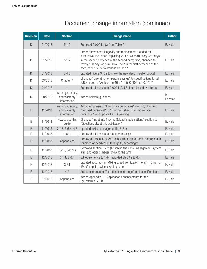
Document change information (continued)
How to use this guide
Thermo Scientific HyPerforma 5.1 Single‑Use Bioreactor User's Guide | 8
Revision Date Section Change made Author
D 01/2018 5.1.2 Removed 2,000 L row from Table 5.1 E. Hale
D 01/2018 5.1.2
Under "Drive shaft longevity and replacement," added "of cumulative use" after "replacing your drive shaft every 360 days." In the second sentence of the second paragraph, changed to "every 180 days of cumulative use." In the first sentence of the note, added "< 50% working volume."
E. Hale
D 01/2018 3.4.3 Updated Figure 3.102 to show the new deep impeller pocket E. Hale
D 03/2018 Chapter 4Changed "Operating temperature range" to specifications for all S.U.B. sizes to "Ambient to 40 +/- 0.5°C (104 +/- 0.9°C)"
E. Hale
D 04/2018 -- Removed references to 2,000 L S.U.B. four-piece drive shafts E. Hale
D 08/2018Warnings, safety,
and warranty information
Added seismic guidanceK. Leeman
E 11/2018Warnings, safety,
and warranty information
Added emphasis to "Electrical connections" section, changed "certified personnel" to "Thermo Fisher Scientific service personnel," and updated ATEX warning
E. Hale
E 11/2018How to use this
guideChanged "Input into Thermo Scientific publications" section to "Questions about this publication"
E. Hale
E 11/2018 2.1.3, 3.6.4, 4.3 Updated text and images of the E-Box E. Hale
E 11/2018 3.5.3 Removed references to metal probe clips E. Hale
E 11/2018 AppendicesRemoved Appendix B (AC-Tech variable speed drive settings) and renamed Appendices B through D, accordingly
E. Hale
E 11/2018 2.2.3, VariousRemoved section 2.2.3 (Attaching the cable management system arm) and edited images showing the arm
E. Hale
E 12/2018 3.1.4, 3.6.4 Edited sentence (3.1.4), reworded step #2 (3.6.4) E. Hale
E 12/2018 3.7.1Updated accuracy in "Mixing speed verification" to +/- 1.5 rpm or 1% of setpoint, whichever is greater
E. Hale
E 12/2018 4.2 Added tolerance to "Agitation speed range" in all specifications E. Hale
F 07/2019 AppendicesAdded Appendix E—Application enhancements for the HyPerforma S.U.B.
E. Hale
Document change information (continued)
Thermo Scientific
How to use this guide
HyPerforma 5.1 Single‑Use Bioreactor User's Guide | 9

Questions about this publication
If you have any questions or concerns about the content of this publication, please contact [email protected] and your Thermo Fisher Scientific sales team.
Related publicationsPlease contact your local sales representative for information about the related publications listed below.
Publication Description
Thermo Scientific HyPerforma 5.1 S.U.B. Validation Guide (DOC0023)
Information about validation procedures
Thermo Scientific HyPerforma 5.1 S.U.B. Data Sheets (for various sizes)
Product descriptions and ordering information
Thermo Scientific HyPerforma 5.1 S.U.B. Packing and Unpacking Guide (DOC0033)
Instructions for packing and unpacking equipment
Abbreviations/acronyms
Refer to the list below for definitions of the abbrieviations and acronyms used in this publication.
BPC BioProcess ContainercGMP Current good manufacturing practicesDO Dissolved oxygenETP Equipment Turnover PackageGFCI Ground fault circuit interrupterHMI Human machine interfaceID Inner diameterIEC International Electrical CodeOD Outer diameterPED Pressure Equipment DirectivePID Proportional integral derivativeP/V Power input to volumeRTD Resistance temperature detectorSTR Stirred tank reactorS.U.B. Single-Use BioreactorTCU Temperature control unitVFD Variable frequency drive
HyPerforma 5.1 Single‑Use Bioreactor User's Guide | 10Thermo Scientific
How to use this guide

HyPerforma Single-Use Bioreactor (S.U.B.) overview
Chapter contents1.1 Introduction to the S.U.B.1.2 Hardware characteristics1.3 End user and third-party supplied components1.4 BPC characteristics
1
Thermo Scientific HyPerforma 5.1 Single‑Use Bioreactor User's Guide | 11
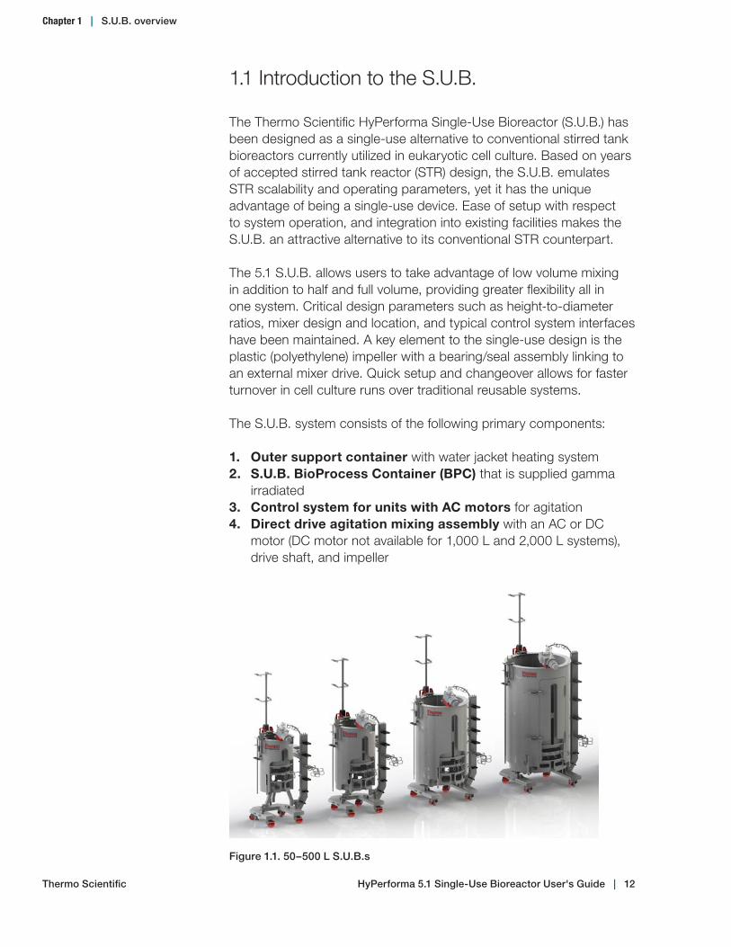
Figure 1.1. 50–500 L S.U.B.s
1.1 Introduction to the S.U.B.
The Thermo Scientific HyPerforma Single-Use Bioreactor (S.U.B.) has been designed as a single-use alternative to conventional stirred tank bioreactors currently utilized in eukaryotic cell culture. Based on years of accepted stirred tank reactor (STR) design, the S.U.B. emulates STR scalability and operating parameters, yet it has the unique advantage of being a single-use device. Ease of setup with respect to system operation, and integration into existing facilities makes the S.U.B. an attractive alternative to its conventional STR counterpart.
The 5.1 S.U.B. allows users to take advantage of low volume mixing in addition to half and full volume, providing greater flexibility all in one system. Critical design parameters such as height-to-diameter ratios, mixer design and location, and typical control system interfaces have been maintained. A key element to the single-use design is the plastic (polyethylene) impeller with a bearing/seal assembly linking to an external mixer drive. Quick setup and changeover allows for faster turnover in cell culture runs over traditional reusable systems.
The S.U.B. system consists of the following primary components:
1. Outer support container with water jacket heating system2. S.U.B. BioProcess Container (BPC) that is supplied gamma
irradiated3. Control system for units with AC motors for agitation4. Direct drive agitation mixing assembly with an AC or DC
motor (DC motor not available for 1,000 L and 2,000 L systems), drive shaft, and impeller
Chapter 1 | S.U.B. overview
Thermo Scientific HyPerforma 5.1 Single‑Use Bioreactor User's Guide | 12
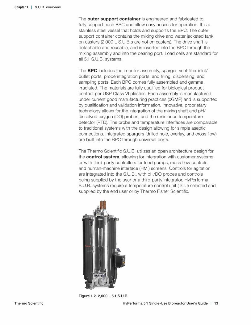
The outer support container is engineered and fabricated to fully support each BPC and allow easy access for operation. It is a stainless steel vessel that holds and supports the BPC. The outer support container contains the mixing drive and water jacketed tank on casters (2,000 L S.U.B.s are not on casters). The drive shaft is detachable and reusable, and is inserted into the BPC through the mixing assembly and into the bearing port. Load cells are standard for all 5.1 S.U.B. systems.
The BPC includes the impeller assembly, sparger, vent filter inlet/outlet ports, probe integration ports, and filling, dispensing, and sampling ports. Each BPC comes fully assembled and gamma irradiated. The materials are fully qualified for biological product contact per USP Class VI plastics. Each assembly is manufactured under current good manufacturing practices (cGMP) and is supported by qualification and validation information. Innovative, proprietary technology allows for the integration of the mixing shaft and pH/dissolved oxygen (DO) probes, and the resistance temperature detector (RTD). The probe and temperature interfaces are comparable to traditional systems with the design allowing for simple aseptic connections. Integrated spargers (drilled hole, overlay, and cross flow) are built into the BPC through universal ports.
The Thermo Scientific S.U.B. utilizes an open architecture design for the control system, allowing for integration with customer systems or with third-party controllers for feed pumps, mass flow controls, and human-machine interface (HMI) screens. Controls for agitation are integrated into the S.U.B., with pH/DO probes and controls being supplied by the user or a third-party integrator. HyPerforma S.U.B. systems require a temperature control unit (TCU) selected and supplied by the end user or by Thermo Fisher Scientific.
Figure 1.2. 2,000 L 5.1 S.U.B.
Chapter 1 | S.U.B. overview
Thermo Scientific HyPerforma 5.1 Single‑Use Bioreactor User's Guide | 13

Figure 1.3. Hanging tag on 50–500 L 5.1 BPC bearing port Figure 1.4. Close‑up view of 5.1 BPC hanging tag
Figure 1.6. Close‑up view of engraving on 5.1 motor mount
Figure 1.5. Engraving on 50–500 L 5.1 motor mount
This user’s guide covers the setup, operation, maintenance, and troubleshooting of all 5.1 S.U.B. systems in the following volumes: 50 L, 100 L, 250 L, 500 L, 1,000 L, and 2,000 L.
Figures 1.3–1.7 illustrate some of the standard labeling on 50 L, 100 L, 250 L, and 500 L 5.1 S.U.B. systems. Systems in these sizes include the following:
• Hanging tag labeled for 5:1 mixing attached to the BPC bearing port (Figures 1.3–1.4)
• Motor mount engraved with "5:1 Mixing" (Figures 1.5–1.6)• "Usable by 5:1 drive shaft only" warning label on BPC bearing port
cap (Figure 1.7) • Drive shaft with a black head that is engraved with "5:1 Mixing."
Chapter 1 | S.U.B. overview
Thermo Scientific HyPerforma 5.1 Single‑Use Bioreactor User's Guide | 14
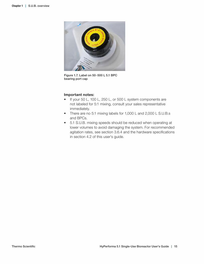
Important notes: • If your 50 L, 100 L, 250 L, or 500 L system components are
not labeled for 5:1 mixing, consult your sales representative immediately.
• There are no 5:1 mixing labels for 1,000 L and 2,000 L S.U.B.s and BPCs.
• 5.1 S.U.B. mixing speeds should be reduced when operating at lower volumes to avoid damaging the system. For recommended agitation rates, see section 3.6.4 and the hardware specifications in section 4.2 of this user's guide.
Figure 1.7. Label on 50–500 L 5.1 BPC bearing port cap
Thermo Scientific
Chapter 1 | S.U.B. overview
HyPerforma 5.1 Single‑Use Bioreactor User's Guide | 15
1.2 Hardware characteristics
1.2.1 S.U.B. hardware components
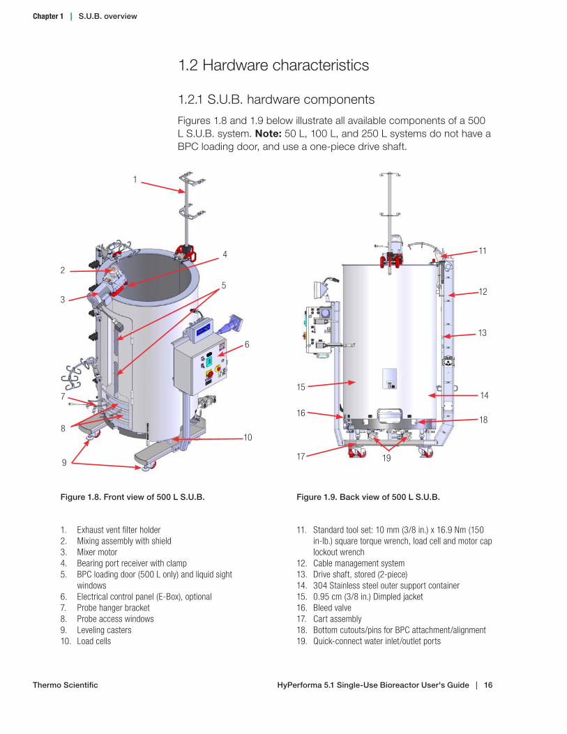
Figures 1.8 and 1.9 below illustrate all available components of a 500 L S.U.B. system. Note: 50 L, 100 L, and 250 L systems do not have a BPC loading door, and use a one-piece drive shaft.
1
2
3
4
5
6
7
8
9
10
Figure 1.8. Front view of 500 L S.U.B.
13
14
18
19
15
17
16
Figure 1.9. Back view of 500 L S.U.B.
11
12
1. Exhaust vent filter holder2. Mixing assembly with shield3. Mixer motor4. Bearing port receiver with clamp5. BPC loading door (500 L only) and liquid sight
windows6. Electrical control panel (E-Box), optional 7. Probe hanger bracket8. Probe access windows9. Leveling casters10. Load cells
11. Standard tool set: 10 mm (3/8 in.) x 16.9 Nm (150 in-lb.) square torque wrench, load cell and motor cap lockout wrench
12. Cable management system13. Drive shaft, stored (2-piece)14. 304 Stainless steel outer support container15. 0.95 cm (3/8 in.) Dimpled jacket 16. Bleed valve17. Cart assembly18. Bottom cutouts/pins for BPC attachment/alignment19. Quick-connect water inlet/outlet ports
Chapter 1 | S.U.B. overview
Thermo Scientific HyPerforma 5.1 Single‑Use Bioreactor User's Guide | 16
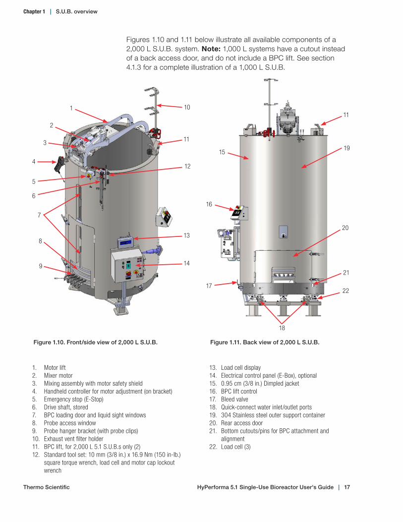
Figures 1.10 and 1.11 below illustrate all available components of a 2,000 L S.U.B. system. Note: 1,000 L systems have a cutout instead of a back access door, and do not include a BPC lift. See section 4.1.3 for a complete illustration of a 1,000 L S.U.B.
1. Motor lift2. Mixer motor3. Mixing assembly with motor safety shield4. Handheld controller for motor adjustment (on bracket)5. Emergency stop (E-Stop)6. Drive shaft, stored7. BPC loading door and liquid sight windows8. Probe access window9. Probe hanger bracket (with probe clips)10. Exhaust vent filter holder11. BPC lift, for 2,000 L 5.1 S.U.B.s only (2)12. Standard tool set: 10 mm (3/8 in.) x 16.9 Nm (150 in-lb.)
square torque wrench, load cell and motor cap lockout wrench
13. Load cell display14. Electrical control panel (E-Box), optional15. 0.95 cm (3/8 in.) Dimpled jacket16. BPC lift control17. Bleed valve18. Quick-connect water inlet/outlet ports19. 304 Stainless steel outer support container20. Rear access door21. Bottom cutouts/pins for BPC attachment and
alignment22. Load cell (3)
Figure 1.11. Back view of 2,000 L S.U.B.
20
21
15
17
19
11
18
16
22
Figure 1.10. Front/side view of 2,000 L S.U.B.
1
2
3 11
5
6
4
7
10
12
6
9
13
14
8
Chapter 1 | S.U.B. overview
Thermo Scientific HyPerforma 5.1 Single‑Use Bioreactor User's Guide | 17

1.2.2 S.U.B. system features
The S.U.B. is designed for system mobility and easy integration, and utilizes a straightforward operator interface. The following sections give general descriptions of S.U.B. hardware features.
AgitationIf your system uses an AC motor and a Thermo Scientific electrical control panel (E-Box), the stirring speed is adjusted by using the E-Box keypad interface. The agitation control interface utilizes a digital display to indicate stirring speed in units of revolutions per minute (rpm). Power is supplied to the motor by a two-position power switch. The up and down arrows on the agitation keypad adjust the stirring speed. If your 50 L, 100 L, 250 L, or 500 L system has a DC motor and is integrated and managed by a third-party controller, agitation is managed by the controller. Thermo Fisher Scientific does not provide electrical control for units with DC motors.
Bioreactor control systemThe S.U.B. is designed to integrate with existing bioreactor control systems in their numerous configurations. The S.U.B. control system supplied with the Thermo Scientific E-Box manages the agitation process parameters. Parameters of pH and DO, gas management, feed addition, and base addition control must be managed by an external controller supplied by the end user or a third-party integrator.
TemperatureThe S.U.B. can be operated within the temperature range from ambient to 40°C. The process temperature is measured by means of a supplied RTD (pt-100) that is inserted into the thermowell of the BPC. Water jacket system temperature control is maintained through the TCU.
Condenser systemThe condenser system is recommended for 2,000 L S.U.B. use, and is available as optional hardware for smaller systems. It cools exhaust gases and re-circulates condensate into the bioreactor.
Heating performanceHeating times for the S.U.B. systems vary based upon operating liquid volume and temperature, ambient or heating fluid temperature, sparger rate, and mixing rate. Users should adjust process liquid staging and seeding strategies to the unique aspects of the S.U.B. Process controllers are designed to provide optimum heat transfer and to minimize heat-up times while maintaining the material integrity of the polymer film construction of the BPC. Refer to section 3.1.4 for expected heating times.
Chapter 1 | S.U.B. overview
Thermo Scientific HyPerforma 5.1 Single‑Use Bioreactor User's Guide | 18

Table 1.1. Drive shaft specifications for 50–2,000 L systems.
System size
Overall shaft length
Number of pieces Head description Material
50 L 85.09 cm (33.5 in.) 1-pieceBlack, engraved with "5:1 Mixing"
Stainless steel or aluminum
100 L 100.58 cm (39.6 in.) 1-pieceBlack, engraved with "5:1 Mixing"
Stainless steel or aluminum
250 L 120.90 cm (47.6 in.) 1-pieceBlack, engraved with "5:1 Mixing"
Stainless steel or aluminum
500 L 155.7 cm (61.3 in.) 2-pieceBlack, engraved with "5:1 Mixing"
Stainless steel or aluminum
1,000 L 167.6 cm (66 in.)3-piece or 4-piece
White Stainless steel
2,000 L 215.6 cm (84.9 in.) 2-pieceBlack, engraved with drive shaft length
Carbon fiber
Probe integrationThe autoclave tray (Figure 1.12) holds the electrochemical probes and bellows in place during the autoclave sterilization process. Design elements include the following.• Fabricated from stainless steel• Features a plastic handle for easy transport right out of the
autoclave• Positions probes on 15% incline for greater probe/membrane
longevity• Will restrain probe bellows from collapsing during sterilization• Accommodates two probes
1.2.3 Additional system components
Drive shaftsThe drive shaft couples the mixing impeller that is inside the BPC to the motor. If you are using a 5.1 BPC, it is important to use the correct drive shaft. See Table 1.1 for drive shaft specifications for each S.U.B. size.
Chapter 1 | S.U.B. overview
Thermo Scientific HyPerforma 5.1 Single‑Use Bioreactor User's Guide | 19
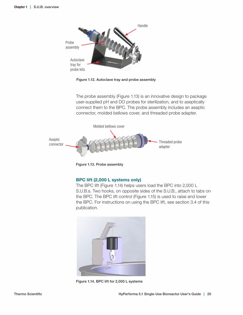
Figure 1.13. Probe assembly
Aseptic connector
Molded bellows cover
Threaded probe adapter
Probe assembly
Handle
Figure 1.12. Autoclave tray and probe assembly
Autoclave tray for probe kits
BPC lift (2,000 L systems only)The BPC lift (Figure 1.14) helps users load the BPC into 2,000 L S.U.B.s. Two hooks, on opposite sides of the S.U.B., attach to tabs on the BPC. The BPC lift control (Figure 1.15) is used to raise and lower the BPC. For instructions on using the BPC lift, see section 3.4 of this publication.
The probe assembly (Figure 1.13) is an innovative design to package user-supplied pH and DO probes for sterilization, and to aseptically connect them to the BPC. The probe assembly includes an aseptic connector, molded bellows cover, and threaded probe adapter.
Figure 1.14. BPC lift for 2,000 L systems
Chapter 1 | S.U.B. overview
Thermo Scientific HyPerforma 5.1 Single‑Use Bioreactor User's Guide | 20
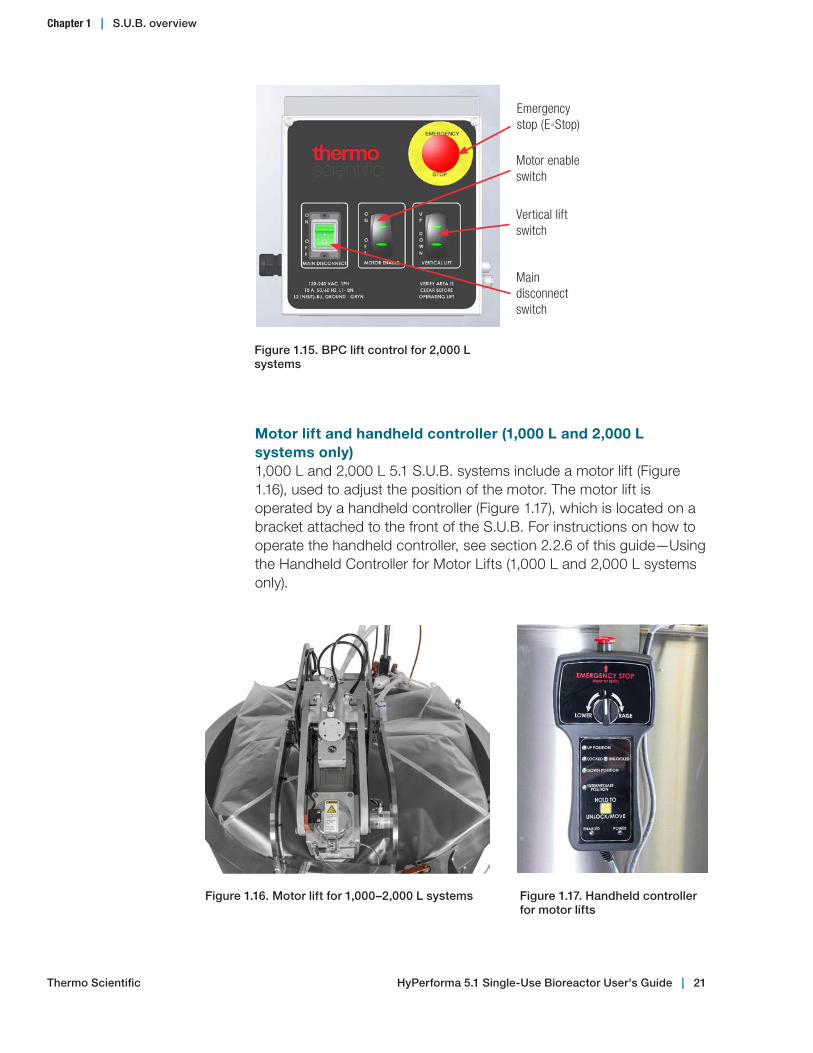
Motor lift and handheld controller (1,000 L and 2,000 L systems only)1,000 L and 2,000 L 5.1 S.U.B. systems include a motor lift (Figure 1.16), used to adjust the position of the motor. The motor lift is operated by a handheld controller (Figure 1.17), which is located on a bracket attached to the front of the S.U.B. For instructions on how to operate the handheld controller, see section 2.2.6 of this guide—Using the Handheld Controller for Motor Lifts (1,000 L and 2,000 L systems only).
Figure 1.17. Handheld controller for motor lifts
Figure 1.16. Motor lift for 1,000–2,000 L systems
Figure 1.15. BPC lift control for 2,000 L systems
Motor enable switch
Vertical lift switch
Main disconnect switch
Emergency stop (E-Stop)
Chapter 1 | S.U.B. overview
Thermo Scientific HyPerforma 5.1 Single‑Use Bioreactor User's Guide | 21
Load cellsLoad cells, which are used to determine the weight of the contents of a S.U.B., are installed on all standard 5.1 S.U.B. systems. Load cell retro-fit kits can also be added to existing S.U.B. units by a certified service technician. Load cells arrive uncalibrated. The load cell manufacturer or a qualified technician should calibrate these systems onsite.
The load cell kit comes with three load cells, summing block, wiring, and a display screen with a choice of several data interfaces (see Figure 1.19).
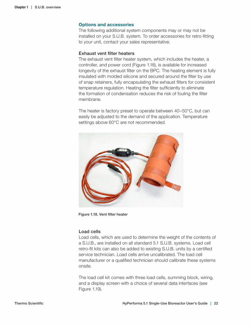
Figure 1.18. Vent filter heater
Options and accessoriesThe following additional system components may or may not be installed on your S.U.B. system. To order accessories for retro-fitting to your unit, contact your sales representative.
Exhaust vent filter heatersThe exhaust vent filter heater system, which includes the heater, a controller, and power cord (Figure 1.18), is available for increased longevity of the exhaust filter on the BPC. The heating element is fully insulated with molded silicone and secured around the filter by use of snap retainers, fully encapsulating the exhaust filters for consistent temperature regulation. Heating the filter sufficiently to eliminate the formation of condensation reduces the risk of fouling the filter membrane.
The heater is factory preset to operate between 40–50°C, but can easily be adjusted to the demand of the application. Temperature settings above 60°C are not recommended.
Chapter 1 | S.U.B. overview
Thermo Scientific HyPerforma 5.1 Single‑Use Bioreactor User's Guide | 22

Load cells are typically radial-mounted in sets of three. The mounting location (Figure 1.20) varies slightly for each size in order to allow easy access to the bottom drain or sparging mechanisms and tubing.
Figure 1.20. Load cell location
AC and DC motorsAC and DC motor options are available to help tailor the S.U.B. system to your specific needs. Note: DC motors are only available for 50 L, 100 L, 250 L, or 500 L systems.
DC motors operate at a lower voltage and, when integrated with a controller system that receives sensor feedback, provide more accurate speed control through a digital program transmitter. The DC motor comes with an encoder, but does not come with a motor control option from Thermo Scientific. For DC motors, a control option must be specified by the end user.
Figure 1.19. Load cell system overview
Chapter 1 | S.U.B. overview
Thermo Scientific HyPerforma 5.1 Single‑Use Bioreactor User's Guide | 23

Miscellaneous itemsThe miscellaneous items listed below are ancillary components that support the operation of the HyPerforma S.U.B. for cell culture production, and enhance the overall performance of the complete system.• Sampling manifold with luer lock• S.U.B. temperature sample port—For RTD calibration/
validation
Harvest line hook
Channels for sparge lines
Channels for feed and base addition lines
Figure 1.21. 500 L S.U.B. with cable management system
AC motors may be used with the Thermo Scientific E-Box. AC motors include a variable frequency drive, and are controlled using either the provided keypad or a controller specified by the end user.
Cable management systemsThe cable management system is available as an option on 50 L, 100 L, 250 L, 500 L, and 1,000 L units. It is used to organize various lines and includes the following components (Figure 1.21).• Internal channel for sparge lines• External channels for feed and base addition lines• Harvest line hook
Chapter 1 | S.U.B. overview
Thermo Scientific HyPerforma 5.1 Single‑Use Bioreactor User's Guide | 24

Figure 1.23. Heavy‑duty tubing clamps
• Heavy-duty tubing clamps (typically four or five)—Tubing clamps (Figure 1.23) are required for pinching off line sets that are not in use in order to prevent process fluids from moving into the line sets. Prior to sterile probe insertion, tubing clamps must be in place to close off probe ports. For more information, see the BPC and drive shaft loading instructions in sections 3.2, 3.3, and 3.4 of this publication.
Figure 1.22. Sparge line support
Note: The sparge line support is included with all standard S.U.B. units. Other items are sold separately. Please contact your sales representative for more information.
• Sparge line support—Keeps the drilled hole sparge line in a vertical position for optimal gas flow (Figure 1.22). For more information see section 2.2—Installation and Setup.
Chapter 1 | S.U.B. overview
Thermo Scientific HyPerforma 5.1 Single‑Use Bioreactor User's Guide | 25
1.3 End user and third-party supplied components
1.3.1 pH and DO probes
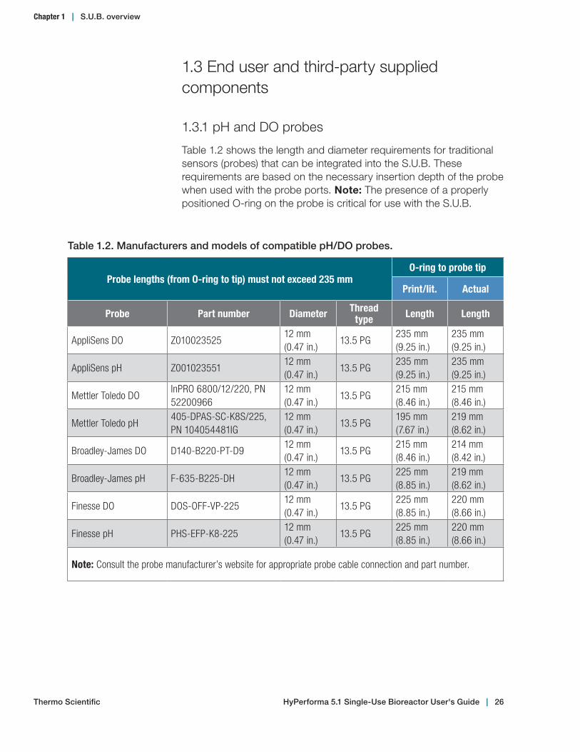
Table 1.2 shows the length and diameter requirements for traditional sensors (probes) that can be integrated into the S.U.B. These requirements are based on the necessary insertion depth of the probe when used with the probe ports. Note: The presence of a properly positioned O-ring on the probe is critical for use with the S.U.B.
Table 1.2. Manufacturers and models of compatible pH/DO probes.
Probe lengths (from O-ring to tip) must not exceed 235 mmO-ring to probe tip
Print/lit. Actual
Probe Part number Diameter Thread type Length Length
AppliSens DO Z01002352512 mm (0.47 in.)
13.5 PG235 mm (9.25 in.)
235 mm (9.25 in.)
AppliSens pH Z00102355112 mm (0.47 in.)
13.5 PG235 mm (9.25 in.)
235 mm (9.25 in.)
Mettler Toledo DOInPRO 6800/12/220, PN 52200966
12 mm (0.47 in.)
13.5 PG215 mm (8.46 in.)
215 mm (8.46 in.)
Mettler Toledo pH405-DPAS-SC-K8S/225, PN 104054481IG
12 mm (0.47 in.)
13.5 PG195 mm (7.67 in.)
219 mm (8.62 in.)
Broadley-James DO D140-B220-PT-D912 mm (0.47 in.)
13.5 PG215 mm (8.46 in.)
214 mm (8.42 in.)
Broadley-James pH F-635-B225-DH12 mm (0.47 in.)
13.5 PG225 mm (8.85 in.)
219 mm (8.62 in.)
Finesse DO DOS-OFF-VP-22512 mm (0.47 in.)
13.5 PG225 mm (8.85 in.)
220 mm (8.66 in.)
Finesse pH PHS-EFP-K8-22512 mm (0.47 in.)
13.5 PG225 mm (8.85 in.)
220 mm (8.66 in.)
Note: Consult the probe manufacturer’s website for appropriate probe cable connection and part number.
Chapter 1 | S.U.B. overview
Thermo Scientific HyPerforma 5.1 Single‑Use Bioreactor User's Guide | 26

1.3.2 Controllers
Thermo Scientific products are designed with an open-architecture approach to the integration of controls. Our industry-leading S.U.B. has been integrated with most controllers on the market, allowing customers to choose the control system they want, or to reduce expense by integrating with a controller that is already onsite. In order to facilitate integration, electrical schematics are provided in the ETP supplied with the HyPerforma S.U.B. Companies that offer control solutions in either current good manufacturing practices (cGMP) format or non-cGMP format for Thermo Scientific S.U.B. units are listed below.
• ABEC• Bellco• Broadley-James• Dasgip• Emerson • Honeywell• New Brunswick Scientific• Pendotech• Sartorius Stedim Biotech
The HyPerforma 5.1 S.U.B is also available as a complete turnkey system through Thermo Fisher Scientific. These S.U.B. units may be provided with integrated controls, pump towers, a control monitor, and advanced features such as data logging, multiple S.U.B. connections, and optional 21CFR part 11 compliance for cGMP manufacturing. A variety of single-use sensors are available for pH, DO, and pressure control. Thermo Fisher Scientific can provide complete, integrated solutions using the manufacturers listed below.
• Allen-Bradley • Applikon PLC eZ-controller• Emerson Delta V • Finesse PC controller• Siemens
Contact your local sales representative for more information.
Note: The S.U.B. will work well with any of the various control system platforms, such as PLC, PC, DCS or proprietary operating system based controllers.
Chapter 1 | S.U.B. overview
Thermo Scientific HyPerforma 5.1 Single‑Use Bioreactor User's Guide | 27
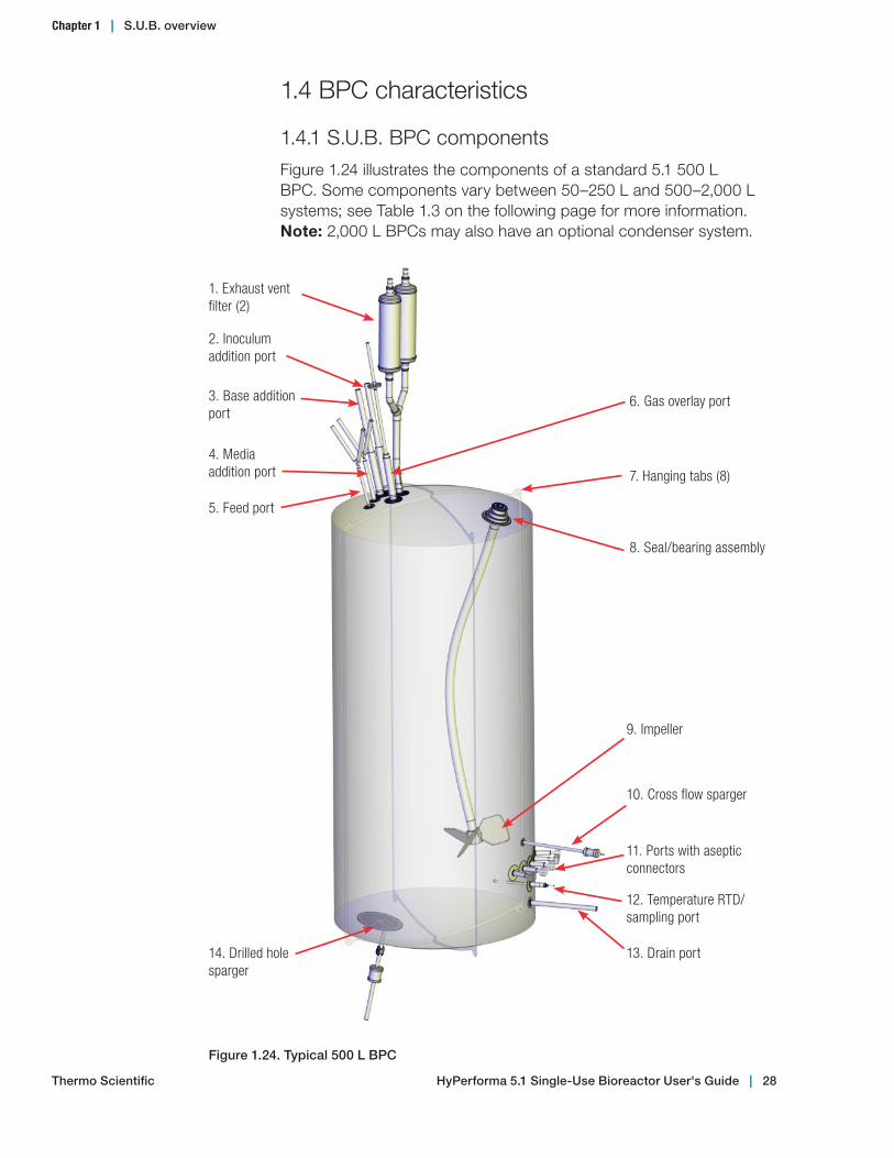
1. Exhaust vent filter (2)
2. Inoculum addition port
3. Base addition port
4. Media addition port
5. Feed port
6. Gas overlay port
7. Hanging tabs (8)
8. Seal/bearing assembly
9. Impeller
10. Cross flow sparger
11. Ports with aseptic connectors
12. Temperature RTD/sampling port
13. Drain port14. Drilled hole sparger
Figure 1.24. Typical 500 L BPC
1.4 BPC characteristics
1.4.1 S.U.B. BPC components
Figure 1.24 illustrates the components of a standard 5.1 500 L BPC. Some components vary between 50–250 L and 500–2,000 L systems; see Table 1.3 on the following page for more information. Note: 2,000 L BPCs may also have an optional condenser system.
Chapter 1 | S.U.B. overview
Thermo Scientific HyPerforma 5.1 Single‑Use Bioreactor User's Guide | 28

Table 1.3. BPC information for Figure 1.24.
Component Description
1. Exhaust vent filterSingle-use capsule filter for exhaust gas exchange; 50 L, 100 L, and 250 L units have one filter, and 500 L, 1,000 L, and 2,000 L units have two filters
2. Inoculum addition port For inoculum addition
3. Base addition port For base addition
4. Media addition port For addition of media
5. Feed port For addition of other liquids
6. Gas overlay port For the introduction of air or other gases; protected by gas filter
7. Hanging tabs (8) For securing BPC inside the S.U.B.
8. Seal/bearing assembly Links with the mixer motor and allows the impeller to turn while retaining integrity of the S.U.B. BPC
9. Impeller Injection molded plastic; Links to seal/bearing assembly by C-Flex tubing
10. Cross flow sparger Supplies oxygen during low-volume mixing
11. Ports with aseptic connectors
For integration of standard 12 mm (0.47 in.) monitoring pH and DO probes
12. Temperature RTD/sampling port
For integration of the temperature probe while retaining integrity of the S.U.B. BPC/needleless sampling or connection to the sampling manifold
13. Drain port Used when draining the S.U.B.
14. Drilled hole sparger* For the introduction of air, oxygen or other gases; integrated into the chamber and protected by gas filters
*Note: 2,000 L BPCs have two drilled hole spargers
Chapter 1 | S.U.B. overview
Thermo Scientific HyPerforma 5.1 Single‑Use Bioreactor User's Guide | 29

1.4.2 S.U.B. BPC features
The cell culture itself is contained inside the BPC, which is supplied gamma irradiated. The chamber is manufactured from film, which is a co-extruded structure specifically designed for biopharmaceutical process usage. All materials are qualified for a broad range of physical, mechanical, biological, and chemical compatibility requirements. Refer to data in our BPC catalog and film validation guides; contact your sales representative for a copy.
SpargersThe standard 5.1 BPC is designed with special spargers (drilled hole, cross flow, and overlay) that produce very efficient mass transfer of oxygen. They typically require much less gas inflow than conventional spargers. Gas flow rates supplied as overlay or through the cross flow sparger should also be reduced as much as possible; this will minimize both liquid evaporation and demand on the exhaust filter. Minimizing gas flow through the drilled hole sparger reduces the occurrence of foam in the headspace that may plug the exhaust filter. For more information, refer to section 3.1.3—Operating Pressure, and section 3.5—Cell Culture Operating Instructions, in this user’s guide.
Exhaust vent filterThe exhaust vent filter used on 50–1,000 L S.U.B.s is a Pall™ KA3 series filter utilizing hydrophobic PVDF membranes. To maintain a sterile connection, the standard BPC is supplied with the filter arrow pointing toward the BPC. This ensures that the filter vents are outside of the sterile connection. For users with more demanding applications, an optional vent filter heater can be used.
The exhaust vent filters used on 2,000 L S.U.B.s are Meissner™ UltraCap™ series filters utilizing hydrophobic PVDF membranes. These filters are provided in normal orientation with the flow arrow on the filter housing pointing away from the BPC. The normal orientation provides maximum filter capacity. No side vents are provided. Condensate must be managed by use of the condenser system or vent filter heater.
ConnectionsMultiple aseptic connection options exist for S.U.B. users. Standard BPCs include tubing welder sections, quick-connects, and CPC™ AseptiQuik™ connections. The BPC is designed with various lengths and dimensions of thermoplastic tubing for the purpose of adding to and dispensing from the BPC.
Chapter 1 | S.U.B. overview
Thermo Scientific HyPerforma 5.1 Single‑Use Bioreactor User's Guide | 30
Sampling portThe S.U.B. is equipped with a small volume sample port that is adjacent to the BPC thermowell. This small-diameter silicone dip tube of 152.4 mm length (6 in.) allows low void volume samples to be taken for cell viability and density, as well as analyte analysis. This dip tube is supplied with a luer lock connector (SmartSite™) that allows for direct sampling or attachment of various sampling manifolds by use of standard luer lock connection. Alternatively, manifolds can be welded onto the C-Flex sample line using a tubing welder.
Thermo Scientific
Chapter 1 | S.U.B. overview
HyPerforma 5.1 Single‑Use Bioreactor User's Guide | 31

Hardware assembly and setup
Chapter contents2.1 Initial installation preparation2.2 Installation and setup
2
Thermo Scientific HyPerforma 5.1 Single‑Use Bioreactor User's Guide | 32
2.1 Initial installation preparation
2.1.1 Hardware shipment and setup
The Single-Use Bioreactor (S.U.B.) hardware will arrive crated. For unpacking instructions and detailed contents of the crate, please refer to the Thermo Scientific HyPerforma 5.1 S.U.B. Packing and Unpacking Guide (DOC0033), and the packaging drawings, which are included in the shipping crate. Be sure to follow the unpacking instructions provided and retain all packaging materials.
2.1.2 Hardware uncrating
The S.U.B. hardware will arrive with the following items:• Outer support container (platform, tank, and control panel)• Drive shaft, resistance temperature detector (RTD), four probe
brackets, and standard tool set (spanner wrench and torque wrench)
• Equipment Turnover Package (ETP), provided on a USB drive (shipped separately)
Detailed instructions for crating, uncrating, and assembly of 50 L, 100 L, 250 L, 500 L, 1,000 L, and 2,000 L S.U.B. units are included in the Thermo Scientific HyPerforma 5.1 S.U.B. Packing and Unpacking Guide (DOC0033). After uncrating, contact your sales representative immediately if any damage has occurred.
2.1.3 Site preparation
Electrical connections for units with AC motors and an electrical control panelS.U.B. hardware using AC motors cannot be used on circuits equipped with ground fault circuit interrupter (GFCI) circuit protection because of the potential for nuisance tripping. The electrical plug on the S.U.B. is a connector that offers a secure ground. These connectors meet the electrical safety codes for portable equipment and are International Electrical Code (IEC) rated (meet IEC standard 60309). This plug provides electrical ground prior to power connection. The supplied electrical receptacle should be hardwired into the facility by a qualified electrical technician; for U.S. installations, the receptacle will require the use of an adapter mounting plate (supplied), which will fit into a two-gang box. For additional information on the adapter mounting plate, please see the ETP. Alternatively, the system can be hardwired directly into the facility. Note: The yellow plug and receptacle are for 120 VAC, and the blue are for 240 VAC S.U.B.s.
Chapter 2 | Hardware assembly and setup
Thermo Scientific HyPerforma 5.1 Single‑Use Bioreactor User's Guide | 33
Electrical connections for 50 L, 100 L, 250 L, and 500 L systems with DC motorsS.U.B. units using DC motors are not supplied with electrical control panels (E-Boxes). When using a DC motor, electrical connections must be supplied by a third-party integrator.
Outer support container preparationEach outer support container is shipped directly from the manufacturer, and arrives with various safety mechanisms in place. Follow the guidelines below to set up the S.U.B. upon arrival.
WARNING: Any procedure that requires the E-Box to be opened should be performed with the main electrical disconnect in the locked out position and all power sources removed from the E-Box. For operator safety, secure the location of the S.U.B. outer support container by disabling the swivel casters before servicing.
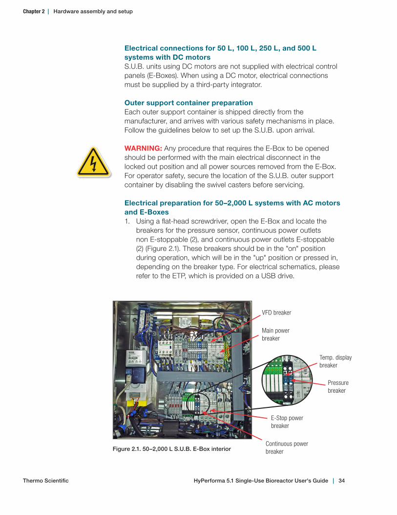
Electrical preparation for 50–2,000 L systems with AC motors and E-Boxes1. Using a flat-head screwdriver, open the E-Box and locate the
breakers for the pressure sensor, continuous power outlets non E-stoppable (2), and continuous power outlets E-stoppable (2) (Figure 2.1). These breakers should be in the "on" position during operation, which will be in the "up" position or pressed in, depending on the breaker type. For electrical schematics, please refer to the ETP, which is provided on a USB drive.
VFD breaker
Continuous power breaker
Temp. display breaker
Figure 2.1. 50–2,000 L S.U.B. E‑Box interior
Main power breaker
E-Stop power breaker
Pressure breaker
Chapter 2 | Hardware assembly and setup
Thermo Scientific HyPerforma 5.1 Single‑Use Bioreactor User's Guide | 34

2. Close the E-Box and lock the panel using a flat-head screwdriver before continuing.
2.2 Installation and setup
2.2.1 Preparing load cells
All manual movements of mobile S.U.B. hardware should be over smooth surfaces, with the S.U.B. empty and disconnected from all power and gas/feed sources. All load cells must be fully locked down in order to move the S.U.B.
Follow the steps below to prepare load cells for use. Figure 2.2 illustrates the location and components of load cells, which will be referenced throughout the load cell preparation process.
A
Lockout nut
38.1 mm (1.5 in.)Tri-clamp
Lockout post
Delrin slip ring
Figure 2.2. Close up view of load cells
1. For S.U.B. hardware units purchased with factory-installed load cells, the load cells are shipped in the locked position (threaded up) for equipment protection.
Chapter 2 | Hardware assembly and setup
Thermo Scientific HyPerforma 5.1 Single‑Use Bioreactor User's Guide | 35
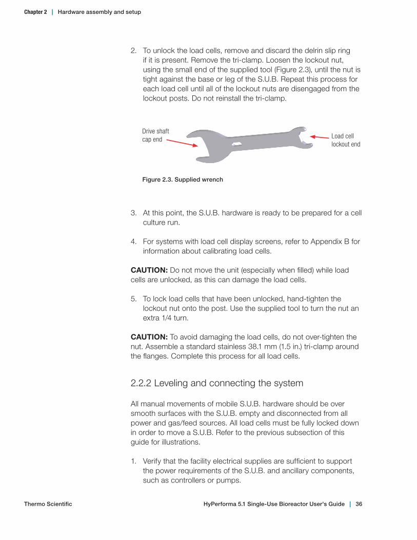
2. To unlock the load cells, remove and discard the delrin slip ring if it is present. Remove the tri-clamp. Loosen the lockout nut, using the small end of the supplied tool (Figure 2.3), until the nut is tight against the base or leg of the S.U.B. Repeat this process for each load cell until all of the lockout nuts are disengaged from the lockout posts. Do not reinstall the tri-clamp.
Drive shaft cap end Load cell
lockout end
Figure 2.3. Supplied wrench
3. At this point, the S.U.B. hardware is ready to be prepared for a cell culture run.
4. For systems with load cell display screens, refer to Appendix B for information about calibrating load cells.
CAUTION: Do not move the unit (especially when filled) while load cells are unlocked, as this can damage the load cells.
5. To lock load cells that have been unlocked, hand-tighten the lockout nut onto the post. Use the supplied tool to turn the nut an extra 1/4 turn.
CAUTION: To avoid damaging the load cells, do not over-tighten the nut. Assemble a standard stainless 38.1 mm (1.5 in.) tri-clamp around the flanges. Complete this process for all load cells.
2.2.2 Leveling and connecting the system
All manual movements of mobile S.U.B. hardware should be over smooth surfaces with the S.U.B. empty and disconnected from all power and gas/feed sources. All load cells must be fully locked down in order to move a S.U.B. Refer to the previous subsection of this guide for illustrations.
1. Verify that the facility electrical supplies are sufficient to support the power requirements of the S.U.B. and ancillary components, such as controllers or pumps.
Chapter 2 | Hardware assembly and setup
Thermo Scientific HyPerforma 5.1 Single‑Use Bioreactor User's Guide | 36
2. Locate the outer support container in the area for the cell culture run.
3. When monitoring the batch volume, the unit may be placed on a weight scale if load cells are not part of the system. Other methods may be used to measure all incoming and outgoing liquids.
4. Level the platform by disabling the swivel casters on the bottom of the outer support container. This is accomplished by threading the leveling feet (at the center of each caster) to the floor.
5. Verify the location of the pH/DO controllers and assure that the cable and tubing lengths are sufficient.
WARNING: Risk of electrical shock.
6. Verify that the main power is off and the emergency stop is pulled out. Note: The emergency stop disconnects all power to the system. An alarm buzzer will sound when the emergency stop is activated.
7. Verify that the main motor power switch is in the "off" position.
8. Connect all electrical plugs to facility power. Note: 120 VAC 250 L S.U.B.s should be connected to a dedicated 20 A circuit. Refer to hardware/electrical labels and schematics to ensure proper electrical voltage is connected to the S.U.B. The main power switch can now be turned on.
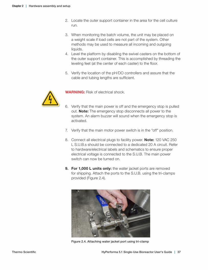
9. For 1,000 L units only: the water jacket ports are removed for shipping. Attach the ports to the S.U.B. using the tri-clamps provided (Figure 2.4).
Figure 2.4. Attaching water jacket port using tri‑clamp
Chapter 2 | Hardware assembly and setup
Thermo Scientific HyPerforma 5.1 Single‑Use Bioreactor User's Guide | 37

10. Connect water inlet and outlet lines from the temperature control unit quick-connects to the jacket (Figure 2.5). For 50 L, 100 L, 250 L, 500 L, and 2,000 L units, the inlet is typically on the left side if you are facing the connectors. For the 1,000 L S.U.B. unit, the inlet is the lower connection, and the outlet is the upper.
11. Insert the sparge line support (Figure 2.6) into the bottom of the S.U.B. unit, directly below where the sparger will be placed. This piece holds the sparge line vertically for maximum effectiveness. The sparge line can be wound through the coil of the holder to keep the sparger oriented properly.
Inlet port
Outlet port
Figure 2.5. Inlet and outlet ports
Figure 2.6. Sparge line support
Chapter 2 | Hardware assembly and setup
Thermo Scientific HyPerforma 5.1 Single‑Use Bioreactor User's Guide | 38
2.2.3 Verifying drive shaft segments for 2,000 L systems
The 2,000 L S.U.B. is supplied with a special drive shaft that differs in appearance and material when compared to the metallic shafts used in smaller S.U.B. sizes. Due to the higher mechanical stress generated in 2,000 L S.U.B.s, these systems require drive shafts made of carbon fiber composites to reduce the weight of the long shaft.
Note: Always maintain a log history of the drive shaft and confirm that it has sufficient life remaining. For warranty purposes, users must show documentation of proper drive shaft use. A sample log for documenting drive shaft use is provided in Appendix D of this publication. If the age or history of a drive shaft is questionable, it should be discarded.
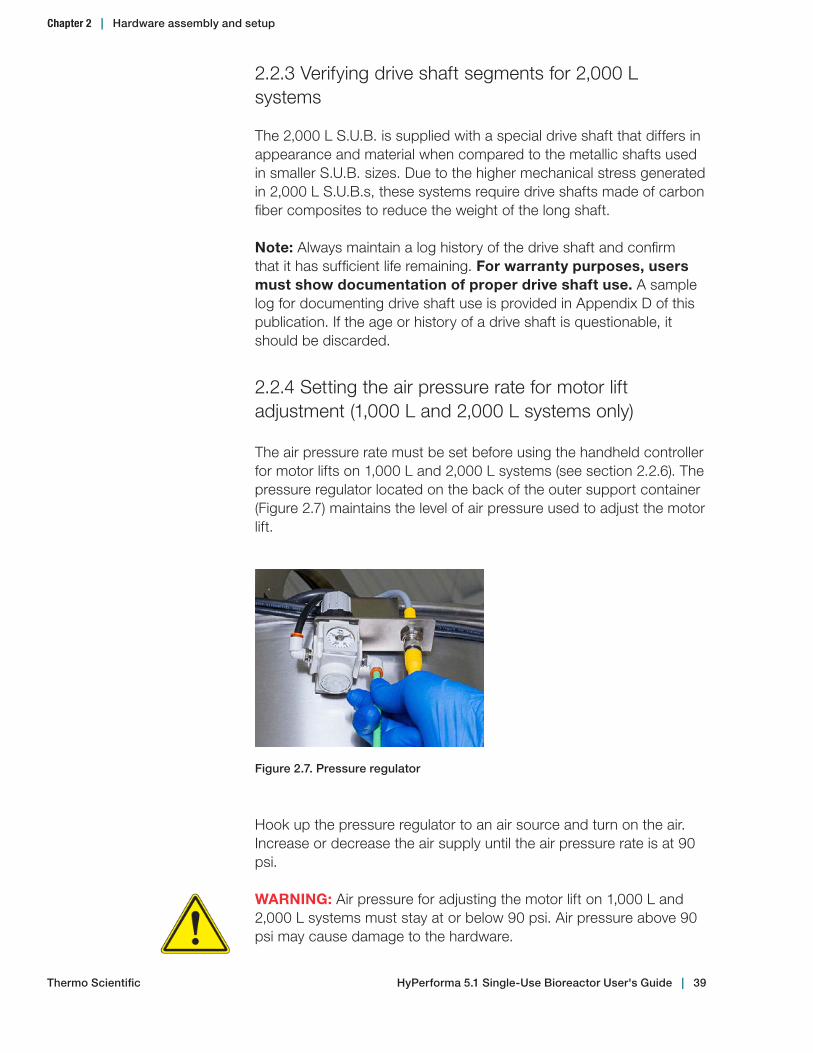
2.2.4 Setting the air pressure rate for motor lift adjustment (1,000 L and 2,000 L systems only)
The air pressure rate must be set before using the handheld controller for motor lifts on 1,000 L and 2,000 L systems (see section 2.2.6). The pressure regulator located on the back of the outer support container (Figure 2.7) maintains the level of air pressure used to adjust the motor lift.
Hook up the pressure regulator to an air source and turn on the air. Increase or decrease the air supply until the air pressure rate is at 90 psi.
WARNING: Air pressure for adjusting the motor lift on 1,000 L and 2,000 L systems must stay at or below 90 psi. Air pressure above 90 psi may cause damage to the hardware.
Figure 2.7. Pressure regulator
Chapter 2 | Hardware assembly and setup
Thermo Scientific HyPerforma 5.1 Single‑Use Bioreactor User's Guide | 39
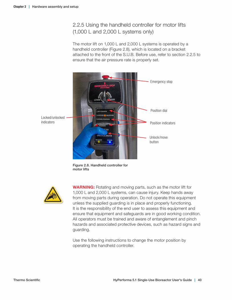
Figure 2.8. Handheld controller for motor lifts
Emergency stop
Position dial
Unlock/move button
Position indicators
Locked/unlocked indicators
2.2.5 Using the handheld controller for motor lifts (1,000 L and 2,000 L systems only)
The motor lift on 1,000 L and 2,000 L systems is operated by a handheld controller (Figure 2.8), which is located on a bracket attached to the front of the S.U.B. Before use, refer to section 2.2.5 to ensure that the air pressure rate is properly set.
WARNING: Rotating and moving parts, such as the motor lift for 1,000 L and 2,000 L systems, can cause injury. Keep hands away from moving parts during operation. Do not operate this equipment unless the supplied guarding is in place and properly functioning. It is the responsibility of the end user to assess this equipment and ensure that equipment and safeguards are in good working condition. All operators must be trained and aware of entanglement and pinch hazards and associated protective devices, such as hazard signs and guarding.
Use the following instructions to change the motor position by operating the handheld controller.
Chapter 2 | Hardware assembly and setup
Thermo Scientific HyPerforma 5.1 Single‑Use Bioreactor User's Guide | 40

2. Hold down the unlock/move button on the handheld controller to unlock the motor. The "unlocked" indicator on the handheld controller will be lit orange (see Figure 2.8). While holding down the unlock/move button, turn the position dial to the left to lower the motor position, or to the right to raise the motor position. Note: The motor must be in either the "up" or "down" position. If the motor is not in either position, the "intermediate position" indicator will be lit red as a warning (see Figure 2.8).
3. After the motor angle is in either the "up" or "down" position, release the unlock/move button to lock the pin located on the side of the motor. The "locked" indicator will be lit green.
Important notes: • Prior to BPC loading, the motor should be in the "up" position.• After the BPC has been loaded and filled with air, the motor
should be moved to the "down" position.• To stop the handheld controller and movement of the motor lift in
the case of an emergency, use the red Emergency Stop (E-Stop) button on the top of the handheld controller.
Figure 2.9. Red status sensor on motor cap
Status sensor on motor cap
1. Before adjusting the motor lift, verify that the motor cap is closed. If the cap is open, the motor will not run. The red status sensor on the motor cap (Figure 2.9) communicates to the handheld controller if the cap is open or closed.
Chapter 2 | Hardware assembly and setup
Thermo Scientific HyPerforma 5.1 Single‑Use Bioreactor User's Guide | 41
Operating information
Chapter contents3.1 General system operating information 3.2 BPC and drive shaft loading instructions for 50 L, 100 L, and 250 L systems3.3 BPC and drive shaft loading instructions for 500 L and 1,000 L systems3.4 BPC and drive shaft loading, and condenser system setup instructions for 2,000 L systems3.5 Probe preparation and insertion3.6 Cell culture operating instructions3.7 Verification procedures
3
Thermo Scientific HyPerforma 5.1 Single‑Use Bioreactor User's Guide | 42

3.1 General system operating information
3.1.1 BPC preparation
Each outer support container is designed for a specific BPC. Confirm that the correct volume and type of BPC is being used for the corresponding volume outer support container. 50–500 L 5.1 BPCs are different than 2.1 BPCs, and are labeled for 5:1 mixing. Sections 3.2, 3.3, and 3.4 cover the installation and setup of BPCs. Follow these instructions in the order in which they are presented.
3.1.2 BPC handling instructions
If you are using a sharp object when opening outer polybags, take care to avoid damaging the BPC. Do not drag containers over corners or sharp objects. Do not lift the container by the corners or top seams. Carefully coil the tubing on top of the BPC to prevent puncturing the container with cable ties or clamps. Use cushioning between the tubing and the container in storage and transport.
3.1.3 BPC operating information
Working volumeEach S.U.B. is designed for a specific working volume range. The minimum working volume and the rated working volume are listed in the specification tables provided in Chapter 4 of this user's guide. The total volume listed includes the headspace needed for proper aeration and gas management.
Note: Actual working volumes should not exceed the indicated rated working volumes by more than 10%. In addition, working volumes less than 20% of the rated volume can result in damage to the BPC and/or the S.U.B. hardware.
Operating pressureThe BPC does not operate as a closed system; it has both inlet and exhaust filters that are utilized to maintain a sterile environment for cell growth. However, conditions can be encountered when the gas inlet flow rate may exceed the exhaust flow rate. This may be encountered in the unlikely event of a pressure regulator failure on a gas feed, or when excessive foam within the bioreactor creates a vent blockage.
Chapter 3 | Operating information
Thermo Scientific HyPerforma 5.1 Single‑Use Bioreactor User's Guide | 43

WARNING: The BPC is not rated as a pressure vessel. Gas pressure within the BPC headspace should not exceed 0.03 bar (0.5 psi) at any time. Pressure above 0.03 bar (0.5 psi) may result in BPC damage or personal injury.
• More demanding applications may warrant an optional exhaust vent heater.
• If foaming is excessive in your cell culture process, it is best to reduce the operating volume of the process to 80% of maximum rated working volume of the S.U.B. system being used to provide greater headspace volume.
• Single-use pressure transducers are available on custom S.U.B. configurations. This technology combined with high-level control systems (common with industrial applications) can regulate gas pressure within the confines of the S.U.B.
AerationGas to liquid mass transfer in cell culture bioreactors is controlled by the solubility of the gas in the liquid, its distribution, and the temperature and pressure. Direct air sparging provides for the oxygen requirements of eukaryotic cell cultures. It allows optimal aeration of the culture process and effective carbon dioxide stripping. However, when compared to 2:1 mixing (50% working volume), 5:1 mixing causes more carbon dioxide buildup in the extra headspace in the BPC when operating at 20% working volume. This blanket of carbon dioxide may prevent proper cell respiration.
A cross flow sparging strategy disrupts the dense carbon dioxide blanket at the bottom of the BPC headspace, which lets users take advantage of low-volume mixing without compromising cell cultures. This strategy requires temporarily rerouting the overlay sparger to a cross flow port near the surface of the liquid when operating at 20% working volume. When the volume is increased above 20%, the sparge line should be returned to the standard overlay port to reduce carbon dioxide in the headspace, and a single drilled hole sparger is the main source of aeration.
For more information about possible sparging strategies, review the test data in the Thermo Scientific HyPerforma 5.1 S.U.B. Validation Guide (DOC0023).
Chapter 3 | Operating information
Thermo Scientific HyPerforma 5.1 Single‑Use Bioreactor User's Guide | 44

Aseptic connectionsThe most commonly recommended process for making connections to the tubing lines is with an aseptic tubing fuser. Other connection options are available as a custom BPC assembly. By following the recommended tubing welder operating instructions, successful connections can be made for filling, supplementing, sampling, or dispensing from the BPC as needed.
Draining and harvestThe S.U.B. is equipped with a bottom drain line that allows for liquid harvest by means of peristaltic pump. Connection of the bottom drain line can be accomplished by use of a tubing welder or the fitting that is provided. The bottom drain exits the BPC at the lowest vertical position on the side of the S.U.B. This allows for easy access for the user and minimizes the accumulation of cells in the area of the drain during the cell culture run. Manipulation of the BPC as the last few liters of media drain will minimize liquid hold-up within the S.U.B. The 2,000 L S.U.B. is provided with a 25.4 mm (1 in.) bottom drain near the center line of the tank bottom.
3.1.4 Hardware operating information
Heating performanceHeating times for 5.1 S.U.B. systems vary based on liquid volume and temperature, ambient or heating liquid temperature, sparging rate, and mixing rate. For heating times, see Table 3.1.
WARNING: Do not heat the system if the BPC is not at 20% liquid volume or greater. Batch temperature should not exceed 40°C.
Table 3.1. Heating times for S.U.B. systems. Ambient temperature of 25°C –values assume a TCU heater size of at least 9 W per batch liter.
System Liquid batch volume (20% / 100%) Initial liquid Liquid
targetTime
(20% / 100%)
50 L 10 L/50 L 5°C 37°C 1 hr/1.1 hr
100 L 20 L/100 L 5°C 37°C 0.9 hr/1.6 hr
250 L 50 L/250 L 5°C 37°C 1.1 hr/3.4 hr
500 L 100 L/500 L 5°C 37°C 1.1 hr/2.2 hr
1,000 L 200 L/1,000 L 5°C 37°C 1.2 hr/4.1 hr
2,000 L 400 L/2,000 L 5°C 37°C 1.4 hr/4.0 hr
Note: Conditions may vary based on your system connections and environment.
Chapter 3 | Operating information
Thermo Scientific HyPerforma 5.1 Single‑Use Bioreactor User's Guide | 45

Protective earth grounding (units with AC motors)For units with AC motors, protective earth grounding for the S.U.B. hardware system and the controller is provided through the ground terminal of the power plug. Source power to the controller must provide protective earth grounding to this terminal in order to minimize the hazard of a possible shock in the occurrence of a fault condition. Please refer to Appendix A for information about electrical receptacles. A ground wire is provided underneath the S.U.B. and must be tied to the controller before operation.
Agitation control interface for units with AC motors and E-Box enclosuresThe agitation control interface utilizes a digital display to indicate stirring speed in units of revolutions per minute (rpm). Power is supplied to the motor by a two-position power switch that is illuminated in green when turned to the "on" position (right position). The agitation should not be operated at volumes less than 20%. Stirring speed is adjusted using the up and down arrows on the agitation keypad interface on the E-Box, or using the settings on an integrated third-party controller. Due to the auto-restart capabilities of the S.U.B., the green start button on the keypad has been disabled; however, the red stop button on the keypad is active.
If the red stop button has been used to stop the motor, the controller can be reset and agitation restarted by using the main motor toggle switch on the left side of the E-Box. For more information, see the illustrations in the E-Box detail in section 4.3.
Circuit protection (units with AC motors)Electrical components of the S.U.B. are equipped with circuit protection. The variable frequency drive used to power the mixer motor is protected by the use of a 10 A double pull resettable breaker with a type C time delay (5-10 x LN). Other components, such as the temperature controller and heating element, are protected with resettable breakers.
In the case of an electrical fault condition, these safety devices are designed to protect the user from electrical shock and prevent electrical system components from being damaged. Fuses can be replaced and/or the breakers reset once the fault condition is resolved.
Chapter 3 | Operating information
Thermo Scientific HyPerforma 5.1 Single‑Use Bioreactor User's Guide | 46
Electrical breaker notes:• The normal "on" setting for these breakers is in the up position.• A tripped breaker will be in the mid position.• The "off" setting is in the fully down position.• To reset a tripped breaker, it must first be moved from the mid
position to the "off" setting (fully down position) before moving it to the "on" setting (fully up position).
Scales and weighing systemsMonitoring liquid volume within the S.U.B. during operation can be critical in cell culture applications that involve nutrient media feeds. This can also be a useful method for increasing the scalability of the S.U.B. by starting the process run at minimum operating volume. The ability to track operating volume by use of load cells or weigh scales allows the user the ability to control liquid volume and cell density as the bioreactor is increased to rated working volume during the process run.
A load cell kit for weight/volume measurement is available for all S.U.B. units, which can be installed at the factory or can be added later by a certified service technician. The load cell kit comes with three load cells, summing block, wiring, and display with a choice of several interfaces.
Refer to Appendix B for load cell display calibration instructions. Ensure that load cells are locked down before any movement of the S.U.B. unit.
To lock the load cells before transporting any size S.U.B., follow the steps below and refer to Figures 2.2 and 2.3 in section 2.1.3.
1. Hand-tighten the load cell lockout nut onto the load cell lockout post. You may need to use the small end of the supplied wrench to loosen the load cell lockout nut from the bottom of the base.
2. After the nut is hand-tightened against the post, use the small end of the supplied wrench to turn it an extra 1/4 turn.
CAUTION: To avoid damaging the load cell, do not overtighten the nut.
Chapter 3 | Operating information
Thermo Scientific HyPerforma 5.1 Single‑Use Bioreactor User's Guide | 47

3. Assemble a standard stainless 28.6 mm (1.5 in.) tri-clamp around the flanges.
4. Repeat steps 1 through 3 for all load cells on the S.U.B.
3.1.5 External data logging and control
Digital display weighing scales can be sourced from manufacturers such as Mettler Toledo. Bench top scales are commonly used to measure the amount of bulk source media stored in a smaller-volume BPC as it is transferred by peristaltic pump into the S.U.B. Floor scales can be used to measure the fluid content within the S.U.B. This is accomplished by rolling the S.U.B. onto the scale platform and leveling the S.U.B. skid once in position.
The S.U.B. hardware systems are designed to allow advanced users to control all aspects of the operation of the bioreactor. Contact technical support for Thermo Scientific HyPerforma products general integration guidance.
Chapter 3 | Operating information
Thermo Scientific HyPerforma 5.1 Single‑Use Bioreactor User's Guide | 48
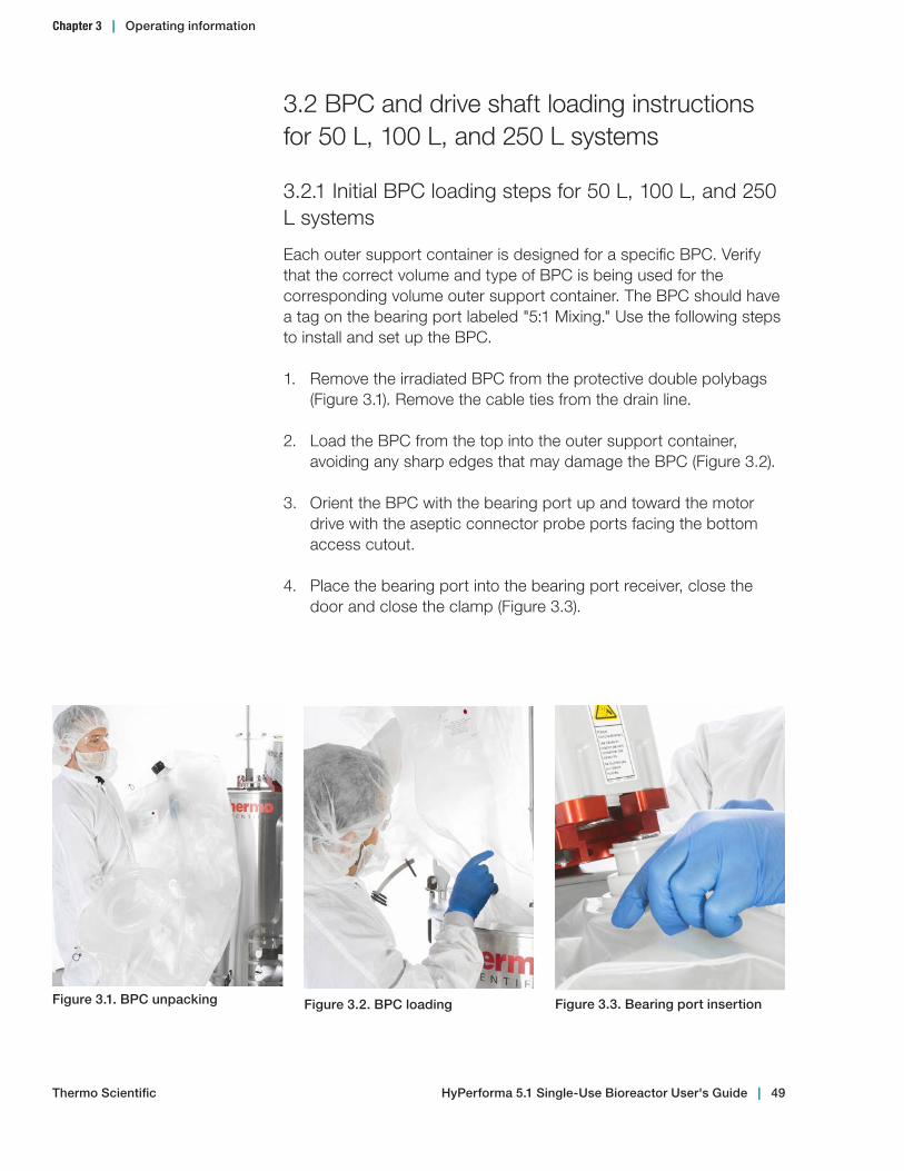
3.2 BPC and drive shaft loading instructions for 50 L, 100 L, and 250 L systems
3.2.1 Initial BPC loading steps for 50 L, 100 L, and 250 L systems
Each outer support container is designed for a specific BPC. Verify that the correct volume and type of BPC is being used for the corresponding volume outer support container. The BPC should have a tag on the bearing port labeled "5:1 Mixing." Use the following steps to install and set up the BPC.
1. Remove the irradiated BPC from the protective double polybags (Figure 3.1). Remove the cable ties from the drain line.
2. Load the BPC from the top into the outer support container, avoiding any sharp edges that may damage the BPC (Figure 3.2).
3. Orient the BPC with the bearing port up and toward the motor drive with the aseptic connector probe ports facing the bottom access cutout.
4. Place the bearing port into the bearing port receiver, close the door and close the clamp (Figure 3.3).
Figure 3.1. BPC unpacking Figure 3.2. BPC loading Figure 3.3. Bearing port insertion
Chapter 3 | Operating information
Thermo Scientific HyPerforma 5.1 Single‑Use Bioreactor User's Guide | 49
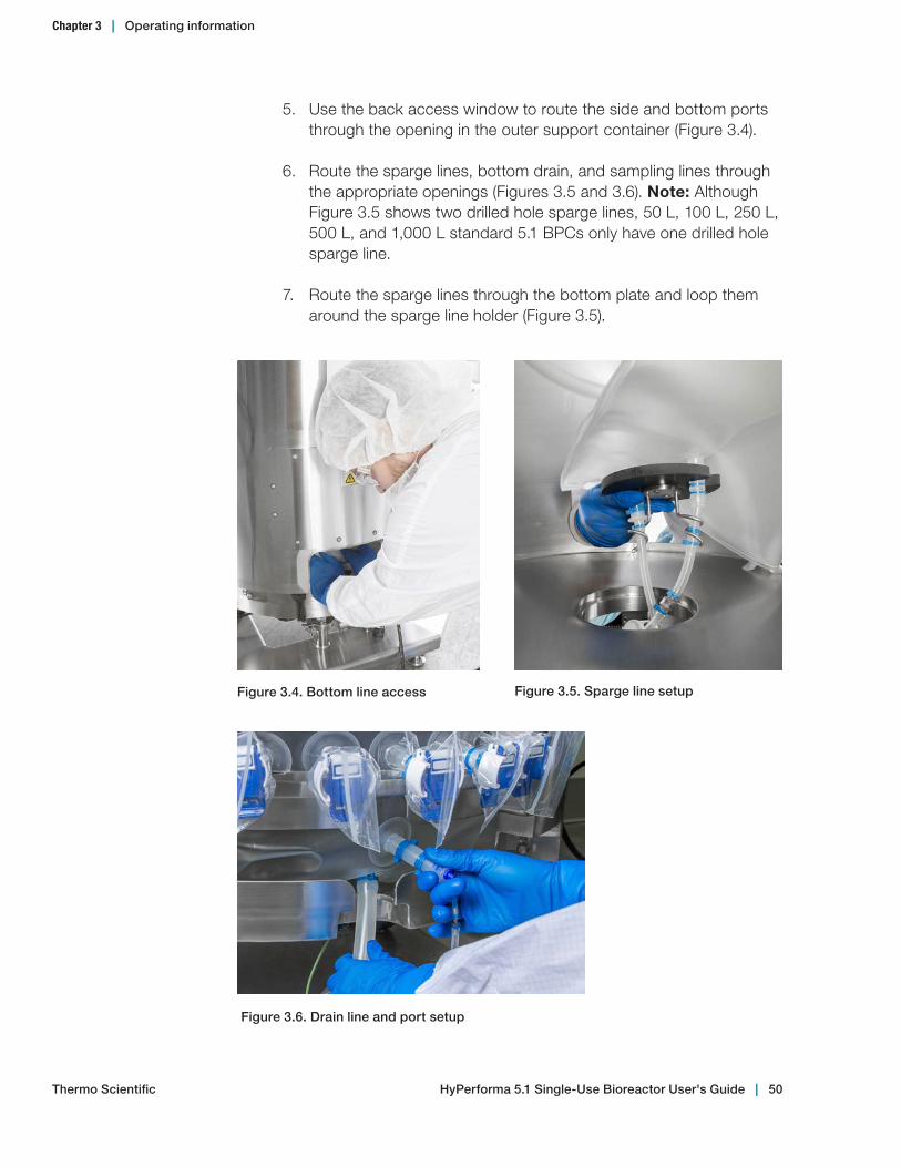
5. Use the back access window to route the side and bottom ports through the opening in the outer support container (Figure 3.4).
6. Route the sparge lines, bottom drain, and sampling lines through the appropriate openings (Figures 3.5 and 3.6). Note: Although Figure 3.5 shows two drilled hole sparge lines, 50 L, 100 L, 250 L, 500 L, and 1,000 L standard 5.1 BPCs only have one drilled hole sparge line.
7. Route the sparge lines through the bottom plate and loop them around the sparge line holder (Figure 3.5).
Figure 3.4. Bottom line access Figure 3.5. Sparge line setup
Figure 3.6. Drain line and port setup
Chapter 3 | Operating information
Thermo Scientific HyPerforma 5.1 Single‑Use Bioreactor User's Guide | 50
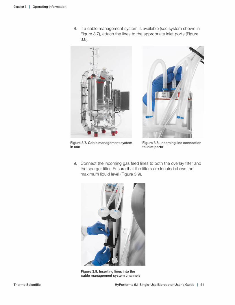
8. If a cable management system is available (see system shown in Figure 3.7), attach the lines to the appropriate inlet ports (Figure 3.8).
Figure 3.7. Cable management system in use
Figure 3.9. Inserting lines into the cable management system channels
Figure 3.8. Incoming line connection to inlet ports
9. Connect the incoming gas feed lines to both the overlay filter and the sparger filter. Ensure that the filters are located above the maximum liquid level (Figure 3.9).
Chapter 3 | Operating information
Thermo Scientific HyPerforma 5.1 Single‑Use Bioreactor User's Guide | 51
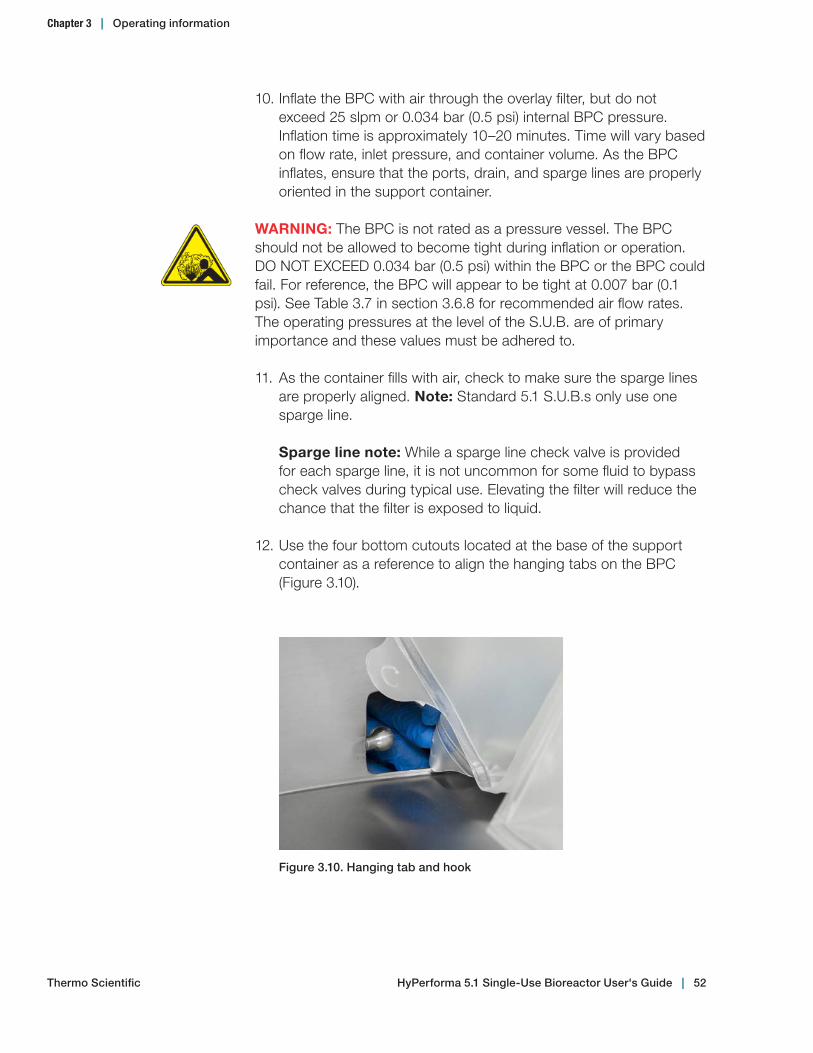
10. Inflate the BPC with air through the overlay filter, but do not exceed 25 slpm or 0.034 bar (0.5 psi) internal BPC pressure. Inflation time is approximately 10–20 minutes. Time will vary based on flow rate, inlet pressure, and container volume. As the BPC inflates, ensure that the ports, drain, and sparge lines are properly oriented in the support container.
WARNING: The BPC is not rated as a pressure vessel. The BPC should not be allowed to become tight during inflation or operation. DO NOT EXCEED 0.034 bar (0.5 psi) within the BPC or the BPC could fail. For reference, the BPC will appear to be tight at 0.007 bar (0.1 psi). See Table 3.7 in section 3.6.8 for recommended air flow rates. The operating pressures at the level of the S.U.B. are of primary importance and these values must be adhered to.
11. As the container fills with air, check to make sure the sparge lines are properly aligned. Note: Standard 5.1 S.U.B.s only use one sparge line.
Sparge line note: While a sparge line check valve is provided for each sparge line, it is not uncommon for some fluid to bypass check valves during typical use. Elevating the filter will reduce the chance that the filter is exposed to liquid.
12. Use the four bottom cutouts located at the base of the support container as a reference to align the hanging tabs on the BPC (Figure 3.10).
Figure 3.10. Hanging tab and hook
HyPerforma 5.1 Single‑Use Bioreactor User's Guide | 52
Chapter 3 | Operating information
Thermo Scientific
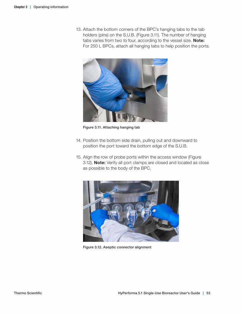
13. Attach the bottom corners of the BPC’s hanging tabs to the tab holders (pins) on the S.U.B. (Figure 3.11). The number of hanging tabs varies from two to four, according to the vessel size. Note: For 250 L BPCs, attach all hanging tabs to help position the ports.
Figure 3.11. Attaching hanging tab
14. Position the bottom side drain, pulling out and downward to position the port toward the bottom edge of the S.U.B.
15. Align the row of probe ports within the access window (Figure 3.12). Note: Verify all port clamps are closed and located as close as possible to the body of the BPC.
Figure 3.12. Aseptic connector alignment
HyPerforma 5.1 Single‑Use Bioreactor User's Guide | 53
Chapter 3 | Operating information
Thermo Scientific

16. Connect the media ground clip to the stainless steel insert in the sample line on the BPC. This step grounds the media inside the BPC and helps to eliminate electrostatic charge (Figure 3.13).
Figure 3.13. Media ground clip connection
Ground clip connection
Chapter 3 | Operating information
Thermo Scientific HyPerforma 5.1 Single‑Use Bioreactor User's Guide | 54

3.2.2 Drive shaft insertion for 50 L, 100 L, and 250 L systems
WARNING: Before you insert the drive shaft, the BPC must be adequately inflated so that it is sitting upright in the outer support container.
Figure 3.14 illustrates the components of the motor and mixing assembly. The parts labeled on the figure will be referenced throughout the drive shaft insertion process. Use the steps on the following pages to insert the drive shaft.
Motor cap
Drive shaft head
Motor drive keyway
Latch pin
Motor
Hollow pass-through
Safety cover
Drive shaft
Figure 3.14. Motor and mixing assembly
Chapter 3 | Operating information
Thermo Scientific HyPerforma 5.1 Single‑Use Bioreactor User's Guide | 55
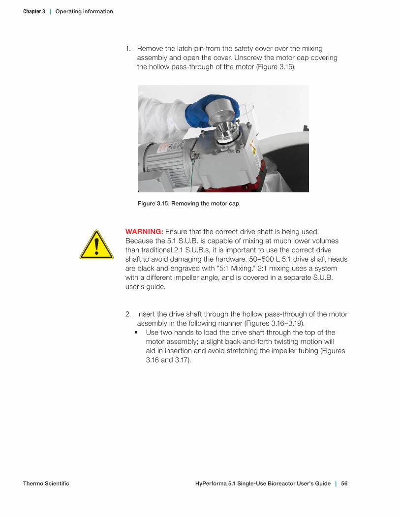
Figure 3.15. Removing the motor cap
1. Remove the latch pin from the safety cover over the mixing assembly and open the cover. Unscrew the motor cap covering the hollow pass-through of the motor (Figure 3.15).
WARNING: Ensure that the correct drive shaft is being used. Because the 5.1 S.U.B. is capable of mixing at much lower volumes than traditional 2.1 S.U.B.s, it is important to use the correct drive shaft to avoid damaging the hardware. 50–500 L 5.1 drive shaft heads are black and engraved with "5:1 Mixing." 2:1 mixing uses a system with a different impeller angle, and is covered in a separate S.U.B. user's guide.
2. Insert the drive shaft through the hollow pass-through of the motor assembly in the following manner (Figures 3.16–3.19).
• Use two hands to load the drive shaft through the top of the motor assembly; a slight back-and-forth twisting motion will aid in insertion and avoid stretching the impeller tubing (Figures 3.16 and 3.17).
Chapter 3 | Operating information
Thermo Scientific HyPerforma 5.1 Single‑Use Bioreactor User's Guide | 56
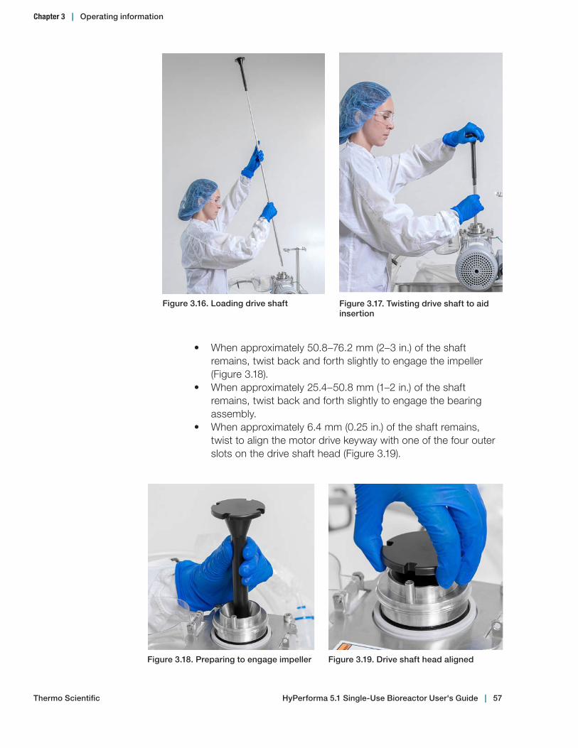
• When approximately 50.8–76.2 mm (2–3 in.) of the shaft remains, twist back and forth slightly to engage the impeller (Figure 3.18).
• When approximately 25.4–50.8 mm (1–2 in.) of the shaft remains, twist back and forth slightly to engage the bearing assembly.
• When approximately 6.4 mm (0.25 in.) of the shaft remains, twist to align the motor drive keyway with one of the four outer slots on the drive shaft head (Figure 3.19).
Figure 3.16. Loading drive shaft Figure 3.17. Twisting drive shaft to aid insertion
Figure 3.18. Preparing to engage impeller Figure 3.19. Drive shaft head aligned
Chapter 3 | Operating information
Thermo Scientific HyPerforma 5.1 Single‑Use Bioreactor User's Guide | 57
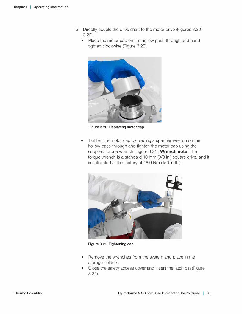
3. Directly couple the drive shaft to the motor drive (Figures 3.20–3.22).
• Place the motor cap on the hollow pass-through and hand-tighten clockwise (Figure 3.20).
Figure 3.20. Replacing motor cap
• Tighten the motor cap by placing a spanner wrench on the hollow pass-through and tighten the motor cap using the supplied torque wrench (Figure 3.21). Wrench note: The torque wrench is a standard 10 mm (3/8 in.) square drive, and it is calibrated at the factory at 16.9 Nm (150 in-lb.).
Figure 3.21. Tightening cap
• Remove the wrenches from the system and place in the storage holders.
• Close the safety access cover and insert the latch pin (Figure 3.22).
Chapter 3 | Operating information
Thermo Scientific HyPerforma 5.1 Single‑Use Bioreactor User's Guide | 58

Figure 3.22. Replacing and latching cover
3.2.3 Final installation steps for 50 L, 100 L, and 250 L systems
1. The air supply to the overlay can be turned off once the drive shaft has been inserted.
2. Optional: Wrap and secure the vent filter heater on the exhaust filter. Connect the heater to the controller and verify that it is plugged into an appropriate 120 or 240 VAC outlet, then connect the power cord to the controller. The controller is preset to 50°C.
3. Secure the exhaust vent filter on its holder (Figure 3.23). Note: Some custom BPCs are supplied with dual exhaust vents. The vent bracket can accommodate 10 in. and 4 in. filters in either single or dual configuration.
Figure 3.23. Vent filter installation
Chapter 3 | Operating information
Thermo Scientific HyPerforma 5.1 Single‑Use Bioreactor User's Guide | 59

4. Attach the overlay sparge line and any other lines to the cable management system, if available (Figure 3.24).
Figure 3.24. Optional cable management system on a S.U.B. unit
5. Position and close a bar clamp on the bottom drain line as close as possible to the BPC port (Figure 3.25).
Figure 3.25. Bar clamp installation
6. Remove the plastic insert located in the thermowell, if present.
Chapter 3 | Operating information
Thermo Scientific HyPerforma 5.1 Single‑Use Bioreactor User's Guide | 60
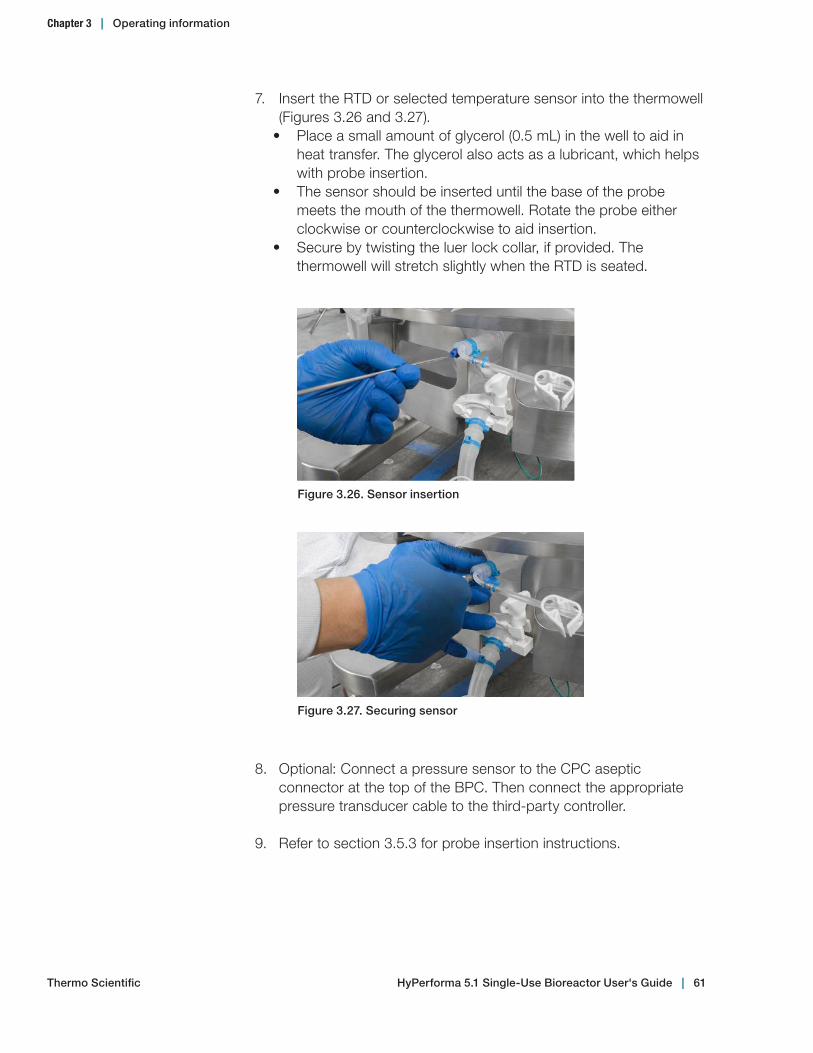
7. Insert the RTD or selected temperature sensor into the thermowell (Figures 3.26 and 3.27).
• Place a small amount of glycerol (0.5 mL) in the well to aid in heat transfer. The glycerol also acts as a lubricant, which helps with probe insertion.
• The sensor should be inserted until the base of the probe meets the mouth of the thermowell. Rotate the probe either clockwise or counterclockwise to aid insertion.
• Secure by twisting the luer lock collar, if provided. The thermowell will stretch slightly when the RTD is seated.
Figure 3.26. Sensor insertion
Figure 3.27. Securing sensor
8. Optional: Connect a pressure sensor to the CPC aseptic connector at the top of the BPC. Then connect the appropriate pressure transducer cable to the third-party controller.
9. Refer to section 3.5.3 for probe insertion instructions.
Chapter 3 | Operating information
Thermo Scientific HyPerforma 5.1 Single‑Use Bioreactor User's Guide | 61
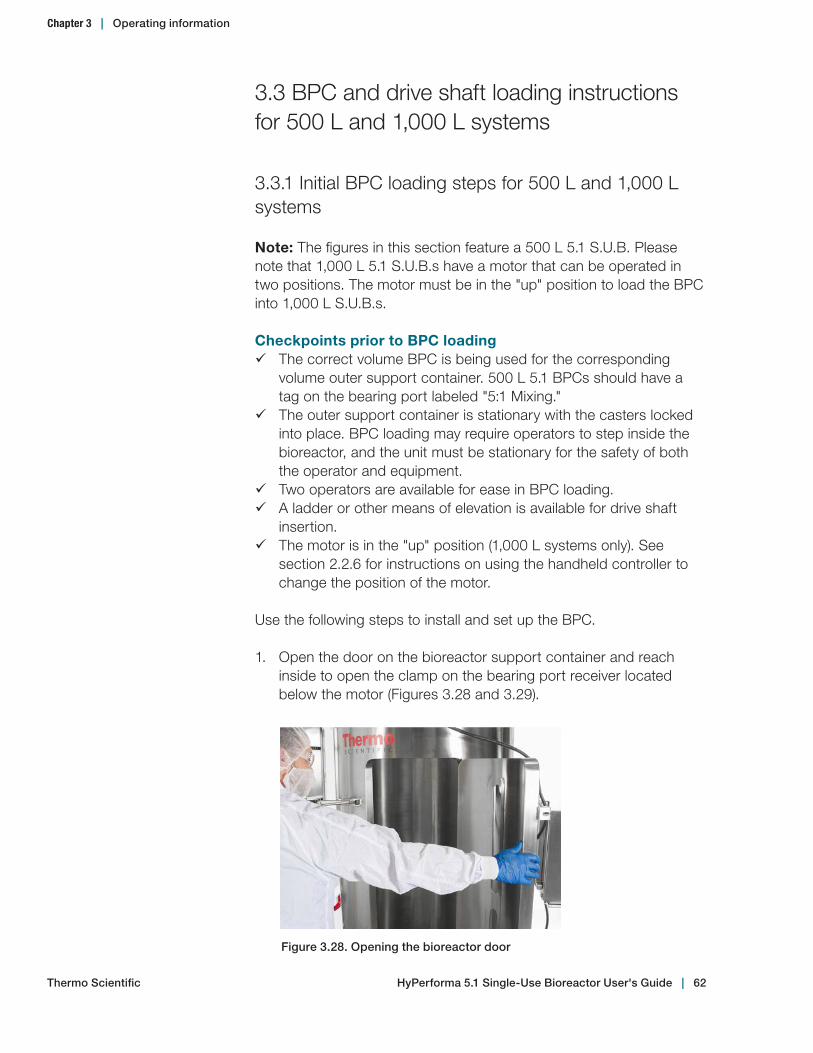
3.3 BPC and drive shaft loading instructions for 500 L and 1,000 L systems
3.3.1 Initial BPC loading steps for 500 L and 1,000 L systems
Note: The figures in this section feature a 500 L 5.1 S.U.B. Please note that 1,000 L 5.1 S.U.B.s have a motor that can be operated in two positions. The motor must be in the "up" position to load the BPC into 1,000 L S.U.B.s.
Checkpoints prior to BPC loading 9 The correct volume BPC is being used for the corresponding
volume outer support container. 500 L 5.1 BPCs should have a tag on the bearing port labeled "5:1 Mixing."
9 The outer support container is stationary with the casters locked into place. BPC loading may require operators to step inside the bioreactor, and the unit must be stationary for the safety of both the operator and equipment.
9 Two operators are available for ease in BPC loading. 9 A ladder or other means of elevation is available for drive shaft
insertion. 9 The motor is in the "up" position (1,000 L systems only). See
section 2.2.6 for instructions on using the handheld controller to change the position of the motor.
Use the following steps to install and set up the BPC.
1. Open the door on the bioreactor support container and reach inside to open the clamp on the bearing port receiver located below the motor (Figures 3.28 and 3.29).
Figure 3.28. Opening the bioreactor door
Chapter 3 | Operating information
Thermo Scientific HyPerforma 5.1 Single‑Use Bioreactor User's Guide | 62

2. Remove the irradiated BPC from the protective double polybags (Figure 3.30). Do not remove the polybags from the line sets at this stage as the BPC may become difficult to manage. Do not allow the BPC or line sets to touch the floor.
3. Reach into or step inside the outer support container with the front face (bearing port side) of the BPC oriented toward the motor (Figure 3.31).
Figure 3.30. BPC in protective polybags Figure 3.31. Bearing port orientation
4. Place the top line sets, still in polybags, over the top edge of the tank (Figure 3.32). This will keep the container from being restricted during the air inflation step.
Figure 3.29. Close‑up of bearing receiver clamp
Chapter 3 | Operating information
Thermo Scientific HyPerforma 5.1 Single‑Use Bioreactor User's Guide | 63
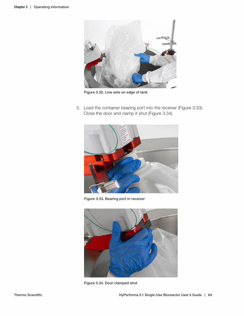
5. Load the container bearing port into the receiver (Figure 3.33). Close the door and clamp it shut (Figure 3.34).
Figure 3.33. Bearing port in receiver
Figure 3.34. Door clamped shut
Figure 3.32. Line sets on edge of tank
Chapter 3 | Operating information
Thermo Scientific HyPerforma 5.1 Single‑Use Bioreactor User's Guide | 64
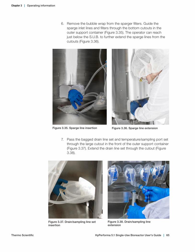
6. Remove the bubble wrap from the sparger filters. Guide the sparge inlet lines and filters through the bottom cutouts in the outer support container (Figure 3.35). The operator can reach just below the S.U.B. to further extend the sparge lines from the cutouts (Figure 3.36).
Figure 3.35. Sparge line insertion Figure 3.36. Sparge line extension
Figure 3.37. Drain/sampling line set insertion
Figure 3.38. Drain/sampling line extension
7. Pass the bagged drain line set and temperature/sampling port set through the large cutout in the front of the outer support container (Figure 3.37). Extend the drain line set through the cutout (Figure 3.38).
Chapter 3 | Operating information
Thermo Scientific HyPerforma 5.1 Single‑Use Bioreactor User's Guide | 65

8. Connect the pressure transducer to the monitor. After the display has stabilized, tare the monitor. The monitor should be allowed to warm up for 30 minutes before taring. Verify that the monitor reads zero.
9. The BPC must be partially inflated until it is sitting upright. This allows proper insertion of the drive shaft and aids in the proper alignment of the BPC in the outer support container.• Attach the air supply to the overlay gas inlet line. Note: Air
pressure to the overlay gas line on the S.U.B. BPC should not exceed 0.2 bar (3 psi) or 25 slpm.
• Begin air inflation through the overlay gas line. Filling the container with air takes approximately 15–20 minutes before drive shaft insertion can begin. Times will vary based upon flow rate and inlet pressure.
• Steps 10–13 can be completed while the BPC is filling with air.
WARNING: The BPC is not rated as a pressure vessel. DO NOT EXCEED 0.034 bar (0.5 psi) within the BPC or the system could fail, causing personal injury or damage to equipment. DO NOT leave the BPC unattended while inflating. See Table 3.7 in section 3.6.8 for recommended air flow rates. The operating pressures at the level of the S.U.B. are of primary importance and these values must be adhered to.
10. Attach the incoming gas supply to the sparger gas inlet line. Note: Air pressure to the sparger on the BPC should not exceed 0.55 bar (8 psi). Also, while a sparge line check valve is provided for each sparge line, some fluid may bypass check valves during typical use. Elevating the filter to ensure that it is not at the low point of the sparge line will reduce the chance that the filter is exposed to liquid.
11. Tare the load cell display before proceeding.
12. Attach all of the hanging tabs on the BPC to the hooks on the bottom of the outer support container to help position the ports (Figures 3.39 and 3.40). Verify that the sparger filter and spargers remain in the correct position. It is recommended that users secure the hanging tabs on the front BPC panel first. This way the door will not be an obstruction when connecting the last set of hooks.
Chapter 3 | Operating information
Thermo Scientific HyPerforma 5.1 Single‑Use Bioreactor User's Guide | 66
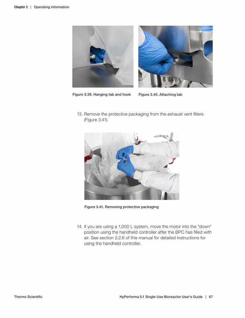
Figure 3.39. Hanging tab and hook Figure 3.40. Attaching tab
13. Remove the protective packaging from the exhaust vent filters (Figure 3.41).
Figure 3.41. Removing protective packaging
14. If you are using a 1,000 L system, move the motor into the "down" position using the handheld controller after the BPC has filled with air. See section 2.2.6 of this manual for detailed instructions for using the handheld controller.
Chapter 3 | Operating information
Thermo Scientific HyPerforma 5.1 Single‑Use Bioreactor User's Guide | 67

3.3.2 Drive shaft insertion for 500 L and 1,000 L systems
The drive shaft is constructed in multiple segments, which must be assembled and inserted in pieces. Operators should be elevated (i.e. ladder) to effectively assemble and insert the drive shaft. CAUTION: Review ceiling height requirements in Chapter 4 of this user's guide before trying to insert the drive shaft.
WARNING: Ensure that the correct drive shaft is being used for 500 L systems. Because the 5.1 S.U.B. is capable of mixing at much lower volumes than traditional 2.1 S.U.B.s, it is important to use the correct drive shaft to avoid damaging the hardware. 500 L 5.1 drive shaft heads are black and engraved with "5:1 Mixing." 2:1 mixing in 500 L S.U.B.s uses a system with a different impeller angle, and is covered in a separate S.U.B. user's guide. 1,000 L 5.1 systems use drive shafts with white heads that are NOT labeled for 5:1 mixing.
Figure 3.42 illustrates the components of the motor and mixing assembly. The parts labeled on the figure will be referenced throughout the drive shaft insertion process. Use the steps in this section to assemble and insert the drive shaft.
Motor cap
Drive shaft head
Motor drive keyway
Latch pin
Motor
Hollow pass-through
Safety cover
Drive shaft
Figure 3.42. Motor and mixing assembly
Chapter 3 | Operating information
Thermo Scientific HyPerforma 5.1 Single‑Use Bioreactor User's Guide | 68
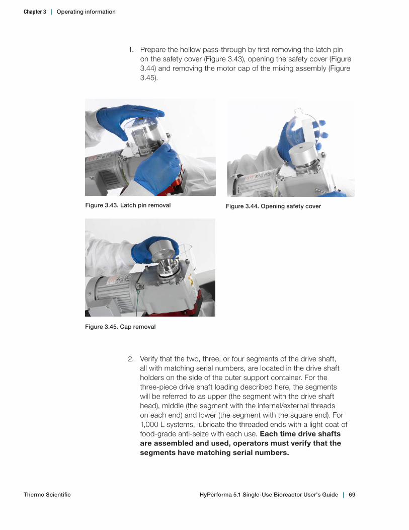
1. Prepare the hollow pass-through by first removing the latch pin on the safety cover (Figure 3.43), opening the safety cover (Figure 3.44) and removing the motor cap of the mixing assembly (Figure 3.45).
Figure 3.43. Latch pin removal
2. Verify that the two, three, or four segments of the drive shaft, all with matching serial numbers, are located in the drive shaft holders on the side of the outer support container. For the three-piece drive shaft loading described here, the segments will be referred to as upper (the segment with the drive shaft head), middle (the segment with the internal/external threads on each end) and lower (the segment with the square end). For 1,000 L systems, lubricate the threaded ends with a light coat of food-grade anti-seize with each use. Each time drive shafts are assembled and used, operators must verify that the segments have matching serial numbers.
Figure 3.45. Cap removal
Figure 3.44. Opening safety cover
Chapter 3 | Operating information
Thermo Scientific HyPerforma 5.1 Single‑Use Bioreactor User's Guide | 69

3. First, insert the lower segment through the hollow pass-through of the mixer drive (Figure 3.46). Slide the latch pin from the motor assembly into the shaft to prevent it from falling into the tube (Figure 3.47). Assemble the middle and lower segments of the drive shaft by joining them with a twisting motion, fastening the two segments together (Figure 3.48).
Note: Segmented shafts are left-threaded (reverse-threaded) to avoid loosening during operation.
Figure 3.46. Inserting lower section Figure 3.47. Latch pin in shaft
Figure 3.48. Segment assembly
Chapter 3 | Operating information
Thermo Scientific HyPerforma 5.1 Single‑Use Bioreactor User's Guide | 70
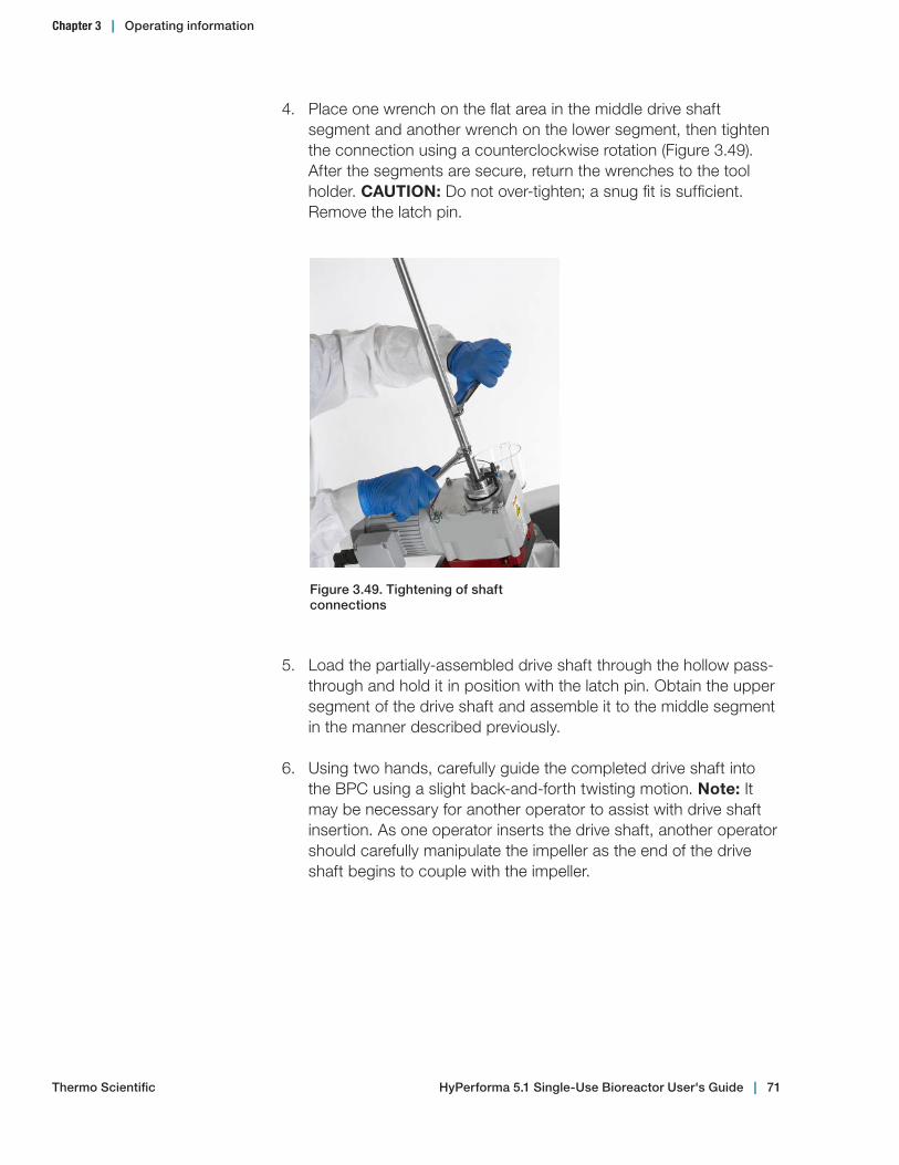
4. Place one wrench on the flat area in the middle drive shaft segment and another wrench on the lower segment, then tighten the connection using a counterclockwise rotation (Figure 3.49). After the segments are secure, return the wrenches to the tool holder. CAUTION: Do not over-tighten; a snug fit is sufficient. Remove the latch pin.
Figure 3.49. Tightening of shaft connections
5. Load the partially-assembled drive shaft through the hollow pass-through and hold it in position with the latch pin. Obtain the upper segment of the drive shaft and assemble it to the middle segment in the manner described previously.
6. Using two hands, carefully guide the completed drive shaft into the BPC using a slight back-and-forth twisting motion. Note: It may be necessary for another operator to assist with drive shaft insertion. As one operator inserts the drive shaft, another operator should carefully manipulate the impeller as the end of the drive shaft begins to couple with the impeller.
Chapter 3 | Operating information
Thermo Scientific HyPerforma 5.1 Single‑Use Bioreactor User's Guide | 71
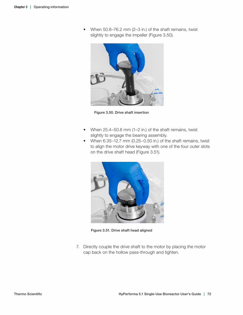
• When 50.8–76.2 mm (2–3 in.) of the shaft remains, twist slightly to engage the impeller (Figure 3.50).
Figure 3.50. Drive shaft insertion
Figure 3.51. Drive shaft head aligned
• When 25.4–50.8 mm (1–2 in.) of the shaft remains, twist slightly to engage the bearing assembly.
• When 6.35–12.7 mm (0.25–0.50 in.) of the shaft remains, twist to align the motor drive keyway with one of the four outer slots on the drive shaft head (Figure 3.51).
7. Directly couple the drive shaft to the motor by placing the motor cap back on the hollow pass-through and tighten.
Chapter 3 | Operating information
Thermo Scientific HyPerforma 5.1 Single‑Use Bioreactor User's Guide | 72
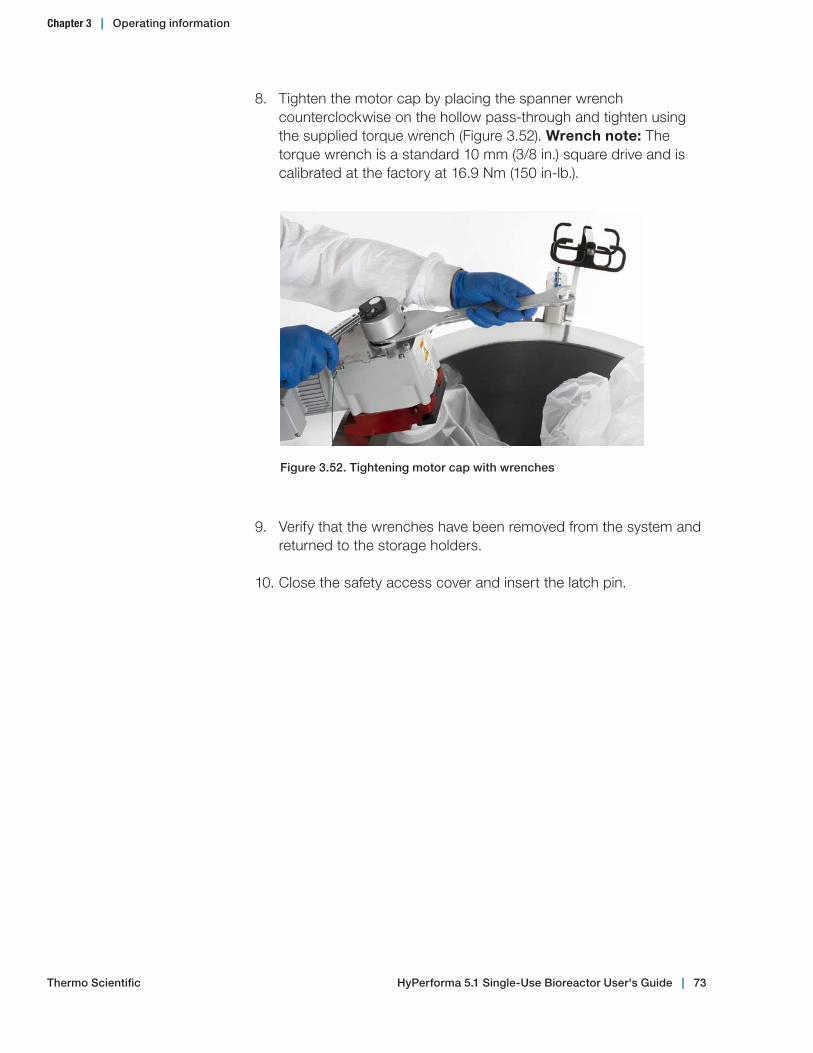
8. Tighten the motor cap by placing the spanner wrench counterclockwise on the hollow pass-through and tighten using the supplied torque wrench (Figure 3.52). Wrench note: The torque wrench is a standard 10 mm (3/8 in.) square drive and is calibrated at the factory at 16.9 Nm (150 in-lb.).
9. Verify that the wrenches have been removed from the system and returned to the storage holders.
10. Close the safety access cover and insert the latch pin.
Figure 3.52. Tightening motor cap with wrenches
Chapter 3 | Operating information
Thermo Scientific HyPerforma 5.1 Single‑Use Bioreactor User's Guide | 73

3.3.3 Final installation steps for 500 L and 1,000 L systems
1. Secure the exhaust vent filters to the top-mounted holders (Figure 3.53), or if you are using elevated dual exhaust filters, use the adapter piece and extended filter bracket (Figure 3.54). Note: 500 L BPCs and some custom BPCs are supplied with dual exhaust vents. The vent bracket can accommodate 10 in. and 4 in. filters in either single or dual configuration.
Figure 3.53. Vent filter Figure 3.54. Extended dual filter bracket
Figure 3.55. Aseptic connector port alignment
2. Fully extend the drain line set through the front cutout and attach the probe shelf.
3. Remove the polybag from the drain line set and position the line clamp as close as possible to the BPC port and close. Use a cable tie around the clamp to ensure the clamp does not open.
4. Align the aseptic connector ports through the front access window (Figure 3.55).
Chapter 3 | Operating information
Thermo Scientific HyPerforma 5.1 Single‑Use Bioreactor User's Guide | 74

5. Remove the plastic insert located in the thermowell, if present.
6. Insert the RTD or another selected temperature sensor into the thermowell (Figure 3.56).
• Place a small amount of glycerol (0.5 mL) in the thermowell to aid in heat transfer. The glycerol also serves as a lubricant and aids in insertion.
• The sensor should be inserted until the base of the RTD meets the mouth of the thermowell.
• Secure by twisting the luer lock collar, if provided; the thermowell will stretch slightly when the RTD is seated (Figure 3.57).
Note: Verify that all port clamps are closed and located as close as possible to the body of the BPC.
Figure 3.56. Temperature sensor insertion
Figure 3.57. Securing temperature sensor
Chapter 3 | Operating information
Thermo Scientific HyPerforma 5.1 Single‑Use Bioreactor User's Guide | 75

Figure 3.58. Latching the access door
Safety pin pass-through of latch set
Latch retainer
7. Optional: Connect a pressure sensor to the CPC aseptic connector at the top of the BPC. Then connect the appropriate pressure transducer cable to the third-party controller.
8. Refer to section 3.5.3 for probe insertion instructions.
9. Close the bottom access door. The proper latch tension can be obtained by a combination of feel and visual inspection. When closing the latch, the handle should begin to provide resistance to closing when the leading edge of the safety pin pass-through of the latch handle aligns with the outside edge of the latch base (Figure 3.58). Note: When the latch is under-tensioned, the safety pin pass-through of the latch handle will be covered within the latch base and the handle will close very easily. If the latch is over-tensioned, the handle will be excessively difficult to close.
10. The access doors must be closed and fully latched prior to filling the system with liquid.
Chapter 3 | Operating information
Thermo Scientific HyPerforma 5.1 Single‑Use Bioreactor User's Guide | 76

3.4 BPC and drive shaft loading, and condenser system setup instructions for 2,000 L systems
3.4.1 Initial BPC loading steps for 2,000 L systems
Checkpoints prior to BPC loading 9 The correct volume BPC is being used for the corresponding
volume outer support container. 9 The motor is in the "up" position. For information on using the
handheld controller for motor lifts, see section 2.2.6. 9 The BPC lift control is plugged into a 120–240 VAC receptacle,
and the Main Disconnect and Motor Enable switches on the BPC lift control are switched to "off."
9 Three operators are available for ease in BPC loading. 9 A ladder or other means of elevation is available for drive shaft
insertion (See the specifications in Chapter 4 for system ceiling height requirements).
9 The equipment has been evaluated against your confined space safety standards and procedures.
Use the following steps to install and set up the BPC.
1. Switch on the main power to the control panel. Ensure that the drive motor is not running. Open both the front and rear doors on the outer support container.
2. Verify that the motor area is clear and the Vertical Lift switch on the BPC lift control (located on the side of the S.U.B.) is in the "up" position. Then flip the Motor Enable switch on the BPC lift control to the "on" position. The BPC lift should perform a homing operation, which fully raises the wires to the hard stop of the support arms before lowering them to the "up" position.• CAUTION: Keep hands clear during the homing operation. • The homing operation is complete when the lift stops moving.
3. Before lowering the BPC lift, ensure that the S.U.B. area is clear. Do not lower the BPC lift if there are any obstructions. Flip the Vertical Lift switch down to lower the BPC lift hooks.
Chapter 3 | Operating information
Thermo Scientific HyPerforma 5.1 Single‑Use Bioreactor User's Guide | 77
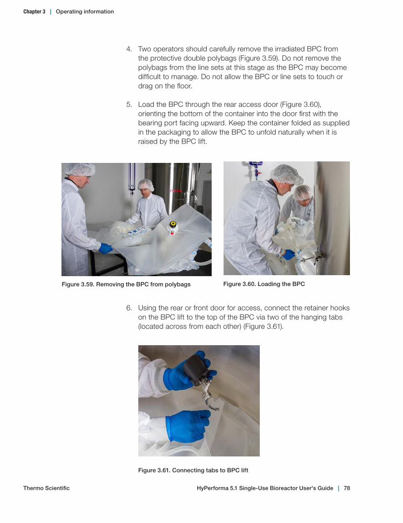
4. Two operators should carefully remove the irradiated BPC from the protective double polybags (Figure 3.59). Do not remove the polybags from the line sets at this stage as the BPC may become difficult to manage. Do not allow the BPC or line sets to touch or drag on the floor.
5. Load the BPC through the rear access door (Figure 3.60), orienting the bottom of the container into the door first with the bearing port facing upward. Keep the container folded as supplied in the packaging to allow the BPC to unfold naturally when it is raised by the BPC lift.
6. Using the rear or front door for access, connect the retainer hooks on the BPC lift to the top of the BPC via two of the hanging tabs (located across from each other) (Figure 3.61).
Figure 3.61. Connecting tabs to BPC lift
Figure 3.60. Loading the BPCFigure 3.59. Removing the BPC from polybags
Chapter 3 | Operating information
Thermo Scientific HyPerforma 5.1 Single‑Use Bioreactor User's Guide | 78
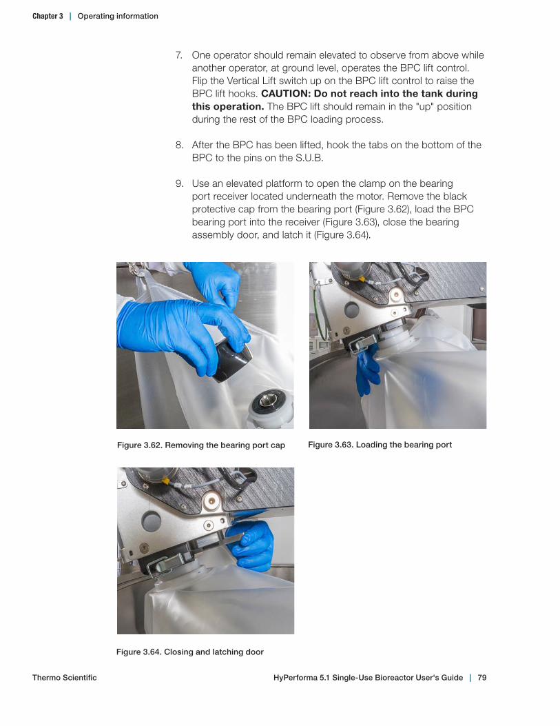
7. One operator should remain elevated to observe from above while another operator, at ground level, operates the BPC lift control. Flip the Vertical Lift switch up on the BPC lift control to raise the BPC lift hooks. CAUTION: Do not reach into the tank during this operation. The BPC lift should remain in the "up" position during the rest of the BPC loading process.
8. After the BPC has been lifted, hook the tabs on the bottom of the BPC to the pins on the S.U.B.
9. Use an elevated platform to open the clamp on the bearing port receiver located underneath the motor. Remove the black protective cap from the bearing port (Figure 3.62), load the BPC bearing port into the receiver (Figure 3.63), close the bearing assembly door, and latch it (Figure 3.64).
Figure 3.63. Loading the bearing port
Figure 3.64. Closing and latching door
Figure 3.62. Removing the bearing port cap
Chapter 3 | Operating information
Thermo Scientific HyPerforma 5.1 Single‑Use Bioreactor User's Guide | 79

10. Place the top line sets (still in polybags) over the side of the outer support container (Figure 3.65). This will help support the weight of the BPC and also keep the BPC from being restricted during the air inflation step.
Figure 3.65. Placing linesets over tank edge
11. If your BPC includes exhaust vent filters, ensure that they are lifted through the middle of the motor lift instead of to either side. This will ensure the exhaust vent filters are properly oriented. If you are using the exhaust condenser system, follow the setup instructions in section 3.4.2 of this guide. If you are using elevated exhaust vent filters, use the corresponding extended dual vent filter bracket and filter heaters.
To load the optional exhaust vent filters, follow the steps below.
• Clip each filter one at a time into the elevated vent filter holder system (Figure 3.66). Carefully center the filter housing, allowing the clip to secure it near the hose barb connections.
Figure 3.66. Clipping filter to holder
Thermo Scientific
Chapter 3 | Operating information
HyPerforma 5.1 Single‑Use Bioreactor User's Guide | 80
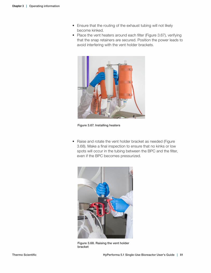
• Ensure that the routing of the exhaust tubing will not likely become kinked.
• Place the vent heaters around each filter (Figure 3.67), verifying that the snap retainers are secured. Position the power leads to avoid interfering with the vent holder brackets.
Figure 3.67. Installing heaters
• Raise and rotate the vent holder bracket as needed (Figure 3.68). Make a final inspection to ensure that no kinks or low spots will occur in the tubing between the BPC and the filter, even if the BPC becomes pressurized.
Figure 3.68. Raising the vent holder bracket
Thermo Scientific
Chapter 3 | Operating information
HyPerforma 5.1 Single‑Use Bioreactor User's Guide | 81

• Connect the power to the vent heaters and verify operation of the controllers.
• Inspect the controllers' setpoints (recommended 60°C). After two to five minutes of operation, verify that the vent heaters are warm and are near the desired temperature setpoints. Verify that no alarm indicators are active.
12. Open the tubing set polybag and connect the pressure transducer to the monitor. Once the display has stabilized, tare the monitor. The monitor should be allowed to warm up for 30 minutes and the sensor connected for 10 minutes before taring. Verify that the monitor reads zero.
13. Clamp the drilled hole sparge, exhaust, and cross flow lines so that the air supplied by the overlay gas inlet line flows directly into the BPC (Figure 3.69).
Figure 3.69. Clamping the exhaust lines prior to filling the BPC with air
14. The BPC must be partially inflated to aid in the proper alignment of the BPC in the outer support container, and proper insertion of the drive shaft. • Attach the air supply to the overlay gas inlet line at the top of
the BPC. • Begin filling the BPC with air. Operators should allow the
container to fill to greater than half volume. This typically takes less than 20 minutes.
• Steps 15–18 can be completed while the BPC is filling with air.
Note: Air pressure to the overlay gas line on the BPC should not exceed 0.344 bar (5 psi) or 100 slpm.
Thermo Scientific
Chapter 3 | Operating information
HyPerforma 5.1 Single‑Use Bioreactor User's Guide | 82

16. Remove the sparge lines from the polybags and bubble wrap from the sparge filters. Use the rear door to gain inside access to the floor of the hardware. Place a clamp on the bottom drain line at this time (Figure 3.71).
WARNING: The BPC is not rated as a pressure vessel. DO NOT EXCEED 0.034 bar (0.5 psi) within the BPC or the system could fail, causing personal injury or damage to equipment. DO NOT leave the BPC unattended while inflating. See Table 3.7 in section 3.6.8 for recommended air flow rates. The operating pressures at the level of the S.U.B. are of primary importance and these values must be adhered to.
15. Feed the probe belt, sample line, and the subsurface addition lines through the front access door (Figure 3.70).
Figure 3.70. Feeding lines through the front access door
Figure 3.71. Clamping bottom drain line
Chapter 3 | Operating information
Thermo Scientific HyPerforma 5.1 Single‑Use Bioreactor User's Guide | 83
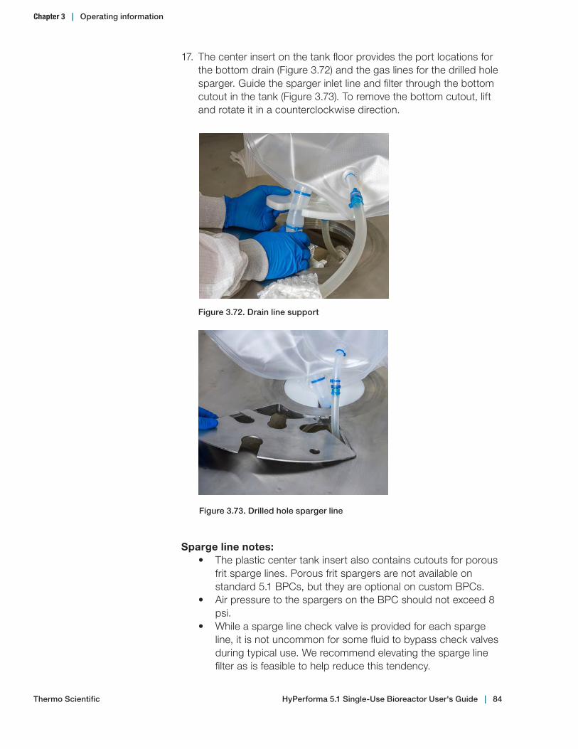
17. The center insert on the tank floor provides the port locations for the bottom drain (Figure 3.72) and the gas lines for the drilled hole sparger. Guide the sparger inlet line and filter through the bottom cutout in the tank (Figure 3.73). To remove the bottom cutout, lift and rotate it in a counterclockwise direction.
Sparge line notes:• The plastic center tank insert also contains cutouts for porous
frit sparge lines. Porous frit spargers are not available on standard 5.1 BPCs, but they are optional on custom BPCs.
• Air pressure to the spargers on the BPC should not exceed 8 psi.
• While a sparge line check valve is provided for each sparge line, it is not uncommon for some fluid to bypass check valves during typical use. We recommend elevating the sparge line filter as is feasible to help reduce this tendency.
Figure 3.72. Drain line support
Figure 3.73. Drilled hole sparger line
Chapter 3 | Operating information
Thermo Scientific HyPerforma 5.1 Single‑Use Bioreactor User's Guide | 84
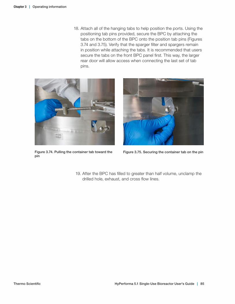
19. After the BPC has filled to greater than half volume, unclamp the drilled hole, exhaust, and cross flow lines.
Figure 3.74. Pulling the container tab toward the pin
Figure 3.75. Securing the container tab on the pin
18. Attach all of the hanging tabs to help position the ports. Using the positioning tab pins provided, secure the BPC by attaching the tabs on the bottom of the BPC onto the position tab pins (Figures 3.74 and 3.75). Verify that the sparger filter and spargers remain in position while attaching the tabs. It is recommended that users secure the tabs on the front BPC panel first. This way, the larger rear door will allow access when connecting the last set of tab pins.
Chapter 3 | Operating information
Thermo Scientific HyPerforma 5.1 Single‑Use Bioreactor User's Guide | 85
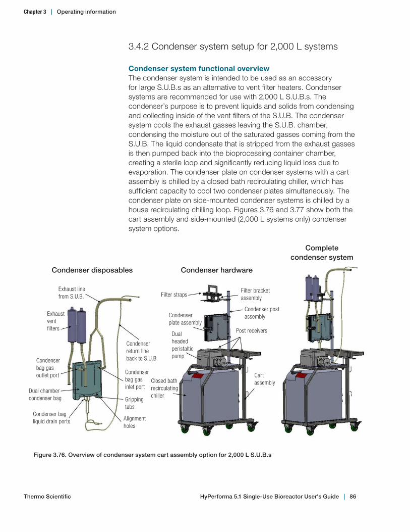
3.4.2 Condenser system setup for 2,000 L systems
Condenser system functional overviewThe condenser system is intended to be used as an accessory for large S.U.B.s as an alternative to vent filter heaters. Condenser systems are recommended for use with 2,000 L S.U.B.s. The condenser’s purpose is to prevent liquids and solids from condensing and collecting inside of the vent filters of the S.U.B. The condenser system cools the exhaust gasses leaving the S.U.B. chamber, condensing the moisture out of the saturated gasses coming from the S.U.B. The liquid condensate that is stripped from the exhaust gasses is then pumped back into the bioprocessing container chamber, creating a sterile loop and significantly reducing liquid loss due to evaporation. The condenser plate on condenser systems with a cart assembly is chilled by a closed bath recirculating chiller, which has sufficient capacity to cool two condenser plates simultaneously. The condenser plate on side-mounted condenser systems is chilled by a house recirculating chilling loop. Figures 3.76 and 3.77 show both the cart assembly and side-mounted (2,000 L systems only) condenser system options.
Figure 3.76. Overview of condenser system cart assembly option for 2,000 L S.U.B.s
Exhaust line from S.U.B.
Exhaust vent filters
Condenser bag gas outlet port
Dual chamber condenser bag
Condenser return line back to S.U.B.
Condenser bag gas inlet port
Dual headed peristaltic pump
Closed bath recirculating chiller
Condenser plate assembly
Filter straps
Gripping tabs
Alignment holes
Filter bracket assembly
Condenser post assembly
Post receivers
Cart assembly
Condenser bag liquid drain ports
Condenser disposables Condenser hardware
Complete condenser system
Chapter 3 | Operating information
Thermo Scientific HyPerforma 5.1 Single‑Use Bioreactor User's Guide | 86
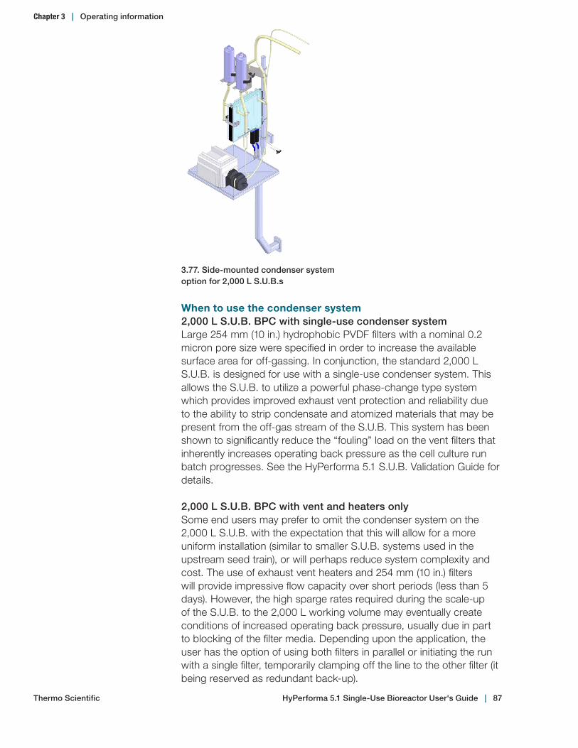
When to use the condenser system2,000 L S.U.B. BPC with single‑use condenser systemLarge 254 mm (10 in.) hydrophobic PVDF filters with a nominal 0.2 micron pore size were specified in order to increase the available surface area for off-gassing. In conjunction, the standard 2,000 L S.U.B. is designed for use with a single-use condenser system. This allows the S.U.B. to utilize a powerful phase-change type system which provides improved exhaust vent protection and reliability due to the ability to strip condensate and atomized materials that may be present from the off-gas stream of the S.U.B. This system has been shown to significantly reduce the “fouling” load on the vent filters that inherently increases operating back pressure as the cell culture run batch progresses. See the HyPerforma 5.1 S.U.B. Validation Guide for details.
2,000 L S.U.B. BPC with vent and heaters onlySome end users may prefer to omit the condenser system on the 2,000 L S.U.B. with the expectation that this will allow for a more uniform installation (similar to smaller S.U.B. systems used in the upstream seed train), or will perhaps reduce system complexity and cost. The use of exhaust vent heaters and 254 mm (10 in.) filters will provide impressive flow capacity over short periods (less than 5 days). However, the high sparge rates required during the scale-up of the S.U.B. to the 2,000 L working volume may eventually create conditions of increased operating back pressure, usually due in part to blocking of the filter media. Depending upon the application, the user has the option of using both filters in parallel or initiating the run with a single filter, temporarily clamping off the line to the other filter (it being reserved as redundant back-up).
3.77. Side‑mounted condenser system option for 2,000 L S.U.B.s
Chapter 3 | Operating information
Thermo Scientific HyPerforma 5.1 Single‑Use Bioreactor User's Guide | 87
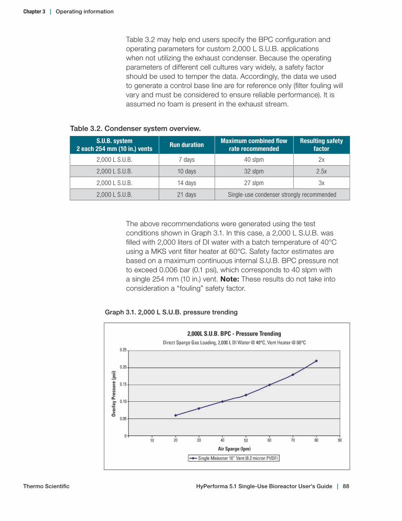
Table 3.2 may help end users specify the BPC configuration and operating parameters for custom 2,000 L S.U.B. applications when not utilizing the exhaust condenser. Because the operating parameters of different cell cultures vary widely, a safety factor should be used to temper the data. Accordingly, the data we used to generate a control base line are for reference only (filter fouling will vary and must be considered to ensure reliable performance). It is assumed no foam is present in the exhaust stream.
Table 3.2. Condenser system overview.
S.U.B. system 2 each 254 mm (10 in.) vents
Run durationMaximum combined flow
rate recommendedResulting safety
factor
2,000 L S.U.B. 7 days 40 slpm 2x
2,000 L S.U.B. 10 days 32 slpm 2.5x
2,000 L S.U.B. 14 days 27 slpm 3x
2,000 L S.U.B. 21 days Single-use condenser strongly recommended
The above recommendations were generated using the test conditions shown in Graph 3.1. In this case, a 2,000 L S.U.B. was filled with 2,000 liters of DI water with a batch temperature of 40°C using a MKS vent filter heater at 60°C. Safety factor estimates are based on a maximum continuous internal S.U.B. BPC pressure not to exceed 0.006 bar (0.1 psi), which corresponds to 40 slpm with a single 254 mm (10 in.) vent. Note: These results do not take into consideration a “fouling” safety factor.
Graph 3.1. 2,000 L S.U.B. pressure trending
Thermo Scientific
Chapter 3 | Operating information
HyPerforma 5.1 Single‑Use Bioreactor User's Guide | 88

Also consider the size and type of tubing used to connect the exhaust vents to the S.U.B. BPC (when not using an exhaust condenser). Braid reinforced tubing provides the best protection against kinking or accidental pinching of the exhaust line. The 254 mm (10 in.) vents are supplied with 19.1 mm (0.75 in.) hose barbs and this tubing diameter will allow condensate to return to the S.U.B. at total off-gas flow rates up to 30 slpm (assuming the tubing is near a vertical orientation). Testing has shown that large diameter tubing will allow for lower exhaust gas velocities and if the vapor velocity is below 0.6 m/s (1.96 ft./s), gravity will allow the condensate formed in the tubing to return to the batch process (Graph 3.2).
Note: Restrictive tubing connectors can create flow bottle necks and 12.7 mm (0.5 in.) inner diameter (ID) tubing is typically deemed too small for the 2,000 L S.U.B.
Graph 3.2. Tubing diameter recommendation
Thermo Scientific
Chapter 3 | Operating information
HyPerforma 5.1 Single‑Use Bioreactor User's Guide | 89

Various vent filter configurations are available on the S.U.B. depending upon the process scale and intended application. Graph 3.3 provides a reference for determining the relative capacity of different filters depending upon the amount of gas flow anticipated and the length of the run. In all cases, using a vent filter heater will reduce the chance of condensate blocking the filter, but over time, suspended solids carried in the exhaust stream will impede the flow of exhaust gas (resulting in increased back pressure). In addition, it is good practice to monitor the amount of foam present in the head space. In all cases, a vent filter heater has very little tolerance for handling the presence of foam in the exhaust stream. A small feed of antifoam (e.g., FoamAway™ Irradiated AOF Antifoaming Agent, catalog number A1036901) added directly to the liquid surface of the culture head space typically provides excellent foam control. 1,000 L and 2,000 L systems can benefit from the use of a condenser system. It has been shown to increase system reliability at high flow rates (beyond 50 slpm) and should warrant strong consideration when performing batch runs beyond 10 days. Results will vary; however, it is strongly recommended that end users select a vent filter configuration providing reserve capacity where possible. For example, dual vent configurations can be used independently with the second filter serving as a redundant backup (providing a quick reserve in case issues arise in process).
Graph 3.3. Off‑gassing management guidelines
Thermo Scientific
Chapter 3 | Operating information
HyPerforma 5.1 Single‑Use Bioreactor User's Guide | 90

Condenser system setup1. Remove the reservoir cap of the chiller and add the appropriate
type and volume of fluid as per the chiller user's guide.
2. Verify that the peristaltic pump and chiller power cords are connected to a power source.
3. If you are using a condenser system with a cart assembly, plug in the system.
4. Turn on the power to the chiller. This will allow the chiller to prime.
5. If you are using a temperature control unit (TCU), ensure that the TCU coolant is filled to the maximum level.
CAUTION: Low TCU coolant levels can increase the temperature of the plates, and cause excessive pressure and/or residue buildup in the condenser bag. Please note that the chiller plates may run warmer than the TCU setpoint.
6. Purge the chill plate by loosening the bleed plug on top of the plate. This is accessed using a hex wrench passing through the top tensioning plate of the chill plate assembly. Loosen the plug only enough to allow trapped air to escape, then re-tighten.
7. The settings for the chiller and peristaltic pump are preset at the factory. These settings allow for the system to resume setpoint if the power is temporarily disrupted. Verify that the chiller and pump setpoints are at the recommended levels (5°C and 12 rpm).
8. If you are using a condenser system with a cart assembly, verify that the peristaltic pump is in place on the cart beneath the chill plate. Side-mounted condenser systems have an attached tray for the peristaltic pump.
Chapter 3 | Operating information
Thermo Scientific HyPerforma 5.1 Single‑Use Bioreactor User's Guide | 91
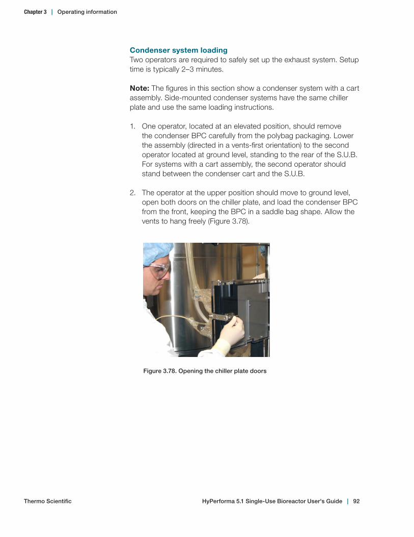
Condenser system loadingTwo operators are required to safely set up the exhaust system. Setup time is typically 2–3 minutes.
Note: The figures in this section show a condenser system with a cart assembly. Side-mounted condenser systems have the same chiller plate and use the same loading instructions.
1. One operator, located at an elevated position, should remove the condenser BPC carefully from the polybag packaging. Lower the assembly (directed in a vents-first orientation) to the second operator located at ground level, standing to the rear of the S.U.B. For systems with a cart assembly, the second operator should stand between the condenser cart and the S.U.B.
2. The operator at the upper position should move to ground level, open both doors on the chiller plate, and load the condenser BPC from the front, keeping the BPC in a saddle bag shape. Allow the vents to hang freely (Figure 3.78).
Figure 3.78. Opening the chiller plate doors
Chapter 3 | Operating information
Thermo Scientific HyPerforma 5.1 Single‑Use Bioreactor User's Guide | 92
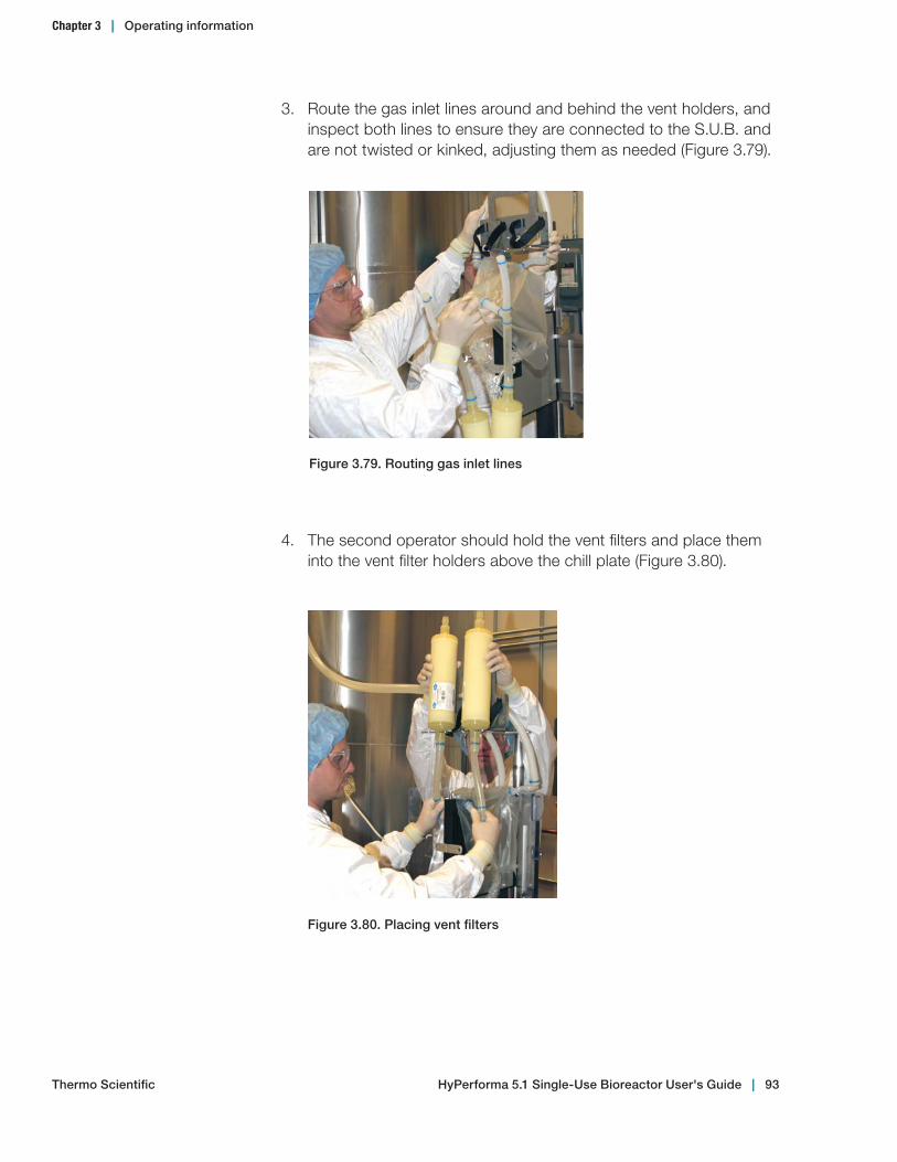
4. The second operator should hold the vent filters and place them into the vent filter holders above the chill plate (Figure 3.80).
Figure 3.79. Routing gas inlet lines
3. Route the gas inlet lines around and behind the vent holders, and inspect both lines to ensure they are connected to the S.U.B. and are not twisted or kinked, adjusting them as needed (Figure 3.79).
Figure 3.80. Placing vent filters
Chapter 3 | Operating information
Thermo Scientific HyPerforma 5.1 Single‑Use Bioreactor User's Guide | 93

6. Use the grasping tabs to position the container using the two lower button pins on each side of the chiller plate (Figure 3.82).
Figure 3.81. Securing vent filters
5. The first operator should use the Velcro™ straps to secure the filters in position (Figure 3.81).
Figure 3.82. Positioning container
Chapter 3 | Operating information
Thermo Scientific HyPerforma 5.1 Single‑Use Bioreactor User's Guide | 94
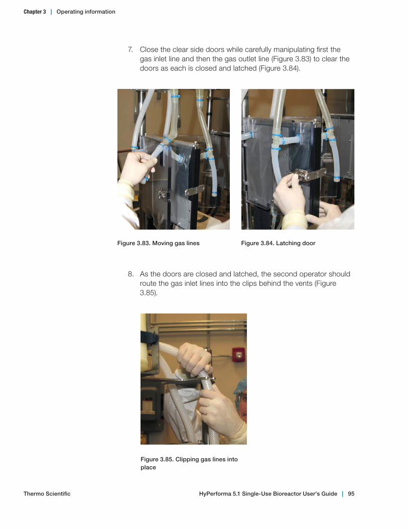
8. As the doors are closed and latched, the second operator should route the gas inlet lines into the clips behind the vents (Figure 3.85).
7. Close the clear side doors while carefully manipulating first the gas inlet line and then the gas outlet line (Figure 3.83) to clear the doors as each is closed and latched (Figure 3.84).
Figure 3.84. Latching doorFigure 3.83. Moving gas lines
Figure 3.85. Clipping gas lines into place
Chapter 3 | Operating information
Thermo Scientific HyPerforma 5.1 Single‑Use Bioreactor User's Guide | 95
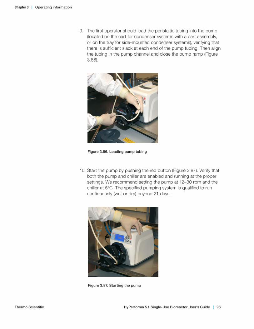
10. Start the pump by pushing the red button (Figure 3.87). Verify that both the pump and chiller are enabled and running at the proper settings. We recommend setting the pump at 12–30 rpm and the chiller at 5°C. The specified pumping system is qualified to run continuously (wet or dry) beyond 21 days.
9. The first operator should load the peristaltic tubing into the pump (located on the cart for condenser systems with a cart assembly, or on the tray for side-mounted condenser systems), verifying that there is sufficient slack at each end of the pump tubing. Then align the tubing in the pump channel and close the pump ramp (Figure 3.86).
Figure 3.86. Loading pump tubing
Figure 3.87. Starting the pump
Chapter 3 | Operating information
Thermo Scientific HyPerforma 5.1 Single‑Use Bioreactor User's Guide | 96

11. After setup, verify the following: 9 The elbow fittings on the inlet and outlet of the condenser
saddle bag are straight and level. 9 The gas inlet line and the condensate line are not twisted,
pinched, or obstructed. 9 There are no low spots in the gas inlet line. Adjust the lines to
avoid condensation pooling. 9 The pump union is loose on both ends of the pump and
running smoothly in the peristaltic rollers.
Contact technical support for specific condenser system performance questions.
3.4.3 Drive shaft insertion for 2,000 L systems
The new drive shafts for 2,000 L S.U.B.s are slightly longer and have black drive shaft heads. Thermo Fisher Scientific has redesigned the impeller in all standard 2,000 L S.U.B. BPCs to improve impeller engagement with this new drive shaft design. 2,000 L 5.1 BPCs are shipped with a hanging tag on the bearing port showing the required drive shaft length (Figure 3.88).
Figure 3.88. Close‑up view of 2,000 L 5.1 BPC hanging tag
Chapter 3 | Operating information
Thermo Scientific HyPerforma 5.1 Single‑Use Bioreactor User's Guide | 97
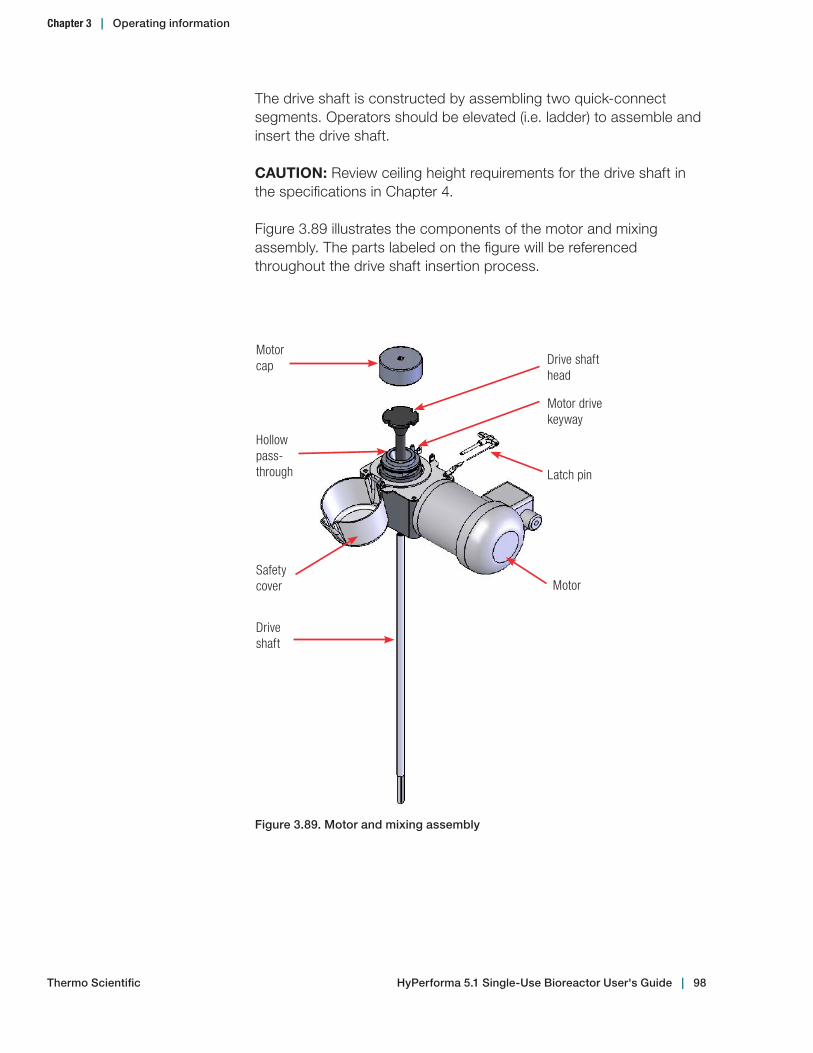
The drive shaft is constructed by assembling two quick-connect segments. Operators should be elevated (i.e. ladder) to assemble and insert the drive shaft.
CAUTION: Review ceiling height requirements for the drive shaft in the specifications in Chapter 4.
Figure 3.89 illustrates the components of the motor and mixing assembly. The parts labeled on the figure will be referenced throughout the drive shaft insertion process.
Motor cap Drive shaft
head
Motor drive keyway
Latch pin
Motor
Hollow pass-through
Safety cover
Drive shaft
Figure 3.89. Motor and mixing assembly
Chapter 3 | Operating information
Thermo Scientific HyPerforma 5.1 Single‑Use Bioreactor User's Guide | 98
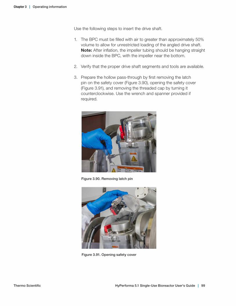
Use the following steps to insert the drive shaft.
1. The BPC must be filled with air to greater than approximately 50% volume to allow for unrestricted loading of the angled drive shaft. Note: After inflation, the impeller tubing should be hanging straight down inside the BPC, with the impeller near the bottom.
2. Verify that the proper drive shaft segments and tools are available.
3. Prepare the hollow pass-through by first removing the latch pin on the safety cover (Figure 3.90), opening the safety cover (Figure 3.91), and removing the threaded cap by turning it counterclockwise. Use the wrench and spanner provided if required.
Figure 3.91. Opening safety cover
Figure 3.90. Removing latch pin
HyPerforma 5.1 Single‑Use Bioreactor User's Guide | 99Thermo Scientific
Chapter 3 | Operating information

4. Verify that the two segments of the drive shaft have matching serial numbers, and are located in the drive shaft holders on the side of the outer support container. Important notes: Each time drive shafts are assembled and used in the S.U.B., operators must verify that the segments have matching serial numbers. No lubrication is required with the quick-connect assembly design.
5. First, insert the lower segment through the hollow pass-through of the mixer drive (Figure 3.92). Once inserted, slide the latch pin from the mixing assembly into the shaft to prevent it from falling into the impeller sleeve (tube) (Figure 3.93).
Figure 3.93. Use of the latch pinFigure 3.92. Insertion of the lower section of the drive shaft
6. To connect the upper and lower sections together, depress the button on the female side (Figure 3.94) and slide the sleeve back. This will expose a red ring underneath the sleeve (Figure 3.95). This is a visual indicator that the sleeve is not in a locked position.
Figure 3.95. Sliding sleeve exposing red "not locked" indicator
Figure 3.94. Button used for connection
Chapter 3 | Operating information
Thermo Scientific HyPerforma 5.1 Single‑Use Bioreactor User's Guide | 100

7. Place the female side of the quick-connect over the male end (Figure 3.96). The connection is fully seated when the red indicator ring (Figure 3.97) on the male end is no longer exposed.
8. Slide the sleeve toward the connection, allowing the push button to lock into position. This will engage the locking mechanism and also cover the red indicator ring (Figure 3.98). Note: When fully connected, no red coloring should be visible.
Figure 3.97. Red indicator ring exposedFigure 3.96. Quick connection
Figure 3.98. Sliding the sleeve into place
9. Once the sections are secure, remove the latch pin and return the wrenches to the tool holder.
10. Using two hands, carefully guide the completed drive shaft into the BPC using a slight back-and-forth twisting motion or a counterclockwise rotation (Figure 3.99). Do not push the drive shaft straight in.
Chapter 3 | Operating information
Thermo Scientific HyPerforma 5.1 Single‑Use Bioreactor User's Guide | 101
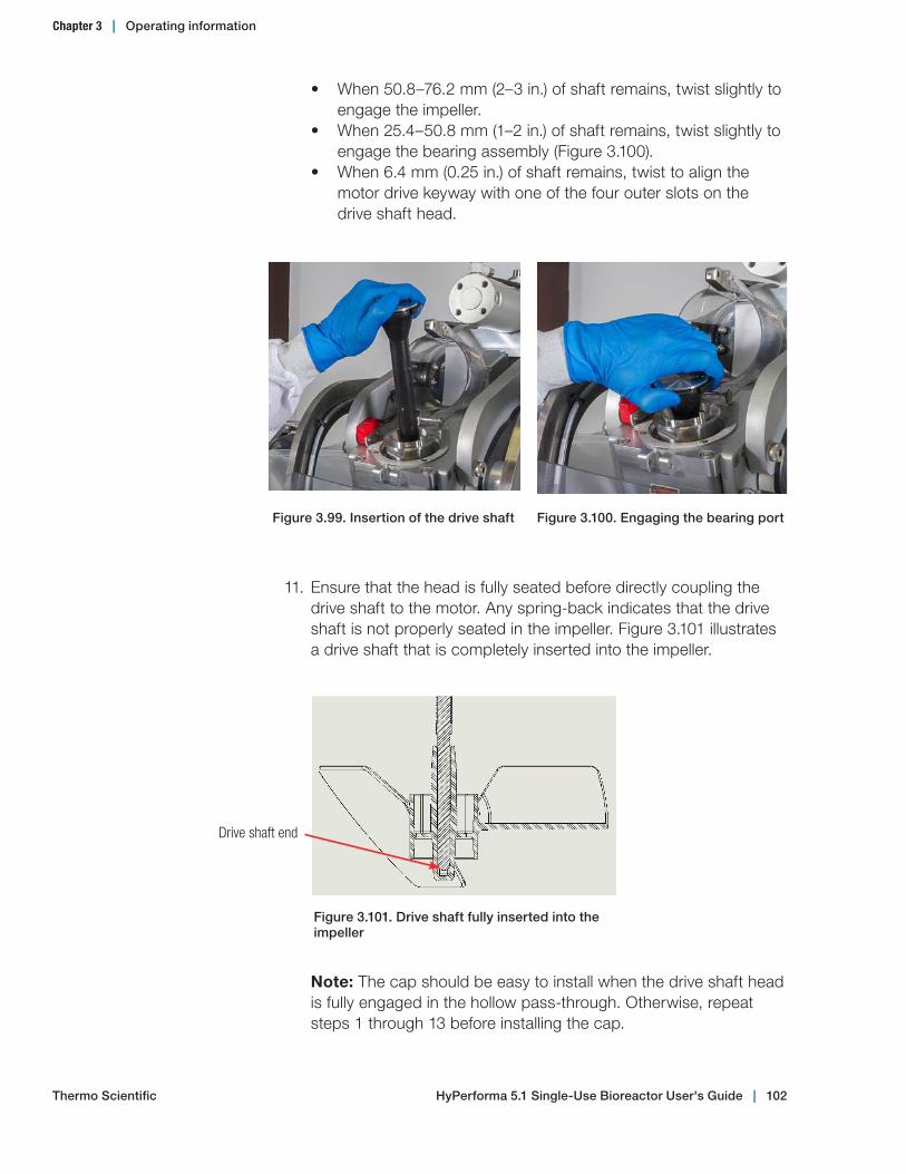
• When 50.8–76.2 mm (2–3 in.) of shaft remains, twist slightly to engage the impeller.
• When 25.4–50.8 mm (1–2 in.) of shaft remains, twist slightly to engage the bearing assembly (Figure 3.100).
• When 6.4 mm (0.25 in.) of shaft remains, twist to align the motor drive keyway with one of the four outer slots on the drive shaft head.
11. Ensure that the head is fully seated before directly coupling the drive shaft to the motor. Any spring-back indicates that the drive shaft is not properly seated in the impeller. Figure 3.101 illustrates a drive shaft that is completely inserted into the impeller.
Figure 3.99. Insertion of the drive shaft Figure 3.100. Engaging the bearing port
Figure 3.101. Drive shaft fully inserted into the impeller
Drive shaft end
Note: The cap should be easy to install when the drive shaft head is fully engaged in the hollow pass-through. Otherwise, repeat steps 1 through 13 before installing the cap.
Chapter 3 | Operating information
Thermo Scientific HyPerforma 5.1 Single‑Use Bioreactor User's Guide | 102
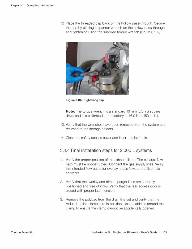
12. Place the threaded cap back on the hollow pass-through. Secure the cap by placing a spanner wrench on the hollow pass-through and tightening using the supplied torque wrench (Figure 3.102).
Note: The torque wrench is a standard 10 mm (3/8 in.) square drive, and it is calibrated at the factory at 16.9 Nm (150 in-lb.).
13. Verify that the wrenches have been removed from the system and returned to the storage holders.
14. Close the safety access cover and insert the latch pin.
3.4.4 Final installation steps for 2,000 L systems
1. Verify the proper position of the exhaust filters. The exhaust flow path must be unobstructed. Connect the gas supply lines. Verify the intended flow paths for overlay, cross flow, and drilled hole spargers.
2. Verify that the overlay and direct sparger lines are correctly positioned and free of kinks. Verify that the rear access door is closed with proper latch tension.
3. Remove the polybag from the drain line set and verify that the redundant line clamps are in position. Use a cable tie around the clamp to ensure the clamp cannot be accidentally opened.
Figure 3.102. Tightening cap
Chapter 3 | Operating information
Thermo Scientific HyPerforma 5.1 Single‑Use Bioreactor User's Guide | 103

4. Align the aseptic ports through the front access window (Figure 3.103).
Figure 3.103. Aseptic port alignment
5. Secure the access doors with the latches. Proper tension is obtained by adjusting the threaded latch pin. Tension of the latch is adjusted by varying the position of the pin on the threaded shank. The proper latch tension can be obtained by a combination of feel and visual inspection. When closing the latch, the handle should begin to provide resistance to closing when the leading edge of the safety pin pass-through of the latch handle aligns with the outside edge of the latch base. (Figure 3.104).
Note: When the latch is under-tensioned, the safety pin pass-through of the latch handle will be covered within the latch base and the handle will close very easily. If the latch is over-tensioned, the handle will be excessively difficult to close.
Figure 3.104. Latch access door
Outside edge of latch base
Safety pin pass-through of latch set
Latch retainer
Safety pin pass-through of latch-handle
Chapter 3 | Operating information
Thermo Scientific HyPerforma 5.1 Single‑Use Bioreactor User's Guide | 104
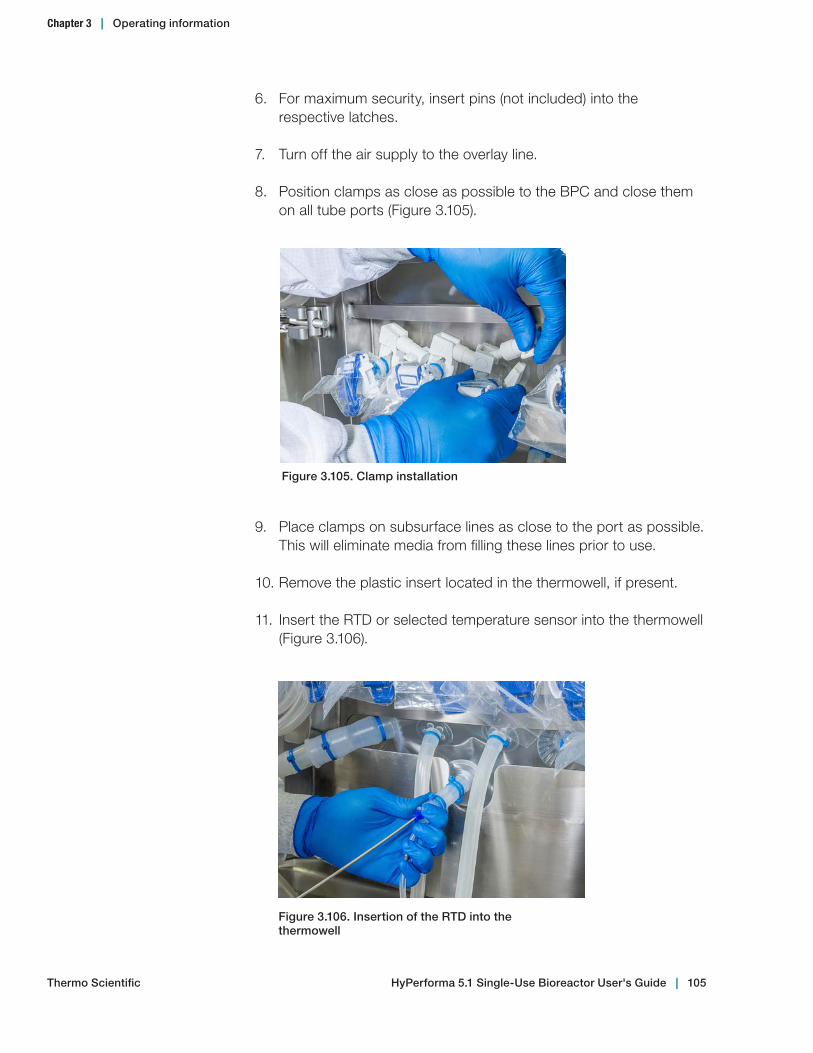
9. Place clamps on subsurface lines as close to the port as possible. This will eliminate media from filling these lines prior to use.
10. Remove the plastic insert located in the thermowell, if present.
11. Insert the RTD or selected temperature sensor into the thermowell (Figure 3.106).
6. For maximum security, insert pins (not included) into the respective latches.
7. Turn off the air supply to the overlay line.
8. Position clamps as close as possible to the BPC and close them on all tube ports (Figure 3.105).
Figure 3.105. Clamp installation
Figure 3.106. Insertion of the RTD into the thermowell
Chapter 3 | Operating information
Thermo Scientific HyPerforma 5.1 Single‑Use Bioreactor User's Guide | 105

• Place a small amount (0.5 mL) of glycerol (Sigma-Aldrich™ G6279) in the thermowell to aid in heat transfer.
• The sensor should be inserted until the base of the RTD meets the mouth of the thermowell.
• If provided, secure by twisting the luer lock collar. The thermowell will stretch slightly when the RTD is seated.
12. Connect the batch-to-tank grounding cable to the stainless steel connector of the sample line (Figure 3.107)
Note: Verify that all of the port clamps are closed and located as close as possible to the body of the BPC.
13. IMPORTANT: During media fill, verify the position of all critical ports (drain, spargers, line sets, and probes) before the container is filled with more than 50 liters of liquid. This will still allow time for adjustments, if required, after the fill is initiated.
14. Typically, two fill lines (12.7 mm [0.5 in.] x 19.1 mm [0.75 in.]) and peristaltic pumps are recommended to fill the 2,000 L S.U.B. in a timely manner.
Figure 3.107. Grounding cable connected
Chapter 3 | Operating information
Thermo Scientific HyPerforma 5.1 Single‑Use Bioreactor User's Guide | 106

3.5 Probe preparation and insertion
3.5.1 Preparation and sterilization
1. Select the appropriate probe (see section 1.4.1). Verify the presence of a Teflon™ support ring and O-ring on the probe and visually inspect the probe for damage.
2. Perform any required probe maintenance and calibrate the pH probe (see section 3.5.4 for probe calibration information).
3. Insert the probe into the probe assembly through the threaded adapter.
4. Verify that the probe tip is not touching (more than 6.35 mm [0.25 in.] gap) the membrane of the aseptic connector before threading into the probe adapter.
5. Hand-tighten the adapter and verify that the probe tip is not touching the membrane.
6. Place the probe assembly with probe into the autoclave tray for probe kits (Figure 3.108).
Handle
Probe assembly
Autoclave tray for probe kits
Figure 3.108. Probe assembly and autoclave tray
Chapter 3 | Operating information
Thermo Scientific HyPerforma 5.1 Single‑Use Bioreactor User's Guide | 107
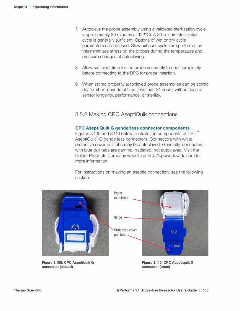
7. Autoclave the probe assembly using a validated sterilization cycle (approximately 30 minutes at 122°C). A 30-minute sterilization cycle is generally sufficient. Options of wet or dry cycle parameters can be used. Slow exhaust cycles are preferred, as this minimizes stress on the probes during the temperature and pressure changes of autoclaving.
8. Allow sufficient time for the probe assembly to cool completely before connecting to the BPC for probe insertion.
9. When stored properly, autoclaved probe assemblies can be stored dry for short periods of time (less than 24 hours) without loss of sensor longevity, performance, or sterility.
3.5.2 Making CPC AseptiQuik connections
CPC AseptiQuik G genderless connector componentsFigures 3.109 and 3.110 below illustrate the components of CPC™ AseptiQuik™ G genderless connectors. Connectors with white protective cover pull tabs may be autoclaved. Generally, connectors with blue pull tabs are gamma irradiated, not autoclaved. Visit the Colder Products Company website at http://cpcworldwide.com for more information.
For instructions on making an aseptic connection, see the following section.
Paper membrane
Protective cover pull tabs
Figure 3.109. CPC Aspetiquik G connector (closed)
Figure 3.110. CPC Aspetiquik G connector (open)
Hinge
Chapter 3 | Operating information
Thermo Scientific HyPerforma 5.1 Single‑Use Bioreactor User's Guide | 108

CPC AseptiQuik connection instructionsThe following steps outline the process of making a sterile aseptic connection using CPC AseptiQuik G genderless connectors.
1. Tear open and remove the plastic covering on the connector located on the BPC (Figures 3.111 and 3.112).
Figure 3.111. Pulling the tear strip
Figure 3.112. Removing plastic covering from connector
Chapter 3 | Operating information
Thermo Scientific HyPerforma 5.1 Single‑Use Bioreactor User's Guide | 109
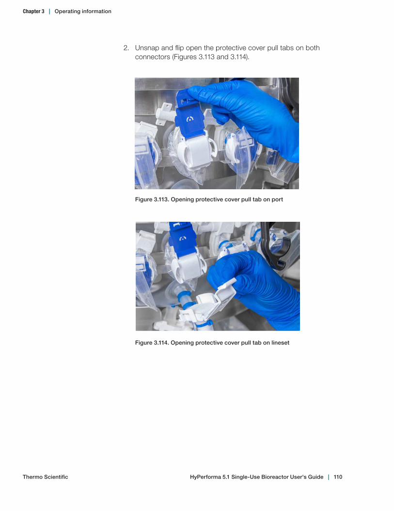
2. Unsnap and flip open the protective cover pull tabs on both connectors (Figures 3.113 and 3.114).
Figure 3.113. Opening protective cover pull tab on port
Figure 3.114. Opening protective cover pull tab on lineset
Chapter 3 | Operating information
Thermo Scientific HyPerforma 5.1 Single‑Use Bioreactor User's Guide | 110
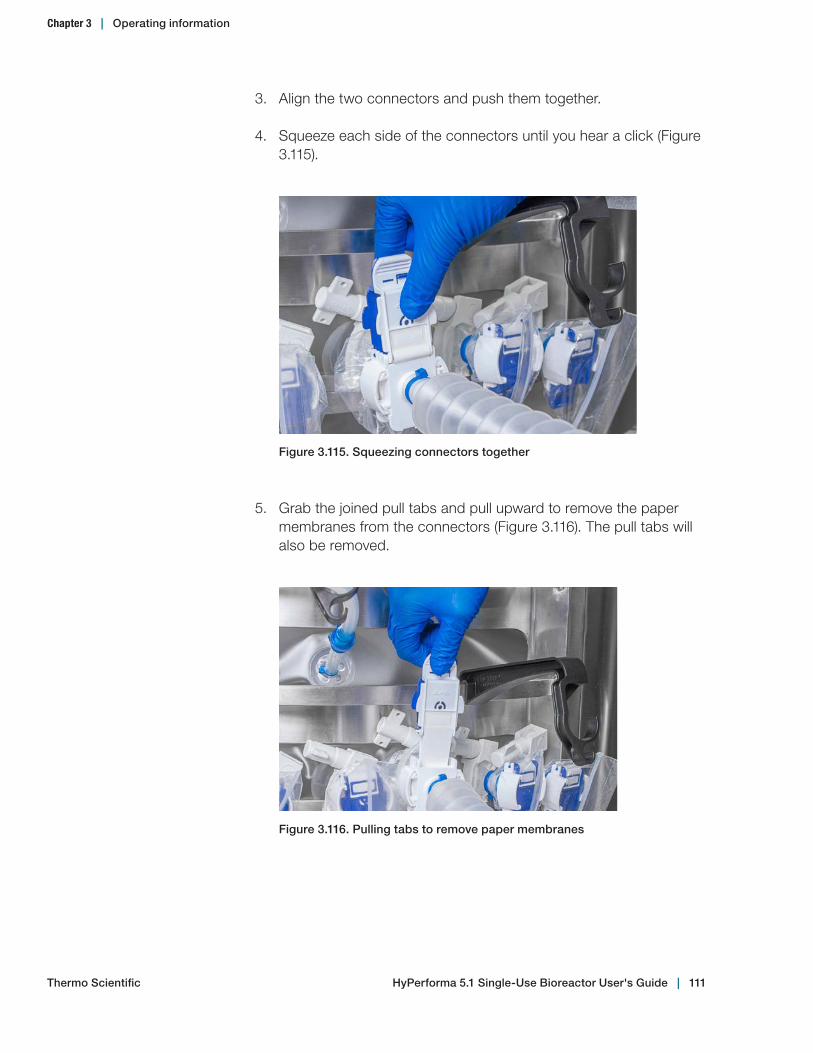
Figure 3.115. Squeezing connectors together
3. Align the two connectors and push them together.
4. Squeeze each side of the connectors until you hear a click (Figure 3.115).
5. Grab the joined pull tabs and pull upward to remove the paper membranes from the connectors (Figure 3.116). The pull tabs will also be removed.
Figure 3.116. Pulling tabs to remove paper membranes
Chapter 3 | Operating information
Thermo Scientific HyPerforma 5.1 Single‑Use Bioreactor User's Guide | 111

3.5.3 Probe insertion
Before beginning probe insertion, please become familiar with the aseptic connector procedure outlined in section 3.5.2.
1. Attach probe clips onto the outer support container above the probe assembly (Figure 3.117). Plastic probe clips slide on with firm pressure.
Figure 3.117. Attaching plastic probe clip
2. Install the pre-sterilized sensor and probe kit using the aseptic connection methods described in section 3.5.2. The aseptic connection is completed prior to the bellows being collapsed.
3. Insert the probe by collapsing the bellows (Figures 3.118 and 3.119). Note: If the BPC is already filled with liquid, the best practice is to squeeze the bellows to expel air prior to collapsing it. Then insert the probe fully, as described.
Figure 3.118. Probe insertion
Chapter 3 | Operating information
Thermo Scientific HyPerforma 5.1 Single‑Use Bioreactor User's Guide | 112

5. Rest the probe in the bellows hook. Release the probe assembly and verify that the probe remains at the proper insertion depth and angle when the bellows expand to rest freely in the probe clip.
Figure 3.120. Positioning probe clip
Bellows hook
Figure 3.119. Collapsed bellows
4. Position the probe clip in the desired horizontal location. Lift the probe and set it into the probe clip (Figure 3.120).
Chapter 3 | Operating information
Thermo Scientific HyPerforma 5.1 Single‑Use Bioreactor User's Guide | 113

3.5.4 Probe calibration
Probe calibration is controller-specific; however, the following general rules apply:• If you are using a liquid batch-to-tank grounding cable with the
stainless steel connector of the sample line, the sample line should be purged of air prior to probe calibration.
• pH probes must be calibrated prior to steam sterilization; the calibration of the probe can be standardized by comparison of an off-line sample once the pH probe has been connected to the S.U.B.
• Dissolved oxygen probes are generally calibrated after steam sterilization. They can be calibrated once the probe is connected to the S.U.B. and is given time to polarize (six to eight hours of continuous connection to the power supply provided by a controller or polarization module).
3.6 Cell culture operating instructions
3.6.1 Operating conditions for cell culture applications
Optimal operating parameters for cell culture vary greatly between cell lines and media formulations. Table 3.7 in section 3.6.8 is provided as a reference for establishing safe upper operating control limits with the standard BPC design. Exceeding these operating limits may result in premature exhaust filter failure, excessive foaming, and excessive pressure build-up in the gas delivery line sets or the BPC.
In many cell culture operations, the limits listed in Table 3.7 are excessive and should be further reduced when possible. When reducing gas flow rate limits, the following trade-offs should be expected.• Reducing drilled hole sparger maximum operating limits will
reduce system foaming but increase reliance on O2. A suggested gas operating control strategy is to run the drilled hole sparger on air initially, and after total flow rate limits are reached, subsitute oxygen as shown in Graph 3.5.
• Reducing overlay maximum operating limits will reduce the exhaust load (increasing filter lifespan) but will sacrifice sparger performance if reduced far enough to allow CO2 buildup in the headspace.
If cell culture density is not increasing at expected rates, this may be due to CO2 buildup in the headspace. Increasing air flow in the headspace may resolve this problem.
Chapter 3 | Operating information
Thermo Scientific HyPerforma 5.1 Single‑Use Bioreactor User's Guide | 114

3.6.2 Checkpoints prior to media fill
Verify the following before proceeding to liquid fill. 9 The BPC has been loaded into the hardware by following the
instructions provided in sections 3.2, 3.3, or 3.4. 9 All aseptic connector port heavy-duty clamps are closed and
located as close as possible to the BPC. 9 The exhaust filter is upright and secured using the holder. 9 The clamp on the drain tube is closed and located as close as
possible to the BPC. 9 The temperature RTD is completely seated in the thermowell and
secured. 9 The air-filled BPC is properly oriented in the outer support
container and the BPC bottom tabs are secured. 9 The gas line sets are connected to the drilled hole sparger and
either the cross flow sparger (for 5:1 operation) or overlay sparger (for 2:1 operation).
9 All gas filters are placed above the maximum liquid level. 9 The load cell display has been tared. 9 The motor is in the "down" position (1,000 L and 2,000 L systems
only) 9 All sensors are inserted and connected to their respective
transmitters. Sensors must be properly oriented to ensure that they are below the liquid level after media fill.
3.6.3 Media fill
1. Select the desired line set from the BPC for fluid introduction.
2. Make an aseptic connection (tubing welder, quick-connect, or tri-clamp) and begin liquid fill.
3. After no more than 20 liters have been added, verify the position of the BPC in the outer support container, particularly the sparger and the drain line. Adjust positioning if necessary for proper fit.
4. Pull the top corners of the BPC upward to reduce wrinkles during filling. Note: If the BPC wrinkles are not eliminated during liquid fill, excessive film tension below the bearing port will result.
5. Fill to the desired liquid volume (20–100% of the rated volume is recommended).
6. Ensure that all sensors are below the liquid level after the BPC has been filled.
Chapter 3 | Operating information
Thermo Scientific HyPerforma 5.1 Single‑Use Bioreactor User's Guide | 115
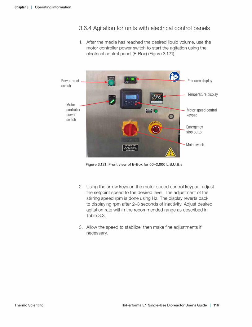
3.6.4 Agitation for units with electrical control panels
1. After the media has reached the desired liquid volume, use the motor controller power switch to start the agitation using the electrical control panel (E-Box) (Figure 3.121).
Power reset switch
Motor controller power switch
Motor speed control keypad
Main switch
Emergency stop button
Pressure display
Figure 3.121. Front view of E‑Box for 50–2,000 L S.U.B.s
Temperature display
2. Using the arrow keys on the motor speed control keypad, adjust the setpoint speed to the desired level. The adjustment of the stirring speed rpm is done using Hz. The display reverts back to displaying rpm after 2–3 seconds of inactivity. Adjust desired agitation rate within the recommended range as described in Table 3.3.
3. Allow the speed to stabilize, then make fine adjustments if necessary.
Chapter 3 | Operating information
Thermo Scientific HyPerforma 5.1 Single‑Use Bioreactor User's Guide | 116

WARNING: Agitation must be stopped when the liquid level falls below 20% of the rated working volume, otherwise damage to the hardware or BPC may result. Do not exceed a 20 W/m3 power ratio when operating between 20% and 50% working volume. See the Warnings, Safety, and Warranty Information section in the front of this publication, and section 3.6.5 for more information about using safety interlocks and agitation speed governors on the controller.
Table 3.3 Recommended agitation rates. The values given are based on a standard scale-up criteria of power input to working volume (P/V) using an estimated power impeller number of 2.1, not the parameters of the motor. For rated maximum and minimum operating speeds for the motor, see the hardware specifications in Chapter 4 of this user's guide. For information on calculating agitation rates using power input to volume ratios, see section 3.6.5—Agitation Rate Calculations.
Power ratio
10 Watts per meters3
(rates in rpm)
Nominal agitation20 Watts per meters3
(rates in rpm)
40 Watts per meters3
(rates in rpm)
Impeller diameter
(cm)
20%
w
orki
ng
volu
me
50%
w
orki
ng
volu
me
100%
w
orki
ng
volu
me
20%
w
orki
ng
volu
me
50%
w
orki
ng
volu
me
100%
w
orki
ng
volu
me
20%
w
orki
ng
volu
me
50%
w
orki
ng
volu
me
100%
w
orki
ng
volu
me
50 L 85 115 145 107 145 183 N/A 183 230* 11.1
100 L 68 92 116 85 116 146 N/A 146 184 14.6
250 L 54 74 93 69 93 117 N/A 117 148 20.0
500 L 47 64 80 59 80 101 N/A 101 127 25.1
1,000 L 39 53 67 50 68 86 N/A 86 109 32.1
2,000 L 35 47 59 44 60 75 N/A ** ** 39.8
* This value is outside the recommended operating motor range of 30–200 rpm (VFD settings). See Table 4.1 in Chapter 4.** Consultation with Thermo Scientific engineers is required.
Chapter 3 | Operating information
Thermo Scientific HyPerforma 5.1 Single‑Use Bioreactor User's Guide | 117
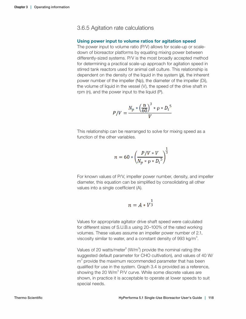
3.6.5 Agitation rate calculations
Using power input to volume ratios for agitation speedThe power input to volume ratio (P/V) allows for scale-up or scale-down of bioreactor platforms by equating mixing power between differently-sized systems. P/V is the most broadly accepted method for determining a practical scale-up approach for agitation speed in stirred tank reactors used for animal cell culture. This relationship is dependent on the density of the liquid in the system (ρ), the inherent power number of the impeller (Np), the diameter of the impeller (Di), the volume of liquid in the vessel (V), the speed of the drive shaft in rpm (n), and the power input to the liquid (P).
This relationship can be rearranged to solve for mixing speed as a function of the other variables.
For known values of P/V, impeller power number, density, and impeller diameter, this equation can be simplified by consolidating all other values into a single coefficient (A).
Values for appropriate agitator drive shaft speed were calculated for different sizes of S.U.B.s using 20–100% of the rated working volumes. These values assume an impeller power number of 2.1, viscosity similar to water, and a constant density of 993 kg/m3.
Values of 20 watts/meter3 (W/m3) provide the nominal rating (the suggested default parameter for CHO cultivation), and values of 40 W/m3 provide the maximum recommended parameter that has been qualified for use in the system. Graph 3.4 is provided as a reference, showing the 20 W/m3 P/V curve. While some discrete values are shown, in practice it is acceptable to operate at lower speeds to suit special needs.
Thermo Scientific
Chapter 3 | Operating information
HyPerforma 5.1 Single‑Use Bioreactor User's Guide | 118
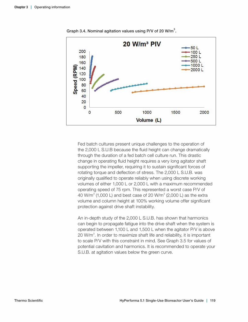
Graph 3.4. Nominal agitation values using P/V of 20 W/m3.
Fed batch cultures present unique challenges to the operation of the 2,000 L S.U.B because the fluid height can change dramatically through the duration of a fed batch cell culture run. This drastic change in operating fluid height requires a very long agitator shaft supporting the impeller, requiring it to sustain significant forces of rotating torque and deflection of stress. The 2,000 L S.U.B. was originally qualified to operate reliably when using discrete working volumes of either 1,000 L or 2,000 L with a maximum recommended operating speed of 75 rpm. This represented a worst case P/V of 40 W/m3 (1,000 L) and best case of 20 W/m3 (2,000 L) as the extra volume and column height at 100% working volume offer significant protection against drive shaft instability.
An in-depth study of the 2,000 L S.U.B. has shown that harmonics can begin to propagate fatigue into the drive shaft when the system is operated between 1,100 L and 1,500 L when the agitator P/V is above 20 W/m3. In order to maximize shaft life and reliability, it is important to scale P/V with this constraint in mind. See Graph 3.5 for values of potential cavitation and harmonics. It is recommended to operate your S.U.B. at agitation values below the green curve.
HyPerforma 5.1 Single‑Use Bioreactor User's Guide | 119Thermo Scientific
Chapter 3 | Operating information
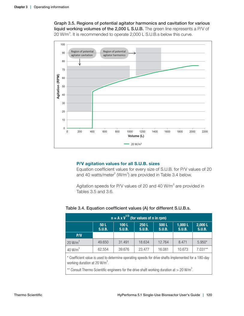
P/V agitation values for all S.U.B. sizesEquation coefficient values for every size of S.U.B. for P/V values of 20 and 40 watts/meter3 (W/m3) are provided in Table 3.4 below.
Agitation speeds for P/V values of 20 and 40 W/m3 are provided in Tables 3.5 and 3.6.
0
10
20
30
40
50
60
70
80
90
100
0 200 400 600 800 1000 1200 1400 1600 1800 2000 2200
Agi
tatio
n (R
PM
)
Volume (L)
2,000 L S.U.B. Agitation Guidelines
20W/m^3
Region of potential agitator cavitation
20 W/m3
Region of potential agitator harmonics
Graph 3.5. Regions of potential agitator harmonics and cavitation for various liquid working volumes of the 2,000 L S.U.B. The green line represents a P/V of 20 W/m3. It is recommended to operate 2,000 L S.U.B.s below this curve.
Table 3.4. Equation coefficient values (A) for different S.U.B.s.
n = A x V1/3 (for values of n in rpm)
50 LS.U.B.
100 LS.U.B.
250 LS.U.B.
500 LS.U.B.
1,000 L S.U.B.
2,000 LS.U.B.
P/V
20 W/m3 49.650 31.491 18.634 12.764 8.471 5.950*
40 W/m3 62.554 39.676 23.477 16.081 10.673 7.031**
* Coefficient value is used to determine operating speeds for drive shafts implemented for a 180-day working duration at 20 W/m3.
** Consult Thermo Scientific engineers for the drive shaft working duration at > 20 W/m3.
Thermo Scientific
Chapter 3 | Operating information
HyPerforma 5.1 Single‑Use Bioreactor User's Guide | 120

Table 3.5. Agitation rates (in rpm) for S.U.B.s at a P/V of 20 W/m3.
50 LS.U.B.
100 LS.U.B.
250 LS.U.B.
500 LS.U.B.
1,000 L S.U.B.
2,000 LS.U.B.*
Fill %
100 183 146 117 101 86 75
95 180 144 115 100 83 74
90 177 141 113 98 82 72
85 173 138 111 96 80 71
80 170 136 109 94 79 70
75 166 133 107 92 77 68
70 162 130 104 90 75 67
65 158 127 102 88 73 65
60 154 123 99 85 71 63
55 150 120 96 83 69 61
50 145 116 93 80 68 60
45 140 112 90 78 65 57
40 135 108 86 75 62 55
35 129 103 83 71 60 53
30 122 98 79 68 57 50
25 115 92 74 64 53 47
20** 107 85 69 59 50 44
* Using these rpm values requires replacement of the drive shaft after 180 days of use.
** These rpm values assume the system is operating at no less than 20% volume. In order to ensure proper volume measurements, end users are responsible for ensuring proper load cell calibration prior to system use.
Chapter 3 | Operating information
Thermo Scientific HyPerforma 5.1 Single‑Use Bioreactor User's Guide | 121
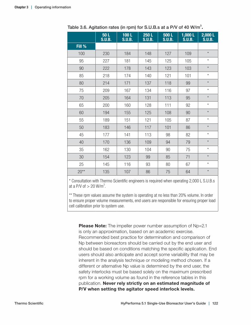
Please Note: The impeller power number assumption of Np=2.1 is only an approximation, based on an academic exercise. Recommended best practice for determination and comparison of Np between bioreactors should be carried out by the end user and should be based on conditions matching the specific application. End users should also anticipate and accept some variability that may be inherent in the analysis technique or modeling method chosen. If a different or alternative Np value is determined by the end user, the safety interlocks must be based solely on the maximum prescribed rpm for a working volume as found in the reference tables in this publication. Never rely strictly on an estimated magnitude of P/V when setting the agitator speed interlock levels.
Table 3.6. Agitation rates (in rpm) for S.U.B.s at a P/V of 40 W/m3.50 L
S.U.B.100 LS.U.B.
250 LS.U.B.
500 LS.U.B.
1,000 L S.U.B.
2,000 LS.U.B.
Fill %
100 230 184 148 127 109 *
95 227 181 145 125 105 *
90 222 178 143 123 103 *
85 218 174 140 121 101 *
80 214 171 137 118 99 *
75 209 167 134 116 97 *
70 205 164 131 113 95 *
65 200 160 128 111 92 *
60 194 155 125 108 90 *
55 189 151 121 105 87 *
50 183 146 117 101 86 *
45 177 141 113 98 82 *
40 170 136 109 94 79 *
35 162 130 104 90 75 *
30 154 123 99 85 71 *
25 145 116 93 80 67 *
20** 135 107 86 75 64 *
* Consultation with Thermo Scientific engineers is required when operating 2,000 L S.U.B.s at a P/V of > 20 W/m3.
** These rpm values assume the system is operating at no less than 20% volume. In order to ensure proper volume measurements, end users are responsible for ensuring proper load cell calibration prior to system use.
Thermo Scientific
Chapter 3 | Operating information
HyPerforma 5.1 Single‑Use Bioreactor User's Guide | 122

3.6.6 Drive shaft rotation
Verify that the drive shaft is rotating counterclockwise when viewed from the top looking down. The S.U.B. is designed to mix in this direction only.
3.6.7 Temperature control
Temperature setpoints are controlled by the TCU or controller. Refer to the TCU or controller manufacturer’s guidelines for setup and operating instructions.
1. Connect to an external TCU using the large couplings located on the vessel jacket. Ensure the inlet/outlet ports are connected properly; improper installation may result in poor heating/cooling performance.
2. Open the valves after connecting the TCU (Figure 3.122).
Note: The water jacket should be purged of air any time the vessel jacket lines are reconnected. To purge the water jacket, open the bleed valve located near the bottom of the S.U.B. A container may be needed to catch any glycol that is released. Close the valve as soon as glycol begins flowing.
Figure 3.122. Opening valves
3.6.8 Sparging strategy
Sparging strategy and gas supply setupStandard 5.1 BPCs are supplied with drilled hole, overlay, and cross flow spargers. Figure 3.123 illustrates the location of each sparger on a standard 500 L BPC. The cross flow sparger is used to reduce carbon dioxide buildup in the headspace near the liquid surface when the liquid volume is at 20%.
Chapter 3 | Operating information
Thermo Scientific HyPerforma 5.1 Single‑Use Bioreactor User's Guide | 123

Graph 3.6 depicts a dissolved oxygen (DO) management strategy. Refer to Table 3.7 in the following section for gas flow rate recommended maximum values. In developing a gassing strategy for a S.U.B. with a drilled hole sparger configuration, it is optional to have a cross over from nitrogen to air when progressing from negative to positive DO control. Graph 3.6 depicts a minor crossover.
When progressing into higher positive DO control, the drilled hole sparger system is designed to maintain optimal oxygen delivery to carbon dioxide stripping rates. When drilled hole sparger flow rate limits are reached, supplant the sparger air flow with a steadily increasing ratio of oxygen to allow a higher degree of control.
Graph 3.6. Drilled hole sparger DO control strategy for 5.1 S.U.B. systems.
Cross flow sparger
Front face
Drilled hole sparger
Overlay sparger
Back face
Figure 3.123. 500 L BPC spargers
Chapter 3 | Operating information
Thermo Scientific HyPerforma 5.1 Single‑Use Bioreactor User's Guide | 124

Gas flow ratesStandard 5.1 BPCs are supplied with drilled hole, overlay, and cross flow spargers. If foaming or exhaust filter load/lifespan is of primary concern, priority should be placed on tuning the system to operate primarily by adding oxygen through the drilled hole sparger. If carbon dioxide stripping is of primary concern, priority should be placed on running the drilled hole sparger at flow rates sufficient to reduce or eliminate the need for base addition.
Table 3.7 contains a listing of operating parameters for all sizes of S.U.B.s. This data may be used in specifying maximum gas flow rates for mass flow controllers or rotameters when using drilled hole spargers. In optimal conditions, without condensation or fouling, the exhaust filters have a flow capacity of at least 20 and 90 slpm (standard liters per minute) at 0.006 bar (0.1 psi) for the small and large standard equipped filter types. The total flow rate of gas into the system must be less than the sum flow rate capacity of active exhaust filters.
The values listed take into account the number and type of exhaust filters that are standard on each size of S.U.B. (one small filter installed in the 50 L and 100 L, one large filter installed in the 250 L and 500 L, and two large filters installed in the 1,000 L and 2,000 L vessels). These values are not absolute requirements. They are also not intended to be process gas flow settings. The process gas flow settings should be adjusted as discussed below, with starting conditions not exceeding 25% of the listed maximum values to prevent unnecessary reduction of exhaust filter life span and foam generation.
Table 3.7. Range of operating parameters.
50 L 100 L 250 L 500 L 1,000 L 2,000 LTemperature (°C)
2.0 - 40.0 ± 0.1
Operating volume (L)
10-50 20-100 50-250 100-500 200-1000 400-2000
Recommended max. gas flow rates (slpm)
DHS
Cros
s flo
w
Over
lay
DHS
Cros
s flo
w
Over
lay
DHS
Cros
s flo
w
Over
lay
DHS
Cros
s flo
w
Over
lay
DHS
Cros
s flo
w
Over
lay
DHS
Cros
s flo
w
Over
lay
Air 5 5 5 10 9 9 25 13 13 50 25 25 100 40 40 200 60 60
O2 5 - - 10 - - 25 - - 50 - - 100 - - 200 - -
CO2 1 - - 2 - - 2 - - 2 - - 5 - - 5 - -
N2 1 - - 2 - - 5 - - 5 - - 10 - - 10 - -
Total 5 5 5 10 9 9 25 13 13 50 25 25 100 40 40 200 60 60
Exhaust load 20 20 90 90 180 360
Chapter 3 | Operating information
Thermo Scientific HyPerforma 5.1 Single‑Use Bioreactor User's Guide | 125

3.6.9 pH probe calibration
If employing a liquid batch-to-tank grounding cable with the stainless steel connector of the sample line, the sample line should be purged of air prior to probe calibration.
In general, the pH probe calibration (post-autoclave) can be verified by pulling a sample and analyzing the pH on another calibrated pH meter.
3.6.10 DO probe calibrationAfter polarizing for six to eight hours, the DO probe can be calibrated in the S.U.B. using standard protocols. Turn on full air sparging. Do not exceed the maximum gassing rates listed in Table 3.7 in section 3.6.8. Sparge until the DO stabilizes. Use the stabilized value as the 100% DO setpoint for the controller. Set the zero percent DO setpoint by sparging with nitrogen, or by temporarily unplugging the DO probe.
3.6.11 Checkpoints prior to inoculation
Before inoculation, verify that: 9 After the S.U.B. is filled with media to 20% or more volume, BPC
tabs have been disconnected from the S.U.B. hardware. 9 The pH probe is calibrated, autoclaved, and connected via an
aseptic connector port. Perform 1-point offset on your controller as necessary.
9 The DO probe is autoclaved, connected via an aseptic connector port, polarized (six to eight hours), and calibrated.
9 The temperature RTD is completely seated in the thermowell and secured.
9 Ensure that all sensors are below the liquid level. 9 Operating parameters (temperature, agitation, pH, and DO) are at
the desired setpoints. 9 A method for making aseptic tubing connections is available. 9 Air is connected to the cross flow sparger when operating at 20%
volume.
3.6.12 Cell inoculation
Once the S.U.B. is operating at the targeted steady equilibrated state and has achieved the proper temperature, the S.U.B. is ready for inoculation. Connect the inoculum addition line set to the seed culture vessel (equipped with the proper connectors/tubing) and transfer the inoculum into the S.U.B.
Chapter 3 | Operating information
Thermo Scientific HyPerforma 5.1 Single‑Use Bioreactor User's Guide | 126
Typically this is done with the tubing connection process (aseptic luer lock connection or tube welding) and peristaltic pump. Pump the desired volume of seed cells into the S.U.B.
Note: For shear sensitive cultures, cells can be introduced by manipulating the addition port to direct the inoculum down the interior wall of the BPC and into the bulk fluid, reducing the shear on the cells. Custom line sets can be supplied with dip tubes, which shorten the distance between the point of inoculum introduction and the bulk fluid level.
3.6.13 Volume scale up
1. Using a sterile process, connect media to the BPC with the media fill port.
2. Begin pumping media into the BPC at the desired flow rate. Ensure that the vessel temperature does not drop below culture limits.
3. Remove the air line from the cross flow sparger, replace onto the overlay gas port, and clamp the cross flow sparger port as close to the BPC as possible.
4. Increase the volume to the desired level.
3.6.14 In-process checkpoints
Verify the following once or twice daily during the culture run. 9 Rising bubbles are visible through the access window. 9 Process parameters, such as temperature and agitation, are at
setpoint. 9 The BPC is not operating under pressure. 9 The cap is tight on the drive shaft. 9 The temperature sensor/RTD is completely seated and secured. 9 No condensate accumulates in exhaust filter housing.
Accumulated condensate indicates that the use of a filter heater is required.
Noise note: Noise may be emitted from the mixing assembly during operation. This noise may vary in intensity and frequency, but generally has no significant effect on performance or overall durability of the BPC during the intended life of the product.
Chapter 3 | Operating information
Thermo Scientific HyPerforma 5.1 Single‑Use Bioreactor User's Guide | 127
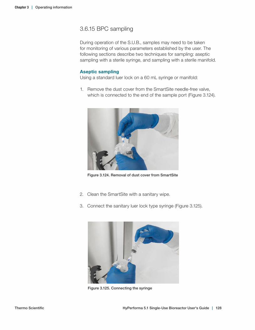
3.6.15 BPC sampling
During operation of the S.U.B., samples may need to be taken for monitoring of various parameters established by the user. The following sections describe two techniques for sampling: aseptic sampling with a sterile syringe, and sampling with a sterile manifold.
Aseptic samplingUsing a standard luer lock on a 60 mL syringe or manifold:
1. Remove the dust cover from the SmartSite needle-free valve, which is connected to the end of the sample port (Figure 3.124).
Figure 3.124. Removal of dust cover from SmartSite
Figure 3.125. Connecting the syringe
2. Clean the SmartSite with a sanitary wipe.
3. Connect the sanitary luer lock type syringe (Figure 3.125).
Chapter 3 | Operating information
Thermo Scientific HyPerforma 5.1 Single‑Use Bioreactor User's Guide | 128
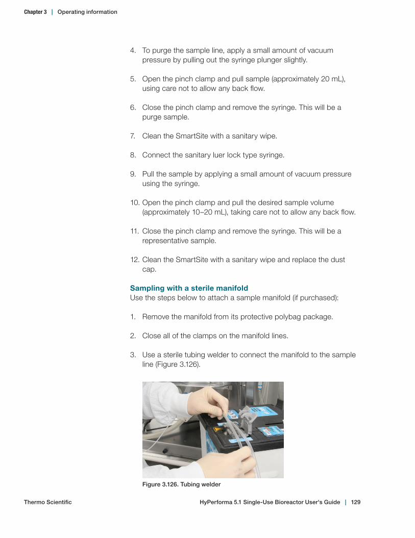
4. To purge the sample line, apply a small amount of vacuum pressure by pulling out the syringe plunger slightly.
5. Open the pinch clamp and pull sample (approximately 20 mL), using care not to allow any back flow.
6. Close the pinch clamp and remove the syringe. This will be a purge sample.
7. Clean the SmartSite with a sanitary wipe.
8. Connect the sanitary luer lock type syringe.
9. Pull the sample by applying a small amount of vacuum pressure using the syringe.
10. Open the pinch clamp and pull the desired sample volume (approximately 10–20 mL), taking care not to allow any back flow.
11. Close the pinch clamp and remove the syringe. This will be a representative sample.
12. Clean the SmartSite with a sanitary wipe and replace the dust cap.
Sampling with a sterile manifoldUse the steps below to attach a sample manifold (if purchased):
1. Remove the manifold from its protective polybag package.
2. Close all of the clamps on the manifold lines.
3. Use a sterile tubing welder to connect the manifold to the sample line (Figure 3.126).
Figure 3.126. Tubing welder
Chapter 3 | Operating information
Thermo Scientific HyPerforma 5.1 Single‑Use Bioreactor User's Guide | 129
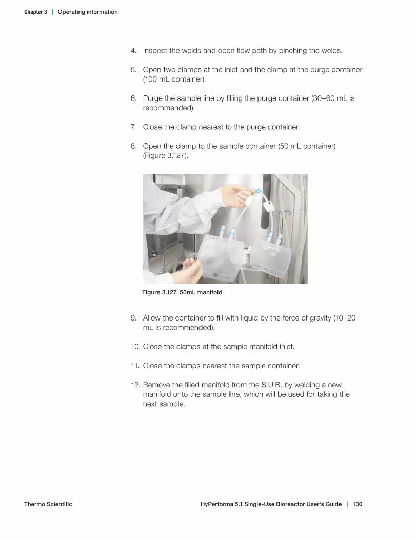
4. Inspect the welds and open flow path by pinching the welds.
5. Open two clamps at the inlet and the clamp at the purge container (100 mL container).
6. Purge the sample line by filling the purge container (30–60 mL is recommended).
7. Close the clamp nearest to the purge container.
8. Open the clamp to the sample container (50 mL container) (Figure 3.127).
Figure 3.127. 50mL manifold
9. Allow the container to fill with liquid by the force of gravity (10–20 mL is recommended).
10. Close the clamps at the sample manifold inlet.
11. Close the clamps nearest the sample container.
12. Remove the filled manifold from the S.U.B. by welding a new manifold onto the sample line, which will be used for taking the next sample.
Chapter 3 | Operating information
Thermo Scientific HyPerforma 5.1 Single‑Use Bioreactor User's Guide | 130
3.6.16 Dispense and harvest
1. Connect the bottom drain tubing set to the intended transfer line.
2. Open the clamp positioned at the bottom drain port.
3. Begin to drain, using a peristaltic pump.
4. Stop the impeller motor when volume reaches 20% maximum volume.
5. Remove and store the drive shaft by reversing the steps used during assembly.
6. Disable the temperature control to ensure that the S.U.B. does not overheat.
7. When approximately three to five liters remain in the BPC, lift the BPC at the top hanging tabs located opposite of the bottom drain (this will pool media toward the drain).
8. Hold the bottom drain line near the floor while lifting the exhaust filter side of the BPC to facilitate draining the final liter of harvest media.
3.6.17 BPC disposal
After the drive shaft has been removed and the BPC has been drained, the BPC can be removed from the outer support container. Filters can be removed and integrity tested as needed according to the user’s standard procedures. All product contact materials related to the S.U.B. can be disposed of in an appropriate waste container or incinerator. Note: For 2,000 L systems, do not lower the BPC lift until the used bag has been removed from the tank.
3.6.18 S.U.B. shutdown
1. After the run is complete, verify that the motor agitation is off and turn off the power to the outer support container by switching off the main power disconnect.
2. If the S.U.B. hardware has come in contact with caustic materials during the course of a run, rinse the affected areas with a light water rinse, followed by normal routine cleaning (see section 3.6.19).
Chapter 3 | Operating information
Thermo Scientific HyPerforma 5.1 Single‑Use Bioreactor User's Guide | 131
3. Loose items such as the drive shaft, tools, and RTD probes should be returned to their storage locations to prevent accidental damage.
3.6.19 Preparation for the next run
Between runs, the S.U.B. hardware (outer support container, probe shelf, drive shaft, mixer drive, etc.) can be wiped down with a sanitary wipe. The outer support container can be cleaned with standard stainless steel cleaner. Store the drive shaft in the storage holder located near the handle of the outer support container.
The S.U.B. hardware system can be cleaned to the extent of standard laboratory cleaning procedures. Care should be taken to ensure electrical connections have been disconnected and electrical enclosures are closed tightly. It is also recommended that excess water is not introduced under the heat shield or over the control panel. A wipe-down with normal disinfectant solutions is sufficient. Avoid using excessive amounts of liquid. The unit must be allowed to fully dry prior to being brought back into operation.
Chapter 3 | Operating information
Thermo Scientific HyPerforma 5.1 Single‑Use Bioreactor User's Guide | 132

3.7 Verification procedures
3.7.1 Mixing speed verification
To verify the mixing speed, use a calibrated tachometer. Expect accuracy of +/- 1.5 rpm or 1% of the setpoint, whichever is greater. Speed scaling can be modified if the calibration needs to be adjusted.
3.7.2 Temperature controller verification
To verify the temperature controller/RTD, use a S.U.B. silicone thermowell, the existing 3.175 mm (1/8 in.) outer diameter (OD) RTD and a user-supplied calibrated temperature bath.
3.7.3 Pressure monitor verification (when present)
To verify the calibration of the pressure monitor, use a calibrated pressure standard. Pressures can be verified by clamping the BPC inlet line and supplying gas through the overlay gas filter. Expect accuracy of +/- 0.1 psi. The monitor can be calibrated manually by referencing the monitor operator’s manual supplied in the Equipment Turnover Package (ETP).
3.7.4 Load cell verification
It is recommended that the load cell manufacturer or a qualified technician verify the load cells onsite. Expect an accuracy of +/- 0.5 kg. Basic load cell default parameters are listed in the electrical schematic included with the ETP.
Chapter 3 | Operating information
Thermo Scientific HyPerforma 5.1 Single‑Use Bioreactor User's Guide | 133

System features and specifications
Chapter contents4.1 Hardware features4.2 Hardware specifications4.3 Electrical control panel features4.4 BPC specifications4.5 Additional system component part numbers
4
Thermo Scientific HyPerforma 5.1 Single‑Use Bioreactor User's Guide | 134
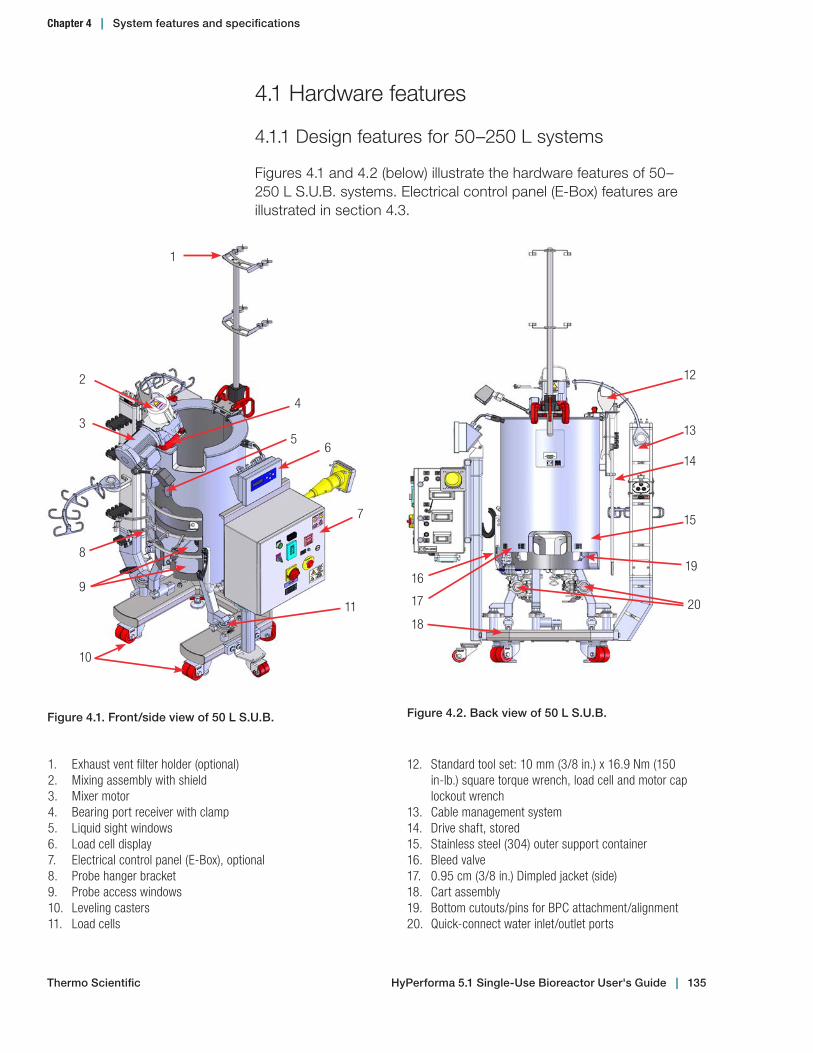
4.1 Hardware features
4.1.1 Design features for 50–250 L systems
Figures 4.1 and 4.2 (below) illustrate the hardware features of 50–250 L S.U.B. systems. Electrical control panel (E-Box) features are illustrated in section 4.3.
1. Exhaust vent filter holder (optional)2. Mixing assembly with shield3. Mixer motor4. Bearing port receiver with clamp5. Liquid sight windows6. Load cell display7. Electrical control panel (E-Box), optional8. Probe hanger bracket9. Probe access windows10. Leveling casters11. Load cells
12. Standard tool set: 10 mm (3/8 in.) x 16.9 Nm (150 in-lb.) square torque wrench, load cell and motor cap lockout wrench
13. Cable management system14. Drive shaft, stored15. Stainless steel (304) outer support container16. Bleed valve17. 0.95 cm (3/8 in.) Dimpled jacket (side)18. Cart assembly19. Bottom cutouts/pins for BPC attachment/alignment20. Quick-connect water inlet/outlet ports
Figure 4.2. Back view of 50 L S.U.B.
12
13
14
15
16
17
18
19
20
1
2
3
4
56
8
9
10
11
Figure 4.1. Front/side view of 50 L S.U.B.
7
Chapter 4 | System features and specifications
Thermo Scientific HyPerforma 5.1 Single‑Use Bioreactor User's Guide | 135
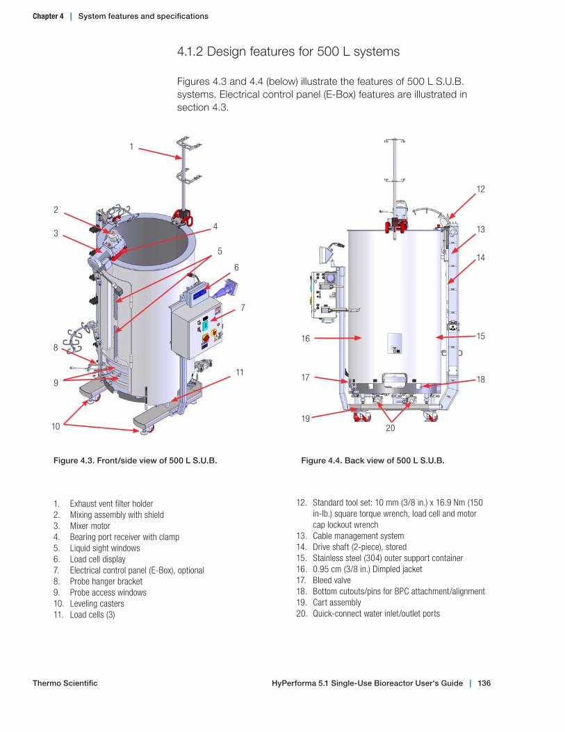
4.1.2 Design features for 500 L systems
Figures 4.3 and 4.4 (below) illustrate the features of 500 L S.U.B. systems. Electrical control panel (E-Box) features are illustrated in section 4.3.
1. Exhaust vent filter holder2. Mixing assembly with shield3. Mixer motor4. Bearing port receiver with clamp5. Liquid sight windows6. Load cell display7. Electrical control panel (E-Box), optional8. Probe hanger bracket9. Probe access windows10. Leveling casters11. Load cells (3)
12. Standard tool set: 10 mm (3/8 in.) x 16.9 Nm (150 in-lb.) square torque wrench, load cell and motor cap lockout wrench
13. Cable management system14. Drive shaft (2-piece), stored15. Stainless steel (304) outer support container16. 0.95 cm (3/8 in.) Dimpled jacket17. Bleed valve18. Bottom cutouts/pins for BPC attachment/alignment19. Cart assembly20. Quick-connect water inlet/outlet ports
Figure 4.3. Front/side view of 500 L S.U.B.
1
2
34
5
6
8
9
10
11
Figure 4.4. Back view of 500 L S.U.B.
14
15
18
16
19
17
13
12
20
7
Thermo Scientific HyPerforma 5.1 Single‑Use Bioreactor User's Guide | 136
Chapter 4 | System features and specifications

4.1.3 Design features for 1,000 L systems
Figures 4.5 and 4.6 (below) illustrate the features of 1,000 L S.U.B. systems. Electrical control panel (E-Box) features are illustrated in section 4.3.
Figure 4.6. Back view of 1,000 L S.U.B.
17
18
19
20
15
14
13
16
1. Mixing assembly with motor safety shield2. Handheld controller (on bracket)3. Drive shaft, stored (3-piece shown)4. BPC loading door and liquid sight windows5. Probe hanger bracket (with probe clips)6. Probe access windows7. Exhaust vent filter holder8. Motor lift9. Mixer motor10. Electrical control panel (E-Box), optional11. Load cell (3)12. Cart assembly
13. 0.95 cm (3/8 in.) Dimpled jacket14. Stainless steel (304) outer support container15. Bleed valve16. Quick-connect water inlet/outlet ports17. Standard tool set: 10 mm (3/8 in.) x 16.9 Nm (150
in-lb.) square torque wrench, load cell and motor cap lockout wrench
18. Cable management system (optional)19. Bottom cutouts/pins for BPC attachment and
alignment20. Leveling casters
Figure 4.5. Front/side view of 1,000 L S.U.B.
1
92
3
4
5
6
7
8
10
12
11
Thermo Scientific HyPerforma 5.1 Single‑Use Bioreactor User's Guide | 137
Chapter 4 | System features and specifications
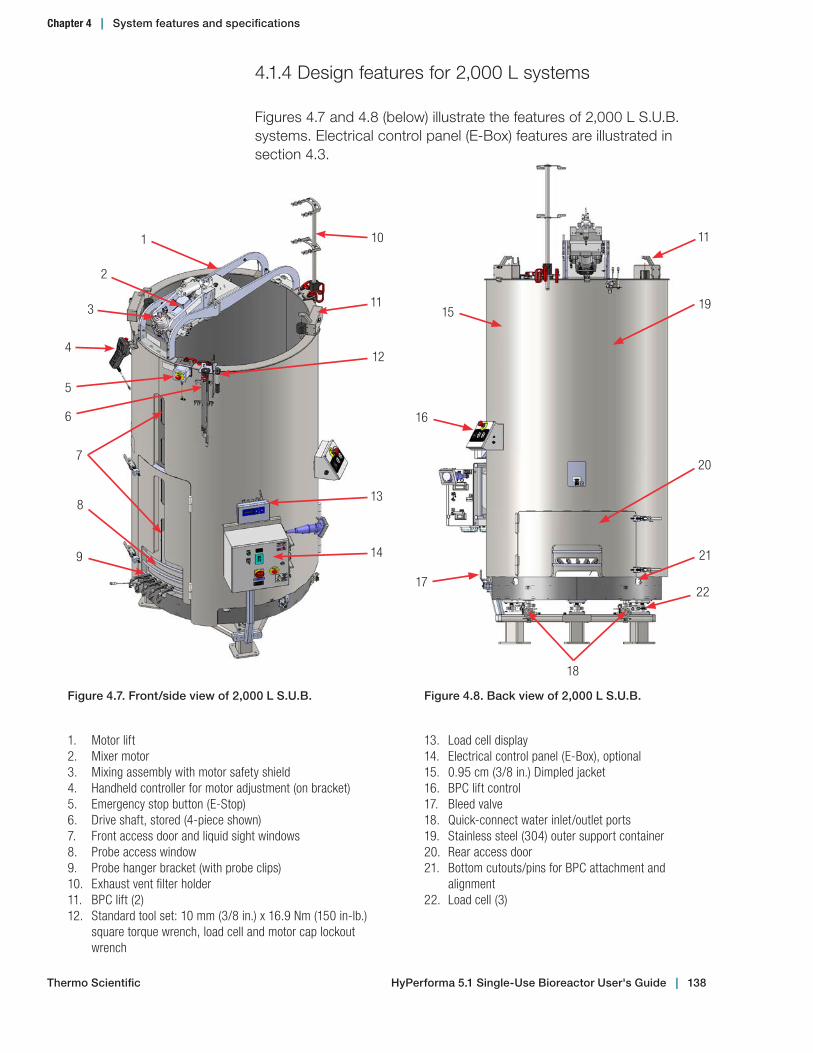
4.1.4 Design features for 2,000 L systems
Figures 4.7 and 4.8 (below) illustrate the features of 2,000 L S.U.B. systems. Electrical control panel (E-Box) features are illustrated in section 4.3.
1. Motor lift2. Mixer motor3. Mixing assembly with motor safety shield4. Handheld controller for motor adjustment (on bracket)5. Emergency stop button (E-Stop)6. Drive shaft, stored (4-piece shown)7. Front access door and liquid sight windows8. Probe access window9. Probe hanger bracket (with probe clips)10. Exhaust vent filter holder11. BPC lift (2)12. Standard tool set: 10 mm (3/8 in.) x 16.9 Nm (150 in-lb.)
square torque wrench, load cell and motor cap lockout wrench
13. Load cell display14. Electrical control panel (E-Box), optional15. 0.95 cm (3/8 in.) Dimpled jacket16. BPC lift control17. Bleed valve18. Quick-connect water inlet/outlet ports19. Stainless steel (304) outer support container20. Rear access door21. Bottom cutouts/pins for BPC attachment and
alignment22. Load cell (3)
Figure 4.8. Back view of 2,000 L S.U.B.
20
21
15
17
19
11
18
16
22
Figure 4.7. Front/side view of 2,000 L S.U.B.
1
2
3 11
5
6
4
7
10
12
6
9
13
14
8
Thermo Scientific HyPerforma 5.1 Single‑Use Bioreactor User's Guide | 138
Chapter 4 | System features and specifications
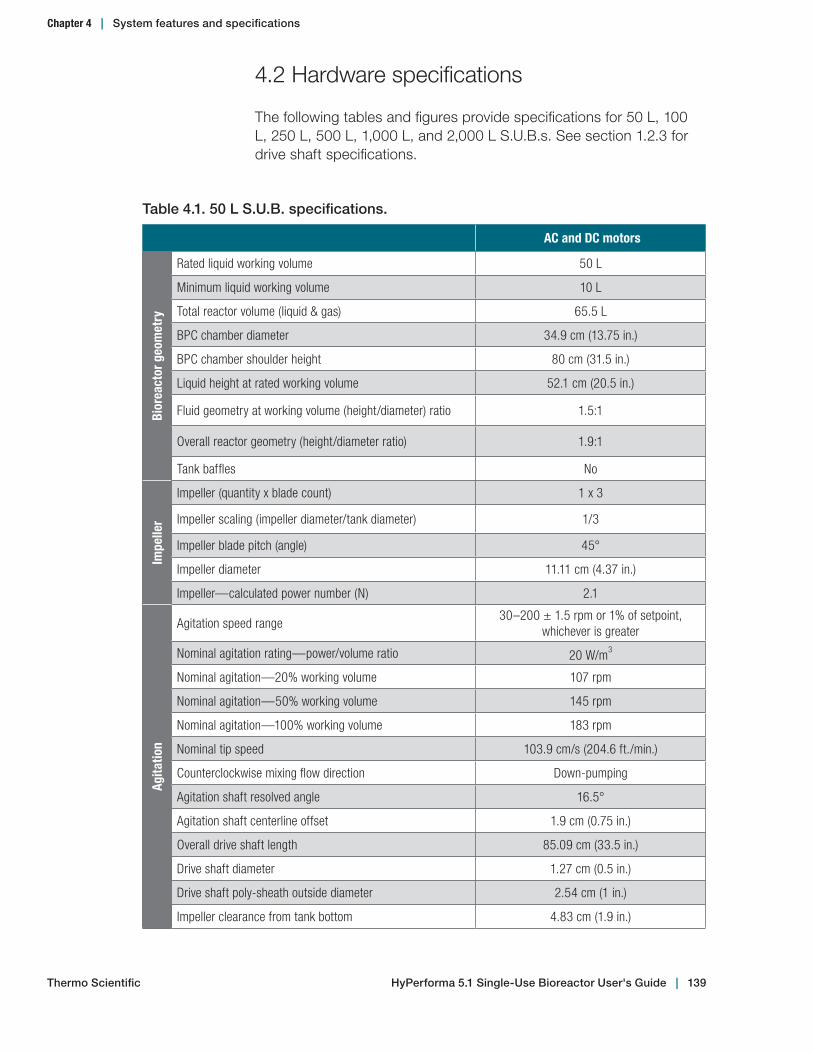
4.2 Hardware specifications
The following tables and figures provide specifications for 50 L, 100 L, 250 L, 500 L, 1,000 L, and 2,000 L S.U.B.s. See section 1.2.3 for drive shaft specifications.
Table 4.1. 50 L S.U.B. specifications.
AC and DC motors
Bior
eact
or g
eom
etry
Rated liquid working volume 50 L
Minimum liquid working volume 10 L
Total reactor volume (liquid & gas) 65.5 L
BPC chamber diameter 34.9 cm (13.75 in.)
BPC chamber shoulder height 80 cm (31.5 in.)
Liquid height at rated working volume 52.1 cm (20.5 in.)
Fluid geometry at working volume (height/diameter) ratio 1.5:1
Overall reactor geometry (height/diameter ratio) 1.9:1
Tank baffles No
Impe
ller
Impeller (quantity x blade count) 1 x 3
Impeller scaling (impeller diameter/tank diameter) 1/3
Impeller blade pitch (angle) 45°
Impeller diameter 11.11 cm (4.37 in.)
Impeller—calculated power number (N) 2.1
Agita
tion
Agitation speed range30–200 ± 1.5 rpm or 1% of setpoint,
whichever is greater
Nominal agitation rating—power/volume ratio 20 W/m3
Nominal agitation—20% working volume 107 rpm
Nominal agitation—50% working volume 145 rpm
Nominal agitation—100% working volume 183 rpm
Nominal tip speed 103.9 cm/s (204.6 ft./min.)
Counterclockwise mixing flow direction Down-pumping
Agitation shaft resolved angle 16.5°
Agitation shaft centerline offset 1.9 cm (0.75 in.)
Overall drive shaft length 85.09 cm (33.5 in.)
Drive shaft diameter 1.27 cm (0.5 in.)
Drive shaft poly-sheath outside diameter 2.54 cm (1 in.)
Impeller clearance from tank bottom 4.83 cm (1.9 in.)
Thermo Scientific HyPerforma 5.1 Single‑Use Bioreactor User's Guide | 139
Chapter 4 | System features and specifications
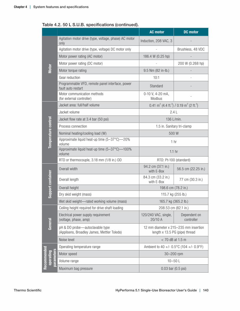
Table 4.2. 50 L S.U.B. specifications (continued).
AC motor DC motor
Mot
or
Agitation motor drive (type, voltage, phase) AC motor only
Induction, 208 VAC, 3 -
Agitation motor drive (type, voltage) DC motor only - Brushless, 48 VDC
Motor power rating (AC motor) 186.4 W (0.25 hp) -
Motor power rating (DC motor) - 200 W (0.268 hp)
Motor torque rating 9.5 Nm (82 in-lb.) -
Gear reduction 10:1 -
Programmable VFD, remote panel interface, power fault auto restart
Standard -
Motor communication methods (for external controller)
0-10 V, 4-20 mA, Modbus
-
Tem
pera
ture
con
trol
Jacket area: full/half volume 0.41 m2 (4.4 ft.2) / 0.19 m2 (2 ft.2)
Jacket volume 2.4 L
Jacket flow rate at 3.4 bar (50 psi) 136 L/min.
Process connection 1.5 in. Sanitary tri-clamp
Nominal heating/cooling load (W) 500 W
Approximate liquid heat-up time (5–37°C)—20% volume
1 hr
Approximate liquid heat-up time (5–37°C)—100% volume
1.1 hr
RTD or thermocouple, 3.18 mm (1/8 in.) OD RTD: Pt-100 (standard)
Supp
ort c
onta
iner
Overall width94.2 cm (37.1 in.)
with E-Box56.5 cm (22.25 in.)
Overall length84.3 cm (33.2 in.)
with E-Box77 cm (30.3 in.)
Overall height 198.6 cm (78.2 in.)
Dry skid weight (mass) 115.7 kg (255 lb.)
Wet skid weight—rated working volume (mass) 165.7 kg (365.2 lb.)
Gene
ral
Ceiling height required for drive shaft loading 208.53 cm (82.1 in.)
Electrical power supply requirement (voltage, phase, amp)
120/240 VAC, single, 20/10 A
Dependent on controller
pH & DO probe—autoclavable type (Applisens, Broadley James, Mettler Toledo)
12 mm diameter x 215–235 mm insertion length x 13.5 PG (pipe) thread
Noise level < 70 dB at 1.5 m
Reco
mm
ende
d op
erat
ing
pa
ram
eter
s
Operating temperature range Ambient to 40 +/- 0.5°C (104 +/- 0.9°F)
Motor speed 30–200 rpm
Volume range 10–50 L
Maximum bag pressure 0.03 bar (0.5 psi)
Thermo Scientific HyPerforma 5.1 Single‑Use Bioreactor User's Guide | 140
Chapter 4 | System features and specifications
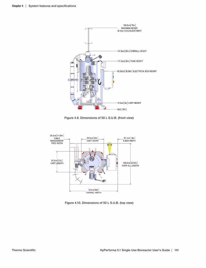
Figure 4.9. Dimensions of 50 L S.U.B. (front view)
Figure 4.10. Dimensions of 50 L S.U.B. (top view)
HyPerforma 5.1 Single‑Use Bioreactor User's Guide | 141Thermo Scientific
Chapter 4 | System features and specifications
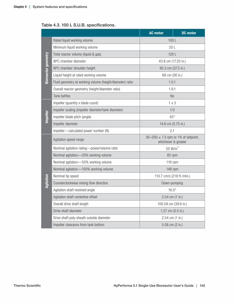
Table 4.3. 100 L S.U.B. specifications.
AC motor DC motor
Bior
eact
or g
eom
etry
Rated liquid working volume 100 L
Minimum liquid working volume 20 L
Total reactor volume (liquid & gas) 120 L
BPC chamber diameter 43.8 cm (17.25 in.)
BPC chamber shoulder height 95.3 cm (37.5 in.)
Liquid height at rated working volume 66 cm (26 in.)
Fluid geometry at working volume (height/diameter) ratio 1.5:1
Overall reactor geometry (height/diameter ratio) 1.9:1
Tank baffles No
Impe
ller
Impeller (quantity x blade count) 1 x 3
Impeller scaling (impeller diameter/tank diameter) 1/3
Impeller blade pitch (angle) 45°
Impeller diameter 14.6 cm (5.75 in.)
Impeller—calculated power number (N) 2.1
Agita
tion
Agitation speed range30–200 ± 1.5 rpm or 1% of setpoint,
whichever is greater
Nominal agitation rating—power/volume ratio 20 W/m3
Nominal agitation—20% working volume 85 rpm
Nominal agitation—50% working volume 116 rpm
Nominal agitation—100% working volume 146 rpm
Nominal tip speed 110.7 cm/s (218 ft./min.)
Counterclockwise mixing flow direction Down-pumping
Agitation shaft resolved angle 16.5°
Agitation shaft centerline offset 2.54 cm (1 in.)
Overall drive shaft length 100.58 cm (39.6 in.)
Drive shaft diameter 1.27 cm (0.5 in.)
Drive shaft poly-sheath outside diameter 2.54 cm (1 in.)
Impeller clearance from tank bottom 5.08 cm (2 in.)
Thermo Scientific HyPerforma 5.1 Single‑Use Bioreactor User's Guide | 142
Chapter 4 | System features and specifications
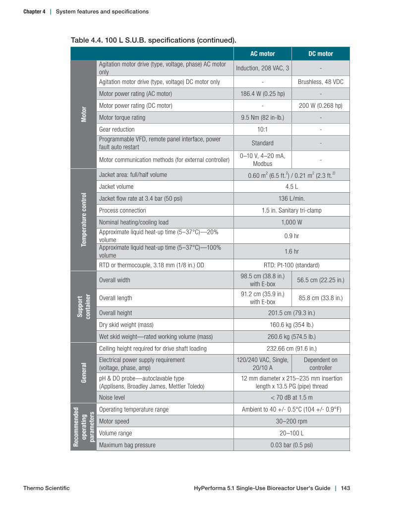
Table 4.4. 100 L S.U.B. specifications (continued).
AC motor DC motor
Mot
or
Agitation motor drive (type, voltage, phase) AC motor only
Induction, 208 VAC, 3 -
Agitation motor drive (type, voltage) DC motor only - Brushless, 48 VDC
Motor power rating (AC motor) 186.4 W (0.25 hp) -
Motor power rating (DC motor) - 200 W (0.268 hp)
Motor torque rating 9.5 Nm (82 in-lb.) -
Gear reduction 10:1 -
Programmable VFD, remote panel interface, power fault auto restart
Standard -
Motor communication methods (for external controller)0–10 V, 4–20 mA,
Modbus-
Tem
pera
ture
con
trol
Jacket area: full/half volume 0.60 m2 (6.5 ft.2) / 0.21 m2 (2.3 ft.2)
Jacket volume 4.5 L
Jacket flow rate at 3.4 bar (50 psi) 136 L/min.
Process connection 1.5 in. Sanitary tri-clamp
Nominal heating/cooling load 1,000 W
Approximate liquid heat-up time (5–37°C)—20% volume
0.9 hr
Approximate liquid heat-up time (5–37°C)—100% volume
1.6 hr
RTD or thermocouple, 3.18 mm (1/8 in.) OD RTD: Pt-100 (standard)
Supp
ort
cont
aine
r
Overall width98.5 cm (38.8 in.)
with E-box56.5 cm (22.25 in.)
Overall length91.2 cm (35.9 in.)
with E-box85.8 cm (33.8 in.)
Overall height 201.5 cm (79.3 in.)
Dry skid weight (mass) 160.6 kg (354 lb.)
Wet skid weight—rated working volume (mass) 260.6 kg (574.5 lb.)
Gene
ral
Ceiling height required for drive shaft loading 232.66 cm (91.6 in.)
Electrical power supply requirement (voltage, phase, amp)
120/240 VAC, Single, 20/10 A
Dependent on controller
pH & DO probe—autoclavable type (Applisens, Broadley James, Mettler Toledo)
12 mm diameter x 215–235 mm insertion length x 13.5 PG (pipe) thread
Noise level < 70 dB at 1.5 m
Reco
mm
ende
d
oper
atin
g
para
met
ers Operating temperature range Ambient to 40 +/- 0.5°C (104 +/- 0.9°F)
Motor speed 30–200 rpm
Volume range 20–100 L
Maximum bag pressure 0.03 bar (0.5 psi)
Thermo Scientific HyPerforma 5.1 Single‑Use Bioreactor User's Guide | 143
Chapter 4 | System features and specifications

Figure 4.11. Dimensions of 100 L S.U.B. (front view)
Figure 4.12. Dimensions of 100 L S.U.B. (top view)
Chapter 4 | System features and specifications
HyPerforma 5.1 Single‑Use Bioreactor User's Guide | 144Thermo Scientific

Table 4.5. 250 L S.U.B. specifications.
AC and DC motors
Bior
eact
or g
eom
etry
Rated liquid working volume 250 L
Minimum liquid working volume 50 L
Total reactor volume (liquid & gas) 316 L
BPC chamber diameter 59.7 cm (23.5 in.)
BPC chamber shoulder height 115.6 cm (45.5 in.)
Liquid height at rated working volume 91.4 cm (36 in.)
Fluid geometry at working volume (height/diameter) ratio 1.5:1
Overall reactor geometry (height/diameter ratio)
1.9:1
Tank baffles No
Impe
ller
Impeller (quantity x blade count) 1 x 3
Impeller scaling (impeller diameter/tank diameter) 1/3
Impeller blade pitch (angle) 45°
Impeller diameter 20 cm (7.875 in.)
Impeller—calculated power number (N) 2.1
Agita
tion
Agitation speed range30–150 ± 1.5 rpm or 1% of setpoint,
whichever is greater
Nominal agitation rating—power/volume ratio 20 W/m3
Nominal agitation—20% working volume 69 rpm
Nominal agitation—50% working volume 93 rpm
Nominal agitation—100% working volume 117 rpm
Nominal tip speed 123.6 cm/s (243.3 ft./min.)
Counterclockwise mixing flow direction Down-pumping
Agitation shaft resolved angle 16.5°
Agitation shaft centerline offset 3.3 cm (1.3 in.)
Overall drive shaft length 120.90 cm (47.6 in.)
Drive shaft diameter 1.27 cm (0.5 in.)
Drive shaft poly-sheath outside diameter 2.54 cm (1 in.)
Impeller clearance from tank bottom 6.91 cm (2.72 in.)
Thermo Scientific HyPerforma 5.1 Single‑Use Bioreactor User's Guide | 145
Chapter 4 | System features and specifications

Table 4.6. 250 L S.U.B. specifications (continued).
AC motor DC motor
Mot
or
Agitation motor drive (type, voltage, phase) AC motor only
Induction, 208 VAC, 3 -
Agitation motor drive (type, voltage) DC motor only - Brushless, 48 VDC
Motor power rating (AC motor) 186.4 W (0.25 hp) -
Motor power rating (DC motor) - 400 W (0.536 hp)
Motor torque rating 11.5 Nm (102 in-lb.) -
Gear reduction 12.5:1 -
Programmable VFD, remote panel interface, power faults auto restart
Standard -
Motor communication methods (for external controller)0–10 V, 4–20 mA,
Modbus-
Tem
pera
ture
con
trol
Jacket area: full/half volume 1.26 m2 (13.6 ft.2) / 0.54 m2 (5.8 ft.2)
Jacket volume 8.6 L
Jacket flow rate at 3.4 bar (50 psi) 136 L/min.
Process connection 1.5 in. Sanitary tri-clamp
Nominal heating/cooling load (W) 2,500 W
Approximate liquid heat-up time (5–37°C)—20% volume
1.1 hr
Approximate liquid heat-up time (5–37°C)—100% volume
3.4 hr
RTD or thermocouple, 3.18 mm (1/8 in.) OD RTD: Pt-100 (standard)
Supp
ort c
onta
iner
Overall width112.8 cm (44.4 in.)
(with E-box)68.5 cm (27 in.)
Overall length102.2 cm (40.25 in.)
(with E-box)96.9 cm (38.15 in.)
Overall height 215.5 cm (84.8 in.)
Dry skid weight (mass) 223.6 kg (493 lb.)
Wet skid weight—rated working volume (mass) 473.6 kg (1044 lb.)
Gene
ral
Ceiling height required for drive shaft loading
267.46 cm (105.3 in.)
Electrical power supply requirement (voltage, phase, amp)
120/240 VAC, single, 20/10 A
Dependent on controller
pH & DO probe–autoclavable type (Applisens, Broadley James, Mettler Toledo)
12 mm diameter x 215–235 mm insertion length x 13.5 PG thread
Noise level < 70 dB at 1.5 m
Reco
mm
ende
d
oper
atin
g
para
met
ers Operating temperature range Ambient to 40 +/- 0.5°C (104 +/- 0.9°F)
Motor speed 30–150 rpm
Volume range 50–250 L
Maximum bag pressure 0.03 bar (0.5 psi)
Thermo Scientific HyPerforma 5.1 Single‑Use Bioreactor User's Guide | 146
Chapter 4 | System features and specifications

Figure 4.13. Dimensions of 250 L S.U.B. (front view)
Figure 4.14. Dimensions of 250 L S.U.B. (top view)
Chapter 4 | System features and specifications
HyPerforma 5.1 Single‑Use Bioreactor User's Guide | 147Thermo Scientific
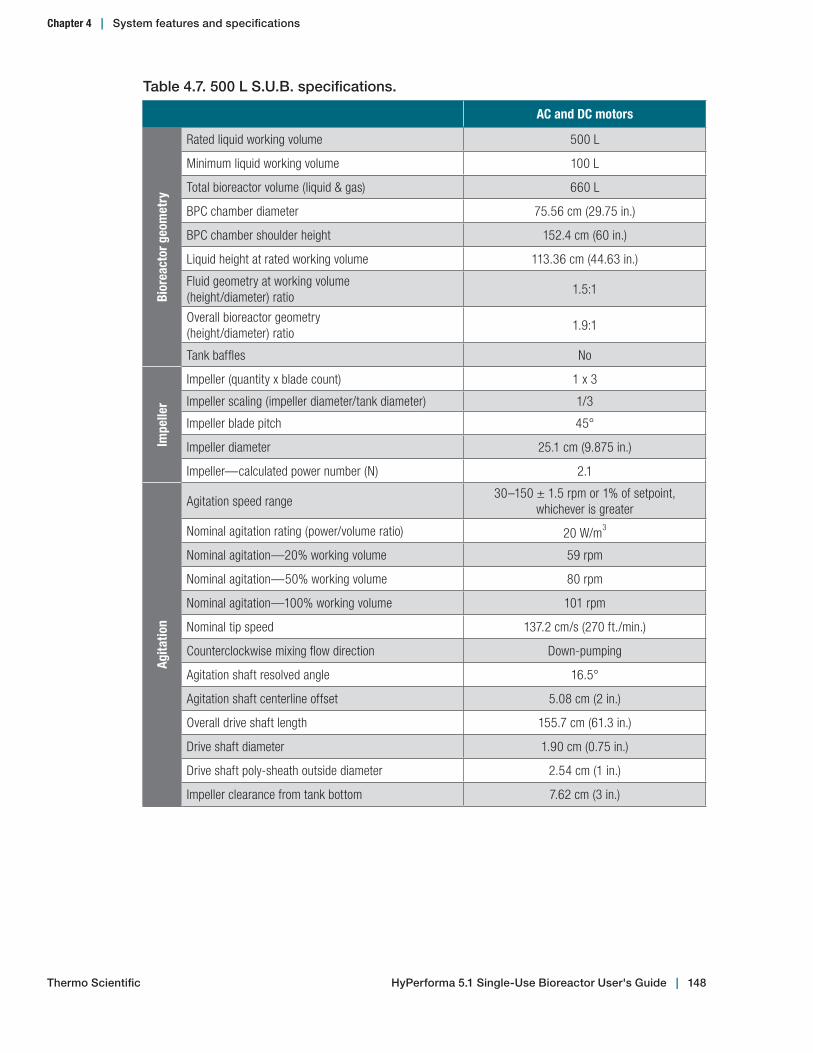
Table 4.7. 500 L S.U.B. specifications.
AC and DC motors
Bior
eact
or g
eom
etry
Rated liquid working volume 500 L
Minimum liquid working volume 100 L
Total bioreactor volume (liquid & gas) 660 L
BPC chamber diameter 75.56 cm (29.75 in.)
BPC chamber shoulder height 152.4 cm (60 in.)
Liquid height at rated working volume 113.36 cm (44.63 in.)
Fluid geometry at working volume (height/diameter) ratio
1.5:1
Overall bioreactor geometry (height/diameter) ratio
1.9:1
Tank baffles No
Impe
ller
Impeller (quantity x blade count) 1 x 3
Impeller scaling (impeller diameter/tank diameter) 1/3
Impeller blade pitch 45°
Impeller diameter 25.1 cm (9.875 in.)
Impeller—calculated power number (N) 2.1
Agita
tion
Agitation speed range30–150 ± 1.5 rpm or 1% of setpoint,
whichever is greater
Nominal agitation rating (power/volume ratio) 20 W/m3
Nominal agitation—20% working volume 59 rpm
Nominal agitation—50% working volume 80 rpm
Nominal agitation—100% working volume 101 rpm
Nominal tip speed 137.2 cm/s (270 ft./min.)
Counterclockwise mixing flow direction Down-pumping
Agitation shaft resolved angle 16.5°
Agitation shaft centerline offset 5.08 cm (2 in.)
Overall drive shaft length 155.7 cm (61.3 in.)
Drive shaft diameter 1.90 cm (0.75 in.)
Drive shaft poly-sheath outside diameter 2.54 cm (1 in.)
Impeller clearance from tank bottom 7.62 cm (3 in.)
Thermo Scientific HyPerforma 5.1 Single‑Use Bioreactor User's Guide | 148
Chapter 4 | System features and specifications
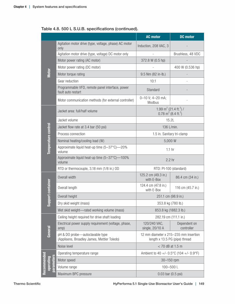
Table 4.8. 500 L S.U.B. specifications (continued).
AC motor DC motor
Mot
orAgitation motor drive (type, voltage, phase) AC motor only
Induction, 208 VAC, 3 -
Agitation motor drive (type, voltage) DC motor only - Brushless, 48 VDC
Motor power rating (AC motor) 372.8 W (0.5 hp) -
Motor power rating (DC motor) - 400 W (0.536 hp)
Motor torque rating 9.5 Nm (82 in-lb.) -
Gear reduction 10:1 -
Programmable VFD, remote panel interface, power fault auto restart
Standard -
Motor communication methods (for external controller)0–10 V; 4–20 mA;
Modbus-
Tem
pera
ture
con
trol
Jacket area: full/half volume 1.99 m2 (21.4 ft.2) / 0.78 m2 (8.4 ft.2)
Jacket volume 15.2L
Jacket flow rate at 3.4 bar (50 psi) 136 L/min.
Process connection 1.5 in. Sanitary tri-clamp
Nominal heating/cooling load (W) 5,000 W
Approximate liquid heat-up time (5–37°C)—20% volume
1.1 hr
Approximate liquid heat-up time (5–37°C)—100% volume
2.2 hr
RTD or thermocouple, 3.18 mm (1/8 in.) OD RTD: Pt-100 (standard)
Supp
ort c
onta
iner
Overall width125.2 cm (49.3 in.)
with E-Box86.4 cm (34 in.)
Overall length124.4 cm (47.8 in.)
with E-Box116 cm (45.7 in.)
Overall height 251.1 cm (98.9 in.)
Dry skid weight (mass) 353.8 kg (780 lb.)
Wet skid weight—rated working volume (mass) 853.8 kg (1882.3 lb.)
Gene
ral
Ceiling height required for drive shaft loading 282.19 cm (111.1 in.)
Electrical power supply requirement (voltage, phase, amp)
120/240 VAC, single, 20/10 A
Dependent on controller
pH & DO probe—autoclavable type (Applisens, Broadley James, Mettler Toledo)
12 mm diameter x 215–235 mm insertion length x 13.5 PG (pipe) thread
Noise level < 70 dB at 1.5 m
Reco
mm
ende
d op
erat
ing
para
met
ers Operating temperature range Ambient to 40 +/- 0.5°C (104 +/- 0.9°F)
Motor speed 30–150 rpm
Volume range 100–500 L
Maximum BPC pressure 0.03 bar (0.5 psi)
Thermo Scientific HyPerforma 5.1 Single‑Use Bioreactor User's Guide | 149
Chapter 4 | System features and specifications
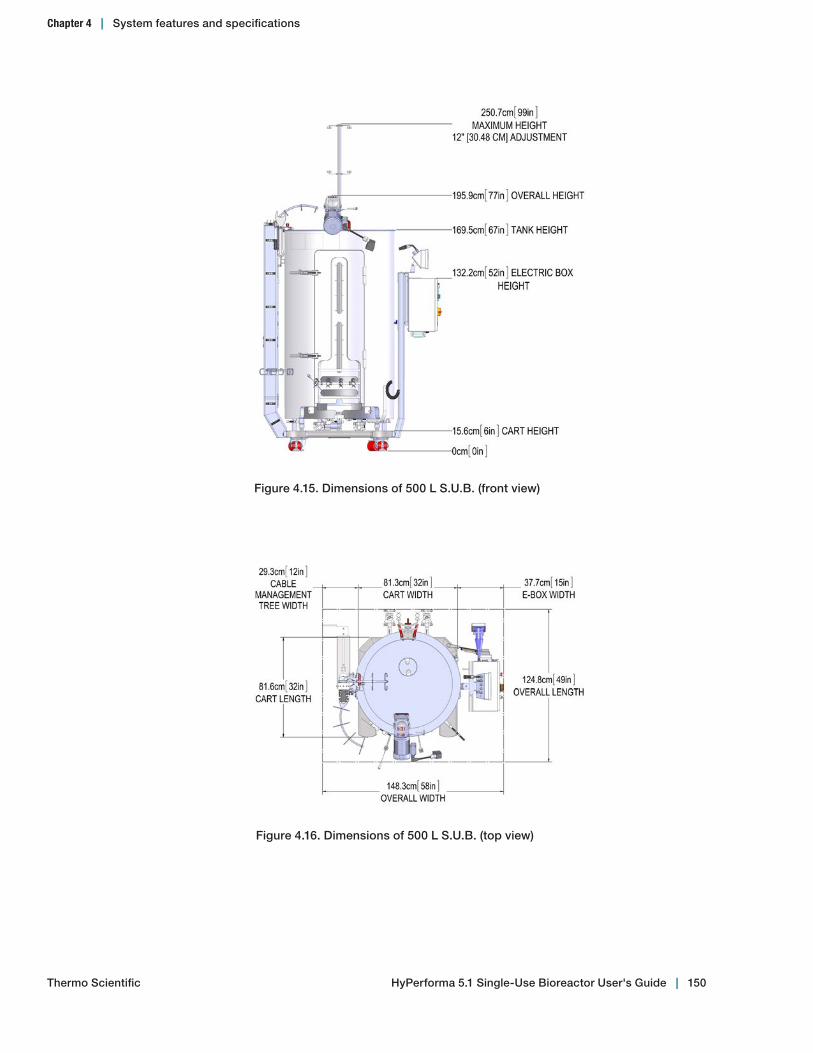
Figure 4.15. Dimensions of 500 L S.U.B. (front view)
Figure 4.16. Dimensions of 500 L S.U.B. (top view)
HyPerforma 5.1 Single‑Use Bioreactor User's Guide | 150Thermo Scientific
Chapter 4 | System features and specifications
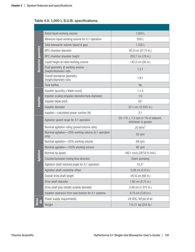
Table 4.9. 1,000 L S.U.B. specifications.
Bior
eact
or g
eom
etry
Rated liquid working volume 1,000 L
Minimum liquid working volume for 5:1 operation 200 L
Total bioreactor volume (liquid & gas) 1,320 L
BPC chamber diameter 95.9 cm (37.75 in.)
BPC chamber shoulder height 200.7 cm (79 in.)
Liquid height at rated working volume 142.2 cm (56 in.)
Fluid geometry at working volume (height/diameter) ratio
1.5:1
Overall bioreactor geometry (height/diameter) ratio
1.9:1
Tank baffles No
Impe
ller
Impeller (quantity x blade count) 1 x 3
Impeller scaling (impeller diameter/tank diameter) 1/3
Impeller blade pitch 45°
Impeller diameter 32.1 cm (12.625 in.)
Impeller—calculated power number (N) 2.1
Agita
tion
Agitation speed range for 5:1 operation20–110 ± 1.5 rpm or 1% of setpoint,
whichever is greater
Nominal agitation rating (power/volume ratio) 20 W/m3
Nominal agitation—20% working volume (5:1 operation only)
50 rpm
Nominal agitation—50% working volume 68 rpm
Nominal agitation—100% working volume 86 rpm
Nominal tip speed 146.1 cm/s (287.6 ft./min.)
Counterclockwise mixing flow direction Down-pumping
Agitation shaft resolved angle for 5:1 operation 15.3°
Agitation shaft centerline offset 5.08 cm (2.0 in.)
Overall drive shaft length 167.6 cm (66 in.)
Drive shaft diameter 1.90 cm (0.75 in.)
Drive shaft poly-sheath outside diameter 3.49 cm (1.375 in.)
Impeller clearance from tank bottom for 5.1 systems 9.73 cm (3.83 in.)
Mot
or
lift Power supply requirements 24 VDC, 90 psi of air
Weight 115.21 kg (254 lb.)
Thermo Scientific HyPerforma 5.1 Single‑Use Bioreactor User's Guide | 151
Chapter 4 | System features and specifications

Table 4.10. 1,000 L S.U.B. specifications (continued).
Mot
or
Agitation motor drive (type, voltage, phase) Induction, 208 AC, 3
Motor power rating 372.8 W (0.5 hp)
Motor torque rating 27.7 Nm (245 in-lb.)
Gear reduction 15:1
Programmable VFD, remote panel interface, power fault auto restart
Standard
Motor communication methods (for external controller) 0–10 V; 4–20 mA; Modbus
Tem
pera
ture
con
trol
Jacket area: full/half volume 3.31 m2 (35.6 ft.2) /1.38 m2 (14.9 ft.2)
Jacket volume 23.5 L
Jacket flow rate at 3.4 bar (50 psi) 136 L/min.
Process connection 1.5 in. Sanitary tri-clamp
Nominal heating/cooling load (W) 9,000 W
Approximate liquid heat-up time (5–37°C)—20% volume
1.2 hr
Approximate liquid heat-up time (5–37°C)—100% volume
4.1 hr
RTD or thermocouple, 3.18 mm (1/8 in.) OD RTD: Pt-100 (standard)
Supp
ort c
onta
iner Overall width 143.8 cm (56.6 in.) with E-Box
Overall length 139.2 cm (54.8 in.) with E-Box
Overall height 284 cm (111.8 in.)
Dry skid weight (mass) 655.01 kg (1,444 lb.)
Wet skid weight—rated working volume (mass) 1,655.01 kg (3,649 lb.)
Gene
ral
Ceiling height required for drive shaft loading 287 cm (113 in.)
Electrical power supply requirement (voltage, phase, amp)
208–240 VAC, single, 30 A/dependent on controller
pH & DO probe—autoclavable type (Applisens, Broadley James, Mettler Toledo)
12 mm diameter x 215–235 mm insertion length x 13.5 PG (pipe) thread
Noise level < 70 dB at 1.5 m
Reco
mm
ende
d op
erat
ing
para
met
ers Operating temperature range Ambient to 40 +/- 0.5°C (104 +/- 0.9°F)
Motor speed 20–110 rpm
Volume range 200–1,000 L
Maximum BPC pressure 0.03 bar (0.5 psi)
Thermo Scientific HyPerforma 5.1 Single‑Use Bioreactor User's Guide | 152
Chapter 4 | System features and specifications

Figure 4.17. Dimensions of 1,000 L S.U.B. (front view)
Figure 4.18. Dimensions of 1,000 L S.U.B. (top view)
Chapter 4 | System features and specifications
HyPerforma 5.1 Single‑Use Bioreactor User's Guide | 153Thermo Scientific
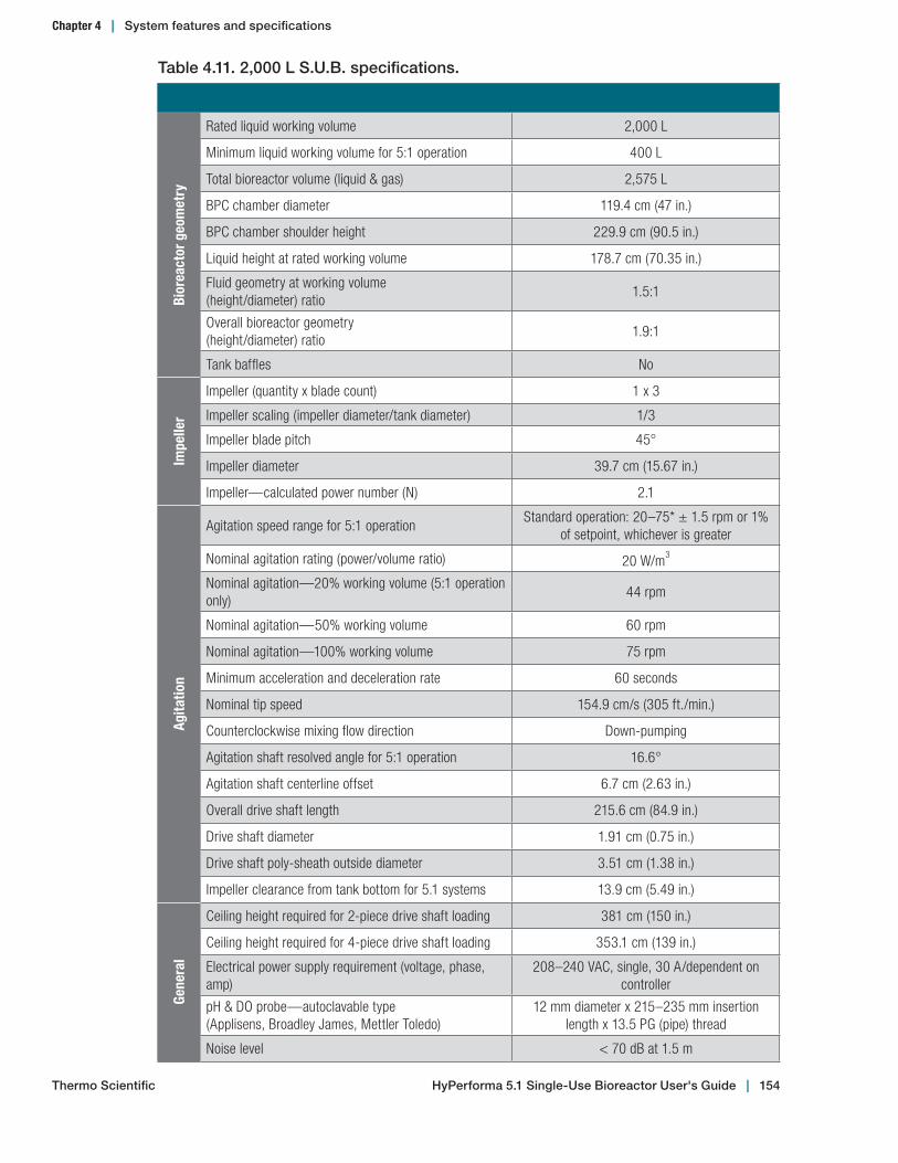
Table 4.11. 2,000 L S.U.B. specifications.
Bior
eact
or g
eom
etry
Rated liquid working volume 2,000 L
Minimum liquid working volume for 5:1 operation 400 L
Total bioreactor volume (liquid & gas) 2,575 L
BPC chamber diameter 119.4 cm (47 in.)
BPC chamber shoulder height 229.9 cm (90.5 in.)
Liquid height at rated working volume 178.7 cm (70.35 in.)
Fluid geometry at working volume (height/diameter) ratio
1.5:1
Overall bioreactor geometry (height/diameter) ratio
1.9:1
Tank baffles No
Impe
ller
Impeller (quantity x blade count) 1 x 3
Impeller scaling (impeller diameter/tank diameter) 1/3
Impeller blade pitch 45°
Impeller diameter 39.7 cm (15.67 in.)
Impeller—calculated power number (N) 2.1
Agita
tion
Agitation speed range for 5:1 operationStandard operation: 20–75* ± 1.5 rpm or 1%
of setpoint, whichever is greater
Nominal agitation rating (power/volume ratio) 20 W/m3
Nominal agitation—20% working volume (5:1 operation only)
44 rpm
Nominal agitation—50% working volume 60 rpm
Nominal agitation—100% working volume 75 rpm
Minimum acceleration and deceleration rate 60 seconds
Nominal tip speed 154.9 cm/s (305 ft./min.)
Counterclockwise mixing flow direction Down-pumping
Agitation shaft resolved angle for 5:1 operation 16.6°
Agitation shaft centerline offset 6.7 cm (2.63 in.)
Overall drive shaft length 215.6 cm (84.9 in.)
Drive shaft diameter 1.91 cm (0.75 in.)
Drive shaft poly-sheath outside diameter 3.51 cm (1.38 in.)
Impeller clearance from tank bottom for 5.1 systems 13.9 cm (5.49 in.)
Gene
ral
Ceiling height required for 2-piece drive shaft loading 381 cm (150 in.)
Ceiling height required for 4-piece drive shaft loading 353.1 cm (139 in.)
Electrical power supply requirement (voltage, phase, amp)
208–240 VAC, single, 30 A/dependent on controller
pH & DO probe—autoclavable type (Applisens, Broadley James, Mettler Toledo)
12 mm diameter x 215–235 mm insertion length x 13.5 PG (pipe) thread
Noise level < 70 dB at 1.5 m
Thermo Scientific HyPerforma 5.1 Single‑Use Bioreactor User's Guide | 154
Chapter 4 | System features and specifications

Table 4.12. 2,000 L S.U.B. specifications (continued).
Mot
orAgitation motor drive (type, voltage, phase) Induction, 208 AC, 3
Motor power rating 372.8 W (0.5 hp)
Motor torque rating 27.7 Nm (245 in-lb.)
Gear reduction 15:1
Programmable VFD, remote panel interface, power fault auto restart
Standard
Motor communication methods (for external controller) 0–10 V; 4–20 mA; Modbus
Tem
pera
ture
con
trol
Jacket area: full/half volume 4.54 m2 (48.9 ft.2) /2.47 m2 (26.6 ft.2)
Jacket volume 44 L
Jacket flow rate at 3.4 bar (50 psi) 75 L/min.
Process connection 1.5 in. Sanitary tri-clamp
Nominal heating/cooling load (W) 18,000 W
Approximate liquid heat-up time (5–37°C)—20% volume 1.4 hr
Approximate liquid heat-up time (5–37°C)—100% volume 4 hr
RTD or thermocouple, 3.18 mm (1/8 in.) OD RTD: Pt-100 (standard)
Supp
ort
cont
aine
r
Overall width 179.7 cm (70.5 in.) with E-Box
Overall length 171.4 cm (67.5 in.)
Overall height 321.1 cm (126.4 in.)
Dry skid weight (mass) 962.1 kg (2,121 lb.)
Wet skid weight—rated working volume (mass) 2,962.1 kg (6,530 lb.)
Reco
mm
ende
d op
erat
ing
para
met
ers
Operating temperature range Ambient to 40 +/- 0.5°C (104 +/- 0.9°F)
Motor speedStandard operation: 20–75* rpm, working
volumes must stay above 50% during agitation
Volume range 400–2,000 L
Maximum BPC pressure 0.03 bar (0.5 psi)
BPC
lift
Electrical power supply requirement 120–240 VAC, 50/60 Hz, 10 A
Duty cycle for motor Tested to 5 cycles/10 minutes
Mot
or
lift Power supply requirements 24 VDC, 90 psi of air
Weight 126.1 kg (278 lb.)
* WARNING: Mixing speeds must stay within the recommended operating parameters. Higher speed operation compromises system reliability and will void standard Thermo Fisher warranties. Your control strategy should include governors that regulate rpm based on liquid volume as well as safety interlocks that disable mixing when the liquid drops below the recommended volume. See section 3.6.5 for more information about operating parameters, agitation speed governors, and safety interlocks.
Thermo Scientific HyPerforma 5.1 Single‑Use Bioreactor User's Guide | 155
Chapter 4 | System features and specifications
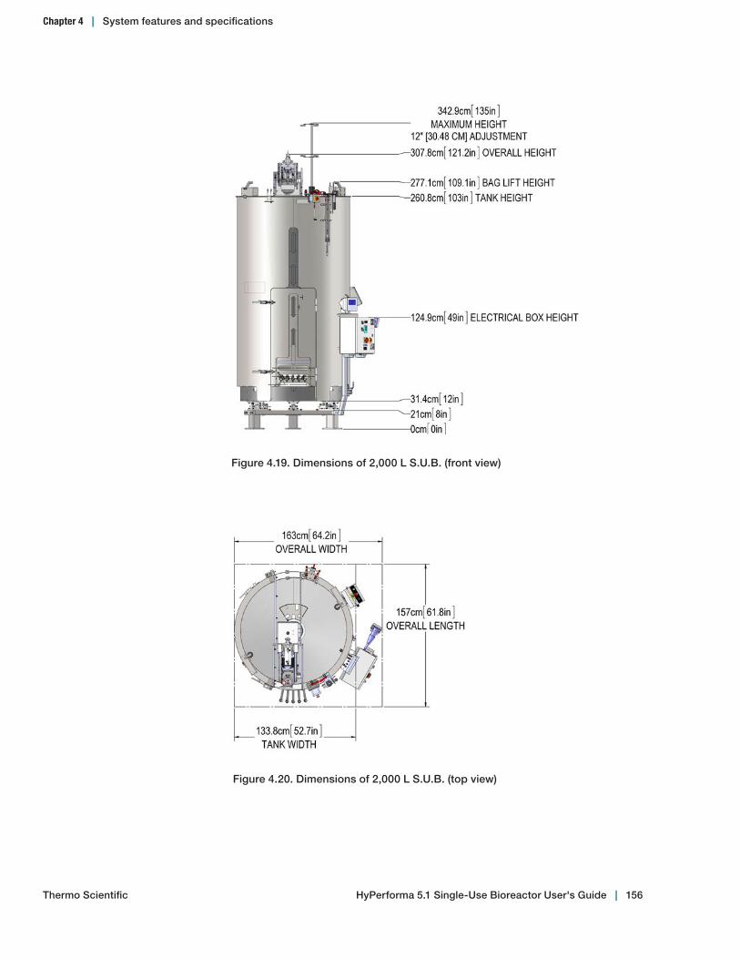
Figure 4.19. Dimensions of 2,000 L S.U.B. (front view)
Figure 4.20. Dimensions of 2,000 L S.U.B. (top view)
Chapter 4 | System features and specifications
HyPerforma 5.1 Single‑Use Bioreactor User's Guide | 156Thermo Scientific
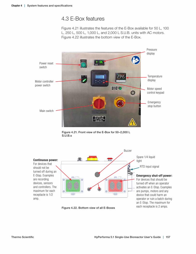
4.3 E-Box features
Figure 4.21 illustrates the features of the E-Box available for 50 L, 100 L, 250 L, 500 L, 1,000 L, and 2,000 L S.U.B. units with AC motors. Figure 4.22 illustrates the bottom view of the E-Box.
Power reset switch
Motor controller power switch
Motor speed control keypad
Main switch
Emergency stop button
Pressure display
Figure 4.21. Front view of the E‑Box for 50–2,000 L S.U.B.s
Temperature display
Spare 1/4 liquid tight
RTD input signal
Emergency shut-off power: For devices that should be turned off when an operator activates an E-Stop. Examples are pumps, motors and any device that could harm an operator or ruin a batch during an E-Stop. The maximum for each receptacle is 2 amps.
Buzzer
Continuous power: For devices that should not be turned off during an E-Stop. Examples are recording devices, sensors and controllers. The maximum for each receptacle is 1/2 amp.
Figure 4.22. Bottom view of all E‑Boxes
Thermo Scientific HyPerforma 5.1 Single‑Use Bioreactor User's Guide | 157
Chapter 4 | System features and specifications

Impeller
8
3 9
1
24–7
14
1512–13
10
11
4.4 BPC specifications
The following figures and tables provide specification information for 5.1 BPCs in 50, 100, 250, 500, 1,000, and 2,000 L sizes.
5.1 S.U.B. 50 L BPC with AseptiQuik connector portsSpecification information for the numbered items in Figure 4.23 is located in Table 4.13 on the following page.
Front face
Back face
Figure 4.23. Front and back faces of 50 L S.U.B. BPC
HyPerforma 5.1 Single‑Use Bioreactor User's Guide | 158Thermo Scientific
Chapter 4 | System features and specifications

Table 4.13. 50 L BPC specification information.
Item Description Tubing set (ID x OD x length) End treatment
1Inoculum addition
6.4 mm (1/4 in.) x 11.1 mm (7/16 in.) C-Flex tubing x 152 cm (60 in.) Reduced to 3.2 mm (1/8 in.) x 6.4 mm (1/4 in.) C-Flex tubing x 30 cm(12 in.)
Plugged
2Overlay gas sparger
6.4 mm (1/4 in.) x 11.1 mm (7/16 in.) C-Flex tubing x 15 cm (6 in.)
Hydrophobic vent filter with Emflon II, connected to 15 cm (6 in.) C-Flex tubing
3Cross flow sparger
6.4 mm (1/4 in.) x 11.1 mm (7/16 in.) C-Flex tubing x 8 cm (3 in.) connected to check valve and 6.4 mm (1/4 in.) x 11.1 mm (7/16 in.) C-Flex tubing x 183 cm (72 in.)
Meissner Steridyne 50 mm (1.97 in.) filter
4–7 Probe ports (4) 12.7 mm (1/2 in.) tube portsCPC AseptiQuik aseptic connectors
8Bottom drain harvest
12.7 mm (1/2 in.) x 19.1 mm (3/4 in.) C-Flex tubing x 152 cm (60 in.)Reduced to 9.5 mm (3/8 in.) x 15.9 mm (5/8 in.) C-Flex tubing x 30 cm(12 in.) Splits to 6.4 mm (1/4 in.) x 11.1 mm (7/16 in.) C-Flex Tubing x 30 cm (12 in.) Reduced to 3.2 mm (1/8 in.) x 6.4 mm (1/4 in.) C-Flex tubing x 30 cm(12 in.) and 9.5 mm (3/8 in.) x 15.9 mm (5/8 in.) C-Flex tubing x 30 cm (12 in.)
Plugged and9.5 mm (3/8 in.) MPC insert
9Thermowell/small volume sample
Thermowell adapter for 3.2 mm (1/8 in.) diameter RTD and3.2 mm (1/8 in.) x 6.4 mm (1/4 in.) C-Flex tubing x 46 cm (18 in.)
Luer lock and SterilEnz pouch with injection siteassembly
10 Base addition6.4 mm (1/4 in.) x 11.1 mm (7/16 in.) C-Flex tubing x 15 cm (6 in.)Reduced to 3.2 mm (1/8 in.) x 6.4 mm (1/4 in.) C-Flex tubing x 152 cm(60 in.)
Plugged
11Pressure sensor port
12.7 mm (1/2 in.) x 19.1 mm (3/4 in.) C-Flex tubing x 8 cm (3 in.)CPC AseptiQuik aseptic connector
12–13
Feed lines
9.5 mm (3/8 in.) x 15.9 mm (5/8 in.) C-Flex tubing x 152 cm (60 in.)Splits to 6.4 mm (1/4 in.) x 11.1 mm (7/16 in.) C-Flex tubing x 30 cm (12 in.) Reduced to 3.2 mm (1/8 in.) x 6.4 mm (1/4 in.) C-Flex tubing x 30 cm (12 in.) and 9.5 mm (3/8 in.) x 15.9 mm (5/8 in.) C-Flex tubing x 30 cm (12 in.)
SteriEnz pouch with injection siteassembly and 9.5 mm (3/8 in.) MPC body
14 Exhaust line12.7 mm (1/2 in.) x 19.1 mm (3/4 in.) C-Flex tubing x 20 cm (8 in.)Connected to 12.7 mm (1/2 in.) x 19.1 mm (3/4 in.) C-Flex tubing x 15 cm (6 in.) and 12.7 mm (1/2 in.) x 19.1 mm (3/4 in.) C-Flex tubing x 25 cm (10 in.)
CPC AseptiQuik aseptic connector—Pall Kleenpak 0.2 micron exhaust vent filter
15
Drilled hole sparger 8.9 cm (3.5 in.) disk with 360 x 0.178 mm (0.007 in.) holes
6.4 mm (1/4 in.) x 11.1 mm (7/16 in.) C-Flex tubing x 8 cm (3 in.)Connected to check valve and 6.4 mm (1/4 in.) x 11.1 mm (7/16 in.) C-Flex tubing x 97 cm (38 in.)
Meissner Steridyne 0.2 micron hydrophobic filter connected to 15 cm (6 in.) C-Flex
HyPerforma 5.1 Single‑Use Bioreactor User's Guide | 159Thermo Scientific
Chapter 4 | System features and specifications
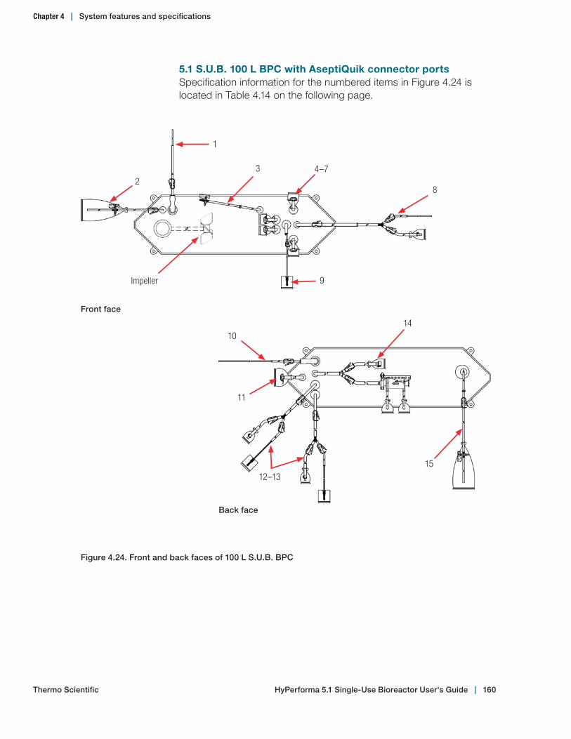
5.1 S.U.B. 100 L BPC with AseptiQuik connector portsSpecification information for the numbered items in Figure 4.24 is located in Table 4.14 on the following page.
Impeller
8
3
9
1
24–7
14
1512–13
10
11
Figure 4.24. Front and back faces of 100 L S.U.B. BPC
Front face
Back face
HyPerforma 5.1 Single‑Use Bioreactor User's Guide | 160Thermo Scientific
Chapter 4 | System features and specifications

Table 4.14. 100 L BPC specification information.
Item Description Tubing set (ID x OD x length) End treatment
1Inoculum addition
6.4 mm (1/4 in.) x 11.1 mm (7/16 in.) C-Flex tubing x 152 cm (60 in.) Reduced to 3.2 mm (1/8 in.) x 6.4 mm (1/4 in.) C-Flex tubing x 30 cm(12 in.)
Plugged
2Overlay gas sparger
6.4 mm (1/4 in.) x 11.1 mm (7/16 in.) C-Flex tubing x 20 cm (8 in.)
Hydrophobic vent filter with Emflon II, connected to 15 cm (6 in.) C-Flex tubing
3Cross flow sparger
6.4 mm (1/4 in.) x 11.1 mm (7/16 in.) C-Flex tubing x 8 cm (3 in.) connected to check valve and 6.4 mm (1/4 in.) x 11.1 mm (7/16 in.) C-Flex tubing x 183 cm (72 in.)
Meissner Steridyne 50 mm (1.97 in.) filter
4–7 Probe ports (4) 12.7 mm (1/2 in.) tube portsCPC AseptiQuik aseptic connectors
8Bottom drain harvest
12.7 mm (1/2 in.) x 19.1 mm (3/4 in.) C-Flex tubing x 152 cm (60 in.)Reduced to 9.5 mm (3/8 in.) x 15.9 mm (5/8 in.) C-Flex tubing x 30 cm(12 in.) Splits to 6.4 mm (1/4 in.) x 11.1 mm (7/16 in.) C-Flex tubing x 30 cm (12 in.) Reduced to 3.2 mm (1/8 in.) x 6.4 mm (1/4 in.) C-Flex tubing x 30 cm(12 in.) and 9.5 mm (3/8 in.) x 15.9 mm (5/8 in.) C-Flex tubing x 30 cm (12 in.)
Plugged and9.5 mm (3/8 in.) MPC insert
9Thermowell/small volume sample
Thermowell adapter for 6.4 mm (1/4 in.) diameter RTD and3.2 mm (1/8 in.) x 6.4 mm (1/4 in.) C-Flex tubing x 46 cm (18 in.)
SterilEnz pouch with injection siteassembly
10 Base addition6.4 mm (1/4 in.) x 11.1 mm (7/16 in.) C-Flex tubing x 15 cm (6 in.)Reduced to 3.2 mm (1/8 in.) x 6.4 mm (1/4 in.) C-Flex tubing x 152 cm(60 in.)
Plugged
11Pressure sensor port
12.7 mm (1/2 in.) x 19.1 mm (3/4 in.) C-Flex tubing x 8 cm (3 in.)CPC AseptiQuik aseptic connector
12–13
Feed lines
9.5 mm (3/8 in.) x 15.9 mm (5/8 in.) C-Flex tubing x 152 cm (60 in.)Splits to 6.4 mm (1/4 in.) x 11.1 mm (7/16 in.) C-Flex tubing x 30 cm (12 in.) Reduced to 3.2 mm (1/8 in.) x 6.4 mm (1/4 in.) C-Flex tubing x 30 cm (12 in.) and 9.5 mm (3/8 in.) x 15.9 mm (5/8 in.) C-Flex tubing x 30 cm (12 in.)
SteriEnz pouch with injection siteassembly and 9.5 mm (3/8 in.) MPC body
14 Exhaust line12.7 mm (1/2 in.) x 19.1 mm (3/4 in.) C-Flex tubing x 20 cm (8 in.)Connected to 12.7 mm (1/2 in.) x 19.1 mm (3/4 in.) C-Flex tubing x 15 cm (6 in.) and 12.7 mm (1/2 in.) x 19.1 mm (3/4 in.) C-Flex tubing x 25 cm (10 in.)
CPC AseptiQuik aseptic connector—Pall Kleenpak 0.2 micron exhaust vent filter
15
Drilled hole sparger 8.9 cm (3.5 in.) disk with 570 x 0.178 mm (0.007 in.) holes
6.4 mm (1/4 in.) x 11.1 mm (7/16 in.) C-Flex tubing x 8 cm (3 in.)Connected to check valve and 6.4 mm (1/4 in.) x 11.1 mm (7/16 in.) C-Flex tubing x 114 cm (45 in.)
Meissner Steridyne 0.2 micron hydrophobic filter connected to 15 cm (6 in.) C-Flex
HyPerforma 5.1 Single‑Use Bioreactor User's Guide | 161Thermo Scientific
Chapter 4 | System features and specifications
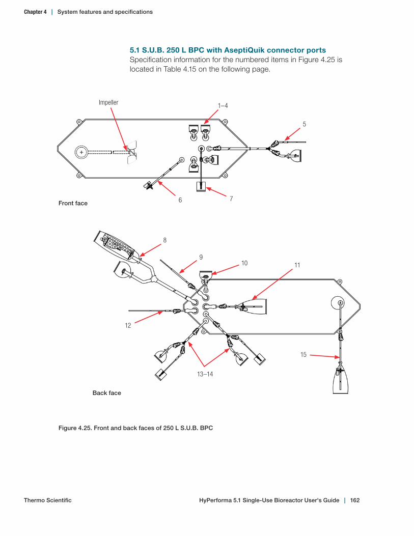
5.1 S.U.B. 250 L BPC with AseptiQuik connector portsSpecification information for the numbered items in Figure 4.25 is located in Table 4.15 on the following page.
Impeller
5
6 7
1–4
Figure 4.25. Front and back faces of 250 L S.U.B. BPC
Front face
10
15
13–14
10
119
12
8
Back face
HyPerforma 5.1 Single‑Use Bioreactor User's Guide | 162Thermo Scientific
Chapter 4 | System features and specifications
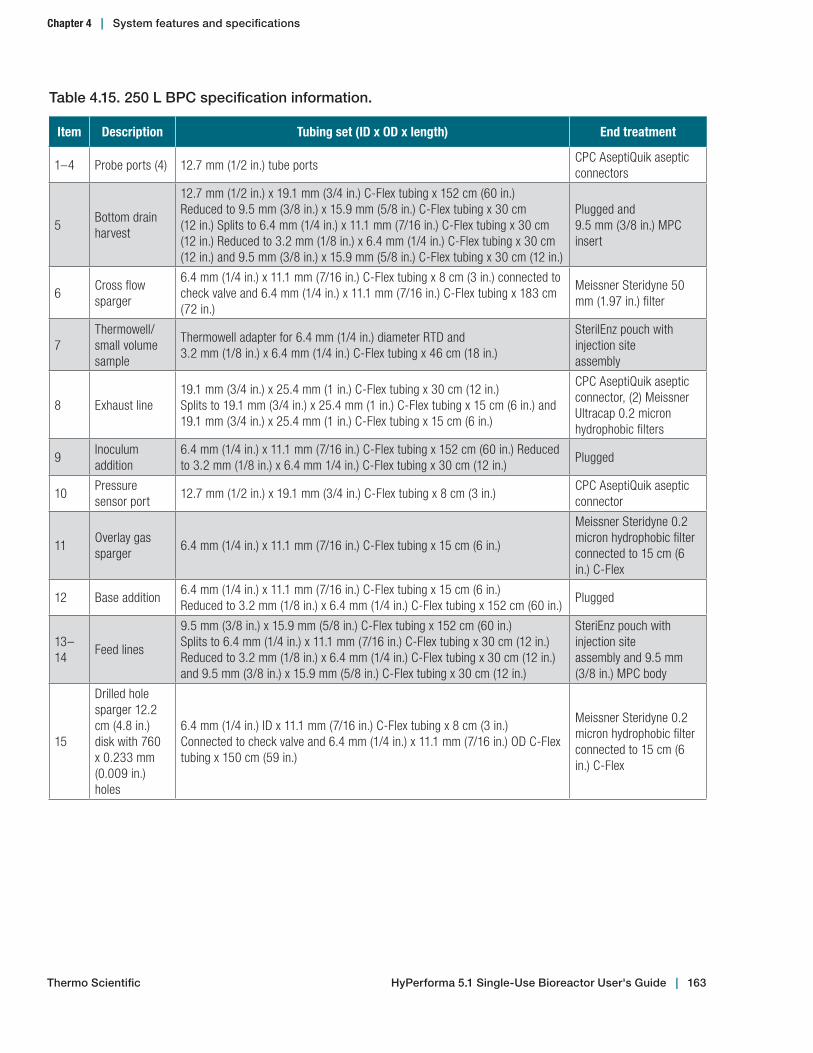
Table 4.15. 250 L BPC specification information.
Item Description Tubing set (ID x OD x length) End treatment
1–4 Probe ports (4) 12.7 mm (1/2 in.) tube portsCPC AseptiQuik asepticconnectors
5Bottom drain harvest
12.7 mm (1/2 in.) x 19.1 mm (3/4 in.) C-Flex tubing x 152 cm (60 in.)Reduced to 9.5 mm (3/8 in.) x 15.9 mm (5/8 in.) C-Flex tubing x 30 cm(12 in.) Splits to 6.4 mm (1/4 in.) x 11.1 mm (7/16 in.) C-Flex tubing x 30 cm (12 in.) Reduced to 3.2 mm (1/8 in.) x 6.4 mm (1/4 in.) C-Flex tubing x 30 cm(12 in.) and 9.5 mm (3/8 in.) x 15.9 mm (5/8 in.) C-Flex tubing x 30 cm (12 in.)
Plugged and9.5 mm (3/8 in.) MPC insert
6Cross flow sparger
6.4 mm (1/4 in.) x 11.1 mm (7/16 in.) C-Flex tubing x 8 cm (3 in.) connected to check valve and 6.4 mm (1/4 in.) x 11.1 mm (7/16 in.) C-Flex tubing x 183 cm (72 in.)
Meissner Steridyne 50 mm (1.97 in.) filter
7Thermowell/small volume sample
Thermowell adapter for 6.4 mm (1/4 in.) diameter RTD and3.2 mm (1/8 in.) x 6.4 mm (1/4 in.) C-Flex tubing x 46 cm (18 in.)
SterilEnz pouch with injection siteassembly
8 Exhaust line19.1 mm (3/4 in.) x 25.4 mm (1 in.) C-Flex tubing x 30 cm (12 in.)Splits to 19.1 mm (3/4 in.) x 25.4 mm (1 in.) C-Flex tubing x 15 cm (6 in.) and 19.1 mm (3/4 in.) x 25.4 mm (1 in.) C-Flex tubing x 15 cm (6 in.)
CPC AseptiQuik aseptic connector, (2) Meissner Ultracap 0.2 micron hydrophobic filters
9Inoculum addition
6.4 mm (1/4 in.) x 11.1 mm (7/16 in.) C-Flex tubing x 152 cm (60 in.) Reduced to 3.2 mm (1/8 in.) x 6.4 mm 1/4 in.) C-Flex tubing x 30 cm (12 in.)
Plugged
10Pressure sensor port
12.7 mm (1/2 in.) x 19.1 mm (3/4 in.) C-Flex tubing x 8 cm (3 in.)CPC AseptiQuik aseptic connector
11Overlay gas sparger
6.4 mm (1/4 in.) x 11.1 mm (7/16 in.) C-Flex tubing x 15 cm (6 in.)
Meissner Steridyne 0.2 micron hydrophobic filter connected to 15 cm (6 in.) C-Flex
12 Base addition6.4 mm (1/4 in.) x 11.1 mm (7/16 in.) C-Flex tubing x 15 cm (6 in.)Reduced to 3.2 mm (1/8 in.) x 6.4 mm (1/4 in.) C-Flex tubing x 152 cm (60 in.)
Plugged
13–14
Feed lines
9.5 mm (3/8 in.) x 15.9 mm (5/8 in.) C-Flex tubing x 152 cm (60 in.)Splits to 6.4 mm (1/4 in.) x 11.1 mm (7/16 in.) C-Flex tubing x 30 cm (12 in.) Reduced to 3.2 mm (1/8 in.) x 6.4 mm (1/4 in.) C-Flex tubing x 30 cm (12 in.) and 9.5 mm (3/8 in.) x 15.9 mm (5/8 in.) C-Flex tubing x 30 cm (12 in.)
SteriEnz pouch with injection siteassembly and 9.5 mm (3/8 in.) MPC body
15
Drilled hole sparger 12.2 cm (4.8 in.) disk with 760 x 0.233 mm (0.009 in.) holes
6.4 mm (1/4 in.) ID x 11.1 mm (7/16 in.) C-Flex tubing x 8 cm (3 in.)Connected to check valve and 6.4 mm (1/4 in.) x 11.1 mm (7/16 in.) OD C-Flex tubing x 150 cm (59 in.)
Meissner Steridyne 0.2 micron hydrophobic filter connected to 15 cm (6 in.) C-Flex
HyPerforma 5.1 Single‑Use Bioreactor User's Guide | 163Thermo Scientific
Chapter 4 | System features and specifications

5.1 S.U.B. 500 L BPC with AseptiQuik connector portsSpecification information for the numbered items in Figure 4.26 is located in Table 4.16 on the following page.
Impeller
6
78
1–5
Figure 4.26. Front and back faces of 500 L S.U.B. BPC
Front face
1514
10
11
9
12–13
16
Back face
HyPerforma 5.1 Single‑Use Bioreactor User's Guide | 164Thermo Scientific
Chapter 4 | System features and specifications

Table 4.16. 500 L BPC specification information.
Item Description Tubing set (ID x OD x length) End treatment
1–5 Probe ports (4) 12.7 mm (1/2 in.) tube portsCPC AseptiQuik asepticconnectors
6Bottom drain harvest
12.7 mm (1/2 in.) x 19.1 mm (3/4 in.) C-Flex tubing x 152 cm (60 in.)Reduced to 9.5 mm (3/8 in.) x 15.9 mm (5/8 in.) C-Flex tubing x 30 cm(12 in.) Splits to 6.4 mm (1/4 in.) x 11.1 mm (7/16 in.) C-Flex tubing x 30 cm (12 in.) Reduced to 3.2 mm (1/8 in.) x 6.4 mm (1/4 in.) C-Flex tubing x 30 cm(12 in.) and 9.5 mm (3/8 in.) x 15.9 mm (5/8 in.) C-Flex tubing x 30 cm (12 in.)
Plugged and9.5 mm (3/8 in.) MPC insert
7Cross flow sparger
6.4 mm (1/4 in.) x 11.1 mm (7/16 in.) C-Flex tubing x 8 cm (3 in.) connected to check valve and 6.4 mm (1/4 in.) x 11.1 mm (7/16 in.) C-Flex tubing x 183 cm (72 in.)
Meissner Steridyne 50 mm (1.97 in.) filter
8Thermowell/small volume sample
Thermowell adapter for 6.4 mm (1/4 in.) diameter RTD and3.2 mm (1/8 in.) x 6.4 mm (1/4 in.) C-Flex tubing x 46 cm (18 in.)
SterilEnz pouch with injection siteassembly
9 Exhaust line19.1 mm (3/4 in.) x 25.4 mm (1 in.) C-Flex tubing x 30 cm (12 in.)Splits to 19.1 mm (3/4 in.) x 25.4 mm (1 in.) C-Flex tubing x 15 cm (6 in.) and 19.1 mm (3/4 in.) x 25.4 mm (1 in.) C-Flex tubing x 15 cm (6 in.)
Meissner Ultracap 0.2 micron hydrophobic filters
10Overlay gas sparger
6.4 mm (1/4 in.) x 11.1 mm (7/16 in.) C-Flex tubing x 15 cm (6 in.)Hydrophobic vent filter with Emflon II, connected to 15 cm (6 in.) C-Flex
11Pressure sensor port
12.7 mm (1/2 in.) x 19.1 mm (3/4 in.) C-Flex tubing x 8 cm (3 in.)CPC AseptiQuik aseptic connector
12–13
Feed lines
9.5 mm (3/8 in.) x 15.9 mm (5/8 in.) C-Flex tubing x 213 cm (84 in.)Splits to 6.4 mm (1/4 in.) x 11.1 mm (7/16 in.) C-Flex tubing x 30 cm (12 in.) Reduced to 3.2 mm (1/8 in.) x 6.4 mm (1/4 in.) C-Flex tubing x 30 cm (12 in.) and 9.5 mm (3/8 in.) x 15.9 mm (5/8 in.) C-Flex tubing x 30 cm (12 in.)
SteriEnz pouch with injection siteassembly and 9.5 mm (3/8 in.) MPC body
14 Base addition6.4 mm (1/4 in.) x 11.1 mm (7/16 in.) C-Flex tubing x 213 cm (84 in.)Reduced to 3.2 mm (1/8 in.) x 6.4 mm (1/4 in.) C-Flex tubing x 30 cm(12 in.)
Plugged
15Inoculum addition
6.4 mm (1/4 in.) x 11.1 mm (7/16 in.) C-Flex tubing x 15 cm (6 in.) Reduced to 3.2 mm (1/8 in.) x 6.4 mm (1/4 in.) C-Flex tubing x 213 cm (84 in.)
Plugged
16
Drilled hole sparger 17.14 cm (6.75 in.) disk with 980 x 0.368 mm (0.014 in.) holes
6.4 mm (1/4 in.) ID x 11.1 mm (7/16 in.) C-Flex tubing x 8 cm (3 in.)Connected to check valve and 6.4 mm (1/4 in.) x 11.1 mm (7/16 in.) OD C-Flex tubing x 97 cm (38 in.)
Kleenpak Emflon 0.2 micron hydrophobic filter connected to 15 cm (6 in.) C-Flex
HyPerforma 5.1 Single‑Use Bioreactor User's Guide | 165Thermo Scientific
Chapter 4 | System features and specifications
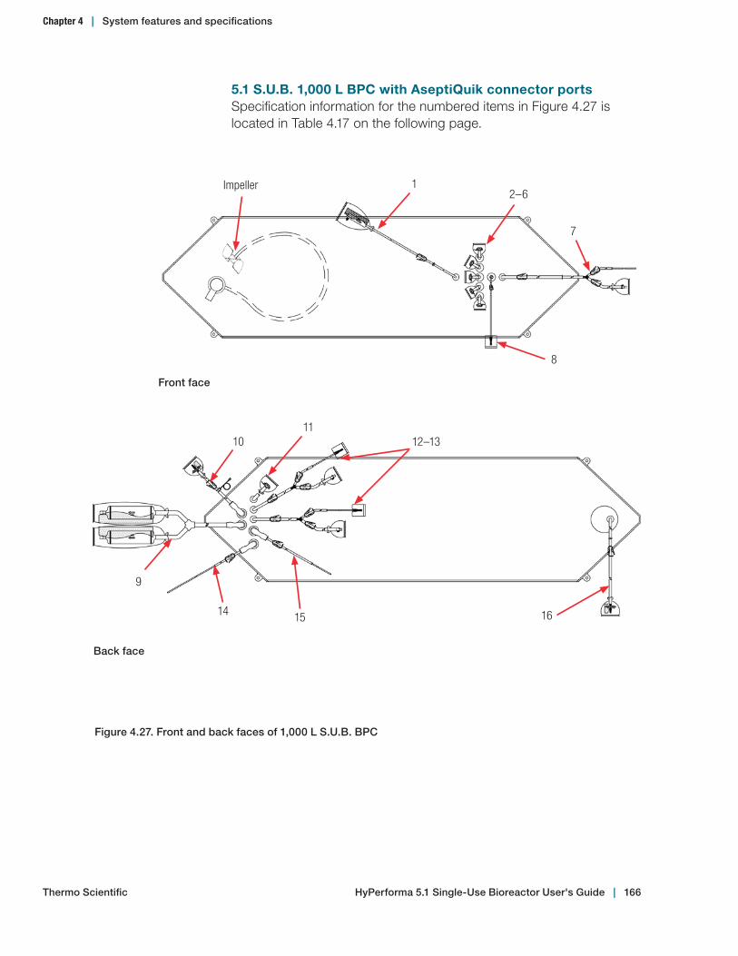
5.1 S.U.B. 1,000 L BPC with AseptiQuik connector portsSpecification information for the numbered items in Figure 4.27 is located in Table 4.17 on the following page.
Impeller
7
1
8
2–6
Figure 4.27. Front and back faces of 1,000 L S.U.B. BPC
Front face
1514
1011
9
12–13
16
Back face
HyPerforma 5.1 Single‑Use Bioreactor User's Guide | 166Thermo Scientific
Chapter 4 | System features and specifications
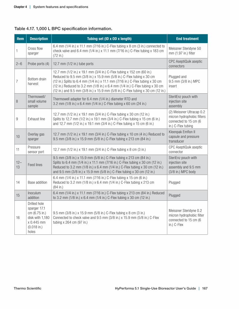
Table 4.17. 1,000 L BPC specification information.
Item Description Tubing set (ID x OD x length) End treatment
1Cross flow sparger
6.4 mm (1/4 in.) x 11.1 mm (7/16 in.) C-Flex tubing x 8 cm (3 in.) connected to check valve and 6.4 mm (1/4 in.) x 11.1 mm (7/16 in.) C-Flex tubing x 183 cm (72 in.)
Meissner Steridyne 50 mm (1.97 in.) filter
2–6 Probe ports (4) 12.7 mm (1/2 in.) tube portsCPC AseptiQuik aseptic connectors
7Bottom drain harvest
12.7 mm (1/2 in.) x 19.1 mm (3/4 in.) C-Flex tubing x 152 cm (60 in.)Reduced to 9.5 mm (3/8 in.) x 15.9 mm (5/8 in.) C-Flex tubing x 30 cm(12 in.) Splits to 6.4 mm (1/4 in.) x 11.1 mm (7/16 in.) C-Flex tubing x 30 cm (12 in.) Reduced to 3.2 mm (1/8 in.) x 6.4 mm (1/4 in.) C-Flex tubing x 30 cm(12 in.) and 9.5 mm (3/8 in.) x 15.9 mm (5/8 in.) C-Flex tubing x 30 cm (12 in.)
Plugged and9.5 mm (3/8 in.) MPC insert
8Thermowell/small volume sample
Thermowell adapter for 6.4 mm (1/4 in.) diameter RTD and3.2 mm (1/8 in.) x 6.4 mm (1/4 in.) C-Flex tubing x 60 cm (24 in.)
SterilEnz pouch with injection siteassembly
9 Exhaust line12.7 mm (1/2 in.) x 19.1 mm (3/4 in.) C-Flex tubing x 30 cm (12 in.)Splits to 12.7 mm (1/2 in.) x 19.1 mm (3/4 in.) C-Flex tubing x 15 cm (6 in.) and 12.7 mm (1/2 in.) x 19.1 mm (3/4 in.) C-Flex tubing x 15 cm (6 in.)
(2) Meissner Ultracap 0.2 micron hydrophobic filters connected to 15 cm (6 in.) C-Flex tubing
10Overlay gas sparger
12.7 mm (1/2 in.) x 19.1 mm (3/4 in.) C-Flex tubing x 10 cm (4 in.) Reduced to 9.5 mm (3/8 in.) x 15.9 mm (5/8 in.) C-Flex tubing x 213 cm (84 in.)
Kleenpak Emflon II capsule and pressure transducer
11Pressure sensor port
12.7 mm (1/2 in.) x 19.1 mm (3/4 in.) C-Flex tubing x 8 cm (3 in.)CPC AseptiQuik aseptic connector
12–13
Feed lines
9.5 mm (3/8 in.) x 15.9 mm (5/8 in.) C-Flex tubing x 213 cm (84 in.)Splits to 6.4 mm (1/4 in.) x 11.1 mm (7/16 in.) C-Flex tubing x 30 cm (12 in.) Reduced to 3.2 mm (1/8 in.) x 6.4 mm (1/4 in.) C-Flex tubing x 30 cm (12 in.) and 9.5 mm (3/8 in.) x 15.9 mm (5/8 in.) C-Flex tubing x 30 cm (12 in.)
SteriEnz pouch with injection siteassembly and 9.5 mm (3/8 in.) MPC body
14 Base addition6.4 mm (1/4 in.) x 11.1 mm (7/16 in.) C-Flex tubing x 15 cm (6 in.)Reduced to 3.2 mm (1/8 in.) x 6.4 mm (1/4 in.) C-Flex tubing x 213 cm(84 in.)
Plugged
15Inoculum addition
6.4 mm (1/4 in.) x 11.1 mm (7/16 in.) C-Flex tubing x 213 cm (84 in.) Reduced to 3.2 mm (1/8 in.) x 6.4 mm (1/4 in.) C-Flex tubing x 30 cm (12 in.)
Plugged
16
Drilled hole sparger 17.1 cm (6.75 in.) disk with 1,180 x 0.445 mm (0.018 in.) holes
9.5 mm (3/8 in.) x 15.9 mm (5/8 in.) C-Flex tubing x 8 cm (3 in.)Connected to check valve and 9.5 mm (3/8 in.) x 15.9 mm (5/8 in.) C-Flex tubing x 264 cm (97 in.)
Meissner Steridyne 0.2 micron hydrophobic filter connected to 15 cm (6 in.) C-Flex
HyPerforma 5.1 Single‑Use Bioreactor User's Guide | 167Thermo Scientific
Chapter 4 | System features and specifications
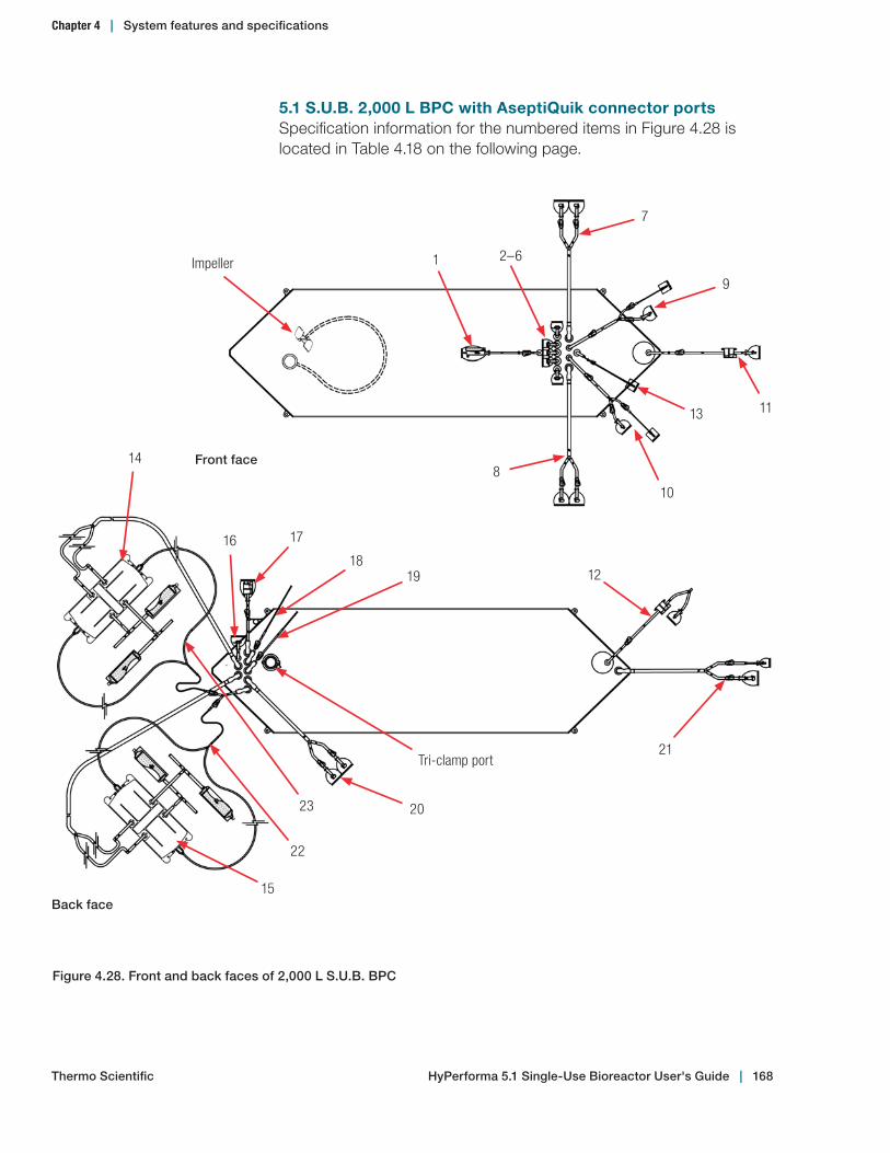
5.1 S.U.B. 2,000 L BPC with AseptiQuik connector portsSpecification information for the numbered items in Figure 4.28 is located in Table 4.18 on the following page.
Figure 4.28. Front and back faces of 2,000 L S.U.B. BPC
Back face
Impeller
7
1
10
2–6
9
1113
8Front face
20
22
171618
12
14
19
21Tri-clamp port
15
23
HyPerforma 5.1 Single‑Use Bioreactor User's Guide | 168Thermo Scientific
Chapter 4 | System features and specifications
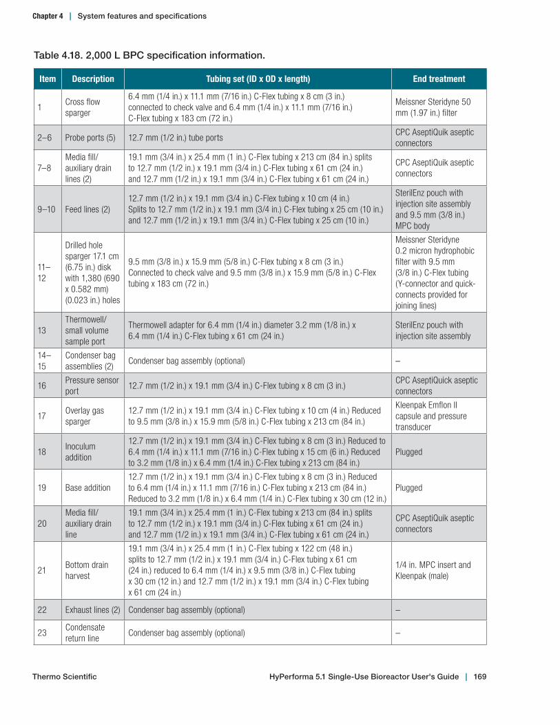
Table 4.18. 2,000 L BPC specification information.
Item Description Tubing set (ID x OD x length) End treatment
1Cross flow sparger
6.4 mm (1/4 in.) x 11.1 mm (7/16 in.) C-Flex tubing x 8 cm (3 in.)connected to check valve and 6.4 mm (1/4 in.) x 11.1 mm (7/16 in.)C-Flex tubing x 183 cm (72 in.)
Meissner Steridyne 50 mm (1.97 in.) filter
2–6 Probe ports (5) 12.7 mm (1/2 in.) tube portsCPC AseptiQuik aseptic connectors
7–8Media fill/auxiliary drain lines (2)
19.1 mm (3/4 in.) x 25.4 mm (1 in.) C-Flex tubing x 213 cm (84 in.) splitsto 12.7 mm (1/2 in.) x 19.1 mm (3/4 in.) C-Flex tubing x 61 cm (24 in.)and 12.7 mm (1/2 in.) x 19.1 mm (3/4 in.) C-Flex tubing x 61 cm (24 in.)
CPC AseptiQuik aseptic connectors
9–10 Feed lines (2)12.7 mm (1/2 in.) x 19.1 mm (3/4 in.) C-Flex tubing x 10 cm (4 in.) Splits to 12.7 mm (1/2 in.) x 19.1 mm (3/4 in.) C-Flex tubing x 25 cm (10 in.) and 12.7 mm (1/2 in.) x 19.1 mm (3/4 in.) C-Flex tubing x 25 cm (10 in.)
SterilEnz pouch withinjection site assemblyand 9.5 mm (3/8 in.)MPC body
11–12
Drilled hole sparger 17.1 cm (6.75 in.) disk with 1,380 (690 x 0.582 mm) (0.023 in.) holes
9.5 mm (3/8 in.) x 15.9 mm (5/8 in.) C-Flex tubing x 8 cm (3 in.)Connected to check valve and 9.5 mm (3/8 in.) x 15.9 mm (5/8 in.) C-Flex tubing x 183 cm (72 in.)
Meissner Steridyne0.2 micron hydrophobicfilter with 9.5 mm (3/8 in.) C-Flex tubing (Y-connector and quick-connects provided for joining lines)
13Thermowell/small volume sample port
Thermowell adapter for 6.4 mm (1/4 in.) diameter 3.2 mm (1/8 in.) x6.4 mm (1/4 in.) C-Flex tubing x 61 cm (24 in.)
SterilEnz pouch withinjection site assembly
14–15
Condenser bag assemblies (2)
Condenser bag assembly (optional) –
16Pressure sensor port
12.7 mm (1/2 in.) x 19.1 mm (3/4 in.) C-Flex tubing x 8 cm (3 in.)CPC AseptiQuick aseptic connectors
17Overlay gas sparger
12.7 mm (1/2 in.) x 19.1 mm (3/4 in.) C-Flex tubing x 10 cm (4 in.) Reduced to 9.5 mm (3/8 in.) x 15.9 mm (5/8 in.) C-Flex tubing x 213 cm (84 in.)
Kleenpak Emflon II capsule and pressure transducer
18Inoculum addition
12.7 mm (1/2 in.) x 19.1 mm (3/4 in.) C-Flex tubing x 8 cm (3 in.) Reduced to 6.4 mm (1/4 in.) x 11.1 mm (7/16 in.) C-Flex tubing x 15 cm (6 in.) Reduced to 3.2 mm (1/8 in.) x 6.4 mm (1/4 in.) C-Flex tubing x 213 cm (84 in.)
Plugged
19 Base addition12.7 mm (1/2 in.) x 19.1 mm (3/4 in.) C-Flex tubing x 8 cm (3 in.) Reduced to 6.4 mm (1/4 in.) x 11.1 mm (7/16 in.) C-Flex tubing x 213 cm (84 in.) Reduced to 3.2 mm (1/8 in.) x 6.4 mm (1/4 in.) C-Flex tubing x 30 cm (12 in.)
Plugged
20Media fill/auxiliary drain line
19.1 mm (3/4 in.) x 25.4 mm (1 in.) C-Flex tubing x 213 cm (84 in.) splitsto 12.7 mm (1/2 in.) x 19.1 mm (3/4 in.) C-Flex tubing x 61 cm (24 in.)and 12.7 mm (1/2 in.) x 19.1 mm (3/4 in.) C-Flex tubing x 61 cm (24 in.)
CPC AseptiQuik aseptic connectors
21Bottom drain harvest
19.1 mm (3/4 in.) x 25.4 mm (1 in.) C-Flex tubing x 122 cm (48 in.)splits to 12.7 mm (1/2 in.) x 19.1 mm (3/4 in.) C-Flex tubing x 61 cm(24 in.) reduced to 6.4 mm (1/4 in.) x 9.5 mm (3/8 in.) C-Flex tubingx 30 cm (12 in.) and 12.7 mm (1/2 in.) x 19.1 mm (3/4 in.) C-Flex tubingx 61 cm (24 in.)
1/4 in. MPC insert and Kleenpak (male)
22 Exhaust lines (2) Condenser bag assembly (optional) –
23Condensate return line
Condenser bag assembly (optional) –
HyPerforma 5.1 Single‑Use Bioreactor User's Guide | 169Thermo Scientific
Chapter 4 | System features and specifications
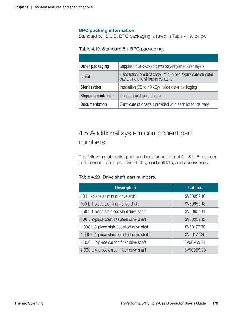
BPC packing informationStandard 5.1 S.U.B. BPC packaging is listed in Table 4.19, below.
4.5 Additional system component part numbers
The following tables list part numbers for additional 5.1 S.U.B. system components, such as drive shafts, load cell kits, and accessories.
Table 4.19. Standard 5.1 BPC packaging.
Outer packaging Supplied "flat-packed"; two polyethylene outer layers
Label Description, product code, lot number, expiry date on outer packaging and shipping container
Sterilization Irradiation (25 to 40 kGy) inside outer packaging
Shipping container Durable cardboard carton
Documentation Certificate of Analysis provided with each lot for delivery
Table 4.20. Drive shaft part numbers.
Description Cat. no.
50 L 1-piece aluminum drive shaft SV50959.10
100 L 1-piece aluminum drive shaft SV50959.18
250 L 1-piece stainless steel drive shaft SV50959.11
500 L 2-piece stainless steel drive shaft SV50959.12
1,000 L 3-piece stainless steel drive shaft SV50177.38
1,000 L 4-piece stainless steel drive shaft SV50177.39
2,000 L 2-piece carbon fiber drive shaft SV50959.21
2,000 L 4-piece carbon fiber drive shaft SV50959.20
HyPerforma 5.1 Single‑Use Bioreactor User's Guide | 170Thermo Scientific
Chapter 4 | System features and specifications
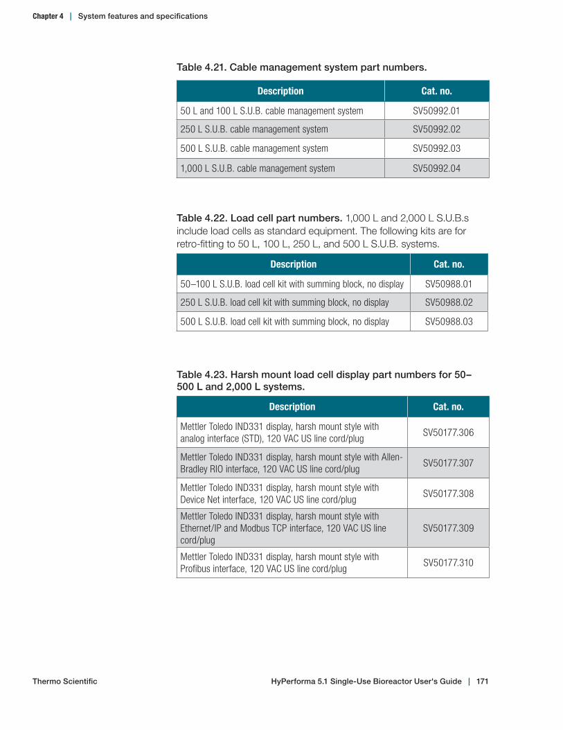
Table 4.21. Cable management system part numbers.
Description Cat. no.
50 L and 100 L S.U.B. cable management system SV50992.01
250 L S.U.B. cable management system SV50992.02
500 L S.U.B. cable management system SV50992.03
1,000 L S.U.B. cable management system SV50992.04
Table 4.22. Load cell part numbers. 1,000 L and 2,000 L S.U.B.s include load cells as standard equipment. The following kits are for retro-fitting to 50 L, 100 L, 250 L, and 500 L S.U.B. systems.
Description Cat. no.
50–100 L S.U.B. load cell kit with summing block, no display SV50988.01
250 L S.U.B. load cell kit with summing block, no display SV50988.02
500 L S.U.B. load cell kit with summing block, no display SV50988.03
Table 4.23. Harsh mount load cell display part numbers for 50–500 L and 2,000 L systems.
Description Cat. no.
Mettler Toledo IND331 display, harsh mount style with analog interface (STD), 120 VAC US line cord/plug
SV50177.306
Mettler Toledo IND331 display, harsh mount style with Allen-Bradley RIO interface, 120 VAC US line cord/plug
SV50177.307
Mettler Toledo IND331 display, harsh mount style with Device Net interface, 120 VAC US line cord/plug
SV50177.308
Mettler Toledo IND331 display, harsh mount style with Ethernet/IP and Modbus TCP interface, 120 VAC US line cord/plug
SV50177.309
Mettler Toledo IND331 display, harsh mount style with Profibus interface, 120 VAC US line cord/plug
SV50177.310
HyPerforma 5.1 Single‑Use Bioreactor User's Guide | 171Thermo Scientific
Chapter 4 | System features and specifications
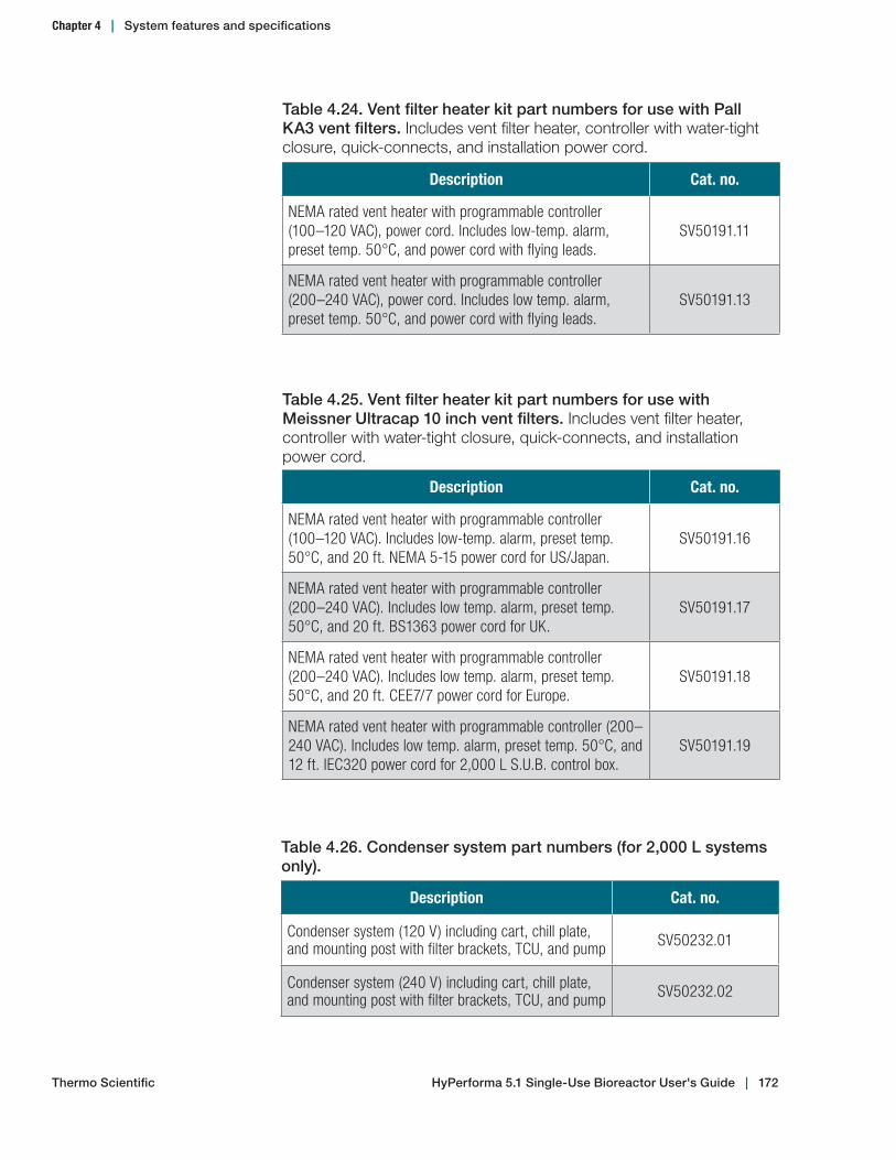
Table 4.24. Vent filter heater kit part numbers for use with Pall KA3 vent filters. Includes vent filter heater, controller with water-tight closure, quick-connects, and installation power cord.
Description Cat. no.
NEMA rated vent heater with programmable controller (100–120 VAC), power cord. Includes low-temp. alarm, preset temp. 50°C, and power cord with flying leads.
SV50191.11
NEMA rated vent heater with programmable controller (200–240 VAC), power cord. Includes low temp. alarm, preset temp. 50°C, and power cord with flying leads.
SV50191.13
Table 4.25. Vent filter heater kit part numbers for use with Meissner Ultracap 10 inch vent filters. Includes vent filter heater, controller with water-tight closure, quick-connects, and installation power cord.
Description Cat. no.
NEMA rated vent heater with programmable controller (100–120 VAC). Includes low-temp. alarm, preset temp. 50°C, and 20 ft. NEMA 5-15 power cord for US/Japan.
SV50191.16
NEMA rated vent heater with programmable controller (200–240 VAC). Includes low temp. alarm, preset temp. 50°C, and 20 ft. BS1363 power cord for UK.
SV50191.17
NEMA rated vent heater with programmable controller (200–240 VAC). Includes low temp. alarm, preset temp. 50°C, and 20 ft. CEE7/7 power cord for Europe.
SV50191.18
NEMA rated vent heater with programmable controller (200–240 VAC). Includes low temp. alarm, preset temp. 50°C, and 12 ft. IEC320 power cord for 2,000 L S.U.B. control box.
SV50191.19
Table 4.26. Condenser system part numbers (for 2,000 L systems only).
Description Cat. no.
Condenser system (120 V) including cart, chill plate, and mounting post with filter brackets, TCU, and pump SV50232.01
Condenser system (240 V) including cart, chill plate, and mounting post with filter brackets, TCU, and pump SV50232.02
HyPerforma 5.1 Single‑Use Bioreactor User's Guide | 172Thermo Scientific
Chapter 4 | System features and specifications
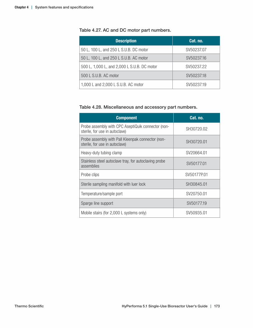
Table 4.27. AC and DC motor part numbers.
Description Cat. no.
50 L, 100 L, and 250 L S.U.B. DC motor SV50237.07
50 L, 100 L, and 250 L S.U.B. AC motor SV50237.16
500 L, 1,000 L, and 2,000 L S.U.B. DC motor SV50237.22
500 L S.U.B. AC motor SV50237.18
1,000 L and 2,000 L S.U.B. AC motor SV50237.19
Table 4.28. Miscellaneous and accessory part numbers.
Component Cat. no.
Probe assembly with CPC AseptiQuik connector (non-sterile, for use in autoclave) SH30720.02
Probe assembly with Pall Kleenpak connector (non-sterile, for use in autoclave) SH30720.01
Heavy-duty tubing clamp SV20664.01
Stainless steel autoclave tray, for autoclaving probe assemblies SV50177.01
Probe clips SV50177P.01
Sterile sampling manifold with luer lock SH30845.01
Temperature/sample port SV20750.01
Sparge line support SV50177.19
Mobile stairs (for 2,000 L systems only) SV50935.01
HyPerforma 5.1 Single‑Use Bioreactor User's Guide | 173Thermo Scientific
Chapter 4 | System features and specifications

Maintenance and troubleshooting
Chapter contents5.1 Maintenance5.2 Troubleshooting and frequently asked questions
5
Thermo Scientific HyPerforma 5.1 Single‑Use Bioreactor User's Guide | 174

5.1 Maintenance
5.1.1 Routine maintenance
Environmental conditions, operating parameters, and adhering to standard operating procedures as outlined in this user’s guide have significant impact upon the useful life of your S.U.B. hardware system. The following guidelines are based upon the standard operating conditions outlined in this user's guide.
High-wear items such as bearings, seals, O-rings, and sterilization valves common to conventional bioreactor systems have been purposefully considered in the design of the construction of the S.U.B. The S.U.B. system is inherently robust and requires low levels of routine maintenance. Taking time between bioreactor runs to clean the exterior of the hardware will improve the appearance and overall longevity of the system. The drive motor is an industrial grade induction motor with a permanently sealed and lubricated gear box. The drive shaft is constructed to wear slightly with use and should be visually inspected after each run. Visual inspection of wear components and following the guidelines listed below will be sufficient to ensure dependable service. Replacement parts are available.
5.1.2 Preventive maintenance
• Lightly coat the drive cap threads with food-grade anti-seize if the motor cap becomes difficult to turn.
• For multiple-segment drive shafts without quick-connects, lightly coat the threads with food-grade anti-seize during assembly.
• Replacement of the mixing motor is recommended every five years, or as needed.
• Refer to the following section of this user's guide for expected drive shaft longevity based on usage.
Replace worn drive shaft head assembly when the hex diameter at its widest location measures equal to or less across the points (Figure 5.1). Diameters are measured at the widest location across the points.
Hex diameter measurement location
Figure 5.1. Shaft head assembly
Chapter 5 | Maintenance and troubleshooting
Thermo Scientific HyPerforma 5.1 Single‑Use Bioreactor User's Guide | 175

Drive shaft longevity and replacementFor 50 L, 100 L, 250 L, 500 L, and 1,000 L S.U.B. systems, we recommend replacing your drive shaft every 360 days of cumulative use.
2,000 L S.U.B. systems experience a greater amount of fatigue-related stress than smaller systems due to the use of a longer drive shaft. If you are operating a 2,000 L S.U.B. at a P/V ratio of 20 W/m3, replace your drive shaft every 180 days of cumulative use. If you are operating a 2,000 L S.U.B. at 40 W/m3, consultation with Thermo Scientific engineers is required. For more information on the use of P/V ratios, see section 3.6.5 of this publication. Note: Operating 2,000 L systems below 50% working volume requires the use of safety interlocks and speed governors. See the Warnings, safety, and warranty information section in the front of this publication for more information.
Note: For warranty purposes, drive shaft use must be documented. A drive shaft use log is provided in Appendix D of this publication.
Under normal operating conditions, replace the drive shaft assembly after 360 days of service, or refer to the drive shaft head wear specifications in Table 5.1, below.
Table 5.1. Drive shaft head hex diameters.
S.U.B. system New hex diameter Minimum hex diameter
50, 100 and 250 L 14.9 mm (0.587 in.) +/- 0.127 mm 14.4 mm (0.566 in.)
500 and 1,000 L 21.3 mm (0.839 in.) +/- 0.127 mm 20.8 mm (0.820 in.)
Chapter 5 | Maintenance and troubleshooting
Thermo Scientific HyPerforma 5.1 Single‑Use Bioreactor User's Guide | 176

5.2 Troubleshooting and frequently asked questions
5.2.1 Hardware operation issues
The S.U.B. will not operate.
Check the power supply.• Verify the position of the main electrical plug connection at the
wall outlet, the main power disconnect, and the emergency stop switch.
• Verify the condition of the main electrical circuit breaker at your facility. If the protection breaker has been tripped, determine the fault condition. The condition may exist where other electrical systems are requiring current loads beyond those allowed by the breaker. The S.U.B. system should be placed on its own electrical circuit.
• Disconnect the main power cord. Inspect the electrical circuit breakers and fuses inside the electrical box of the S.U.B. controller. Determine the fault condition by visual inspection. If the fault condition cannot be determined by visual inspection, contact the manufacturer.
The S.U.B. temperature is below target or slow to respond.
Check the temperature controller and sensor.• Verify that the temperature probe (RTD) is not loose, and has been
fully inserted into the BPC thermowell.• Verify that the thermowell has been filled with sufficient glycerol to
aid in heat transfer.• Verify that the temperature control unit (TCU) is operating, and all
of the ball valves are open.• Verify that the system is filled with a sufficient volume of fluid.
There must be enough media (minimum volume) in the BPC to provide contact with the container. Add more media if the BPC is not touching the heater area.
Issue:
Solution:
Issue:
Solution:
Chapter 5 | Maintenance and troubleshooting
Thermo Scientific HyPerforma 5.1 Single‑Use Bioreactor User's Guide | 177
Noise is being emitted from the mixer assembly.
No action is required.The bearing port assembly supplied with the S.U.B. is an important component in maintaining a sterile environment during cell growth. The special seals used in the S.U.B. may generate some noise during operation, particularly after the first day of operation. This noise may vary in intensity and frequency, but generally has no significant effect on performance or overall durability of the BPC during the intended life of the product.
The mixer controller does not respond to user inputs.
Allow the speed to stabilize before using the keypadinterface.• Adjusting the speed control too rapidly may require several
seconds for speed stabilization.• Wait ten seconds, then attempt to adjust the speed at the keypad
interface.• Verify the position of the input select switch of the variable
frequency drive (VFD). If the toggle switch is not in the middle position, the controller will not be able to receive control inputs from the control keypad on the front panel.
I typically use level sensors to control the volume and feedrate or supplement during a bioreactor run; how would I do this with the S.U.B.?
Use load cells or a scale to control volumes based upon weight.The S.U.B. is not equipped with level sensors. However, the S.U.B. can be set up to allow supplement feeds and volumes to be managed by weight.
How do we ensure that we are using the correct components and setting up the S.U.B. properly for 5:1 mixing?
Before you begin setup, verify that all hardware and components are labeled for 5:1 mixing only (50‑500 L systems only).5.1 S.U.B.s require drive shafts and BPCs that are specifically made for low-volume mixing. For 50-500 L systems, the motor mount, drive shaft, and BPC should be engraved or labeled with "5:1 Mixing" and/or a warning tag. If any of these components are not labeled for 5:1 use, contact your sales representative immediately for a replacement.
Issue:
Solution:
Issue:
Solution:
Issue:
Solution:
Issue:
Solution:
Chapter 5 | Maintenance and troubleshooting
Thermo Scientific HyPerforma 5.1 Single‑Use Bioreactor User's Guide | 178
5.2.2 Cell culture operation issues
Dissolved oxygen readings are low or slow to respond.
Check the physical condition of the dissolved oxygen (DO) probe, the calibration of the probe, and gas flow rate into the S.U.B.• DO probes require routine maintenance; replace the damaged
probe or membrane when necessary.• Verify the DO probe calibration relative to setpoints of zero and
span.• Inspect the line sets connected to direct spargers for restriction
(closed tubing clamp, pinched line, low supply pressure).
Dissolved oxygen readings are erratic or unstable.
Adjust the bioreactor controller to suit the volume of your S.U.B. system.• Many different parameters can affect the ability of a bioreactor
controller to maintain a target setpoint during process control. Modern controllers utilize computer algorithms to adjust targeted parameters; the most common technique is that of a tunable controller that uses variables of the proportional integral derivative (PID). Tuning these PID values to the specific characteristics of the system dynamics will, in most cases, stabilize process parameters to an acceptable level. We recommend that you consult the user guide of the particular bioreactor controller you are using.
• A grounding reference to the media can be created by using a grounding lead between the tank and the body of the stainless steel DO probe or to the stainless steel connector (if present) on the sample line of the BPC.
pH levels are questionable or out of range.
Verify the calibration of the probe and utilize either media or gas buffers.• pH levels can be managed in a similar manner to conventional
bioreactors once calibration of the probe is verified by use of an off-line sample. Carbon dioxide gas sparged through the media or headspace, biocarbonate levels in the media and the addition of liquid titrant solutions all serve to manage the pH balance of the bioreactor environment. See section 3.5.4 for more information on probe calibration.
Issue:
Solution:
Issue:
Solution:
Issue:
Solution:
Chapter 5 | Maintenance and troubleshooting
Thermo Scientific HyPerforma 5.1 Single‑Use Bioreactor User's Guide | 179

• A grounding reference to the media can be created by using a grounding lead between the tank and the body of the stainless steel DO probe or to the stainless steel connector (if present) on the sample line of the BPC.
We are not achieving the cell growth we expected in the S.U.B. while running under our normal bioreactor agitation and sparging rates. What should we do?
Reduce agitation and sparging rates. • Often low cell viability and cell growth can be attributed to
excessive sparging or agitation. We recommend that you reduce the sparge rate compared to what you might use in a conventional bioreactor. Gas flow rates supplied as overlay should also be reduced as much as possible. Too much gas creates excess foam and higher shear conditions. Provide only the level of agitation needed (low viability and lysed cells), reduce agitation speed (cell aggregation and settling), and increase agitation.
• Media formulation can also have a significant effect on cell culture growth in the S.U.B. Surfactants such as Pluronic decrease shear and increase kLa, but at a cost of increased foaming. Thermo Scientific can offer custom media especially for the S.U.B. and your specific cell line(s).
5.2.3 Sparging issues
There is excessive foam in the bioreactor headspace.
Alter the liquid surface tension related to the culture media and/or sparge gas.• A media supplement of antifoam can be used in the S.U.B. These
serve to lower the surface tension of the media and will reduce the presence of foam.
• High sparge rates of air can result in the presence of excessive foam. Testing has shown that sparging with oxygen will typically result in a dramatic reduction of foam in the headspace.
Issue:
Solution:
Issue:
Solution:
Chapter 5 | Maintenance and troubleshooting
Thermo Scientific HyPerforma 5.1 Single‑Use Bioreactor User's Guide | 180

The sparger does not seem to be working although gas is present.
Allow the sparger membrane to purge.• If the S.U.B. is filled with liquid and allowed to sit idle for extended
periods of time without gas being supplied to the sparger, liquid can accumulate between the membrane and check valve. Various media additives may restrict the membrane temporarily. Several minutes of gas pressure being supplied to the sparger should purge the membrane, allowing it to function properly.
• Certain operating conditions can create situations when the sparger membrane may become restricted due to insufficient line pressure from the bioreactor controller gas feed line. Increasing the flow rate to one liter per minute, or momentarily raising the pressure regulator outlet pressure to 0.34 bar (5 psi) may alleviate the problem. Alternatively, several seconds at this higher pressure will allow the membrane to purge pores that may be blocked due to the presence of accumulated liquid.
5.2.4 Probe and connector issues
We forgot to introduce the pH and DO probes prior to media fill; can we still make a sterile connection under these conditions?
Yes, as long as the clamps were closed on the aseptic connector probe ports before liquid fill.• The aseptic connectors must be dry to make the connection
of the probe assemblies. When media is already present in the S.U.B., follow the probe insertion procedures as outlined in section 3.5.3.
• Some fluid may enter the bellows when the probe is inserted into a BPC already filled with media. This is normal and will not affect the sterility of the system.
Issue:
Solution:
Issue:
Solution:
Chapter 5 | Maintenance and troubleshooting
Thermo Scientific HyPerforma 5.1 Single‑Use Bioreactor User's Guide | 181

5.2.5 Other issues
The BPC seems overly tight.
Verify that the container is venting and inspect it for the cause of overpressure.• Reduce the inlet gas flow rate of overlay and direct sparger.• Inspect the exhaust filter for restriction or blockage.• Excessive foaming should be avoided for several reasons. If foam
levels are allowed to reach the exhaust filter, the filter will become restricted, resulting in excessive internal pressure within the confines of the S.U.B. This may cause product failure and bursting of the BPC.
There is excessive pressure in the condenser bag for my 2,000 L system.
Check for kinks in the exhaust tubing between the S.U.B. and the condenser bag. • Ensure that the condenser components are properly installed on
the condenser hardware. • Inspect the tubing regularly for kinks, and monitor the pressure.
Check for liquid buildup in the condenser bag outlet tubing and/or the vent filter. • Ensure that the chiller power is on, the auto-restart option on the
chiller is activated, and the chiller setpoint and actual temperature is correct.
• Ensure that the TCU coolant level in the chiller is at the maximum capacity before use, as low levels of coolant will increase the chiller plate temperature. Note: An infrared temperature reader can be used to confirm that the chiller plates are near the TCU setpoint (typically +/- 2°C of the setpoint).
• Check that the batch flow rates do not exceed recommendations.• Check coolant lines between the chiller and condenser plate for
abnormalities.• Temporarily plug off vent filters (one at a time) while manipulating
the tubing to drain liquids back into the condenser bag.• Continuously monitor the pressure in the S.U.B.
Check the exhaust tubing between the S.U.B. and the condenser bag to ensure it is positioned correctly. The braided exhaust hose tubing should not allow condensate to collect, but should be able to drain into the vessel or condenser.
Issue:
Solution:
Issue:
Solutions:
Chapter 5 | Maintenance and troubleshooting
Thermo Scientific HyPerforma 5.1 Single‑Use Bioreactor User's Guide | 182
Check for liquid buildup in the condenser bag. • Ensure that the pump power is on, the auto-restart option on the
pump is activated, and pump head is turning at the set speed, and the pump is set to recommended speed (12–30 rpm).
• Ensure that the pump tubing is properly installed in the pump head, and that there are no kinks or blockages in the liquid drain line tubing.
Ensure that foam has not reached the condenser bag. If the foam has reached the bag, reduce gas flow rates and add an anti-foam agent. After the foam has been controlled, it will naturally dissipate and drain out of the condenser bag.
There is excessive residue buildup in the condenser bag for my 2,000 L system.
Ensure that the TCU coolant level in the chiller is always at maximum capacity before use. Low levels of coolant will increase the chiller plate temperature, which results in excessive pressure and residue buildup in the bag. Note: An infrared temperature reader can be used to confirm that the chiller plates are near the TCU setpoint (typically +/- 2°C of the setpoint).
Issue:
Solution:
HyPerforma 5.1 Single‑Use Bioreactor User's Guide | 183Thermo Scientific
Chapter 5 | Maintenance and troubleshooting
General ordering information
Chapter contents6.1 Ordering instructions6.2 Ordering/support contact information6.3 Technical support information
6
Thermo Scientific HyPerforma 5.1 Single‑Use Bioreactor User's Guide | 184

6.1 Ordering instructions
BPCs and hardware components for the 5.1 Single-Use Bioreactor (S.U.B.) can be ordered directly from Thermo Fisher Scientific. These items include all components that have part numbers beginning with the following digits:• SH• SV• SUB
6.2 Ordering/support contact information
In the Americas and Asia1726 Hyclone DriveLogan, Utah 84321United StatesTel: +1 435 792 8500Email: [email protected]
In EuropeUnit 9 Atley WayCramlington, NE 23 1WAGreat BritainTel: +44 (1) 670 734 093Fax: +44 (1) 670 732 537Email: [email protected]
Chapter 6 | General ordering information
Thermo Scientific HyPerforma 5.1 Single‑Use Bioreactor User's Guide | 185

6.3 Technical support
Technical support for the 5.1 S.U.B. is available in a variety of formats. Some or all of the following may be appropriate, depending on individual experience and circumstances.
Technical service hotline and emailContact your Thermo Scientific sales representative for general product pricing, availability, delivery, order information and product complaints.
Call +1 435 792 8500 (United States) or +44 (1) 670 734 093 (Europe, U.K.) for direct and immediate response to overall product questions, and product technical information (Technical Support). You can also contact Tech Support by emailing: [email protected]
Initial setup and operationAppropriate technical support is available to assist in the initial setup and operation of each S.U.B. system. If you require assistance in setting up and operating your S.U.B. system, please inquire at the time of purchase.
TrainingTraining can be provided for startup and operation of the S.U.B. Contact your Thermo Scientific sales representative.
Chapter 6 | General ordering information
Thermo Scientific HyPerforma 5.1 Single‑Use Bioreactor User's Guide | 186

Appendix A—Installation of female electrical receptacle for units with AC motors and electrical control panels
1. In order to complete the installation for units with AC motors, the facility must be equipped with an electrical housing of sufficient size.
• Typically in the U.S. the plug will require a two-gang box when using the adapter plate (supplied).
• For installations outside the U.S. (where an adapter plate is not supplied), we recommend that an electrical control panel (E-Box) be modified to accommodate the cutout dimensions as shown in Figure A.1 below.
2. Verify that electrical power has been disconnected and locked out for safety.
3. Verify that the holes for mounting the receptacle housing are positioned properly. Center to center measurement of respective mounting holes is 85 mm (3.35 in.) tall and 77 mm (3 in.) wide.
102.5 mm
92 mm106 mm
38 mm
62 mm
77 mm
67 mm
81 mm
5.5 mm DIA (4)
85 mm
Figure A.1. Panel cutout
Appendix A | Electrical receptacle installation
Thermo Scientific HyPerforma 5.1 Single‑Use Bioreactor User's Guide | 187
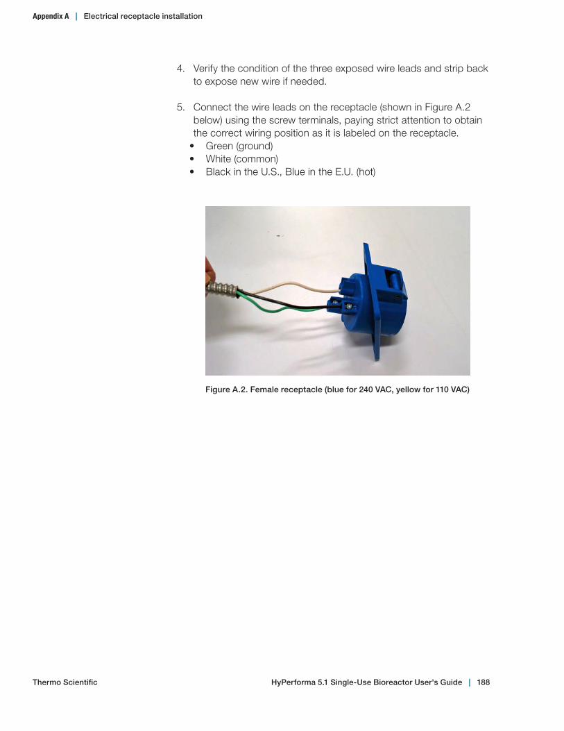
4. Verify the condition of the three exposed wire leads and strip back to expose new wire if needed.
5. Connect the wire leads on the receptacle (shown in Figure A.2 below) using the screw terminals, paying strict attention to obtain the correct wiring position as it is labeled on the receptacle.
• Green (ground)• White (common)• Black in the U.S., Blue in the E.U. (hot)
Figure A.2. Female receptacle (blue for 240 VAC, yellow for 110 VAC)
Appendix A | Electrical receptacle installation
Thermo Scientific HyPerforma 5.1 Single‑Use Bioreactor User's Guide | 188
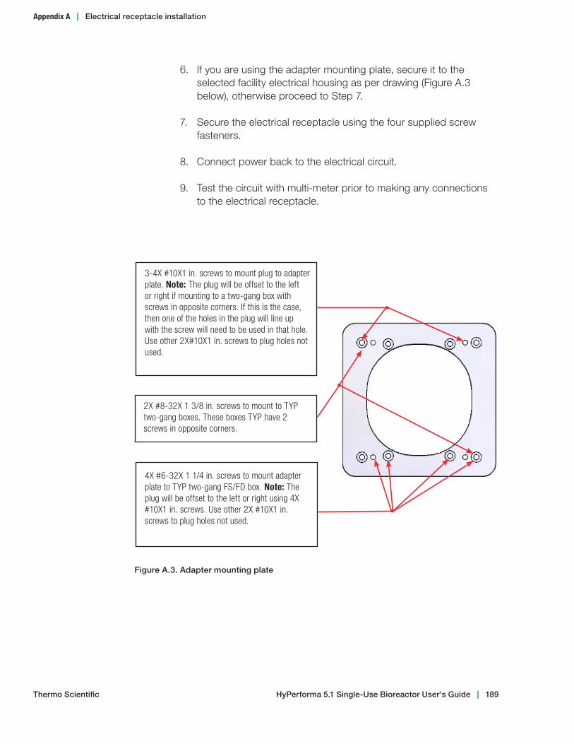
6. If you are using the adapter mounting plate, secure it to the selected facility electrical housing as per drawing (Figure A.3 below), otherwise proceed to Step 7.
7. Secure the electrical receptacle using the four supplied screw fasteners.
8. Connect power back to the electrical circuit.
9. Test the circuit with multi-meter prior to making any connections to the electrical receptacle.
3-4X #10X1 in. screws to mount plug to adapter plate. Note: The plug will be offset to the left or right if mounting to a two-gang box with screws in opposite corners. If this is the case, then one of the holes in the plug will line up with the screw will need to be used in that hole. Use other 2X#10X1 in. screws to plug holes not used.
2X #8-32X 1 3/8 in. screws to mount to TYP two-gang boxes. These boxes TYP have 2 screws in opposite corners.
4X #6-32X 1 1/4 in. screws to mount adapter plate to TYP two-gang FS/FD box. Note: The plug will be offset to the left or right using 4X #10X1 in. screws. Use other 2X #10X1 in. screws to plug holes not used.
Figure A.3. Adapter mounting plate
Appendix A | Electrical receptacle installation
Thermo Scientific HyPerforma 5.1 Single‑Use Bioreactor User's Guide | 189
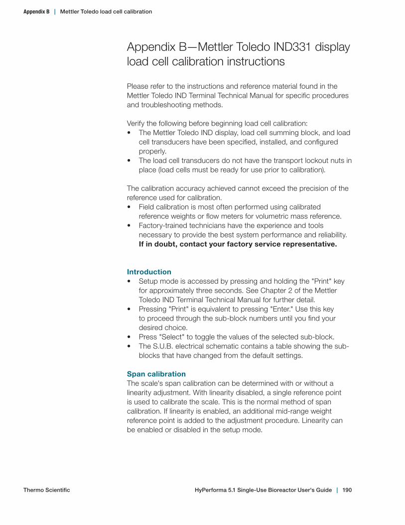
Appendix B—Mettler Toledo IND331 display load cell calibration instructions
Please refer to the instructions and reference material found in the Mettler Toledo IND Terminal Technical Manual for specific procedures and troubleshooting methods.
Verify the following before beginning load cell calibration:• The Mettler Toledo IND display, load cell summing block, and load
cell transducers have been specified, installed, and configured properly.
• The load cell transducers do not have the transport lockout nuts in place (load cells must be ready for use prior to calibration).
The calibration accuracy achieved cannot exceed the precision of the reference used for calibration.• Field calibration is most often performed using calibrated
reference weights or flow meters for volumetric mass reference.• Factory-trained technicians have the experience and tools
necessary to provide the best system performance and reliability. If in doubt, contact your factory service representative.
Introduction• Setup mode is accessed by pressing and holding the "Print" key
for approximately three seconds. See Chapter 2 of the Mettler Toledo IND Terminal Technical Manual for further detail.
• Pressing "Print" is equivalent to pressing "Enter." Use this key to proceed through the sub-block numbers until you find your desired choice.
• Press "Select" to toggle the values of the selected sub-block.• The S.U.B. electrical schematic contains a table showing the sub-
blocks that have changed from the default settings.
Span calibrationThe scale's span calibration can be determined with or without a linearity adjustment. With linearity disabled, a single reference point is used to calibrate the scale. This is the normal method of span calibration. If linearity is enabled, an additional mid-range weight reference point is added to the adjustment procedure. Linearity can be enabled or disabled in the setup mode.
Appendix B | Mettler Toledo load cell calibration
Thermo Scientific HyPerforma 5.1 Single‑Use Bioreactor User's Guide | 190
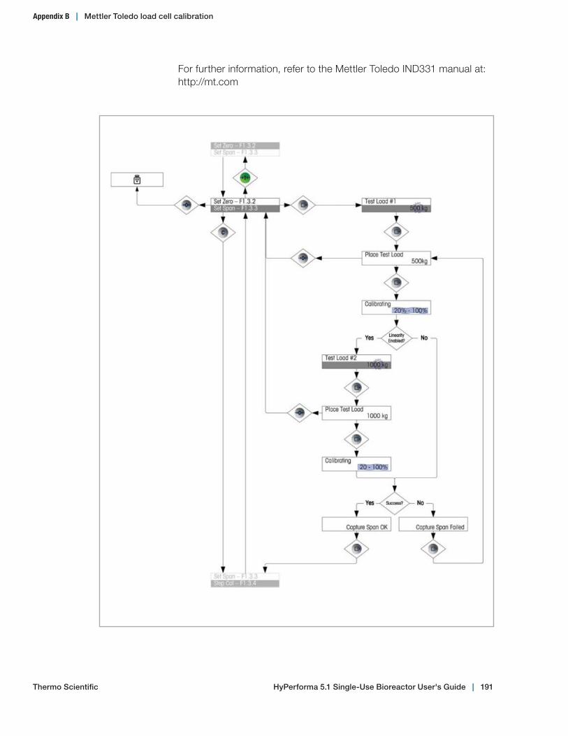
For further information, refer to the Mettler Toledo IND331 manual at: http://mt.com
Appendix B | Mettler Toledo load cell calibration
Thermo Scientific HyPerforma 5.1 Single‑Use Bioreactor User's Guide | 191
Appendix C—2,000 L S.U.B. agitator operation and maintenance guidelines
2,000 L Critical operating recommendations
WARNING: To prevent drive shaft breakage and maintain the equipment warranty, follow the operating recommendations listed below.
9 Verify that the motor variable frequency drive (VFD) is programmed to accelerate and decelerate in a minimum of 60 seconds.
9 Use a controller agitation speed governor and safety interlocks to prevent the system from running outside of recommended limits.
9 Verify that the drive shaft serial numbers match on all segments; do not interchange shaft segments.
9 Always maintain a log history of drive shaft usage (see Appendix D) and confirm that it has sufficient life remaining. If the age or history of a shaft is questionable, it should be replaced. For more information, see Maintenance in section 5.1 of this publication.
9 Only activate agitation after the BPC has been filled with media. 9 Use at least three operators to load the BPC into the 2,000 L
S.U.B. 9 Fully inflate the BPC prior to insertion of the drive shaft. This will
keep the impeller tubing from stretching and being damaged.
Agitation speed recommendationsTable 3.3 in section 3.6.4 of this guide provides agitation speed recommendations for all system sizes. 2,000 L bioreactor recommendations are for systems with four-piece drive shafts, but two-piece shafts will provide equivalent or greater longevity.
Note: The nominal agitation recommendations in Table 3.3 are based on P/V values of 20 W/m3. This is the suggested default parameter for CHO cultivation. For more information on P/V calculation, see section 3.6.5 of this user's guide.
Appendix C | 2,000 L agitator operation and maintenance guidelines
Thermo Scientific HyPerforma 5.1 Single‑Use Bioreactor User's Guide | 192

Appendix D—Drive shaft use log
A sample log is provided below for tracking and documenting drive shaft usage. Important note: For warranty purposes, users must document proper drive shaft use.
Drive shaft serial number:
Vessel serial number:
Start date Agitation setting (start)
Agitation setting (stop)
Starting volume
Finishingvolume End date Number of days
Cumulative run time:
Appendix D | Drive shaft use log
Thermo Scientific HyPerforma 5.1 Single‑Use Bioreactor User's Guide | 193

HyPerforma 5.1 Single‑Use Bioreactor User's Guide | 194Thermo Scientific
Appendix E | Application enhancements for the HyPerforma S.U.B.
Appendix E—Application enhancements for the HyPerforma S.U.B.
While the legacy and 5.1 S.U.B. designs are effective for most bioprocessing applications, specific applications have required case-by-case, engineered-to-order modifications to the S.U.B. These applications can generally be grouped into the following categories: perfusion, fed-batch, and microcarrier. By standardizing products and requests into each specific category, Thermo Fisher Scientific can better support customer needs and provide a more reliable product.
Table E.1 outlines the application-specific requirements of each design modification. Generally, these applications require higher power input, but have varying needs of mass transfer and turndown ratio. Relying on standard components and staying within the capabilities of existing manufacturing equipment, simple iterations of the S.U.B. have been created to achieve the demands outlined. These application-specific designs are described in the following sections, showing how each S.U.B. can be configured to meet the individual process demands.
Table E.1. Application‑specific needs for Enhanced S.U.B.s.
Perfusion Fed-batch Microcarrier
Mixing power Higher Higher Higher
Tip speed N/A N/A Lower
Mass transfer Higher Higher N/A
Turndown ratio N/A High High
Specific porting ATF/TFF N/A Media exchange
Enhanced S.U.B. for perfusionRecently, perfusion cell culture, wherein cells are grown to high cell densities and maintained for long durations by utilizing a cell separator and constant media exchanges, has played a major role in advancing the concept of continuous processing. While standard S.U.B.s have been shown to sustain growth at relatively low perfusion demand, some customers have desired to increase mass transfer and mixing to higher levels. This has led some users to drive the system to its performance limits while operating far above the recommended gassing and agitation limits of the systems. Therefore, further enhancements to the legacy S.U.B. were needed to achieve the performance required by these high-demand cultures.
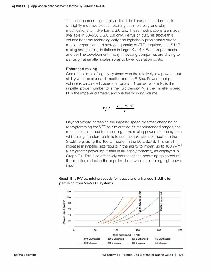
HyPerforma 5.1 Single‑Use Bioreactor User's Guide | 195Thermo Scientific
Graph E.1. P/V vs. mixing speeds for legacy and enhanced S.U.B.s for perfusion from 50–500 L systems.
Appendix E | Application enhancements for the HyPerforma S.U.B.
The enhancements generally utilized the library of standard parts or slightly modified pieces, resulting in simple plug-and-play modifications to HyPerforma S.U.B.s. These modifications are made available in 50–500 L S.U.B.s only. Perfusion cultures above this volume become technologically and logistically problematic due to media preparation and storage, quantity of ATFs required, and S.U.B. mixing and gassing limitations in larger S.U.B.s. With proper media and cell line development, many innovating companies are driving to perfusion at smaller scales so as to lower operation costs.
Enhanced mixingOne of the limits of legacy systems was the relatively low power input ability with the standard impeller and the E-Box. Power input per volume is calculated based on Equation 1 below, where NP is the impeller power number, ρ is the fluid density, Ni is the impeller speed, Di is the impeller diameter, and v is the working volume.
Beyond simply increasing the impeller speed by either changing or reprogramming the VFD to run outside its recommended ranges, the most logical method for imparting more mixing power into the system while using standard parts is to use the next size up impeller in the S.U.B., e.g. using the 100 L impeller in the 50 L S.U.B. This small increase in impeller size results in the ability to impart up to 100 W/m3 (2.5x greater power input than in all legacy systems), as displayed in Graph E.1. This also effectively decreases the operating tip speed of the impeller, reducing the impeller shear while maintaining high power input.
HyPerforma 5.1 Single‑Use Bioreactor User's Guide | 196Thermo Scientific
Appendix E | Application enhancements for the HyPerforma S.U.B.
The challenge of increasing impeller size is avoiding impeller interference on the S.U.B. BPC and hardware while maintaining sufficient mixing capabilities and increasing mass transfer capabilities. It was found that using standard 2.1 drive shafts and 16.5° motor mounting hardware resulted in the impeller being positioned above the sparger and sufficiently away from the BPC wall to avoid any possible damage.
Enhanced spargingSubstantial increases in mass transfer were obtained by not only increasing agitation, but also by altering the sparging system in the S.U.B. Bubble sizes were reduced by reducing the DHS pore size in all S.U.B.s, effectively increasing the surface area of mass transfer. At the same time, DHS pore quantities were increased to maximize the gas flux area, allowing flow rates of up to 0.1–0.2 vvm while maintaining gas entrance velocities at or below 23 m/s.
While frit spargers can be included in perfusion processes, experience has shown that high cell densities and protein concentrations obtained in perfusion processes often lead to fouling of the frit surface. Buildup of this cell material can lead to large deviations in mass transfer performance, and eventually to a near total loss in performance. While slight fouling of the DHS pores may occur, no effective loss in mass transfer has been observed. For this reason, it is recommended to use the DHS in all perfusion applications.
Perfusion‑specific BPC modificationsIn order to accommodate perfusion at all scales, ports for either alternating tangential flow (ATF) or tangential flow filtration (TFF) are included on standard drawings. For ATF connections, these generally include one or two large 1 in. ports and a length of thick-wall C-Flex tubing, terminating in a 1 in. CPC AseptiQuik X sterile connector. This makes for a simple and reliable connection to either an ATF6 or ATF10 filter. For TFF connections, port and tubing size are built per vessel size, minimizing tubing length and hold-up volume. These connections terminate in CPC AseptiQuik G connectors in standard drawings. As with most parts on standard drawings, these can be changed to fit customer needs.
Also included as a means of achieving target cell densities during perfusion processes is a dedicated bleed port for pulling cells from the culture. Often these reactor bleeds are performed when cells grow past target cell densities, and can be controlled either via cell density sensors or mathematically determining bleed rates based on target cell densities and cell growth rates.
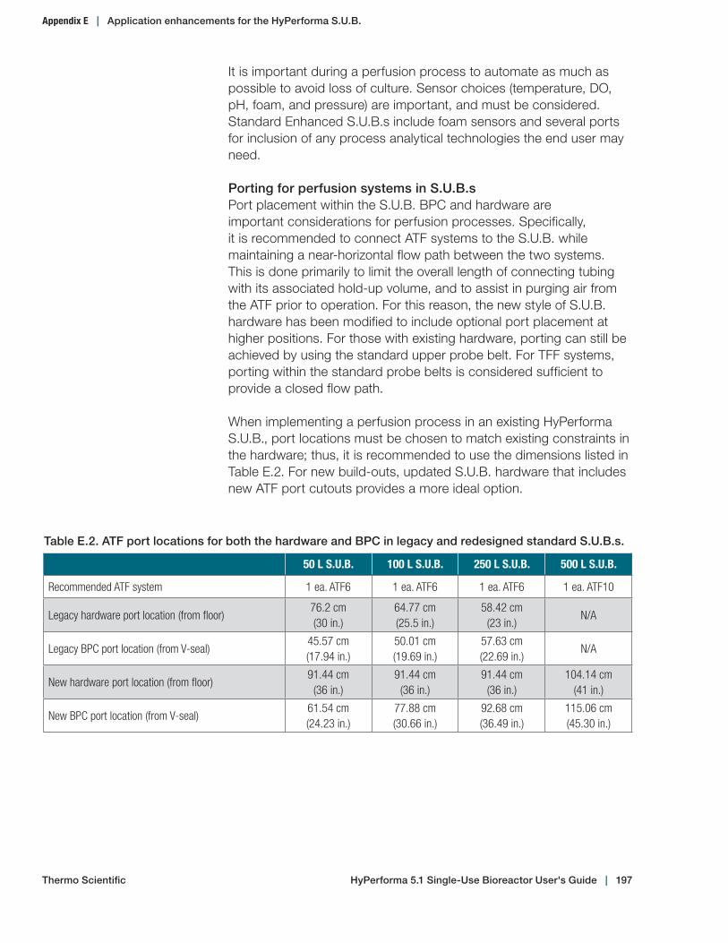
HyPerforma 5.1 Single‑Use Bioreactor User's Guide | 197Thermo Scientific
Appendix E | Application enhancements for the HyPerforma S.U.B.
It is important during a perfusion process to automate as much as possible to avoid loss of culture. Sensor choices (temperature, DO, pH, foam, and pressure) are important, and must be considered. Standard Enhanced S.U.B.s include foam sensors and several ports for inclusion of any process analytical technologies the end user may need.
Porting for perfusion systems in S.U.B.sPort placement within the S.U.B. BPC and hardware are important considerations for perfusion processes. Specifically, it is recommended to connect ATF systems to the S.U.B. while maintaining a near-horizontal flow path between the two systems. This is done primarily to limit the overall length of connecting tubing with its associated hold-up volume, and to assist in purging air from the ATF prior to operation. For this reason, the new style of S.U.B. hardware has been modified to include optional port placement at higher positions. For those with existing hardware, porting can still be achieved by using the standard upper probe belt. For TFF systems, porting within the standard probe belts is considered sufficient to provide a closed flow path.
When implementing a perfusion process in an existing HyPerforma S.U.B., port locations must be chosen to match existing constraints in the hardware; thus, it is recommended to use the dimensions listed in Table E.2. For new build-outs, updated S.U.B. hardware that includes new ATF port cutouts provides a more ideal option.
Table E.2. ATF port locations for both the hardware and BPC in legacy and redesigned standard S.U.B.s.
50 L S.U.B. 100 L S.U.B. 250 L S.U.B. 500 L S.U.B.
Recommended ATF system 1 ea. ATF6 1 ea. ATF6 1 ea. ATF6 1 ea. ATF10
Legacy hardware port location (from floor)76.2 cm (30 in.)
64.77 cm (25.5 in.)
58.42 cm (23 in.)
N/A
Legacy BPC port location (from V-seal)45.57 cm (17.94 in.)
50.01 cm (19.69 in.)
57.63 cm (22.69 in.)
N/A
New hardware port location (from floor)91.44 cm
(36 in.)91.44 cm
(36 in.)91.44 cm
(36 in.)104.14 cm
(41 in.)
New BPC port location (from V-seal)61.54 cm (24.23 in.)
77.88 cm (30.66 in.)
92.68 cm (36.49 in.)
115.06 cm (45.30 in.)

HyPerforma 5.1 Single‑Use Bioreactor User's Guide | 198Thermo Scientific
Appendix E | Application enhancements for the HyPerforma S.U.B.
Enhanced S.U.B. for fed-batchThe Enhanced S.U.B. for fed-batch was configured based on a combination of 5.1 and perfusion designs. To achieve higher mixing input, the larger impeller used in the perfusion application was implemented, allowing power input up to 100 W/m3. At the same time, the requirement of lower turndown ratio for lower seed volume, and mixing through drain with the larger impeller required a redesign of the impeller drive shaft to maintain a minimal impeller clearance from the bottom of the S.U.B. Because the new impeller is slightly larger than the legacy configuration, the impeller isn't fully covered by liquid below a 4:1 volume (e.g. 12.5 L in a 50 L S.U.B.). Figure E.1 depicts the impeller position within the 500 L S.U.B. for each design iteration.
Similar to the Enhanced S.U.B. for perfusion, the fed-batch version required higher mass transfer. The same DHS is used to achieve gas flow rates up to 0.1–0.2 vvm while maintaining minimal gas entrance velocity. However, due to the impeller position in the fed-batch S.U.B., gas dispersion and mixing at full volume are less effective, providing slightly lower kLa in the fed-batch S.U.B. compared to the perfusion design.
Due to the closer proximity of the larger impeller to the front of the vessel, especially in the cases of the 50 L and 100 L Enhanced S.U.B.s, the shorter temperature well (SV21487.02) is implemented for temperature control. This also requires changing the RTD for the controller to the shorter version (SV50999.04) to allow locking the RTD to the temperature well through the luer lock connection. For consistency, this combination of components has been implemented in all versions of the Enhanced S.U.B.
Figure E.1. 500 L S.U.B. versions, including 2.1 legacy, 5.1, enhanced S.U.B. for perfusion, fed‑batch, and microcarrier.
HyPerforma 5.1 Single‑Use Bioreactor User's Guide | 199Thermo Scientific
Appendix E | Application enhancements for the HyPerforma S.U.B.
Enhanced S.U.B. for microcarrierWhile adherent cell cultures in standard S.U.B.s with microcarriers have been demonstrated, they represent a much smaller percentage of use than their suspension counterparts. Increased applications requiring adherent cell cultures and a shift from traditional systems to single-use are the impetus for enhancing the S.U.B. directly for microcarrier culture applications. The flexibility of S.U.B.s, as well as the fact that all moving drive parts are located outside of culture liquid, lend to successful microcarrier cultures where particles or beads will not be compromised. As before, the enhancements utilized the library of standard parts or slightly modified pieces for simple modifications to HyPerforma S.U.B.s ranging from 50 to 500 L in volume. While work above this volume may be possible, those enhancements would be evaluated on a case-by-case basis to ensure optimal performance.
Enhanced mixingIn microcarrier-based cultures, settling of adherent cells on beads at the bottom of the vessel is a key concern. Cells in such a state will experience hypoxia and dramatic pH deviations from the bulk culture. The implementation of a larger size impeller provides greater power input per rotation, as explained above. This allows for overall reductions in operating rotational speeds while providing sufficient lift and bottom sweeping from the down-pumping impeller to prevent settling of particles. This decreased operation speed is key for maintaining low shear rates of the impeller, as well as preserving impeller-related Kolmogorov lengths above 1/2–2/3 the diameter of the microcarrier particles (see Equation 2 below). By thus preventing small eddy lengths and impeller tip speeds (Equation 3), cells are less likely to be sheared off of the microcarriers.
In the above equations, λ is the Kolmogorov length, µ is the fluid kinematic viscosity, ρ is the fluid density, NP is the impeller power number, Di is the impeller diameter, Ni is the impeller speed, and utip is the impeller tip speed.
The effects of these impeller modifications can be seen in Graphs E.2 and E.3, depicting Kolmogorov lengths and tip speeds with respect to power input. At equivalent Kolmogorov length, higher power and lower tip speed is achievable when utilizing a larger impeller.
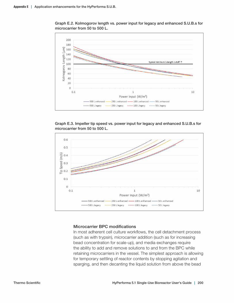
HyPerforma 5.1 Single‑Use Bioreactor User's Guide | 200Thermo Scientific
Graph E.2. Kolmogorov length vs. power input for legacy and enhanced S.U.B.s for microcarrier from 50 to 500 L.
Appendix E | Application enhancements for the HyPerforma S.U.B.
Graph E.3. Impeller tip speed vs. power input for legacy and enhanced S.U.B.s for microcarrier from 50 to 500 L.
Microcarrier BPC modificationsIn most adherent cell culture workflows, the cell detachment process (such as with trypsin), microcarrier addition (such as for increasing bead concentration for scale-up), and media exchanges require the ability to add and remove solutions to and from the BPC while retaining microcarriers in the vessel. The simplest approach is allowing for temporary settling of reactor contents by stopping agitation and sparging, and then decanting the liquid solution from above the bead
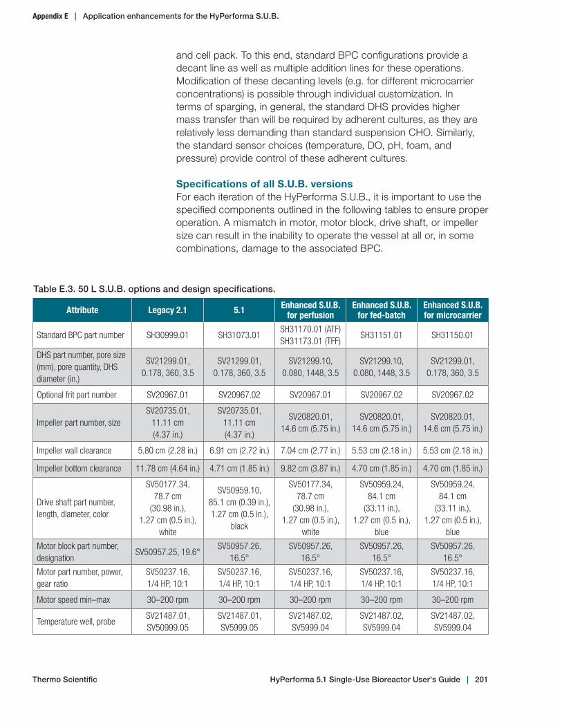
HyPerforma 5.1 Single‑Use Bioreactor User's Guide | 201Thermo Scientific
Appendix E | Application enhancements for the HyPerforma S.U.B.
and cell pack. To this end, standard BPC configurations provide a decant line as well as multiple addition lines for these operations. Modification of these decanting levels (e.g. for different microcarrier concentrations) is possible through individual customization. In terms of sparging, in general, the standard DHS provides higher mass transfer than will be required by adherent cultures, as they are relatively less demanding than standard suspension CHO. Similarly, the standard sensor choices (temperature, DO, pH, foam, and pressure) provide control of these adherent cultures.
Specifications of all S.U.B. versionsFor each iteration of the HyPerforma S.U.B., it is important to use the specified components outlined in the following tables to ensure proper operation. A mismatch in motor, motor block, drive shaft, or impeller size can result in the inability to operate the vessel at all or, in some combinations, damage to the associated BPC.
Table E.3. 50 L S.U.B. options and design specifications.
Attribute Legacy 2.1 5.1 Enhanced S.U.B. for perfusion
Enhanced S.U.B. for fed-batch
Enhanced S.U.B. for microcarrier
Standard BPC part number SH30999.01 SH31073.01SH31170.01 (ATF)SH31173.01 (TFF)
SH31151.01 SH31150.01
DHS part number, pore size (mm), pore quantity, DHS diameter (in.)
SV21299.01, 0.178, 360, 3.5
SV21299.01, 0.178, 360, 3.5
SV21299.10, 0.080, 1448, 3.5
SV21299.10, 0.080, 1448, 3.5
SV21299.01, 0.178, 360, 3.5
Optional frit part number SV20967.01 SV20967.02 SV20967.01 SV20967.02 SV20967.02
Impeller part number, sizeSV20735.01,
11.11 cm (4.37 in.)
SV20735.01, 11.11 cm (4.37 in.)
SV20820.01, 14.6 cm (5.75 in.)
SV20820.01, 14.6 cm (5.75 in.)
SV20820.01, 14.6 cm (5.75 in.)
Impeller wall clearance 5.80 cm (2.28 in.) 6.91 cm (2.72 in.) 7.04 cm (2.77 in.) 5.53 cm (2.18 in.) 5.53 cm (2.18 in.)
Impeller bottom clearance 11.78 cm (4.64 in.) 4.71 cm (1.85 in.) 9.82 cm (3.87 in.) 4.70 cm (1.85 in.) 4.70 cm (1.85 in.)
Drive shaft part number, length, diameter, color
SV50177.34, 78.7 cm
(30.98 in.), 1.27 cm (0.5 in.),
white
SV50959.10, 85.1 cm (0.39 in.), 1.27 cm (0.5 in.),
black
SV50177.34,78.7 cm
(30.98 in.),1.27 cm (0.5 in.),
white
SV50959.24,84.1 cm
(33.11 in.), 1.27 cm (0.5 in.),
blue
SV50959.24, 84.1 cm
(33.11 in.), 1.27 cm (0.5 in.),
blue
Motor block part number, designation
SV50957.25, 19.6°SV50957.26,
16.5°SV50957.26,
16.5°SV50957.26,
16.5°SV50957.26,
16.5°
Motor part number, power, gear ratio
SV50237.16,1/4 HP, 10:1
SV50237.16,1/4 HP, 10:1
SV50237.16,1/4 HP, 10:1
SV50237.16,1/4 HP, 10:1
SV50237.16,1/4 HP, 10:1
Motor speed min–max 30–200 rpm 30–200 rpm 30–200 rpm 30–200 rpm 30–200 rpm
Temperature well, probeSV21487.01,SV50999.05
SV21487.01,SV5999.05
SV21487.02,SV5999.04
SV21487.02,SV5999.04
SV21487.02,SV5999.04
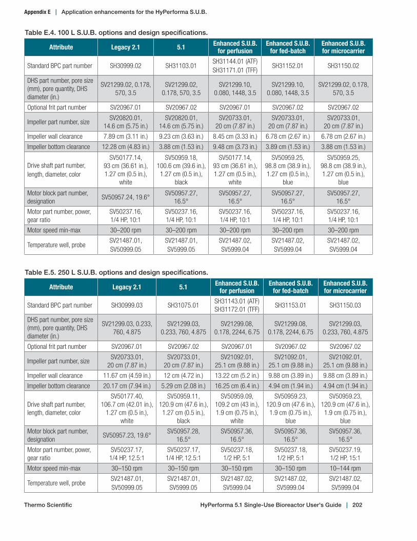
HyPerforma 5.1 Single‑Use Bioreactor User's Guide | 202Thermo Scientific
Appendix E | Application enhancements for the HyPerforma S.U.B.
Table E.4. 100 L S.U.B. options and design specifications.
Attribute Legacy 2.1 5.1 Enhanced S.U.B. for perfusion
Enhanced S.U.B. for fed-batch
Enhanced S.U.B. for microcarrier
Standard BPC part number SH30999.02 SH31103.01SH31144.01 (ATF)SH31171.01 (TFF)
SH31152.01 SH31150.02
DHS part number, pore size (mm), pore quantity, DHS diameter (in.)
SV21299.02, 0.178, 570, 3.5
SV21299.02, 0.178, 570, 3.5
SV21299.10, 0.080, 1448, 3.5
SV21299.10, 0.080, 1448, 3.5
SV21299.02, 0.178, 570, 3.5
Optional frit part number SV20967.01 SV20967.02 SV20967.01 SV20967.02 SV20967.02
Impeller part number, sizeSV20820.01,
14.6 cm (5.75 in.)SV20820.01,
14.6 cm (5.75 in.)SV20733.01,
20 cm (7.87 in.)SV20733.01,
20 cm (7.87 in.)SV20733.01,
20 cm (7.87 in.)
Impeller wall clearance 7.89 cm (3.11 in.) 9.23 cm (3.63 in.) 8.45 cm (3.33 in.) 6.78 cm (2.67 in.) 6.78 cm (2.67 in.)
Impeller bottom clearance 12.28 cm (4.83 in.) 3.88 cm (1.53 in.) 9.48 cm (3.73 in.) 3.89 cm (1.53 in.) 3.88 cm (1.53 in.)
Drive shaft part number, length, diameter, color
SV50177.14, 93 cm (36.61 in.), 1.27 cm (0.5 in.),
white
SV50959.18, 100.6 cm (39.6 in.),
1.27 cm (0.5 in.), black
SV50177.14,93 cm (36.61 in.),1.27 cm (0.5 in.),
white
SV50959.25,98.8 cm (38.9 in.), 1.27 cm (0.5 in.),
blue
SV50959.25, 98.8 cm (38.9 in.), 1.27 cm (0.5 in.),
blue
Motor block part number, designation
SV50957.24, 19.6°SV50957.27,
16.5°SV50957.27,
16.5°SV50957.27,
16.5°SV50957.27,
16.5°
Motor part number, power, gear ratio
SV50237.16,1/4 HP, 10:1
SV50237.16,1/4 HP, 10:1
SV50237.16,1/4 HP, 10:1
SV50237.16,1/4 HP, 10:1
SV50237.16,1/4 HP, 10:1
Motor speed min-max 30–200 rpm 30–200 rpm 30–200 rpm 30–200 rpm 30–200 rpm
Temperature well, probeSV21487.01,SV50999.05
SV21487.01,SV5999.05
SV21487.02,SV5999.04
SV21487.02,SV5999.04
SV21487.02,SV5999.04
Table E.5. 250 L S.U.B. options and design specifications.
Attribute Legacy 2.1 5.1 Enhanced S.U.B. for perfusion
Enhanced S.U.B. for fed-batch
Enhanced S.U.B. for microcarrier
Standard BPC part number SH30999.03 SH31075.01SH31143.01 (ATF)SH31172.01 (TFF)
SH31153.01 SH31150.03
DHS part number, pore size (mm), pore quantity, DHS diameter (in.)
SV21299.03, 0.233, 760, 4.875
SV21299.03, 0.233, 760, 4.875
SV21299.08, 0.178, 2244, 6.75
SV21299.08, 0.178, 2244, 6.75
SV21299.03, 0.233, 760, 4.875
Optional frit part number SV20967.01 SV20967.02 SV20967.01 SV20967.02 SV20967.02
Impeller part number, sizeSV20733.01,
20 cm (7.87 in.)SV20733.01,
20 cm (7.87 in.)SV21092.01,
25.1 cm (9.88 in.)SV21092.01,
25.1 cm (9.88 in.)SV21092.01,
25.1 cm (9.88 in.)
Impeller wall clearance 11.67 cm (4.59 in.) 12 cm (4.72 in.) 13.22 cm (5.2 in.) 9.88 cm (3.89 in.) 9.88 cm (3.89 in.)
Impeller bottom clearance 20.17 cm (7.94 in.) 5.29 cm (2.08 in.) 16.25 cm (6.4 in.) 4.94 cm (1.94 in.) 4.94 cm (1.94 in.)
Drive shaft part number, length, diameter, color
SV50177.40, 106.7 cm (42.01 in.),
1.27 cm (0.5 in.), white
SV50959.11, 120.9 cm (47.6 in.),
1.27 cm (0.5 in.), black
SV50959.09,109.2 cm (43 in.),1.9 cm (0.75 in.),
white
SV50959.23,120.9 cm (47.6 in.), 1.9 cm (0.75 in.),
blue
SV50959.23, 120.9 cm (47.6 in.), 1.9 cm (0.75 in.),
blue
Motor block part number, designation
SV50957.23, 19.6°SV50957.28,
16.5°SV50957.36,
16.5°SV50957.36,
16.5°SV50957.36,
16.5°
Motor part number, power, gear ratio
SV50237.17,1/4 HP, 12.5:1
SV50237.17,1/4 HP, 12.5:1
SV50237.18,1/2 HP, 5:1
SV50237.18,1/2 HP, 5:1
SV50237.19,1/2 HP, 15:1
Motor speed min-max 30–150 rpm 30–150 rpm 30–150 rpm 30–150 rpm 10–144 rpm
Temperature well, probeSV21487.01,SV50999.05
SV21487.01,SV5999.05
SV21487.02,SV5999.04
SV21487.02,SV5999.04
SV21487.02,SV5999.04
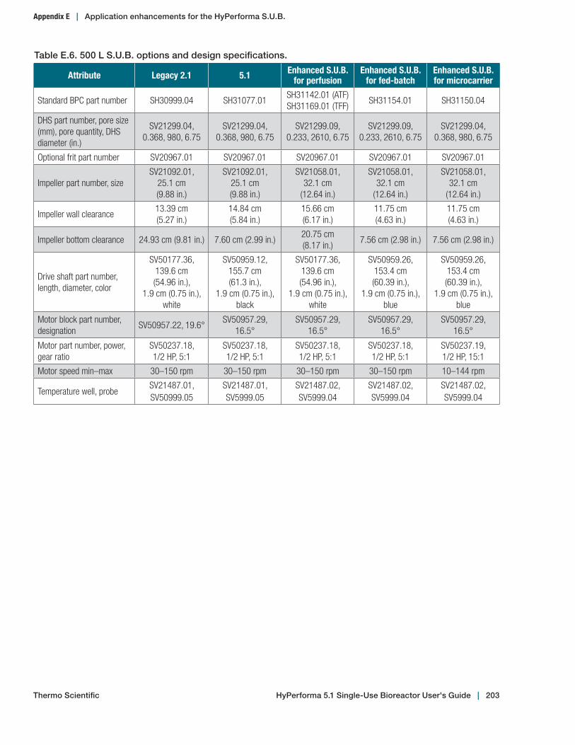
HyPerforma 5.1 Single‑Use Bioreactor User's Guide | 203
Appendix E | Application enhancements for the HyPerforma S.U.B.
Table E.6. 500 L S.U.B. options and design specifications.
Attribute Legacy 2.1 5.1 Enhanced S.U.B. for perfusion
Enhanced S.U.B. for fed-batch
Enhanced S.U.B. for microcarrier
Standard BPC part number SH30999.04 SH31077.01SH31142.01 (ATF)SH31169.01 (TFF)
SH31154.01 SH31150.04
DHS part number, pore size (mm), pore quantity, DHS diameter (in.)
SV21299.04, 0.368, 980, 6.75
SV21299.04, 0.368, 980, 6.75
SV21299.09, 0.233, 2610, 6.75
SV21299.09,0.233, 2610, 6.75
SV21299.04, 0.368, 980, 6.75
Optional frit part number SV20967.01 SV20967.01 SV20967.01 SV20967.01 SV20967.01
Impeller part number, sizeSV21092.01,
25.1 cm (9.88 in.)
SV21092.01, 25.1 cm (9.88 in.)
SV21058.01, 32.1 cm
(12.64 in.)
SV21058.01, 32.1 cm
(12.64 in.)
SV21058.01, 32.1 cm
(12.64 in.)
Impeller wall clearance13.39 cm (5.27 in.)
14.84 cm (5.84 in.)
15.66 cm (6.17 in.)
11.75 cm (4.63 in.)
11.75 cm (4.63 in.)
Impeller bottom clearance 24.93 cm (9.81 in.) 7.60 cm (2.99 in.)20.75 cm (8.17 in.)
7.56 cm (2.98 in.) 7.56 cm (2.98 in.)
Drive shaft part number, length, diameter, color
SV50177.36, 139.6 cm (54.96 in.),
1.9 cm (0.75 in.), white
SV50959.12, 155.7 cm (61.3 in.),
1.9 cm (0.75 in.), black
SV50177.36,139.6 cm (54.96 in.),
1.9 cm (0.75 in.), white
SV50959.26,153.4 cm (60.39 in.),
1.9 cm (0.75 in.), blue
SV50959.26,153.4 cm (60.39 in.),
1.9 cm (0.75 in.), blue
Motor block part number, designation
SV50957.22, 19.6°SV50957.29,
16.5°SV50957.29,
16.5°SV50957.29,
16.5°SV50957.29,
16.5°
Motor part number, power, gear ratio
SV50237.18,1/2 HP, 5:1
SV50237.18,1/2 HP, 5:1
SV50237.18,1/2 HP, 5:1
SV50237.18,1/2 HP, 5:1
SV50237.19,1/2 HP, 15:1
Motor speed min–max 30–150 rpm 30–150 rpm 30–150 rpm 30–150 rpm 10–144 rpm
Temperature well, probeSV21487.01,SV50999.05
SV21487.01,SV5999.05
SV21487.02,SV5999.04
SV21487.02,SV5999.04
SV21487.02,SV5999.04
Thermo Scientific

Find out more at thermofisher.com/subFor Research or Further Manufacturing. Not for diagnostic use or direct administration into humans or animals.© 2018 Thermo Fisher Scientific Inc. All rights reserved. All trademarks are the property of Thermo Fisher Scientific and its subsidiaries
unless otherwise specified. Mettler Toledo is a trademark of Mettler Toledo AG. CPC and AseptiQuik are trademarks of Colder Products
Company. SmartSite is a trademark of Becton, Dickinson and Company. C-Flex is a trademark of Saint-Gobain Performance Plastics. AC-
Tech is a trademark of Lenze. Emflon and Kleenpak are trademarks of Pall Corporation. Meissner, Ultracap, and Steridyne are trademarks
of Meissner Filtration Products. SterilEnz is a trademark of PAW BioScience. Teflon is a trademark of The Chemours Company. Velcro
is a trademark of Velcro Company. Instron is a trademark of Illinois Tool Works, Inc. Pluronic and Sigma-Aldrich are trademarks of
MilliporeSigma. DOC0022 Version E