thermo-mechanical analysis of a lever … · the shape of impressions for longitudinal rolling of...
TRANSCRIPT

A R C H I V E S O F M E T A L L U R G Y A N D M A T E R I A L S
Volume 57 2012 Issue 4
DOI: 10.2478/v10172-012-0135-z
J. TOMCZAK∗, Z. PATER∗, T. BULZAK∗
THERMO-MECHANICAL ANALYSIS OF A LEVER PREFORM FORMING FROM MAGNESIUM ALLOY AZ31
TERMOMECHANICZNA ANALIZA KSZTAŁTOWANIA PRZEDKUWKI DŹWIGNI ZE STOPU MAGNEZU AZ31
This paper presents the results of numerical analysis of metal forming process of a lever preform from magnesium alloyAZ31, which will be used as a semi-finished product in the forging process of a lever part. Presently, the lever forging isformed from semi-finished product in the form of a bar, which is connected with large material losses. Numerical simulationswere made for two different metal forming methods: forging longitudinal rolling and cross-wedge rolling. Calculations wereconducted basing on finite element method (FEM), applying commercial software DEFORM-3D. Geometrical models usedin calculations were discussed. Simulations, made in conditions of three dimensional state of strain, allowed for determiningdistributions of strain intensity, temperature, cracking criterion, and mainly for determining the possibility of a lever preformmanufacturing on the basis of rolling processes. Considering the obtained results of numerical simulations, the design of toolsfor semi-finished products rolling was worked out; these semi-finished products will be used for experimental verification ofthe lever preforms forming.
Keywords: cross-wedge rolling, longitudinal forging process, preform, FEM, magnesium alloy AZ31
W artykule przedstawiono wyniki analizy numerycznej procesu kształtowania plastycznego przedkuwki dźwigni ze stopumagnezu AZ31, która posłuży jako półfabrykat w procesie kucia odkuwki dźwigni. Obecnie odkuwkę dźwigni kształtuje sięz półfabrykatu w kształcie pręta, co związane jest z dużymi stratami materiałowymi. Symulacje numeryczne wykonano dladwóch różnych metod kształtowania plastycznego: kuźniczego walcowania wzdłużnego oraz walcowania poprzeczno-klinowego.Obliczenia przeprowadzono w oparciu o metodę elementów skończonych (MES), wykorzystując komercyjny pakiet oprogramo-wania DEFORM-3D. Omówiono modele geometryczne zastosowane w obliczeniach. Symulacje przeprowadzone w warunkachprzestrzennego stanu odkształcenia umożliwiły wyznaczenie rozkładów intensywności odkształcenia, temperatury, kryteriumpękania, a przede wszystkim określenie możliwości wytwarzania przedkuwki dźwigni w oparciu o procesy walcownicze.W oparciu o uzyskane wyniki symulacji numerycznych opracowano konstrukcję narzędzi do walcowania półfabrykatów, któreposłużą do weryfikacji doświadczalnej kształtowania przedkuwki dźwigni.
1. Introduction
The aim to lower material consumption and con-struction weight at the improvement of exploitation pa-rameters at the same time is a widely spread tendency,observed in the world industry. It is well visible in thecase of elements applied in automotive and aviation in-dustry, where lowering of vehicles and flying machinesweight allows for increasing their technical possibilities(power, speed, capacity, maneuverability, etc.) and lower-ing exploitation costs at the same time. One of the waysof construction mass lowering is the application of high-ly resistant materials, characterized by relatively smalldensity. They include, for example, light metal alloys(aluminum, titanium and magnesium). These materials
are characterized by favorable design parameters – highrelation of resistance to specific gravity, which is consid-erably larger than for steel [1, 2]. However, apart fromnumerous advantages metals alloys (especially magne-sium and titanium) are rarely applied. This results froma high price of these materials and large difficulties dur-ing their forming and machining. Hence, an importantissue becomes the application of manufacturing tech-niques which will allow for reduction of materials andenergy consumption. One of such methods, which, apartfrom reduction of material consumption, allows for in-crease of elements resistance properties is metal formingtechnology.
Within the scope of conducted research-implementa-tion works of metal forming of light metals alloys ap-
∗ LUBLIN UNIVERSITY OF TECHNOLOGY, 20-618 LUBLIN, 36 NADBYSTRZYCKA STR., POLAND
1212
plied in aviation constructions, die forging process of alever forging from magnesium alloy AZ31 was workedout at Lublin University of Technology (Fig. 1) [3].This type of element has been manufactured so far fromaluminum alloys in machining processes. However, afterthe conducted analysis of working conditions and stateof lever load, works were conducted which aimed atchanging of forming technology (into metal formingprocesses) and material type into magnesium alloy (al-most 40% lighter than aluminum alloy). The worked outforging process of lever forging (implemented in one ofthe domestic forging plants) is realized on hammer froma semi-finished product in the form of a bar and allowsfor reducing material consumption and labour of about30%. The further savings can be searched in limitingof technological allowance (flash) due to more optimalmaterial usage. In the result, die forging process of thelever forging on the press from a semi-finished productinitially formed – rolled perform was worked out. Inthis way the number of forging operations was loweredand material consumption was reduced of over 65% incomparison with machining.
Fig. 1. Shape and dimensions of a lever-a and of forming-b madefrom magnesium alloy AZ31
Such a worked out technology was numerically ana-lyzed, simulating the preform forming process, and next,basing on determined semi-finished product shape, thepart forging process was modeled. The process of thelever preform manufacturing was analyzed for two form-ing variants: cross-wedge rolling and forging longitudi-nal rolling. The obtained results of numerical researchworks were used during designing of tools for the leverpreform rolling. The designed tools will be used forexperimental verification of the forming process of thelever preform from magnesium alloy of AZ31 type.
2. Forming processes of lever preform
Die forging processes of longitudinal forgings onpresses require the application of specially formedbillets-preform. The best economical- technical resultsof the forging process, that is high efficiency and qualityof products and the smallest material consumption, areachieved when preforms have the shape close to the forg-ing outline in the parting plane, and particular sections ofthe semi-finished part are equal the sum of appropriatesections of forging and flash [4]. In the result, properlydesigned preform allows for lowering of forming forcein the forging process and increases the die impressiondurability [5].
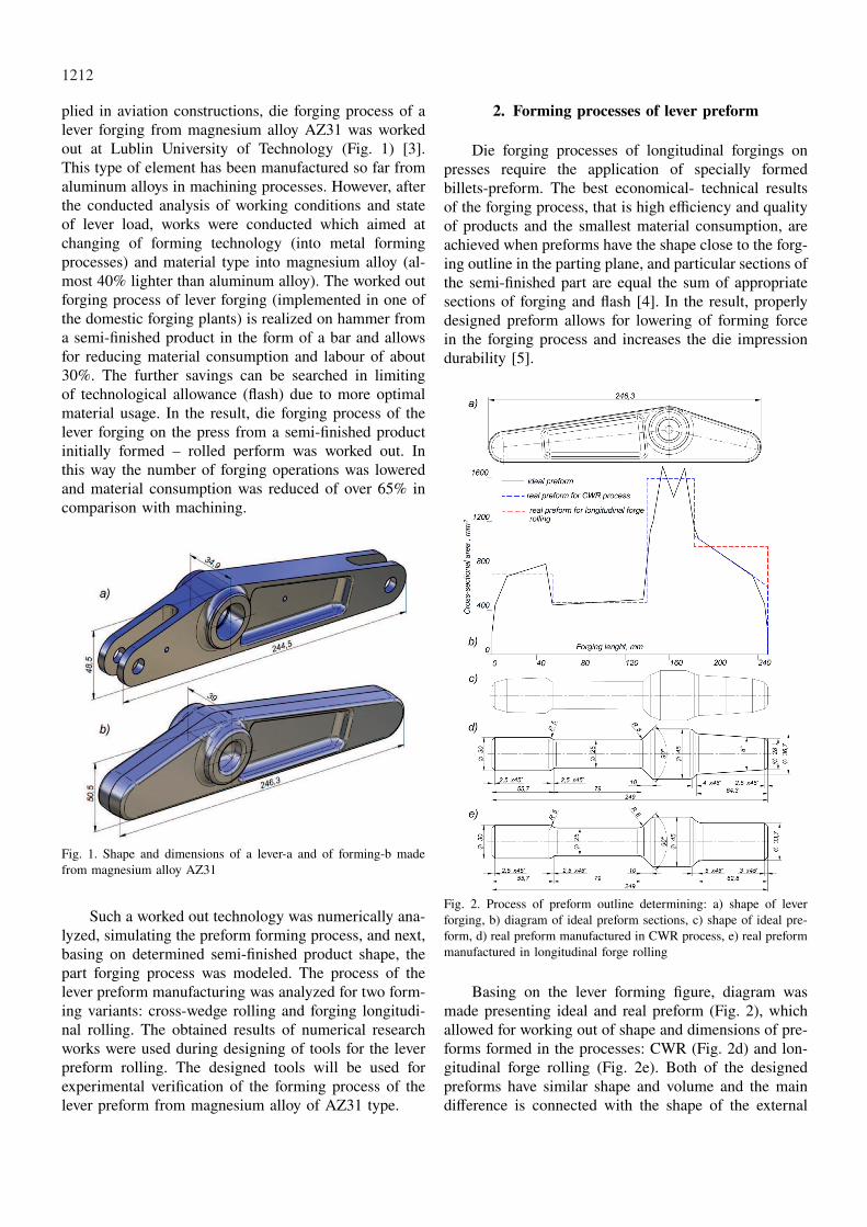
Fig. 2. Process of preform outline determining: a) shape of leverforging, b) diagram of ideal preform sections, c) shape of ideal pre-form, d) real preform manufactured in CWR process, e) real preformmanufactured in longitudinal forge rolling
Basing on the lever forming figure, diagram wasmade presenting ideal and real preform (Fig. 2), whichallowed for working out of shape and dimensions of pre-forms formed in the processes: CWR (Fig. 2d) and lon-gitudinal forge rolling (Fig. 2e). Both of the designedpreforms have similar shape and volume and the maindifference is connected with the shape of the external

1213
pivot. For the semi-finished product rolled in the CWRprocess the pivot has a conical shape, close to the idealpreform outline (Fig. 2c). However, in the preform rolledlongitudinally simplification was used, instead of conicalpivot a cylindrical one was used. This allowed for sim-plification of the preform manufacturing, eliminating thenecessity of designing of impressions with changeablecross section on tools circumference.
Basing on determined preforms shape tools wereworked out allowing for semi-finished products formingin the CWR processes and longitudinal forge rolling.
Fig. 3. Flat-wedge tool segment for CWR of lever preform
Figure 3 presents the shape of a flat-wedge tool seg-ment which was designed for the cross-wedge rollingprocess of lever preform. The semi-finished product isformed in one passage between two plates,which have
wedge protrusions on their surfaces and move in theopposite directions.
The tool working surface consists of four basic ar-eas: initial (cutting), forming, sizing and splitting. Theaim of initial area is forming on the whole circumfer-ence of the billet two ring-shaped grooves of conicalside surfaces. In the forming area, the section reductionis developed on the whole length of the semi-finishedproduct, due to which the further steps of preform areformed. The product shape unevenness, appearing dur-ing rolling, are removed in the sizing area. Yet, sep-aration of external waste (allowance) from the formedsemi-finished product takes place in the splitting area bymeans of cutting knives. In order to increase the stabilityof rolling, at the beginning of the process two guidingpaths were placed in the cutting area. Additionally, on theforming surfaces (in the cutting and forming areas) andon the guiding paths technological notches were made.
The shape of impressions for longitudinal rolling oflever preform is shown in Fig. 4 Considering circularsections of the preform all steps, the system of rollingoval - circle was assumed. The rolling of particular piv-ots was conducted at the following reductions of crosssection Rp (where Rp = (1-(d/do)2)100%, d – the pivotdiameter after rolling in oval and circular impression,do – the diameter before rolling): Rp = 55,5%; Rp =
69%; Rp = 43,5%. Obtaining the required shape anddimensions of external pivots of semi-finished productis realized in two impressions-oval and circular. Yet, thecentral part is rolled in four impressions in the systemof oval – circle – oval – circle.
Fig. 4. Schema presenting forming impressions for particular preformsteps
3. Lever preform forming in the cross-wedge rollingprocess
Cross-wedge rolling process belongs to rotationalmetal forming processes, in which products are formedby means of tools in the shape of wedges. These toolsare mounted on rolling mills or on rolling mills planes.

1214
Cross-wedge rolling processes are characterized by nu-merous advantages in comparison with traditional met-al forming methods [6-8, 12]. The most important in-clude: high efficiency, lower material losses and energyconsumption, high resistance properties of products andrelatively easy process automation. However, from eco-nomical point of view, the CWR technology, especiallyat the application of flat-wedge tools segments, is con-nected with considerably smaller costs connected withtools manufacturing. Hence, the CWR can be success-fully applied in mass production (automotive industry)and at a smaller scale, which is characteristic for theaviation industry.
Estimation of correctness of the worked out technol-ogy was made numerically, simulating the CWR processof lever preform. Calculations were made by meansof finite element method (FEM), using the commercialsoftware DEFORM-3D. For the analysis needs, a geo-metrical model of the cross-wedge rolling process of asemi-finished product was worked out, which is shown inFig. 5. This model consists of two wedge tools, upper – 1and bottom – 2 and of billet – 3. A bar from magnesiumAZ31 of diameter ∅ 44 and length l = 160 mm, modeledby means of hexahedral elements of the first type, wasassumed as billet. The material model of alloy AZ31was determined experimentally in plastometric experi-ments [9]. Billet initial temperature was 400◦C, toolstemperature during rolling became constant and equal100◦C. Flat-wedge tools segments, during the process,moved in the opposite directions with constant velocityv = 0,2 mm/s. Moreover, in calculations was assumedmodel of constant friction, defined by friction factor oflimiting value m = 1 at tool – billet surface of contact,which resulted from lack of lubrication of tools duringthe process. Yet, heat exchange coefficient between ma-terial and tools was assumed at the level 8 kW/m2K,between billet and the environment 0.2 kW/m2K.
Fig. 5. Geometrical model of CWR process of lever preform
In the result of conducted numerical simulationsmetal flow kinematics in the process was analyzed,shown in Fig. 6. At the beginning of the process, wedge
Fig. 6. Lever preform shape progression determined numerically dur-ing CWR simulation with marked strain intensity distribution

1215
protrusions cut into the semi-finished product and put itinto rotary motion. Two ring-shaped grooves are formedat billet circumference, which, at the further stages ofthe process, are widened by tools wedge side surfacesat the assumed rolling length. At the end of the process,external edges constituting technological allowance arecut from the formed preform. Determined numericallyshape of the preform is characterized by large conver-gence with theoretical outline, worked out on the basisof the ideal preform diagram. Due to difficulties of nu-merical character, the process of allowance cutting hasnot been fully finished yet. In real process, realized inlaboratory conditions, allowance will be completely cutoff from the formed semi-finished product.
The next Figure 7 presents distributions ofstrain intensity, temperature and damage (according toCockcroft-Latham criterion), which was determined dur-ing numerical simulations for the final stage of the CWRprocess. It can be seen that the strains (Fig. 7a) reachlarge values. The largest values of strains are localizedin the area of external conical pivot, which can be ex-plained by relatively large unnecessary deformations inthis area, which are the result of material intensive flowin circumferential direction. The rest of the semi-finishedproduct areas undergo smaller deformations, yet the ma-terial is worked plastically in the whole volume, apartfrom external areas which constitute allowance cut at theend of the process.
Fig. 7. Determined in CWR process simulation of lever preform dis-tributions; a) strain intensity, b) temperature, c) damage criterionaccording to Cockcroft-Latham (at the end of rolling)
The temperature distribution (Fig. 7b) is strictly con-nected with the deformations character in the formedsemi-finished product. A characteristic feature is rela-tively high and equal value of the temperature, both atthe surface and in sections of the formed product. Thetemperature of the obtained preform oscillates within thescope of 410-430◦C. This is especially important due tolong time of the process (about 6s) and allows to as-sume that the material even at the end of the processwill remain good plastic properties.
Such large values of temperature are connected withgenerating of large heat amounts during the metal plasticdeformation. It is also crucial that the difference betweenmaximal and minimal value of the temperature is rela-tively small (about 20◦C), which is extremely importantin metal forming processes of light metals alloys. Dur-ing numerical calculations CWR of lever preform, thepossibility of cracks appearance was forecast on the ba-sis of damage criterion according to Cockcroft-Latham(Fig. 7c). The obtained calculations results show that inthe analyzed CWR process the danger of metal crackingappears. The area most exposed to cracking is internalstep of the preform, in which the largest cross sectionreduction takes place. The values of Cockcroft-Lathamintegral in this area exceeds permissible values (about0.7 for light metals alloys), which probably leads to thesemi-finished product cracking.
4. Lever preform forming in longitudinal forgerolling process
Using numerical techniques the correctness of con-sidered design-technological assumptions of the preformlongitudinal rolling process was verified. As it was inthe CWR process, calculations were made basing on fi-nite element method, with the application of softwareDEFORM-3D. For calculations needs six geometricalmodels of the preform rolling process were built (forsix roll passes). The models differed between themselvesonly in type of applied tools (shape and length of im-pressions), depending on which step and its outline wasrolled, and in type of billet, which, for next roll pass-es, were semi-finished products rolled in the former im-pressions. One of the geometrical model (rolling in thefirst roll pass in oval impression) used in calculationsis shown in Fig. 8. This model consists of billet, twotools-segments with made on their circumference im-pressions of oval outline, and guiding ring. Billet for thefirst roll pass was the bar of diameter ∅ 45 mm and lengthl = 132 mm, made from magnesium alloy AZ31, mod-eled by means of hexahedral elements. Material model ofalloy AZ31 was determined experimentally in plastomet-ric research works [9-11]. Billet initial temperature was

1216
420◦C, yet, tools temperature during rolling was constantand equal 150◦C. Upper and bottom segments rotatedwith constant velocity n = 60 rot/min in the oppositedirections, according to markings presented in Fig. 8.
Fig. 8. Geometrical model of longitudinal forge rolling process oflever preform in the first roll pass in oval impression: 1,2-tools seg-ments, 3-semi-finished product, 4-guiding ring
On the tool – semi-finished product surface of con-tact constant friction factor was assumed m = 0.8. Ad-ditionally, heat exchange coefficient between billet andtools was assumed at the level 8 kW/m2K, between billetand the environment 0.2 kW/m2K.
In the result of conducted numerical simulationspreform shapes after each roll pass were determined.The further stages of the preform rolling process arepresented in Fig. 9. The obtained calculations resultsconfirm the rightness of assumed technological and de-sign assumptions during tools designing. The preformdetermined shape is characterized by large convergencewith the shape worked out at the designing stage. Phe-nomena which could disturb the rolling process coursewere not observed.
The obtained preform is free from overlapping,bendings, flash which appears during the impressionoverfilling. Also the impression filling is satisfactory.Hence, it can be stated that the designed impressions willallow, with a large probability, for forming of preformsof assumed parameters.
Fig. 9. Lever preform progression of shape determined numericallyafter each roll pass during simulation of longitudinal rolling processwith marked distribution of strain intensity
The next Figure 10 shows determined numericallydistributions of strain intensity, temperature and crack-ing (according to Cockcroft-Latham) for rolled preformafter the sixth roll pass. It can be seen that in the areasof formed steps the material is worked plastically in thewhole volume.However, the observed deformations arenot homogeneous. The cause of such a distribution isvarious values of reduction ratio, which depended onthe degree of the semi-finished product cross sectionreduction. The largest values of strains are localized inthe areas of the preform smallest diameter (formed infour roll passes). Yet, the preform central step of thelargest diameter during rolling does not undergo defor-mation (its diameter equals billet initial diameter). Thedistribution of temperature (Fig. 10b) is connected with

1217
deformations present during rolling. It can be observedthat the temperature remains at relatively large level (al-though the rolling takes place in six roll passes), withinthe scope of 400◦C – 430◦C.
Fig. 10. Determined numerically during simulations of longitudinalrolling process of lever preform distributions; a) strain intensity,b) temperature, c) damage criterion according to Cockcroft-Latham(after the last roll pass)
The noticed decrease of temperature is of surfacecharacter and is caused by material contact with cool-er tools. In the areas of the largest reduction of crosssection, the increase of temperature above the initialvalue can be observed, which can be explained bychange of plastic deformation work into heat. The valuesof Cockcroft-Latham integral (Fig. 10c) are relativelysmaller in comparison with values noticed in the CWRprocess. Similarly as in the previous process, the largestintegral values concentrate in the area of the step of thesmallest diameter, hence, in the area of the largest plasticdeformations. The range of Cockcroft-Latham criterionmaximal values is small. The largest values are local-ized in the surface areas, which allows to presume thatcracking should not take place in the formed preform. Inthe other areas the values of Cockcroft-Latham criterionare relatively small.
5. Simulation of lever forming process fromsemi-finished product in the shape of preform
The obtained results of numerical simulations oflever preform forming for both rolling processes con-firmed the rightness of technological assumptions. Inthe CWR process as well as in longitudinal rolling itis possible to get preforms of assumed geometrical pa-rameters. However, considering the possibility of inter-
nal cracks presence in the preform formed in the CWRprocess, only the longitudinal rolling process will be ver-ified experimentally. Hence, in order to finally confirmthe rightness of the worked out preform shape, simu-lation of lever forging from the semi-finished productformed in the longitudinal rolling process was made.As it was in the processes realized earlier, calculationswere made by means of finite element method with theapplication of software DEFORM-3D. The process wasrealized in two impressions (bending and die), with pre-serving the same edge conditions. In the first impres-sion bending of the preform takes place, next the bend-ed preform is transferred into the second impression-dieimpression-where finished lever forging part. The billettemperature at the beginning of the process was assumedT = 420◦C. Yet, tools temperature became constant andequal T = 150◦C. Other parameters considered in theanalysis include: friction factor between tools and bil-let m = 0.3, heat exchange coefficient between materialand tools 10 kW/m2K. Determined numerically shapeof the lever forging from magnesium alloy AZ31 fromoptimal longitudinally rolled preform is shown in Fig.11. A characteristic feature is large convergence withthe theoretical outline (Fig. 1b). Faults in the form ofoverlapping or impression infilling were not observedand flash was relatively small.
Fig. 11. Determined numerically shape of lever forging from magne-sium alloy AZ31, forged from preform manufactured in longitudinalforge rolling process

1218
6. Summary
Within the scope of conducted research works, twotechnological processes of lever preform from magne-sium alloy AZ31 were worked out, which were later nu-merically simulated. The first of this process is basedon forming of semi-finished product in the cross-wedgerolling process in one pass. However, the second way oflever preform forming longitudinal forge rolling process-es are used in six passes (impressions).
The obtained results of numerical analysis for bothcases of preforms manufacturing confirmed the rightnessof technological assumptions. In the CWR process andin longitudinal rolling as well it is possible to obtainsemi-finished products of assumed geometrical parame-ters, guaranteeing optimal course of the forging processand high quality of forgings. However, in the CWR ofpreforms, there exists the danger of internal cracks pres-ence during rolling, which disqualifies the semi-finishedproduct as billet for lever part forging. Hence, althoughthe CWR processes have numerous advantages, it wasfinally assumed that the lever preform will be formed inlongitudinal forge rolling.
Basing on numerical simulations results, tools seg-ments construction was worked out for longitudinalrolling of the lever preform. These segments will beused for experimental verification of the semi-finishedproduct forming, which is planned to be conducted atLublin University of Technology.
Acknowledgements
The research has been made as part of Project No.POIG.0101.02-00-015/08 titled “Modern Material Technologies inAerospace Industry” under the Innovative Economy Operational Pro-gramme (IEOP). The research has been co-financed by the EuropeanUnion from the funds of the European Regional Development Fund.
REFERENCES
[1] L.A. D o b r z a ń s k i, Metalowe materiały inżynier-skie. Wydawnictwo Naukowo-Techniczne, Warszawa2004.
[2] K. I w a n a g a, H. T a s h i r o, H. O k a m o t o, K.S h i m i z u, Improvement of formability from roomtemperature to warm temperature in AZ31 magne-sium alloy, Journal of Materials, Processing Technology155-156, 1313-1316 (2004).
[3] A. G o n t a r z, Z. P a t e r, K. D r o z d o w s k i, R.D o l e b a, Weryfikacja teoretyczna procesu kucia ma-trycowego odkuwki dźwigni ze stopu magnezu AZ80,Rudy i metale nieżelazne 57, 5, 305-311 2012.
[4] P. W a s i u n y k, Kucie matrycowe, WydawnictwoNaukowo-Techniczne, s. 224 Warszawa 1978.
[5] P. S k u b i s z, J. S i ń c z a k, Precision forming ofthin-walled parts of AZ31 Magnesium alloy, Archivesof Metallurgy and Materials 52, 329-336 (2007).
[6] Z. P a t e r, Walcowanie poprzeczno-klinowe,Wydawnictwo Politechniki Lubelskiej, Lublin 2009.
[7] Z. P a t e r, Analiza numeryczna procesu kucia ma-trycowego odkuwki typu korbowód, Obróbka PlastycznaMetali 18, 3, 23-29 (2007).
[8] J. L i s o w s k i, Walcowanie kuźnicze, WydawnictwoNaukowo-Techniczne, Warszawa 1987.
[9] G. S a m o ł y k, J. B a r t n i c k i, A. T o f i l, M.O p i e l a k, Opracowanie modeli materiałowych stopówMg na podstawie badań plastometrycznych prezen-towanych w literaturze specjalistycznej, Nowoczesnetechnologie materiałowe stosowane w przemyśle lot-niczym. Plastyczne kształtowanie stopów magnezu (ku-cie precyzyjne, tłoczenie, wyciskanie, itd.). Sprawoz-danie nr 1, 2009 (niepublikowane).
[10] A. G o n t a r z, A. D z i u b i ń s k a, Ł. O k o ń, De-termination of Friction Coefficients at elevated tempera-tures for some Al., Mg, and Ti alloys, Archives of Met-allurgy and Materials 56, 379-384 (2011).
[11] T. A l - S a m m a n, G. G o t t s t e i n, Room tempera-ture formability of a magnesium AZ31 alloy: Examiningthe role of texture on the deformation mechanisms, Ma-terials Science and Engineering A 488, 406-414 (2008).
[12] T. R z y c h o ń, J. S z a l a, A. K i e ł b u s, Microstruc-ture, castability, microstructural stability and mechanicalproperties of ZRE1 magnesium alloy, Archives of Met-allurgy and Materials 57, 252-254 (2012).
Received: 10 May 2012.