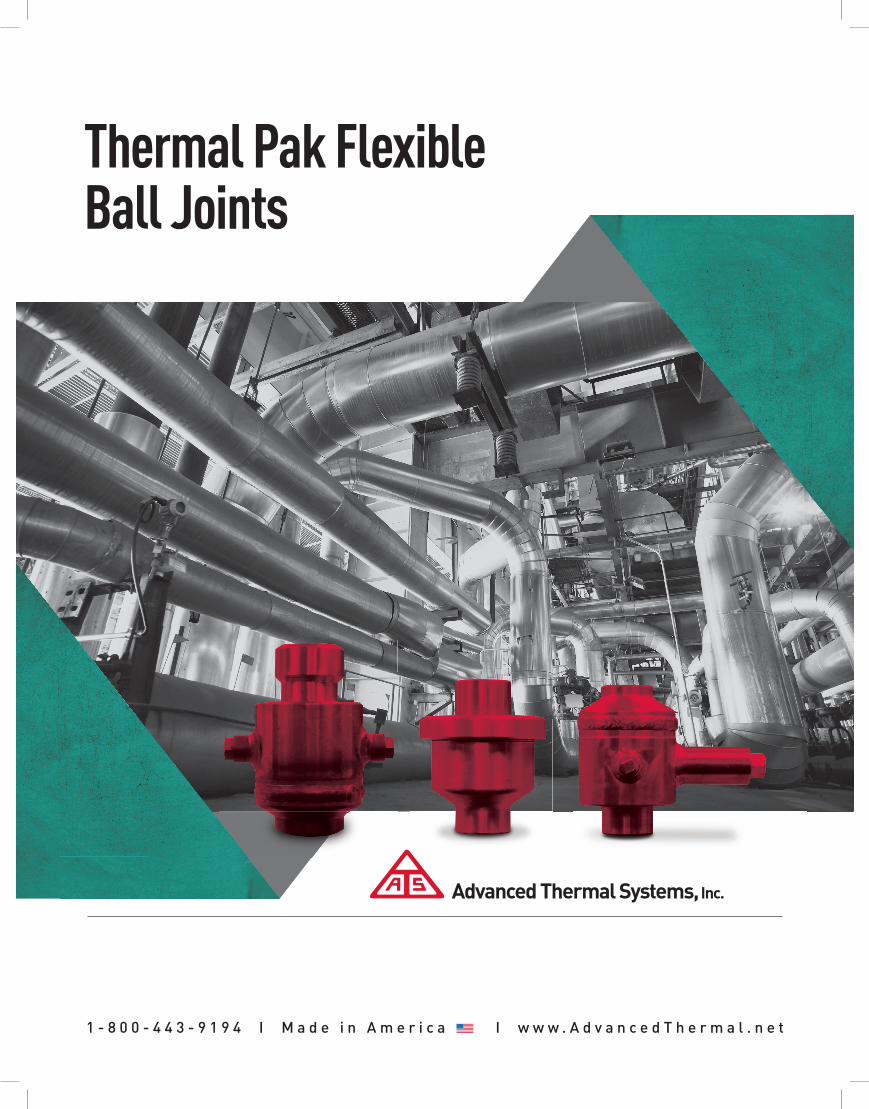
thermal pak flexible ball joints
TRANSCRIPT
1 - 8 0 0 - 4 4 3 - 9 1 9 4 I M a d e i n A m e r i c a 12 I w w w . A d v a n c e d T h e r m a l . n e t
Advanced Thermal Systems, Inc.
Thermal Pak Flexible Ball Joints
www.AdvancedThermal.netAdvanced Thermal Systems, Inc.
2 12 Proudly Manufactured in the U.S.A.
Advanced Thermal Systems Thermal Pak Flexible Ball Joints…
Benefits:
ATS ball joints provide benefits for many industrial, commercial and institutional users, such as petroleum refineries, oil production, chemical process plants, public utilities, schools, hospitals, industrial power plants, transportation terminals, manufacturing plants and basic metals industries.
ATS Ball Joints Provide Flexibility for Compensation of Expansion, Movement and Stress in:
STORAGE TANK PIPING• Thermal Expansion• Earth Movement• Settling or Tilting of Tanks
SOLAR ARRAY SYSTEMS
FIRE PROTECTION SYSTEMS
EQUIPMENT PIPING CONNECTIONS• Movement of Equipment• Movement of Piping• Exhaust Lines
UNDERGROUND PIPING SYSTEMS
SEISMIC SYSTEMS
HEATING AND COOLING SYSTEMS• Heating Lines• Cooling Lines• Boiler Connections
OIL RECOVERY SYSTEMS
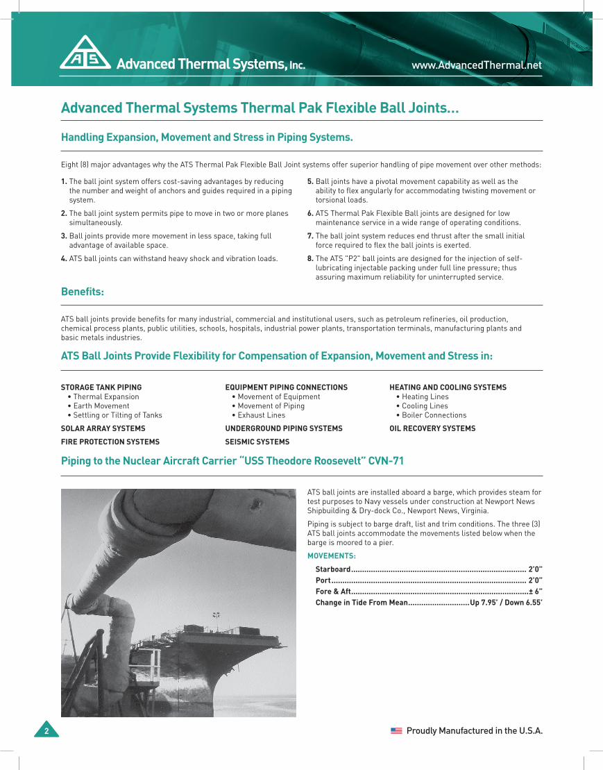
ATS ball joints are installed aboard a barge, which provides steam for test purposes to Navy vessels under construction at Newport News Shipbuilding & Dry-dock Co., Newport News, Virginia.
Piping is subject to barge draft, list and trim conditions. The three (3) ATS ball joints accommodate the movements listed below when the barge is moored to a pier.
MOVEMENTS:
Starboard ................................................................................ 2’0”Port ......................................................................................... 2’0”Fore & Aft .................................................................................± 6”Change in Tide From Mean ............................Up 7.95’ / Down 6.55’
Handling Expansion, Movement and Stress in Piping Systems.
1. The ball joint system offers cost-saving advantages by reducing the number and weight of anchors and guides required in a piping system.
2. The ball joint system permits pipe to move in two or more planes simultaneously.
3. Ball joints provide more movement in less space, taking full advantage of available space.
4. ATS ball joints can withstand heavy shock and vibration loads.
5. Ball joints have a pivotal movement capability as well as the ability to flex angularly for accommodating twisting movement or torsional loads.
6. ATS Thermal Pak Flexible Ball joints are designed for low maintenance service in a wide range of operating conditions.
7. The ball joint system reduces end thrust after the small initial force required to flex the ball joints is exerted.
8. The ATS "P2" ball joints are designed for the injection of self-lubricating injectable packing under full line pressure; thus assuring maximum reliability for uninterrupted service.
Eight (8) major advantages why the ATS Thermal Pak Flexible Ball Joint systems offer superior handling of pipe movement over other methods:
Piping to the Nuclear Aircraft Carrier “USS Theodore Roosevelt” CVN-71

1-800-443-9194 Advanced Thermal Systems, Inc.
Thermal Pak Flexible Ball Joints 12 3
TWO BALL JOINT LINKAGE
Applications
Linear Thermal Expansion / Contraction
The most common application for ATS ball joints is in long runs of piping which carry steam, hot water or other fluids at high temperatures and include offsets. Long lengths of pipe can expand considerably, flexing the joints as shown in the diagrams above. Any twisting of the pipe is handled easily by the ball joints. All major reactive forces of other systems are eliminated with ball joints. This installation requires less space than a pipe loop and provides a cost saving by the elimination of heavy anchors and guides.
Storage Tank Connections
ATS ball joints handle many types of pipe movement on storage tank connections. Two ATS ball joints can be used on a pipeline connected to a tank. The joints accommodate tank settling and tilting and protect the manifold from damage whenever movement occurs. ATS ball joints can handle seismic forces, pipe stresses and other reactive forces sometimes encountered in this type of application.
Stationary Piping to Moving Equipment
ATS ball joints can accommodate the movement of equipment in stationary piping systems. The multi-plane movement of the joints handles compound twisting motions eliminating damaging reactive forces in the system.
Moving Piping to Stationary Equipment
ATS ball joints are used when piping alignment is critical. Such alignment may occur with turbines, pumps, valves and other machinery. Misalignment coupled with expansion or other movement of the piping can seriously overstress equipment, which may result in costly damage. However, the combined angular flex and swivel movement in ATS ball joints compensates for misalignment and other piping movement without developing major reactive forces.
THREE BALL JOINT "KNUCKLE" ARRANGEMENT MAXIMUM DEFLECTION
THREE BALL JOINT LINKAGE
Piping Movement with ATS Ball Joints
THREE BALL JOINT "KNUCKLE" ARRANGEMENT MAXIMUM DEFLECTION
PIPING ALIGNMENT
Steam Injection (Oil Industry)
Ball joint linkages assist in oil recovery within the oil industry. Steam Flooding and Cyclic Steam Stimulation are methods used to loosen up heavy oil so that it can be recovered.

www.AdvancedThermal.netAdvanced Thermal Systems, Inc.
4 12 Proudly Manufactured in the U.S.A.
THREADED / SOCKET WELD
Thermal Pak Series “S” Flexible Ball Joints
The ATS Series "S" Ball Joint does not contain injectable packing and is only available with glass-filled Teflon® compression seals. Pressures are limited and maximum temperature is 400°F. Leakage is contained by adjustment of the retainer flange bolting or retainer cap. Available styles are the same as shown for all other series.
NOTES:1. Flanges for 30” Ball Joints are CL
125 and AWWA C 207 CL.E.2. Larger Flex Angle on application
for sizes 2-1/2” and larger.3. Stainless Steel for all or wetted
pressure containing components only are also available. Contact an ATS Representative for further information.
Series “S” Dimensions
STYLE 20 SOCKET WELD & THREAD-FEMALE (in.) WELDING ENDS (in.)
NOM. SIZE (NPS) ANG. FLEX A B C A B C
1 1⁄4 - 1 1⁄2 30° 6 1⁄16 3 3⁄8 5 1⁄8 5 3⁄8 2 11⁄16 5 1⁄82 33° 7 3⁄16 4 5 3⁄4 6 3⁄8 3 3⁄16 5 3⁄4
2 1⁄2 15° Not Available 6 3⁄8 3 3⁄16 5 3⁄4
Style 20
NOM. SIZE
(NPS)
ANG. FLEX
WELD ENDS (in.) 150 LB. FLANGED (in.) 300 LB. FLANGED (in.)
A B C A B C A B C
3 15° 7 3⁄4 4 1⁄8 7 1⁄2 13 1⁄4 6 7⁄8 7 1⁄2 14 7 1⁄4 8 1⁄44 15° 8 1⁄2 4 3⁄8 9 14 1⁄2 7 3⁄8 9 15 1⁄4 7 3⁄4 105 15° 10 7⁄16 5 1⁄4 11 1⁄8 17 7⁄16 8 3⁄4 11 1⁄8 18 3⁄16 9 1⁄8 116 15° 14 1⁄4 7 3⁄16 12 21 1⁄4 10 11⁄16 12 22 11 1⁄16 12 1⁄28 15° 16 8 14 3⁄4 24 12 14 3⁄4 24 3⁄4 12 3⁄8 15
10 15° 16 1⁄2 8 1⁄4 17 1⁄8 24 1⁄2 12 1⁄4 17 1⁄8 25 3⁄4 12 7⁄8 17 1⁄212 15° 16 8 11⁄16 19 1⁄4 25 13 3⁄16 19 1⁄4 26 1⁄4 13 13⁄16 20 1⁄214 15° 19 1⁄2 10 1⁄16 22 1⁄8 29 1⁄2 15 1⁄16 22 1⁄8 30 3⁄4 15 11⁄16 2316 15° 21 3⁄8 11 1⁄2 24 7⁄8 31 3⁄8 16 1⁄2 24 7⁄8 32 1⁄4 17 1⁄4 25 1⁄218 15° 23 1⁄4 12 1⁄2 28 34 1⁄4 18 28 35 3⁄4 18 3⁄4 2820 15° 24 11 1⁄2 30 15⁄16 35 3⁄8 17 3⁄16 30 15⁄16 36 3⁄4 17 7⁄8 30 15⁄1624 15° 25 13 36 1⁄4 37 19 36 1⁄4 38 1⁄4 19 5⁄8 36 1⁄430 15° 31 1⁄2 16 3⁄4 44 3⁄8 41 3⁄4 21 7⁄8 44 3⁄8 CONTACT FACTORY
WELD END
A
C
B
±1/8
ANGU
LAR
FLEX
FLANGED END
A
B
CMAXDIA
±1/4
ANGU
LAR
FLEX
S-SERIES
5
1
2
4
3
1. RETAINER FLANGE2. SOCKET3. BALL4. GLASS-FILLED TEFLON®
COMPRESSION SEAL5. FLANGE BOLTING
STYLE 20
ANGU
LAR
FLEX
A
B
±1/8
C
1-800-443-9194 Advanced Thermal Systems, Inc.
Thermal Pak Flexible Ball Joints 12 5
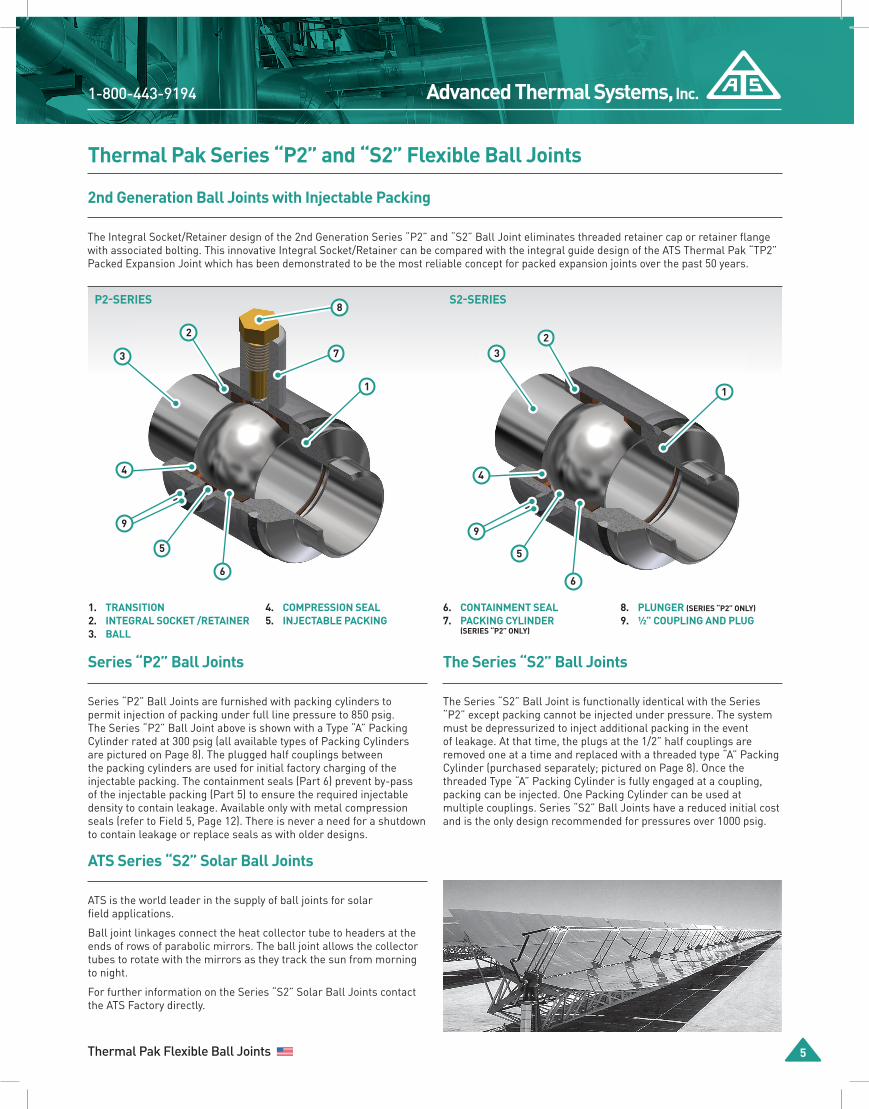
P2-SERIES
Thermal Pak Series “P2” and “S2” Flexible Ball JointsThermal Pak Series “S” Flexible Ball Joints
2nd Generation Ball Joints with Injectable Packing
The Integral Socket/Retainer design of the 2nd Generation Series “P2” and “S2” Ball Joint eliminates threaded retainer cap or retainer flange with associated bolting. This innovative Integral Socket/Retainer can be compared with the integral guide design of the ATS Thermal Pak “TP2” Packed Expansion Joint which has been demonstrated to be the most reliable concept for packed expansion joints over the past 50 years.
Series “P2” Ball Joints
Series “P2” Ball Joints are furnished with packing cylinders to permit injection of packing under full line pressure to 850 psig. The Series “P2” Ball Joint above is shown with a Type “A” Packing Cylinder rated at 300 psig (all available types of Packing Cylinders are pictured on Page 8). The plugged half couplings between the packing cylinders are used for initial factory charging of the injectable packing. The containment seals (Part 6) prevent by-pass of the injectable packing (Part 5) to ensure the required injectable density to contain leakage. Available only with metal compression seals (refer to Field 5, Page 12). There is never a need for a shutdown to contain leakage or replace seals as with older designs.
ATS Series “S2” Solar Ball Joints
ATS is the world leader in the supply of ball joints for solar field applications.
Ball joint linkages connect the heat collector tube to headers at the ends of rows of parabolic mirrors. The ball joint allows the collector tubes to rotate with the mirrors as they track the sun from morning to night.
For further information on the Series “S2” Solar Ball Joints contact the ATS Factory directly.
The Series “S2” Ball Joints
The Series “S2” Ball Joint is functionally identical with the Series “P2” except packing cannot be injected under pressure. The system must be depressurized to inject additional packing in the event of leakage. At that time, the plugs at the 1/2” half couplings are removed one at a time and replaced with a threaded type “A” Packing Cylinder (purchased separately; pictured on Page 8). Once the threaded Type “A” Packing Cylinder is fully engaged at a coupling, packing can be injected. One Packing Cylinder can be used at multiple couplings. Series “S2” Ball Joints have a reduced initial cost and is the only design recommended for pressures over 1000 psig.
1. TRANSITION2. INTEGRAL SOCKET /RETAINER3. BALL
3 3
4 4
1 1
7
8
2 2
5 5
66
9
S2-SERIES
4. COMPRESSION SEAL5. INJECTABLE PACKING
6. CONTAINMENT SEAL7. PACKING CYLINDER
(SERIES “P2” ONLY)
8. PLUNGER (SERIES “P2” ONLY)
9. 1⁄2” COUPLING AND PLUG
9
www.AdvancedThermal.netAdvanced Thermal Systems, Inc.
6 12 Proudly Manufactured in the U.S.A.
1. a. Eliminates the in-service field error of over-tightening the retainer flange bolting or retainer cap which will greatly increase flex torque values and may result in freezing the ball in its socket.
b. To contain leakage. It is best to inject additional packing vs tightening of the retainer flange bolting or threaded cap since packing injection can be controlled to minimize the flex torque value and produces a more positive leak containment method.
The use of "metal only” seals in the Thermal Pak “P2” and “S2” Ball Joints produces more constant flex torque values for the life of the piping system vs. ball joints with pressure-molded compression seals (gaskets). In addition, the breakaway force is considerably less with the metal seals than with the molded seals. This is especially true in hot service where the ball has not moved for long periods.
The “Injection of Packing under full line pressure” concept was first introduced to ball joints by ATS in 1979. This concept has been proven in thousands of installations world-wide. Where leakage is apparent, it has been field proven that injectable packing will contain the leakage even when the compression seals are worn or wire-drawn. The injectable packing adjusts for wear and fills the void created by wire-drawing, thus the need to replace seals has been eliminated. As it is no longer necessary to replace seals to contain leakage, the integral design of the Thermal Pak Series “P2” and “S2” Ball Joints is the logical design extension to increase reliability and decrease initial and operating costs.
NOTES:1. Larger sizes on application2. Threaded retainer cap furnished
for 1-1/4” to 2-1/2” Series "S".
NOTES:1. Series “S2” Ball Joints are available on application to 3000 psig/800° F.2. Series “P2” Ball Joints are limited to 850 psig.3. Refer to Page 12, field 7 for Packing Cylinder Pressure Ratings.4. Series “P2” and “S2” ¾” to 2” sizes are available with threaded, weld,
flanged, or socket weld ends.5. Series “P2” and “S2” sizes 2-1/2’’ and larger series are available with
weld, grooved ends or flanged ends.6. When ends are beveled for welding, specify pipe schedule or preferably
the “wall thickness.” Bear in mind that “Standard Wall” is the same as “Sch. 40” to 10” size only and that “EH”is the same as “Sch.80” only to “8” size.” The wall thickness of “EH” pipe 8” and larger is ½”.
7. Refer to Page 12 for “HOW TO ORDER “
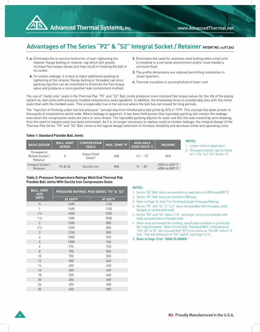
Advantages of The Series “P2” & “S2” Integral Socket / Retainer PATENT NO.: 4,671,543
2. Eliminates the need for stainless steel bolting when a ball joint is installed in a corrosive environment and/or must handle a corrosive fluid.
3. The profile dimensions are reduced permitting installation in closer quarters.
4. Thermal insulation is accomplished at lower cost.
Table 1: Standard Flexible Ball Joints
BASIC DESIGN BALL JOINT SERIES
COMPRESSION SEALS MAX. TEMP. °F AVAILABLE
SIZES (NOTE 1) PACKING
Threaded or Bolted Socket /
RetainerS Glass Filled
Teflon® 400 1 1⁄4” - 12” N/A
Integral Socket /Retainer P2 & S2 Ductile Iron 800 3⁄4” - 30” 350H to 600º F
400H to 800º F
Table 2: Pressure-Temperature Ratings Weld End Thermal Pak Flexible Ball Joints With Ductile Iron Compression Seals
BALL JOINT SIZE
(NPS)
PRESSURE RATINGS, PSIG SERIES “P2” & “S2”
AT 650°F AT 800°F3⁄4 1600 11501 1600 1150
1 1⁄4 1500 10501 1⁄2 1500 10502 1200 850
2 1⁄2 1200 8503 1200 8504 1000 7405 1000 7406 975 7208 750 550
10 750 55012 600 44014 600 44016 600 44018 500 44020 450 40024 450 40030 450 350

1-800-443-9194 Advanced Thermal Systems, Inc.
Thermal Pak Flexible Ball Joints 12 7
SERIES "P2" 3/4" TO 30" LARGER SIZES ON APPLICATION
Series “P2” & ”S2” Dimensions
ALL PRESSURE CONTAINING COMPONENTS ARE CARBON STEEL. ALSO AVAILABLE IN STAINLESS STEEL.
NOTES:1. Add 1-1/8” to “R” when Type “B” Packing Cylinders are used.2. Stainless, Aluminum Bronze, or Monel Plungers can be furnished for
humid and corrosive applications.
Series “P2” and “S2” Style 20 Dimensions
STYLE 20 SOCKET WELD & THREAD-FEMALE (in.) WELDING ENDS (in.)
NOM. SIZE (NPS) ANG. FLEX A B C A B C3⁄4 - 1 33° 6 1⁄2 3 7⁄16 3 7⁄16 O/A O/A O/A
1 1⁄4 - 1 1⁄2 30° 6 11⁄16 3 3⁄8 3 7⁄8 6 2 11⁄16 3 7⁄82 33° 7 7⁄16 4 4 7⁄16 6 5⁄8 3 3⁄16 4 7⁄16
Style 20
NOM. SIZE
(NPS)
ANG. FLEX
WELD ENDS (in.) 150 LB. FLANGED (in.) 300 LB. FLANGED (in.)
A B C A B C A B C
2 1⁄2 15° 6 5⁄8 3 3⁄16 4 7⁄16 12 1⁄8 5 15⁄16 7 12 5⁄8 6 3⁄16 7 1⁄23 15° 8 3⁄8 4 1⁄8 5 13⁄16 13 7⁄8 6 7⁄8 7 1⁄2 14 5⁄8 7 1⁄4 8 1⁄44 15° 9 4 3⁄8 6 11⁄16 15 7 3⁄8 9 15 3⁄4 7 3⁄4 105 15° 11 1⁄8 5 1⁄4 8 5⁄8 18 1⁄8 8 3⁄4 10 18 7⁄8 9 1⁄8 116 15° 13 1⁄8 7 3⁄16 9 7⁄8 20 1⁄8 10 11⁄16 11 20 7⁄8 11 1⁄16 12 1⁄28 15° 14 1⁄2 8 12 22 1⁄2 12 13 1⁄2 23 1⁄4 12 3⁄8 15
10 15° 15 3⁄8 8 1⁄4 14 23 3⁄8 12 1⁄4 16 24 5⁄8 12 7⁄8 17 1⁄212 15° 16 1⁄4 8 11⁄16 16 25 1⁄4 13 3⁄16 19 26 1⁄2 13 13⁄16 20 1⁄214 15° 18 13⁄16 10 1⁄16 18 7⁄8 28 13⁄16 15 1⁄16 21 30 1⁄16 15 11⁄16 2316 15° 21 3⁄8 11 1⁄2 21 7⁄8 31 3⁄8 16 1⁄2 23 1⁄2 32 7⁄8 17 1⁄4 25 1⁄218 15° 23 3⁄4 12 1⁄2 24 1⁄8 34 3⁄4 18 25 36 1⁄4 18 3⁄4 2820 15° 23 3⁄4 11 1⁄2 26 7⁄8 35 1⁄8 17 3⁄16 27 1⁄2 36 1⁄2 17 7⁄8 30 1⁄224 15° 26 1⁄2 13 32 1⁄8 38 1⁄2 19 32 39 3⁄4 19 5⁄8 3630 15° 32 5⁄8 16 3⁄4 39 3⁄4 42 7⁄8 21 1⁄2 38 3⁄4 CONTACT FACTORY
3. Other Configuration styles are available; please consult your nearest ATS Representative or Factory Direct for more information.
4. Stainless Steel for all or wetted pressure containing components only are also available. Contact an ATS Representative for further information.
NOMINAL SIZE (NPS) DIM. R (in.)
3⁄4 and 1 5 5⁄81 1⁄4 and 1 1⁄2 5 13⁄162 and 2 1⁄2 6 1⁄8
3 6 11⁄164 7 1⁄85 8 1⁄166 8 11⁄168 9 3⁄4
10 10 3⁄412 11 3⁄414 13 3⁄1616 14 11⁄1618 15 7⁄820 17 1⁄424 19 7⁄830 23 5⁄8
Series “P2” Packing Cylinder / Plunger Assembly - Clearance
RPlungerEngaged
Plunger(see Note 2)
Type A Packing Cylinder
(see Note 1)
Plunger RemovalClearance
2 3"4
WELD END
THREADED END
A ±1/8
B
C
ANGU
LAR
FLEX
A ±1/8
B
C
ANGU
LAR
FLEX
FLANGED END
B
A ±1/4
CANGULAR FLEX
www.AdvancedThermal.netAdvanced Thermal Systems, Inc.
8 12 Proudly Manufactured in the U.S.A.
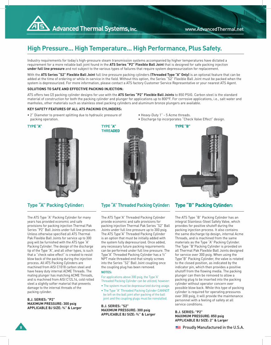
TYPE “A”
Type “A” Packing Cylinder:
The ATS Type “A” Packing Cylinder for many years has provided economic and safe provisions for packing injection Thermal Pak Series “P2” Ball Joints under full line pressure. Unless otherwise specified all ATS Thermal Pak Flexible Ball Joints for service up to 300 psig will be furnished with the ATS type “A” Packing Cylinder. The design of the discharge tip of the Type “A”, and all other types, is such that a “check valve effect” is created to resist blow back of the packing during the injection process. All ATS Packing Cylinders are machined from AISI C1018 carbon steel and have heavy duty internal ACME Threads. The mating plunger has matching ACME Threads, and is machined from AISI C12L14, cold rolled steel a slightly softer material that prevents damage to the internal threads of the packing cylinder.
B.J. SERIES: "P2"MAXIMUM PRESSURE: 300 psigAPPLICABLE BJ SIZE: 3⁄4” & Larger
Type “A” Threaded Packing Cylinder:
The ATS Type”A” Threaded Packing Cylinder provide economic and safe provisions for packing injection Thermal Pak Series “S2” Ball Joints under full line pressure up to 300 psig. The ATS Type”A” Threaded Packing Cylinder is an option that must be initially added with the system fully depressurized. Once added, any necessary future packing requirements can be performed under full line pressure. The Type”A” Threaded Packing Cylinder has a ½” NPT male threaded end that simply screws into the Series “S2” Ball Joint coupling once the coupling plug has been removed.NOTES:For applications above 300 psig, the Type”A” Threaded Packing Cylinder can be utilized, however:• The system must be depressurized during usage.• The Type “A” Threaded Packing Cylinder CANNOT
be left on the ball joint after packing of the ball joint and the coupling plugs must be reinstalled.
B.J. SERIES: "S2"MAXIMUM PRESSURE: 300 psigAPPLICABLE BJ SIZE: 3⁄4” & Larger
Type “B” Packing Cylinder:
The ATS Type “B” Packing Cylinder has an integral Stainless-Steel Safety Valve, which provides for positive shutoff during the packing injection process. It also contains the same discharge tip design, internal Acme Threads, and is machined from the same materials as the Type “A” Packing Cylinder. The Type “B”Packing Cylinder is provided on all Thermal Pak Flexible Ball Joints designed for service over 300 psig. When using the Type”B” Packing Cylinder, the valve is rotated to the closed position, as indicated by the indicator pin, which then provides a positive shutoff from the flowing media. The packing plunger can then be removed to allow a packing plug to be inserted into the packing cylinder without operator concern over possible blow back. While this type of packing cylinder is required for operating pressures over 300 psig, it will provide the maintenance personnel with a feeling of safety at all service conditions.
B.J. SERIES: "P2"MAXIMUM PRESSURE: 850 psigAPPLICABLE BJ SIZE: 2” & Larger
TYPE “A”THREADED
TYPE “B”TYPE “A”TYPE “A”
Type “A” Packing Cylinder: Type “B” Packing Cylinder:
TYPE “B”TYPE “B”TYPE “A”THREADED
High Pressure... High Temperature... High Performance, Plus Safety.
Industry requirements for today’s high-pressure steam transmission systems accompanied by higher temperatures have dictated a requirement for a more reliable ball joint found in the ATS Series “P2” Flexible Ball Joint that is designed for safe packing injection under full line pressure and not subject to the various types of failures that require system depressurization for replacement.
With the ATS Series “S2” Flexible Ball Joint full line pressure packing cylinders (Threaded Type ”A” Only) is an optional feature that can be added at the time of ordering or while in-service in the field. Without this option, the Series “S2” Flexible Ball Joint must be packed when the system is depressurized. For more information, please contact a ATS factory Customer Service Representative or your nearest ATS Agent.
SOLUTIONS TO SAFE AND EFFECTIVE PACKING INJECTION:
ATS offers two (2) packing cylinder designs for use with the ATS Series “P2” Flexible Ball Joints to 850 PSIG. Carbon steel is the standard material of construction for both the packing cylinder and plunger for applications up to 800°F. For corrosive applications, i.e., salt water and manholes, other materials such as stainless steel packing cylinders and aluminum bronze plungers are available.
KEY SAFETY FEATURES OF ALL ATS PACKING CYLINDERS:
• 2” Diameter to prevent splitting due to hydraulic pressure ofpacking operation.
• Heavy-Duty 1” - 5 Acme threads.• Discharge tip incorporates “Check Valve Effect” design.
1-800-443-9194 Advanced Thermal Systems, Inc.
Thermal Pak Flexible Ball Joints 12 9
High Pressure... High Temperature... High Performance, Plus Safety.
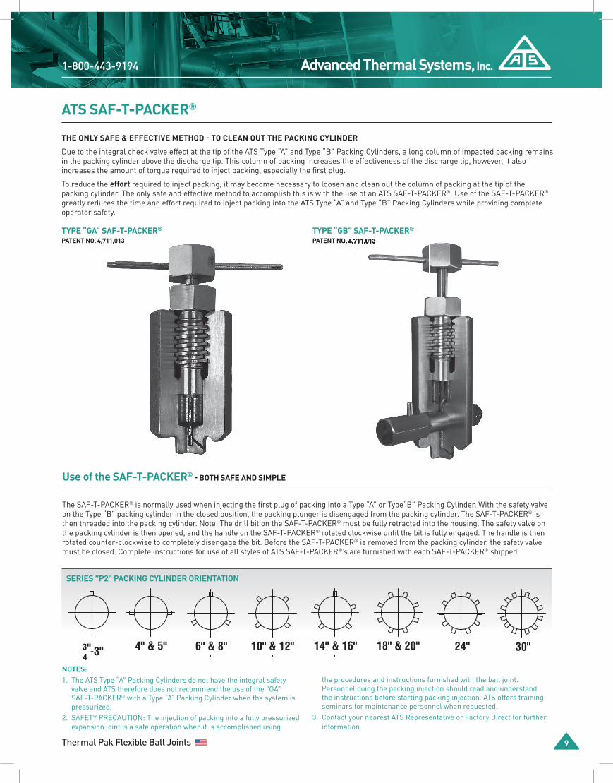
THE ONLY SAFE & EFFECTIVE METHOD - TO CLEAN OUT THE PACKING CYLINDER
Due to the integral check valve effect at the tip of the ATS Type “A” and Type “B” Packing Cylinders, a long column of impacted packing remains in the packing cylinder above the discharge tip. This column of packing increases the effectiveness of the discharge tip, however, it also increases the amount of torque required to inject packing, especially the first plug.
To reduce the effort required to inject packing, it may become necessary to loosen and clean out the column of packing at the tip of the packing cylinder. The only safe and effective method to accomplish this is with the use of an ATS SAF-T-PACKER®. Use of the SAF-T-PACKER® greatly reduces the time and effort required to inject packing into the ATS Type “A” and Type “B” Packing Cylinders while providing complete operator safety.
ATS SAF-T-PACKER®
4" & 5"
-3"34
6" & 8"
14" & 16"10" & 12"
24"18" & 20"
"
30"
4" & 5"
-3"34
6" & 8"
14" & 16"10" & 12"
24"18" & 20"
"
30"
4" & 5"
-3"34
6" & 8"
14" & 16"10" & 12"
24"18" & 20"
"
30"
4" & 5"
-3"34
6" & 8"
14" & 16"10" & 12"
24"18" & 20"
"
30"
4" & 5"
-3"34
6" & 8"
14" & 16"10" & 12"
24"18" & 20"
"
30"
4" & 5"
-3"34
6" & 8"
14" & 16"10" & 12"
24"18" & 20"
"
30"
4" & 5"
-3"34
6" & 8"
14" & 16"10" & 12"
24"18" & 20"
"
30"
SERIES "P2" PACKING CYLINDER ORIENTATION
NOTES: 1. The ATS Type “A” Packing Cylinders do not have the integral safety
valve and ATS therefore does not recommend the use of the "GA" SAF-T-PACKER® with a Type “A” Packing Cylinder when the system is pressurized.
2. SAFETY PRECAUTION: The injection of packing into a fully pressurized expansion joint is a safe operation when it is accomplished using
the procedures and instructions furnished with the ball joint. Personnel doing the packing injection should read and understand the instructions before starting packing injection. ATS offers training seminars for maintenance personnel when requested.
3. Contact your nearest ATS Representative or Factory Direct for further information.
Use of the SAF-T-PACKER® - BOTH SAFE AND SIMPLE
The SAF-T-PACKER® is normally used when injecting the first plug of packing into a Type “A” or Type“B” Packing Cylinder. With the safety valve on the Type “B” packing cylinder in the closed position, the packing plunger is disengaged from the packing cylinder. The SAF-T-PACKER® is then threaded into the packing cylinder. Note: The drill bit on the SAF-T-PACKER® must be fully retracted into the housing. The safety valve on the packing cylinder is then opened, and the handle on the SAF-T-PACKER® rotated clockwise until the bit is fully engaged. The handle is then rotated counter-clockwise to completely disengage the bit. Before the SAF-T-PACKER® is removed from the packing cylinder, the safety valve must be closed. Complete instructions for use of all styles of ATS SAF-T-PACKER®’s are furnished with each SAF-T-PACKER® shipped.
TYPE “GA” SAF-T-PACKER®
PATENT NO. 4,711,013TYPE “GB” SAF-T-PACKER®
PATENT NO. 4,711,013
4" & 5"
-3"34
6" & 8"
14" & 16"10" & 12"
24"18" & 20"
"
30"
PATENT NO. 4,711,013
www.AdvancedThermal.netAdvanced Thermal Systems, Inc.
10 12 Proudly Manufactured in the U.S.A.
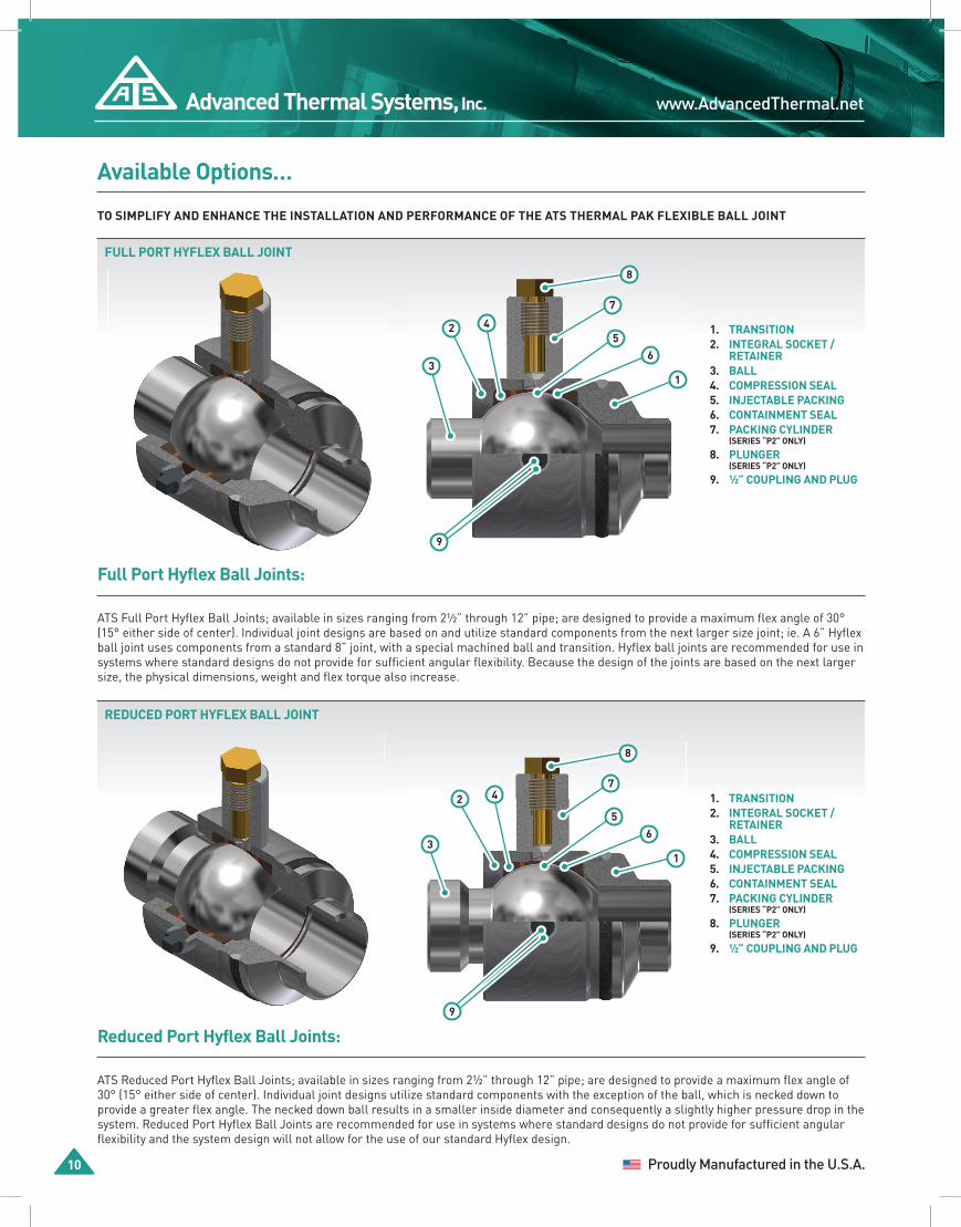
Full Port Hyflex Ball Joints:
ATS Full Port Hyflex Ball Joints; available in sizes ranging from 2½” through 12” pipe; are designed to provide a maximum flex angle of 30° (15° either side of center). Individual joint designs are based on and utilize standard components from the next larger size joint; ie. A 6” Hyflex ball joint uses components from a standard 8” joint, with a special machined ball and transition. Hyflex ball joints are recommended for use in systems where standard designs do not provide for sufficient angular flexibility. Because the design of the joints are based on the next larger size, the physical dimensions, weight and flex torque also increase.
Reduced Port Hyflex Ball Joints:
ATS Reduced Port Hyflex Ball Joints; available in sizes ranging from 2½” through 12” pipe; are designed to provide a maximum flex angle of 30° (15° either side of center). Individual joint designs utilize standard components with the exception of the ball, which is necked down to provide a greater flex angle. The necked down ball results in a smaller inside diameter and consequently a slightly higher pressure drop in the system. Reduced Port Hyflex Ball Joints are recommended for use in systems where standard designs do not provide for sufficient angular flexibility and the system design will not allow for the use of our standard Hyflex design.
Available Options…
TO SIMPLIFY AND ENHANCE THE INSTALLATION AND PERFORMANCE OF THE ATS THERMAL PAK FLEXIBLE BALL JOINT
FULL PORT HYFLEX BALL JOINT
REDUCED PORT HYFLEX BALL JOINT
1. TRANSITION2. INTEGRAL SOCKET / RETAINER3. BALL4. COMPRESSION SEAL5. INJECTABLE PACKING6. CONTAINMENT SEAL7. PACKING CYLINDER (SERIES “P2” ONLY)
8. PLUNGER (SERIES “P2” ONLY)
9. 1⁄2” COUPLING AND PLUG
7
56
8
9
13
2 4
1. TRANSITION2. INTEGRAL SOCKET / RETAINER3. BALL4. COMPRESSION SEAL5. INJECTABLE PACKING6. CONTAINMENT SEAL7. PACKING CYLINDER (SERIES “P2” ONLY)
8. PLUNGER (SERIES “P2” ONLY)
9. 1⁄2” COUPLING AND PLUG
7
56
8
9
13
2 4
1-800-443-9194 Advanced Thermal Systems, Inc.
Thermal Pak Flexible Ball Joints 12 11
Available Options…
TO SIMPLIFY AND ENHANCE THE INSTALLATION AND PERFORMANCE OF THE ATS THERMAL PAK FLEXIBLE BALL JOINT
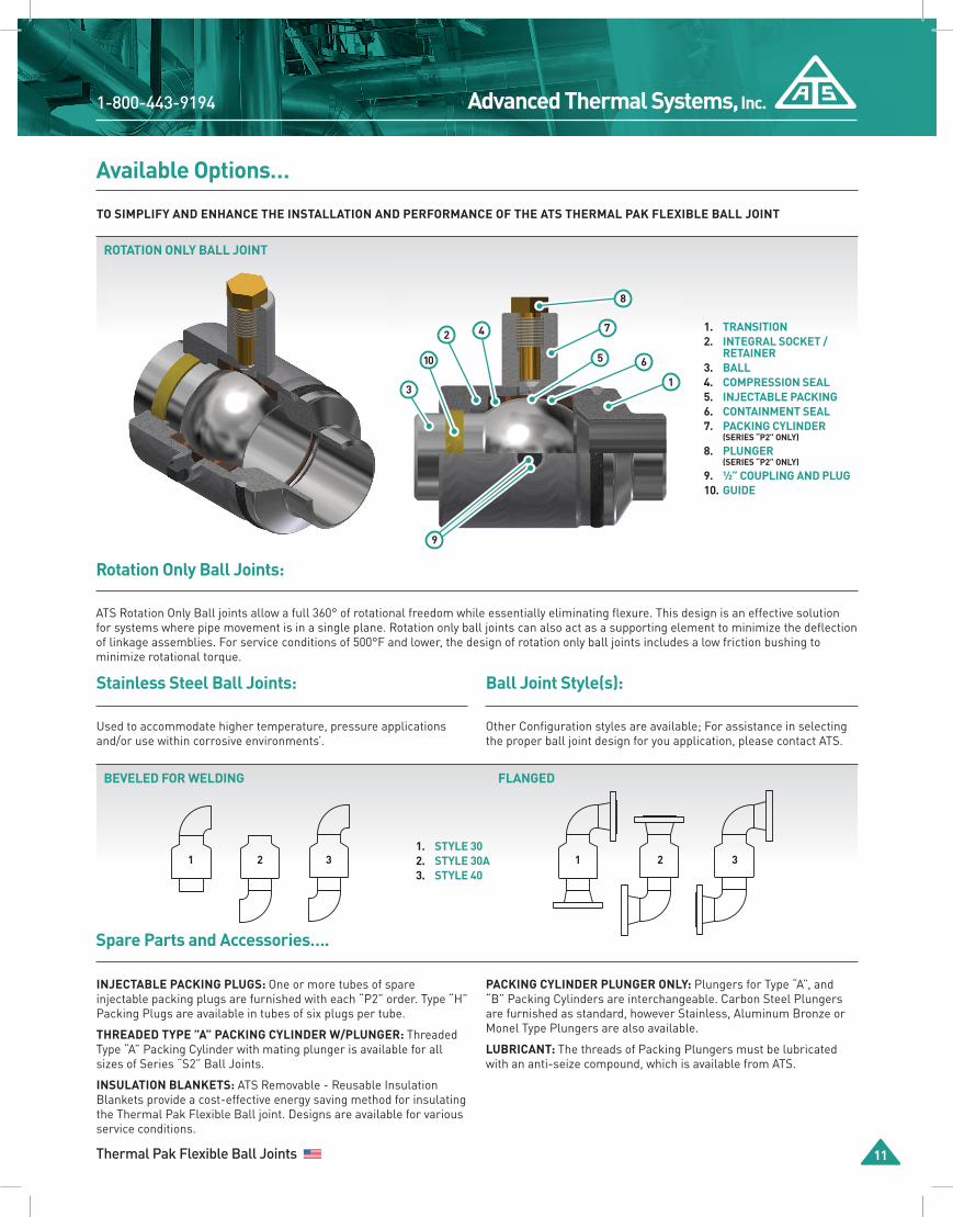
ROTATION ONLY BALL JOINT
Rotation Only Ball Joints:
ATS Rotation Only Ball joints allow a full 360° of rotational freedom while essentially eliminating flexure. This design is an effective solution for systems where pipe movement is in a single plane. Rotation only ball joints can also act as a supporting element to minimize the deflection of linkage assemblies. For service conditions of 500°F and lower, the design of rotation only ball joints includes a low friction bushing to minimize rotational torque.
Stainless Steel Ball Joints:
Used to accommodate higher temperature, pressure applications and/or use within corrosive environments’.
Ball Joint Style(s):
Other Configuration styles are available; For assistance in selecting the proper ball joint design for you application, please contact ATS.
1. TRANSITION2. INTEGRAL SOCKET / RETAINER3. BALL4. COMPRESSION SEAL5. INJECTABLE PACKING6. CONTAINMENT SEAL7. PACKING CYLINDER (SERIES “P2” ONLY)
8. PLUNGER (SERIES “P2” ONLY)
9. 1⁄2” COUPLING AND PLUG10. GUIDE
7
5 6
8
9
1
10
3
2 4
Spare Parts and Accessories….
INJECTABLE PACKING PLUGS: One or more tubes of spare injectable packing plugs are furnished with each “P2” order. Type “H” Packing Plugs are available in tubes of six plugs per tube.
THREADED TYPE ”A” PACKING CYLINDER W/PLUNGER: Threaded Type “A” Packing Cylinder with mating plunger is available for all sizes of Series “S2” Ball Joints.
INSULATION BLANKETS: ATS Removable - Reusable Insulation Blankets provide a cost-effective energy saving method for insulating the Thermal Pak Flexible Ball joint. Designs are available for various service conditions.
PACKING CYLINDER PLUNGER ONLY: Plungers for Type “A”, and “B” Packing Cylinders are interchangeable. Carbon Steel Plungers are furnished as standard, however Stainless, Aluminum Bronze or Monel Type Plungers are also available.
LUBRICANT: The threads of Packing Plungers must be lubricated with an anti-seize compound, which is available from ATS.
BEVELED FOR WELDING FLANGED
1 2 3 1 2 31. STYLE 302. STYLE 30A3. STYLE 40

www.AdvancedThermal.netAdvanced Thermal Systems, Inc.
12 12 Proudly Manufactured in the U.S.A.
How To Order….
To insure correct and efficient production of Thermal Pak Flexible Ball Joint Order, use full catalog number designation as described in example below
1O” P2-SWW-350H-70-20-A-X1. 2. 3. 4. 5. 6. 7. 8.
Field Number: CATALOG NUMBER
1. PIPE SIZE
2. BALL JOINT SERIES: S, P2, S2
3. END PREPARATION:
SWW = Standard Wall, Weld Ends EHW = Extra Heavy Wall, Weld Ends 15F = 150 lb. Flanged 30F = 300 lb. Flanged XXX = Other or Combination
(Connections: Specify Ball End first then the Transition End)
4. PACKING DESIGNATION:
Omit for "S" Series
Field 7: Packing Cylinders
TYPE MAXIMUM PRESSURE APPLICABLE BJ SIZE
“A” 300 psig 1 1⁄2” & larger
“B” 850 psig 1 1⁄2” & largerField 4: Packing Code
PACKING CODE (Field 8)
BRAIDED RING
PACKING
INJECTABLE PACKING SERVICE MAX. TEMP.
(°F)
350H Reinforced Graphite “HPI®” FLAKE
GRAPHITE
Steam 600
400H Reinforced Graphite Steam 800
5. INNER AND OUTER COMPRESSION SEAL:
20 - Glass Filled Teflon®, 400ºF Max. ("S" Series Only) 70 - Ductile Iron, 800ºF Max ("P2" & "S2" Series Only)
6. BALL JOINT STYLE:
20 - Standard Style (refer to Page 4 & 7)XX - Other (See Page 11 or Contact Factory Direct)
7. TYPE PACKING CYLINDERS ("P2" Series Only):
8. SPECIAL OPTION:
RP-HF = Reduced Port HyflexHF = Full Port HyflexRO = Rotation OnlyXXX = Other
Flexible Ball Joint Shipping Weight (lbs.) Thermal Pak “P2” and “S2”
BJ SIZE
(NPS)
SWW & EHW WELD END
150 lb. FLANGED END
300 lb. FLANGED END
SERIES “P2”
SERIES “S2”
SERIES “P2”
SERIES “S2”
SERIES “P2”
SERIES “S2”
3⁄4 12 10 16 14 20 181 12 10 16 14 22 20
1 1⁄4 14 12 22 20 26 241 1⁄2 14 12 24 22 32 302 18 16 31 29 35 33
2 1⁄2 18 16 38 36 39 373 34 31 59 56 56 534 45 40 77 72 87 825 75 70 117 112 137 132 6 126 119 176 169 208 201
BJ SIZE
(NPS)
SWW & EHW WELD END
150 lb. FLANGED END
300 lb. FLANGED END
SERIES “P2”
SERIES “S2”
SERIES “P2”
SERIES “S2”
SERIES “P2”
SERIES “S2”
8 180 173 260 253 320 313 10 220 210 332 322 408 398 12 280 270 452 442 560 55014 425 408 647 630 805 78816 640 624 922 906 1,140 1,12418 1,050 1,026 1,356 1,332 1,660 1,63620 1,500 1,476 1,876 1,852 2,260 2,23624 2,200 2,170 2,740 2,710 3,280 3,25030 3,800 3,764 4,600 4,564 4,900 4,864
1-800-443-9194 Advanced Thermal Systems, Inc.
Thermal Pak Flexible Ball Joints 12 13
Engineering Information…
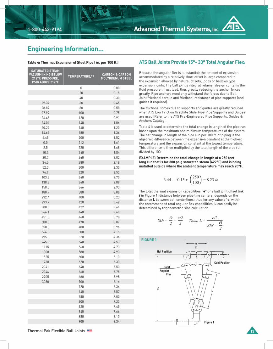
ATS Ball Joints Provide 15°- 33° Total Angular Flex:
Because the angular flex is substantial; the amount of expansion accommodated by a relatively short offset is large compared to the expansion allowed by natural offsets, loops or bellows type expansion joints. The ball joint’s integral retainer design contains the fluid pressure thrust load, thus greatly reducing the anchor forces greatly. Pipe anchors need only withstand the forces due to Ball Joint frictional torque and frictional resistance of pipe supports (and guides if required).
The frictional forces due to supports and guides are greatly reduced when ATS Low Friction Graphite Slide Type Pipe Supports and Guides are used (Refer to the ATS Pre-Engineered Pipe Supports, Guides & Anchors Catalog).
Table 4 is used to determine the total change in length of the pipe run based upon the maximum and minimum temperatures of the system. The net change in length of the pipe run per 100 ft. of piping is the algebraic difference between the expansion constant at the highest temperature and the expansion constant at the lowest temperature. This difference is then multiplied by the total length of the pipe run divided by 100.
EXAMPLE: Determine the total change in length of a 250 feet long run that is for 300 psig saturated steam (422°F) and is being installed outside where the ambient temperature may reach 20°F.
The total thermal expansion capabilities “e” of a ball joint offset link l in Figure 1 (distance between pipe line centers) depends on the distance L between ball centerlines; thus for any value of e, within the recommended total angular flex capabilities, L can easily be determined by trigonometric sine calculation:
SIN = ϴ2
= e/22
Thus: L =SIN = ϴ
2
e/2
Table 4: Thermal Expansion of Steel Pipe ( in. per 100 ft.)
SATURATED STEAM VACUUM IN HG BELOW
212°F, PRESSURE, PSIG ABOVE 212°F
TEMPERATURE,°F CARBON & CARBON MOLYBDENUM STEEL
0 0.0020 0.1540 0.30
29.39 60 0.4528.89 80 0.5827.99 100 0.7526.48 120 0.9124.04 140 1.0620.27 160 1.2014.63 180 1.366.45 200 1.520.0 212 1.612.5 220 1.68
10.3 240 1.8420.7 260 2.0234.5 280 2.1852.3 300 2.3574.9 320 2.53
103.3 340 2.70138.3 360 2.88150.0 366 2.93180.9 380 3.06232.4 400 3.23293.7 420 3.42300.0 422 3.44366.1 440 3.60451.3 460 3.78500.0 470 3.87550.3 480 3.96664.3 500 4.15795.3 520 4.34945.3 540 4.531115 560 4.731308 580 4.931525 600 5.131768 620 5.332041 640 5.532346 660 5.752705 680 5.953080 700 6.16
720 6.36740 6.57780 7.00800 7.23820 7.45840 7.66880 8.10900 8.34
3.44 — 0.15 x 250100 = 8.23 in.
FIGURE 1
lL
Cold Position
Hot Position
ey
Figure 1
TotalAngular
Flex
www.AdvancedThermal.netAdvanced Thermal Systems, Inc.
14 12 Proudly Manufactured in the U.S.A.
Engineering Information…
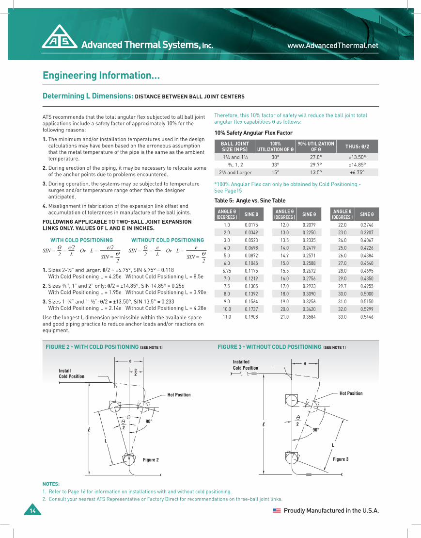
ATS recommends that the total angular flex subjected to all ball joint applications include a safety factor of approximately 10% for the following reasons:
1. The minimum and/or installation temperatures used in the design calculations may have been based on the erroneous assumption that the metal temperature of the pipe is the same as the ambient temperature.
2. During erection of the piping, it may be necessary to relocate some of the anchor points due to problems encountered.
3. During operation, the systems may be subjected to temperature surges and/or temperature range other than the designer anticipated.
4. Misalignment in fabrication of the expansion link offset and accumulation of tolerances in manufacture of the ball joints.
FOLLOWING APPLICABLE TO TWO-BALL JOINT EXPANSION LINKS ONLY. VALUES OF L AND E IN INCHES.
*100% Angular Flex can only be obtained by Cold Positioning -See Page15
1. Sizes 2-1⁄2” and larger: θ/2 = ±6.75°, SIN 6.75° = 0.118With Cold Positioning L = 4.25e Without Cold Positioning L = 8.5e
2. Sizes 3⁄4’’, 1” and 2” only: θ/2 = ±14.85°, SIN 14.85° = 0.256With Cold Positioning L = 1.95e Without Cold Positioning L = 3.90e
3. Sizes 1-1⁄4” and 1-1⁄2”: θ/2 = ±13.50°, SIN 13.5° = 0.233With Cold Positioning L = 2.14e Without Cold Positioning L = 4.28e
Use the longest L dimension permissible within the available space and good piping practice to reduce anchor loads and/or reactions on equipment.
NOTES:1. Refer to Page 16 for information on installations with and without cold positioning.2. Consult your nearest ATS Representative or Factory Direct for recommendations on three-ball joint links.
WITH COLD POSITIONING
SIN = ϴ2
= e/2L
L =SIN = ϴ
2
e/2Or
WITHOUT COLD POSITIONING
SIN = ϴ2
= eL
L =SIN = ϴ
2
eOr
Therefore, this 10% factor of safety will reduce the ball joint total angular flex capabilities θ as follows:
10% Safety Angular Flex Factor
BALL JOINT SIZE (NPS)
100% UTILIZATION OF θ
90% UTILIZATION OF θ THUS: θ/2
1 1⁄4 and 1 1⁄2 30° 27.0° ±13.50° 3⁄4, 1, 2 33° 29.7° ±14.85°
2 1⁄2 and Larger 15° 13.5° ±6.75°
Determining L Dimensions: DISTANCE BETWEEN BALL JOINT CENTERS
Table 5: Angle vs. Sine Table
ANGLE θ (DEGREES ) SINE θ
12.0 0.207913.0 0.225013.5 0.233514.0 0.241914.9 0.257115.0 0.258815.5 0.267216.0 0.275617.0 0.292318.0 0.309019.0 0.325620.0 0.342021.0 0.3584
ANGLE θ (DEGREES ) SINE θ
1.0 0.01752.0 0.03493.0 0.05234.0 0.06985.0 0.08726.0 0.1045
6.75 0.11757.0 0.12197.5 0.13058.0 0.13929.0 0.1564
10.0 0.173711.0 0.1908
ANGLE θ (DEGREES ) SINE θ
22.0 0.374623.0 0.390724.0 0.406725.0 0.422626.0 0.438427.0 0.454028.0 0.469529.0 0.485029.7 0.495530.0 0.500031.0 0.515032.0 0.529933.0 0.5446
FIGURE 2 - WITH COLD POSITIONING (SEE NOTE 1) FIGURE 3 - WITHOUT COLD POSITIONING (SEE NOTE 1)
Figure 2
With Cold Positioning(see Note 1)
l
L
Hot Position
InstallCold Position
e
90°2
e2
Figure 3
l
Hot Position
e
290°
L
InstalledCold Position
Without Cold Positioning(see Note 1)
1-800-443-9194 Advanced Thermal Systems, Inc.
Thermal Pak Flexible Ball Joints 12 15
Engineering Information…
FIGURE 4
l
Figure 4
A
L
B
A-B
Elbow
Elbow
FIGURE 5WITH COLD POSITIONING
With Cold Positioning
e1
γ
L1
1
Hot Position
Cold Position
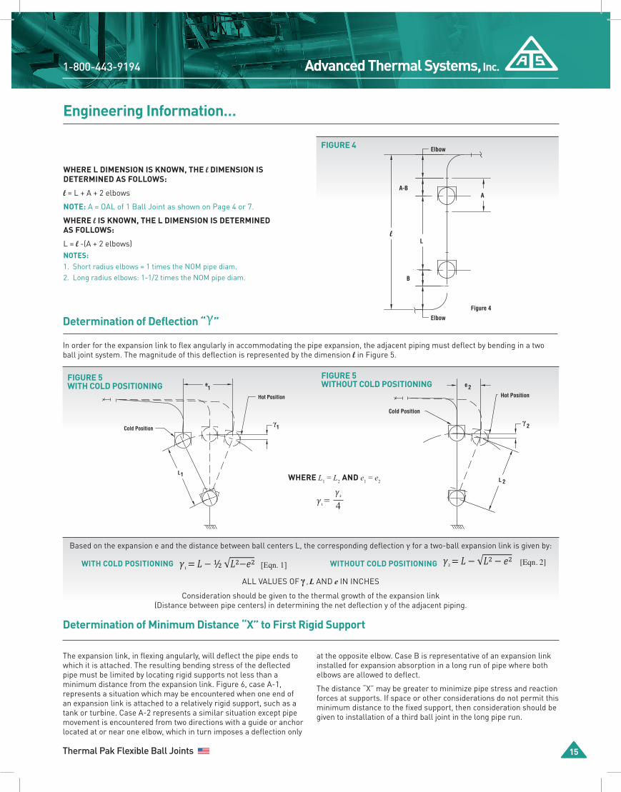
Determination of Deflection “γ”
In order for the expansion link to flex angularly in accommodating the pipe expansion, the adjacent piping must deflect by bending in a two ball joint system. The magnitude of this deflection is represented by the dimension l in Figure 5.
WITH COLD POSITIONING WITHOUT COLD POSITIONING
The expansion link, in flexing angularly, will deflect the pipe ends to which it is attached. The resulting bending stress of the deflected pipe must be limited by locating rigid supports not less than a minimum distance from the expansion link. Figure 6, case A-1, represents a situation which may be encountered when one end of an expansion link is attached to a relatively rigid support, such as a tank or turbine. Case A-2 represents a similar situation except pipe movement is encountered from two directions with a guide or anchor located at or near one elbow, which in turn imposes a deflection only
WHERE L DIMENSION IS KNOWN, THE l DIMENSION IS DETERMINED AS FOLLOWS:
l = L + A + 2 elbows
NOTE: A = OAL of 1 Ball Joint as shown on Page 4 or 7.
WHERE l IS KNOWN, THE L DIMENSION IS DETERMINEDAS FOLLOWS:
L = l -(A + 2 elbows)NOTES:1. Short radius elbows = 1 times the NOM pipe diam.2. Long radius elbows: 1-1/2 times the NOM pipe diam.
FIGURE 5WITHOUT COLD POSITIONING
Without Cold Positioning
e 2Hot Position
Cold Position
γ2
L 2
𝛾1 =𝛾2
4
WHERE L1 = L2 AND e1 = e2
Consideration should be given to the thermal growth of the expansion link (Distance between pipe centers) in determining the net deflection y of the adjacent piping.
Based on the expansion e and the distance between ball centers L, the corresponding deflection γ for a two-ball expansion link is given by:
ALL VALUES OF γ , L AND e IN INCHES
Determination of Minimum Distance “X” to First Rigid Support
at the opposite elbow. Case B is representative of an expansion link installed for expansion absorption in a long run of pipe where both elbows are allowed to deflect.
The distance “X” may be greater to minimize pipe stress and reaction forces at supports. If space or other considerations do not permit this minimum distance to the fixed support, then consideration should be given to installation of a third ball joint in the long pipe run.

www.AdvancedThermal.netAdvanced Thermal Systems, Inc.
16 12 Proudly Manufactured in the U.S.A.
Engineering Information…
WHERE e1 = e2
L1=L2
2
FIGURE 6, CASE A-1
Case A-1
X
γ
FIGURE 6, CASE A-2 FIGURE 6, CASE B
Case A-2
X
γ
Case B
2
X
X2
γ
X = MINIMUM DISTANCE BETWEEN RIGID SUPPORTS, FT.; D = PIPE OUTSIDE DIAM., INCHES; 𝛾 = DEFLECTION, INCHES.
Equations 3 and 4 are based on a cantilever beam analogy free to rotate using a modulus of elasticity of of steel is 29.9 E06 (29,900,000) psi and an allowable stress of 17,100 psi at temperatures up to 650ºF.
If the deflection of a two-joint expansion link system is too great and space or other factors do not permit increasing the link length "L" dimension, a third ball joint in the system should be considered. ATS's Engineering Department will provide recommendations for three-ball joint systems upon receipt of piping layout details and conditions. In addition to providing design service, including anchor calculations, support and guide recommendations, ATS will provide field inspection on request. Contact the nearest ATS Representative or factory direct for further information.
Positioning
The ATS Ball Joint expansion link may be installed exactly perpendicular to the pipe run (see Fig. 7B). This type installation is said to be "without cold positioning." In this case, only half of the total flexibility of the joints is utilized; however, it is not necessary to be concerned with contraction as a result of the operating temperature going below the installation temperature.
FIGURE 7 - A - WITH COLD POSITIONED FIGURE 7 - B - WITHOUT COLD POSITIONED
"COLD POSITIONING," i.e. prepositioning the link at installation with one-half the total expected expansion in the contracted position as In Fig.7A results in utilization of twice the angular flex available without cold positioning.
The expansion need not be the same on both sides of the expansion link. For example, if the expansion of the pipe on one side of the link is 4 inches and on the other side 2 inches, the expansion link may be cold-positioned by one-half of the total or 3 inches as in Fig. 8, Page17.
A - Cold Positioned
e 1Hot Position
Cold Position
θ
γ1
L 1
B -Without Cold Positioning
e 2
Hot Position
Cold Position
θ
Deflection
2
γ2
L 2
1-800-443-9194 Advanced Thermal Systems, Inc.
Thermal Pak Flexible Ball Joints 12 17
Engineering Information…
FIGURE 8
Figure 8
Cold PositionHot Position
e-Total = 6"
e 1 = 2"
e/2 = 3"
e 2 = 4"
FIGURE 9 - COLD POSITIONING
Figure 9 - Cold Positioning
L = 2.0'
Gap 1 3/4"
90°
5.61"
300°F20°F
80°F
Before Welding
A
B
A
AfterWelding
B
Figure 9 - Cold Positioning
L = 2.0'
Gap 1 3/4"
90°
5.61"
300°F20°F
80°F
Before Welding
A
B
A
AfterWelding
B
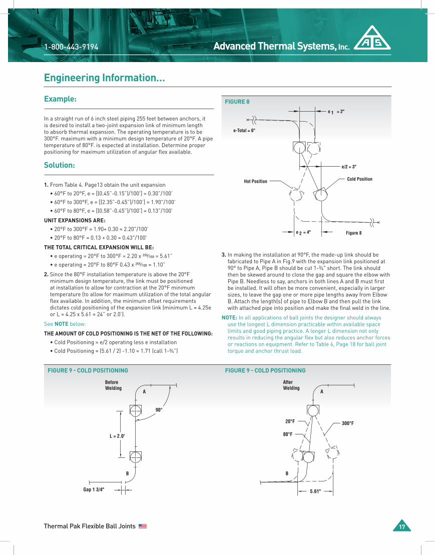
Example:
In a straight run of 6 inch steel piping 255 feet between anchors, it is desired to install a two-joint expansion link of minimum length to absorb thermal expansion. The operating temperature is to be 300°F. maximum with a minimum design temperature of 20°F. A pipe temperature of 80°F. is expected at installation. Determine proper positioning for maximum utilization of angular flex available.
Solution:
1. From Table 4. Page13 obtain the unit expansion
• 60°F to 20°F, e = [(0.45”-0.15”)/100'] = 0.30”/100’
• 60°F to 300°F, e = [(2.35”-0.45”)/100’] = 1.90"/100'
• 60°F to 80°F, e = [(0.58”-0.45”)/100’] = 0.13”/100’
UNIT EXPANSIONS ARE:• 20°F to 300°F = 1.90+ 0.30 = 2.20"/100'
• 20°F to 80°F = 0.13 + 0.30 = 0.43"/100'
THE TOTAL CRITICAL EXPANSION WILL BE:• e operating = 20°F to 300°F = 2.20 x 255⁄100 = 5.61”
• e operating = 20°F to 80°F 0.43 x 255⁄100 ≈ 1.10”
2. Since the 80°F installation temperature is above the 20°F minimum design temperature, the link must be positioned at installation to allow for contraction at the 20°F minimum temperature (to allow for maximum utilization of the total angular flex available. In addition, the minimum offset requirements dictates cold positioning of the expansion link (minimum L = 4.25e or L = 4.25 x 5.61 ≈ 24” or 2.0’).
See NOTE below:
THE AMOUNT OF COLD POSITIONING IS THE NET OF THE FOLLOWING:• Cold Positioning = e/2 operating less e installation
• Cold Positioning = (5.61 / 2) -1.10 ≈ 1.71 (call 1-3⁄4”)
3. In making the installation at 90°F, the made-up link should be fabricated to Pipe A in Fig.9 with the expansion link positioned at 90° to Pipe A, Pipe B should be cut 1-3⁄4" short. The link should then be skewed around to close the gap and square the elbow with Pipe B. Needless to say, anchors in both lines A and B must first be installed. It will often be more convenient, especially in larger sizes, to leave the gap one or more pipe lengths away from Elbow B. Attach the length(s) of pipe to Elbow B and then pull the link with attached pipe into position and make the final weld in the line.
NOTE: In all applications of ball joints the designer should always use the longest L dimension practicable within available space limits and good piping practice. A longer L dimension not only results in reducing the angular flex but also reduces anchor forces or reactions on equipment. Refer to Table 6, Page 18 for ball joint torque and anchor thrust load.
FIGURE 9 - COLD POSITIONING

www.AdvancedThermal.netAdvanced Thermal Systems, Inc.
18 12 Proudly Manufactured in the U.S.A.
Engineering Information…
ANCHOR THRUST LOAD
F = Anchor Thrust Load (lbs.)
T = Ball Joint Torque (ft. lbs.)
L = Distance between ball joint centers (ft.)
[Eqn. 5]F = 2TL
Ball Joint Torque “T” Thrust Load (Force at Anchor) "F"
Each ATS Thermal Pak Flexible Ball Joint is Flex Tested after completion of the assembly process. The ball joints are flexed through their full flex angle, and the force to move the ball is measured via a load cell and a digital readout, which are then verified and recorded. This production test ensures every ball joint is properly packed and the flex torque values are within the established range.
FIGURE 10
Figure 10
L
F
F
T
T
Table 6: Ball Joint Torque and Thrust Load
PIPE SIZE (NPS)
STEAM PRESSURE
(psig)
TYPICAL TORQUE,
T (ft.-lbs.)
3⁄4 - 1 1⁄2150 178300 226
2 - 2 1⁄2150 226300 262
3150 324
300 408
4150 604300 748
5150 882300 1,134
6150 1,880300 2,360
8150 2,930300 3,710
10150 5,050300 6,550
PIPE SIZE (NPS)
STEAM PRESSURE
(psig)
TYPICAL TORQUE,
T (ft.-lbs.)
12150 6,660300 8,520
14150 9,980300 12,260
16150 16,740300 20,580
18150 21,940300 26,980
20150 27,040300 33,280
24150 43,400300 51,800
30150 82,800300 99,600
NOTES: Flex torque values are based on a new ball joint. For design purposes a minimum safety factor of 50% is recommended. The use of metal compression seals (Field 5, Page 12) will produce more constant flex torque values over the life of the piping system.

1-800-443-9194 Advanced Thermal Systems, Inc.
Thermal Pak Flexible Ball Joints 12 19
ANSI B36.1 Carbon Steel Pipe Schedule
PIPE SIZE
(NPS)
OUTER DIAMETER
(in.)5 10 20 30 40 STD 60 80 E.H. 100 120 140 160 DBL.
E.H.
1⁄8 0.405 .035.138
.049.1863
.0682.447
.0682.447
.095.3145
.095.3145
1⁄4 0.540 .049.2570
.065.3297
.088.4248
.088.4248
.119.5351
.119.5351
3⁄8 0.675 .049.3276
.065.4235
.091.5676
.091.5676
.126.7388
.126.7388
1⁄2 0.840 .065.5383
.083.6710
.109.8510
.109.8510
.1471.088
.1471.088
.1871.304
.2941.714
3⁄4 1.050 .065.6838
.083.8572
.1131.131
.1131.131
.1541.474
.1541.474
.2181.937
.3082.441
1 1.315 .065.8678
.1901.404
.1331.679
.1331.679
.1792.172
.1792.172
.2502.844
.3583.659
1 1⁄4 1.660 .0651.107
.1091.806
.1402.273
.1402.273
.1912.997
.1912.997
.2503.765
.3825.214
1 1⁄2 1.900 .0651.274
.1092.638
.1452.718
.1452.718
.2003.631
.2003.631
.2814.859
.4006.408
2 2.375 .0651.604
.1092.638
.1543.653
.1543.653
.2185.022
.2185.022
.3437.444
.4369.029
2 1⁄2 2.875 .0832.475
.1203.531
.2035.793
.2035.793
.2767.661
.2767.661
.37510.01
.55213.70
3 3.500 .0833.029
.1204.332
.2167.576
.2167.576
.30010.25
.30010.25
.43714.32
.60018.58
3 1⁄2 4.000 .0833.472
.1204.973
.2269.109
.2269.109
.31812.51
.31812.51
.63622.85
4 4.500 .0833.915
.1205.613
.23710.79
.23710.79
.28112.66
.33714.98
.33714.98
.43719.01
.53122.51
.67427.54
4 1⁄2 5.000 .24712.53
.35517.61
.71032.53
5 5.563 .1096.349
.1347.770
.25814.62
.25814.62
.37520.78
.37520.78
.50027.04
.62532.96
.75038.55
6 6.625 .1097.585
.1349.289
.28018.97
.28018.97
.43228.57
.43228.57
.56236.39
.71845.30
.86453.16
7 7.625 .30123.57
.50038.05
.87563.08
8 8.625 .1099.914
.14813.40
.25022.36
.27724.70
.32228.55
.32228.55
.40635.64
.50043.39
.50043.39
.59350.87
.71860.63
.81267.76
.90674.69
.87572.42
9 9.625 .34233.90
.50048.72
10 10.750 .13415.19
.16518.65
.25028.04
.30734.24
.36540.48
.36540.48
.50054.74
.59364.33
.50054.74
.71876.93
.84389.20
1.000104.1
1.125115.7
11 11.750 .37545.55
.50060.07
12 12.750 .15621.07
.18024.20
.25033.38
.33043.77
.40653.53
.37549.56
.56273.16
.68788.51
.50065.42
.843107.2
1.000125.5
1.125139.7
1.312160.3
14 14.000 .15623.06
.25036.71
.31245.68
.37554.57
.43763.37
.37554.57
.59384.91
.750106.1
.50072.09
.937130.7
10.93150.7
1.250170.2
1.406189.1
16 16.000 .16527.90
.25042.05
.31252.36
.37562.58
.50082.77
.37562.58
.656107.5
.843136.5
.50082.77
1.031164.8
1.218192.3
1.437223.5
1.593245.1
18 18.000 .16531.43
.25047.39
.31259.03
.43782.06
.562104.8
.37570.59
.750138.2
.937170.8
.50093.45
1.156208.0
1.375244.1
1.562274.2
1.781308.5
20 20.000 .18839.78
.25052.73
.37578.60
.500104.1
.593122.9
.37578.60
.812166.4
1.031208.9
.500104.1
1.280256.1
1.500296.4
1.750341.1
1.968379.0
24 24.000 .21855.37
.25063.41
.37594.62
.562140.8
.687171.2
.37594.62
.968238.1
1.218296.4
.500125.5
1.531367.1
1.812429.4
2.062483.1
2.343541.9
www.AdvancedThermal.netAdvanced Thermal Systems, Inc.
Return for Credit
No returns for credit shall be accepted unless sellers permission has been obtained in each case in advance. Only sizes and designs taken from the sellers standard catalog line, which are in active demand, can be accepted for credit. Obsolete or specially manufactured products cannot be accepted for return or credit. For further information pertaining to Advanced Thermal Systems, Inc. Return Policy, please contact Customer Service.
Replacement Guarantee
In addition, ATS guarantees the satisfactory performance of ATS thermal Pak Flexible Ball Joint for a period of five years from date of shipment. Provided only, that the ATS Thermal Pak Flexible Ball Joints are installed and operated in accordance with ATS prescribed standards. ATS will either replace or repair, without charge, FOB ATS factory any Thermal Pak Flexible Ball Joint, which fails to give five years’ service under these prescribed conditions.
5-Year Leak-Free Warranty
For Application to 400 psig - 800° F
In the event of leakage in the ATS Thermal Pak Flexible Ball Joint spare packing plugs will be furnished at no charge for a period of 5-years from the date of the original shipment date.
Warranty Terms
Advanced Thermal Systems, Inc. Thermal Pak Flexible Ball Joints are sold subject to the mutual agreement that they are warranted by ATS to be free from defects in material and workmanship but ATS's liability and the buyer's exclusive remedy shall be limited to replacement without charge, at ATS’s factory of any material defects which become apparent within one year of the date of shipment, and which shall be determined to be defective by ATS upon their return to the factory, freight prepaid. ATS may opt to provide a refund of the purchase price and that ATS shall have no liability for damages of any kind, direct or indirect, arising from an installation and/or use of any material and by accepting the material the buyer will assume all liability for any damages, direct or consequential, which may result from issue or misuse.
ATS Thermal Pak Flexible Ball Joint5-Year Warranty And Replacement Guarantee
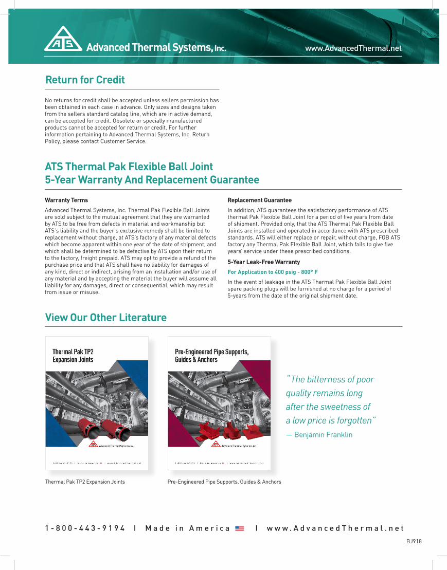
View Our Other Literature
Thermal Pak TP2 Expansion Joints
“ The bitterness of poor quality remains long after the sweetness of a low price is forgotten”— Benjamin Franklin
Pre-Engineered Pipe Supports, Guides & Anchors
1 - 8 0 0 - 4 4 3 - 9 1 9 4 I M a d e i n A m e r i c a 12 I w w w . A d v a n c e d T h e r m a l . n e t
BJ918