dodge ram adjustable ball joints installation instructions
TRANSCRIPT
THE INFORMATION CONTAINED IN THIS DRAWING IS
THE SOLE PROPERTY OF SYNERGY MFG. ANY
REPRODUCTION IN PART OR WHOLE WITHOUT THE
WRITTEN PERMISSION OF SYNERGY MFG IS
PROHIBITIED.
Revisions
Rev. Description Date Approved
A Initial Draft 11/2/17 A.S.
B Revised Per ECO 18-096 9/11/18 A.S.
Dodge Ram Adjustable Ball Joints
Installation Instructions
Applications: 2003-2013 Dodge Ram 2500 4X4
2003-2012 Dodge Ram 3500 4X4
2006-2008 Dodge Ram 1500 4X4 Mega Cab
TITLE:
DODGE RAM 03-13 ADJUSTABLE BALL
JOINT INSTALL INSTRUCTIONS
SIZE DWG NO:
REV
A
4123-INST B
SCALE: N/A PAGE 1 OF 16
DODGE RAM 03-13 ADJUSTABLE BALL JOINT
INSTALLATION INSTRUCTIONS
DOC NO. 4123-INST PAGE 2 OF 16
Thank you for purchasing the best aftermarket products available for your vehicle. We strongly feel that the
parts you are about to install should meet or exceed your expectations for performance. Proper assembly is
critical to the performance of these components and the vehicle as a whole. Please take the time to carefully
read these instructions and familiarize yourself with the installation procedure before working on your
vehicle. If you have any questions PLEASE contact Synergy Manufacturing BEFORE beginning
installation. Thanks again for supporting Synergy – enjoy the performance benefits of the best aftermarket
products available for your vehicle!
Synergy Manufacturing
Phone: (805) 242-0397
Email: [email protected]
Now for the lawyer part:
Modifying or otherwise altering vehicle components may cause the vehicle to handle differently than
originally designed. It is the driver’s responsibility to familiarize themselves with the performance and
handling characteristics of the modified vehicle. Vehicles with larger diameter than stock tires must be
driven carefully and cannot be expected to perform as stock or meet OEM performance with regard to
handling, braking or crash performance. Ensure all replacement components are compatible with vehicle
capacities so as not to overload components, especially tires. It is up to the individual to ensure that the
vehicle and all components are compatible with the intended vehicle use, including load ratings, road
conditions, and driver abilities. Thorough and frequent vehicle inspections are recommended to ensure a
safe and reliable state of readiness, especially after off-highway use.
DODGE RAM 03-13 ADJUSTABLE BALL JOINT
INSTALLATION INSTRUCTIONS
DOC NO. 4123-INST PAGE 3 OF 16
PARTS LIST 4123 Dodge Ram 4X4 Ball Joints
QTY Part Number Description
2 412301-02 Adjustable/Rebuildable Lower Ball Joint
2 412301-01 Upper Ball Joint
1 412301-HDW Hardware Kit
1 412303-04-PL Ball Joint Adjuster Wrench
GENERAL NOTES • These instructions are also available on our website; www.synergymfg.com. Check
the website before you begin for any updated instructions and additional photos and
videos for your reference.
• Worn front end components can quickly wear out other components. When replacing
ball joints, check the condition of the tie rod ends in the steering and the track bar and
suspension bushings, especially if ‘death wobble’ was ever experienced. Replace all
worn components all at once.
• These Synergy ball joints are designed as a lifetime part. As they wear, the joint can
be adjusted to accommodate for this wear. This adjustment can be performed with the
vehicle on the ground without removing any parts from the vehicle. If no more
adjustment is possible, the joints can be re-built without removing the ball joint body
from the axle housing.
• Rebuild kits are available from Synergy Mfg.
• While these ball joints are designed as a lifetime part, they are not maintenance free.
The joints require lubrication with fresh grease occasionally. We recommend re-
greasing the joints after every 20,000 road miles. If harsh conditions are encountered,
such as a dusty, salty, or wet environment, then we recommend re-greasing the joints
more frequently.
• Ball joint installation should be done by qualified professionals. Incorrect ball joint
installation can cause severe problems and safety issues.
• The upper ball joints are a plunge type – the stud should move freely up and down.
This is normal.
• These Synergy ball joints have a break in period. This can be from a couple hundred
to a couple thousand miles, depending on the vehicle and driving conditions. Until the
joints have properly broken in, the steering can feel ‘tight’ and the vehicle will not
return to center well. This is a typical characteristic of metal on metal joints.

DODGE RAM 03-13 ADJUSTABLE BALL JOINT
INSTALLATION INSTRUCTIONS
DOC NO. 4123-INST PAGE 4 OF 16
TOOLS NEEDED • Ball Joint Press
• Retaining Ring Pliers
• Basic Hand Tools (5mm allen wrench, 18mm wrenches and sockets, 30mm wrench or
socket, 21mm wrench or socket)
• ¼ Drive Torque Wrench (For preload adjustment)
ESTIMATED INSTALLATION TIME
4-6 Hours
LOWER BALL JOINT OVERVIEW
1. These ball joints are adjustable for preload and are rebuildable. Figure 1 identifies the
components of the ball joint and the assembly order.
Figure 1. Ball Joint Components and Assembly Order
2. We recommend installing the joints assembled, but the joints may be disassembled for
installation. This eliminates the need for special fittings to press in the joint. The joint
can then be re-assembled on the vehicle.
3. If the joint is to be disassembled for installation, it is important to keep all the parts of
specific joints together. We recommend only disassembling one joint at a time or
keeping them in separate left/right trays or boxes. See separate instructions for
Synergy Rebuild Kit Part Number 4123-1000 for disassembly and re-assembly.
BODY PRELOAD WASHER BEARING DUST BOOT CAP LOCK TAB WASHER STUD ROLL PIN
DODGE RAM 03-13 ADJUSTABLE BALL JOINT
INSTALLATION INSTRUCTIONS
DOC NO. 4123-INST PAGE 5 OF 16
INSTALLATION 1. Park the truck on a flat, level surface, or safely raise the vehicle on a lift. Chock the
rear wheels, make sure the vehicle is in park or in gear, and set the parking brake.
Raise the front end, place the front axle housing on jack stands and remove the front
wheels.
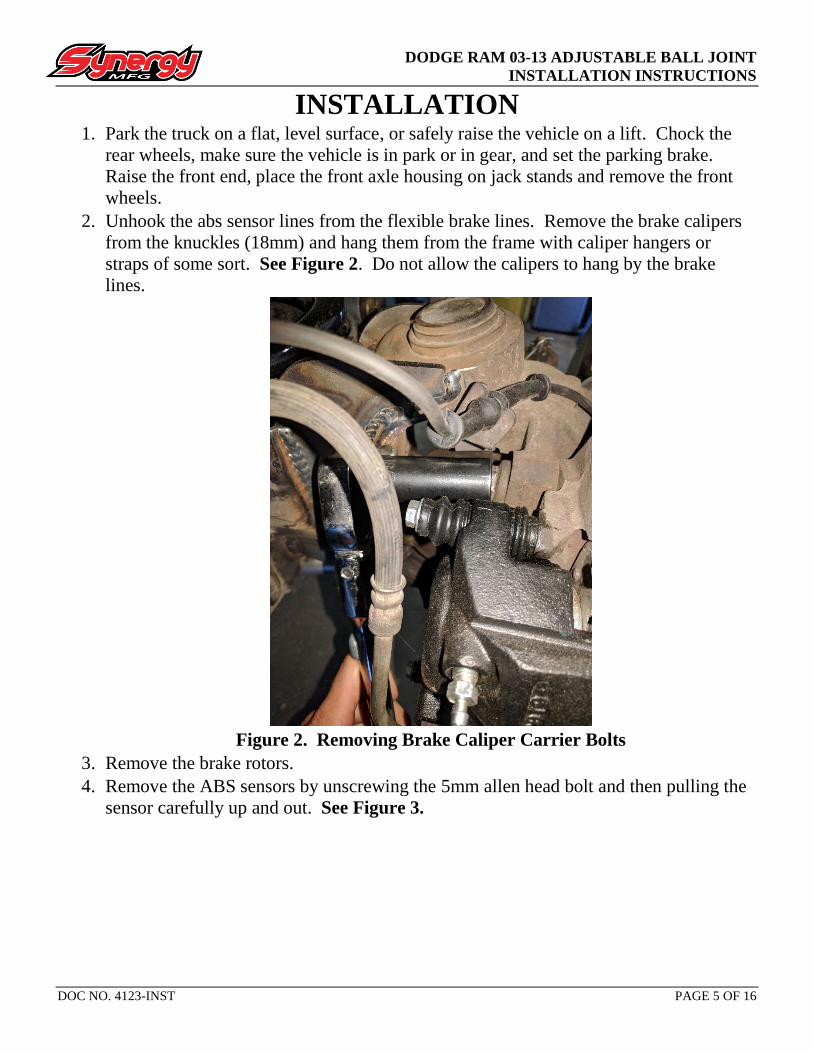
2. Unhook the abs sensor lines from the flexible brake lines. Remove the brake calipers
from the knuckles (18mm) and hang them from the frame with caliper hangers or
straps of some sort. See Figure 2. Do not allow the calipers to hang by the brake
lines.
Figure 2. Removing Brake Caliper Carrier Bolts
3. Remove the brake rotors.
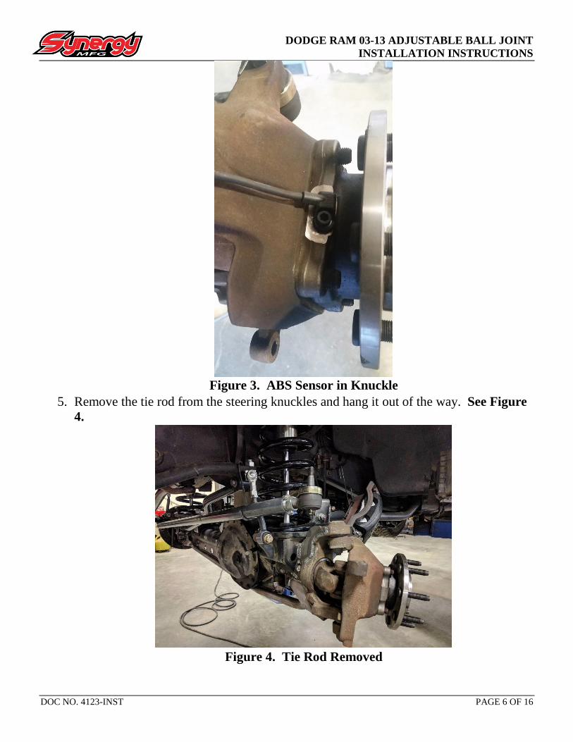
4. Remove the ABS sensors by unscrewing the 5mm allen head bolt and then pulling the
sensor carefully up and out. See Figure 3.
DODGE RAM 03-13 ADJUSTABLE BALL JOINT
INSTALLATION INSTRUCTIONS
DOC NO. 4123-INST PAGE 6 OF 16
Figure 3. ABS Sensor in Knuckle
5. Remove the tie rod from the steering knuckles and hang it out of the way. See Figure
4.
Figure 4. Tie Rod Removed
DODGE RAM 03-13 ADJUSTABLE BALL JOINT
INSTALLATION INSTRUCTIONS
DOC NO. 4123-INST PAGE 7 OF 16
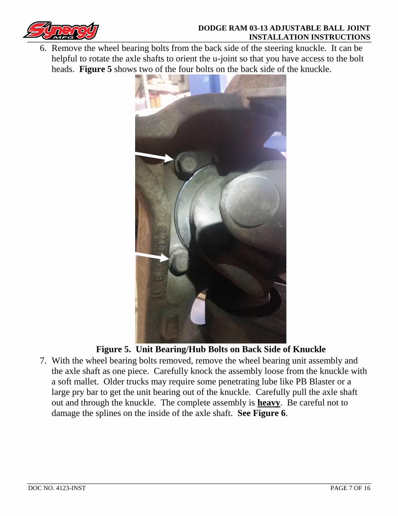
6. Remove the wheel bearing bolts from the back side of the steering knuckle. It can be
helpful to rotate the axle shafts to orient the u-joint so that you have access to the bolt
heads. Figure 5 shows two of the four bolts on the back side of the knuckle.
Figure 5. Unit Bearing/Hub Bolts on Back Side of Knuckle
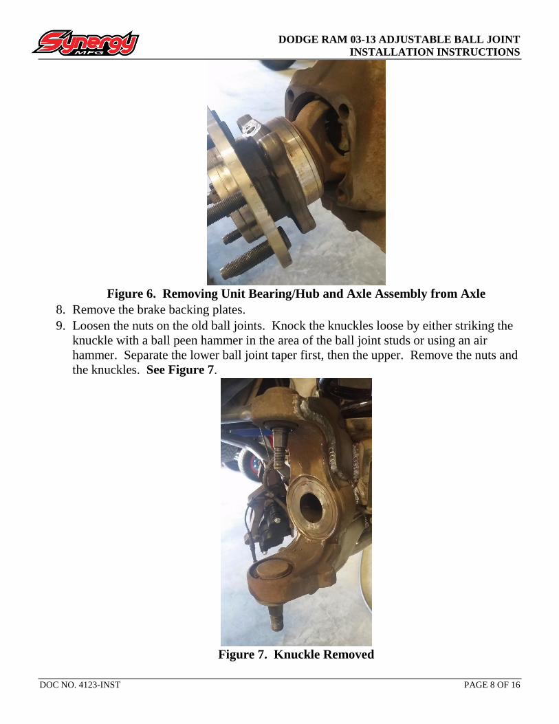
7. With the wheel bearing bolts removed, remove the wheel bearing unit assembly and
the axle shaft as one piece. Carefully knock the assembly loose from the knuckle with
a soft mallet. Older trucks may require some penetrating lube like PB Blaster or a
large pry bar to get the unit bearing out of the knuckle. Carefully pull the axle shaft
out and through the knuckle. The complete assembly is heavy. Be careful not to
damage the splines on the inside of the axle shaft. See Figure 6.
DODGE RAM 03-13 ADJUSTABLE BALL JOINT
INSTALLATION INSTRUCTIONS
DOC NO. 4123-INST PAGE 8 OF 16
Figure 6. Removing Unit Bearing/Hub and Axle Assembly from Axle
8. Remove the brake backing plates.
9. Loosen the nuts on the old ball joints. Knock the knuckles loose by either striking the
knuckle with a ball peen hammer in the area of the ball joint studs or using an air
hammer. Separate the lower ball joint taper first, then the upper. Remove the nuts and
the knuckles. See Figure 7.
Figure 7. Knuckle Removed

DODGE RAM 03-13 ADJUSTABLE BALL JOINT
INSTALLATION INSTRUCTIONS
DOC NO. 4123-INST PAGE 9 OF 16
10. Remove c-clip from lower ball joints. Remove dust boots from all the ball joints and
wipe up all old grease. Press out the old ball joints. The lower ball joints are pressed
out ‘down’ and the uppers are pressed out ‘up’. See Figures 8 and 9.
Figure 8. Pressing Out Lower Ball Joint Figure 9. Pressing Out Upper Ball Joint
11. Inspect knuckle tapers and inner c bores. Ensure they are not deformed and are clean
and free of burrs. Damaged parts should be replaced or repaired as necessary.
12. Remove the dust boots from the Synergy ball joints prior to installation so that they are
not damaged during installation.
13. The lower ball joints should be pressed in assembled, but if the correct tools are not
available then you may take the ball joint apart and press in just the body. It is
important that the press adapters do not rest on the locking tabs on the outside of the
cap. If the press adapters are too large, they may damage the locking tabs machined
into the cap. Most ball joint presses should have an adapter that fits the lower ball
joint correctly.
14. Orient the Synergy lower ball joints - Depending on the wheel offset, axle trusses and
gussets, axle shaft size and other factors, the orientation of the zerk will need to be
decided by the installer. We recommend orienting the zerk fitting so that it is pointing
towards the front of the vehicle, slightly toward center. See Figure 10.

DODGE RAM 03-13 ADJUSTABLE BALL JOINT
INSTALLATION INSTRUCTIONS
DOC NO. 4123-INST PAGE 10 OF 16
Figure 10. Lower Ball Joint Orientation
15. Once the lower ball joints are correctly oriented, press the joints (or housings if
disassembled) into the axle housing. It is critical that the body is pressed in evenly and
smoothly. Grease is not necessary but can be used if desired. The joint must sit flat
and flush against the lower surface of the inner c. See Figure 11.
Figure 11. Lower Ball Joint Body Pressed In
16. Press the upper ball joints into the axle housing. It is critical that the body is pressed in
evenly and smoothly. Grease is not necessary but can be used if desired. The press
tool should sit on the lip on the outside of the ball joint body. The joint must sit flat
and flush against the upper surface of the inner c. See Figure 12.
FRONT OF VEHICLE

DODGE RAM 03-13 ADJUSTABLE BALL JOINT
INSTALLATION INSTRUCTIONS
DOC NO. 4123-INST PAGE 11 OF 16
Figure 12. Upper Ball Joint Pressed In
17. If the lower ball joints were pressed in assembled, bend out the locking tabs that
interface with the cap out so that the cap may be rotated. If the lower ball joints were
disassembled for installation, re-assemble the joints.
18. Install the zerk fittings and dust boots onto the ball joints. Install circlip on lower ball
joints.
19. Note the orientation of the cotter pin holes in the ball joint pins. We recommend
aligning the cotter pin holes so that they are perpendicular to the axle, aligned front to
back on the vehicle. See Figure 13. If the cotter pin holes need to be relocated, spin
the ball studs with a pin through the cotter pin hole. This will make cotter pin
installation easier.

DODGE RAM 03-13 ADJUSTABLE BALL JOINT
INSTALLATION INSTRUCTIONS
DOC NO. 4123-INST PAGE 12 OF 16
Figure 13. Cotter Pins Aligned Front to Back
20. Install steering knuckles. Tighten lower ball joint nut slightly (no more than 50 lb-ft).
21. Re-install abs line clips under upper ball joint nut if so equipped. Torque upper ball
joint castle nuts to 70 lb-ft.
22. Torque lower ball joint castle nuts to 150 lb-ft.
23. Rotate the knuckles from lock to lock by hand. They should be stiff, but able to rotate
by hand. Ensure there are no clearance issues anywhere. Potential problems may arise
with worn knuckles; the lower ball joint taper could sit too deep in the knuckle and
cause the knuckle to interfere with the ball joint or inner C. If this is the case, the
vehicle will need new knuckles.
24. Install cotter pins. If the castle nut slots do not line up with the cotter pin holes,
continue to tighten the castle nuts until they align. Never loosen a castle nut to align
the cotter pin. If the cotter pin hole is above the top of the castle nut, remove the castle
nut and place a washer under the castle nut to make sure the pin engages with the nut.
Usually this is an indication that the knuckle taper has been worn out and the knuckles
should be replaced. See Figure 14.

DODGE RAM 03-13 ADJUSTABLE BALL JOINT
INSTALLATION INSTRUCTIONS
DOC NO. 4123-INST PAGE 13 OF 16
Figure 14. Cotter Pin Installed
25. Set preload on the lower ball joints. See the ADJUSTING LOWER BALL JOINT
PRELOAD section on page 15.
26. With the joints preloaded, bend down two tabs from the lock ring into the cap. Be sure
the tabs bent down will be accessible when the vehicle is re-assembled and back on the
ground. If the tabs do not align with slots on the cap be sure to tighten the cap in order
to make them align. Do not loosen the cap to align the tabs.
Figure 15. Tabs Bent Into Cap
27. Re-install brake backing plates, being sure to orient them correctly. Insert two of the
unit bearing bolts through the knuckle to hold the backing plate in place.
28. Re-install the unit bearing/hub/axle shaft assembly, being very careful when installing
the axle shaft to ensure the splines line up in the differential and not to damage the
DODGE RAM 03-13 ADJUSTABLE BALL JOINT
INSTALLATION INSTRUCTIONS
DOC NO. 4123-INST PAGE 14 OF 16
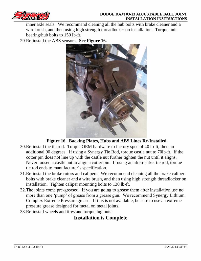
inner axle seals. We recommend cleaning all the hub bolts with brake cleaner and a
wire brush, and then using high strength threadlocker on installation. Torque unit
bearing/hub bolts to 150 lb-ft.
29. Re-install the ABS sensors. See Figure 16.
Figure 16. Backing Plates, Hubs and ABS Lines Re-Installed
30. Re-install the tie rod. Torque OEM hardware to factory spec of 40 lb-ft, then an
additional 90 degrees. If using a Synergy Tie Rod, torque castle nut to 70lb-ft. If the
cotter pin does not line up with the castle nut further tighten the nut until it aligns.
Never loosen a castle nut to align a cotter pin. If using an aftermarket tie rod, torque
tie rod ends to manufacturer’s specification.
31. Re-install the brake rotors and calipers. We recommend cleaning all the brake caliper
bolts with brake cleaner and a wire brush, and then using high strength threadlocker on
installation. Tighten caliper mounting bolts to 130 lb-ft.
32. The joints come pre-greased. If you are going to grease them after installation use no
more than one ‘pump’ of grease from a grease gun. We recommend Synergy Lithium
Complex Extreme Pressure grease. If this is not available, be sure to use an extreme
pressure grease designed for metal on metal joints.
33. Re-install wheels and tires and torque lug nuts.
Installation is Complete

DODGE RAM 03-13 ADJUSTABLE BALL JOINT
INSTALLATION INSTRUCTIONS
DOC NO. 4123-INST PAGE 15 OF 16
ADJUSTING LOWER BALL JOINT PRELOAD 1. It is important to periodically check the lower ball joints for play. The easiest way to
check for a loose joint is to place a jack under the axle housing on one side. Raise the
jack so that the tire is just off the ground. Place a jack stand just behind the axle
housing, next to the tire. Using a prybar or other lever, try and ‘push’ the steering
knuckle upwards. See Figure 17. Per factory spec, there is up to .090” of vertical play
allowable. We recommend keeping this number as close to zero as possible.
Figure 17. Checking Preload
2. If there is movement found in step one, or upon initial installation, the joints must be
adjusted. In order to adjust the joint you must first bend back any tabs on the lock
washer that are engaged with the slots on the cap. See Figure 18.
Figure 18. Bending Locking Tabs Back

DODGE RAM 03-13 ADJUSTABLE BALL JOINT
INSTALLATION INSTRUCTIONS
DOC NO. 4123-INST PAGE 16 OF 16
3. We highly recommend setting preload by using a ¼” drive torque wrench, see step 4.
If no torque wrench is available, tighten the joint until there is no vertical play while
using a large prybar to pry up on the steering knuckle as shown in Figure 17.
4. With the tabs bent out of the way, slowly turn the cap clockwise (threads are right
hand) using the provided adjuster tool and a ¼” drive torque wrench. Tighten the
joints until 120lb-in (10lb-ft) is shown on the torque wrench. Our adjustment torque
spec is the torque at the wrench, not at the joint (due to the included crows foot type
adapter). It is important that the torque wrench is oriented perpendicular to the joint,
as seen in Figure 19. Figure 20 shows the wrench oriented incorrectly, at a 90 degree
angle to the joint. Once the torque spec is achieved, bend the tabs from the lock ring to
engage with the cap. We recommend at least two tabs bent into the cap. Only bend up
locking tabs that are accessible so that the joint may be adjusted again in the future.
Figure 19. Correct Wrench Orientation Figure 20. Incorrect Wrench Orientation