thermal engineering lab syllabus
TRANSCRIPT

3 THERMAL ENGINEERING LAB MANUAL
THERMAL ENGINEERING LAB SYLLABUS
Exp. No.
Experiment Page
1 VALVE TIMING DIAGRAM 6
2 PORT TIMING DIAGRAM 10
3 IC ENGINE PERFORMANCE TEST FOR
4 STROKE S I ENGINE
14
4 IC ENGINEPERFORMANCE TEST FOR
2 STROKE S I ENGINE
20
5 IC ENGINE MORSE REATRDATION
MOTORING TESTS
25
6 I C ENGINE HEAT BALANCE -S I ENGINE 32
7 I C ENGINE ECONOMICAL SPEED TESTONS I
ENGINE
38
8 HEAT BALANCE TEST ON DIESEL ENGINE 44
9 HEAT BALANCE TEST ON DIESEL ENGINE 51
10 PERFORMANCE TEST ON VARIABLE
COMPRESSION RATIO ENGINE
56
11 VOLUMETRIC EFFICIENCY OF
A RECIPROCATING AIR COMPRESSOR
63
12 ASSEMBLYING AND DIS ASSEMBLYING IC
ENGINE
69
13 STUDY OF BOILERS 74
Content Beyond Syllabi
1 STUDY OF TURBO JET
2 PERFORMANCE OF CENTRIFUGAL AND AXIAL
FLOW COMPRESSORS
MECHANICAL ENGINEERING DEPARTMENT
4 THERMAL ENGINEERING LAB MANUAL
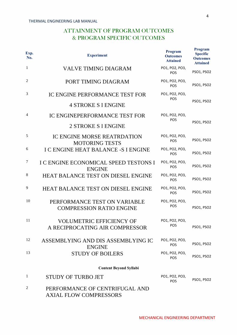
ATTAINMENT OF PROGRAM OUTCOMES
& PROGRAM SPECIFIC OUTCOMES
Exp. No.
Experiment Program Outcomes Attained
Program Specific
Outcomes Attained
1 VALVE TIMING DIAGRAM PO1, PO2, PO3, PO5 PSO1, PSO2
2 PORT TIMING DIAGRAM PO1, PO2, PO3, PO5 PSO1, PSO2
3 IC ENGINE PERFORMANCE TEST FOR
4 STROKE S I ENGINE
PO1, PO2, PO3, PO5
PSO1, PSO2
4 IC ENGINEPERFORMANCE TEST FOR
2 STROKE S I ENGINE
PO1, PO2, PO3, PO5
PSO1, PSO2
5 IC ENGINE MORSE REATRDATION
MOTORING TESTS
PO1, PO2, PO3, PO5 PSO1, PSO2
6 I C ENGINE HEAT BALANCE -S I ENGINE PO1, PO2, PO3, PO5 PSO1, PSO2
7 I C ENGINE ECONOMICAL SPEED TESTONS I
ENGINE
PO1, PO2, PO3, PO5 PSO1, PSO2
8 HEAT BALANCE TEST ON DIESEL ENGINE PO1, PO2, PO3, PO5 PSO1, PSO2
9 HEAT BALANCE TEST ON DIESEL ENGINE PO1, PO2, PO3, PO5 PSO1, PSO2
10 PERFORMANCE TEST ON VARIABLE
COMPRESSION RATIO ENGINE
PO1, PO2, PO3, PO5
PSO1, PSO2
11 VOLUMETRIC EFFICIENCY OF
A RECIPROCATING AIR COMPRESSOR
PO1, PO2, PO3, PO5
PSO1, PSO2
12 ASSEMBLYING AND DIS ASSEMBLYING IC
ENGINE
PO1, PO2, PO3, PO5 PSO1, PSO2
13 STUDY OF BOILERS PO1, PO2, PO3, PO5 PSO1, PSO2
Content Beyond Syllabi
1 STUDY OF TURBO JET PO1, PO2, PO3, PO5 PSO1, PSO2
2 PERFORMANCE OF CENTRIFUGAL AND
AXIAL FLOW COMPRESSORS
MECHANICAL ENGINEERING DEPARTMENT
5 THERMAL ENGINEERING LAB MANUAL
THERMAL ENGINEERING LAB
OBJECTIVE:
In this laboratory, students will have the opportunity to study the working principle of IC
engines (both SI and CI engines), performance and characteristics in terms of heat balancing,
economical speed variations, air fuel ratio influence on the engine to reinforce classroom theory by
having the student perform required tests, analyze subsequent data, and present the results in a
professionally prepared report.
The machines and equipment used to determine experimental data include cut models of
4stroke diesel engine, 2stroke petrol engine, 4stroke and two stroke petrol engines with required
specifications, Multi cylinder SI engine, Single cylinder Diesel engine for performance and speed test
which is suitable to tests on variable compression ratios.
OUTCOMES: Upon the completion of Mechanicsl of Solids practical course, the student will be able to:
1. Determine the valve timing diagram of SI engine & CI engine.
2. Analyze the influence of variations in TDC and BDC operations
3. Calculate the IP,BP, brake thermal efficiency.
4. Calculate & Compare the performance characteristics.
5. Experiment on IC engine load variations with Air fuel ratio.
6. Apply the concept of Morse test on SI engine.(multi cylinder).
7. Analyse the efficiency of reciprocating air compressor
8. Determine the principle of various parameters in boilers.
MECHANICAL ENGINEERING DEPARTMENT
6 THERMAL ENGINEERING LAB MANUAL
EXPERIMENT NO: 1
VALVE TIMING DIAGRAM
MECHANICAL ENGINEERING DEPARTMENT
7 THERMAL ENGINEERING LAB MANUAL
AIM:
The experiment is conducted to
Determine the actual valve timing for a 4-stroke diesel engine and hence
draw the diagram.
DATA:ENGINE- 4stroke, single cylinder, constant speed, and watercooled
vertical diesel engine, 5BHP, and 1500rpm.
THEORY:
In a four stroke engine opening and closing of valves and fuel injection do
not take place exactly at the end of dead center positions. The valves open slightly
earlier and close after that respective dead center position. The injection (ignition)
also occurs prior to the full compression and the piston reaches the dead Centre
position. All the valves operated at some degree on either side in terms of crank
angles from dead center position.
INLET VALVE:
During the suction stroke the inlet valve must be open to admit charge into
the cylinder, the inlet valve opens slightly before the piston starts downward
on the suction stroke.
The reason that the inlet valve is open before the start of suction stroke is that the
valve is necessary to permit this valve to be open and close slowly to provide
quite operations under high speed condition.
INLET VALVE OPENS (IVO):
It is done at 10to 250in advance of TDC position.
INLET VALVE CLOSES (IVC):
It is done at 25 to 500after BDC position.
EXHAUST VALVE:
As the piston is forced out on the outstroke by the expanding gases, it has been
found necessary to open the exhaust valve before the piston reaches the end of the
stroke. By opening the exhaust valve before the piston reaches the end of its own
power stroke, the gases have an outlet for expansion and begin to rush out of their
own accord. This removes the greater part of the burnt gases reducing the amount
of work to be done by the piston on its return stroke.
MECHANICAL ENGINEERING DEPARTMENT
8 THERMAL ENGINEERING LAB MANUAL
EXHAUST VALVE OPENS (EVO):
It is done at 30 to 500 in advance of BDC position.
EXHAUST VALVE CLOSES (EVC): It is done at
10 to 150 after the TDC position.
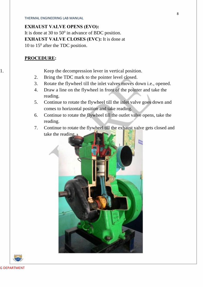
PROCEDURE:
1. Keep the decompression lever in vertical position.
2. Bring the TDC mark to the pointer level closed.
3. Rotate the flywheel till the inlet valves moves down i.e., opened.
4. Draw a line on the flywheel in front of the pointer and take the
reading.
5. Continue to rotate the flywheel till the inlet valve goes down and
comes to horizontal position and take reading.
6. Continue to rotate the flywheel till the outlet valve opens, take the
reading.
7. Continue to rotate the flywheel till the exhaust valve gets closed and
take the reading.
G DEPARTMENT

9 THERMAL ENGINEERING LAB MANUAL
4 Stroke Diesel Engine
OBSERVATIONS:
Sl. No. Valve Position Arc Length, S
Angle ‘θ’indegrees
cm Mm
1 TDC - Inlet Valveopen
2 BDC - Inlet ValveClose
3 TDC - ExhaustValve Open
4 BDC - ExhaustValve Close
CALCULATIONS:
1. Diameter of the flywheel, D
2.
D =
2. Angle ‘θ’ in degrees,
θ =
Where,
S = Arc length, mm
RESULT:
Valve Timing diagram is drawn PRE LAB QUESTIONS
1. Differentiate valve and port? 2. Define valve timing?. 3. Explain the importance of valve timing? 4. Define mechanism of valve operation? 5. Define the cam mechanism in IC engine? 6. Define crank mechanism?
1.17 POST LAB QUESTIONS
1.What are the position of inlet vale opening and closing? 2.What are the exhaust valve opening and closing positions? 3.Indicate the ignition period in the diagram?
MECHANICAL ENGINEERING DEPARTMENT
10 THERMAL ENGINEERING LAB MANUAL
EXPERIMENT NO: 2
PORT TIMING DIAGRAM
MECHANICAL ENGINEERING DEPARTMENT

11 THERMAL ENGINEERING LAB MANUAL
AIM:
The experiment is conducted to
Determine the actual PORT timing for a 2-stroke Petrol engine and
hence draw the diagram.
DATA:Engine: 2stroke single cylinder, constant speed, water cooled, vertical
diesel engine, 5 BHP, 1500rpm.
THEORY: Here in this type of engine ports which take charges and remove
exhaust are in the cylinder itself. By virtue of piston when the piston moves
inside the cylinder it closes and opens ports. Here in this type of engine (two
strokes) one revolution of crank shaft complete one cycle.
INLET PORT:
1. It is uncovered 45 to 500in advance of TDC.
2.It is covered 40 to 450after BDC.
EXHAUST PORT:
1.It is uncovered 40 to 450in advance of BDC.
2.It is covered 40 to 550after the TDC.
TRANSFER PORT:
1.It is uncovered 35 to 450 in advance of BDC.
2.It is covered 35 to 450after the BDC. 3.
PROCEDURE:
1. Identify the ports.
2. Find out the direction of rotation of the crank shaft.
3. Mark the TDC and BDC positions on the flywheel.
4. Mark the openings and closings of the inlet exhaust and transverse ports.
5. Using a rope or thread and scale, find out the circumference of the
flywheel.
6. Find out the arc lengths of the events IPO, IPC, EPO, EPC, TPO and
TPC.
7. Let the arc length be Xcm.
Then angle q= 360×X/2πR
Where R is the radius of the flywheel.
8. Draw the flywheel diagram with the help of four angles calculated from
lengths.
MECHANICAL ENGINEERING DEPARTMENT
12 THERMAL ENGINEERING LAB MANUAL
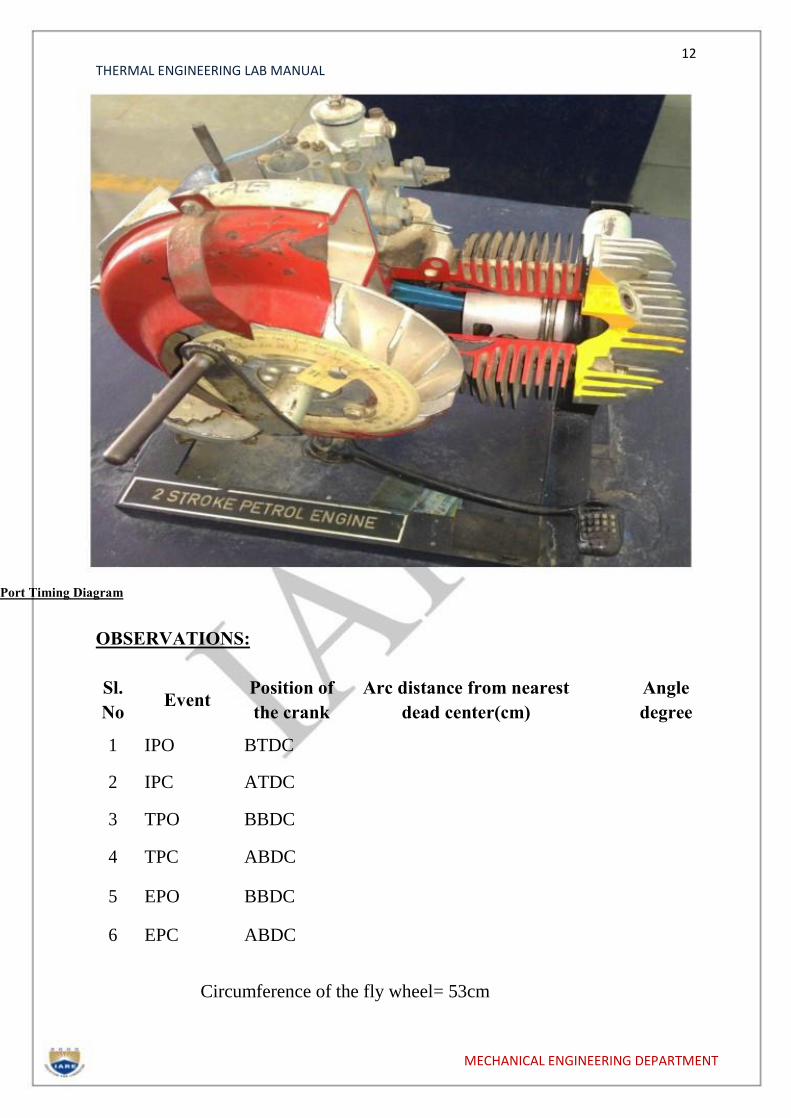
Port Timing Diagram
OBSERVATIONS:
Sl.
No Event
Position of
the crank
Arc distance from nearest
dead center(cm)
Angle
degree
1 IPO BTDC
2 IPC ATDC
3 TPO BBDC
4 TPC ABDC
5 EPO BBDC
6 EPC ABDC
Circumference of the fly wheel= 53cm
MECHANICAL ENGINEERING DEPARTMENT
13 THERMAL ENGINEERING LAB MANUAL
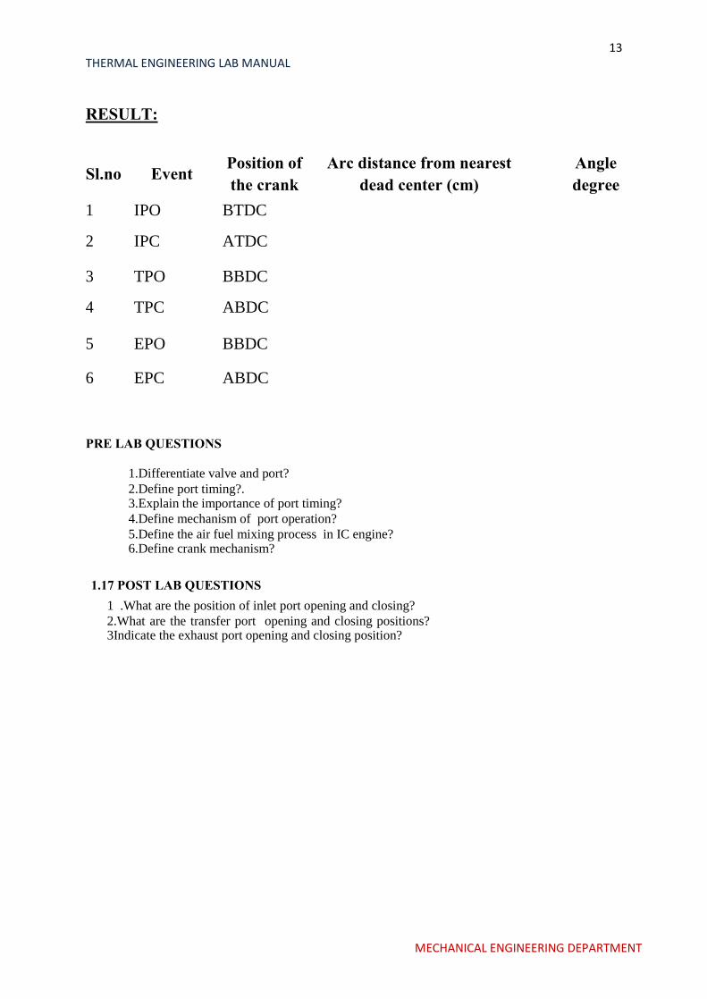
RESULT:
Sl.no Event Position of
the crank
Arc distance from nearest
dead center (cm)
Angle
degree
1 IPO BTDC
2 IPC ATDC
3 TPO BBDC
4 TPC ABDC
5 EPO BBDC
6 EPC ABDC
PRE LAB QUESTIONS
1.Differentiate valve and port? 2.Define port timing?. 3.Explain the importance of port timing? 4.Define mechanism of port operation? 5.Define the air fuel mixing process in IC engine? 6.Define crank mechanism?
1.17 POST LAB QUESTIONS
1 .What are the position of inlet port opening and closing? 2.What are the transfer port opening and closing positions? 3Indicate the exhaust port opening and closing position?
MECHANICAL ENGINEERING DEPARTMENT

14 THERMAL ENGINEERING LAB MANUAL
EXPERIMENT NO: 3
PERFORMANCE TEST FOR
4 STROKE S I ENGINE
MECHANICAL ENGINEERING DEPARTMENT
15 THERMAL ENGINEERING LAB MANUAL
INTRODUCTION:
The Test Rig is multicylinder petrol engine coupled to a hydraulic brake
and complete with all measurement systems, auto electrical panel ,
self-starter assembly, Morse test setup,battery etc., Engine is with 4 cylinder
water cooled radiator is provided. Engine cooling is done by through
continuous flowing water.
SPECIFICATIONS:
1 Engine coupled to hydraulic brake
2.Clutch arrangement
3.Morse test setup
4.Stand,Panel with all measurements
5.Air tank, fuel tank
6.Auto electrical with battery
DESCRIPTION OF THE APPARATUS:
Engine: Either PREMIERE / AMBASSODAR four cylinder four stroke
water cooled automotive (reclaim) spark ignited with all accessories. Make:
PREMIERE
Speed: max 5000rpm
Power: 23 HP at max speed No of cylinders: FOUR Firing order: 1-3-4-2 Cylinder bore:
73mm Stroke length: 70mm Spark plug gap: 0.64mm
Other components include battery, starter motor, alternator/DC
dynamo,ignition switch, solenoid, cables, accelerator assembly, radiator,
valves etc.
HYDRAULIC BRAKE:
It is a reaction type hydraulic dynamometer; a stator body can swing in its axis,
depending upon the torque on the shaft. The shaft is extended at both ends and
supported between two bearings. Rotor is coupled at one end to the engine
shaft. Water is allowed inside through stator and flows inside pockets of rotor
and comes out of rotor. Any closure of valve or any restriction of
MECHANICAL ENGINEERING DEPARTMENT

16 THERMAL ENGINEERING LAB MANUAL
flowing water, created breaking effect on the shaft, and which is reflected
inopposition force of stator. Stator while reacting to proportional force pulls a
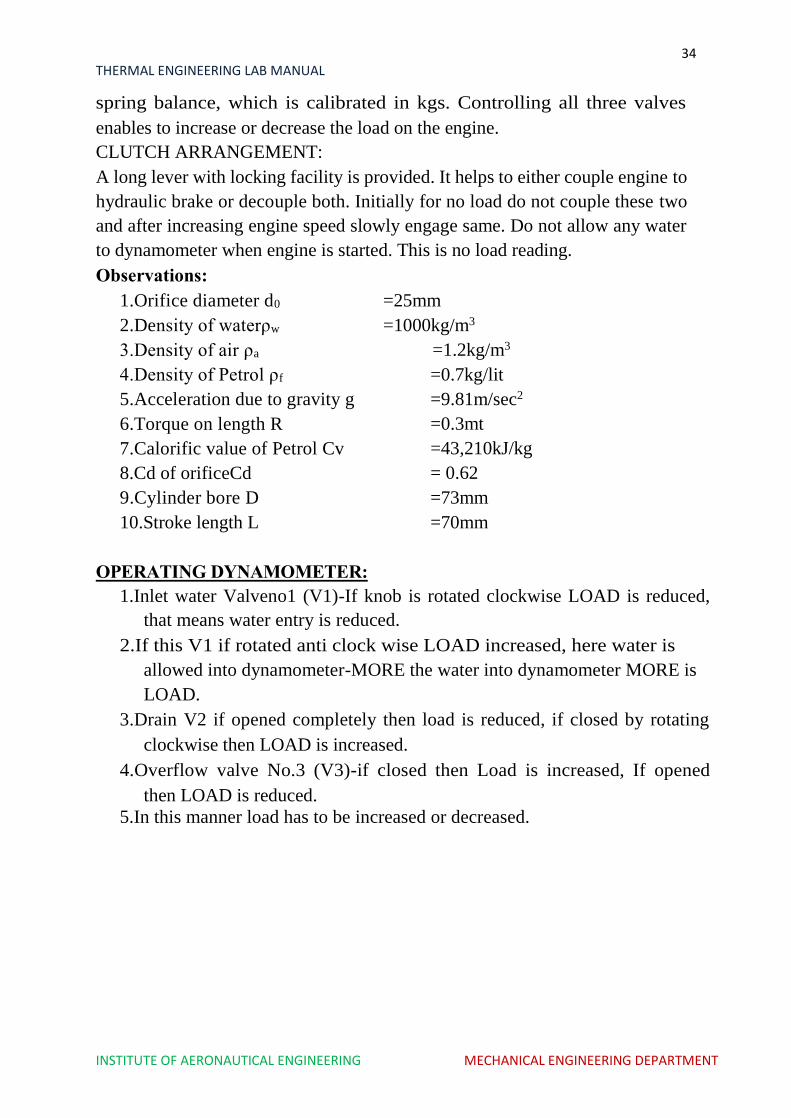
spring balance, which is calibrated in kgs. Controlling all three valves
enables to increase or decrease the load on the engine.
CLUTCH ARRANGEMENT:
A long lever with locking facility is provided. It helps to either couple engine to
hydraulic brake or decouple both. Initially for no load do not couple these two
and after increasing engine speed slowly engage same. Do not allow any water
to dynamometer when engine is started. This is no load reading.
OBSERVATIONS:
1.Orifice diameter d0 =25mm
2.Density of water ρw =1000kg/m3
3.Density of air ρa =1.2kg/m3
4.Density of Petrol ρf =0.7kg/lit
5.Acceleration due to gravity g =9.81m/sec2
6.Torque on length R =0.3mt
7.Calorific value of Petrol Cv =43,210kJ/kg
8.Cd of orifice = 0.62
9.Cylinder bore D =73mm
10. Stroke length L =70mm
AIM:
The experiment is conducted to
a. To study and understand the performance characteristics of the engine.
b. To draw Performance curves and compare with standards.
PROCEDURE:
1. Check the lubricating oil level.
2. Check the fuel level.
3. Check and Release the load on the dynamometer if loaded.
4. Check the necessary electrical connections and switch on thePanel.
5. Provide the Battery Connections.
6. Open water valve for engine cooling and adjust flow rate , say 4to 6 LPM
CONSTANT SPEED TEST:
1.After engine picks up speed slowly, engage clutch, now engine is coupled
with hydraulic dynamometer.
MECHANICAL ENGINEERING DEPARTMENT
17 THERMAL ENGINEERING LAB MANUAL
2.With the help of accelerator, increase engine to say 1500rpm.
3.Note down the time required for 10litres of water flow, time required for
10cc of fuel, manometer reading, spring balance reading, all
temperatures.
4.For next load allow more water into dynamometer and also adjust throttle
valve such that engine is loaded but with same RPM, 1500rpm.
5.Note down all readings.
6.Repeat experiment for next higher load, max 8kw.
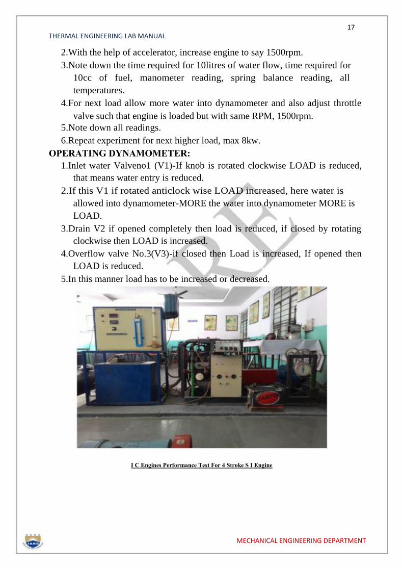
OPERATING DYNAMOMETER:
1.Inlet water Valveno1 (V1)-If knob is rotated clockwise LOAD is reduced,
that means water entry is reduced.
2.If this V1 if rotated anticlock wise LOAD increased, here water is
allowed into dynamometer-MORE the water into dynamometer MORE is
LOAD.
3.Drain V2 if opened completely then load is reduced, if closed by rotating
clockwise then LOAD is increased.
4.Overflow valve No.3(V3)-if closed then Load is increased, If opened then
LOAD is reduced.
5.In this manner load has to be increased or decreased. I C Engines Performance Test For 4 Stroke S I Engine
MECHANICAL ENGINEERING DEPARTMENT

18 THERMAL ENGINEERING LAB MANUAL
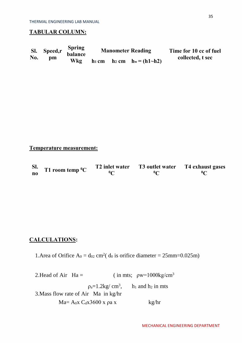
TABULAR COLUMN:
Sl.
No.
Speed,
rpm
Spring
balance
Wkg
Manometer Reading
Time for 10 cc of fuel
collected,t sec
h1cm h2 cm Hw=(h1~h2)
CALCULATIONS:
1.Area of Orifice A0 =( π/4) d02 sq.cm (d0 is orifice diameter =
25mm=0.025m)
2.Head of Air Ha = in mts; ρw=1000kg/cm3
ρa=1.2kg/ cm3, h1 and h2 in mts
3.Mass flow rate of Air Ma in kg/hr
Ma= A0x Cdx3600 x ρa x kg/hr
4.Total fuel consumption TFC : in kg/hr
TFC =
5.Brake Power BP in Kw
a.With hydraulic brake dynamometer ( reaction type)
b.BP= [ 2 x π x 9.81 x N x W x R]/60,000 kW
i. Where R= Load arm length = 0.3mts
ii. W= load shown on spring balance,kg
iii. N= speed in rpm
6.Specific fuel consumption: SFC in Kg/Kw-hr
1.SFC = TFC/BP
7.Air Fuel ratio : A/F
A/F = Ma/TFC
MECHANICAL ENGINEERING DEPARTMENT

19 THERMAL ENGINEERING LAB MANUAL
8.Brake Thermal efficiency
9.ηbth = [BP/TFC x CV ]x 100%,
10.Indicated Thermal efficiency
11.ηith = [IP/TFC x CV ]x 100%,
GRAPHS:
Plot curves of BP vs. TFC, SFC, and A/F.
PRE LAB QUESTIONS:
1.What are the 4strokes of SI engines?
2.What is the working cycle of SI Engine?
3.List out the performance parameters?
4.Indicate the different types of loads?
5.Differentiate SFC and TFC?
6.Concept of mass flow rate of air?
POST LAB QUESTIONS:
1.Dfifferentiate brake power and indicated power?
2.Define brake thermal efficiency?
3.Indicate mechanical efficiency in terms of BP and IP?
MECHANICAL ENGINEERING DEPARTMENT
20 THERMAL ENGINEERING LAB MANUAL
EXPERIMENT NO:4
IC ENGINES PERFORMANCE TEST
FOR
2 STROKE S I ENGINE
MECHANICAL ENGINEERING DEPARTMENT
21 THERMAL ENGINEERING LAB MANUAL
OBJECTIVE: To conduct LOAD TEST
To calculate brake thermal efficiency
To determine A/F ratio.
INTRODUCTION:
Test rig is with two stroke Bajaj make Petrol engine, coupled to Electrical
dynamometer. Engine is air cooled type, hence only load test can be conducted at
a constant speed of 3000rpm. Test rig is complete with base, air
measurement, fuel measurement and temperature measurement system.
Thermocouple is employed tomeasure temperature digitally.
Two stroke engines are coupled with ports closing at inlet and exhaust.
Hence when compared to four stroke engine, it has low fuel efficiency because
scavenging effect. But its construction and maintenance is easy, and costs less.
TEST SET UP:
01. Main chassis, engine coupled to dynamometer
02. Control desk with all measurements
03. Hoses, cables, thermocouples, misc.
CHASIS:
It is made from strong MS channels, with foundation facility. Supportbracket, to
hold by hand while kick starting the engine.
Engine:
Bajaj classic/Chetek
Two stroke, single cylinder, air cooled, petrol driven
Compression Ratio : 7.4:1
Ignition timing :Spark advance of 22 degree before TDC
Bore :57 mm
Stroke length :57 mm
Displacement :145.45 cc
Observations:
1.Orifice diameter d0 =15.25mm
2.Density of water ρw =1000kg/m3
3.Density of air ρa =1.2kg/m3
4.Density of Petrol ρf =0.7kg/lit
5.Acceleration due to gravity g =9.81m/sec2
6.Alternator efficiency ηg =70%
7.Calorific value of Petrol Cv =43,210kJ/kg
MECHANICAL ENGINEERING DEPARTMENT
22 THERMAL ENGINEERING LAB MANUAL
8.Cd of orifice = 0.62
9.Cylinder bore D =57mm
10.Stroke length L =57mm
PROCEDURE:
1.Fill up water in manometer to required level
2.Ensure petrol level in the fuel tank.
3.Ensure engine oil.
4.Put MCB of alternator to ON, switch of all load banks or bring aluminum
conductor of water loading rheostat above water level.
5.Add water
6.Switch ON ignition
7.Fix accelerator at some setting
8.Now kick start the engine and when it pickups speed adjust at 3000 rpm
9.at this no load note down manometer, speed ,temperature, voltage current
and time for 10 cc of fuel consumption.
10.Repeat for different loads.
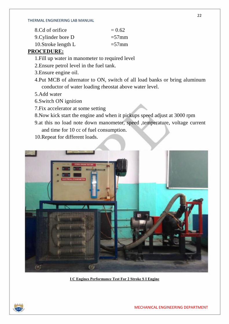
I C Engines Performance Test For 2 Stroke S I Engine
MECHANICAL ENGINEERING DEPARTMENT
23 THERMAL ENGINEERING LAB MANUAL
TABULAR COLUMN:
Sl.
No.
Speed,
rpm
Spring
balance
Wkg
Manometer Reading Time for 10 cc
offuel collected, t
sec h1 cm h2 cm hw= (h1~h2)
CALCULATIONS:
1. Area of Orifice A0 =( π/4) d02 sq.cm ( d0 is orifice diameter = mm)
2. Manometer Head Ha = ( in mts; ρw=1000kg/cm3
ρa=1.2kg/ cm3, h1 and h2 in mts
3. Mass flow rate of Air Ma in kg/hr
Ma= A0x Cdx3600 x ρa x kg/hr
4. Total fuel consumption TFC : in kg/hr
TFC =
5. Brake Power BP in Kw
BP= x1000 kW
6. Specific fuel consumption: SFC in Kg/Kw-hr
SFC = TFC/BP
7. Air Fuel ratio : A/F
A/F = Ma/TFC
8. Brake Thermal efficiency
ηbth = [BP/TFC x CV] x 100%,
GRAPHS:
Plot curves of BP vs. TFC, SFC, A/F,
PRECAUTIONS:
1.Do not allow speed above 3000 rpm
MECHANICAL ENGINEERING DEPARTMENT
24 THERMAL ENGINEERING LAB MANUAL
2.Don’t increase load above 8 Amps
3.Don’t run engine without engine oil
4.Mix petrol and 2T oil at 1 liter.
PRE LAB QUESTIONS:
1.What are the 2strokes of SI engines?
2.What is the working cycle of SI Engine?
3.List out the performance parameters?
4.Indicate the different types of loads?
5.Differentiate SFC and TFC?
6.Concept of mass flow rate of air?
POST LAB QUESTIONS:
1.Dfifferentiate brake power and indicated power?
2.Define brake thermal efficiency?
3.Indicate mechanical efficiency in terms of BP and IP?
MECHANICAL ENGINEERING DEPARTMENT
25 THERMAL ENGINEERING LAB MANUAL
EXPIREMENT: 5
IC ENGINE MORSE REATRDATION
MOTORING TESTS
MECHANICAL ENGINEERING DEPARTMENT

26 THERMAL ENGINEERING LAB MANUAL
INTRODUCTION:
The Test Rig is multi cylinder petrol engine coupled to a hydraulic brake
and complete with all measurement systems, auto electrical panel ,
self-starter assembly, Morse test setup, battery etc., Engine is with 4 cylinder
water cooled radiator is provided. Engine cooling is done by through
continuous flowing water.
SPECIFICATIONS:
1.Engine coupled to hydraulic brake
2.Clutch arrangement
3.Morse test setup
4.Stand, Panel with all measurements
5.Air tank, fuel tank
6.Auto electrical with battery
DESCRIPTION OF THE APPARATUS:
Engine : Either PREMIERE / AMBASSODAR four cylinder
four stroke water cooled automotive (reclaim) spark
ignited with all accessories.
Make : PREMIERE
Speed : max 5000rpm
Power : 23 HP at max speed
No of cylinders : FOUR
Firing order : 1-3-4-2
Cylinder bore : 73mm
Stroke length : 70mm
Spark plug gap : 0.64mm
Other components include battery, starter motor, alternator/DC dynamo,
ignition switch, solenoid, cables, accelerator assembly, radiator, valves etc.
HYDRAULIC BRAKE:
It is a reaction type hydraulic dynamometer; a stator body can swing in its axis,
depending upon the torque on the shaft. The shaft is extended at both ends and
supported between two bearings. Rotor is coupled at one end to the engine
shaft. Water is allowed inside through stator and flows inside pockets
MECHANICAL ENGINEERING DEPARTMENT

27 THERMAL ENGINEERING LAB MANUAL
of rotor and comes out of rotor. Any closure of valve or any restriction of
flowing water, created breaking effect on the shaft, and which is reflected in
opposition force of stator. Stator while reacting to proportional force pulls a
spring balance, which is calibrated in kgs. Controlling all three valves
enables to increase or decrease the load on the engine.
CLUTCH ARRANGEMENT:
A long lever with locking facility is provided. It helps to either couple engine to
hydraulic brake or decouple both. Initially for no load do not couple these two
and after increasing engine speed slowly engage same. Do not allow any water
to dynamometer when engine is started. This is no load reading.
OBSERVATIONS:
1.Orifice diameter d0 =25mm
2.Density of water ρw =1000kg/m3
3.Density of air ρa =1.2kg/m3
4.Density of Petrol ρf =0.7kg/lit
5.Acceleration due to gravity g =9.81m/sec2
6.Torque on length R =0.3mt
7.Calorific value of Petrol Cv =43,210kJ/kg
8.Cd of orifice = 0.62
9.Cylinder bore D =73mm
10.Stroke length L =70mm
AIM:
To Conduct Morse test to determine frictional power
To conduct motoring test
CONSTANT SPEED TEST:
1.After engine picks up speed slowly, engage clutch, now engine is coupled
with hydraulic dynamometer.
2.With the help of accelerator, increase engine to say 1500rpm.
3.Note down the time required for 10litres of water flow, time required for
10cc of fuel, manometer reading, spring balance reading, all
temperatures.
4.For next load allow more water into dynamometer and also adjust throttle
valve such that engine is loaded but with same RPM, 1500rpm.
5.Note down all readings.
6.Repeat experiment for next higher load, max 8kw.
MECHANICAL ENGINEERING DEPARTMENT
28 THERMAL ENGINEERING LAB MANUAL
OPERATING DYNAMOMETER:
1.Inlet water Valveno1 (V1)-If knob is rotated clockwise LOAD is reduced,
that means water entry is reduced.
2.If this V1 if rotated anti clock wise LOAD increased, here water is
allowed into dynamometer-MORE the water into dynamometer MORE is
LOAD.
3.Drain V2 if opened completely then load is reduced, if closed by rotating
clockwise then LOAD is increased.
4.Overflow valve No.3 (V3)-if closed then Load is increased, If opened
then LOAD is reduced.
5.In this manner load has to be increased or decreased.
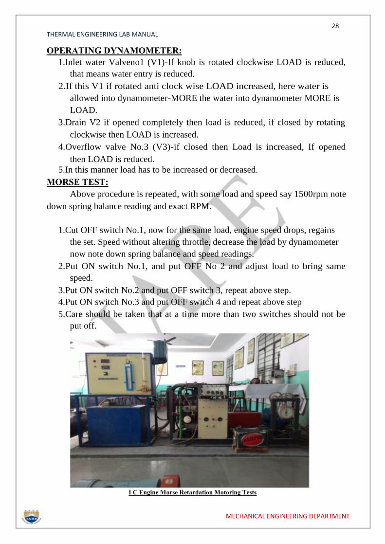
MORSE TEST:
Above procedure is repeated, with some load and speed say 1500rpm note
down spring balance reading and exact RPM.
1.Cut OFF switch No.1, now for the same load, engine speed drops, regains
the set. Speed without altering throttle, decrease the load by dynamometer
now note down spring balance and speed readings.
2.Put ON switch No.1, and put OFF No 2 and adjust load to bring same
speed.
3.Put ON switch No.2 and put OFF switch 3, repeat above step.
4.Put ON switch No.3 and put OFF switch 4 and repeat above step
5.Care should be taken that at a time more than two switches should not be
put off. I C Engine Morse Retardation Motoring Tests
MECHANICAL ENGINEERING DEPARTMENT
29 THERMAL ENGINEERING LAB MANUAL
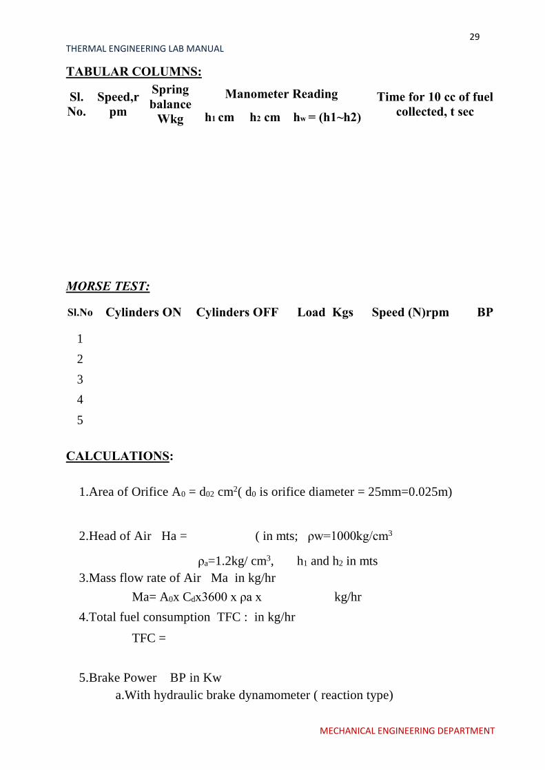
TABULAR COLUMNS:
Sl.
No.
Speed,r
pm
Spring
balance
Wkg
Manometer Reading Time for 10 cc of fuel
collected, t sec h1 cm h2 cm hw = (h1~h2)
MORSE TEST:
Sl.No Cylinders ON Cylinders OFF Load Kgs Speed (N)rpm BP
1
2
3
4
5
CALCULATIONS:
1.Area of Orifice A0 = d02 cm2( d0 is orifice diameter = 25mm=0.025m)
2.Head of Air Ha =
( in mts; ρw=1000kg/cm3
ρa=1.2kg/ cm3, h1 and h2 in mts
3.Mass flow rate of Air Ma in kg/hr
Ma= A0x Cdx3600 x ρa x kg/hr
4.Total fuel consumption TFC : in kg/hr
TFC =
5.Brake Power BP in Kw
a.With hydraulic brake dynamometer ( reaction type)
MECHANICAL ENGINEERING DEPARTMENT

30 THERMAL ENGINEERING LAB MANUAL
b.BP= [ 2 x π x 9.81 x N x W x R]/60,000 kW
Where
R= Load arm length = 0.3mts
W= load shown on spring balance,kg
N= speed in rpm
6.Specific fuel consumption: SFC in Kg/Kw-hr
1.SFC = TFC/BP
7.Air Fuel ratio : A/F
A/F = Ma/TFC
8.Brake Thermal efficiency
ηbth = [BP/TFC x CV] x 100%,
With MORSE TEST:
a.Determine B, B1,B2,B3 and B4 - Brake powers as above
b.Indicated Power in kW , IP = [ 4xB]-[B1+B2+B3+B4] kW
c.Mechanical Efficiency ηm = BP/IP
9. 9.Indicated Thermal efficiency
ηith= [IP/TFC x CV] x 100%.
GRAPHS:
Plot curves of BP vs. TFC, SFC, A/F, and Mechanical efficiency.
MOTORING TEST:
CALCULATIONS:
1.FRICTION POWER, FP
FP = (V*I) / 1000 KW
Where,
V= voltmeter reading on motoring side I
= ammeter reading on motoring side
MECHANICAL ENGINEERING DEPARTMENT

31 THERMAL ENGINEERING LAB MANUAL
PRE LAB QUESTIONS:
1.What are the 4strokes of SI engines?
2.What is the working cycle of SI Engine?
3.List out the performance parameters?
4.Indicate the different types of loads?
5.Differentiate SFC and TFC?
6.What are the different methods to find frictional power?
POST LAB QUESTIONS:
1.Dfifferentiate brake power and indicated power?
2.Define brake thermal efficiency?
3.Indicate mechanical efficiency in terms of BP and IP?
4.Explain the procedure for finding frictional power using Morse test?
MECHANICAL ENGINEERING DEPARTMENT
32 THERMAL ENGINEERING LAB MANUAL
EXPERIMENT NO: 6
I C ENGINE HEAT BALANCE -S I
ENGINE
MECHANICAL ENGINEERING DEPARTMENT
33 THERMAL ENGINEERING LAB MANUAL
AIM: To conduct Heat Balance on S I Engine.
INTRODUCTION:
The Test Rig is multi cylinder petrol engine coupled to a hydraulic brake
and complete with all measurement systems, auto electrical panel ,
self-starter assembly, Morse test setup, battery etc., Engine is with 4 cylinder
water cooled radiator is provided. Engine cooling is done by through
continuous flowing water.
Specifications:
1.Engine coupled to hydraulic brake
2.Clutch arrangement
3.Morse test setup
4.Stand, Panel with all measurements
5.Air tank, fuel tank
6.Auto electrical with battery
DESCRIPTION OF THE APPARATUS:
Engine: Either PREMIERE / AMBASSODAR four cylinder four stroke
water cooled automotive (reclaim) spark ignited with all accessories.
Make : PREMIERE
Speed : max 5000rpm
Power : 23 HP at max speed
No of cylinders : FOUR
Firing order : 1-3-4-2
Cylinder bore : 73mm
Stroke length : 70mm
Spark plug gap : 0.64mm
Other components include battery, starter motor, alternator/DC
dynamo, ignition switch, solenoid, cables, accelerator assembly, radiator,
valves etc.
HYDRAULIC BRAKE:
It is a reaction type hydraulic dynamometer; a stator body can swing in its axis,
depending upon the torque on the shaft. The shaft is extended at both ends and
supported between two bearings. Rotor is coupled at one end to the engine
shaft. Water is allowed inside through stator and flows inside pockets of rotor
and comes out of rotor. Any closure of valve or any restriction of flowing
water, created breaking effect on the shaft, and which is reflected in opposition
force of stator. Stator while reacting to proportional force pulls a
MECHANICAL ENGINEERING DEPARTMENT
34 THERMAL ENGINEERING LAB MANUAL
spring balance, which is calibrated in kgs. Controlling all three valves
enables to increase or decrease the load on the engine.
CLUTCH ARRANGEMENT:
A long lever with locking facility is provided. It helps to either couple engine to
hydraulic brake or decouple both. Initially for no load do not couple these two
and after increasing engine speed slowly engage same. Do not allow any water
to dynamometer when engine is started. This is no load reading.
Observations:
1.Orifice diameter d0
2.Density of waterρw
3.Density of air ρa
4.Density of Petrol ρf
5.Acceleration due to gravity g
6.Torque on length R
7.Calorific value of Petrol Cv
8.Cd of orificeCd
9.Cylinder bore D
10.Stroke length L
OPERATING DYNAMOMETER:
=25mm
=1000kg/m3
=1.2kg/m3
=0.7kg/lit
=9.81m/sec2
=0.3mt
=43,210kJ/kg
= 0.62
=73mm
=70mm
1.Inlet water Valveno1 (V1)-If knob is rotated clockwise LOAD is reduced,
that means water entry is reduced.
2.If this V1 if rotated anti clock wise LOAD increased, here water is
allowed into dynamometer-MORE the water into dynamometer MORE is
LOAD.
3.Drain V2 if opened completely then load is reduced, if closed by rotating
clockwise then LOAD is increased.
4.Overflow valve No.3 (V3)-if closed then Load is increased, If opened
then LOAD is reduced.
5.In this manner load has to be increased or decreased.
INSTITUTE OF AERONAUTICAL ENGINEERING MECHANICAL ENGINEERING DEPARTMENT
35 THERMAL ENGINEERING LAB MANUAL
TABULAR COLUMN:
Sl.
No.
Speed,r
pm
Spring
balance
Wkg
Manometer Reading Time for 10 cc of fuel
collected, t sec h1 cm h2 cm hw = (h1~h2)
Temperature measurement:
Sl.
no T1 room temp 0C
T2 inlet water 0C
T3 outlet water 0C
T4 exhaust gases 0C
CALCULATIONS:
1.Area of Orifice A0 = d02 cm2( d0 is orifice diameter = 25mm=0.025m)
2.Head of Air Ha =
( in mts; ρw=1000kg/cm3
ρa=1.2kg/ cm3, h1 and h2 in mts
3.Mass flow rate of Air Ma in kg/hr
Ma= A0x Cdx3600 x ρa x kg/hr
MECHANICAL ENGINEERING DEPARTMENT
36 THERMAL ENGINEERING LAB MANUAL
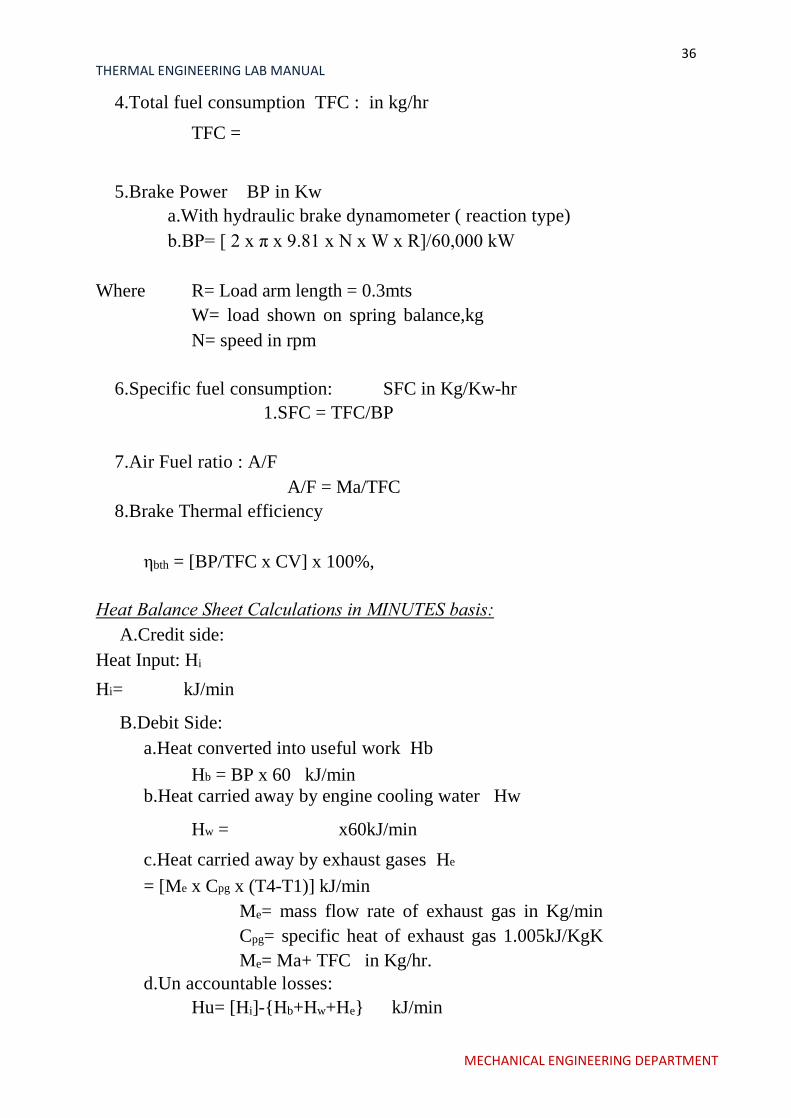
4.Total fuel consumption TFC : in kg/hr
TFC =
5.Brake Power BP in Kw
a.With hydraulic brake dynamometer ( reaction type)
b.BP= [ 2 x π x 9.81 x N x W x R]/60,000 kW
Where
R= Load arm length = 0.3mts
W= load shown on spring balance,kg
N= speed in rpm
6.Specific fuel consumption: SFC in Kg/Kw-hr
1.SFC = TFC/BP
7.Air Fuel ratio : A/F
A/F = Ma/TFC
8.Brake Thermal efficiency
ηbth = [BP/TFC x CV] x 100%,
Heat Balance Sheet Calculations in MINUTES basis:
A.Credit side:
Heat Input: Hi
Hi= kJ/min
B.Debit Side:
a.Heat converted into useful work Hb
Hb = BP x 60 kJ/min
b.Heat carried away by engine cooling water Hw
Hw = x60kJ/min
c.Heat carried away by exhaust gases He
= [Me x Cpg x (T4-T1)] kJ/min
Me= mass flow rate of exhaust gas in Kg/min
Cpg= specific heat of exhaust gas 1.005kJ/KgK
Me= Ma+ TFC in Kg/hr.
d.Un accountable losses:
Hu= [Hi]-{Hb+Hw+He} kJ/min
MECHANICAL ENGINEERING DEPARTMENT
37 THERMAL ENGINEERING LAB MANUAL
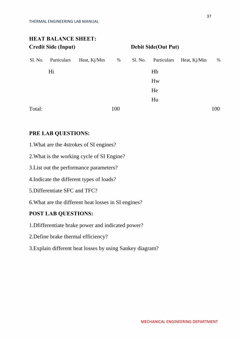
HEAT BALANCE SHEET: Credit Side (Input) Debit Side(Out Put)
Sl. No. Particulars Heat, Kj/Min % Sl. No. Particulars Heat, Kj/Min %
Hi Hb
Hw
He
Hu
Total: 100 100
PRE LAB QUESTIONS:
1.What are the 4strokes of SI engines?
2.What is the working cycle of SI Engine?
3.List out the performance parameters?
4.Indicate the different types of loads?
5.Differentiate SFC and TFC?
6.What are the different heat losses in SI engines?
POST LAB QUESTIONS:
1.Dfifferentiate brake power and indicated power?
2.Define brake thermal efficiency?
3.Explain different heat losses by using Sankey diagram?
MECHANICAL ENGINEERING DEPARTMENT
38 THERMAL ENGINEERING LAB MANUAL
EXPERIMENT NO: 07
I C ENGINE ECONOMICAL SPEED TESTONS
I ENGINE
MECHANICAL ENGINEERING DEPARTMENT
39 THERMAL ENGINEERING LAB MANUAL
INTRODUCTION:
The Test Rig is multi cylinder petrol engine coupled to a hydraulic brake
and complete with all measurement systems, auto electrical panel , self-starter
assembly, Morse test setup, battery etc., Engine is with 4 cylinder water cooled
radiator is provided. Engine cooling is done by through continuous flowing
water.
SPECIFICATIONS:
Engine coupled to hydraulic brake
Clutch arrangement
Morse test setup
Stand, Panel with all measurements
Air tank, fuel tank
Auto electrical with battery
DESCRIPTION OF THE APPARATUS:
Engine : Either PREMIERE / AMBASSODAR four cylinder four stroke
water cooled automotive (reclaim) spark ignited with all accessories.
Make : PREMIERE
Speed : max 5000rpm
Power : 23 HP at max speed
No of cylinders : FOUR
Firing order : 1-3-4-2
Cylinder bore : 73mm
Stroke length : 70mm
Spark plug gap : 0.64mm
Other components include battery, starter motor, alternator/DC dynamo,
ignition switch, solenoid, cables, accelerator assembly, radiator, valves etc.
HYDRAULIC BRAKE:
It is a reaction type hydraulic dynamometer; a stator body can swing in its axis,
depending upon the torque on the shaft. The shaft is extended at both ends and
supported between two bearings. Rotor is coupled at one end to the engine
shaft. Water is allowed inside through stator and flows inside pockets of rotor and
comes out of rotor. Any closure of valve or any restriction of flowing water, created
breaking effect on the shaft, and which is reflected in opposition force of stator.
Stator while reacting to proportional force pulls a spring balance,
MECHANICAL ENGINEERING DEPARTMENT

40 THERMAL ENGINEERING LAB MANUAL
which is calibrated in kgs. Controlling all three valves enables to increase or
decrease the load on the engine.
CLUTCH ARRANGEMENT:
A long lever with locking facility is provided. It helps to either couple engine to
hydraulic brake or decouple both. Initially for no load do not couple these two and
after increasing engine speed slowly engage same. Do not allow any water to
dynamometer when engine isreading.
OBSERVATIONS:
11.Orifice diameter d0 =25mm
12.Density of water ρw =1000kg/m3
13.Density of air ρa =1.2kg/m3
14.Density of Petrol ρf =0.7kg/lit
15.Acceleration due to gravity g =9.81m/sec2
16.Torque on length R =0.3mt
17.Calorific value of Petrol Cv =43,210kJ/kg
18.Cd of orifice = 0.62
19.Cylinder bore D =73mm
20.Stroke length L =70mm
AIM:
To Conduct Economical speed test on SI engine
CONSTANT SPEED TEST:
1.After engine picks up speed slowly, engage clutch, now engine is coupled
with hydraulic dynamometer.
2.With the help of accelerator, increase engine to say 1500rpm.
3.Note down the time required for 10litres of water flow, time required for
10cc of fuel, manometer reading, spring balance reading, all
temperatures.
4.For next load allow more water into dynamometer and also adjust throttle
valve such that engine is loaded but with same RPM, 1500rpm.
5.Note down all readings.
6.Repeat experiment for next higher load, max 8kw.
OPERATING DYNAMOMETER:
6.Inlet water Valveno1 (V1)-If knob is rotated clockwise LOAD is reduced,
that means water entry is reduced.
MECHANICAL ENGINEERING DEPARTMENT

41 THERMAL ENGINEERING LAB MANUAL
7.If this V1 if rotated anti clock wise LOAD increased, here water is
allowed into dynamometer-MORE the water into dynamometer MORE is
LOAD.
8.Drain V2 if opened completely then load is reduced, if closed by rotating
clockwise then LOAD is increased.
9.Overflow valve No.3 (V3)-if closed then Load is increased, If opened
then LOAD is reduced.
10.In this manner load has to be increased or decreased.
TABULAR COLUMN:
Sl.
No.
Speed,r
pm
Spring
balance
Wkg
Manometer Reading Time for 10 cc of fuel
collected, t sec h1 cm h2 cm hw = (h1~h2)
MECHANICAL ENGINEERING DEPARTMENT
42 THERMAL ENGINEERING LAB MANUAL
CALCULATIONS:
1.Area of Orifice A0 = d02 cm2( d0 is orifice diameter = 25mm=0.025m)
2.Head of Air Ha =
( in mts; ρw=1000kg/cm3
ρa=1.2kg/ cm3, h1 and h2 in mts
3.Mass flow rate of Air Ma in kg/hr
Ma= A0x Cdx3600 x ρa x kg/hr
4.Total fuel consumption TFC : in kg/hr
TFC =
5.Brake Power BP in Kw
a.With hydraulic brake dynamometer ( reaction type)
b.BP= [ 2 x π x 9.81 x N x W x R]/60,000 kW
Where R= Load arm length = 0.3mts
W= load shown on spring balance,kg N= speed in rpm
6.Specific fuel consumption: SFC in Kg/Kw-hr
1.SFC = TFC/BP
7.Air Fuel ratio : A/F
A/F = Ma/TFC
8.Brake Thermal efficiency
ηbth = [BP/TFC x CV] x 100%,
Graphs:
Draw graph BP vs ηbth,load,A/F.
MECHANICAL ENGINEERING DEPARTMENT

43 THERMAL ENGINEERING LAB MANUAL
PRE LAB QUESTIONS:
1.What are the 4strokes of SI engines?
2.What is the working cycle of SI Engine?
3.List out the performance parameters?
4.Indicate the different types of loads?
5.Differentiate SFC and TFC?
6.Concept of mass flow rate of air?
POST LAB QUESTIONS:
1.Dfifferentiate brake power and indicated power?
2.Define brake thermal efficiency?
3.Indicate mechanical efficiency in terms of BP and IP?
MECHANICAL ENGINEERING DEPARTMENT

44 THERMAL ENGINEERING LAB MANUAL
EXPERIMENT 8
HEAT BALANCE TEST ON DIESEL
ENGINE
MECHANICAL ENGINEERING DEPARTMENT
45 THERMAL ENGINEERING LAB MANUAL
INTRODUCTION
A machine, which uses heat energy obtained from combustion of fuel and
converts it into mechanical energy, is known as a Heat Engine. They are
classified as External and Internal Combustion Engine. In an External
Combustion Engine, combustion takes place outside the cylinder and the heat
generated from the combustion of the fuel is transferred to the working fluid
which is then expanded to develop the power. An Internal Combustion Engine is
one where combustion of the fuel takes place inside the cylinder and converts heat
energy into mechanical energy. IC engines may be classified based on the
working cycle, thermodynamic cycle, speed, fuel, cooling, method of ignition,
mounting of engine cylinder and application.
Diesel Engine is an internal combustion engine, which uses heavy oil or
diesel oil as a fuel and operates on two or four stroke. In a 4-stroke Diesel
engine, the working cycle takes place in two revolutions of the crankshaft or 4
strokes of the piston. In this engine, pure air is sucked to the engine and the fuel is
injected with the combustion taking place at the end of the compression stroke.
The power developed and the performance of the engine depends on the condition
of operation. So it is necessary to test an engine for different conditions
based on the requirement.
DESCRIPTION OF THE APPARATUS:
a.Electrical Loading (Water cooled)
1.
The equipment consists of KIRLOSKAR Diesel Engine (Crank
started) of 5hp (3.7kW) capacity and is Water cooled.
2. The Engine is coupled to a same capacity DC alternator with
resistance heaters to dissipate the energy.
3. Thermocouples are provided at appropriate positions and are read
by a digital temperature indicator with channel selector to select the
position.
4. Rota meters of range 15LPM & 10LPM are used for direct
measurement of water flow rate to the engine and calorimeter
respectively.
5. Engine Speed and the load applied at various conditions is
determined by a Digital RPM Indicator and spring balance reading.
MECHANICAL ENGINEERING DEPARTMENT

46 THERMAL ENGINEERING LAB MANUAL
6. A separate air box with orifice assembly is provided for
regularizing and measuring the flow rate of air. The pressure
difference at the orifice is measured by means of Manometer.
7. A volumetric flask with a fuel distributor is provided for
measurement and directing the fuel to the engine respectively.
EXPERIMENTATION:
AIM: The experiment is conducted to
a)To study and understand the performance characteristics of the
engine.
b)To draw Performance curves and compare with standards.
PROCEDURE:
1.Give the necessary electrical connections to the panel.
2.Check the lubricating oil level in the engine.
3.Check the fuel level in the tank.
4.Allow the water to flow to the engine and the calorimeter and adjust the
flow rate to 6lpm & 3lpm respectively.
5.Release the load if any on the dynamometer.
6.Open the three-way cock so that fuel flows to the engine.
7.Start the engine by cranking.
8.Allow to attain the steady state.
9.Load the engine by slowly tightening the yoke rod handle of the Rope
brake drum.
10.Note the following readings for particular condition,
a.Engine Speed
b.Time taken for ____cc of diesel consumption
c.Rota meter reading.
d.Manometer readings, in cm of water &
e.Temperatures at different locations.
11.Repeat the experiment for different loads and note down the above
readings.
12.After the completion release the load and then switch of the engine.
13.Allow the water to flow for few minutes and then turn it off.
MECHANICAL ENGINEERING DEPARTMENT
47 THERMAL ENGINEERING LAB MANUAL
TABULAR COLUMN: MECHANICAL ENGINEERING DEPARTMENT
48 THERMAL ENGINEERING LAB MANUAL
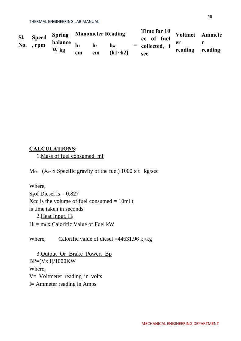
Sl.
No.
Speed
, rpm
Spring
balance
W kg
Manometer Reading Time for 10
cc of fuel
collected, t
sec
Voltmet
er
reading
Ammete
r
reading h1
cm
h2
cm
hw =
(h1~h2)
CALCULATIONS:
1.Mass of fuel consumed, mf
Mf= (Xcc x Specific gravity of the fuel) 1000 x t kg/sec
Where,
Sgof Diesel is = 0.827
Xcc is the volume of fuel consumed = 10ml t
is time taken in seconds
2.Heat Input, HI
HI = mf x Calorific Value of Fuel kW
Where, Calorific value of diesel =44631.96 kj/kg
3.Output Or Brake Power, Bp
BP=(Vx I)/1000KW
Where,
V= Voltmeter reading in volts
I= Ammeter reading in Amps
MECHANICAL ENGINEERING DEPARTMENT
49 THERMAL ENGINEERING LAB MANUAL
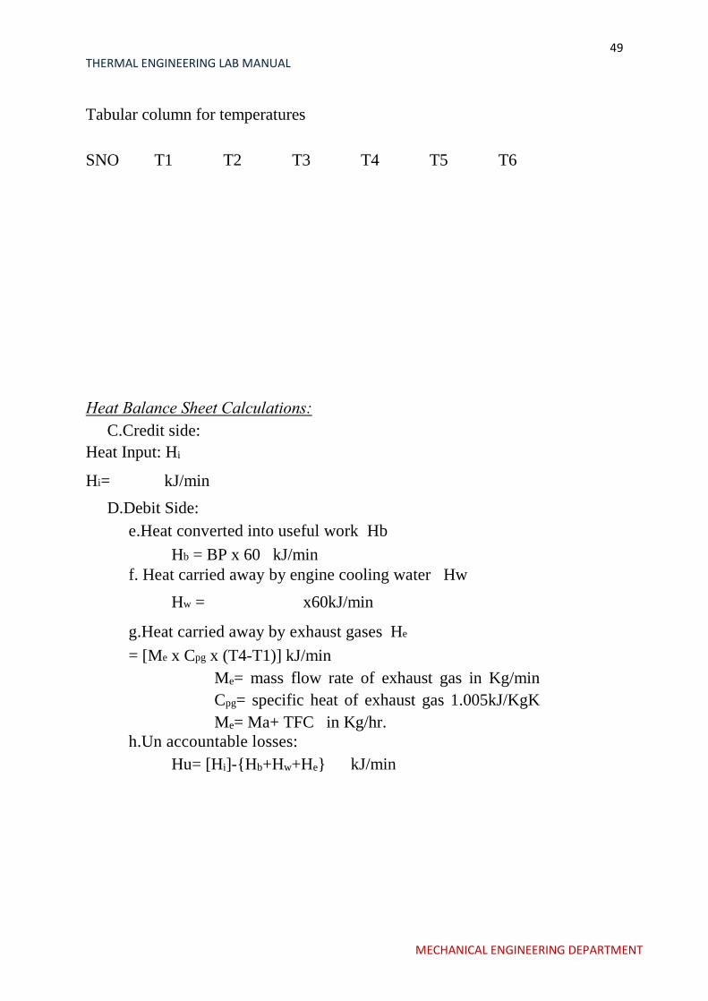
Tabular column for temperatures
SNO T1 T2 T3 T4 T5 T6
Heat Balance Sheet Calculations:
C.Credit side:
Heat Input: Hi
Hi= kJ/min
D.Debit Side:
e.Heat converted into useful work Hb
Hb = BP x 60 kJ/min
f. Heat carried away by engine cooling water Hw
Hw = x60kJ/min
g.Heat carried away by exhaust gases He
= [Me x Cpg x (T4-T1)] kJ/min
Me= mass flow rate of exhaust gas in Kg/min
Cpg= specific heat of exhaust gas 1.005kJ/KgK
Me= Ma+ TFC in Kg/hr.
h.Un accountable losses:
Hu= [Hi]-{Hb+Hw+He} kJ/min
MECHANICAL ENGINEERING DEPARTMENT
50 THERMAL ENGINEERING LAB MANUAL
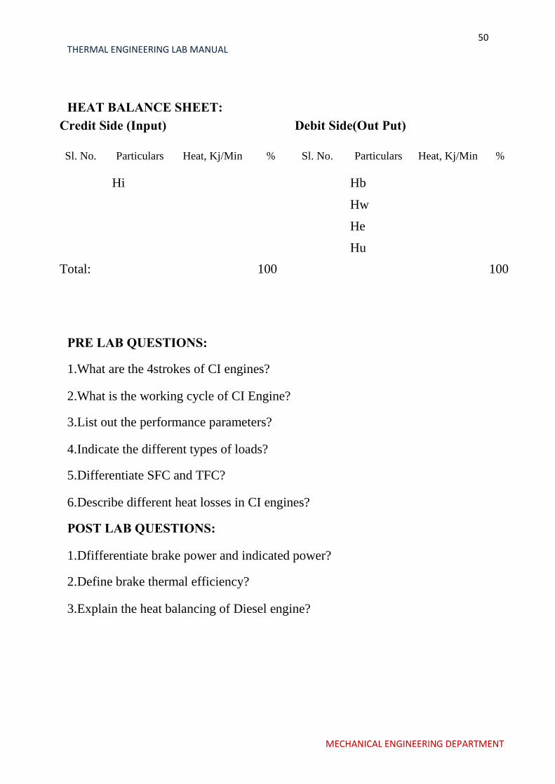
HEAT BALANCE SHEET: Credit Side (Input) Debit Side(Out Put)
Sl. No. Particulars Heat, Kj/Min % Sl. No. Particulars Heat, Kj/Min %
Hi Hb
Hw
He
Hu
Total: 100 100
PRE LAB QUESTIONS:
1.What are the 4strokes of CI engines?
2.What is the working cycle of CI Engine?
3.List out the performance parameters?
4.Indicate the different types of loads?
5.Differentiate SFC and TFC?
6.Describe different heat losses in CI engines?
POST LAB QUESTIONS:
1.Dfifferentiate brake power and indicated power?
2.Define brake thermal efficiency?
3.Explain the heat balancing of Diesel engine?
MECHANICAL ENGINEERING DEPARTMENT

51 THERMAL ENGINEERING LAB MANUAL
EXPERIMENT NO: 9
I C ENGINES AFFECT OF AIR FUEL
RATIO IN A S I ENGINE
MECHANICAL ENGINEERING DEPARTMENT
52 THERMAL ENGINEERING LAB MANUAL
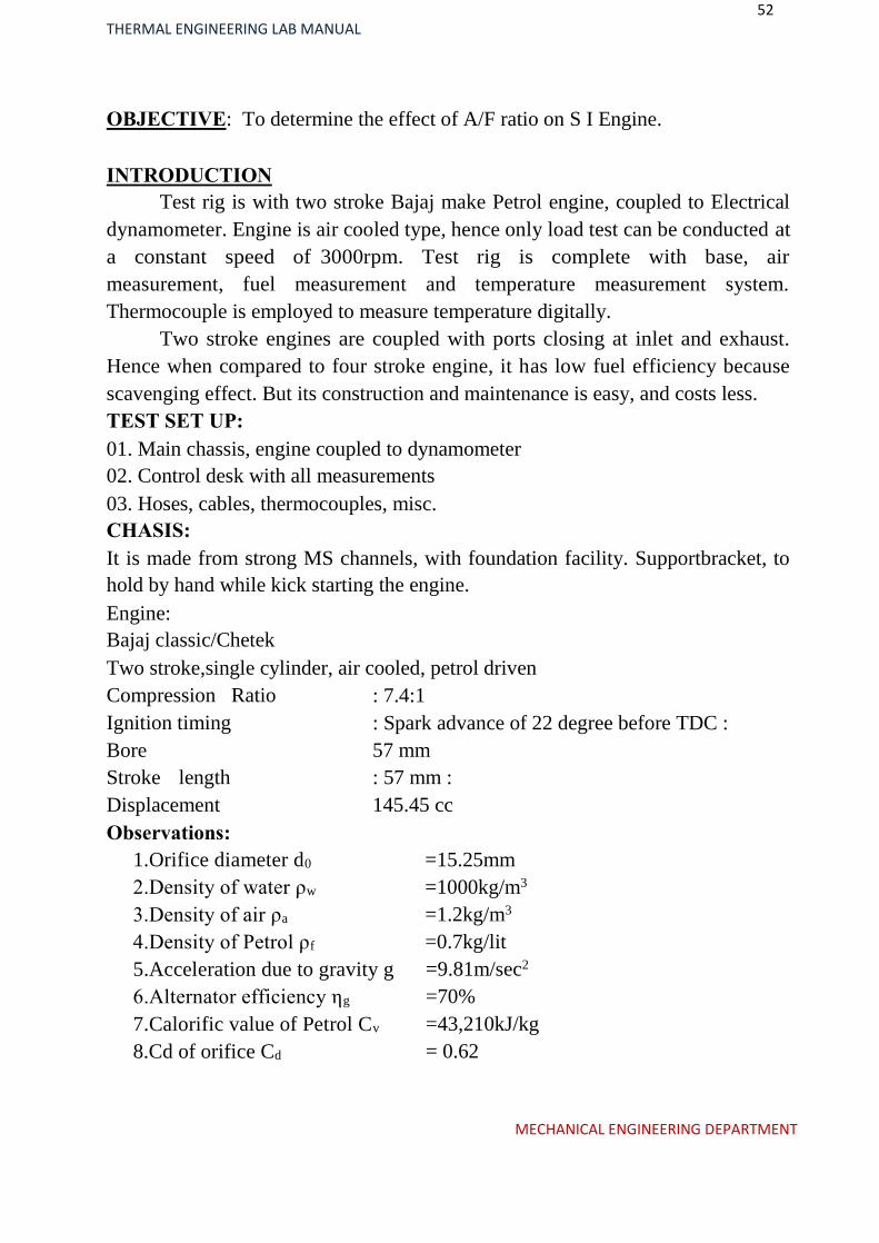
OBJECTIVE: To determine the effect of A/F ratio on S I Engine.
INTRODUCTION
Test rig is with two stroke Bajaj make Petrol engine, coupled to Electrical
dynamometer. Engine is air cooled type, hence only load test can be conducted at
a constant speed of 3000rpm. Test rig is complete with base, air
measurement, fuel measurement and temperature measurement system.
Thermocouple is employed to measure temperature digitally.
Two stroke engines are coupled with ports closing at inlet and exhaust.
Hence when compared to four stroke engine, it has low fuel efficiency because
scavenging effect. But its construction and maintenance is easy, and costs less.
TEST SET UP:
01. Main chassis, engine coupled to dynamometer
02. Control desk with all measurements
03. Hoses, cables, thermocouples, misc.
CHASIS:
It is made from strong MS channels, with foundation facility. Supportbracket, to
hold by hand while kick starting the engine.
Engine:
Bajaj classic/Chetek
Two stroke,single cylinder, air cooled, petrol driven
Compression Ratio
Ignition timing
Bore
Stroke length
Displacement
Observations:
1.Orifice diameter d0
2.Density of water ρw
3.Density of air ρa
4.Density of Petrol ρf
: 7.4:1
: Spark advance of 22 degree before TDC :
57 mm
: 57 mm :
145.45 cc
=15.25mm
=1000kg/m3
=1.2kg/m3
=0.7kg/lit
5.Acceleration due to gravity g
6.Alternator efficiency ηg
7.Calorific value of Petrol Cv
8.Cd of orifice Cd
=9.81m/sec2
=70%
=43,210kJ/kg
= 0.62
MECHANICAL ENGINEERING DEPARTMENT

53 THERMAL ENGINEERING LAB MANUAL
9.Cylinder bore D =57mm
10.Stroke length L =57mm
TABULAR COLUMN:
Sl.
No.
Speed,r
pm
Spring
balance
Wkg
Manometer Reading Time for 10 cc of fuel
collected, t sec h1 cm h2 cm hw = (h1~h2)
PROCEDURE:
1.Fill up water in manometer to required level
2.Ensure petrol level in the fuel tank.
3.Ensure engine oil.
4.Put MCB of alternator to ON,switch of all load bank or bring aluminium
conductor of water loading rheostat above water level.
5.Add water
6.Switch ON ignition
7.Fix accelelrator at some setting
8.Now kick start the engine and when it pickups speed adjust at 3000 rpm
9.at this no load note down manometer,speed ,temperature,voltage current
and time for 10 cc of fuel consumption.
10.Repeat for different loads.
CALCULATIONS:
1.Area of Orifice A0 = d02sq.cm ( d0 is orifice diameter = mm)
2.Manometer Head Ha =( h1-h2) x m (ρw=1000kg/m3)
1.ρa=1.2kg/m3
2.h1 and h2 in m
3.Mass flow rate of Air Ma in kg/hr
MECHANICAL ENGINEERING DEPARTMENT
54 THERMAL ENGINEERING LAB MANUAL
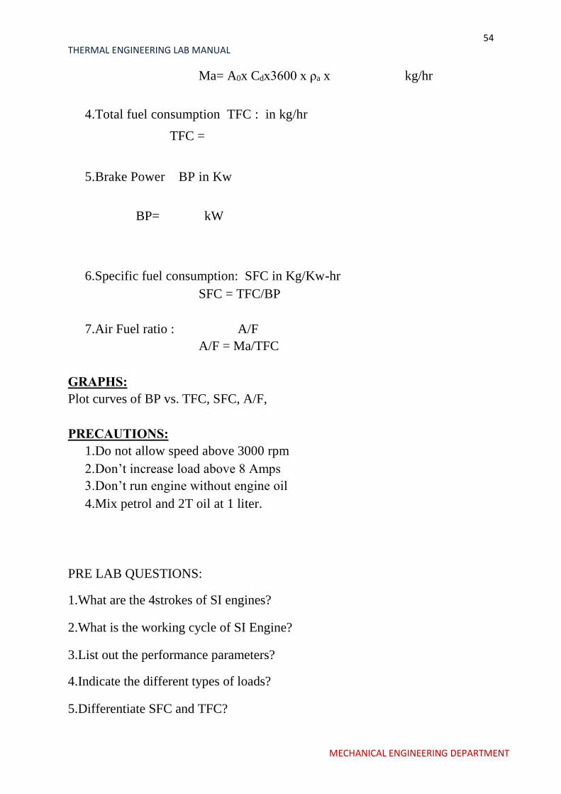
Ma= A0x Cdx3600 x ρa x kg/hr
4.Total fuel consumption TFC : in kg/hr
TFC =
5.Brake Power BP in Kw
BP= kW
6.Specific fuel consumption: SFC in Kg/Kw-hr
SFC = TFC/BP
7.Air Fuel ratio : A/F
A/F = Ma/TFC
GRAPHS:
Plot curves of BP vs. TFC, SFC, A/F,
PRECAUTIONS:
1.Do not allow speed above 3000 rpm
2.Don’t increase load above 8 Amps
3.Don’t run engine without engine oil
4.Mix petrol and 2T oil at 1 liter.
PRE LAB QUESTIONS:
1.What are the 4strokes of SI engines?
2.What is the working cycle of SI Engine?
3.List out the performance parameters?
4.Indicate the different types of loads?
5.Differentiate SFC and TFC?
MECHANICAL ENGINEERING DEPARTMENT
55 THERMAL ENGINEERING LAB MANUAL
6.Define Air -Fuel ratio?
POST LAB QUESTIONS:
1.Dfifferentiate brake power and indicated power?
2.Define brake thermal efficiency?
3.Indicate mechanical efficiency in terms of BP and IP?
4.How the Air-fuel ratio effects the brake thermal efficiency?
MECHANICAL ENGINEERING DEPARTMENT

56 THERMAL ENGINEERING LAB MANUAL
EXPERIMENT NO: 10
PERFORMANCE TEST ON VARIABLE
COMPRESSION RATIO ENGINE
MECHANICAL ENGINEERING DEPARTMENT
57 THERMAL ENGINEERING LAB MANUAL
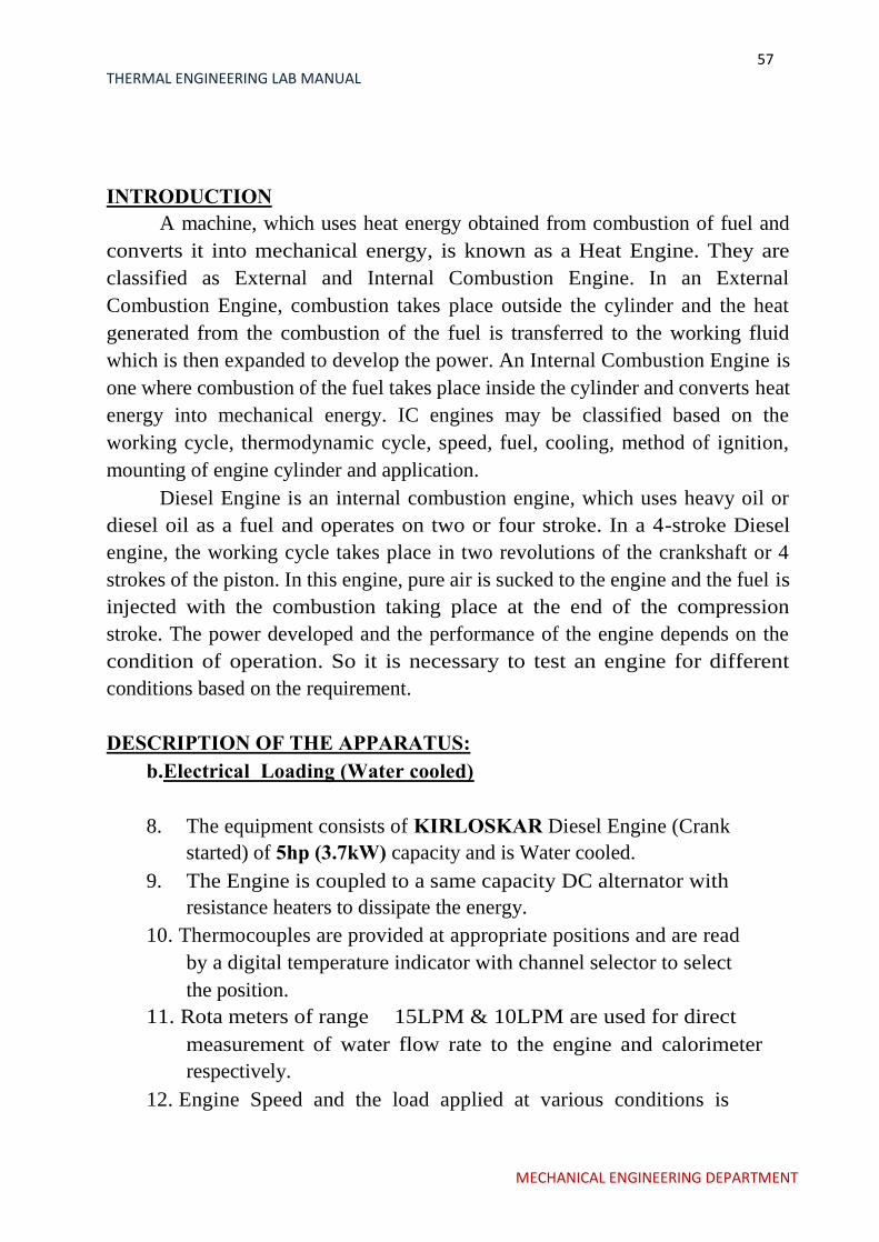
INTRODUCTION
A machine, which uses heat energy obtained from combustion of fuel and
converts it into mechanical energy, is known as a Heat Engine. They are
classified as External and Internal Combustion Engine. In an External
Combustion Engine, combustion takes place outside the cylinder and the heat
generated from the combustion of the fuel is transferred to the working fluid
which is then expanded to develop the power. An Internal Combustion Engine is
one where combustion of the fuel takes place inside the cylinder and converts heat
energy into mechanical energy. IC engines may be classified based on the
working cycle, thermodynamic cycle, speed, fuel, cooling, method of ignition,
mounting of engine cylinder and application.
Diesel Engine is an internal combustion engine, which uses heavy oil or
diesel oil as a fuel and operates on two or four stroke. In a 4-stroke Diesel
engine, the working cycle takes place in two revolutions of the crankshaft or 4
strokes of the piston. In this engine, pure air is sucked to the engine and the fuel is
injected with the combustion taking place at the end of the compression
stroke. The power developed and the performance of the engine depends on the
condition of operation. So it is necessary to test an engine for different
conditions based on the requirement.
DESCRIPTION OF THE APPARATUS:
b.Electrical Loading (Water cooled)
8.
The equipment consists of KIRLOSKAR Diesel Engine (Crank
started) of 5hp (3.7kW) capacity and is Water cooled.
9. The Engine is coupled to a same capacity DC alternator with
resistance heaters to dissipate the energy.
10. Thermocouples are provided at appropriate positions and are read
by a digital temperature indicator with channel selector to select
the position.
11. Rota meters of range 15LPM & 10LPM are used for direct
measurement of water flow rate to the engine and calorimeter
respectively.
12. Engine Speed and the load applied at various conditions is
MECHANICAL ENGINEERING DEPARTMENT

58 THERMAL ENGINEERING LAB MANUAL
determined by a Digital RPM Indicator and spring balance reading.
13. A separate air box with orifice assembly is provided for
regularizing and measuring the flow rate of air. The pressure
difference at the orifice is measured by means of Manometer.
14. A volumetric flask with a fuel distributor is provided for
measurement and directing the fuel to the engine respectively.
EXPERIMENTATION:
AIM: The experiment is conducted to
c)To study and understand the performance characteristics of the
engine.
d)To draw Performance curves and compare with standards.
PROCEDURE:
14.Give the necessary electrical connections to the panel.
15.Check the lubricating oil level in the engine.
16.Check the fuel level in the tank.
17.Allow the water to flow to the engine and the calorimeter and adjust the
flow rate to 6lpm & 3lpm respectively.
18.Release the load if any on the dynamometer.
19.Open the three-way cock so that fuel flows to the engine.
20.Start the engine by cranking.
21.Allow to attain the steady state.
22.Load the engine by slowly tightening the yoke rod handle of the Rope
brake drum.
23.Note the following readings for particular condition,
a.Engine Speed
b.Time taken for ____cc of diesel consumption
c.Rota meter reading.
d.Manometer readings, in cm of water &
e.Temperatures at different locations.
24.Repeat the experiment for different loads and note down the above
readings.
25.After the completion release the load and then switch of the engine.
26.Allow the water to flow for few minutes and then turn it off.
MECHANICAL ENGINEERING DEPARTMENT
59 THERMAL ENGINEERING LAB MANUAL
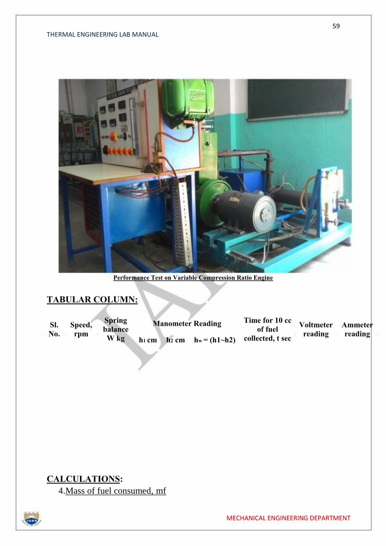
Performance Test on Variable Compression Ratio Engine
TABULAR COLUMN:
Sl. No.
Speed, rpm
Spring
balance
W kg
Manometer Reading Time for 10 cc
of fuel
collected, t sec
Voltmeter reading
Ammeter reading
h1 cm h2 cm hw = (h1~h2)
CALCULATIONS:
4.Mass of fuel consumed, mf
MECHANICAL ENGINEERING DEPARTMENT
60 THERMAL ENGINEERING LAB MANUAL
Mf= (Xcc x Specific gravity of the fuel) 1000 x t kg/sec
Where,
Sgof Diesel is = 0.827
Xcc is the volume of fuel consumed = 10ml t
is time taken in seconds
5. Heat Input, HI
HI = mf x Calorific Value of Fuel kW
Where, Calorific value of diesel =44631.96 kj/kg
6. Output Or Brake Power, Bp
BP=(Vx I)/1000KW
Where,
V= Voltmeter reading in volts I=
Ammeter reading in Amps 7. Specific Fuel
Consumption,Sfc SFC= mfx 3600/BP
kg/KW-hr
8. Brake Thermal Efficiencyղbth%
ղbth% = (3600x 100)/ (SFCx CV)
9. Mechanical Efficiencyղmech%
ղmech% = (BP/IP)x 100
Determine the IP = Indicated power, using WILLAN’S LINE method and yhe
procedure is as below:
Draw the graph of Fuel consumption Vs. Brake power.
Extend the line obtained tillit cuts the brake power axis.
The point where it cuts the brake power axis till the zero point will give
the power losses(Friction Power loss)
With this IP can be found using the relation:
IP = BP+ FP
MECHANICAL ENGINEERING DEPARTMENT
61 THERMAL ENGINEERING LAB MANUAL
10.Calculation Of Head Of Air,Ha
Ha= hw x(ρw/ρa)
Where;
ρw =1000 kg/m³
ρa= 1.2 kg/m³
hw is the head in water column in ‘m’ of water
11.Volumetric Efficiency , ղvol%
ղvol%= (Qa/Qth )x100
where,
Qa = actual volume of air taken = Cdxax
Where Cd= Coefficient of discharge of orifice=0.62
a=area of the orifice= [(π(0.02)²)/4]
Ha =head in air column, m of air.
Qth= theoretical volume of air taken
Qth =
Where
TABULATIONS:
[A= 4
D= Bore diameter of the engine = 0.08m
L= Length of the stroke =0.110m
N is speed of the engine in rpm
Sl. No
Input Power
Output Power
SFC Brake Thermal
Efficiency Mechanical Efficiency
Volumetric efficiency
CALCULATIONS:
2.FRICTION POWER, FP
MECHANICAL ENGINEERING DEPARTMENT
62 THERMAL ENGINEERING LAB MANUAL
FP = (V*I) / 1000 KW
Where,
V= voltmeter reading on motoring side I
= ammeter reading on motoring side
Graphs to be plotted: 1) SFC v/s BP
2) ηbth v/s BP
3)ηmechv/s BP
4) ηvol v/s BP
RESULT:
PRE LAB QUESTIONS:
1.What are the 4strokes of CI engines?
2.What is the working cycle of CI Engine?
3.List out the performance parameters?
4.Indicate the different types of loads?
5.Differentiate SFC and TFC?
6.Concept of mass flow rate of air?
POST LAB QUESTIONS:
1.Dfifferentiate brake power and indicated power?
2.Define brake thermal efficiency?
3.Indicate mechanical efficiency in terms of BP and IP?
4.Determine frictional power by using wilson’s line?
MECHANICAL ENGINEERING DEPARTMENT
63 THERMAL ENGINEERING LAB MANUAL
EXPERIMENT NO: 11
VOLUMETRIC EFFICIENCY OF
A RECIPROCATING AIR
COMPRESSOR
MECHANICAL ENGINEERING DEPARTMENT
64 THERMAL ENGINEERING LAB MANUAL
INTRODUCTION
A COMPRESSOR is a device, which sucks in air at atmospheric
pressure & increases its pressure by compressing it. If the air is compressed in
a single cylinder it is called as a Single StaCompressor. If the air is
compressed in two or more cylinders it is called as a Multi Stage
Compressor.
In a Two Stage Compressor the air is sucked from atmosphere
&compressed in the first cylinder called the low-pressure cylinder. The
compressed air then passes through an inter cooler where its temperature is
reduced. The air is then passed into the second cylinder where it is further
compressed. The air further goes to the air reservoir where it is stored.
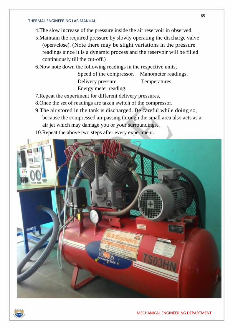
DESCRIPTION OF THE APPARATUS:
1. Consists of Two Stage Reciprocating air compressor of 3hp
capacity. The compressor is fitted with similar capacity Motor as a
driver and 160lt capacity reservoir tank.
2. Air tank with orifice plate assembly is provided to measure the
volume of air taken and is done using the Manometer provided. 3.
Compressed air is stored in an air reservoir, which is provided with a
pressure gauge and automatic cut-off.
4. Necessary Pressure and Temperature tapings are made on the
compressor for making different measurements
5. Temperature is read using the Digital temperature indicator and
speed by Digital RPM indicator.
EXPERIMENTATION:
AIM: The experiment is conducted at various pressures to
a. Determine the Volumetric efficiency.
b. Determine the Isothermal efficiency.
PROCEDURE:
1.Check the necessary electrical connections and also for the
direction of the motor.
2.Check the lubricating oil level in the compressor.
3.Start the compressor by switching on the motor. MECHANICAL ENGINEERING DEPARTMENT
65 THERMAL ENGINEERING LAB MANUAL
4.The slow increase of the pressure inside the air reservoir in observed.
5.Maintain the required pressure by slowly operating the discharge valve
(open/close). (Note there may be slight variations in the pressure
readings since it is a dynamic process and the reservoir will be filled
continuously till the cut-off.)
6.Now note down the following readings in the respective units,
Speed of the compressor. Manometer readings.
Delivery pressure. Temperatures.
Energy meter reading.
7.Repeat the experiment for different delivery pressures.
8.Once the set of readings are taken switch of the compressor.
9.The air stored in the tank is discharged. Be careful while doing so,
because the compressed air passing through the small area also acts as a
air jet which may damage you or your surroundings.
10.Repeat the above two steps after every experiment.
MECHANICAL ENGINEERING DEPARTMENT
66 THERMAL ENGINEERING LAB MANUAL
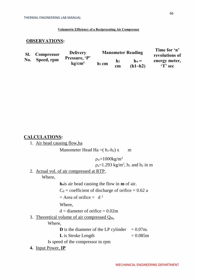
Volumetric Efficiency of a Reciprocating Air Compressor
OBSERVATIONS:
Sl.
No.
Compressor
Speed, rpm
Delivery
Pressure, ‘P’
kg/cm²
Manometer Reading Time for ‘n’
revolutions of
energy meter,
‘T’ sec h1 cm
h2
cm
hw =
(h1~h2)
CALCULATIONS:
1. Air head causing flow,ha
Manometer Head Ha =( h1-h2) x m
ρw=1000kg/m3
ρa=1.293 kg/m3, h1 and h2 in m
2. Actual vol. of air compressed at RTP,
Where,
hais air head causing the flow in m of air.
Cd = coefficient of discharge of orifice = 0.62 a
= Area of orifice = d 2
Where,
d = diameter of orifice = 0.02m
3. Theoretical volume of air compressed Qth,
Where,
D is the diameter of the LP cylinder = 0.07m.
L is Stroke Length = 0.085m
Is speed of the compressor in rpm
4. Input Power, IP
MECHANICAL ENGINEERING DEPARTMENT

67 THERMAL ENGINEERING LAB MANUAL
3600*n*ղm /(KxT)………..kW
Where,
n = No. of revolutions of energy meter (Say 5) K
= Energy meter constant revs/kW-hr T = time for
5 rev. of energy meter in seconds ηm = efficiency of
belt transmission = 75%
5.Isothermal Work done,WD
WD = ρa x QalnrkW
Where,
ρa= is the density of the air = 1.293
kg/m3 Qa = Actual volume of air
compressed.
r = Compression ratio
r = Delivery gauge pressure + Atmospheric
pressure Atmospheric pressure
Where Atmospheric pressure = 101.325 kPa
NOTE: To convert delivery pressure fromkg/cm[ to kPa
multiply by 98.1
6.Volumetric efficiency, ηvol
ηvol = Qa/Qth x 100
7.Isothermal efficiency, ηiso
ηiso= x 100
TABULATIONS: S.
No
Head
of Air
ha, m
Actual
volume of air
compressed
Qa, m3/s
Theoretical
vol of air
compressed
Qth, m3/s
Isothermal
work done
Kw
Iso thermal
efficiency
ηiso, %
Volumetric
Efficiency
ηvol,%
MECHANICAL ENGINEERING DEPARTMENT

68 THERMAL ENGINEERING LAB MANUAL
GRAPHS TO BE PLOTTED:
1. Delivery Pressure vs. ηvol
2. Delivery Pressure vs. ηiso
PRECAUTIONS:
1. Do not run the blower if supply voltage is less than 380V
2. Check the direction of the motor, if the motor runs in
opposite direction change the phase line of the motor to run in
appropriate direction.
3. Do not forget to give electrical earth and neutral
connections correctly.
RESULT:
PRE LAB QUESTIONS:
1.What is the principle of compressor?
2.Differentiate various types of compressors?
3.Explain concept of multi staging?
POST LAB QUESTIONS?
1. Differentiate single stage and multistage compressor?
2. Define isothermal work done?
3.What is isothermal efficiency?
MECHANICAL ENGINEERING DEPARTMENT
69 THERMAL ENGINEERING LAB MANUAL
EXPERIMENT NO:12
DIS-ASSEMBLY/ASSEMBLY OF
I.C. ENGINE
MECHANICAL ENGINEERING DEPARTMENT
70 THERMAL ENGINEERING LAB MANUAL
AIM:
Dismantling and reassembling of a 4 stroke petrol engine.
Apparatus:
Spanner set, Work bench, screw driver, spark plug spanner, spark plug
cleaner, tray, kerosene oil, cotton waste, hammer, oil can etc.
Theory:
In 1878, a British engineer introduced a cycle which could be completed in
two strokes of piston rather than four strokes as is the case with the
four-stroke cycle engines.
In this engine suction and exhaust strokes are eliminated. Here instead of
valves, ports are used. The exhaust gases are driven out from engine
cylinder by the fresh charge of fuel entering the cylinder nearly at the end of
the working stroke.
A two-stroke petrol engine is generally used in scooters, motor cycles etc.
The cylinder L is connected to a closed crank chamber C.C. During the
upward stroke of the piston M, the gases in L are compressed and at the
same time fresh air and fuel (petrol) mixture enters the crank chamber
through the valve.
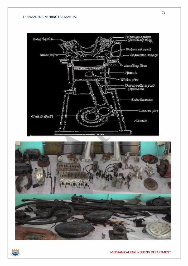
Different Parts of I.C. Engine
Cylinder, Cylinder head, Piston, Piston rings, Gudgeon pin,
Connecting rod, Crankshaft, Crank, Engine bearing, Crank case,
Flywheel etc.
Parts of a 2 Stroke Petrol Engine
Cylinder Head
Also referred to as the top end, the cylinder head houses the pistons,
valves, rocker arms and camshafts.
Valves
A pair of valves, used for controlling fuel intake and exhaust, is controlled by
a set of fingers on the camshaft called lobes. As the intake valve opens, a
mixture of fuel and air from the carburetor is pulled into the cylinder. The
exhaust valve expels the spent air/fuel mixture after combustion.
MECHANICAL ENGINEERING DEPARTMENT
71 THERMAL ENGINEERING LAB MANUAL
MECHANICAL ENGINEERING DEPARTMENT
72 THERMAL ENGINEERING LAB MANUAL
Dis-Assembly/Assembly of I.C. Engine
Camshaft
Usually chain or gear-driven, the camshaft spins, using its lobes to
actuate the rocker arms. These open the intake and exhaust valves at
preset intervals.
The Piston
The piston travels up and down within the cylinder and compresses the
air/fuel mixture to be ignited by a spark plug. The combustive force propels
the piston downward. The piston is attached to a connecting rod by a wrist
pin.
Piston rings:
These are circular rings which seal the gaps made between the piston
and the cylinder, their object being to prevent gas escaping and to control
the amount of lubricant which is allowed to reach the top of the cylinder.
Gudgeon-pin:
This pin transfers the thrust from the piston to the connecting-rod
small-end while permitting the rod to rock to and fro as the crankshaft rotates.
Connecting-rod:
This acts as both a strut and a tie link-rod. It transmits the linear pressure
impulses acting on the piston to the crankshaft big-end journal, where
theyare converted into turning-effort.
Crankshaft
The crankshaft is made up of a left and right flywheel connected to the
piston's connecting rod by a crank pin, which rotates to create the piston's
up-and-down motion. The cam chain sprocket is mounted on the
crankshaft, which controls the chain that drives the camshaft.
The CARBURETTOR
The carburetor is the control for the engine. It feeds the engine with a
mixture of air and petrol in a controlled volume that determines the speed,
acceleration and deceleration of the engine. The carburetor is controlled by a
slide connected to the throttle cable from the handlebar twist grip which
adjusts the volume of air drawn into the engine.
Procedure:
1) Dismantle the following system
a) Fuel supply system
b) Electrical system
MECHANICAL ENGINEERING DEPARTMENT
73 THERMAL ENGINEERING LAB MANUAL
2) Remove the spark plug from the cylinder head.
3) Remove the cylinder head nut and bolts.
4) Separate the cylinder head from the engine block.
5) Remove the carburetor from the engine.
6) Open the crank case.
7) Remove piston rings from the piston.
8) Clean the combustion chamber.
9) Reassemble the components vice versa.
Precautions:
*Don’t use loose handle of hammer.
*Care must be taken while removing the components.
Result:
A 2 - stroke petrol engine has been dismantled and reassembled.
PRE LAB QUESTIONS:
1.List the various components of IC Engine?
2.Describe different materials used for different components?
3.What is the function of carburetor?
POST LAB QUESTIONS:
1.Identifying the different components in IC Engine?
2.Explain working of different parts?
MECHANICAL ENGINEERING DEPARTMENT

74 THERMAL ENGINEERING LAB MANUAL
EXPERIMENT NO:13
STUDY OF BOILERS
MECHANICAL ENGINEERING DEPARTMENT
75 THERMAL ENGINEERING LAB MANUAL
STUDY OF BABCOCK-WILCOX BOILER
Aim: To study Babcock-Wilcox boiler.
Theory: Evaporating the water at appropriate temperatures and pressures in
boilers does the generation of steam. A boiler is defined as a set of units,
combined together consisting of an apparatus for producing and recovering
heat by igniting certain fuel, together with arrangement for transferring
heat so as to make it available to water, which could be heated and
vaporized to steam form. One of the important types of boilers is
Babcock-Wilcox boiler.
Observation: In thermal powerhouses, Babcock Wilcox boilers
degeneration of steam in large quantities.
The boiler consists essentially of three parts.
1.A number of inclined water tubes: They extend all over the
furnace.Water circulates through them and is heated.
2.A horizontal stream and water drum: Here steam separate from
thewater which is kept circulating through the tubes and drum.
3.Combustion chambers: The whole of space where water tubes are laid is
divided into three separate chambers, connected to each other so that hot
gases pass from one to the other and give out heat in each chamber
gradually. Thus the first chamber is the hottest and the last one is at the
lowest temperature. All of these constituents have been shown as in fig.
The Water tubes 76.2 to 109 mm in diameter are connected with each
other and with the drum by vertical passages at each end called Headers.
Tubes are inclined in such a way that they slope down towards theback. The
rear header is called the down-take header and the front header is called
the uptake header has been represented in the fig as DC and VH
respectively.
Whole of the assembly of tubes is hung along with the drum in a room made
of masonry work, lined with fire bricks. This room is divided into
threecompartments A, B, and C as shown in fig, so that first of all, the
hotgases rise in A and go down in B, again rises up in C, and then the led to
the chimney through the smoke chamber C. A mud collector M is attached
to the rear and lowest point of the boiler into which the sediment i.e.
suspended impurities of water are collected due to gravity, during its passage
through the down take header.
Below the front uptake header is situated the grate of the furnace,
MECHANICAL ENGINEERING DEPARTMENT

76 THERMAL ENGINEERING LAB MANUAL
either automatically or manually fired depending upon the size of the
boiler. The direction of hot gases is maintained upwards by the baffles L. In
the steam and water drum the steam is separated from the water and the
remaining water travels to the back end of the drum and descends through
the down take header where it is subjected to the action of fire of which the
temperature goes on increasing towards the uptake header. Then it enters the
drum where the separation occurs and similar process continuous further.
For the purpose of super heating the stream addition sets of
tubesof U-shape fixed horizontally, are fitted in the chamber between the
watertubes and the drum. The steam passes from the steam face of the drum
downwards into the super heater entering at its upper part, and spreads
towards the bottom .Finally the steam enters the water box W, at the bottom
in a super-heated condition from where it is taken out through the outlet
pipes.
The boiler is fitted with the usual mountings like main stop valve
M, safety valve S, and feed valve F, and pressure gauge P. Main stop
valve is used to regulate flow of steam from the boiler, to steam pipe or from
one steam one steam pipe to other.
The function of safety valve is used to safe guard the boiler from the
hazard of pressures higher than the design value. They automatically
discharge steam from the boiler if inside pressure exceeds design-specified
limit.
Feed check valve is used to control the supply of water to the
boiler and to prevent the escaping of water from boiler due to high pressure
inside.
Pressure gauge is an instrument, which record the inside pressure of
the boiler.
When steam is raised from a cold boiler, an arrangement is
provided for flooding the super heater. By this arrangement the super
heater is filled with the water up to the level. Any steam is formed while the
super heater is flooded is delivered to the drum ultimately when it is raised to
the working pressure. Now the water is drained off from the super heater
through the cock provided for this purpose, and then steam is let in for super
heating purposes.
Result: The Babcock - Wilcox boiler is studied.
MECHANICAL ENGINEERING DEPARTMENT
77 THERMAL ENGINEERING LAB MANUAL
STUDY OF LANCASHIRE BOILER
AIM:To study Lancashire boiler.
Theory: Evaporating the water at appropriate temperatures and pressuresin boilers
does the generation of system. A boiler is defined as a set of units, combined together
consisting of an apparatus for producing and recovering heat by igniting certain fuel,
together with arrangement for transferring heat so as to make it available to water,
which could be heated and vaporized to steam form. One of the important types of
boilers is Lancashire boiler.
Observation: Lancashire boiler has two large diameter tubes called flues,through
which the hot gases pass. The water filled in the main shell is heated from within
around the flues and also from bottom and sides of the shell, with the help of other
masonry ducts constructed in the boiler as described below.
The main boiler shell is of about 1.85 to 2.75 m in diameter and about 8 m long.
Two large tubes of 75 to 105 cm diameter pass from end to end through this shell.
These are called flues. Each flue is proved with a firedoorand a grate on the front end.
The shell is placed in a placed in amasonry structure which forms the external flues
through which, also, hot gases pass and thus the boiler shell also forms a part of the
heating surface. The whole arrangement of the brickwork and placing of boiler shell
and flues is as shown in fig.
SS is the boiler shell enclosing the main flue tubes. SF is the side flues running
along the length of the shell and BF is the bottom flue.Side and bottom flues are the
ducts, which are provided in masonry itself.
The draught in this boiler is produced by chimney. The hot gases starting from the
grate travel all along the flues tubes; and thus transmits heat through the surface of the
flues. On reaching at the back end of the boiler they go down through a passage,
they heat water through the lower portion of the main water shell. On reaching
again at front end they bifurcate to the side flues and travel in the forward direction till
finally they reach in the smoke chamber from where they pass onto chimney.
During passage through the side flues also they provide heat to the water
through a part of the main shell. Thus it will be seen that sufficient amount of area is
provided as heating surface by the flue tubes and by a large portion of the shell
Operating the dampers L placed at the exit of the flues may regulate the flow of the
gases. Suitable firebricks line the flues. The boiler is equipped with suitable
MECHANICAL ENGINEERING DEPARTMENT

78 THERMAL ENGINEERING LAB MANUAL
Study of Lancashire Boiler
Firebricks line the flues. The boiler is equipped with suitable mountings and
accessories.
There is a special advantage possessed by such types of boilers. The products of
combustion are carried through the bottom flues only after they have passed
through the main flue tubes, hence the hottest portion does not lie in the bottom of the
boiler, where the sediment contained in water as impurities is likely to fall. Therefore
there are less chances of unduly heating the plates at the bottom due to these
sediments.
Result: The Lancashire boiler is studied.
PRE LAB QUESTIONS:
1.What is the function of boiler?
2.What are the different types of boilers?
3.Explain the terms used for boilers?
4.Differentiate water tube and fire tube boilers? MECHANICAL ENGINEERING DEPARTMENT
79 THERMAL ENGINEERING LAB MANUAL
POST LAB QUESTIONS:
1.Explain the working principles of various boilers?
2.Advantages of high pressure boilers?
MECHANICAL ENGINEERING DEPARTMENT