thermal design of heat exchangers - kth
TRANSCRIPT

i
Helsinki University of Technology Department of Mechanical Engineering
Energy Engineering and Environmental Protection Publications
Steam Boiler Technology eBook
Espoo 2002
Thermal Design of Heat Exchangers Sebastian Teir, Anne Jokivuori
Helsinki University of Technology
Department of Mechanical Engineering
Energy Engineering and Environmental Protection
ii
Table of contents Table of contents..................................................................................................................................ii General design issues ...........................................................................................................................1
Heat transfer modes .........................................................................................................................1 Conduction ...................................................................................................................................1 Convection ...................................................................................................................................1 Radiation ......................................................................................................................................2
Pressure losses..................................................................................................................................2 Definition .....................................................................................................................................2 Gas side pressure drop for inline tube arrangement.....................................................................3 Gas side pressure drop for staggered tube arrangement ..............................................................3
Choice of tube surface......................................................................................................................4 Sizing of heat transfer surfaces ........................................................................................................4
Furnace design .....................................................................................................................................6 General design..................................................................................................................................6 Furnace strain level ..........................................................................................................................7 Tube wall design ..............................................................................................................................8 Load characteristics..........................................................................................................................8 Fuel type effect on furnace size .......................................................................................................8 Typical furnace outlet temperatures.................................................................................................9 Furnace air levels ...........................................................................................................................10 CFB furnace design........................................................................................................................10 BFB furnace design........................................................................................................................12 Heat recovery steam generator (HRSG) design.............................................................................12 Furnace dimensioning, stirred reactor............................................................................................14
Superheater design .............................................................................................................................15 General ...........................................................................................................................................15 Design velocity ..............................................................................................................................15 Design spacing ...............................................................................................................................16 Tube arrangement ..........................................................................................................................17
Economizer design.............................................................................................................................18 General ...........................................................................................................................................18 Design method ...............................................................................................................................18
Air preheater design ...........................................................................................................................21 References ..........................................................................................................................................22
1
General design issues
Heat transfer modes
Conduction Conduction is the transfer of heat from one part of a body at a higher temperature to another part of the same body at a lower temperature, or from one body at a higher temperature to another body in physical contact with it at a lower temperature. The conduction process takes place at the molecular level and involves the transfer of energy from the more energetic molecules to those with a lower energy level. Heat power [W] by conduction is:
sttA 21 −=Φ λ (1)
Heat power depends on the heat transfer area (A), temperature difference (t1-t2), thermal conductivity of material (λ) and the thickness of separating wall (s). The thermal conductivity is a property of the material; metals conduct well heat whereas gases not. An example of thermal conductivities in various materials is shown in table 1.
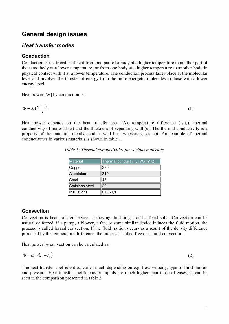
Table 1: Thermal conductivities for various materials.
Material Thermal conductivity [W/(m*K)] Copper 370 Aluminium 210 Steel 45 Stainless steel 20 Insulations 0,03-0,1
Convection Convection is heat transfer between a moving fluid or gas and a fixed solid. Convection can be natural or forced: if a pump, a blower, a fan, or some similar device induces the fluid motion, the process is called forced convection. If the fluid motion occurs as a result of the density difference produced by the temperature difference, the process is called free or natural convection. Heat power by convection can be calculated as:
( )21 ttAc −=Φ α (2) The heat transfer coefficient αc varies much depending on e.g. flow velocity, type of fluid motion and pressure. Heat transfer coefficients of liquids are much higher than those of gases, as can be seen in the comparison presented in table 2.

2
Table 2: Convection heat transfer coefficients for various fluids.
Fluid Heat transfer coefficient [W/(m2K)] Steady water 100-500 Water flow 500-10000 Water boiling 1000-60000 Steady air 3-15 Air flow 10-100
Radiation Radiation, or more correctly thermal radiation, is electromagnetic radiation emitted by a body by virtue of its temperature and at the expense of its internal energy. All heated solids and liquids, as well as some gases, emit thermal radiation. The importance of radiation heat transfer will increase, when the temperature becomes higher. Radiation heat transfer is the main heat transfer mode for the furnace and radiation superheaters. Emitted heat by radiation can be calculated as:
)( 44wffwr TTA −=Φ σε (3)
where εfw is the view factor between the flame and the water walls:
1111
−+=
wf
fw
εε
ε (4)
where εf is the emissivity of the flame (typically 0,35-0,85), εw the emissivity of the water walls (typically 0,6), σ the Stefan-Boltzmann constant (5,6787*10-8 W/m2K4), A the effective water wall surface (m2), Tf the average gas temperature in the furnace and Tw the average water wall surface temperature surrounding the flame. Radiation heat can also be expressed as
( )21 ttArad −=Φ α (5) where αrad is the radiation heat transfer coefficient.
Pressure losses
Definition The difference between pressure gage readings in parts of a system operating with a positive pressure relative to that of the atmosphere is generally called pressure drop. The pressure drop on the gas side is equal to the friction losses, according to VDI Wärmeatlas [1]:
fgs p = p ∆∆ (6)
3
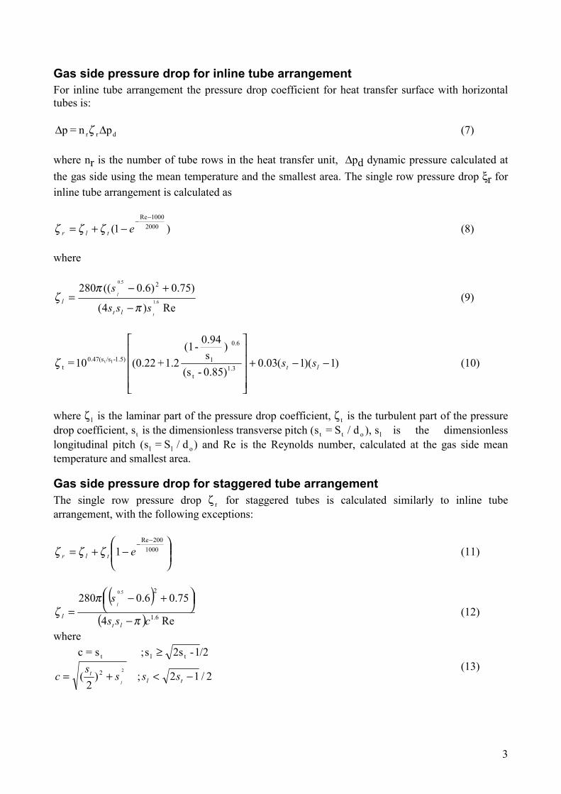
Gas side pressure drop for inline tube arrangement For inline tube arrangement the pressure drop coefficient for heat transfer surface with horizontal tubes is:
drr pn = p ∆∆ ζ (7) where nr is the number of tube rows in the heat transfer unit, ∆pd dynamic pressure calculated at the gas side using the mean temperature and the smallest area. The single row pressure drop ξr for inline tube arrangement is calculated as
)1( 20001000Re−
−−+= etlr ζζζ (8)
where
Re)4(
)75.0)6.0((2806.1
5.0 2
t
l
sss
s
ltl
π
πζ
−
+−= (9)
)1)(1(03.0 0.85)-(s
) s
0.94-(1 1.2+(0.2210 = 1.3
t
0.6
l1.5)-/s0.47(st
lt −−+
lt ssζ (10)
where ζ l is the laminar part of the pressure drop coefficient, ζ t is the turbulent part of the pressure drop coefficient, st is the dimensionless transverse pitch (s = S / dt t o ), sl is the dimensionless longitudinal pitch (s = S / dl l o ) and Re is the Reynolds number, calculated at the gas side mean temperature and smallest area.
Gas side pressure drop for staggered tube arrangement The single row pressure drop ζ r for staggered tubes is calculated similarly to inline tube arrangement, with the following exceptions:
−+=
−−
1000200Re
1 etlr ζζζ (11)
( )( ) Re4
75.06.02806.1
25.0
css
s
ltl
l
π
πζ
−
+−= (12)
where
2/12;)2
(
/21-2ss;s=c22
tlt
−<+=
≥
tlt sss
sc
l
(13)

4
( )
33
08.1 101.014.085.02.15.2
−−
−+
−+=
l
t
t
l
tt s
sss
sζ (14)
Choice of tube surface Surfaces used in tubular heat transfer units can be finned or unfinned (smooth surface). Heat transfer properties can be improved using finned tubes, because the fins enlarge the tubular heat transfer area. The tubes in the economizer are usually finned, because the heat transfer properties of the flue gas side are not so good as on the water side. Economizers are made of cast iron or steel tubes. Cast iron tubes are easily equipped with fins, but also steel tubes can be equipped with fins. Finned tubes are more difficult to clean than unfinned tubes, thus economizers with unfinned steel tubes are used in boilers burning fuels with a high ash content. Figures 1-3 provide some examples on finned steel tubes. Spiral finned tubes are often used in heat recovery steam generators. By bending fins heat transfer properties can also be improved. Steel tube with aluminium fins endures better in corrosive conditions. Compound composition conists of a cast iron tube equipped with fins and steel tube inside. A compound composistion endures higher pressure. In air preheaters finned steel tubes are not used, since the heat transfer properties are practically the same on both air and flue gas sides. When cast iron tubes are used, heat transfer surfaces are usually finned on both sides to improve the heat transfer. Superheaters and evaporators use unfinned tubes.
Sizing of heat transfer surfaces When sizing the heat transfer surface of a heat exchanger the heat power to be transferred and stream temperatures of inlets and outlets have to be known. The heat power is proportional to the area of the heat exchanger, heat transmission coefficient and temperature difference (between the streams):
Figure 1: Spiral finned tubes [Aircoil].
Figure 2: Finned tubes [Vulcan finned tubes].
5
lmTkA∆=Φ (15) The mean logarithmic temperature difference in equation 15 can be calculated as:
min
max
minmax
lnTT
TTTlm
∆∆
∆−∆=∆ (16)
where ∆Tmax is the largest temperature difference and ∆Tmin the smallest temperature difference:
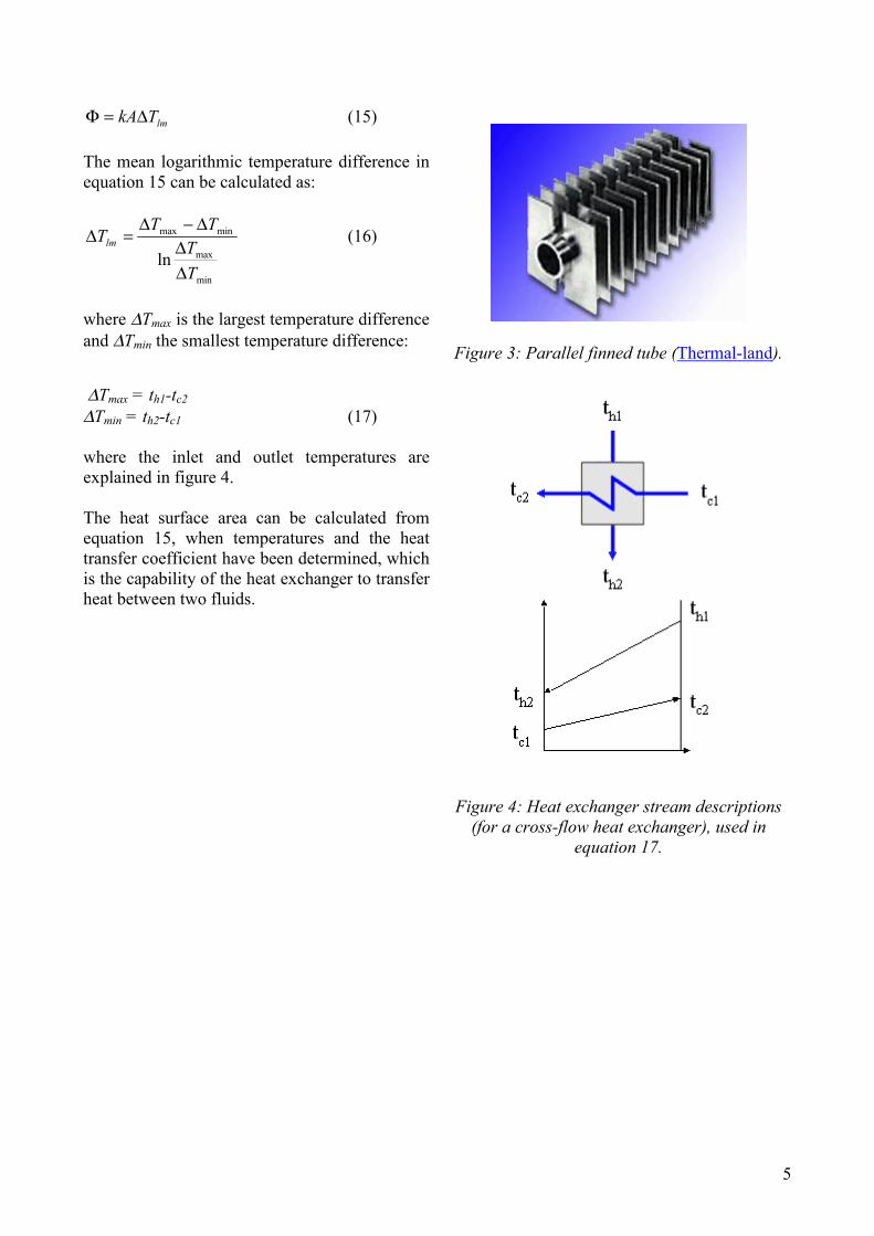
Figure 3: Parallel finned tube (Thermal-land).
∆Tmax = th1-tc2 ∆Tmin = th2-tc1 (17) where the inlet and outlet temperatures are explained in figure 4. The heat surface area can be calculated from equation 15, when temperatures and the heat transfer coefficient have been determined, which is the capability of the heat exchanger to transfer heat between two fluids.
Figure 4: Heat exchanger stream descriptions
(for a cross-flow heat exchanger), used in equation 17.

6
Furnace design
General design The main parameters for the furnace sizing are furnace dimensions (height, depth, width and configuration), furnace wall construction and desired furnace outlet temperature. The heat transfer surface area of furnace consists of sides, base and beak, which is an "L"-formed bending of the evaporator tubes that protect the superheaters from radiation. Most of utility and industrial boiler furnaces have a rectangular shape. A large number of package boilers have a cylindrical furnace. Furnace bottom for typical PCF boiler is double inclined or v-form, as shown in figure 5. Flat bottom is more typical for grate or bubbling fluidized bed boilers. The ratio of height and width varies 1-5 for boilers with two-pass layout. The larger the boiler is, the larger is also the ratio. The largest boilers have a width of 20 m and a height of 100 m. The fuel and vaporization efficiency determines the size of the furnace. To be able to dimension furnaces the overall mass balance, heat balance and heat transfer must be specified. The overall furnace (gas side) mass balance is
ashfiairfg mmmm &&&& −+= ∑ (18) where the streams are described in figure 6. ∑ fim& is the sum of all the fuel streams into the boiler. The furnace heat balance can be specified similarly:
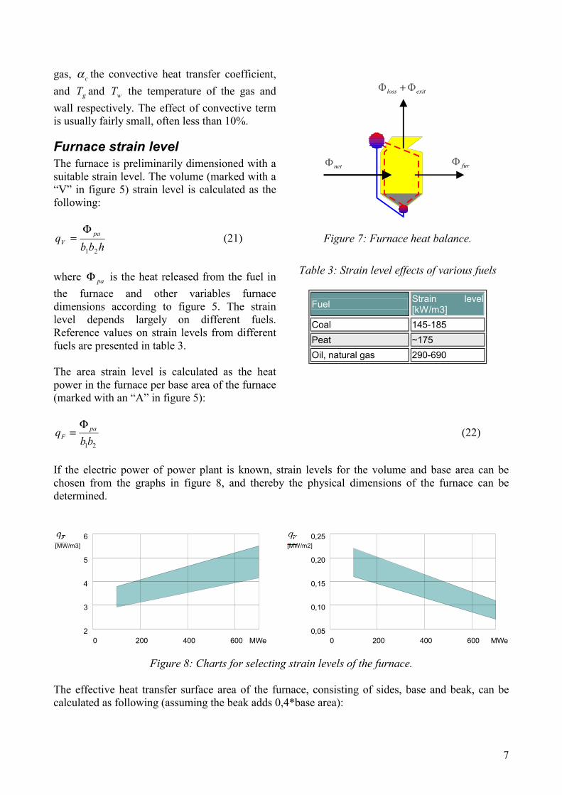
exitlossnetfur Φ−Φ−Φ=Φ (19) where the heat fluxes are shown in figure 7. If the gas side temperatures and emissivities are known, the furnace heat flux absorbed by the furnace walls can be expressed as
( )wgeffcwdg
gdgwdgwdg
wefffur
TTAT
TA
−⋅⋅+−
⋅−+
⋅⋅=Φ
αα
εεαεα
εσ
)
(
4
4
(20)
where Aeff is the effective heat transfer surface, σ the Stefan-Boltzmann constant, wε and dgε the emissivity of the wall and the (dusty) gas respectively, dgα the absorptivity of the (dusty)
h
b2b1
V
A
Figure 5: Furnace dimensions. The painted areas are the total effective furnace heat
transfer area.
fgm&
airm&
fim&
ashm&
Figure 6: Fuel/flue gas side mass balance.
7
gas, cα the convective heat transfer coefficient, and gT and wT the temperature of the gas and wall respectively. The effect of convective term is usually fairly small, often less than 10%.
Furnace strain level The furnace is preliminarily dimensioned with a suitable strain level. The volume (marked with a “V” in figure 5) strain level is calculated as the following:
hbbq pa
V21
Φ= (21)
where paΦ is the heat released from the fuel in the furnace and other variables furnace dimensions according to figure 5. The strain level depends largely on different fuels. Reference values on strain levels from different fuels are presented in table 3. The area strain level is calculated as the heat power in the furnace per base area of the furnace (marked with an “A” in figure 5):
fur
exitloss
net
Figure 7: Furnace heat balance.
Table 3: Strain level effects of various fuels
Fuel Strain level [kW/m3]
Coal 145-185 Peat ~175 Oil, natural gas 290-690
21bbq pa
F
Φ= (22)
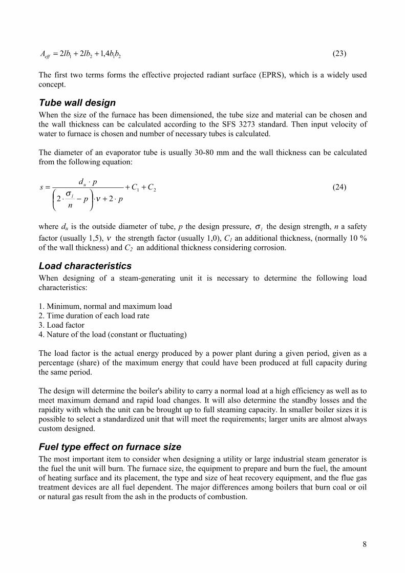
If the electric power of power plant is known, strain levels for the volume and base area can be chosen from the graphs in figure 8, and thereby the physical dimensions of the furnace can be determined.
6
5
4
3
2
[MW/m3]0,25
0,20
0,15
0,10
0,05
[MW/m2]
0 200 400 600 MWe 0 200 400 600 MWe
Figure 8: Charts for selecting strain levels of the furnace. The effective heat transfer surface area of the furnace, consisting of sides, base and beak, can be calculated as following (assuming the beak adds 0,4*base area):
8
2121 4,122 bblblbAeff ++= (23) The first two terms forms the effective projected radiant surface (EPRS), which is a widely used concept.
Tube wall design When the size of the furnace has been dimensioned, the tube size and material can be chosen and the wall thickness can be calculated according to the SFS 3273 standard. Then input velocity of water to furnace is chosen and number of necessary tubes is calculated. The diameter of an evaporator tube is usually 30-80 mm and the wall thickness can be calculated from the following equation:
21
22CC
ppn
pdsl
u ++⋅+⋅
−⋅
⋅=
νσ
(24)
where du is the outside diameter of tube, p the design pressure, lσ the design strength, n a safety factor (usually 1,5), ν the strength factor (usually 1,0), C1 an additional thickness, (normally 10 % of the wall thickness) and C2 an additional thickness considering corrosion.
Load characteristics When designing of a steam-generating unit it is necessary to determine the following load characteristics: 1. Minimum, normal and maximum load 2. Time duration of each load rate 3. Load factor 4. Nature of the load (constant or fluctuating) The load factor is the actual energy produced by a power plant during a given period, given as a percentage (share) of the maximum energy that could have been produced at full capacity during the same period. The design will determine the boiler's ability to carry a normal load at a high efficiency as well as to meet maximum demand and rapid load changes. It will also determine the standby losses and the rapidity with which the unit can be brought up to full steaming capacity. In smaller boiler sizes it is possible to select a standardized unit that will meet the requirements; larger units are almost always custom designed.
Fuel type effect on furnace size The most important item to consider when designing a utility or large industrial steam generator is the fuel the unit will burn. The furnace size, the equipment to prepare and burn the fuel, the amount of heating surface and its placement, the type and size of heat recovery equipment, and the flue gas treatment devices are all fuel dependent. The major differences among boilers that burn coal or oil or natural gas result from the ash in the products of combustion.

9
Firing oil in the furnace produces relatively small amounts of ash. Natural gas produces no ash. For the same power output, due to the high ash content of coal, coal-burning boilers must have larger furnaces and velocities of the combustion gases in the convection-based heat exchangers must be lower. Figure 9 presents an example of the relative sizes of furnaces using three different fuels: natural gas, oil and coal. The power of the boiler is the same in all three cases.
h
b21,05*b1
1,2*h
1,5*h
b1
1,06*b21,1*b1
1,12*b2
Oil
Natural gas
Coal
Figure 9: Boiler fuel type effect on furnace size.
Typical furnace outlet temperatures Furnace outlet temperature is the flue gas temperature after the radiation-based heat transfer surfaces before entering the convection-based heat transfer surfaces. The outlet temperature depends on the characteristics of the combusted fuel. If the temperature is too high, ash layers build up on the surface of the superheater tubes. This leads to poorer heat transfer, increased corrosion and it can even block flow paths. The following factors affect the choice of furnace outlet temperature:
• Ash characteristics; the control of ash behaviour at superheaters is a key design parameter • Fuel (gas and oil have low ash content and can have higher outlet temperatures) • Choice of superheater material • Desired superheating temperature

10
Table 4 presents some typical furnace outlet temperatures:
Table 4: Typical furnace outlet temperatures on various boiler types.
Fuel type Furnace outlet temperature [°C] Biomass, circulating fluidized bed 900 - 1000 Peat, pulverized firing 950 - 1000 Coal, high volatiles 950 - 1000 Recovery boiler 900- 1050 Biomass, fluidized bed 1050 - 1150 Natural gas 900- 1200 Oil 900- 1200
Furnace air levels The type of fuel determines the quantity of air required for combustion. It is necessary to provide air in excess of this quantity to assure complete combustion. The amount of this excess air is determined by the following factors: 1. Composition, properties, and condition of fuel when fired 2. Method of burning the combustible 3. Arrangement and proportions of the grate or furnace 4. Allowable furnace temperature 5. Turbulence and thoroughness of the mixing of combustion air and volatile gases Excess air reduces efficiency by lowering the furnace temperature and by absorbing heat that would otherwise be available for steam production. NOx is formed when nitrogen of air reacts with oxygen of air in high temperature, over 1400 °C. NOx can be reduced decreasing temperature, decreasing air excess, or using low-nox-burners. In using low-nox-burner air will be fed into flame in two or three phases.
CFB furnace design When dimensioning a circulating fluidized bed (CFB) furnace the high content of sand has to be taken into consideration. This means that the temperature profile and thus the heat transfer near to the furnace wall differs from other types of furnaces. The furnace of a CFB (circulating fluidized bed) boiler contains a layer of granular solids, which have a diameter in the range of 0,1-0,3 mm. It includes sand or gravel, fresh or spent limestone and ash. The operating velocity of the flue gas stream in a CFB boiler is 3-10 m/s. The solids move through the furnace at much lower velocity than the gas; solids residence times in the order of minutes are obtained. The long residence times coupled with the small particle size produce high combustion efficiency and high SO2 removal with much lower limestone feed than in conventional furnaces. Figure 10 shows a flow chart of a typical CFB boiler. After the furnace flue gas moves through a cyclone (named compact separator in figure 13), where solids are separated from the gas and are returned to the furnace. Flue gas from the cyclone discharge enters the convection back-pass in which the superheaters, reheaters, economizers and air preheaters are located. A dust collector is separates the fly ash before the flue gas exits the plant.

11
The combustion air from the fan discharges pneumatically transports the solids for creating the circulating fluid.
Fuel
Steam Drum
SteamWater
Steam Outlet
To Ash Silos
Fly Ash
Feed Water InletDust Collector
Induced DraftFan
Primary Air FanSecondary Air Fan
Economizer
Downcomer
CombustionChamber
BottomAsh
Limestone
WaterWall
Air heater
Compact Separator
compact.eng/comflow.ds4/0801/tap
Foster Wheeler CFB Flow Chart
Figure 10: Flow chart of a CFB boiler [Foster-Wheeler].
The design of the furnace in a CFB boiler depends on:
• required velocity of gas • time of complete combustion of fuel • heat required for vaporization.
The amount of cyclones also has an influence on the shape of furnace. Flue gas must flow to the cyclone fast enough (20 m/s), and the diameter of the cyclone must be below 8 m in order to get an efficient removal of solids. Circulating fluidized bed boilers have a number of unique features that make them more attractive than other solid fuel fired boilers. Fuel flexibility is one of the major attractive features of CFB boilers. A wide range of fuels can be burned in one specific boiler without any major change in the hardware. The combustion efficiency of a CFB boiler is high. It is generally in the range of 99,5 to 97,5 %. Sulphur capture in a CFB is very efficient, due to the possibility to inject sulphur absorbing limestone directly into the bed. A typical CFB boiler can capture 90 % of the sulphur dioxide. The low emission of nitrogen oxides is also a major attractive feature of CFB boilers.
12
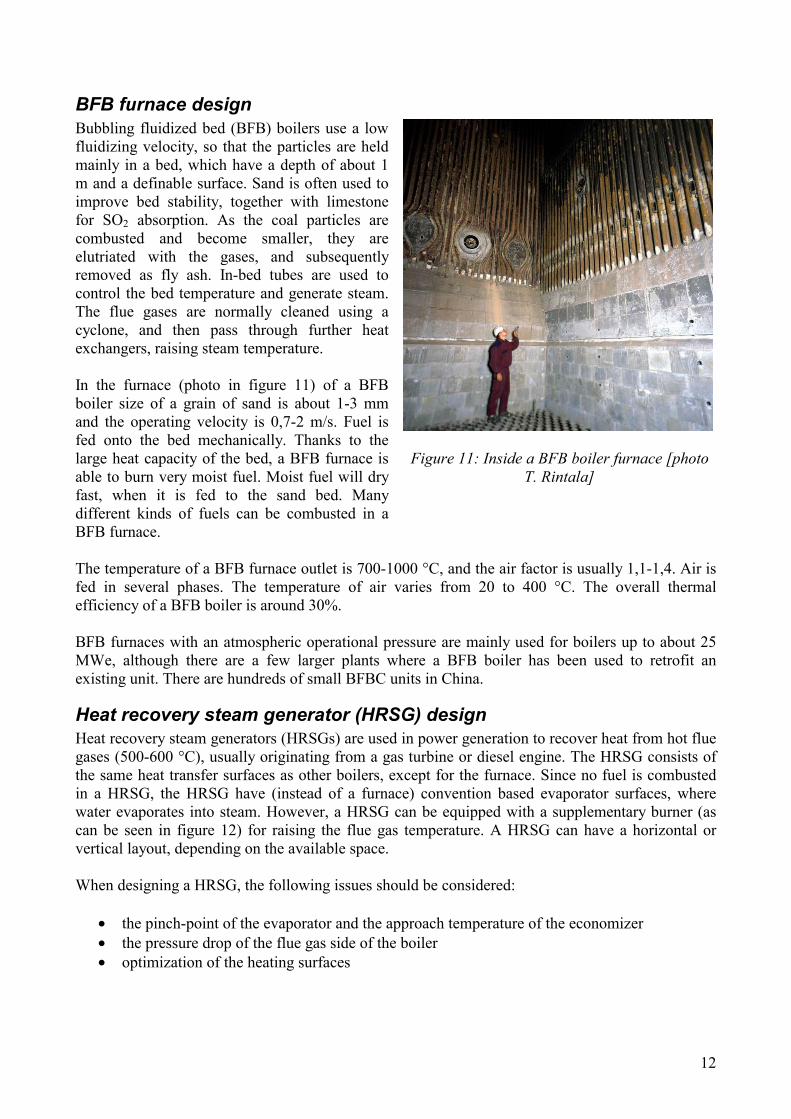
BFB furnace design Bubbling fluidized bed (BFB) boilers use a low fluidizing velocity, so that the particles are held mainly in a bed, which have a depth of about 1 m and a definable surface. Sand is often used to improve bed stability, together with limestone for SO2 absorption. As the coal particles are combusted and become smaller, they are elutriated with the gases, and subsequently removed as fly ash. In-bed tubes are used to control the bed temperature and generate steam. The flue gases are normally cleaned using a cyclone, and then pass through further heat exchangers, raising steam temperature. In the furnace (photo in figure 11) of a BFB boiler size of a grain of sand is about 1-3 mm and the operating velocity is 0,7-2 m/s. Fuel is fed onto the bed mechanically. Thanks to the large heat capacity of the bed, a BFB furnace is able to burn very moist fuel. Moist fuel will dry fast, when it is fed to the sand bed. Many different kinds of fuels can be combusted in a BFB furnace.
Figure 11: Inside a BFB boiler furnace [photo
T. Rintala]
The temperature of a BFB furnace outlet is 700-1000 °C, and the air factor is usually 1,1-1,4. Air is fed in several phases. The temperature of air varies from 20 to 400 °C. The overall thermal efficiency of a BFB boiler is around 30%. BFB furnaces with an atmospheric operational pressure are mainly used for boilers up to about 25 MWe, although there are a few larger plants where a BFB boiler has been used to retrofit an existing unit. There are hundreds of small BFBC units in China.
Heat recovery steam generator (HRSG) design Heat recovery steam generators (HRSGs) are used in power generation to recover heat from hot flue gases (500-600 °C), usually originating from a gas turbine or diesel engine. The HRSG consists of the same heat transfer surfaces as other boilers, except for the furnace. Since no fuel is combusted in a HRSG, the HRSG have (instead of a furnace) convention based evaporator surfaces, where water evaporates into steam. However, a HRSG can be equipped with a supplementary burner (as can be seen in figure 12) for raising the flue gas temperature. A HRSG can have a horizontal or vertical layout, depending on the available space. When designing a HRSG, the following issues should be considered:
• the pinch-point of the evaporator and the approach temperature of the economizer • the pressure drop of the flue gas side of the boiler • optimization of the heating surfaces

13
The pinch-point (the smallest temperature difference between the two streams in a system of heat exchangers) is found in the evaporator, and is usually 6-10 °C, which can be seen in figure 13. To maximize the steam power of the boiler, the pinch-point must be chosen as small as possible. The approach temperature is the temperature difference of the input temperature in the evaporator and the output of the economizer. This is often 0-5 °C. The pressure drop (usually 25-40 mbar) of the flue gas side has also an effect on the efficiency of power plant. The heat transfer of the HRSG is primarily convective. The flow velocity of the flue gas has an influence on the heat transfer coefficient.
The evaporator of heat recovery boiler can be of natural or forced circulation type. The heat exchanger type of the evaporator can be any of parallel-flow, counter-flow or cross-flow. In parallel-flow arrangement the hot and cold fluids move in the same direction and in counter-flow heat exchanger fluids move in opposite direction.
Flue GasOUT
Flue GasIN
FuelIN
HP SteamOUT
FeedwaterIN
Superheater
Evaporator
Economizer
Supplementary burner
Figure 12: Process scheme of single-pressure HRSG with a supplementary burner.
Heating surfaces of a heat recovery steam generator are usually heat transfer packages, which consist of spiral-finned tubes. The thickness of the fin is 1-2 mm, the height 8-16 mm and the fin distance 3,2-8 mm. Tube sizes vary a lot.
0
100
200
300
400
500
600
700
0 % 10 % 20 % 30 % 40 % 50 % 60 % 70 % 80 % 90 % 100 %
Share of heat load [%]
Tem
pera
ture
[°C
]
F lu e g a s s tre a m
Water/steam stream
EvaporatorSuperheater Economizer
Figure 13: Example of a heat load graph for a HRSG boiler.

14
Furnace dimensioning, stirred reactor One of the most used furnace dimensioning methods is the stirred reactor model. The furnace is approximated as being filled with a homogenous three-atom gas and a dust mixture at a uniform temperature and pressure. At the furnace exit the temperature is decreased by a specified amount. The stirred reactor furnace dimensioning process is as follows: 1. Guess initial furnace dimensions; shape, height, width, depth 2. Guess furnace exit temperature, Texit 3. Calculate heat transfer using flue gas temperature Tfg = Texit+∆T 4. Calculate furnace exit temperature from heat balance with calculated heat transfer 5. If the mode does not converge, then return to step 2 6. If the calculated furnace exit temperature differs from the desired one, return to step 1 The typical values of ∆T to use for the different types of furnaces can be seen in table 5. The stirred reactor model is not optimal for designing a recovery boiler furnace.
Table 5: Typical values of ∆T for various types of furnaces.
Boiler type ∆T [°C] PCF (molten), coal 200 (100-300) PCF (dry), coal 180 (100-250) Grate firing, coal 130 (100-180) PCF, lignite 120 (100-150) Oil and gas 150 (100-200) BFB 130 (100-150) CFB 0
15
Superheater design
General The production of steam at higher temperature than the saturation temperature is called superheating. The temperature added to the saturation temperature is called the degree of superheat. Superheated steam has no moisture; hence it is less erosive and corrosive than wet saturated steam carrying droplets. In order to have a sustainable turbine operation, the steam cannot contain any moist at all. The design procedure for a superheater can be divided into the following steps:
• Tube size and material are chosen. Wall thickness is calculated. • Flow velocity in tube is chosen, number of tubes is calculated, tube construction and width
of heat exchanger are chosen. • Height of heat exchanger is calculated according to the chosen flue gas velocity. • Internal heat transfer coefficient (for the inside, water side of the tube) is calculated. • External heat transfer coefficient (for the outside, gas side of the tube) is calculated. • Thermal resistance of dirt layer is calculated. • Thermal resistance/tube length is calculated. • Conductance is calculated • Necessary tube length is calculated. • Necessary number of passages is calculated. • Assumed values are iterated. • Main dimensions are calculated. • Inside and outside pressure losses are calculated. • Heat exchangers are drawn to the technical drawing of boiler.
Design velocity Superheaters transfer heat from flue gas to steam. Heat transfer between two gases is not very effective compared to heat transfer from gas to fluid. For that reason, steam must flow fast enough (10-20 m/s) in order to give the superheater tubes enough cooling. Lower steam pressure weakens the heat transfer rate, so with lower pressures, steam must have a greater velocity (15-40 m/s). When flue gas is cooled, its volume decreases. In order to keep a constant flow rate of the flue gas, the cross-sectional flow area decreases as well. In the radiant superheater, the velocity of gas is very small (< 5 m/s). In the convection superheater, the velocity can be quite large (15-30 m/s). The maximum velocity depends on the fuel used. To limit pressure-part erosion from fly ash, the flue gas velocity must not exceed certain limits. Depending upon the ash quantity and abrasiveness, the design velocity is generally 16-18 m/s. A furnace that burns coals yielding a heavy loading of erosive ash (usually indicated by a high silica/aluminium content) may have a design velocity of approximately 15 m/s. Such velocities are based on the predicted average gas temperature entering the tube section, at the maximum continuous rating of the steam generator fired at normal excess-air percentage.

16
Design spacing Superheater of boiler consists of banks of tubes. A system of tubes is located in the path of the furnace gases in the top of furnace. Heat transfer in superheaters is based mainly on radiation, but in the primary superheaters convection often plays a major role. A superheater must be built so that it superheats approximately the same amount of steam from low to high loads. This can be achieved by a proper choice of radiative and convective superheating surfaces. Changing tube lengths between passes can control temperature differences. The outermost tube that receives the most radiative flux should be shorter than the rest of the tubes. Proper superheater arrangement also eliminates much of the problems with uneven or biased flue gas flow. Figure 14 and 15 shows examples of the arrangement of superheater and reheater surfaces in the form of a process scheme.
SuperheatedSteam OUT
SaturatedSteam IN
FeedwaterIN
Superheater I
Superheater II
Superheater III
Figure 14: An example of superheater block arrangements.
SuperheatedSteam OUT
SaturatedSteam IN
FeedwaterIN
Superheater I
Superheater IISuperheater III
ReheaterIN
ReheatedSteam OUT
Reheater I
Reheater II
Figure 15: An example of superheater and reheater block arrangements.

17
Tube arrangement Tubes in superheaters can be arranged according to inline or staggered arrangement (figure 16). Inline tube arrangement is preferred for fouling boilers, PCF, bark and recovery. Staggered arrangement is preferred for oil, gas and heat recovery steam generator. As free space with staggered arrangement is much smaller than with inline arrangement the reason for decreased fouling with inline is evident. The superheater tube diameter is usually 30-50 mm. For convection heat surfaces the dimension ‘a’ (figure 16) is 80-200 mm and ‘b’ is 60-150 mm. For radiation heat surfaces ‘a’ is over 500 mm and ‘b’ is approximately the same as the external tube diameter. The number of tubes in the superheater is calculated according to the average flow velocity and volume flow. In the convection superheater the width of the superheater is the same as the width of the furnace. When the number of tubes is known, all tubes are preliminarily placed next to each other in the flue gas channel. If the cross-sectional area of the flue gas pass between two tubes (dimension ‘a’ in figure 16) becomes too small, the tubes have to be placed in two or more rows.
Dire
ctio
n of
gas
flow
Inline Staggered
Cle
ar la
ne
Figure 16: Inline and staggered tube arrangement.

18
Economizer design
General An economizer consists of an arrangement of tubes through which the feed water is passed immediately before entering the boiler. The combustion gases leaving the boiler convection surfaces pass over these tubes. As the entering feed water has a lower temperature than that of the boiler steam, the heat transfer is more effective at this point than in the convection surfaces of the boiler. This fact has prompted the present trend in boiler design to increase the economizer surface and proportionally decrease the generator-heating surface. Economizers can be made of cast iron or steel tube. Finned tubes are used, unless the flue gases origins from fuels with high ash content.
Design method The following variables will be chosen
• Inside and outside tube diameters di and do, from which we can calculate the wall thickness:
2io dd −
=δ (25)
• Distance of tubes in direction of flow and in side direction: s1 and s2 (named ‘a’ and ‘b’ in figure 19)
• The size of flue gas channel: b1 and b2
The number of tubes in one row (counter-flow) can then be calculated as:
2
2
sbM = (26)
The cross-sectional area of the flue gas channel can then be calculated from equation 27. Afg = b1b2 – Mdob1 (28) Holes of flow-through area combined circle are: U = (M+1)*(2* b1-2*(s1- do)) (29) The hydraulic diameter can then be calculated as:
UA
d fgh
⋅=
4 (30)
Then s1/do, s2/do, C and m can be read from charts. [2] The average temperature of the economizer is:
2sup fgecofg
f
TTT
+= (31)
19
The outside convection heat transfer coefficient is calculated from the following equation (turbulent gas flow):
31,0PrRe ⋅⋅== m
fg
hoc Cd
Nuλ
α
-> 31,0PrRe ⋅⋅⋅= m
h
fgoc C
dλ
α (32)
where λfg is the thermal conductivity of the flue gas, Pr is Prandtl number, of flue gas, αo the outside convectional heat transfer coefficient and Re Reynolds number, which can be calculated as:
νfgh wd ⋅
=Re (33)
where wfg is the flue gas velocity in the flue gas channel, dh the hydraulic diameter of the channel and ν the kinematic viscosity of flue gas. The needed tube surface area in the economizer can then be calculated as:
kGA = (34)
where G is the conductance (kW/K) and k the heat transfer coefficient, which can be calculated according to equation 35:
dirt
o
oii
o m
ddd
k+
⋅
−
++=λδ
δαα
1
11 (35)
where di and do are the inside and the outside tube diameter [m] respectively, αi and αo the inside and outside heat transfer coefficient respectively, δ the tube wall thickness, λ the thermal conductivity and mdirt the heat transfer resistance of a tube with a dirt layer on its surface. The outside heat transfer coefficient is the sum of the outside radiative and convective heat transfer coefficients: αo = αoc + αrad (36) The surface area of one tube is: At = π* do*b1 (37) The number of tube rows in depth direction is:
MAAN
t ⋅= (38)

20
And the depth of the economizer is: he = N* s1 (39)
21
Air preheater design The air preheater is design similarly to other heat transfer surfaces. The tubes of air preheaters are larger than the tubes of superheaters and economizers: the diameter is about 50-80 mm. Wall thickness is sized according to the strength of the construction, because the pressure difference between air and flue gases is small. The lue gas velocity in the air preheater is 10-14 m/s in the tubular heat exchanger type, 9-13 m/s in the plate heat exchanger type, 10-11 m/s in a finned tube heat exchanger, and 13-15 m/s if both sides of the heat exchanger are finned. In a vertical tube heat exchanger flue gas flows inside tubes and number of tubes can be chosen according to the flue gas velocity and volume flow. By choosing suitable tube divisions, dimensions of horizontal cross section of heat exchanger can be calculated. Air is flowing horizontally outside tubes. By choosing air velocity height of heat exchanger can be calculated. According thermal sizing length of heat exchanger can be found. In horizontal tube heat exchanger air flows inside tubes and number of tubes can be chosen according to the air velocity and volume flow.

22
References 1. VDI Wärmeatlas 2. (Alvarez: Energiteknik, p. 368) 3. M. Huhtinen, A. Kettunen, P. Nurminen, H. Pakkanen, Höyrykattilatekniikka, Oy Edita Ab,
Helsinki 1994, ISBN 951-37-1327-X 4. Opetusmoniste kevät 2000: Ene-47.110 Yleinen energiatekniikka, erä 1, HUT 5. Opetusmoniste kevät 2000: Ene-47.124 Höyrykattilatekniikka, erä 1, HUT 6. Opetusmoniste kevät 2000: Ene-47.124 Höyrykattilatekniikka, erä 2, HUT 7. V. Meuronen, 4115 Höyrykattiloiden suunnittelu, Opetusmoniste 1999, LTKK, ISBN 951-
764-382-9 8. Combustion Fossil Power Systems 9. E.Vakkilainen, Steam boilers – Thermal design of boiler parts, lecture notes