theoretical dynamic analysis of the landing … · theoretical dynamic analysis of the landing...
TRANSCRIPT

\
NASA TECHNICAL NOTE NASA TN D-4075
- h 0
n d
(PAGES)
(NASA OR O R TMX OR A D NUMBER)
4 (THRU I I (a2
(CATEGORY)
V
THEORETICAL DYNAMIC ANALYSIS OF THE LANDING LOADS ON A VEHICLE WITH A TRICYCLE LANDING GEAR
GPO PRICE $
CFSTl PRICE(S) $ by Richard B. Noli and James M; McKay
Flight Research Center Edwards, CaZ$ Hard copy (HC) 5 QO
Microfiche (MF) 6 5- ff 653 July 65
N A T I O N A L AERONAUTICS A N D SPACE A D M I N I S T R A T I O N W A S H I N G T O N , D . C. A U G U S T 1967
https://ntrs.nasa.gov/search.jsp?R=19670023065 2018-07-04T17:28:04+00:00Z

. NASA TN D-4075
THEORETICAL DYNAMIC ANALYSIS OF THE LANDING LOADS
ON A VEHICLE WITH A TRICYCLE LANDING GEAR
By Richard B. No11 and James M. McKay
Flight Research Center Edwards, Calif.
N A T I O N A L AERONAUTICS AND SPACE ADMINISTRATION
For sale by the Clearinghouse for Federal Scientific and Technical Information Springfield, Virginio 22151 - CFSTI price $3.00

THEORETICAL DYNAMIC ANALYSIS OF THE LANDING LOADS
ON A VEHICLE WITH A TRICYCLE LANDING GEAR
By Richard B. No11 and James M. McKay Flight Research Center
SUMMARY
A theoretical analysis is presented for the landing dynamics of a vehicle equipped with a tricycle landing-gear system. The equations are simplified in order to provide a more convenient yet adequate analysis for most vehicles. The adequacy of the sim- plified analysis for simulating the landing dynamics and loads of a vehicle is illustrated by comparing results of calculations with flight-test data from the X-15 research air- plane. The feasibility of using the modified analysis for investigating off-design landing contingencies is demonstrated by examples of studies performed for the X-15.
INTRODUCTION
The dynamics of a conventional tricycle landing-gear system are generally well understood. However, unusual dynamic problems may arise if the basic gear system is modified for use on special types of vehicles where considerations such as simplic- ity, ease of stowage, resistance to thermal loads, o r directional stability on the ground are major design factors. The X-15 research airplane is a prime example of a vehicle with unique landing dynamic problems caused by a modified tricycle gear system (refs. 1 to 4). Although a dynamic analysis had been used in the design of the X-15 gear, it was apparent from flight-test results that the landing dynamics of the complete vehicle system had not been satisfactorily simulated (ref. 4). In order to study the landing dynamics and parameters affecting the landing loads of unusual con- figurations, the six rigid-body degrees of freedom plus a degree of freedom for each gear were programed for analysis on an analog computer.
A simplified form of the analysis, which is described briefly in reference 2 , has proved to be successful in uncovering problems of the X-15 landing dynamics (refs. 2 and 3) , in predicting landing loads and simulating actual landings (refs. 2 and 3), and in determining the effects of design changes on landing loads (ref. 4). This paper presents the extensive analysis as well as the simplified X-15 landing-dynamics equations in detail and assesses the validity of the simplifications by comparing them with flight-test results. Analytical predictions of the effects of wing flaps, horizontal- tail loads, and weight on the X-15 landing loads are discussed briefly.

SYMBOLS
Measurements used in this investigation were taken in the U. S. Customary System of Units. Equivalent values are indicated parenthetically in the International System of Units (SI). Details concerning the use of SI, together with physical constants and conversion factors, are given in reference 5.
*
an normal acceleration, g
b wing span, feet (meters)
CD drag coefficient, Drag @
drag coefficient at zero angle of attack cDO
Y Per acD aa rate of change of drag coefficient with angle of attack, -
degree (radian) cDtY
rate of change of drag coefficient with respect to horizontal-tail
, per degree (radian) deflection, - a6h
CD6h X D
CL Lift lift coefficient , - qs
Lq C rate of change of lift coefficient with pitching angular-velocity factor,
-- , per degree (radian) a@ 2v
lift coefficient at zero angle of attack cLO
cLa aCL rate of change of lift coefficient with angle of attack, - aa! Y Per
degree (radian)
L6h C rate of change of lift coefficient with respect to horizontal-tail
deflection, - acL , per degree (radian) a h
2

rolling-moment coefficient,
damping -in-roll derivative,
Rolling moment
6%
, per degree (radian) 3
rate of change of rolling-moment coefficient with yawing angular-
, per degree (radian) velocity factor, - rb ac1 a,,
effective dihedral derivative , - acl , per degree (radian) aP
rate of change of rolling-moEnt coefficient with rate of change of angle-of-sideslip factor, - per degree (radian) &’
a2v
rate of change of rolling-moment coefficient with respect to aileron ac.1
, per degree (radian) deflection, - &a - - L
rate of change of rolling-moment coefficient with respect to vertical- per degree (radian) ac2
84, ’ tail deflection, -
Pitching moment pitching -moment coefficient, -- -
qsc
rate of change of pik%hing-moment coefficient with pitching angular- , per degree (radian) Obm velocity factor, -
2v a@
pitching-moment coefficient at zero angle of attack
, per degree (radian) acm longitudinal-stability derivative, - aa
rate of change of pitching-moment coefficient with rate of change of per degree (radian) acm x, angle -of -att ack factor,
rate of change of pitching-moment coefficient with angle of sideslip,
, per degree (radian) Xrn aP
3

m6h C
Cn
cnP
ens,
CY
cyP
cyP
rate of change of pitching-moment coefficient with respect to
, per degree (radian) acm horizontal-tail deflection, - a6h
Yawing moment y awing-moment coefficient, qs-b
rate of change of yawing-moment coefficient with rolling angular-
, per degree (radian) 3% velocity factor, -
, per degree (radian) 8%
damping-in-yaw derivative,
, per degree (radian) 8%
directional-stability derivative, -
rate of change of yawing-momgnt coefficient with rate of change of ac;,
angle-of-sideslip factor, - , per degree (radian)
rate of change of yawing-moment coefficient with respect to aileron , per degree (radian) 8% deflection, -
a6a
rate of change of yawing-moment coefficient with respect to vertical- tail deflection, - , per degree (radian)
as, Side force side -force coefficient,
6s
rate of chan e of side-force coefficient with rolling
per degree (radian) factor, - S Y €22'
a2v
rate of chan e of side-force coefficient with yawing , per degree (radian) factor, - rb
a e Y
side-force derivative, - acY , per degree (radian) aP
angular -velocity
angular -velocity
4
'6a C
- d
FA
F f
FH
Fh
rate of change of side-force coefficient with rate of change of angle-
, per degree (radian) of-sideslip factor, - 2v
aCY
a b
rate of change of side-force coefficient with respect to aileron
deflection, - per degree (radian) *a
rate of change of side-force coefficient with respect to vertical-tail
deflection, acy , per degree (radian) *" mean aerodynamic chord, feet (meters)
distance between center of gravity and ground reaction point of gear, measured in y-z plane parallel to z-axis, feet (meters)
distance between center of gravity and gear point of attachment, measured in y-z plane parallel to z-axis, feet (meters)
landing-gear airspring (pneumatic) force, measured normal to the ground plane , pounds (newtons)
landing-gear friction force, measured normal to the ground plane, pounds (newtons)
landing-gear hydraulic force, measured normal to the ground plane, pounds (newtons)
friction force on the landing gear, measured in the ground plane, pounds (newtons)
main-gear shock-strut force, pounds (newtons)
landing-gear reaction normal to the ground plane, pounds (newtons)
force measured parallel to x-, y-, and z-axes, respectively, pounds (newtons )
landing-gear bending o r deflection load, measured normal to ground
acceleration due to gravity, feet/second2 (meters/second )
plane , pounds (newtons)
2
change in vertical height of point of attachment of gear due to rigid- body rotation about the point of gear contact, feet (meters)
5

moments of inertia referred to the x-, y-, and z-axes, respectively, slug-foot2 (kilogram-mete 1.2)
Ixz
1
m
PY q, r
RA
u’, v’, w’
V
VG
V’ sy0 XO
6
product of inertia referred to the x- and z-axes, slug-foot2 (kilogram-meter2)
distance between center of gravity and ground-contact point of gear, measured in x-z plane parallel to the x-axis, feet (meters)
distance between center of gravity and gear point of attachment measured in x-z plane parallel to the x-axis, feet (meters)
moments about the x-, y-, and z-axes, respectively, foot-pound (meter -newton)
vehicle mass, slugs (kilograms)
rolling, pitching, and yawing angular velocities , respectively, measured about the x-, y-, and z-axes, degrees/second (radians / s econd)
dynamic pressure, s p V 2 1 , pounds/foot2 (newtons/meter 2 )
distance between center of gravity and gear point of attachment, measured in the y-z plane parallel to the y-axis, feet (meters)
distance between center of gravity and ground-contact point of gear, measured in y-z plane parallel to the y-axis, feet (meters)
2 2 wing area, foot (meter )
translational components of relative velocity vector parallel to x-, y-, and z-axes, respectively, feet/second (meters/second)
components of center-of-gravity translational velocity parallel to the x-, y-, and z-axes, respectively, feet/second (meters/second)
magnitude of vehicle relative velocity , feet/second (meters/second)
magnitude of relative-velocity vector measured in the ground plane,
sink speed (vertical velocity) , feet/second (meters/second)
feet/second (meters/second)
magnitude of wind velocity , feet/second (meters/second)
components of center-of-gravity velocity, relative to x-, y-, and
components of center-of-gravity velocity parallel to the xo- and
z-axes , respectively, feet/second (meters/second)
yo -axes , respectively , feet/second (meters/second)

W
a!
P
Y
6
6a
6h
6s
A
Subscripts:
D
i
max
M
N
vehicle weight, pounds (newtons)
inertial Cartesian coordinate system
Cartesian coordinates of body-axis system
Cartesian coordinates obtained by rotating X-, Y-, and Z-system through Euler angle $; distances measured parallel to these axes, feet (meters)
angle of attack, degrees (radians)
angle of sideslip, degrees (radians)
flight -path angle , degrees (radians)
landing-gear vertical deflection, feet (meters)
aileron deflection, degrees (radians)
horizontal-tail (elevator) deflection, degrees (radians)
main-gear shock-strut deflection, feet (meters)
vertical-tail (rudder) deflection, degrees (radians)
angle between the x,-axis and the friction force on the gear, degrees ( r adi ans )
coefficient of friction
density of air, slugs/cubic foot (kilograms/cubic meter)
Euler yaw, pitch, and roll angle, respectively, degrees (radians)
angle between wind-velocity vector and X-axis, degrees (radians)
design value
body position o r gear being considered
maximum value
both main gear
nose gear
7

0
1,2
initial condition at main-gear touchdown
left and right main gear, respectively
A dot above a quantity denotes the first derivative with respect to time; a double dot denotes the second derivative with respect to time.
ANALYSIS
Equations describing the landing dynamics of a vehicle equipped with a tricycle landing-gear system and unpowered during landing are presented in this section. Ve- hicle geometry, body-axis coordinate system, landing-gear force vectors , and velocity-vector orientation are shown in figures l (a) to l (c) in which the x-, y-, and z-axes are the vehicle body axes and the x-z plane is the vehicle symmetry plane.
-2- -- I ' 'n2
I yo
(a) Top view, ground plane.
2
(b) Side view, 8 plane.
(c) Rear view, 9 plane.
Figure 1.- Vehicle geometry and gear loadings.
8
L '
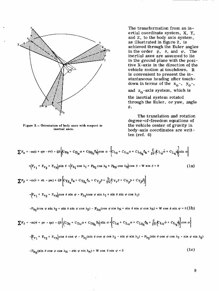
Figure 2.- Orientation of body axes with respect to inertial axes.
The transformation from an in- ertial coordinate system, X, Y, and Z , to the body axis system, as illustrated in figure 2, is achieved through the Euler angles in the order +, 8 , and 'p. The inertial axes are assumed to lie in the ground plane with the posi- tive X-axis in the direction of the vehicle motion at touchdown. It is convenient to present the in- stantaneous heading after touch- down in terms of the xo-, yo-, and zo-axis system, which is the inertial system rotated through the Euler, o r yaw, angle $.
The translation and rotation degree-of-freedom equations of the vehicle center of gravity in body-axis coordinates are writ - ten (ref. 6)
+pV1 + F,~ + FvN)sin e -(Fhl cos hl + Fh2 cos ~2 + a N c o s AN)COS e - w sin e = o (la)
-pVl + F , ~ + F , ~ ~ ) C O S e sin cp - Fhl(cos cp sin + sin e sin cp cos h i )
-Fh (cos cp sin AZ + sin e sin cp cos ~ 2 ) - FhN(cos cp sin AN + sin e sin cp cos AN) + w cos e sin cp = o (lb) 2
-FVl + F , ~ + F,~)COS e cos cp - Fh (sin e cos cp cos - sin cp sin hl) - Fh2(sin e cos cp cos ~2 - sin cp sin +) 1
-Fh (sin e COS cp cos AN - sin cp sin AN) + W cos e cos cp = 0 ( I C ) N
9

+F"~(RA cos cp + d l sin cos e - F , ~ ( R A ~ C O S cp - d2 sin
3
cos e + FvNdN cos e sin cp 1
+ F h l [ ~ l c o s cp + dl sin sin 0 cos A 1
-Fh2[(kA2 COS Cp - d2 sin .) sin 0 COS A2 -@A2 sin CP + d2 COS
cp - dl cos
+ h N d N ( cos cp sin AN + sin e sin cp cos AN) = o (Id)
+FVl(dl sin e - E l cos e cos cp) + Fv2(d2 sin e - 12 cos e cos cp) + FvN(dN sin e + 1~ cos e cos cp)
+Fhl 11 sin cp sin Al - (Il sin 8 cos cp + dl cos 0 ) cos A1 [ 1 [ 1
1 +Fh2 1, sin cp sin A2 - (12 sin 0 cos cp + d2 cos 0) cos A2
sin cp sin AN - ( I N sin e cos cp - dN cos e) COB AN = 0
+ F V 1 P 1 sin e + 1, cos 0 sin cp) - Fv2(RA2 sin 8 - 12 cos 0 sin cp - F v N l ~ cos 0 sin cp
+Fhl 1, cos cp sin A1 + ( I , sin 0 sin cp - R A ~ C O S e ) cos A1
)
[ I 1 I +Fh2 l2 cos cp sin A2 + (12 sin e sin cp + R A ~ cos e ) cos A2
(If) -fi 1 (cos cp sin AN + sin e sin cp cos AN) = 0 N N
where landing-gear contributions to the forces and moments are recognized as the terms involving the vertical forces on the gear Fv and the drag forces on the gear Fh. The aerodynamic coefficients included in equations (1) are those most commonly used for aircraft stability and control analyses; however, the importance of each derivative and the possible inclusion of others will depend on the vehicle configuration being con- s idered.
Landing -Ge a r Analysis
The deflection of the landing gear, such as gear bending and t ire deflection, con- stitutes additional degrees of freedom. The importance of these deflections on the
10

loads is dependent on the type of gear being considered. In addition to the deflections, it is necessary to consider equipment provided for energy absorption. Again, the type of gear limits generalization of the analysis; however, since most aircraft landing gear utilize oleopneumatic shock struts, this type of strut will be discussed.
Oleopneumatic shock struts do not begin to deflect during impact until sufficient force is developed to overcome the preload o r breakout force caused by the inflation pressure and by friction. Before this instant, the shock s t ru t is effectively rigid in compression and the gear load is a function of the gear structural o r tire deflection, or both, or
Fvi = F6i
As the vehicle descent continues, the preload is exceeded and the shock strut begins to displace. The gear vertical reactions become
where the airspring load FA is a function of the shock-strut displacement, and the hydraulic load FH is a function of both the displacement and the rate of displacement
of the shock strut. The friction load Ff is determined by the normal load on the
shock-strut-cylinder bearing surfaces and the coefficients of friction of the surfaces.
The overall rate of vertical deflection of the gear is related to the center-of- gravity vertical velocity by (ref. 6)
1 . . 6i = hi + io - [ZHi cos 9 + (di COS q + %sin q) sin 8 8, + (Ri COS cp - di sin q) 40 cos 0 (4)
where the dimension Z H ~ is positive for nose gear and negative for main gear; €$ is
positive for right main gear, negative for left main gear, and zero for nose gear; di is positive for all gear; and hi is the rate of change of vertical height of point of attachment due to rigid-body rotation about the point of gear contact. The equations are arranged so that a positive rate indicates shock-strut compression.
-
The analysis of the gear loads and associated gear and shock-strut deflections depends upon the structure and geometry of the gear as well as the characteristics of the shock struts. An example of a detailed analysis of a gear system equipped with oleopneumatic shock struts is given in appendix A.
11
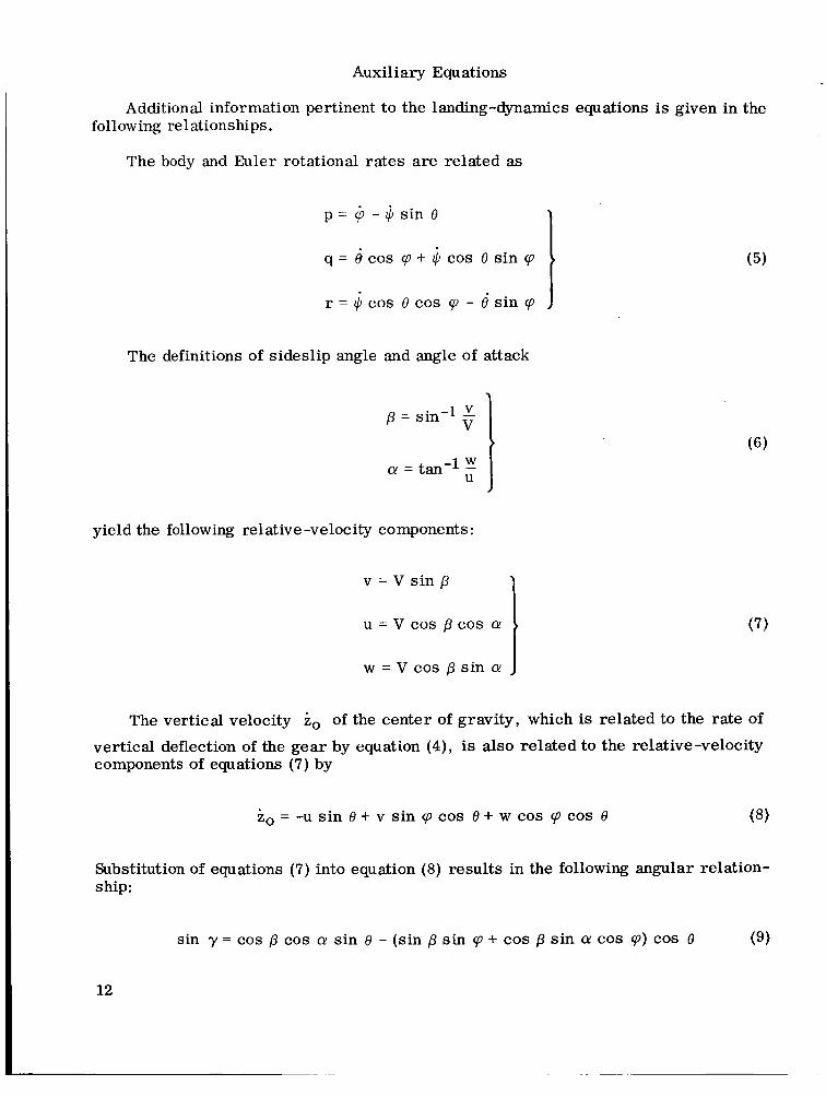
Auxiliary Equations
Additional information pertinent to the landing-dynamics equations is given in the following re1 ationships.
The body and Euler rotational rates are related as
p = + - q = 6 cos sp + li, cos e sin 9
r = cos e cos p - e'sin p
sin o
The definitions of sideslip angle and angle of attack
yield the following relative-velocity components:
v = V sin p
u = v cos p cos Q
w = V cos p sin a!
The vertical velocity io of the center of gravity, which is related to the rate of
vertical deflection of the gear by equation (4), is also related to the relative-velocity components of equations (7) by
io = -u sin e + v sin p cos e + w cos 9 cos e ( 8 )
Substitution of equations (7) into equation (8) results in the following angular relation- ship:
(5)
sin y = cos p cos Q sin e - (sin p sin p + cos p sin Q cos p) cos 8 (9)
12

where the flight-path angle y is defined by
The gear horizontal load at the ground-contact point is proportional to the gear reaction normal to the ground and is expressed as
The trigonometric relations for the friction force angles hi are given in refer- ence 6 as follows:
where
and
(v;~)~ = vii cos e + v ( f
(“;“)i = v;~ cos - VI sin q zi
Vii = u’+ qzi - ryi
VGi =v’+ mi - pzi
VLi = w’ + pyi - qxi
13

u/ = [V cos p - V, (cos +w cos + + sin qW sin +)] cos e
v/ = v sin p - vW[(sin +w cos + - cos +w sin + cos 9 ) + cos +w cos J I + sin qW sin + sin 0 sin 50 1 ( )
W K )
(15)
w/ = V cos p sin e - V cos qW cos + + sin zjW sin + sin 9 cos q
- (sin qW cos + - cos +w sin + sin q ) I Simplified Landing-Dynamics Equations for a Vehicle
With Tricycle Landing Gear
I The equations presented in the preceding section provide an analysis of the landing dynamics of a rigid flight vehicle which is unpowered during landing. A solution of these equations, while not impossible, becomes very complex and time consuming.
I However, it is possible to simplify the solution by making several assumptions.
One approximation is that the landing is made symmetrically; that is , both main gear impact simultaneously, the vehicle roll and yaw rates are zero, and the vehicle has no sideslip. In addition, i f there is no wind and if lateral control inputs are not made, that is ,
the symmetry of the landing will imply that
B
i
vw = 0
6, = 0
6, = 0
be maintained. These restraints on the vehicle motion
14

% The symmetry of the vehicle and the assumption of maintaining symmetrical landing conditions result in
Substitution of the auxiliary equations (5), (7), (8), and (11) into the equilibrium equations (1) and (4) yields, upon application of equations (16), (17), and (18), the following landing-dynamics equations fo r a vehicle with a tricycle landing gear:
ZF, = - m k cos Q + V + sin a + CD 6 cos a - C L ~ + C L , ~ + C ~ ~ ~ 6 h + 6h h, I
+(2FvM + FvN)sin e - ( 2 p ~ F , ~ + pNFVN) cos e - w sin e = 0 (19a)
c F y = 0 (19b)
- + c D , ~ + c D ~ ~ ~ ~ ) sin Q + p L o + cLQa + CLdhbh + & (cLb& + cL
9
- (2FvM + FvN) cos 0 - 2pMFvM + pNFvN) sin 0 + W cos 0 = 0 i (19c)
C%=O (19d)
15

Also
- iM = hM - v sin y+(zH cos e - dM sin e
M
It should be noted that the restraints expressed in equations (17) reduce auxiliary equation (9) to the familiar form of
Equations (19) along with equation (21) form a set of four equations for determining V, y , e, and a. Equation (3) for the gear loads is valid but remains dependent on the particular gear configuration. The motions of the vehicle and the gear system are related by equations (20).
Simplified Landing-Dynamics Equations for the X-15 Airplane
Landing experience with the X-15 airplane (fig. 3) revealed that once main-gear touchdown occurs, nose-gear impact follows in a short period of time (refs. 1 to 4).
E-7469 Figure 3.- X- 15 airplane during landing.
16

This fact allows two simplifying approximations to be made to the equations of the previous section. the landing phase, o r
. First, the velocity of the X-15 can be assumed to be constant during
V = constant + = 0
Second, the pitch attitude e and angle of attack a reduce to small angles very rapidly so that small-angle approximation may be used as
sin (e, a) = e, a
COS (e, a) = 1
Application of these approximations to equations (19) results in
Equations (22) along with equation (21) form a set of landing-dynamics equations for the parameters e, y, and a. Note that the equation for summation of forces in the x-direction, which provides information about drag forces on the airplane, has not been included.
Since the rate of change in vertical height due to rigid-gear rotation h is normally small compared to the gear-deflection rates, the overall gear vertical deflections (eqs. (20)) become
17

Also, because of the small-angle approximation
and the simplified equations for the landing dynamics of the X-15 become
Equations (24) with equation (21) form a complete set of equations for analyzing the landing dynamics of the X-15 airplane. A detailed presentation of the X-15 gear vertical reactions for determining equations (24d) is given in appendix A.
RESULTS AND DISCUSSION
The landing dynamics of a flight vehicle equipped with a tricycle oleopneumatic landing-gear system are presented in equations (1) to (4). This set of equations describes the dynamics of a rigid-body vehicle during landing impact, including
18

rolling, pitching, and yawing motions, variable aerodynamics and coefficients of friction, and the effects of pilot control inputs. These equations can be simplified to the form of equations (19) and (20) if the landing is made symmetrically. For the specific example of the X-15 airplane, the rapid pitch down at landing (refs. 1 to 4) allows a further simplification of the landing dynamics described by equations (24).
*
‘
The analysis was verified by comparing results of calculations for equations (24) with experimental results from the X-15 airplane. Initially, computations were made by using the gear-load curves shown in figure 4, which are based on analytical and ex- perimental data, rather than the procedure outlined in appendix A. The total vertical- load curve presents the ratio of vertical load to the design vertical load at the main- gear skid as a function of the ratio of vertical deflection to the maximum vertical de- flection of the gear. Velocity-sensitive curves for an arbitrary range of sink speed Vv
are shown. The orifice opens at approximately the same deflection for each sink speed,
1.2
1.0
.8
FV - FVD ’
main-gear- .6 skid vertical-
load ratio
.4
.2
0
/ / Hydraulic load
I I I I I I t I I I .1 . 2 . 3 .4 .5 .6 .7 .8 .9 1.0
main-gear-skid vertical-travel rat io K X ’
Figure 4.- Approximate variation of X- 15 main-gear-skid load with skid vertical travel and sink speed derived from analytical and experimental data.
= 1.0. It resulting in the single curve to the maximum deflection; that is ,
should be noted that once orificing occurs the load is independent of sink speed and
6M
o m a x relatively independent of deflection until large deflections-occur. As maximum de- flection of the shock strut is approached, the airspring load becomes predominant, since the hydraulic load is negligible as a result of decreased strut velocity.
19

Flight-test results and computations based on the total vertical-load curve of figure 4 were compared in reference 2. The comparison is reproduced in this paper as figure 5. It is apparent that the calculated vertical skid load agrees well with the flight-test results. The simplified analysis predicted the existence of a second re- action as well as the magnitude of the first and second reactions, thereby verifying the dynamic simulation of the landing dynamics.
r Fliqht test -- Calculated (using figure 4)
f " - FVD '
main -gear- skid vertical-
load ratio . 4
.2
0 .4 .6 .8 1 1.6
Time after main-gear touchdown, sec
Figure 5.- Comparison of X-15 main-gear-skid-load time histories (from ref. 2).
The simplified analysis based on figure 4 provided extensive information on the effects of various parameters such as gear position and sink speed (refs. 2 and 4). After an emergency landing of the X-15 airplane (ref. 4), the landing analysis was used to simulate the landing and to predict the results of severe off-design landing conditions. It was at this point that the deficiencies of the load curve of figure 4 were realized. Since the gear-load curve was obtained for conditions within the design envelope of the gear, attempts to use the curve for off-design conditions produced unrealistic results. Therefore, the landing-gear-dynamics equations of appendix A were incorporated into the analysis.
In order to provide confidence in the modified analysis, the experimental drop tests of the landing gear were simulated. The basic landmg equations were simplified as shown in appendix B. Drop-test and analytical results for the main gear and nose gear are compared in figures 6(a) and 6(b); the agreement is considered to be satis- factory.
20

FS 7
FsD main-gear
shock-strut- load ratio
FVN F'
VND nose-gear vertical- load ratio
1. I
.I
. t
.i
. L
C
1.0
.8
.6
. 4
Drop test -- Calculated (using appendixes A and 6)
I I I I 1 .2 .4 .6 . 8 1.0
6s 6):
(a) Main gear. -
Drop test -- Calculated (using appendixes /' - A and BI
-
\
0 . 2 . 4 .6 .8 1.0 6 N
( d N X n a X
(b) Nose gear.
Figure 6.- Comparison of calculated shock-strut load with drop-test data.
21

The results shown in figure 6 provide confidence in the analysis, but the proper simulation of the landing dynamics of the vehicle system is required as final proof of the validity of the analysis. Results from flight tests and the modified analysis are compared in figure 7. The good agreement obtained in predicting the magnitudes of the first and second reactions as well as a reasonable comparison of overall time
1.6
1 . 2
FS - FsD’
main-gear . E shock-strut-
load rat io
.4
F,N F ’
nose-gear vert ical- load rat io
VND
Flight test -- Calculated (using appendix A)
A /-
I / ’ \ Time after main-gear touchdown, sec
(a) Main gear.
Flight test -- Calculated (us ing appendix A)
.* t
Y I I I I I I 0 .04 .08 .12 .16 .20 .24
Time after nose-gear touchdown, sec
(b) Nose gear.
Figure 7.- Comparison of flight-test and calculated shock-strut time histories. QO - = 1.06; - - vvo - 0.20; - WO = 0.99. QD v V D WD
22

history for the main gear (fig. ?(a)) indicates that the modified analysis yields accept-
although the magnitude of the peak reaction is predicted satisfactorily, the nose-gear dynamics are not simulated precisely. The discrepancies in the simulation are attrib- uted to the neglect of nose-gear-tire spin-up loads and strut-bending characteristics. Similar comments are applicable to most main landing gear. For the X-15 main gear, however, metal skids are used in place of wheels and tires and no bending moments are applied to the shock strut, since drag loads are absorbed by drag links attached at the skids and vertical loads are applied to the shock strut through a bell- crank (see ref. 1 for description of the X-15 landing-gear system).
a valuable tool for assessing operational problems or studying the effects of unusual configurations as well as for evaluating design concepts. Equally important for research vehicles, such as the X-15, is the capability of investigating off-design o r emergency landing conditions for which it is unrealistic to obtain flight-test data. The analysis can be used to determine the severity of the contingencies and to devise pos- sible emergency procedures for minimizing the landing loads. As an example, main- gear loads are shown for the X-15 in figure 8 for a flap malfunction and excessive
. able results. The nose-gear time histories, compared in figure 7(b), reveal that,
.
The capability of analytically simulating the landing dynamics of a vehicle provides
2.0
1.6
1.2
FV - Fvg’
main-gear- skid vertical-
load ratio .8
. 4
n I I I I I I
Figure 8.- Influence of airplane landing weight and flap position on maximum main-gear load calculated by using a0
method of appendix A. !!Q = 0.55; -= 1.0; an = lg. vVD a D
23

landing weights. The normal landing condition, in which flaps are used, is presented for comparison. For both the flaps -up and flaps -down curves, the horizontal-tail position is maintained at the pre-touchdown tr im position 6 nahtre of landing without the use of flaps is evident, particularly if the design weight is exceeded; however, the effect of excessive weight during a flaps-down landing is small and is of less importance than a flap malfunction. The normally detrimental effects of aerodynamic loads and weight on X-15 landing loads, which are discussed in refer- ences 3 and 4, are thus seen to be particularly severe during an emergency landing.
. The critical %rim
It is of interest to illustrate, through the use of analysis, how the aerodynamics can be used advantageously to alleviate the landing loads during emergency conditions. X-15 main-gear landing loads are presented in figure 9 as a function of weight for the severe emergency of a flap malfunction. The horizontal-tail loads are manipu- lated during the landing to achieve the three curves shown. which was shown in figure 8, offers only limited capabilities for the emergency landing, and the normal pilot technique of pulling back on the control stick 6hPu11 is intolerable.
maneuver, The %rim
However, the push maneuver h ’ discussed in references 3 and-4, in which the
W - WD
Figure 9.- Influence of horizontal-tail position on maximum main-gear load calculated by using method of vv a0 appendix A. - = 0.55; - = 1.0; an = Ig; flaps up. vVD QD
24

pilot pushes forward on the control stick at touchdown results in main-gear loads that are lower o r only slightly higher than the gear design load even for severe off-design landing conditions of excessive weight and a flap malfunction. It should be pointed out that the ineffectiveness of the horizontal tail in controlling nose-gear loads, because of the location of the tail, results in only a slight increase in nose-gear load because of the push maneuver (refs. 3 and 4).
'
Experience with the X-15 airplane has revealed that the aerodynamic loads are extremely important to the landing dynamics because of the unusual relative location of landing gear and aerodynamic surfaces of the vehicle. Results from the analysis, such as those in figure 9, have further shown that by proper manipulation of the horizontal- tail aerodynamic loads the initially detrimental effects on landing loads can be used advantageously to expand the X-15 landing envelope to include high landing weights and no-flap emergencies.
CONCLUDING REMARKS
A theoretical analysis has been presented for the landing dynamics of a vehicle with a tricycle landing-gear system. The equations were reduced by simplifying assumptions which resulted in a modified analysis consistent with the landing dynamics of the X-15 airplane. Calculations were made with the modified analysis in order to compare the theoretical landing loads with flight- and drop-test data. Comparison of calculated results with flight-test data indicates that the modified analysis adequately simulates the landing dynamics of the X-15 airplane as well as predicts the magnitudes of the peak loads.
Parameter studies conducted for the X-15 illustrated the effects of weight, flap position, and horizontal-tail position on the main-gear loads. The results of this analysis indicate that it is possible to advantageously use the unusual relationship between the aerodynamics and the landing-gear configuration to expand the landing envelope to include higher weights and no-flap emergencies.
Flight Research Center, National Aeronautics and Space Administration,
Edwards, Calif., May 1, 1967, 7 19 -0 1-00 -04 -24.
25

APPENDIX A
ANALYSIS O F VERTICAL LOADS ON THE X-15 LANDING GEAR
Main Gear
The X-15 main landing gear is of the articulated type, as illustrated in the sketch below. (See reference 1 for a detailed discussion. )
t FV
The ground reaction Fv is transmitted through a skid, landing-gear-leg, and
bell-crank arrangement to an oleopneumatic shock strut inside the fuselage. shock-strut displacement, the vertical load is a function of the vertical skid displacement due to leg bending. The bending load can be expressed as
Prior to
where K is the stiffness coefficient of the main-gear leg which relates vertical load to vertical deflection. This coefficient can be described analytically but is obtained more practically by static tests.
overall gear deflection described by equation (4) or equations (20) o r ( 2 4 ~ ) .
The vertical-bending deflection 6~ is equivalent to the
After shock-strut motion, the vertical load is expressed a s in equation (3). Be- cause of the articulated nature of the main gear, the vertical load at the ground and the shock-strut load are not equivalent; however, they can be related through the gear geometry. Equating moments about the gear pivot (see preceding sketch) results in
B A s F v = - F
26

APPENDIX A
B
rotates about the pivot, and of the shock-strut load Fs. The load Fs is given by
The gear vertical load is a function of the ratio A, which varies as the gear
where the quantities are defined as for equation (3). For the X-15 airplane, the friction forces Ffs are assumed to be negligible. The shock-strut airspring load FA^ is determined experimentally for the X-15 but can be obtained analytically (see ref. 7). The hydraulic load F H ~ is related to the shock-strut velocity ds by
where Cs is an experimentally defined hydraulic coefficient. The load does not have a direction sign as in reference 7 , since the X-15 shock strut produces hydraulic load only in compression. During the expansion stroke, hydraulic pressure is relieved through orifices so that the load is the result of the airspring only. This condition is approximated by
The vertical and shock-strut loads were related by equation (A2). Using the same technique
where 6~ is the rate of vertical deflection of the main gear due to the rigid rotation R of the gear about the pivot.
Substituting equations (A3), (A4),
Fv =
and (A6) into equation (A2) results in
F * + C d 2 MR
where
27

APPENDIX A
The X-15 main-gear shock strut also incorporates a pressure-relief valve which, upon opening, prevents a further increase in hydraulic pressure. Until the valve opens, the strut is velocity-sensitive, but after the orificing the strut load is the air- spring load with the pressure-limited non-velocity-sensitive hydraulic load added to it. Therefore, as long as the relief valve is open, equation (A4) becomes
- -
where (E"s) is the maximum attainable hydraulic load. max
The skid load of equation (A?) is then written
where @Ismax = A Hs )
The overall vertical-deflection rate 6, given by equation (4) o r by equations (20)
o r (24c) is the sum of the rates of vertical deflection o r
The rate of bending deflection is now obtained by considering the main-gear leg as a single-degree-of-freedom damped spring mass. Then
where g is the gravitational acceleration, C1 is the damping coefficient, and mM is the mass of the main-gear leg.
Nose Gear
The X-15 nose gear is a conventional-type gear (ref. l), utilizing dual co- rotating wheels and t ires and an oleopneumatic shock strut. The vertical load F, prior to shock-strut displacement is a function of the tire deflection 6, or
28

APPENDIX A
I where obtained experimentally for the X-15. The tire deflection is equivalent to the overall nose-gear deflection given by equation (4) o r equations (20) or (24c).
Ft is the vertical load on the tire. The relationship between F, and 6, is
. After shock-strut motion, the vertical load is described by equation (3). Since
gear bending has been neglected, the methods of reference 7 result in
6 Fv = FA + CNbS2 4
1% I
where the airspring load FA and the hydraulic coefficient CN are experimentally
determined functions of the nose-gear shock-strut deflection 6,.
The shock-strut deflection is related to the overall gear-deflection rate by
The rate of the tire deflection is obtained by considering the wheel and tire as a single -degree+of-freedom damped spring mass. Then
.. Fv - Ft 6, = g +
"N
where mN is the mass of the tire and wheel.
29

APPENDIX B
RELATIONS FOR DROP-TEST SIMULATION
Drop tests of the X-15 landing gear were made to determine the actual gear characteristics. Each gear was tested individually rather than as a complete landing- gear system. Weight was added to the basic landing gear to simulate inertia loads due to vertical motion. Thus, equation (24a) for vertical motion becomes for each gear
mZo = W - L - Fv (B1)
where L represents a simulated aerodynamic force. Equations (24c) are then re- placed by
0 .
6 = zo
where initially io = Vv.
The equations of appendix A are still applicable for the gear-drop tests. The mass m and weight W are the effective masses and weights computed for the critical landing conditions.
30

. REFERENCES
1. McKay, James M. ; and Scott, Betty J. : Landing-Gear Behavior lXlring Touchdown and Runout for 17 Landings of the X-15 Research Airplane. NASA TM X-518, 1961.
2. McKay, James M. ; and Kordes, Eldon E. : Landing Loads and Dynamics of the X-15 Airplane. NASA TM X-639, 1962.
3. Noll, Richard B. ; Jarvis, Calvin R. ; Pembo, Chris; Lock, Wilton P. ; and Scott, Betty J. : Aerodynamic and Control-System Contributions to the X-15 Airplane Landing-Gear Loads. NASA TN D-2090, 1963.
4. McKay, James M. ; and Noll, Richard B. : A Summary of the X-15 Landing Loads. NASA TN D-3263, 1966.
5. Mechtly, E. A. : The International System of Units - Physical Constants and Conversion Factors. NASA SP-7012, 1964.
6. Noll, Richard B. ; and Halasey, Robert L. : Theoretical Investigation of the Slideout Dynamics of a Vehicle Equipped With a Tricycle Skid-Type Landing-Gear System. NASA TN D-1828, 1963.
7. Milwitzky, Benjamin; and Cook, Francis E. : Analysis of Landing-Gear Behavior. NACA Rep. 1154, 1953.
NASA-Langley, 1967 - 2 H-477 31

, dJ \ “The aeronautical and space activities of the United States shall be
conducted so a.r to contribute . . . to the expansion of human knowl- edge of phenomena in the atmosphere and space. The Administration shall provide for the widest practicable and appropriate dissemination of information concerning its activities and the results tbereof.”
-NATIONAL AERONAUTICS AND SPACE ACT OF 1958
NASA SCIENTIFIC AND TECHNICAL PUBLICATIONS
TECHNICAL REPORTS: Scientific and technical information considered important, complete, and a lasting contribution to existing knowledge.
TECHNICAL NOTES: Information less broad in scope but nevertheless of importance as a contribution to existing knowledge.
TECHNICAL MEMORANDUMS: Information receiving limited distribu- tion because of preliminary data, security classilication, or other reasons.
CONTRACTOR REPORTS: Scientific and technical information generated under a NASA contract or grant and considered an important contribution to existing knowledge.
TECHNICAL. TRANSLATIONS: Information published in a foreign language considered to merit NASA distribution in English.
SPECIAL PUBLICATIONS: Information derived from or of value to NASA activities. Publications include conference proceedings, monographs, data compilations, handbooks, sourcehks, and special bibliographies.
TECHNOLOGY UTIllzATION PUBLICATIONS: Information on tech- nology used by NASA that may be of particular interest in commercial and other non-aerospace applications. Publications include Tech Briefs, Technology Utilization Reports and Notes, and Technology Surveys.
Details on the availability of these publications may be obtained from:
SCIENTIFIC AND TECHNICAL INFORMATION DIVISION
NATIONAL AERONAUTICS AND SPACE ADMINISTRATION
Washington, D.C. PO546