theoretical bounds on data requirements for the ray …
TRANSCRIPT
THEORETICAL BOUNDS ON DATA REQUIREMENTS FOR THE
RAY-BASED CLASSIFICATION
BRIAN J WEBER
Institute of Mathematical SciencesShanghaiTech University, Shanghai, 201210, China
SANDESH S KALANTRE
Joint Quantum Institute, University of Maryland
College Park, MD 20742, USA
THOMAS MCJUNKIN
Department of Physics, University of Wisconsin
Madison, WI 53706, USA
JACOB M TAYLOR
National Institute of Standards and TechnologyGaithersburg, MD 20899, USA
JUSTYNA P ZWOLAK
National Institute of Standards and TechnologyGaithersburg, MD 20899, USA
The problem of classifying high-dimensional shapes in real-world data grows in complex-
ity as the dimension of the space increases. For the case of identifying convex shapesof different geometries, a new classification framework has recently been proposed in
which the intersections of a set of one-dimensional representations, called rays, with theboundaries of the shape are used to identify the specific geometry. This ray-based classi-fication (RBC) has been empirically verified using a synthetic dataset of two- and three-dimensional shapes [1] and, more recently, has also been validated experimentally [2].
Here, we establish a bound on the number of rays necessary for shape classification,defined by key angular metrics, for arbitrary convex shapes. For two dimensions, we de-
rive a lower bound on the number of rays in terms of the shape’s length, diameter, andexterior angles. For convex polytopes in RN , we generalize this result to a similar boundgiven as a function of the dihedral angle and the geometrical parameters of polygonalfaces. This result enables a different approach for estimating high-dimensional shapes
using substantially fewer data elements than volumetric or surface-based approaches.
Keywords: Deep Learning; Image Classification.
Mathematics Subject Classification 2020: 68T20, 68Q32, 68U10
1
arX
iv:2
103.
0957
7v1
[cs
.LG
] 1
7 M
ar 2
021

2 B. J. Weber, S. S. Kalantre, T. McJunkin, J. M. Taylor, J. P. Zwolak
1. Introduction
The problem of recognizing objects within images has received immense and grow-
ing attention in the literature. Aside from visual object recognition in two and three
dimensions in real-world applications, such as in medical images segmentation or
in self-driving cars, recognizing and classifying objects in N dimensions can be im-
portant in scientific applications. A problem arises in cases where data is costly
to procure; another problem arises in higher dimensions, where shapes rapidly be-
come more varied and complicated and classical algorithms for object identification
quickly become difficult to produce. We combine machine learning algorithms with
sparse data collection techniques to help overcome both problems.
The method we explore here is the ray-based classification (RBC) framework,
which utilizes information about large N -dimensional data sets encoded in a col-
lection of one-dimensional objects, called rays. Ultimately, we wish to explore the
theoretical limits of how little data—how few rays, in our case—is required for re-
solving features of various sizes and levels of detail. In this paper, we determine
these limits when the objects to be classified are convex polytopes.
The RBC framework measures convex polytopes by choosing a so-called obser-
vation point within the polytope, shooting a number of rays as evenly spaced as
possible from this point, and recording the distance it takes for each ray to encounter
a face. While it is reasonable to expect that an explicit algorithm for recognizing
polygons in a plane can be developed, in arbitrary dimension such an explicit algo-
rithm would be tedious to produce and theoretically unelightening. Since our work
presumes a high cost of data acquisition but not computing power, we leave the
actual classification to a machine learning algorithm. This paper produces theoret-
ical bounds on how little data is required for a neural network to reliably classify
shapes.
This project originated in the context of quantum information systems, specifi-
cally in the problem of calibrating the state of semiconductor quantum dots to work
as qubits. The various device configurations create an irregular polytopal tiling of
a configuration space, and the specific shape of a polytope conveys useful infor-
mation about the corresponding device state. Our goal is to map out these shapes
as cost-effectively as possible. Here, the cost arises because polytope edges are de-
tected through electron tunneling events which places hard physical limits on data
acquisition rates. Apart from this original application, the techniques we developed
should be valuable in any situation where object classification must be done despite
constraints on data acquisition.
2. Related Work
In the broad field of data classification in N = 2, 3, 4, etc. dimensions, there are
many unique approaches, often tailored to the constraints of the problem at hand.
For example, higher dimensional data can be projected onto lower dimensions to
employ standard deep learning techniques such as 3D ConvNets [3–5]. Multiple low
Theoretical data bounds for ray-based classification 3
dimensional views of higher dimensional data can be collected to ease data collection
and recognition [6]. Models such as ShapeNets [7] directly work with 3D voxel
data. Data collected using depth sensors can be presented as RGB-D data [8–10]
or point clouds [11, 12] representing the topology of features present. Often, depth
information is sparsely collected due to limitations of the depth sensors themselves.
Within the field of representing 3D or higher dimensional data as point clouds,
data can be treated in various ways such as simply N -dimensional coordinates in
space [13], patches [14], meshed polygons [15], or summed distances of the data
to evenly spaced central points [16]. Critically, the RBC approach is suited for an
environment in which data can be collected in any vector direction in N dimensional
space while even coarse data collection of the total space would be practically too
expensive or unfeasible.
Historically, it is well-known that the complexity of any classification problem
intensifies in higher dimensions. This is the so-called curse of dimensionality [17],
which has a negative impact on generalizing good performance of algorithms into
higher dimensions. In general, with each feature and dimension, the minimum data
requirement increases exponentially. This can be seen in the present work: according
to Theorem 4.2, the data requirement increases like√NeαN . At the same time, in
many applications data acquisition is very expensive, resulting in datasets with a
large number of features and a relatively small number of samples per feature (so-
called High Dimension Low Sample Size datasets [18]). To address these problems,
a number of algorithms have been proposed to effectively select the most important
features in the dataset (see, e.g., [19–23]).
3. Problem Formulation
We begin with a convex regionQ ⊆ RN along with a point xo, the observation point,
in the interior of Q. Given a unit vector v, the ray based at xo in the direction v is
Rxo,v = {xo + tv | t ∈ [0,∞)}. (3.1)
The set of directions v at xo is naturally parameterized by the unit sphere SN−1.
M many directions v1, . . . , vM ∈ SN−1 produces M many rays {Ri}Mi=1, Ri =
Rxo,vi based at xo. Because Q is convex, in the direction vi there will be a unique
distance ti at which the boundary ∂Q is encountered. Given a set of directions and
an observation point, the corresponding collection of distances is called the point
fingerprint.
Definition 3.1. Given a convex region Q, a point xo ∈ Q, and a set of directions
{vi}Mi=1 ⊂ SN−1, the corresponding point fingerprint is the vector
F(Q, xo, {vi}Mi=1) ≡ Fxo=(t1, . . . , tM
)(3.2)
where ti ∈ (0,∞] is unique value with xo + tivi ∈ ∂Q.
In practice, there will be an upper bound on what values the ti may take, which
we call T . If the ray does not intersect ∂Q prior to distance T , one would record

4 B. J. Weber, S. S. Kalantre, T. McJunkin, J. M. Taylor, J. P. Zwolak
ti = ∞, indicating the region’s boundary is effectively infinitely far away in that
direction.
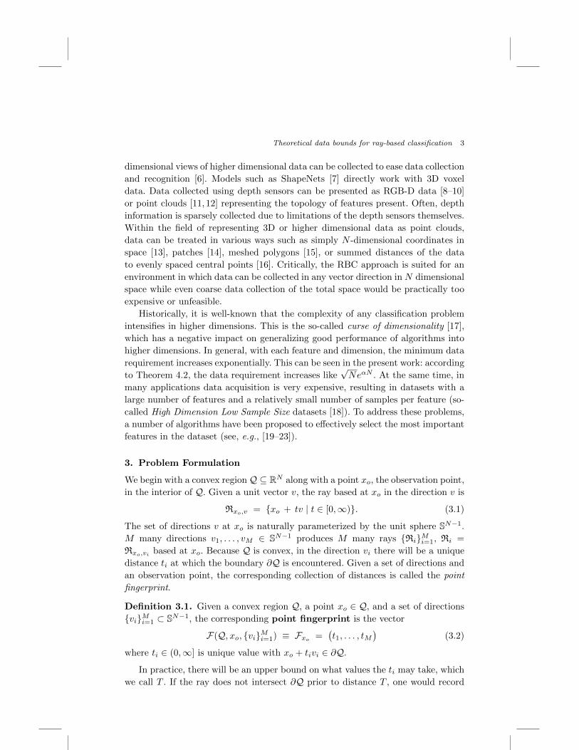
The fingerprinting process is depicted in Fig. 1(a). The question is to what extent
one can characterize, or approximately characterize, convex shapes knowing only a
fingerprint. If nothing at all is known about the region Q except that it is convex,
full recognition requires infinitely many rays measured in all possible directions,
effectively resulting in measuring the entire N -dimensional space. However, it turns
out that if one puts restrictions on what the objects could be—for instance if it is
known that Q must be a certain kind of polytope—information captured with a
fingerprint may be sufficient. Better yet, if we do not require a full reconstruction
of the shape but only some coarser form of identification, for example if we must
distinguish triangles from hexagons but do not care exactly what the triangles or
hexagons look like, then we can do with even smaller fingerprints.
With an eye toward eventually approximating arbitrary regions with polytopes,
we define the following polytope classes.
Definition 3.2. Given N ∈ {2, 3, . . .} and d, l, α > 0, let Q(N, d, l, α) be the class
of convex polytopes in RN that have diameter at most d, all face inscription sizes
at least l, and all exterior dihedral angles at most α.
The “inscription size” of a polytope face is the diameter of the largest possible
(N − 1)-disk inscribed in that face. In the case N = 2, polytopes are just polygons
and polytope faces are line segments. In this case the inscription size of a face is
just its length. For the case of N = 3, the inscription size of a face is the diameter of
the largest possible disk inscribed in this face, see Fig. 1(b). We can now formulate
the following identification problem.
Problem 3.1 (The identification problem). Given a polytope Q ∈Q(N, d, l, α), determine the smallest M so that, no matter where xo ∈ Q is placed,
a fingerprint made from no more than M many rays is sufficient to completely
characterize Q.
xo<latexit sha1_base64="8/cBf8ioppkQ2Gw76cUaufz52fE=">AAAB6nicbVDJSgNBEK2JW4xb1KOXxiB4CjMu6DHoxWNEs0AyhJ5OT9Kkl6G7RwxDPsGLB0W8+kXe/Bs7yRw0+qDg8V4VVfWihDNjff/LKywtr6yuFddLG5tb2zvl3b2mUakmtEEUV7odYUM5k7RhmeW0nWiKRcRpKxpdT/3WA9WGKXlvxwkNBR5IFjOCrZPuHnuqV674VX8G9JcEOalAjnqv/NntK5IKKi3h2JhO4Cc2zLC2jHA6KXVTQxNMRnhAO45KLKgJs9mpE3TklD6KlXYlLZqpPycyLIwZi8h1CmyHZtGbiv95ndTGl2HGZJJaKsl8UZxyZBWa/o36TFNi+dgRTDRztyIyxBoT69IpuRCCxZf/kuZJNTitnt+eVWpXeRxFOIBDOIYALqAGN1CHBhAYwBO8wKvHvWfvzXuftxa8fGYffsH7+AZr7I3l</latexit>
(a) (b)
↵<latexit sha1_base64="5uI7OHd2r47MUtx08AblU4N6pQU=">AAAB7XicbVDLSgNBEOyNrxhfUY9eBoPgKez6QI9BLx4jmAckS+idzCZjZneWmVkhLPkHLx4U8er/ePNvnCR70MSChqKqm+6uIBFcG9f9dgorq2vrG8XN0tb2zu5eef+gqWWqKGtQKaRqB6iZ4DFrGG4EayeKYRQI1gpGt1O/9cSU5jJ+MOOE+REOYh5yisZKzS6KZIi9csWtujOQZeLlpAI56r3yV7cvaRqx2FCBWnc8NzF+hspwKtik1E01S5COcMA6lsYYMe1ns2sn5MQqfRJKZSs2ZKb+nsgw0nocBbYzQjPUi95U/M/rpCa89jMeJ6lhMZ0vClNBjCTT10mfK0aNGFuCVHF7K6FDVEiNDahkQ/AWX14mzbOqd169vL+o1G7yOIpwBMdwCh5cQQ3uoA4NoPAIz/AKb450Xpx352PeWnDymUP4A+fzB43Fjx8=</latexit>
d<latexit sha1_base64="CC9FAILUx/kKnY89h2uonwUkgiY=">AAAB6HicbVDLSgNBEOz1GeMr6tHLYBA8hV0f6DHoxWMC5gHJEmZne5Mxs7PLzKwQQr7AiwdFvPpJ3vwbJ8keNLGgoajqprsrSAXXxnW/nZXVtfWNzcJWcXtnd2+/dHDY1EmmGDZYIhLVDqhGwSU2DDcC26lCGgcCW8Hwbuq3nlBpnsgHM0rRj2lf8ogzaqxUD3ulsltxZyDLxMtJGXLUeqWvbpiwLEZpmKBadzw3Nf6YKsOZwEmxm2lMKRvSPnYslTRG7Y9nh07IqVVCEiXKljRkpv6eGNNY61Ec2M6YmoFe9Kbif14nM9GNP+YyzQxKNl8UZYKYhEy/JiFXyIwYWUKZ4vZWwgZUUWZsNkUbgrf48jJpnle8i8pV/bJcvc3jKMAxnMAZeHANVbiHGjSAAcIzvMKb8+i8OO/Ox7x1xclnjuAPnM8fyi2M7w==</latexit>
l<latexit sha1_base64="Pt/KY6Z5IA6ecWeZ4NbArkd9egQ=">AAAB6HicbVDLSgNBEOz1GeMr6tHLYBA8hV0f6DHoxWMC5gHJEmYnvcmY2dllZlYIS77AiwdFvPpJ3vwbJ8keNLGgoajqprsrSATXxnW/nZXVtfWNzcJWcXtnd2+/dHDY1HGqGDZYLGLVDqhGwSU2DDcC24lCGgUCW8Hobuq3nlBpHssHM07Qj+hA8pAzaqxUF71S2a24M5Bl4uWkDDlqvdJXtx+zNEJpmKBadzw3MX5GleFM4KTYTTUmlI3oADuWShqh9rPZoRNyapU+CWNlSxoyU39PZDTSehwFtjOiZqgXvan4n9dJTXjjZ1wmqUHJ5ovCVBATk+nXpM8VMiPGllCmuL2VsCFVlBmbTdGG4C2+vEya5xXvonJVvyxXb/M4CnAMJ3AGHlxDFe6hBg1ggPAMr/DmPDovzrvzMW9dcfKZI/gD5/MH1k2M9w==</latexit>
<latexit sha1_base64="jcAO7z5eFy9RHzKKmJ6VrYQtlEo=">AAAB+nicbVA9TwJBEJ3DL8Qv1NJmIzGxIndGoyXRxhKjIAlcyN6yBxt27y67cybk5CfYam9nbP0ztv4SF7hCwJdM8vLeTGbmBYkUBl332ymsrK6tbxQ3S1vbO7t75f2DpolTzXiDxTLWrYAaLkXEGyhQ8laiOVWB5I/B8GbiPz5xbUQcPeAo4b6i/UiEglG00j12VbdccavuFGSZeDmpQI56t/zT6cUsVTxCJqkxbc9N0M+oRsEkH5c6qeEJZUPa521LI6q48bPpqWNyYpUeCWNtK0IyVf9OZFQZM1KB7VQUB2bRm4j/ee0Uwys/E1GSIo/YbFGYSoIxmfxNekJzhnJkCWVa2FsJG1BNGdp05rYEalyyoXiLESyT5lnVu6i6d+eV2nUeTxGO4BhOwYNLqMEt1KEBDPrwAq/w5jw7786H8zlrLTj5zCHMwfn6BZzGlII=</latexit>
tm
Fig. 1. (a) A sample polygon with 7 evenly spaced rays based at xo, with tm denoting the distance
from xo to the polygon edge ∂Q. (b) A depiction of a minimum interior diameter of a face l, theminimum exterior dihedral angle α, and the maximum possible polytope diameter d for a samplepolytope in R3.

Theoretical data bounds for ray-based classification 5
Again, the actual identification is done with a machine learning algorithm. Re-
solving Problem 3.1 will tell us how little data we can feed a neural network and
still expect it to return a good identification. In R2, we actually solve this problem
and find an optimal value of M . In higher dimensions we find a value for M that
works, but could be sharpened in some applications.
Hidden in Problem 3.1 is another problem we call the ray placement problem.
To explain this, note that a large number of rays may be placed at xo, but if the
rays are clustered in some poor fashion, very little information about the polytope
overall geometry will be contained in the fingerprint. This means that before one
can determine how many rays are needed, one must already know where to place
the rays.
In R2, this placement problem is easily solved: choosing a desired offset v0, the viare placed at intervals of 2π/M along the unit circle. In higher dimensions the place-
ment problem is much more difficult and we have to work with suboptimally-spaced
rays. In fact, as we discuss later in this paper, even in R3 an optimal placement is
out of reach. To overcome this problem, we propose a general placement algorithm
that works in arbitrary dimension and is reasonably sharp. As we show, the pro-
posed algorithm is sufficient to enable concrete estimates on the numbers of rays
required to resolve elements in Q(N, d, l, α).
In many practical applications, such as calibration of quantum dot devices men-
tioned earlier, Problem 3.1 is much too strict. Often we do not need to reconstruct
polytopes exactly but only classify them to within approximate specifications. For
example, we may only wish to know if a triangle is “approximately” a right trian-
gle, without needing enough data to fully reconstruct it. Or we may wish to distin-
guish triangles and hexagons, and not care about other polyhedra. Theoretically,
this involves separating the full polytope set Q(N, d, l, α) into disjoint subclasses
C1, . . . , CK ⊂ Q(N, d, l, α), with possibly a “leftover” set CL = Q(N, d, l, α)\⋃Ki=1 Ci
of unclassifiable or perhaps unimportant objects. The idea is that an object’s impor-
tance might not lie in its exact specifications, but in some characteristic it possesses.
Problem 3.2 (The classification problem). Assume Q(N, d, l, α) has been par-
titioned into classes {Ci}Ki=1. Given a polytope Q, identify the Ci for which Q ∈ Ci.
The classification problem is eminently more suitable for machine learning than
the full identification problem. This is in part because the outputs are more discrete
(we can arrange it so the algorithm returns the integer i when Q ∈ Ci), and in
part because machine learning usually produces systems good at identifying whole
classes of examples that share common features, while ignoring unimportant details.
Importantly, a satisfactory treatment of the classification problem can lead to
solutions of more complicated problems, such as classifying compound items like
tables, chairs, etc. in a 3D environment or geometrical objects obtained through
measurements of an experimental variable in some parameter space. Depending on
the origin or purpose of such objects, they naturally belong to different categories.
For example, in the 3D real world, furniture and plants define two distinct classes

6 B. J. Weber, S. S. Kalantre, T. McJunkin, J. M. Taylor, J. P. Zwolak
that, if needed, can be further subdivided (e.g., a subclass of chairs, tables). Objects
belonging to a single class, in principle, share common characteristics or similar
geometric features of some kind.
We close this section with two remarks. The first is that the RBC framework has
already seen considerable experimental success [1]. The second remark concerns a
subordinate problem that is beyond the scope of this work: boundary identification.
In the quantum computing application for which RBC was originally designed [1]
boundaries are identified by measuring discrete tunneling events, and there is little
ambiguity in determining when a boundary was crossed. Since the fingerprinting
method relies on identifying boundary crossings, in other circumstances boundary
detection might require some other resolution. For now we only mention that ma-
chine learning methods should be able to compensate, to an extent, for boundaries
that are indistinct or partially undetectable, as such algorithms often remain robust
in the presence of noise. We shall have more to say about this in future work.
4. Main Results
A solution to Problem 3.2 in the supervised learning setting is obtained by training
a deep neural network (DNN) with the input being the point fingerprint and an
output identifying an appropriate class. Apriori it is unclear how many rays are nec-
essary for a fingerprint-based procedure to reliably differentiate between polytopes.
With data acquisition efficiency being the focus of this work, we want to theoret-
ically determine the lower bound on the number of rays needed. Such a bound is
fully within reach for polygons in R2 (Theorem 4.1), and can be approximated in
all higher dimensions (Theorem 4.2).
For a polytope face to be visible in a fingerprint, at least one ray must intersect
it. To establish not only the presence of a face but its orientation in N -space, at
least N many rays must intersect it. The smaller a face is, the further away from
the observation point xo it is, or the more highly skewed its orientation is, the more
difficult it is for a ray to intersect it. We address the case of polygons in R2 first,
as we obtain the most complete information there.
4.1. The identification problem in R2
Recall that Q(2, d, l, α) is the class of polygons in the plane with diameter < d, all
edge lengths > l, and all exterior angles < α.
Theorem 4.1 (Polygon identification in R2). Assume Q is a polygon in
Q(2, d, l, α), and let xo be a point in the polygon’s interior, from which M many
evenly spaced rays emanate. If
M >
⌈4π
arcsin(ld sinα
)⌉, (4.1)
then two or more rays will intersect each boundary segment of Q, and one segment
will be hit at least 3 times.

Theoretical data bounds for ray-based classification 7
(b)(a)
d<latexit sha1_base64="CC9FAILUx/kKnY89h2uonwUkgiY=">AAAB6HicbVDLSgNBEOz1GeMr6tHLYBA8hV0f6DHoxWMC5gHJEmZne5Mxs7PLzKwQQr7AiwdFvPpJ3vwbJ8keNLGgoajqprsrSAXXxnW/nZXVtfWNzcJWcXtnd2+/dHDY1EmmGDZYIhLVDqhGwSU2DDcC26lCGgcCW8Hwbuq3nlBpnsgHM0rRj2lf8ogzaqxUD3ulsltxZyDLxMtJGXLUeqWvbpiwLEZpmKBadzw3Nf6YKsOZwEmxm2lMKRvSPnYslTRG7Y9nh07IqVVCEiXKljRkpv6eGNNY61Ec2M6YmoFe9Kbif14nM9GNP+YyzQxKNl8UZYKYhEy/JiFXyIwYWUKZ4vZWwgZUUWZsNkUbgrf48jJpnle8i8pV/bJcvc3jKMAxnMAZeHANVbiHGjSAAcIzvMKb8+i8OO/Ox7x1xclnjuAPnM8fyi2M7w==</latexit>
↵<latexit sha1_base64="5uI7OHd2r47MUtx08AblU4N6pQU=">AAAB7XicbVDLSgNBEOyNrxhfUY9eBoPgKez6QI9BLx4jmAckS+idzCZjZneWmVkhLPkHLx4U8er/ePNvnCR70MSChqKqm+6uIBFcG9f9dgorq2vrG8XN0tb2zu5eef+gqWWqKGtQKaRqB6iZ4DFrGG4EayeKYRQI1gpGt1O/9cSU5jJ+MOOE+REOYh5yisZKzS6KZIi9csWtujOQZeLlpAI56r3yV7cvaRqx2FCBWnc8NzF+hspwKtik1E01S5COcMA6lsYYMe1ns2sn5MQqfRJKZSs2ZKb+nsgw0nocBbYzQjPUi95U/M/rpCa89jMeJ6lhMZ0vClNBjCTT10mfK0aNGFuCVHF7K6FDVEiNDahkQ/AWX14mzbOqd169vL+o1G7yOIpwBMdwCh5cQQ3uoA4NoPAIz/AKb450Xpx352PeWnDymUP4A+fzB43Fjx8=</latexit>
l<latexit sha1_base64="Pt/KY6Z5IA6ecWeZ4NbArkd9egQ=">AAAB6HicbVDLSgNBEOz1GeMr6tHLYBA8hV0f6DHoxWMC5gHJEmYnvcmY2dllZlYIS77AiwdFvPpJ3vwbJ8keNLGgoajqprsrSATXxnW/nZXVtfWNzcJWcXtnd2+/dHDY1HGqGDZYLGLVDqhGwSU2DDcC24lCGgUCW8Hobuq3nlBpHssHM07Qj+hA8pAzaqxUF71S2a24M5Bl4uWkDDlqvdJXtx+zNEJpmKBadzw3MX5GleFM4KTYTTUmlI3oADuWShqh9rPZoRNyapU+CWNlSxoyU39PZDTSehwFtjOiZqgXvan4n9dJTXjjZ1wmqUHJ5ovCVBATk+nXpM8VMiPGllCmuL2VsCFVlBmbTdGG4C2+vEya5xXvonJVvyxXb/M4CnAMJ3AGHlxDFe6hBg1ggPAMr/DmPDovzrvzMW9dcfKZI/gD5/MH1k2M9w==</latexit>
xo<latexit sha1_base64="8/cBf8ioppkQ2Gw76cUaufz52fE=">AAAB6nicbVDJSgNBEK2JW4xb1KOXxiB4CjMu6DHoxWNEs0AyhJ5OT9Kkl6G7RwxDPsGLB0W8+kXe/Bs7yRw0+qDg8V4VVfWihDNjff/LKywtr6yuFddLG5tb2zvl3b2mUakmtEEUV7odYUM5k7RhmeW0nWiKRcRpKxpdT/3WA9WGKXlvxwkNBR5IFjOCrZPuHnuqV674VX8G9JcEOalAjnqv/NntK5IKKi3h2JhO4Cc2zLC2jHA6KXVTQxNMRnhAO45KLKgJs9mpE3TklD6KlXYlLZqpPycyLIwZi8h1CmyHZtGbiv95ndTGl2HGZJJaKsl8UZxyZBWa/o36TFNi+dgRTDRztyIyxBoT69IpuRCCxZf/kuZJNTitnt+eVWpXeRxFOIBDOIYALqAGN1CHBhAYwBO8wKvHvWfvzXuftxa8fGYffsH7+AZr7I3l</latexit>
✓<latexit sha1_base64="JJ2SCzxcw3WL7WfoDbA0NQrMRVg=">AAAB7XicbVDLSgNBEJyNrxhfUY9eBoPgKez6QI9BLx4jmAckS5id9CZjZneWmV4hLPkHLx4U8er/ePNvnCR70MSChqKqm+6uIJHCoOt+O4WV1bX1jeJmaWt7Z3evvH/QNCrVHBpcSaXbATMgRQwNFCihnWhgUSChFYxup37rCbQRKn7AcQJ+xAaxCAVnaKVmF4eArFeuuFV3BrpMvJxUSI56r/zV7SueRhAjl8yYjucm6GdMo+ASJqVuaiBhfMQG0LE0ZhEYP5tdO6EnVunTUGlbMdKZ+nsiY5Ex4yiwnRHDoVn0puJ/XifF8NrPRJykCDGfLwpTSVHR6eu0LzRwlGNLGNfC3kr5kGnG0QZUsiF4iy8vk+ZZ1TuvXt5fVGo3eRxFckSOySnxyBWpkTtSJw3CySN5Jq/kzVHOi/PufMxbC04+c0j+wPn8AaY7jy8=</latexit>
Fig. 2. (a) A depiction of the angular span, θ (marked with curved arrows). (b) Ambiguity be-
tween a polygon Q (solid black) and its dual Q∗ (dashed gray), resolved with a single additionalintersection point marked in red.
The d · e notation indicates the usual ceiling function.
Proof. At the observation point xo, each boundary segment has an angular span,
defined to be the angle formed by joining xo to the segment’s two endpoints; this
is depicted by the angle θ in Fig. 2(a). The idea is to compute the smallest possible
angular span—which we call θmin—given our constraints on d, l and α. If we select
M such that 2π/M ≤ 12θmin, which is the same as selecting
M ≥ d4π/θmine,
then the set of directions placed at intervals of 2π/M will intersect any angular
interval of length ≥ θmin a minimum of twice. Consequently, the corresponding set
of rays {Ri}Mi=1 will intersect each boundary segment a minimum of twice.
From the Law of Sines, we find the smallest possible angular span to be θmin =
arcsin(ld sinα
), as depicted in Fig. 2(a). We conclude that when
M ≥⌈
4π
θmin
⌉=
⌈4π
arcsin(ld sin(α)
)⌉ (4.2)
and the directions are vi = v0 + 2πi/M , i ∈ {1, . . . ,M} (where v0 is any desired
offset), then the rays {Ri}Mi=1 will intersect each polygon edge at least twice.
Replacing the “≥” in (4.2) with “>” will ensure that each edge is hit by two
rays, and at least one ray is hit by three rays. This concludes the proof.
Knowing the location of two points on each edge is almost, but not quite, suffi-
cient for identifying the polygon. There remains an ambiguity between the polygon
and its dual; see Fig. 2(b). This is resolved if at least one edge is hit 3 times. Thus
Theorem 4.1 completely solves the identification problem in R2.
4.2. The identification problem for arbitrary convex polygons
Identification in RN follows a largely similar theory, with two substantial changes.
The first is that we must change what is meant by the angular span of a face, the

8 B. J. Weber, S. S. Kalantre, T. McJunkin, J. M. Taylor, J. P. Zwolak
(b) <latexit sha1_base64="EJmIJSid3naeeolXyVFYNmzlfrE=">AAAB+HicbVA9TwJBEJ3DL8Qv1NJmIzGxIndGoyXRxhIS+UjgQvaWATbs7V1290jwwi+w1d7O2PpvbP0lLnCFgC+Z5OW9mczMC2LBtXHdbye3sbm1vZPfLeztHxweFY9PGjpKFMM6i0SkWgHVKLjEuuFGYCtWSMNAYDMYPcz85hiV5pF8MpMY/ZAOJO9zRo2VauNuseSW3TnIOvEyUoIM1W7xp9OLWBKiNExQrdueGxs/pcpwJnBa6CQaY8pGdIBtSyUNUfvp/NApubBKj/QjZUsaMlf/TqQ01HoSBrYzpGaoV72Z+J/XTkz/zk+5jBODki0W9RNBTERmX5MeV8iMmFhCmeL2VsKGVFFmbDZLW4JwWrCheKsRrJPGVdm7Kbu161LlPosnD2dwDpfgwS1U4BGqUAcGCC/wCm/Os/PufDifi9ack82cwhKcr18SvpOk</latexit>v<latexit sha1_base64="G+I4MwgWTaVOBjdgFLltlEP01ac=">AAAB+HicbVA9TwJBEJ3DL8Qv1NJmIzGxIndGoyXRxhIS+UjgQvaWOdiwt3fZ3dMg4RfYam9nbP03tv4SF7hCwJdM8vLeTGbmBYng2rjut5NbW9/Y3MpvF3Z29/YPiodHDR2nimGdxSJWrYBqFFxi3XAjsJUopFEgsBkM76Z+8xGV5rF8MKME/Yj2JQ85o8ZKtaduseSW3RnIKvEyUoIM1W7xp9OLWRqhNExQrduemxh/TJXhTOCk0Ek1JpQNaR/blkoaofbHs0Mn5MwqPRLGypY0ZKb+nRjTSOtRFNjOiJqBXvam4n9eOzXhjT/mMkkNSjZfFKaCmJhMvyY9rpAZMbKEMsXtrYQNqKLM2GwWtgTRpGBD8ZYjWCWNi7J3VXZrl6XKbRZPHk7gFM7Bg2uowD1UoQ4MEF7gFd6cZ+fd+XA+5605J5s5hgU4X78UUpOl</latexit>w
xo<latexit sha1_base64="8/cBf8ioppkQ2Gw76cUaufz52fE=">AAAB6nicbVDJSgNBEK2JW4xb1KOXxiB4CjMu6DHoxWNEs0AyhJ5OT9Kkl6G7RwxDPsGLB0W8+kXe/Bs7yRw0+qDg8V4VVfWihDNjff/LKywtr6yuFddLG5tb2zvl3b2mUakmtEEUV7odYUM5k7RhmeW0nWiKRcRpKxpdT/3WA9WGKXlvxwkNBR5IFjOCrZPuHnuqV674VX8G9JcEOalAjnqv/NntK5IKKi3h2JhO4Cc2zLC2jHA6KXVTQxNMRnhAO45KLKgJs9mpE3TklD6KlXYlLZqpPycyLIwZi8h1CmyHZtGbiv95ndTGl2HGZJJaKsl8UZxyZBWa/o36TFNi+dgRTDRztyIyxBoT69IpuRCCxZf/kuZJNTitnt+eVWpXeRxFOIBDOIYALqAGN1CHBhAYwBO8wKvHvWfvzXuftxa8fGYffsH7+AZr7I3l</latexit>
✓<latexit sha1_base64="JJ2SCzxcw3WL7WfoDbA0NQrMRVg=">AAAB7XicbVDLSgNBEJyNrxhfUY9eBoPgKez6QI9BLx4jmAckS5id9CZjZneWmV4hLPkHLx4U8er/ePNvnCR70MSChqKqm+6uIJHCoOt+O4WV1bX1jeJmaWt7Z3evvH/QNCrVHBpcSaXbATMgRQwNFCihnWhgUSChFYxup37rCbQRKn7AcQJ+xAaxCAVnaKVmF4eArFeuuFV3BrpMvJxUSI56r/zV7SueRhAjl8yYjucm6GdMo+ASJqVuaiBhfMQG0LE0ZhEYP5tdO6EnVunTUGlbMdKZ+nsiY5Ex4yiwnRHDoVn0puJ/XifF8NrPRJykCDGfLwpTSVHR6eu0LzRwlGNLGNfC3kr5kGnG0QZUsiF4iy8vk+ZZ1TuvXt5fVGo3eRxFckSOySnxyBWpkTtSJw3CySN5Jq/kzVHOi/PufMxbC04+c0j+wPn8AaY7jy8=</latexit>
(a)
Fig. 3. (a) A depiction of the angular span of a face, θ, for a sample polytope in R3. (b) Avisualization of the standard great-circle distance.
second is that we must deal with the ray placement problem mentioned in Section
3. The notion of angular span is relatively easily adjusted (see Fig. 3(a)).
Definition 4.1 (Angular span). If Q is a convex polytope in RN , N ≥ 2, xo is
an observation point in Q, and L is a face of Q, the angular span of L is the cone
angle of the largest circular cone based at xo so that the cross-section of the cone
that is created by plane containing L lies entirely within L.
We create a solution for the ray placement problem with an induction algo-
rithm, but first we require some spherical geometry. Given two points v, w ∈ SN−1,
let DistSN−1(v, w) be the great-circle distance between them (see Fig. 3(b) for vi-
sualization in R3). Given v ∈ SN−1, we define a ball of radius r on SN−1 to be
Bv(r) ={w ∈ SN−1
∣∣ Dist SN−1(v, w) ≤ r}. (4.3)
For example, a ball Bv(π) of radius π is the entire sphere itself, and any ball of
the form Bv(π/2) is a hemisphere centered on v. It will be important to know
the (N − 1)-area of the unit sphere SN−1, and also the (N − 1)-area of any ball
Bv(r) ⊂ SN−1. The standard area formulas from differential geometry are
A(SN−1
)= Nπ
N2
Γ( N2 +1)
,
A(Bv(r)
)= (N−1)π
N−12
Γ( N−12 +1)
∫ r0
sinN−2(ρ) dρ.(4.4)
The evaluation of∫
sinN−2(ρ)dρ is a bit unweildy,a but it will be enough to have
the bounds
πN−1
2
Γ(N+12 )
sinN−1(r) < A(Bv(r)
)<
πN−1
2
Γ(N+12 )
rN−1. (4.5)
We also require the idea of the density of a set of points.
Definition 4.2 (Density of points in SN−1). Let P ⊂ SN−1 be a finite col-
lection of points P = {v1, . . . , vk}, vi ∈ SN−1 for 1 ≤ i ≤ k. We say that the set
aA glance at the integral tables reveals∫
sinN−2(ρ)dρ = − cos(ρ) 2F1
(12, 3−N
2; 32
; cos2(ρ))
where
2F1 is the usual hypergeometric function.

Theoretical data bounds for ray-based classification 9
P is ϕ-dense in SN−1 if, whenever v ∈ SN−1, then there is some vi ∈ P with
DistSN−1(v, vi) ≤ ϕ.
We can now give a solution to the ray placement problem on SN−1. We use an
inductive point-picking process. Pick a value ϕ; this will be the density one desires
for the resulting set of directions on SN−1. Begin the induction with any arbitrary
point v1 ∈ SN−1. If ϕ is small enough that Bv1(ϕ) is not the entire sphere, then
we select a second point v2 to be any arbitrary point not in Bv1(ϕ). Continuing, if
points v1, . . . , vi have been selected, let vi+1 be any arbitrary point chosen under the
single constraint that it is not in any Bvj (ϕ), j < i. That is, choose vi+1 arbitrarily
under the constraint
vi+1 ∈ SN−1 \(Bv1(ϕ) ∪ . . . ∪Bvi(ϕ)
), (4.6)
should such a point exist. Should such a point not exist, meaning Bv1(ϕ) ∪ . . . ∪Bvi(ϕ) already covers SN−1, the process terminates, and we have our collection
P = {v1, . . . , vi}.Whether an algorithm terminates or not is always a vital question. This one
does, and Lemma 4.1 gives a numerical bound on its maximum number of steps.
This process requires numerous arbitrary choices—each point vi is chosen arbitrarily
except for the single constraint that it not be in any of the Bvj (ϕ), j < i—so it does
not produce a unique or standard placement of points. This contrasts to the very
orderly choice of directions vi = v0 + 2πi/M on S1 that we relied on in Theorem
4.1. Nevertheless, a set selected in this manner does have valuable properties, which
we summarize in the following lemma.
Lemma 4.1 (Properties of the placement algorithm). Let P = {v1, v2, . . .} ⊂SN−1 be any set of points chosen using the inductive algorithm above. Then
i) the set P is ϕ-dense in SN−1, that is SN−1 =⋃vi∈P Bvi(ϕ),
ii) the half-radius balls Bvi(ϕ/2) are mutually disjoint: Bvi(ϕ/2)∩Bvj (ϕ/2) =
∅ when i 6= j, and
iii) the number of points in P is at most
M ≤√
2πN
(1
sin(ϕ/2)
)N−1
. (4.7)
Proof. We prove (ii) first. Without loss of generality suppose i > j. Recall the
ith point vi ∈ SN−1 was chosen under the single condition that vi /∈⋃i−1j=1Bvj (ϕ).
This explicitly means vi is a distance greater than ϕ from all the points that came
before, so the balls of radius ϕ/2 around vi and vj cannot intersect.
Next we prove (iii). Suppose there are M many points in P. Because the corre-
sponding balls Bvi(ϕ/2) are non-intersecting, we have the following:
A(SN−1
)≥ A
(⋃iBvi(ϕ/2)
)=∑Mi=1 A
(Bvi(ϕ/2)
)≥ M · π
N−12
Γ( N+12 )
sinN−1(ϕ/2).
(4.8)

10 B. J. Weber, S. S. Kalantre, T. McJunkin, J. M. Taylor, J. P. Zwolak
Using (4.4) this simplifies to
M ≤Γ(N2 + 1
2 )
Γ(N2 + 1)N√π
1
sinN−1(ϕ/2). (4.9)
After noticing thatΓ( N
2 + 12 )
Γ( N2 +1)
<√
2/N , we obtain (4.7).
Lastly we prove (i). We now know that the set P is a finite set, with a maximum
number of elements given by (4.7). That means the inductive point-picking process
used to create P must have terminated at some finite stage. If P = {vi} was not
ϕ-dense, there would be a point v ∈ SN−1 at distance greater than ϕ from every vi,
that is v ∈ SN−1 ∩⋃iBvi(ϕ). However, because the point-picking process stopped
exactly when there were no more such points to choose from, such a point v cannot
exist, and we conclude that P is ϕ-dense.
We can now proceed to the identification problem in N dimensions.
Theorem 4.2 (Polytope identification in RN). Assume Q ∈ Q(N, d, l, α). It is
possible to choose a set of M many directions {vi}Mi=1 so that given any observation
point xo ∈ Q, the corresponding rays Ri = Rxo,vi have the following properties:
(1) The collection of rays {Ri}Mi=1 strikes each polytope face N or more times.
(2) The number of rays M is no greater than
M ≤√
2πN
(1
sin( 112θmin)
)N−1
(4.10)
where θmin = arcsin(ld sin(α)
).
Proof. We imitate the proof of Theorem 4.1. Using again the Law of Sines, we
compute the minimum angular span (see Definition 4.1) of any face of Q to be
θmin = arcsin(ld sin(α)
).
Any circular cone with cone angle θmin creates a projection onto the unit sphere,
and this projections is a ball of the form Bv(12θmin). We show that if P is a 1
6θmin-
dense set, then, inside any ball of radius 12θmin must lie at least N many points of
P.
The way we count the number points of P that must lie within Bv(12θmin) is
volumetrically. To give the idea, note that the balls {Bvi( 16θmin)}Mi=1 cover all of
SN−1 and so they must cover both Bv(12θmin) as well as the sub-ball Bv(
13θmin).
But for a ball Bvi(16θmin) to participate in the covering of Bv(
13θmin), it’s center
must lie within Bv(12θmin). Using volumes to count up how many balls of radius
16θmin it takes to cover a ball of radius 1
3θmin, we have an estimate of how many of
the points vi lie in Bv(12θmin). See Fig. 4.
Using (4.5), since Bv(13θmin) is covered with balls of radius 1
6θmin, at least
K =A(Bv( 1
3 θmin)A(Bv( 1
6 θmin)≥ sin( 1
3 θmin)N−1
( 16 θmin)
N−1
=(2 sinc( 1
3θmin))N−1

Theoretical data bounds for ray-based classification 11
Fig. 4. (a) Projection of a cone with cone angle θmin onto SN−1, creating the ball Bv( 12θmin).
(b) The covering argument: the centers vi ∈ P of those balls of radius 16θmin which help cover
Bv( 13θmin) must lie within Bv( 1
2θmin).
many balls of radius 16θmin participate in this cover. Thus, from above, at least K
many of the points of P lie within the slightly larger ball Bv(12θmin).
Since ld < 1, we can safely assume that θmin < π/2, that is arcsin( ld sin(α)) <
π/2. Therefore 2 sinc( 13θmin) > 2 sinc(π/6) ≈ 1.9, and so K ≥ (1.9)N−1. We easily
check that (1.9)N−1 > N for N ≥ 3. We conclude that more than N many balls
of the form Bvi(16θmin) are part of the cover of Bv(
13θmin), and therefore greater
than N many of the points vi ∈ P lie within Bv(12θmin).
To conclude, if P is the 16θmin-dense set produced by the induction algorithm,
we now know that 1) at least N many corresponding rays must lie inside of any
cone with cone angle θmin or greater by what we just proved, and 2) by Lemma 4.1
it has fewer than√
2πN cscN−1( 112θmin) elements.
The estimate (4.10) can be improved if our solution for the placement problem
can be improved. The optimal placement problem is unsolved in general; this and
related problems go by several names, such as the hard spheres problem, the spheri-
cal codes problem, the Fejes Toth problem, or any of a variety of packing problems.
For a sampling of the extensive literature on this subject see [24–29]. Our approach
to this theorem, inspired by a technique of [30], was chosen because of its easy
dimensional scalability—and as one moves through dimensions what is more im-
portant is the rate of increase with dimension rather than optimal coefficients. Our
result gives a theoretical bound in any dimension, and means of benchmarking and
comparison. In practice the best available codes are empirical, and once a particular
setting has been chosen probably a look-up table would be used.

12 B. J. Weber, S. S. Kalantre, T. McJunkin, J. M. Taylor, J. P. Zwolak
(c)
Num
ber o
f ray
s
Aperture to polygon width ratio
(a) (b)
xo<latexit sha1_base64="8/cBf8ioppkQ2Gw76cUaufz52fE=">AAAB6nicbVDJSgNBEK2JW4xb1KOXxiB4CjMu6DHoxWNEs0AyhJ5OT9Kkl6G7RwxDPsGLB0W8+kXe/Bs7yRw0+qDg8V4VVfWihDNjff/LKywtr6yuFddLG5tb2zvl3b2mUakmtEEUV7odYUM5k7RhmeW0nWiKRcRpKxpdT/3WA9WGKXlvxwkNBR5IFjOCrZPuHnuqV674VX8G9JcEOalAjnqv/NntK5IKKi3h2JhO4Cc2zLC2jHA6KXVTQxNMRnhAO45KLKgJs9mpE3TklD6KlXYlLZqpPycyLIwZi8h1CmyHZtGbiv95ndTGl2HGZJJaKsl8UZxyZBWa/o36TFNi+dgRTDRztyIyxBoT69IpuRCCxZf/kuZJNTitnt+eVWpXeRxFOIBDOIYALqAGN1CHBhAYwBO8wKvHvWfvzXuftxa8fGYffsH7+AZr7I3l</latexit>
v<latexit sha1_base64="ordGIu+7b/yOLz6ABCfdNCW/69o=">AAAB6HicbVDLTgJBEOzFF+IL9ehlIjHxRHZ9RI9ELx4hkUcCGzI79MLI7OxmZpaEEL7AiweN8eonefNvHGAPClbSSaWqO91dQSK4Nq777eTW1jc2t/LbhZ3dvf2D4uFRQ8epYlhnsYhVK6AaBZdYN9wIbCUKaRQIbAbD+5nfHKHSPJaPZpygH9G+5CFn1FipNuoWS27ZnYOsEi8jJchQ7Ra/Or2YpRFKwwTVuu25ifEnVBnOBE4LnVRjQtmQ9rFtqaQRan8yP3RKzqzSI2GsbElD5urviQmNtB5Hge2MqBnoZW8m/ue1UxPe+hMuk9SgZItFYSqIicnsa9LjCpkRY0soU9zeStiAKsqMzaZgQ/CWX14ljYuyd1m+rl2VKndZHHk4gVM4Bw9uoAIPUIU6MEB4hld4c56cF+fd+Vi05pxs5hj+wPn8AeV1jQE=</latexit>
xo<latexit sha1_base64="8/cBf8ioppkQ2Gw76cUaufz52fE=">AAAB6nicbVDJSgNBEK2JW4xb1KOXxiB4CjMu6DHoxWNEs0AyhJ5OT9Kkl6G7RwxDPsGLB0W8+kXe/Bs7yRw0+qDg8V4VVfWihDNjff/LKywtr6yuFddLG5tb2zvl3b2mUakmtEEUV7odYUM5k7RhmeW0nWiKRcRpKxpdT/3WA9WGKXlvxwkNBR5IFjOCrZPuHnuqV674VX8G9JcEOalAjnqv/NntK5IKKi3h2JhO4Cc2zLC2jHA6KXVTQxNMRnhAO45KLKgJs9mpE3TklD6KlXYlLZqpPycyLIwZi8h1CmyHZtGbiv95ndTGl2HGZJJaKsl8UZxyZBWa/o36TFNi+dgRTDRztyIyxBoT69IpuRCCxZf/kuZJNTitnt+eVWpXeRxFOIBDOIYALqAGN1CHBhAYwBO8wKvHvWfvzXuftxa8fGYffsH7+AZr7I3l</latexit>
a<latexit sha1_base64="hPjYX/nFlXN0yBF7sGAgp5px8t0=">AAAB6HicbVDLSgNBEOz1GeMr6tHLYBA8hV0f6DHoxWMC5gHJEmYnvcmY2dllZlYIS77AiwdFvPpJ3vwbJ8keNLGgoajqprsrSATXxnW/nZXVtfWNzcJWcXtnd2+/dHDY1HGqGDZYLGLVDqhGwSU2DDcC24lCGgUCW8Hobuq3nlBpHssHM07Qj+hA8pAzaqxUp71S2a24M5Bl4uWkDDlqvdJXtx+zNEJpmKBadzw3MX5GleFM4KTYTTUmlI3oADuWShqh9rPZoRNyapU+CWNlSxoyU39PZDTSehwFtjOiZqgXvan4n9dJTXjjZ1wmqUHJ5ovCVBATk+nXpM8VMiPGllCmuL2VsCFVlBmbTdGG4C2+vEya5xXvonJVvyxXb/M4CnAMJ3AGHlxDFe6hBg1ggPAMr/DmPDovzrvzMW9dcfKZI/gD5/MHxaGM7A==</latexit>
w<latexit sha1_base64="AJc9BS6PcVRuOanV/q5HGrilkNM=">AAAB6HicbVDLTgJBEOzFF+IL9ehlIjHxRHZ9RI9ELx4hkUcCGzI7NDAyO7uZmdWQDV/gxYPGePWTvPk3DrAHBSvppFLVne6uIBZcG9f9dnIrq2vrG/nNwtb2zu5ecf+goaNEMayzSESqFVCNgkusG24EtmKFNAwENoPR7dRvPqLSPJL3ZhyjH9KB5H3OqLFS7albLLlldwayTLyMlCBDtVv86vQiloQoDRNU67bnxsZPqTKcCZwUOonGmLIRHWDbUklD1H46O3RCTqzSI/1I2ZKGzNTfEykNtR6Hge0MqRnqRW8q/ue1E9O/9lMu48SgZPNF/UQQE5Hp16THFTIjxpZQpri9lbAhVZQZm03BhuAtvrxMGmdl77x8WbsoVW6yOPJwBMdwCh5cQQXuoAp1YIDwDK/w5jw4L8678zFvzTnZzCH8gfP5A+b5jQI=</latexit>
Fig. 5. Schematics of two of the five geometrical shapes typical of the quantum dot dataset: ahexagon corresponding to a double-dot state (a) and a strip contained by parallel lines corre-
sponding to a singe-dot state. (c) Plot of the lower bound M on the number of rays to the ratioa/w, as given by Eq. (4.12). The shaded region corresponds to a/w ratios typical for real quantumdot devices.
4.3. A classification problem example: The quantum dot dataset
To close the paper, we examine Problem 3.2 in the context of the quantum dot
dataset studied by [1]. In this application, electrons are held within two potential
wells of depths d1 and d2, which can be adjusted. Depending on these values, elec-
trons might be confined, might be able to tunnel between the two wells or travel
freely between them, and might be able to tunnel out of the wells into the exterior
electron reservoir. Individual tunneling events can be measured, and, when plotted
in the d1-d2 plane, create an irregular tiling of the plane by polygons. The polygonal
chambers represent discrete quantum configurations, and their boundaries repre-
sent tunneling thresholds. The shape of a chamber provides information about the
quantum state it represents.
The goal of [1] was to map the (d1, d2) configurations onto the quantum states
of the device by taking advantage of the geometry of these polygons. With scal-
ability being the overall objective, it was essential that the mapping requires as
little input data as possible. For theoretical reasons it is known that each of the
lattice’s polygons belongs to one of six classes; roughly speaking, these are quadri-
lateral, hexagon, open cell (no boundaries at all), and three types of semi-open
cells. Further, the hexagons themselves are known to be rather symmetric: they
have center-point symmetry, with four longer edges typically of similar length, and
two shorter edges of equal length (see Fig. 5(a)).
In the language of Problem 3.2, the interesting subclasses of polygons are C1:
the hexagons with the symmetry attributes we described, including the quadrilat-
erals which are “hexagons” with a = 0; C2, C3, C4: three kinds of semi-open cells
contained between parallel or almost parallel lines; and C5: the open-cell, which has
no boundaries at all. The three classes of polygon C2, C3, C4 are distinguished from
one another by their slopes in the d1-d2 plane: polygons in class C2 are between
parallel lines with slopes between about 0 and −1/2, in class C3 between about −1/2,
and about −2, and class C4 between about −2 and −∞. All other polygon types,
for these purposes, are unimportant and can go in the “leftover” CL category. The

Theoretical data bounds for ray-based classification 13
question is how few rays are required to distinguish among the polygons within
these classes.
In the quantum dot dataset, we must address one additional complication: the
“aperture,” that is the shortest segment in Fig. 5(a), is sometimes undetectable.
The physical reason for this is that crossing this barrier represents electron travel
between the two wells, and this event is often below the sensitivity of the detector.
Prop 4.1. Let xo be an observation point which might be within a polygon of
type C1-C5. Five rays are needed to distinguish these types. If the short segment is
undetectable and the hexagon has the dimensions indicated in Fig. 5(a), then
M =
⌈6π
arccos(−1+(a/w)2
1+(a/w)2
)⌉, (4.12)
many rays are needed to distinguish these types.
Proof. Referring to Fig. 5(a), the dimension a is the dimension of the short side
(the “aperture”), and the dimension w is the hexagon’s width, specifically, the
distance from an endpoint of one of its short segments to the corresponding endpoint
on the opposite short segment, as represented by the two dotted segments in the
hexagon of Fig. 5(a).
First consider a model situation of distinguishing between a line and two rays
connected at a vertex. To distinguish them, the arrangement must be hit with
three or more sufficiently-spaced rays: if the three rays’ intersection points lie on a
straight line then the object must be a line, whereas if they do not lie on a straight
line we know the object must have a vertex.
Now consider a point xo placed within a hexagon, as shown in Fig. 5(a). We
require that either i) three rays penetrate one of the the dotted lines of length
w—so that a vertex can be detected as described in the previous paragraph—or
ii) two rays penetrate one of the dotted lines, and 1 ray strikes either of the short
segments of length a.
In the case that the segment a is detectable, two of the longer line segments
joined with a shorter segment will always occupy an angular width of at least π from
any observation point, no matter where it is placed. For a minimum of three rays
to find placement within any angular span of π, we require five rays. Among five
evenly spaced rays from a point between parallel lines, there are two possibilities:
three will strike one line and two will strike the other, or two rays will strike each
line and the fifth ray will be parallel to the other two and proceed to infinity—in
either of these cases, parallel lines will be resolved along with their orientations in
space. This will also distinguish polygons that are closed (class C1, where no 3 rays
will lie on any line) and polygons that are open (class C5, where the rays will hit
nothing).
In the case that the segment a is not detectable, either pair of two longer seg-
ments joined at a vertex must be struck three times. From inside the polygon, the

14 B. J. Weber, S. S. Kalantre, T. McJunkin, J. M. Taylor, J. P. Zwolak
smallest possible angular span of either pair of two joined long segments is
θmin = arccos
(−1 + (a/w)2
1 + (a/w)2
). (4.13)
A minimum of three rays from xo must lie within this angular span. Thus using M
rays evenly spaced about the full angular span 2π of the circle, we find the lower
bound on the number of rays is
M =
⌈2π
θmin/3
⌉, (4.14)
as claimed in Eq. (4.12),
To close the paper, we compare the theoretical bound given by Eq. (4.12) with
the performance of a neural network trained to recognize the difference between
strips and hexagons. The question is whether a neural network can come close to
the theoretical ideal.
In fact it can. In actual quantum dot environments we expect values of a to lie
between about 0 (where the hexagon degenerates to a quadrilateral) and about 12w;
see, for example, Fig. 2 in [1]. For these values of a/w, Eq. (4.12) gives theoretical
bounds on the necessary number of rays between six and about nine. Training
experiments discussed in [1] confirm that six rays and relatively small DNN are in
fact sufficient to obtain classification accuracy of 96.4 % (averaged over 50 training
and testing runs, standard deviation σ = 0.4 %). This performance is on par with
a ConvNet-based classifier using two-dimensional (2D) images of the shapes for
which average accuracy of 95.9 % (σ = 0.6 %) over 200 training and testing runs was
reported [31]. More recently, the RBC has been verified using experimental data,
both off-line (i.e., by sampling rays from pre-measured large 2D scans) and on-line
(i.e., by directly measuring the device response in a ray-based fashion) [2]. The
RBC was found to outperform the more traditional 2D image-based classification
of experimental quantum dot data that relied on convolutional neural network while
requiring up to 70 % less data points.
5. Conclusions and Outlook
In conclusion, we have explored the ray based classification framework for convex
polytopes. We have proven a lower bound on the number of rays for shape identifi-
cation in two dimensions and generalized the results to arbitrary higher dimensions.
Finally, we discussed these results in context of the quantum dot dataset, which
was the real-life application that motivated the RBC framework.
Since objects in N -dimensional space can be approximated by convex polytopes,
provided they are suitably rectifiable, this seemingly restricted technique opens the
way to generalization. The problem of dividing a complicated object into a set of
approximating polytopes can be considered a form of salience recognition and data
compression—of detecting and storing the most useful or important features of the

Theoretical data bounds for ray-based classification 15
object. When the data itself is scarce or costly to procure, one seeks methods that
economize on input data while retaining salience recognition, even at the expense
of some accuracy loss or of requiring heavy computing resources. RBC incorpo-
rating multiple intersections of the rays can be extended to solve problems where
multiple nested shapes are present enclosing the observation point. Ray-based data
acquisition combined with machine learning appears to be a very promising path
forward.
Acknowledgements
This research was sponsored in part by the Army Research Office (ARO), through
Grant No. W911NF-17-1-0274. S.K. gratefully acknowledges support from the Joint
Quantum Institute (JQI) – Joint Center for Quantum Information and Computer
Science (QuICS) Lanczos graduate fellowship. The views and conclusions contained
in this paper are those of the authors and should not be interpreted as representing
the official policies, either expressed or implied, of the ARO, or the U.S. Govern-
ment. The U.S. Government is authorized to reproduce and distribute reprints for
Government purposes notwithstanding any copyright noted herein. Any mention of
commercial products is for information only; it does not imply recommendation or
endorsement by the National Institute of Standards and Technology.
References
[1] Zwolak, J. P., Kalantre, S. S., McJunkin, T., Weber, B. J., and Taylor, J. M. (2020).Ray-based classification framework for high-dimensional data. arXiv:2010.00500.
[2] Zwolak, J. P., McJunkin, T., Kalantre, S. S., Neyens, S. F., MacQuarrie, E. R., Eriks-son, M. A., and Taylor, J. M. (2021). Ray-based framework for state identificationin quantum dot devices. arXiv:2102.11784.
[3] Shi, B., Bai, S., Zhou, Z., and Bai, X. (2015). DeepPano: Deep Panoramic Represen-tation for 3-D Shape Recognition. IEEE Signal Processing Letters 22, 2339.
[4] Cao, Z., Huang, Q., and Ramani, K. (2017). 3D Object Classification via SphericalProjections. arXiv:1712.04426.
[5] Lyu, Y., Huang, X., and Zhang, Z. (2020). Learning to Segment 3D Point Clouds in2D Image Space. arXiv:2003.05593v3.
[6] Zhao, J., Xie, X., Xu, X., and Sun, S. (2017). Multi-view learning overview: Recentprogress and new challenges. Information Fusion 38, 43.
[7] Wu, Z., Song, S., Kholsa, A., Yu, F., Zhang, L., Tang, X., and Xiao, J. (2015). 3DShapeNets: A deep representation for volumetric shapes. In IEEE Computer Visionand Pattern Recognition, pages 1912–1920.
[8] Ward, I. R., Laga, H., and Bennamoun, M. (2019). RGB-D image-based Object De-tection: from Traditional Methods to Deep Learning Techniques. arXiv:1907.09236v1.
[9] Socher, R., Huval, B., Bath, B., Manning, C., and Ng, A. (2012). Convolutional-recursive deep learning for 3d object classification. In Advances in Neural InformationProcessing Systems, pages 656–664.
[10] Cao, Y. P., Ju, T., Xu, J., and Hu, S. M. (2017). Extracting Sharp Features fromRGB-D Images. Computer Graphics Forum 36, 138.
[11] Rusu, R. B. and Cousins, S. (2011). 3D is here: Point Cloud Library (PCL). In IEEEInternational Conference on Robotics and Automation, pages 1–4.

16 B. J. Weber, S. S. Kalantre, T. McJunkin, J. M. Taylor, J. P. Zwolak
[12] Soltani, A., Huang, H., Wu, J., Kulkarni, T., and Tenenbaum, J. (2017). Synthesizing3D Shapes via Modeling Multi-view Depth Maps and Silhouettes with Deep Genera-tive Networks. In IEEE Computer Vision and Pattern Recognition, pages 2511–2519.
[13] Qi, C. R., Su, H., Mo, K., and Guibas, L. J. (2017). Pointnet: Deep learning on pointsets for 3D classification and segmentation. In Proc. IEEE Conference on ComputerVision and Pattern Recognition, pages 652–660.
[14] Tretschk, E., Tewari, A., Golyanik, V., Zollhofer, M., Stoll, C., and Theobalt, C.(2020). PatchNets: Patch-Based Generalizable Deep Implicit 3D Shape Representa-tions. arXiv:2008.01639v1.
[15] Lieberknecht, S., Huber, A., Ilic, S., and Benhimane, S. (2011). RGB-D camera-based parallel tracking and meshing. In IEEE International Symposium on Mixedand Augmented Reality, pages 147–155.
[16] Ng, Y. T., Huang, C. M., Li, Q. T., and Tian, J. (2020). RadialNet: a point cloudclassification approach using local structure representation with radial basis function.Signal, Image, and Video Processing 14, pages 747–752.
[17] Bellman, R. (1966). Dynamic programming. Science 153, pages 34–37.[18] Hall, P., Marron, J. S. and Neeman, A. (2005). Geometric representation of high
dimension, low sample size data. J. Royal Stat. Soc. (Series B) 67, pages 427–444.[19] Vapnik, V. N. (1995). The Nature of Statistical Learning Theory. Springer-Verlag,
Berlin, Heidelberg.[20] Freund, Y. and Schapire, R. E. (1996). Experiments with a new boosting algorithm. In
Proceedings of the Thirteenth International Conference on International Conferenceon Machine Learning, 96, pages 148–156.
[21] Breiman, L. (2000). Random forests. Mach. Learn. 45, pages 5–32.[22] Vapnik, V. N. and Chapelle, O. (2000). Bounds on error expectation for support
vector machines. Neural computation 12, pages 2013–2036.[23] Hofmann, T., Scholkopf, B., and Smola, A. J. (2008). Kernel methods in machine
learning. Ann. Statist. 36, pages 1171–1220.[24] Katanforoush, A. and Shahshahani, M. (2003). Distributing points on the sphere, I.
Exp. Math. 12, pages 199–209.[25] Dumer, I. (2007). Covering spheres with spheres. Discrete Computat. Geom. 38,
pages 665–679.[26] Ballinger, B., Blekherman, G., Cohn, H., Giansiracusa, N., Kelly, E., and Schurmann,
A. (2009). Experimental study of energy-minimizing point configurations on spheres.Exp. Math. 18, pages 257–283.
[27] Saff, E. and Kuijlaars, A. (1997). Distributing many points on a sphere. Math. Intell.19, pages 5–11.
[28] Schutte, K. and van der Waerden, B. (1953). Das problem der dreizehn kugeln. Math.Ann. 125, pages 325-334.
[29] Conway, J.H. and Sloane, N.J.A. (2013). Sphere packings, lattices and groups (Vol.290). Springer Science & Business Media.
[30] Gromov, M. (2007). Metric Structures for Riemannian and Non-Riemannian Spaces.Birkhauser Basel, Boston, MA.
[31] Zwolak, J. P., Kalantre, S. S., Wu, X., Ragole, S., and Taylor, J. M. (2018). QFlowlite dataset: A machine-learning approach to the charge states in quantum dot ex-periments. PLoS ONE 13, pages 1–17.