theoretical and numerical study of strain rate influence ... · theoretical and numerical study of...
TRANSCRIPT
HAL Id: hal-00983355https://hal.archives-ouvertes.fr/hal-00983355
Submitted on 25 Apr 2014
HAL is a multi-disciplinary open accessarchive for the deposit and dissemination of sci-entific research documents, whether they are pub-lished or not. The documents may come fromteaching and research institutions in France orabroad, or from public or private research centers.
L’archive ouverte pluridisciplinaire HAL, estdestinée au dépôt et à la diffusion de documentsscientifiques de niveau recherche, publiés ou non,émanant des établissements d’enseignement et derecherche français ou étrangers, des laboratoirespublics ou privés.
Theoretical and numerical study of strain rate influenceon AA5083 formability
Cunsheng Zhang, Lionel Leotoing, Dominique Guines, Eric Ragneau
To cite this version:Cunsheng Zhang, Lionel Leotoing, Dominique Guines, Eric Ragneau. Theoretical and numerical studyof strain rate influence on AA5083 formability. Journal of Materials Processing Technology, Elsevier,2009, 209, pp.3849-3858. <10.1016/j.jmatprotec.2008.09.003>. <hal-00983355>
Theoreti al and numeri al study of strain ratein�uen e on AA5083 formabilityCunsheng ZHANG, Lionel LEOTOING, Dominique GUINES, Eri RAGNEAUINSA, Laboratoire de Génie Civil et Génie Mé anique (LGCGM, EA 3913)20 Av. des Buttes de Coësmes, 35043 Rennes Cedex, Fran eEmail: lionel.leotoing�insa-rennes.frTel : +33(0)2 23 23 86 64 Fax : +33(0)2 23 23 87 26Abstra tWith the appli ation of new forming te hniques (hydroforming, in remental form-ing), it is ne essary to improve the hara terization of the formability of materialsand in parti ular the in�uen e of strain rate. This paper begins with the hara -terization of material behavior of an aluminum alloy 5083 at high temperatures. Todes ribe its vis o-plasti behavior, Swift's hardening law is used and the orrespond-ing parameter values are identi�ed. Then, two di�erent approa hes are introdu edto onstru t FLDs (forming limit diagrams) of this alloy sheet and evaluate the ef-fe t of the rate-sensitivity index on its formability. The �rst one is theoreti al (theM-K model), and an algorithm is developed to al ulate the limit strains by thismodel. In the se ond approa h, the Mar iniak test is simulated with the ommer- ially available �nite-element program ABAQUS. Based on FEM results, di�erentfailure riteria are dis ussed and an appropriate one is hosen to determine the onsetof lo alized ne king. With the material behavior data orresponding to AA5083 at150ÆC, parametri studies are arried out to evaluate the e�e t of the strain ratesensitivity index. The omparison of results by these two approa hes shows the sametenden y that an improvement of the formability with in reasing strain rate sensi-tivity is observed. Finally, by onsideration of the ompensating e�e ts of the strainPreprint submitted to Elsevier 2nd July 2008
hardening and rate sensitivity indi es, the FLDs of this sheet at 150ÆC, 240ÆC and300ÆC are determined and ompared. Results show that the formability of AA5083seems not to be improved up to a ertain temperature (between 240ÆC and 300ÆC),above this temperature, the formability is greatly enhan ed.Key words: Forming Limit Diagrams (FLDs); Mar iniak test; strain ratesensitivity1 Introdu tionThe sheet metal forming re eives more and more appli ation in the domains ofautomotive and aeronauti s. Espe ially with the innovative te hniques, su has hydroforming and in remental forming, the manufa ture of omplex partswith low tools ost an be realized. These pro esses are generally performedin the intermediate range of strain rates (10�2 to 500s�1). However, in sheetmetal forming operations, the sheet an be deformed only to a ertain limitthat is usually imposed by the onset of lo alized ne king, whi h eventuallyleads to fra ture. A well-known method of des ribing this limit and predi tingthe o urren e of ne king is the forming limit diagrams (FLDs) introdu edby Keeler and Ba kofen in the 1960s [Keeler and Ba kofen(1963)℄. In FLDs,a FLC (forming limit urve) represents a plot of major and minor availableprin ipal strains in the plane of the deformed sheet orresponding to the o - urren e of the ne king.The determination of FLDs is a omplex task, and resear h on FLDs hasalways been the subje t of extensive experimental, theoreti al and numeri alstudies. For experimental determination of FLDs, two main kinds of formingmethods have been developed, the so- alled out-of-plane stret hing (e.g., theNakazima test, the He ker test) and the in-plane stret hing (e.g., the Mar iniaktest). By forming a number of sheet spe imens with varying widths, di�erent2
strain states are obtained. The spe imens are deformed to fra ture and thestrain state is evaluated just outside the fra ture zone by the ir le grid methodor the digital image orrelation te hnique. Finally, by onne ting all the limitstrain points, the FLC is drawn.To e�e tively study plasti instability phenomenon and simplify the deter-mination of FLDs, resear h has been mainly fo used on development of themathemati al models for theoreti al determination of FLDs. As early as in1952, Swift [Swift(1952)℄ developed a riterion for predi ting the onset of dif-fuse ne king with the assumption that plasti instability o urs at a maxi-mum load. However, in industrial stampings, the maximum allowable strainis determined by the lo alized ne king rather than by di�use ne king. Hill[Hill(1952)℄ proposed a lo alized ne king riterion based on the well-knownzero extension assumption (for a negative minor strain), i.e., the lo alizationband develops normal to the dire tion of zero extension in a sheet metal. Onthe basis of the experimental investigations on erning the strain lo alizationof some spe imens subje ted to biaxial stret hing, Mar iniak and Ku zynski[Mar iniak and Ku zynski(1967)℄ introdu ed in 1967 imperfe tions into sheetsto allow ne king to take pla e (known as the M-K model). The imperfe tions an be aused by fa tors su h as lo al grain size variation, texture, alloys el-ements, thi kness variation, et . Today, the M-K model has been widely usedto predi t FLDs, and the original M-K method has undergone great improve-ment.With in reasing appli ation of omputational te hniques, numeri al pre-di tions of FLDs have be ome more attra tive and the �nite elementmethod (FEM) has been sele ted to simulate the Nakazima and Mar iniaktests. In analyzing the simulation results for the onset of ne king, itis essential to establish a failure riterion. One of the pioneers wasBrun [Brun et al.(1999)Brun, Chambard, Lai, and De Lu a℄ who has ana-lyzed thinning of sheets in order to determine the onset of ne king by the3
Nakazima method and onstru t FLDs for whole range of strain ratios.Basing on the same test, Geiger and Merklein [Geiger and Merklein(2003)℄ onsidered that the gradient of major strain hanged rapidly when lo- alized ne king o urred. Using the limiting dome height (LDH) test,Narasimhan [Narasimhan(2004)℄ has predi ted the onset of ne king bythe thi kness strain gradient a ross neighboring regions. Additionally,the LDH test was arried out by Zadpoor et al. with ABAQUS intowhi h an improved M-K model with Stören-Ri e's analysis was imple-mented [Zadpoor et al.(2007)Zadpoor, Sinke, and Benedi tus℄. Predi ted re-sults showed that while the original M-K model onsiderably misspredi ts thelimit strains, a ombination of the M-K model and Stören-Ri e's analysis anpredi t the dome height with good a ura y. Based on the Mar iniak test,Petek et al. [Petek et al.(2005)Petek, Pepelnjak, and Kuzman℄ put forward anew method for the evaluation of the thi kness strain as a fun tion of timeas well as the �rst and se ond time derivative of the thi kness strain. Theyproposed that the maximum of the se ond temporal derivative of thi knessstrain orresponds to the onset of ne king. Volk [Volk(2006)℄ proposed a newapproa h for identifying the onset of lo alized ne king by experimental andnumeri al methods. With al ulated strain rates, the identi� ation was arriedout with the two following main e�e ts: in rease of points number with highstrain rate (in the lo alization area) and de rease of the strain rate outsidethe lo alization bands. From the above literature, it is observed that FLDsstrongly depend on the riteria hosen, therefore, an appropriate failure rite-rion is a key to numeri al determination of FLDs.Although FLDs have been su essfully used and proved to be a powerful toolin sheet metal forming analysis, there are still short omings to be over ome.Firstly, to this day, there is not pre ise standard for the determination of FLDs.Moreover, it has been found that su h forming limits hange signi� antly withalterations in the strain path [Arrieux(1990)℄. To remove this limitation, a4
stress-based FLD as an alternative has proposed [Stoughton(2001)℄.Additionally, relatively little attention has been paid to the models of FLDstaking the strain rate sensitivity into a ount. Strain hardening and strain ratesensitivity have been identi�ed as important fa tors for determining forma-bility of sheet metal and alter substantially the level and shape of FLCs.Experimentally, Laukonis and Ghosh [Laukonis and Ghosh(1978)℄ found thatstrain rate e�e t is very sensitive for AK steel, espe ially for the deformationmode near biaxial stret hing, while aluminum seems to be insensitive to strainrate. Per y [Per y(1980)℄ analyzed the in�uen e of strain rate on FLDs by ex-plosive forming and on luded that FLDs level was dependent on the strainstate and forming rates. Broomhead et al. [Broomhead and Grieve(1982)℄ per-formed bulge forming over a range of strain rates from 10�3 to 70s�1 and on- luded that the position of FLDs under biaxial tensile onditions de reasedwith in reasing strain rate. These ontradi tory experimental results under-line the di� ulty in determining the onset of ne king in the ase of dynami experiments. Hen e, it is ne essary to establish a rigorous pro edure and arryout more experimental investigations about forming behavior at orrespondingstrain rates.Theoreti ally, resear h on the rate sensitivity on FLDs has been ar-ried out by several authors using the M-K model. Hut hinson etal. [Hut hinson et al.(1978)Hut hinson, Neale, and Needleman℄ predi ted theFLDs with von Mises' yield fun tion taking rate sensitivity intoa ount. Their work has given important ontributions to the in-sight into the in�uen e of onstitutive equations and plasti ity the-ories on FLDs. Lee and Zaverl [Lee and Zaverl(1982)℄ omputed en-tire FLD based on the rate-dependent �ow theory under proportionalloading with the assumption of zero extension. Barata Da Ro ha etal. [Barata da Ro ha et al.(1984-1985)Barata da Ro ha, Barlat, and Jalinier℄predi ted the strain path-dependent FLDs by onsidering rate sensitivity and5
using Hill's theory of plasti anisotropy. Nie and Lee [Nie and Lee(1991)℄ al- ulated FLDs for rate sensitive materials by applying the isotropi hardeningmodel of the �ow theory for the anisotropi sheet metals. Graf and Hosford[Graf and Hosford(1990)℄ analyzed the e�e t of rate sensitivity on the right-hand side of FLDs with the Logan's and Hosfords' anisotropy yield riterion.Today, for the right-hand side of the FLDs, the analysis has been quite su - essful, whereas to the left-hand side, be ause of the omplex algorithms andlengthy al ulations, relatively little attention has been paid.Therefore, FLD's standardized determination, its new representations, its sen-sitives to strain paths and strain rate are still today's resear h points. Exper-imental results by tensile test at elevated temperatures (150ÆC, 240ÆC and300ÆC) show a strain rate dependen e of aluminum alloy 5083 on tempera-ture. In this paper, we are interested in the e�e t of this strain rate dependen eon its formability. This e�e t is investigated by theoreti al and numeri al ap-proa hes. Firstly, an algorithm is developed to al ulate the limit strains withthe M-K model. Then, the Mar iniak test is simulated for this rate-dependentmaterial with the ommer ially available �nite-element program ABAQUS.Finally, based on the above two methods, the e�e t of rate sensitivity indexon formability is evaluated and FLDs of AA5083 sheet at various temperaturesare determined.2 Strain rate sensitivity of aluminum alloy 5083In reased interest in the produ tion of lightweight vehi les to improvefuel e onomy has resulted in an interest in utilization of aluminum al-loys. In parti ular, be ause of its relatively good formability and orro-sion resistan e, the aluminum-magnesium alloy 5083 re eives more and moreappli ation in automotive and aerospa e industry. Previous studies haveshown the strain rate dependen e of the alloy at elevated temperature6
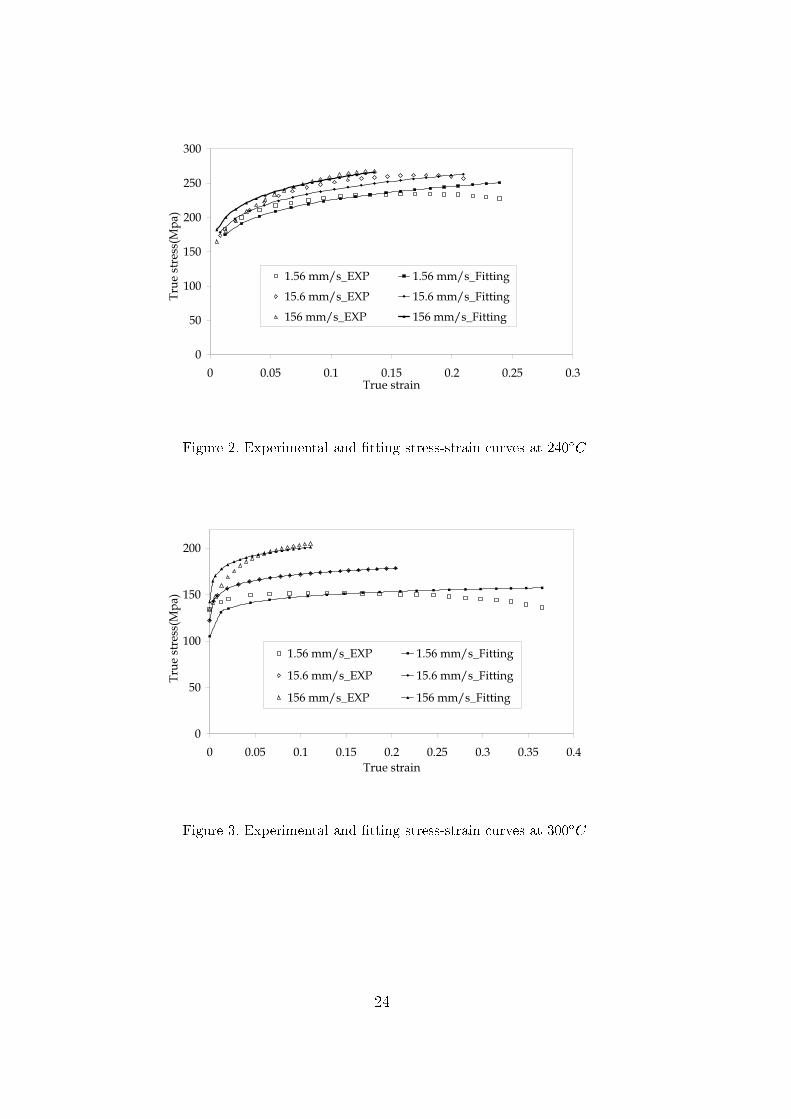
[Diot et al.(2006)Diot, Guines, Gavrus, and Ragneau℄. Hen e in this paper,the multipli ative Swift law � = K("0 + ")n _"m (1)has been hosen to des ribe the vis o-plasti behavior of this AA5083 alloy,where " and _" are the equivalent plasti strain and the equivalent plasti strain rate, respe tively. Here, n and m are the strain hardening and strainrate sensitivity indi es, and K and "0 are material parameters.To hara terize the high temperature deformation behavior of AA5083, tensiletests have been performed on a high-speed servo-hydrauli testing ma hine(DARTEC, 20kN apa ity) at temperatures of 150ÆC, 240ÆC and 300ÆC andthe onstant rosshead speeds of 1.56, 15.6 and 156 mm/s ( orresponding tointermediate strain rates from approximately 10�2 up to 10 s�1), respe tively.By the tensile tests, the true stress-true strain urves at 150ÆC, 240ÆC and300ÆC are obtained as shown in Fig.1, Fig.2 and Fig.3, respe tively. With theleast squares method, the orresponding parameter values of above onstitu-tive material model have been identi�ed to �t experimental data as shown inTab.1. Here, K, n and m are onsidered to be onstant for a given temper-ature and m is determined basing on the stress-strain urves with the threespeeds at this temperature. One an observe that AA5083 exhibits little strainrate sensitivity at 150ÆC (m = 0:0068), while this sensitivity learly augmentswith in rease of temperature. On the ontrary, with in reasing temperaturethe work hardening index n de reases. The orresponding �tting urves are ompared with experimental stress-strain urves in Fig.1, Fig.2 and Fig.3,respe tively.At 150ÆC, it is observed that the urves identi�ed with Swift's law are ingood agreement with experimental data. On the ontrary, at higher tem-peratures, some divergen es between experimental and identi�ed urves an7
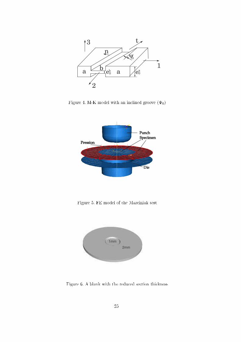
be observed, espe ially for lower forming speeds. The experimental urvesde line from the peak as strain pro eeds, while Swift's �tting urves al-ways give in reasing trends. The de lination of �ow stress with strain af-ter rea hing the peak stress is mainly attributed to material softening[Lee et al.(2004)Lee, Sohn, Kang, Suh, and Lee℄. Of parti ular interest for ushere is the e�e t of strain rate sensitivity on the forming apa ity of sheets,therefore, in this work, softening e�e t is not onsidered.3 M-K theoreti al model3.1 Brief des ription of the M-K modelThe typi al M-K geometri al model is shown in Fig.4. The imperfe tion isgeometri ally represented by a long groove whi h is hara terized by an initialimperfe tion fa tor f0 = eb0ea0 < 1; (2)where ea0 and eb0 are the initial sheet thi knesses in zone a and zone b, andthroughout the analysis the indi es a and b are used to designate the zonesoutside and inside the groove, respe tively.In the M-K original model introdu ed by Mar iniak and Ku zyn-ski [Mar iniak and Ku zynski(1967)℄, the groove is perpendi u-lar to the prin ipal stress, i.e.,0 = 0. Later, Hut hinson et al.[Hut hinson et al.(1978)Hut hinson, Neale, and Needleman℄ extendedthis model to strain paths in the negative minor strain region basedon a groove in lined at an angle 0 with respe t to the prin i-pal axis-2 (Fig.4). They put forward that the limit strains un-der uniaxial tension varied with initial groove orientation, as well8
as urrent orientation. For anisotropi materials, Barata Da Ro ha[Barata da Ro ha et al.(1984-1985)Barata da Ro ha, Barlat, and Jalinier℄also on luded that in most ases the riti al strains were a hieved for initialgroove orientations di�erent from zero. For the right side of FLDs, manyresear hers a hieved riti al strains with the simplisti model 0 = 0. Banabi and Dannenmann [Banabi and Dannenmann(2001)℄ applied Hill's 1993 yield riterion in the M-K model and analyzed the in�uen e of the yield urve shapeupon the right-hand side of FLDs. Avila and Vieira [Avila and Vieira(2003)℄developed an algorithm for predi tion of the right-hand side of FLDs basedon the M-K model. Five di�erent yield riteria (von Mises', Hill's 1948, Hill's1979, Hosford's and Hill's 1993) were implanted into this algorithm to analyzetheir in�uen e on FLDs.In the following work, the numeri al analysis of the M-K model for both ases(0 = 0 and 0 6= 0) is illustrated. For the left-hand side of FLDs, the ase0 6= 0 (general ase) is onsidered, while 0 = 0 (parti ular ase) is for theright-side of FLDs.Thanks to the sheet plane quasi-isotropy of AA5083, von Mises's yield fun tionunder plane stress assumption (�k13 = �k23 = �k33 = 0) an be used to modelthis sheet behavior��k�2 = ��k11�2 � �k11�k22 + ��k22�2 + 3 ��k12�2 ; (3)where �k is the equivalent stress, �k11, �k22 and �k12 are stress tensor omponents,k = a (or b).The sheet metal obeys Levy-Mises' �ow rule, whi h an be expressed in theform �"kij = ��k��kij�"k (i,j=1,2) ; (4)where �"kij and �"k are the strain omponent in rements and the equivalentplasti strain in rements, respe tively, and � refers to a hange orrespond-9
ing to a small time in rement �t. In addition, in ompressibility ondition isassumed during this analysis.In the M-K model, the same for e in the dire tion-n (Fig. 4) is transmitteda ross zones a and b. Therefore, the equilibrium equations are�annea = �bnneb; �antea = �bnteb; (5)where ea, eb are the urrent sheet thi knesses.The strain in zone b, parallel to the groove, is onstrained by the uniform zonea so that the ompatibility ondition is�"att = �"btt: (6)3.2 Parti ular ase (positive minor strain)The initial imperfe tion is assumed to be perpendi ular to the prin ipal axis-1,0 = 0, in the parti ular ase onsidered here. The groove referen e andmain axes system oin ide for both zones. The eqs.(5) and (6) redu e to�a11ea = �b11eb (7)and �"a22 = �"b22: (8)For the sake of onvenien e, the notations�k = �"k22�"k11 ; k = �k22�k11 = 2�k + 12 + �k'k = �k�k11 = q1� k + (k)2; �k = �"k�"k11 = 2'k2� k (9)10
related to von Mises' yield fun tion are introdu ed.The equivalent strain rate an be expressed in terms of the strain and timein rements as _"k = �"k�t : (10)With Swift's hardening law (1), the �ow rule (4) and the eqs.( 8-10), the eq.(7) an be expressed as("0 + "a + �a�"a11)n ('a)m�1(2a � 1)m = f �"0 + "b + �b�"b11�n �'b�m�1(2b � 1)m ; (11)where f is the urrent imperfe tion fa tor. Equation (11) shows that withthe disappearan e of time in rement, the level of strain rate has no e�e t inthe M-K model. Therefore, only the rate-sensitivity vis-à-vis the parameter m ould be analyzed for a given strain rate.Under the assumption of proportional loading in zone a, the strain path is hara terized by a onstant strain ratio �a. The parameter �"a11 is known.Therefore the terms k, 'k and �k are onstant for a ertain �a and anbe easily al ulated. For zone b the orresponding quantities vary with thestrain in rements but all an be expressed as fun tions of �"b11 by use of the ompatibility ondition.To al ulate �"b11, the fun tionF ��"b11� = ("0 + "a + �a�"a11)n 2b � 12a � 1!m�f �"0 + "b + �b�"b11�n 'b'a!m�1(12)is used. To numeri ally solve the equation F ��"b11� = 0, Newton-Raphson'smethod is used. The (i + 1)th iteration step is��"b11�(i+1) � ��"b11�(i) = � F ���"b11�(i)�dF=d���"b11�(i)� : (13)When absolute values of the in rement ��"b11�(i) be ome less than an error11
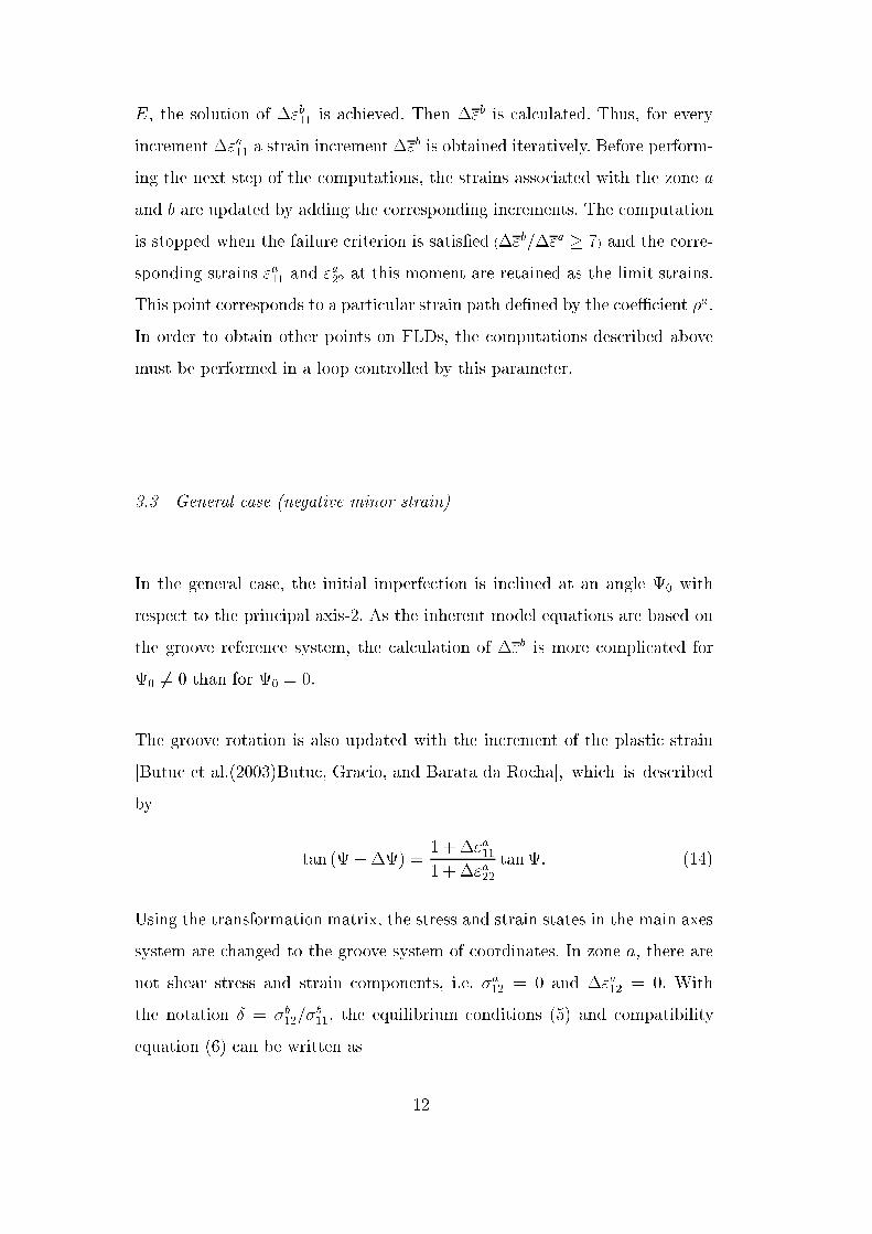
E, the solution of �"b11 is a hieved. Then �"b is al ulated. Thus, for everyin rement �"a11 a strain in rement �"b is obtained iteratively. Before perform-ing the next step of the omputations, the strains asso iated with the zone aand b are updated by adding the orresponding in rements. The omputationis stopped when the failure riterion is satis�ed (�"b=�"a � 7) and the orre-sponding strains "a11 and "a22 at this moment are retained as the limit strains.This point orresponds to a parti ular strain path de�ned by the oe� ient �a.In order to obtain other points on FLDs, the omputations des ribed abovemust be performed in a loop ontrolled by this parameter.3.3 General ase (negative minor strain)In the general ase, the initial imperfe tion is in lined at an angle 0 withrespe t to the prin ipal axis-2. As the inherent model equations are based onthe groove referen e system, the al ulation of �"b is more ompli ated for0 6= 0 than for 0 = 0.The groove rotation is also updated with the in rement of the plasti strain[Butu et al.(2003)Butu , Gra io, and Barata da Ro ha℄, whi h is des ribedby tan ( +�) = 1 +�"a111 + �"a22 tan: (14)Using the transformation matrix, the stress and strain states in the main axessystem are hanged to the groove system of oordinates. In zone a, there arenot shear stress and strain omponents, i.e. �a12 = 0 and �"a12 = 0. Withthe notation Æ = �b12=�b11, the equilibrium onditions (5) and ompatibilityequation (6) an be written as 12
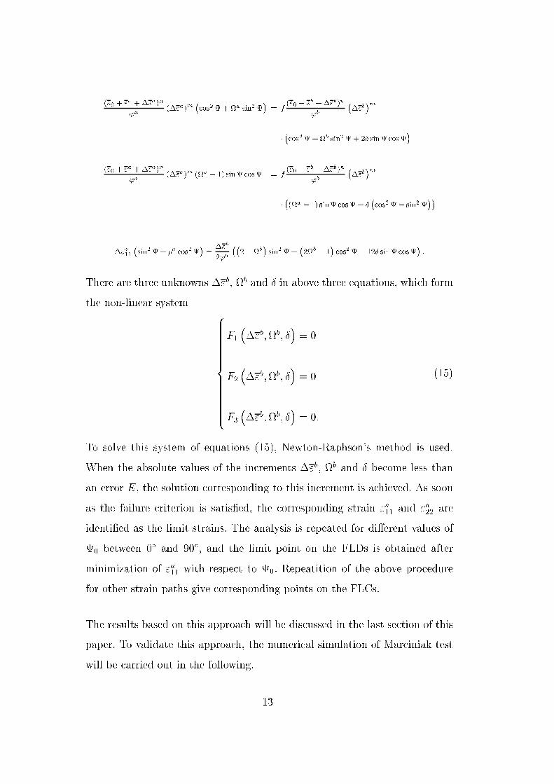
("0 + "a +�"a)n'a (�"a)m � os2+a sin2 � = f ("0 + "b +�"b)n'b ��"b�m�� os2+b sin2 + 2Æ sin os�("0 + "a +�"a)n'a (�"a)m (a � 1) sin os = f ("0 + "b +�"b)n'b ��"b�m��(a � 1) sin os + Æ � os2� sin2���"a11 �sin2 + �a os2� = �"b2'b ��2�b� sin2 + �2b � 1� os2 � 12Æ sin os� :There are three unknowns �"b, b and Æ in above three equations, whi h formthe non-linear system 8>>>>>>>>>>>>>><>>>>>>>>>>>>>>:F1 ��"b;b; Æ� = 0F2 ��"b;b; Æ� = 0F3 ��"b;b; Æ� = 0: (15)
To solve this system of equations (15), Newton-Raphson's method is used.When the absolute values of the in rements �"b, b and Æ be ome less thanan error E, the solution orresponding to this in rement is a hieved. As soonas the failure riterion is satis�ed, the orresponding strain "a11 and "a22 areidenti�ed as the limit strains. The analysis is repeated for di�erent values of0 between 0Æ and 90Æ, and the limit point on the FLDs is obtained afterminimization of "a11 with respe t to 0. Repeatition of the above pro edurefor other strain paths give orresponding points on the FLCs.The results based on this approa h will be dis ussed in the last se tion of thispaper. To validate this approa h, the numeri al simulation of Mar iniak testwill be arried out in the following. 13
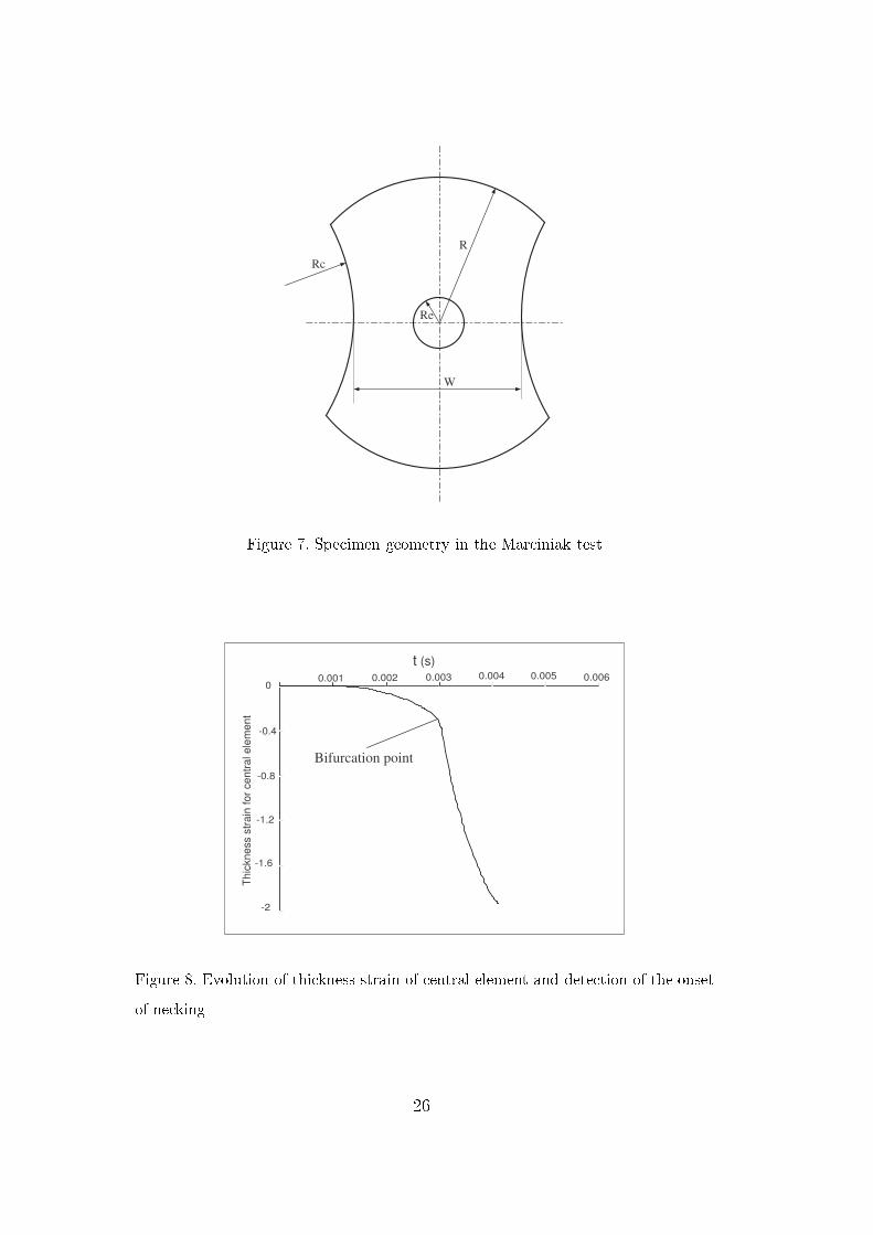
4 Numeri al method4.1 FE modelIn this part, the Mar iniak test is hosen to numeri ally analyze the formabilityof sheet metal. The �nite-element model for the Mar iniak test is omposed ofa rigid ylindri al pun h with a �at bottom, a die and a deformable sheet. Inaddition, a pressure load is dire tly applied on the sheet as the blank-holderfor e (Fig.5). Here, the use of a pressure rather than simply �xing the blankedge is to be as a ounterpart in future experiments.To assure the o urren e of maximal strains on the entral part of the blank,the spe imens are designed espe ially with a redu ed entral thi kness (1 mm), ompared to the thi kness of the sheet (2.0 mm) as shown in Fig.6.The Mar iniak test requires the appli ation of various spe imen geometriesfor the determination of di�erent strain states, ranging from uniaxial throughplane strain to balan ed biaxial. In the present paper, the geometry and di-mensions of spe imen are shown in Fig.7 and Tab.2.The analysis is arried out with the ommer ially available �nite-element pro-gram ABAQUS with shell linear elements S4R. Due to symmetri al boundary onditions, only the quarter of the entire model is simulated. The elasti ity ofthe spe imen is de�ned with a Young's modulus of 70000 MPa and a Poisson'sratio of 0.3. The onstitutive law (1) is implemented into ABAQUS by usingan UHARD user subroutine.The onta t intera tion is modeled using Coulomb's law: fri tion oe� ientfor pun h-blank is 0.05; while blank-die fri tion value is hosen to 0.5. Thespeed of the pun h during the stamping pro edure is 5 m/s.14
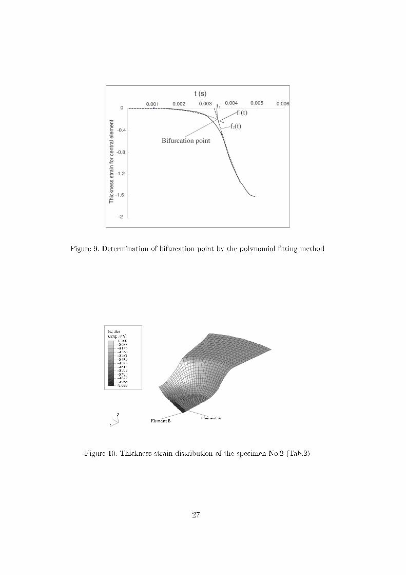
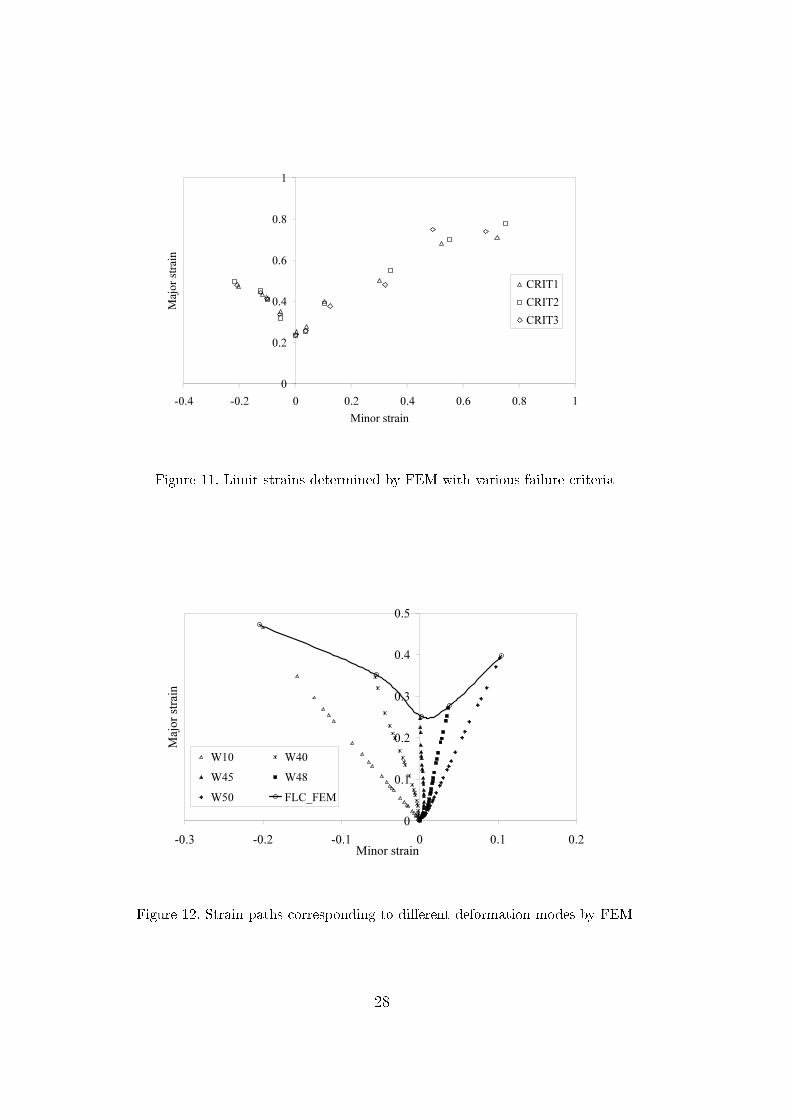
4.2 Failure riterionHereafter, we take the spe imen No.2 in Tab.2 as an example to illustratethe analysis pro ess. The rheologi al parameter values used in this simulation orrespond to the material behavior data of AA5083 at 150ÆC with m = 0:01.These values serve also as a basis for the following parametri studies.Be ause the o urren e of the plasti instabilities is determined by lo alizedne king whose size is of the order of the sheet thi kness, the thi kness strain an be used in a lo al riterion to evaluate the o urren e of ne king (CRIT1).If the ne king o urs, a sharp hange of thi kness strain an be observed, thensheet metal will su�er drasti deformation (Fig.8). This plasti instability orresponds to a bifur ation point, i.e. the interse tion point of two bifur- ation bran hes. When a sharp hange of thi kness strain annot be learlyobserved, as shown in Fig.9, a polynomial urve �tting method is employed.Here, f1(t) and f2(t) are two 3rd-degree polynomial fun tions and representthe �tting urves of the two bran hes, respe tively. Then time oordinate t1of the interse tion point is al ulated. Based on the FEM results, the majorand minor strains at this moment are obtained by linear interpolation of the loser al ulated strain values. Due to the redu ed thi kness of the entralpart, the maximum thi kness strain generally �rst o urs at the enter of thesheet (Fig.10). Moreover, after the onset of ne king, the level of strain remains onstant in the other adja ent elements.In order to hoose an appropriate riterion for the dete tion of ne king,two additional lo al riteria are evaluated: maximum se ond strain derivative(CRIT2) and equivalent plasti strain in rement ratio (CRIT3). For CRIT2,the o urren e of the sharp variation of thi kness strain is onsidered asthe onset of lo alized ne king and then the se ond temporal derivative ofthi kness strain must present a peak at this moment. A ording to Petek'smethod [Petek et al.(2005)Petek, Pepelnjak, and Kuzman℄, the se ond tem-15
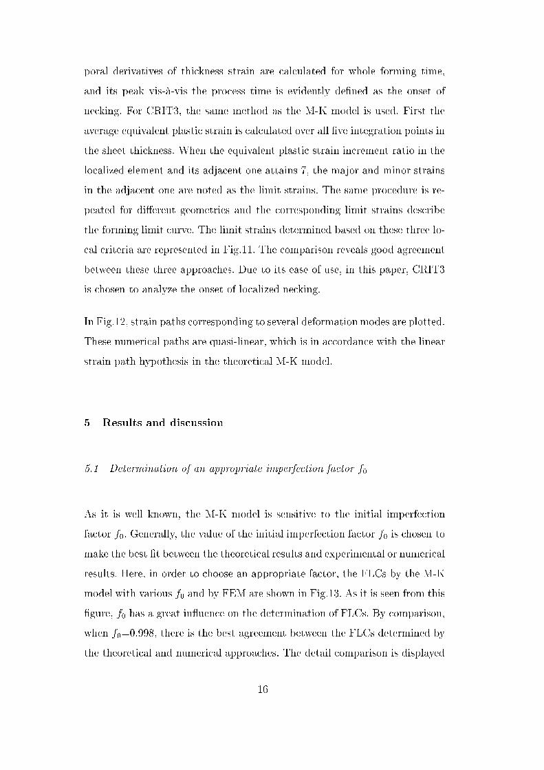
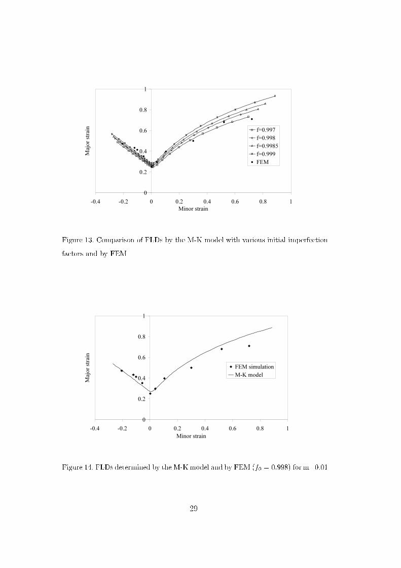
poral derivatives of thi kness strain are al ulated for whole forming time,and its peak vis-à-vis the pro ess time is evidently de�ned as the onset ofne king. For CRIT3, the same method as the M-K model is used. First theaverage equivalent plasti strain is al ulated over all �ve integration points inthe sheet thi kness. When the equivalent plasti strain in rement ratio in thelo alized element and its adja ent one attains 7, the major and minor strainsin the adja ent one are noted as the limit strains. The same pro edure is re-peated for di�erent geometries and the orresponding limit strains des ribethe forming limit urve. The limit strains determined based on these three lo- al riteria are represented in Fig.11. The omparison reveals good agreementbetween these three approa hes. Due to its ease of use, in this paper, CRIT3is hosen to analyze the onset of lo alized ne king.In Fig.12, strain paths orresponding to several deformationmodes are plotted.These numeri al paths are quasi-linear, whi h is in a ordan e with the linearstrain path hypothesis in the theoreti al M-K model.5 Results and dis ussion5.1 Determination of an appropriate imperfe tion fa tor f0As it is well known, the M-K model is sensitive to the initial imperfe tionfa tor f0. Generally, the value of the initial imperfe tion fa tor f0 is hosen tomake the best �t between the theoreti al results and experimental or numeri alresults. Here, in order to hoose an appropriate fa tor, the FLCs by the M-Kmodel with various f0 and by FEM are shown in Fig.13. As it is seen from this�gure, f0 has a great in�uen e on the determination of FLCs. By omparison,when f0=0.998, there is the best agreement between the FLCs determined bythe theoreti al and numeri al approa hes. The detail omparison is displayed16
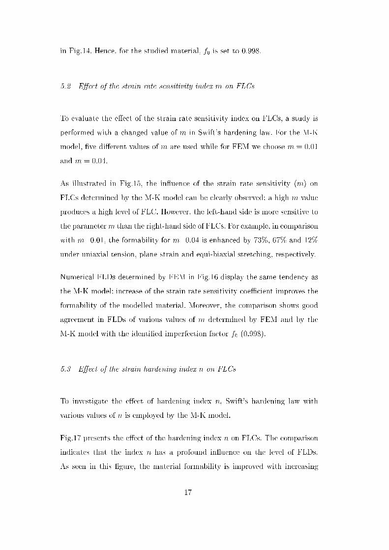
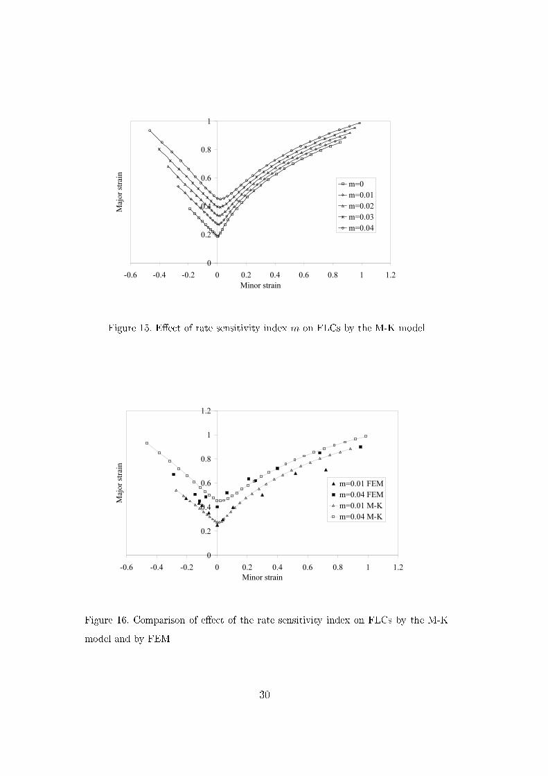
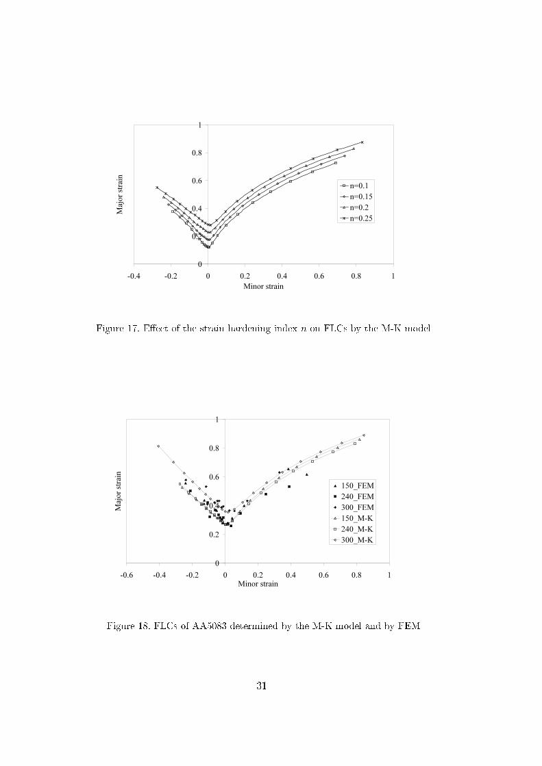
in Fig.14. Hen e, for the studied material, f0 is set to 0.998.5.2 E�e t of the strain rate sensitivity index m on FLCsTo evaluate the e�e t of the strain rate sensitivity index on FLCs, a study isperformed with a hanged value of m in Swift's hardening law. For the M-Kmodel, �ve di�erent values of m are used while for FEM we hoose m = 0:01and m = 0:04.As illustrated in Fig.15, the in�uen e of the strain rate sensitivity (m) onFLCs determined by the M-K model an be learly observed: a high m valueprodu es a high level of FLC. However, the left-hand side is more sensitive tothe parameterm than the right-hand side of FLCs. For example, in omparisonwith m=0.01, the formability for m=0.04 is enhan ed by 73%, 67% and 12%under uniaxial tension, plane strain and equi-biaxial stret hing, respe tively.Numeri al FLDs determined by FEM in Fig.16 display the same tenden y asthe M-K model: in rease of the strain rate sensitivity oe� ient improves theformability of the modelled material. Moreover, the omparison shows goodagreement in FLDs of various values of m determined by FEM and by theM-K model with the identi�ed imperfe tion fa tor f0 (0.998).5.3 E�e t of the strain hardening index n on FLCsTo investigate the e�e t of hardening index n, Swift's hardening law withvarious values of n is employed by the M-K model.Fig.17 presents the e�e t of the hardening index n on FLCs. The omparisonindi ates that the index n has a profound in�uen e on the level of FLDs.As seen in this �gure, the material formability is improved with in reasing17
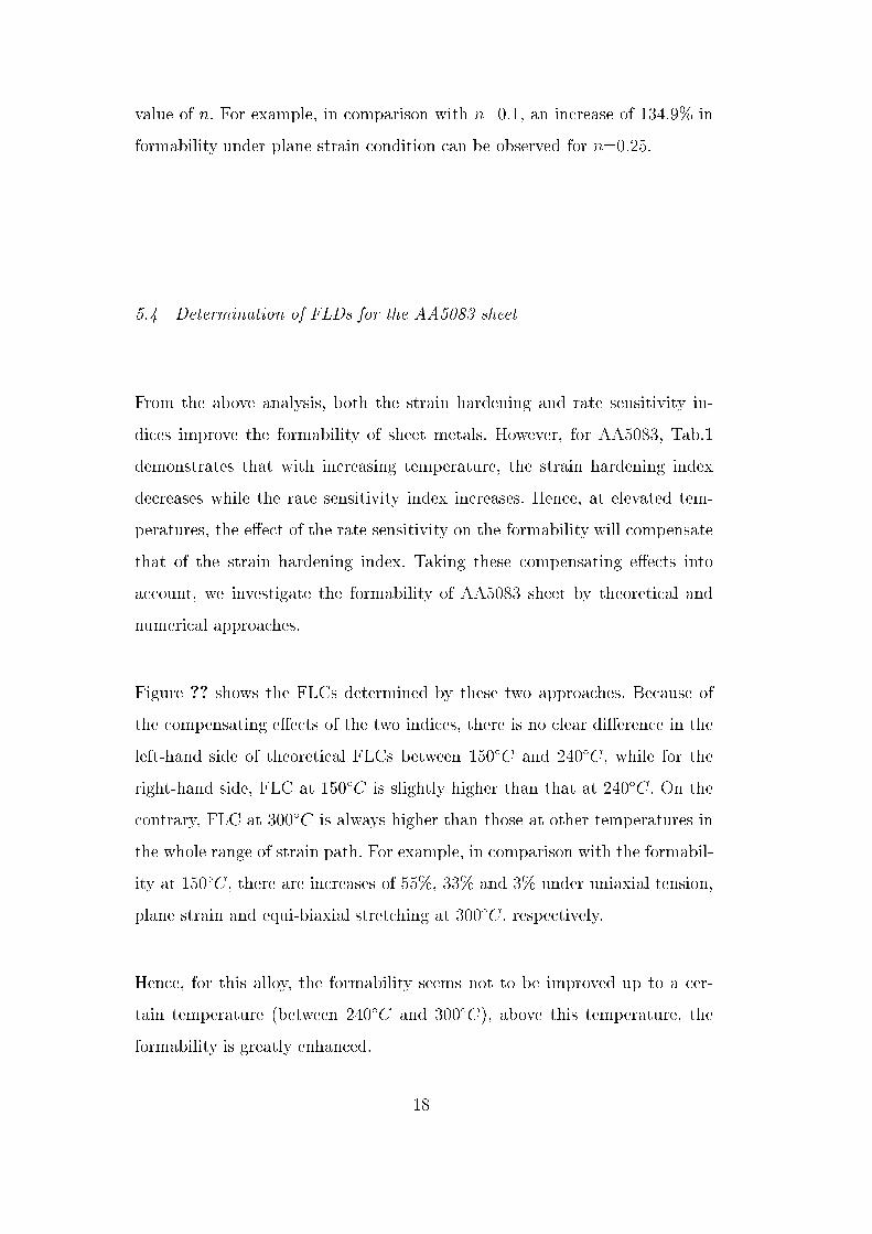
value of n. For example, in omparison with n=0.1, an in rease of 134.9% informability under plane strain ondition an be observed for n=0.25.5.4 Determination of FLDs for the AA5083 sheetFrom the above analysis, both the strain hardening and rate sensitivity in-di es improve the formability of sheet metals. However, for AA5083, Tab.1demonstrates that with in reasing temperature, the strain hardening indexde reases while the rate sensitivity index in reases. Hen e, at elevated tem-peratures, the e�e t of the rate sensitivity on the formability will ompensatethat of the strain hardening index. Taking these ompensating e�e ts intoa ount, we investigate the formability of AA5083 sheet by theoreti al andnumeri al approa hes.Figure ?? shows the FLCs determined by these two approa hes. Be ause ofthe ompensating e�e ts of the two indi es, there is no lear di�eren e in theleft-hand side of theoreti al FLCs between 150ÆC and 240ÆC, while for theright-hand side, FLC at 150ÆC is slightly higher than that at 240ÆC. On the ontrary, FLC at 300ÆC is always higher than those at other temperatures inthe whole range of strain path. For example, in omparison with the formabil-ity at 150ÆC, there are in reases of 55%, 33% and 3% under uniaxial tension,plane strain and equi-biaxial stret hing at 300ÆC, respe tively.Hen e, for this alloy, the formability seems not to be improved up to a er-tain temperature (between 240ÆC and 300ÆC), above this temperature, theformability is greatly enhan ed. 18
6 Con lusionIn this paper, the sheet formability is investigated by the theoreti al M-Kmodel and by a numeri al method. For the numeri al method, the di� ultyis to establish a pertinent riterion for dete ting the onset of ne king. Theproposed riterion, similarly to that in the M-K model, is based on the equiv-alent plasti strain in rement ratio in the lo alized element and its adja entone. Moreover, this riterion predi ts the onset of lo alized ne king with theprin ipal strains, therefore it is easy to use for experimental determination ofFLDs. Then from the omparison between the theoreti al and numeri al re-sults, an appropriate initial imperfe tion fa tor of the M-K model is identi�ed(f0 = 0:998). By means of parametri studies based on the above two ap-proa hes, the e�e t of strain hardening index n and the rate sensitivity indexm on FLCs are observed: the formability is in reased with in rease of n andm. Finally, by onsideration of the ompensating e�e ts of the strain harden-ing and rate sensitivity indi es, FLDs of AA5083 sheet are onstru ted by theM-K model and by FEM. Results show that the formability of this alloy seemsnot to be improved up to a ertain temperature, above this temperature, theformability is greatly enhan ed.The results must be experimentally validated in order to determine a urateFLDs ne essary and optimize the forming pro esses in whi h the strain ratesensitivity should be onsidered. This validation is in progress by means ofa dynami Mar iniak test asso iated with a high speed amera and the dig-ital image orrelation te hnique to dete t the onset of lo alized ne king and onstru t FLDs. 19
Referen es[Arrieux(1990)℄ Arrieux, R., 1990. Détermination théorique et expérimentale des ourbes limites de formage en ontraintes. Ph.D. thesis, INSA de Lyon.[Avila and Vieira(2003)℄ Avila, A. F., Vieira, E., 2003. Proposing a better forminglimit diagram predi tion - a omparative study. Journal of Materials Pro essingTe hnology 141, 101�108.[Banabi and Dannenmann(2001)℄ Banabi , D., Dannenmann, E., 2001. Predi tionof the in�uen e of yield lo us on the limit strains in sheet metals. Journal ofMaterials Pro essing Te hnology 109, 9�12.[Barata da Ro ha et al.(1984-1985)Barata da Ro ha, Barlat, and Jalinier℄Barata da Ro ha, A., Barlat, F., Jalinier, J., 1984-1985. Predi tion of theforming limit diagrams of anisotropi sheets in linear and non-linear loading.Materials S ien e and Engineering 68, 151�164.[Broomhead and Grieve(1982)℄ Broomhead, P., Grieve, R., 1982. The e�e t of strainrate on the strain to fra ture of a sheet steel under biaxial tensile stress onditions. Journal of Engineering Materials and Te hnology 104, 102�106.[Brun et al.(1999)Brun, Chambard, Lai, and De Lu a℄ Brun, R., Chambard, A.,Lai, M., De Lu a, P., 1999. A tual and virtual testing te hniques for a numeri alde�nition of materials. In: Pro eedings of NUMISHEET '99, Besançon, Fran e.pp. 393�398.[Butu et al.(2003)Butu , Gra io, and Barata da Ro ha℄ Butu , M., Gra io, J.,Barata da Ro ha, A., 2003. A theoreti al study on forming limit diagramspredi tion. Journal of Materials Pro essing Te hnology 142, 714�724.[Diot et al.(2006)Diot, Guines, Gavrus, and Ragneau℄ Diot, S., Guines, D., Gavrus,A., Ragneau, E., 2006. Forming pro ess of a 5083 aluminium alloy. onstitutivemodel overing a large range of temperature. International Journal of FormingPro esses 9, 167�188. 20
[Geiger and Merklein(2003)℄ Geiger, M., Merklein, M., 2003. Determination offorming limit diagrams - a new analysis method for hara terization of materials'formability. Annals of the CIRP 52, 213�216.[Graf and Hosford(1990)℄ Graf, A., Hosford, W., 1990. Cal ulations of forming limitdiagrams. Metallurgi al Transa tions A 21A, 87�93.[Hill(1952)℄ Hill, R., 1952. On dis ontinuous plasti states, with spe ial referen e tolo alized ne king in thin sheets. Journal of the Me hani s and Physi s of Solids1, 19�30.[Hut hinson et al.(1978)Hut hinson, Neale, and Needleman℄ Hut hinson, J., Neale,K., Needleman, A., 1978. Me hani s of sheet metal forming. New York/London,Plenum Press, pp. 269�285.[Keeler and Ba kofen(1963)℄ Keeler, S., Ba kofen, W., 1963. Plasti instability andfra ture in sheets stret hed over rigid pun hes. Trans. ASM 56, 25�48.[Laukonis and Ghosh(1978)℄ Laukonis, J., Ghosh, A., 1978. E�e ts of strain path hanges on the formability of sheet metals. Metallurgi al Transa tions A 9A,1849�1856.[Lee and Zaverl(1982)℄ Lee, D., Zaverl, F., 1982. Ne king growth and forming limitsin sheet metals. International Journal of Me hani al S ien es 24, 157�173.[Lee et al.(2004)Lee, Sohn, Kang, Suh, and Lee℄ Lee, M., Sohn, S., Kang, C., Suh,D., Lee, S., 2004. E�e ts of pre-treatment onditions on warm hydroformabilityof 7075 aluminum tubes. Journal of Materials Pro essing Te hnology 155-156,1337�1343.[Mar iniak and Ku zynski(1967)℄ Mar iniak, Z., Ku zynski, K., 1967. Limit strainsin the pro esses stret h-forming sheet metal. International Journal of Me hani alS ien es 9, 609�620.[Narasimhan(2004)℄ Narasimhan, K., 2004. A novel riterion for predi ting forminglimit strains. In: Ghosh, S., Castro, J., Lee, J. (Eds.), Materials Pro essing andDesign: Modeling, Simulation and Appli ations. NUMIFORM 2004 Pro eedings21
of the 8th International Conferen e on Numeri al Methods in Industrial FormingPro esses. Vol. 2. Ameri an Institute of Physi s, pp. 850�855.[Nie and Lee(1991)℄ Nie, Q., Lee, D., 1991. The e�e t of rate-sensitivity on historydependent forming limit of anisotropi sheet metals. Journal of MaterialsShaping Te hnology 9, 233�240.[Per y(1980)℄ Per y, J., 1980. The e�e t of strain rate on the FLD for sheet metal.Annals of the CIRP 29, 151�152.[Petek et al.(2005)Petek, Pepelnjak, and Kuzman℄ Petek, A., Pepelnjak, T.,Kuzman, K., 2005. An improved method for determining forming limit diagramin the digital enviroment. Journal of Me hani al Engineering 51, 330�345.[Stoughton(2001)℄ Stoughton, T., 2001. Stress-based forming limits in sheet-metalforming. Journal of Engineering Materials and Te hnology 123, 417�422.[Swift(1952)℄ Swift, H., 1952. Plasti instability under plane stress. Journal of theMe hani s and Physi s of Solids 1, 1�18.[Volk(2006)℄ Volk, W., 2006. New experimental and numeri al approa h in theevaluation of the FLD with the FE-method. In: Pro eedings of the FLC-Zuri h06, Zuri h, Switzerland.[Zadpoor et al.(2007)Zadpoor, Sinke, and Benedi tus℄ Zadpoor, A., Sinke,J., Benedi tus, R., 2007. Predi tion of limit strains in limiting dome heightformability test. In: Cueto, E., Chinesta, F. (Eds.), 10th ESAFORM onferen eon material forming. Ameri an Institute of Physi s, pp. 258�263.22
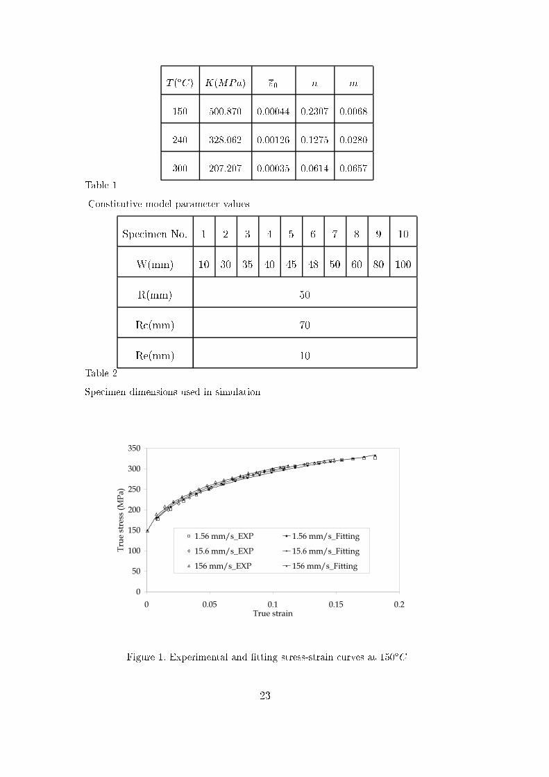
T (ÆC) K(MPa) "0 n m150 500.870 0.00044 0.2307 0.0068240 328.062 0.00126 0.1275 0.0280300 207.207 0.00035 0.0614 0.0657Table 1Constitutive model parameter valuesSpe imen No. 1 2 3 4 5 6 7 8 9 10W(mm) 10 30 35 40 45 48 50 60 80 100R(mm) 50R (mm) 70Re(mm) 10Table 2Spe imen dimensions used in simulation
0
50
100
150
200
250
300
350
0 0.05 0.1 0.15 0.2True strain
Tru
e st
ress
(M
Pa
)
1.56 mm/s_EXP 1.56 mm/s_Fitting
15.6 mm/s_EXP 15.6 mm/s_Fitting
156 mm/s_EXP 156 mm/s_Fitting
Figure 1. Experimental and �tting stress-strain urves at 150ÆC23
0
50
100
150
200
250
300
0 0.05 0.1 0.15 0.2 0.25 0.3True strain
Tru
e st
ress
(Mp
a)
1.56 mm/s_EXP 1.56 mm/s_Fitting
15.6 mm/s_EXP 15.6 mm/s_Fitting
156 mm/s_EXP 156 mm/s_Fitting
Figure 2. Experimental and �tting stress-strain urves at 240ÆC
0
50
100
150
200
0 0.05 0.1 0.15 0.2 0.25 0.3 0.35 0.4
True strain
Tru
e st
ress
(Mp
a)
1.56 mm/s_EXP 1.56 mm/s_Fitting
15.6 mm/s_EXP 15.6 mm/s_Fitting
156 mm/s_EXP 156 mm/s_Fitting
Figure 3. Experimental and �tting stress-strain urves at 300ÆC24
n
t
1
2
3
ab
0ψ
a eb0 e
a0
Figure 4. M-K model with an in lined groove (0)
Figure 5. FE model of the Mar iniak test1mm
2mm
Figure 6. A blank with the redu ed se tion thi kness25
R
Re
Rc
W
Figure 7. Spe imen geometry in the Mar iniak test
-2
-1.6
-1.2
-0.8
-0.4
00.001 0.002 0.003 0.004 0.005 0.006
Bifurcation point
t (s)
Thic
kness s
train
for
centr
al ele
ment
Figure 8. Evolution of thi kness strain of entral element and dete tion of the onsetof ne king26
t (s)
Th
ickn
ess s
tra
in f
or
ce
ntr
al e
lem
en
tt1
f2(t)
f1(t)
Bifurcation point
-2
-1.6
-1.2
-0.8
-0.4
00.001 0.002 0.003 0.004 0.005 0.006
Figure 9. Determination of bifur ation point by the polynomial �tting method
Figure 10. Thi kness strain distribution of the spe imen No.2 (Tab.2)27
0
0.2
0.4
0.6
0.8
1
-0.4 -0.2 0 0.2 0.4 0.6 0.8 1
Minor strain
Maj
or
stra
in
CRIT1
CRIT2
CRIT3
Figure 11. Limit strains determined by FEM with various failure riteria
0
0.1
0.2
0.3
0.4
0.5
-0.3 -0.2 -0.1 0 0.1 0.2
Minor strain
Maj
or
stra
in
W10 W40
W45 W48
W50 FLC_FEM
Figure 12. Strain paths orresponding to di�erent deformation modes by FEM28
0
0.2
0.4
0.6
0.8
1
-0.4 -0.2 0 0.2 0.4 0.6 0.8 1
Minor strain
Maj
or
stra
in f=0.997
f=0.998
f=0.9985
f=0.999
FEM
Figure 13. Comparison of FLDs by the M-K model with various initial imperfe tionfa tors and by FEM
0
0.2
0.4
0.6
0.8
1
-0.4 -0.2 0 0.2 0.4 0.6 0.8 1
Minor strain
Maj
or
stra
in
FEM simulation
M-K model
Figure 14. FLDs determined by the M-K model and by FEM (f0 = 0:998) for m=0.0129
0
0.2
0.4
0.6
0.8
1
-0.6 -0.4 -0.2 0 0.2 0.4 0.6 0.8 1 1.2
Minor strain
Maj
or
stra
in
m=0
m=0.01
m=0.02
m=0.03
m=0.04
Figure 15. E�e t of rate sensitivity index m on FLCs by the M-K model
0
0.2
0.4
0.6
0.8
1
1.2
-0.6 -0.4 -0.2 0 0.2 0.4 0.6 0.8 1 1.2
Minor strain
Maj
or
stra
in
m=0.01 FEM
m=0.04 FEM
m=0.01 M-K
m=0.04 M-K
Figure 16. Comparison of e�e t of the rate sensitivity index on FLCs by the M-Kmodel and by FEM30
0
0.2
0.4
0.6
0.8
1
-0.4 -0.2 0 0.2 0.4 0.6 0.8 1
Minor strain
Maj
or
stra
in
n=0.1
n=0.15
n=0.2
n=0.25
Figure 17. E�e t of the strain hardening index n on FLCs by the M-K model
0
0.2
0.4
0.6
0.8
1
-0.6 -0.4 -0.2 0 0.2 0.4 0.6 0.8 1Minor strain
Maj
or
stra
in
150_FEM
240_FEM
300_FEM
150_M-K
240_M-K
300_M-K
Figure 18. FLCs of AA5083 determined by the M-K model and by FEM31