numerical modelling in large strain plasticity with
TRANSCRIPT

NUMERICAL MODELLING IN LARGE STRAIN PLASTICITY
WITH APPLICATION TO TUBE COLLAPSE ANALYSIS
By
JOSEsM. GOICOLEA RUIGOMEZ
Ing. Caminos
A Thesis submitted for the degree of
Doctor of Philosophy
In the Faculty of Engineering of the
University of London
King 's College London
October 1985

2
ABSTRACT
Numerical methods are proposed f o r the ana lys is of 2 or 3-
dimensional la rge s t r a i n p l a s t i c i t y problems. A F i n i t e D i f f e rence
program, w i t h 2-d imensional cont inuum elements and e x p l i c i t t ime
in tegra t ion , has been developed and applied to model the axisymmetric
crumpling of c i r cu la r tubes.
New types of mi xed el ements (Tr iangles-Quadr i la tera ls for 2-D,
T e t r a h e d r a - B r i c k s f o r 3-D) are p roposed f o r t he s p a t i a l
d i sc re t i za t i on . These elements model accurately incompressible p las t ic
f low, without unwanted "zero-energy" de fo rmat ion modes or t a n g l i n g
over of the mesh. E l a s t i c - p l a s t i c , ra te dependent laws are modelled
wi th a "radial return" algor i thm. The transmission of heat generated
by p l a s t i c work and mate r ia l dependence on temperature are a lso
included, enabling a f u l l y coupled thermo-mechanical analysis.
A 2-D and ax isymmetr ic computer program has been developed,
implement ing the numerical techniques descr ibed . Computat ional
e f f i c i e n c y was e s s e n t i a l , as la rge sca le , c o s t l y a p p l i c a t i o n s were
intended. An important part of the program was the contact a lgor i thm,
enabling the modelling of in terac t ion between surfaces.
The ax isymmetr ic c rump l ing of tubes under a x i a l compression
( "concer t ina" mode) has been analyzed Numer i ca l l y . Q u a s i - s t a t i c
experiments on Aluminium tubes were modelled, using ve loc i ty scal ing.
Mery large s t r a i n s are developed in the c rump l ing process; w i t h the
help of tension tes ts , material laws va l id for such s t ra in ranges were
developed. Good agreement was obtained between numerical predict ions
and experimental resul ts . Modelling choices such as mesh refinement,
element type and veloc i ty scal ing were studied, and found to have an
impor tan t i n f l u e n c e on the numerical p r e d i c t i o n s . F i n a l l y , a l a rge
scale impact ana lys i s of a s tee l tube at 176m/s was per formed. The
resul ts compared wel l w i th experiment, ind ica t ing dif ferences w i th the
behaviour of low ve loc i ty crumpling mechanisms.
To conclude, F i n i t e D i f f e rence procedures w i t h e x p i i c i t t i m e -

3
marching techniques are proposed for large s t ra in p l a s t i c i t y problems,
at low or medium impact v e l o c i t i e s . A f a i r l y robust code has been
developed and applied successful ly to a range of large s t ra in and tube
crumpling problems.

4
ACKNOWLEDGEMENTS
I wish to express my sincere grat i tude to the fo l low ing :
Dr. G.L. England who superv ised t h i s work, f o r h is constant support
and guidance throughout the period of research;
Dr. J. Mar t i from P r i n c i p i a , f o r h is i nva luab le expert advice on
t h e o r e t i c a l and numer ical ma t t e r s , and h is f r i e n d l y support and
suggestions;
Or. £. A la rcon , f o r h is help and mo t i va t i on in the i n i t i a l stages of
work;
The s t a f f and techn ic ians of the C i v i l Engineer ing Department at
King's College, for t he i r help and cooperation;
My w i fe , Tereca Marin, for her help in the preparation of f igures , and
her unending patience and encouragement during the research period.
I would also l i k e to thank the fo l low ing bodies for sponsoring my
research at the var ious s tages: The B r i t i s h Counc i l , The Spanish
Government (Ministry of Education), Pr inc ip ia Mechanica Ltd. (UK), and
the Committee of Vicechancellors and Pr incipals (UK).

TABLE OF CONTENTS
Pa
TITLE
ABSTRACT
ACKNOWLEDGEMENTS
TABLE OF CONTENTS
BASIC NOTATION 10
CHAPTER 1 - INTRODUCTION 13
1.1 Objectives 14
1.2 Non-l inear modelling 16
1.3 Layout 17
CHAPTER 2 - CONTINUUM MECHANICS DESCRIPTIONS 18
2.1 Introduction 19
2.2 Kinematics 20
2.2.1 Configurations 21
2.2.2 Deformation tensors 21
2.2.3 Deformation and spin rates 23
2.2.4 Strains 23
2.2.5 Transformations 24
2.3 Stress 25
2.3.1 Cauchy 25
2.3.2 Piola-Kirchhoff 25
2.4 Balance laws 26
2.4.1 Balance of momentum 26

Pa
2.4.2 Balance of mass 26
2.4.3 Balance of energy 27
2.5 Constitutive relations 28
2.5.1 Rate equations 29
2.5.2 Elasticity 30
2.5.2.1 Hyperelastic materials 31
2.5.2.2 Hypoelastic materials 31
2.5.3 Plasticity 32
2.5.3.1 Von Mises model 34
2.5.3.2 Other plasticity models 35
CHAPTER 3 - NON-LINEAR NUMERICAL MODELS FOR SOLID MECHANICS 37
3.1 Introduction 38
3.2 Finite Difference methods 39
3.3 Finite Element methods 41
3.4 Mesh descriptions 44
3.4.1 Lagrangian 44
3.4.2 Eulerian 45
3.4.3 Arbitrary Lagrangian-Eulerian 45
3.5 Large displacement formulations 46
3.5.1 Total Lagrangian 46
3.5.2 Cauchy stress - velocity strain 47
3.5.3 Updated Lagrangian 49
3.6 Time integration 49
3.6.1 Central Difference (explicit) 50
3.6.2 Trapezoidal rule (implicit) 52
3.6.3 Operator split methods 54
3.7 Practical considerations for discrete mehes 55
3.7.1 "Locking-up" for incompressible flow 55
3.7.2 "Hourglassing" 58
3.8 Conclusions 59
CHAPTER 4 - EXPLICIT FINITE DIFFERENCE NUMERICAL MODEL 61
4.1 Introduction 63

Pa
4.1.1 General methodology 63
4.2 Spatial semidiscretization 66
4.2.1 Constant Strain Triangles and Tetrahedra (CST elements) 67
4.2.2 Mixed Discretization (MTQ, MTB elements) 72
4.2.3 Prevention of negative volumes (MTQC, MTBC elements) 75
4.2.4 Mass lumping procedure 78
4.3 Momentum balance 78
4.4 Central difference time integration 79
4.5 Constitutive models 79
4.5.1 Hypoelasticity 80
4.5.2 Plasticity; radial return algorithm 80
4.5.3 Hardening and uniaxial stress-strain laws 84
4.5.4 Objective stress rates 87
4.6 Damping 88
4.7 Stability of time integration 90
4.8 Modelling of contacts 91
4.8.1 Contact interface laws 92
4.8.2 Contact detection algorithm 94
4.9 Heat conduction 96
4.10 Energy computations 100
4.11 Implementation into Fortran program 102
CHAPTER 5 - BENCHMARKS AND VALIDATION EXAMPLES 106
5.1 Introduct ion 107
5.2 Wave propagation 107
5.2.1 Elast ic waves in bars 107
5.2.2 E las t i c -p las t i c waves 110
5.2.3 Elast ic waves in cone 112
5.3 Vibrat ion of a cant i lever 114
5.4 Stat ic e l as t i c - p l as t i c problems 117
5.4.1 Punch test 117
5.4.2 E las t i c -p las t i c sphere under in ternal pressure 121
5.5 Heat conduction 123
5.5.1 Coupled thermomechanical analysis 123
5.5.2 Temperature red is t r i bu t i on in a slab 124
5.6 Large stra ins and rotat ions 124

Pa
5.7 Impact of cy l inder 126
5.8 Conclusions 128
CHAPTER 6 - TENSION TESTS ON ALUMINUM BARS 129
6.1 Introduction 130
6.1.1 Constitutive idealization 132
6.1.2 Tension tests - a review 133
6.2 Theoretical interpretation of tension tests 136
6.2.1 Strain distribution at minimum neck section 137
6.2.2 Stress distribution 138
6.3 Tension tests 140
6.3.1 Specimens and material 140
6.3.2 Programme 141
6.3.3 Procedure 142
6.3.4 Results 142
6.3.5 Microhardness tests 144
6.4 Material hardening law 147
6.5 Numerical calculations for tension tests 151
6.5.1 Model 151
6.5.2 Analysis 153
6.5.3 Results 154
6.6 Conclusions 156
CHAPTER 7 - CONCERTINA TUBE COLLAPSE ANALYSIS 164
7.1 In t roduc t ion 166
7 .1 .1 Scope 166
7.2 Overview of energy d iss ipat ing devices 167
7.2.1 Def in i t ion and c r i t e r i a 167
7.2.2 Types of energy d iss ipat ing devices 168
7.2.3 Tubes as energy absorbers 169
7.2.3.1 Lateral compression 169
7.2.3.2 Axisymmetric axial crumpling 170
7.2.3.3 Diamond-fold axial crumpling 171
7.2.3.4 Tube inversion 171

Page
7.3 Quasi-stat ic concertina tube collapse mechanisms 172
7.3.1 Related experimental work 172
7.3.1.1 Experimental programme and method 173
7.3.1.2 Typical experimental results 174
7.3.1.3 Microhardness tests 177
7.3.1.3.1 Equipment and procedure 177
7.3.1.3.2 Derivation of material strength, Y 178
7.3.2 Numerical model 182
7.3.2.1 Discretization and material 183
7.3.2.2 Velocity scaling 184
7.3.2.3 Interpretation of output 185
7.3.3 Results form numerical calculations and experiment 187
7.3.3.1 Tube geometry A: ID=19.05mm, t=1.64mm, L=50.8mm 188
7.3.3.2 Tube geometry B: ID=19.05mm, t=1.17mm, L=50.8mm 193
7.3.3.3 Tube geometry C: 0D=38.10mm, t=1.65mm, L=50.8mm 197
7.3.3.4 Tube geometry D: 0D=25.40mm, t=0.95mm, L=25.4mm 203
7.3.4 Parametric studies in numerical analyses 208
7.3.4.1 Influence of friction 208
7.3.4.2 Influence of velocity scaling 213
7.3.4.3 Influence of mesh refinement 216
7.3.4.4 Influence of element type 223
7.3.5 Discussion 228
7.4 Medium velocity (176m/s) tube impact analysis 233
7.4.1 Description of problem 233
7.4.2 Numerical idealization 235
7.4.3 Numerical results 237
7.4.4 Discussion 243
7.5 Conclusions 249
CHAPTER 8 - CONCLUSIONS AND SUGGESTIONS FOR FURTHER RESEARCH 251
8.1 Conclusions 252
8.2 Suggestions for further research 253
8.2.1 Theoretical and numerical developments 254
8.2.2 Additional applications 255
REFERENCES 256

10
BASIC NOTATION
A Area; Mass damping coe f f i c ien t (eqn. 4.56)
B S t i f f n e s s damping c o e f f i c i e n t (eqn. 4.56); s t r a i n - r a t e
parameter (eqn. 4.50)
B (B.j-) Left Cauchy-Green deformation tensor (eqn. 2.12)
B.:j Gradient operator for F in i te Elements (eqn. 3.6)
c Stress wave ve loc i ty
C (Cj-jki) Const i tut ive tensor for Jaumann rate of Cauchy stress (eqn.
3.23)
C (CJJ ) Right Cauchy-Green tensor (eqn. 2.12)
C Damping matrix (eqn. 3.30)
( (Cj-jki ) C o n s t i t u t i v e tensor f o r Truesde l l ra te of Cauchy s t ress
(sect . 3.5.2)
CST Constant s t ra in elements
d (d.j-j) Rate of deformation tensor (eqn. 2.15)
d (d.j ) Penetration in contact (eqn. 4.68)
D (DJJKL) Const i tut ive tensor ( to ta l Lagrangian) (eqns. 2.47, 3.21)
D Diameter
E Young's modulus of E las t i c i t y
E (E j j ) Green's s t ra in tensor (eqn. 2.17)
F Force; Yield funct ion (eqn. 2.54)
F (F j ) Deformation gradient tensor (eqn. 2.7)
FD F in i te Difference (method)
FE F i n i t e Element (method)
G E l a s t i c shear modulus (eqn. 2.45)
g (g-j-j) Met r i c tensor (eqn. 2.2)
h , h a , h Y , h ' H e i g h t ; P l a s t i c hardening moduli (eqns. 4 .44 , 4.45)
h ( h i ) Heat f low ra te (eqn. 2.32)
Ident i ty tensor
Inner diameter
Jacobian of motion (eqn. 2.10)
S t i f fness , s t i f fness matrix (eqns. 3.10, 3.11)
Length
Velocity gradients (eqn. 2.14)
Mass, mass matrices (eqn. 3.8)
Mixed Discret izat ion (sect. 4.2.2)
MTB(C) Mixed Tetrahedra-Brick (Corrected) elements
I
ID
J
K,K
L
1 Oi m , M , m
MD
j> i,M

11
MTQ(C)
N,
n
N
OC
P
q
r,
R
s, s s
t
T
u
u
U
n
i
R
( R i j )
s
( S I J ) ( s i d )
(U- j )
( U I J )
Mixed Tr iangles-Quadri lateral (Corrected) elements
Normal vectors
Time instant corresponding to n t
Shape functions for FE (eqn. 3.5)
Outer Diameter
Internal forces
Body heat supply
Radius; External force (eqn. 3.8)
Rotation tensor (eqn. 2.11)
Surface; Distance along a curve
2nd Piola-Kirchhoff stress tensor (eqn. 2.25)
Cauchy deviator ic stresses (eqn. 2.59)
Time; Thickness
Temperature
Internal energy
Displacements
Right stretch tensor (eqn. 2.11)
V Volume
V (Vi-j) Left stretch tensor (eqn. 2.11)
v,v (v.j ) Velocity (eqn. 2.6)
w (w-j ) Spin tensor (eqn. 2.15)
W Work, Energy
x (xn- ),
(x,y,z) Spatial coordinates (eqn. 2.5)
X Particle (sect. 2.2.1)
X (Xj) Lagrangian coordinates (eqn. 2.4)
X Vector product (eqn. 2.30)
V Yield stress
a Thermal expansion c o e f f i c i e n t ; Back s t ress (eqn. 2.61);
Mixed Discret izat ion correct ion coe f f i c ien t (eqn. 4.19)
(3 P ropor t ion of c r i t i c a l damping; Radial return coe f f i c ien t
(eqn. 4.32)
T Plast ic flow a rb i t ra ry mu l t i p l i e r (eqn. 2.55)
A Increment
5-j -; Kronecker delta
eP Ef fect ive p last ic s t ra in (eqn. 2.60b)
e(e-j-j) Small s t ra in tensor (eqn. 2.43)
X Lame's Elast ic constant
\i Coeff ic ient of Coulomb f r i c t i o n (eqn. 7.11)

12
v P 9
a (cr i : j)
d
x 0)
Poisson's ra t i o
Mass densi ty; Radius of curvature
Angular coordinate
Cauchy stress tensor (eqn. 2.24)
Par t ia l der ivat ive
Pul l-back, push-forward of tensors (eqns. 2 .21, 2.22^
Mesh coordinates (sect. 3.4)
Angular frequency

13
CHAPTER 1
INTRODUCTION
1.1 OBJECTIVES
1.2 NON-LINEAR MODELLING
1.3 LAYOUT

14
1.1 OBJECTIVES
This work cons i s t s of a t h e o r e t i c a l par t (mathematical and
numerical models, chapters 2-4) , and a p r a c t i c a l par t ( a p p l i c a t i o n s
and numerical s i m u l a t i o n of la rge s t r a i n tube co l l apse a n a l y s i s ,
chapters 5-7).
The motivation for the theoret ica l part of the work l i es in the
author's in teres t in non-l inear so l id mechanics modell ing, understood
broadly as encompassing the fo l lowing phenomena:
- large stra ins and large displacements (geometric non l i nea r i t i e s ) ;
- p las t ic and v iscoplast ic behaviour (material non l inear i t i es ) ;
- contacts and impact (nonlinear boundary cond i t ions) ;
- thermomechanical coupl ing.
On the pract ica l s ide, the source of motivation was the research
program on tube co l l apse mechanisms being c a r r i e d out at the C i v i l
Engineer ing department of King's Co l lege , U n i v e r s i t y of London
(Andrews, England and Ghani, 1983). Such mechanisms are e f f i c i e n t
energy d iss ipat ing systems (Johnson and Reid, 1978), for use in impact
s i tuat ions. Add i t iona l l y , tubesare frequent s t ruc tura l components for
aerospace vehicles and other equipment or components which may suffer
accidental c o l l i s i o n s .
The o b j e c t i v e of t h i s work was the development of numerical
methods of s i m u l a t i o n f o r non l inear a n a l y s i s , capable of mode l l i ng
tube co l l apse mechanisms. More s p e c i f i c a l l y , the a t t e n t i o n was
r e s t r i c t e d to co l lapse through axi symmetr ic sequent ia l f o l d i n g
(Concertina mode). Numerical predict ions for tube collapse should be
obtained and compared to experimental resu l ts , avai lable from previous
work on a luminium tubes by Ghani (1982). This o b j e c t i v e posed some
important challenges, such as the development of a numerical model for
large stra ins and large displacements, wi th e l as t i c -p l as t i c behaviour,
capable of mode l l i ng a r b i t r a r y tube- tube and t ube -p l a t en contac ts
(chapters 2, 3, 4). Re l i ab le data would have to be obta ined f o r the

15
TIME = 0.00 ms
TIME = 1.37 ms
TIME = 0.77 ms
TIME = 2.09 ms
3=
TIME = 2.93 ms TIME = 3.62 ms
igur 1, TYPICAL RESULTS FOR AXISYMMETRIC TUBE COLLAPSE ANALYSIS 0D = 38..1mm.t.= 1.22mm.L=88.9mm - TUBE9, GEOMETRY F (SEE TABLE 7.4)

16
c o n s t i t u t i v e behaviour of the Aluminium at l a rge s t r a i n s (chapter 6).
W i t h t h i s o b j e c t i v e i n m i n d , a F i n i t e D i f f e r e n c e method w i t h
e x p l i c i t t ime i n t e g r a t i o n was chosen. The method uses a F i n i t e Element
t o p o l o g y , and can t h e r e f o r e be a p p l i e d t o i r r e g u l a r meshes i n
a r b i t r a r y con t inua . An e f f i c i e n t con tac t l o g i c was essen t i a l f o r the
success of the s i m u l a t i o n s . A t y p i c a l example of the r e s u l t s obta ined
i s shown i n f i gu re 1 .1.
1.2 NON-LINEAR MODELLING
W i t h i n t h e pas t decade t h e r e has been c o n s i d e r a b l e i n t e r e s t i n
n o n l i n e a r s o l i d mechan ics s i m u l a t i o n s , due t o t h e g r e a t p r o b l e m -
so l v i ng power a v a i l a b l e f rom the new generat ions of d i g i t a l computers.
The p o s s i b i l i t y of d e t a i l e d s o l u t i o n s f o r h i g h l y complex n o n - l i n e a r
problems has occassioned renewed i n t e r e s t and pressure f o r power fu l
mathemat ical d e s c r i p t i o n s and n u m e r i c a l t e c h n i q u e s w h i c h i m p l e m e n t
them e f f i c i e n t l y .
In many aspects of n o n - l i n e a r numer ical m o d e l l i n g , choices are
a v a i l a b l e : e x p l i c i t or i m p l i c i t t i m e i n t e g r a t i o n , L a g r a n g i a n or
Eu le r ian meshes, t o t a l Lagrangian or Cauchy s t ress f o r m u l a t i o n s . Each
of t h e s e c h o i c e s has i t s own advantages and d r a w b a c k s . On t h e o t h e r
hand, n o n - l i n e a r mechanics i s a f i e l d under constant development, and
new approaches are being exp lored which a t tempt t o combine e f f i c i e n t l y
t he advantages o f d i f f e r e n t t e c h n i q u e s (e .g . E lement By E lement
method, A r b i t r a r y Lagrangian Eu le r ian d e s c r i p t i o n s ) .
The procedure chosen f o r t h i s work ( E x p l i c i t F i n i t e D i f f e rence )
i s i d e a l l y s u i t e d f o r s t e e p l y n o n - l i n e a r , s h o r t d u r a t i o n t r a n s i e n t
phenomena (wave propagat ion type problems). A na tu ra l a p p l i c a t i o n is
f o r i m p a c t s c e n a r i o s , e.g. t h e m i s s i l e i m p a c t t e s t s done a t UKAEA
W i n f r i t h r e p o r t e d by Barr (1983a) ( s e c t . 7 .4) . E x p l i c i t F i n i t e
D i f f e rence techniques are a lso usefu l f o r slow load ing phenomena, in
order t o take advantage of the n o n - l i n e a r robustness and c a p a b i l i t i e s ,
through the use of v e l o c i t y s c a l i n g or dynamic r e l a x a t i o n (chapters 4,
6, 7) .
17
1.3 LAYOUT
In chapter 2 a number of essential so l id mechanics concepts are
in t roduced and discussed b r i e f l y . Non- l inear numerical models and
techniques to implement those concepts i n t o numerical codes are
reviewed in chapter 3. The E x p l i c i t F i n i t e D i f f e rence model and
computer code developed here are described in chapter 4, whi le chapter
5 contains some va l ida t ion examples which test the main aspects of the
f o r m u l a t i o n . Chapter 6 concerns the d e r i v a t i o n of a ma te r ia l
cons t i tu t i ve law for Aluminium al loy through tens i le tes ts , wi th some
a p p l i c a t i o n s to the numerical s i m u l a t i o n of the t e n s i l e t e s t s
themselves. Chapter 7 contains appl icat ions to tube collapse analysis,
comparing the results wi th experimental data for quas i -s ta t ic collapse
of Aluminium tubes. The c o n s t i t u t i v e law from chapter 6 i s used f o r
the numerical predict ions. An analysis for a medium veloc i ty (176 m/s)
tube impact is a lso descr ibed. F i n a l l y , conc lus ions and some
suggestions for fur ther work are given in chapter 8.

CHAPTER 2
CONTINUUM MECHANICS DESCRIPTIONS
2.1 INTRODUCTION
2.2 KINEMATICS
2.2.1 Configurations
2.2.2 Deformation tensors
2.2.3 Deformation and spin rates
2.2.4 Strains
2.2.5 Transformations
2.3 STRESS
2.3.1 Cauchy
2.3.2 Piola-Kirchhoff
2.4 BALANCE LAWS
2.4.1 Balance of mass
2.4.2 Balance of momentum
2.4.3 Balance of energy
2.5 CONSTITUTIVE RELATIONS
2.5.1 Rate equations
2.5.2 Elasticity
2.5.2.1 Hyperelastic materials
2.5.2.2 Hypoelastic materials
2.5.3 Plasticity
2.5.3.1 Von Mises model
2.5.3.2 Other plasticity models

19
2.1 INTRODUCTION
The advances made in d i g i t a l computing w i th in the last decades
have opened up new f i e l d s f o r engineers and s c i e n t i s t s . Problems
previously regarded as unsolvable, only approached through experiments
and s imp l i f i ed empir ical formulae, can now be analyzed numerically in
great d e t a i l . In the f i e l d of cont inuum mechanics t h i s has g r e a t l y
increased the in teres t in detai led mathematical descr ipt ions, amenable
to be used in numer ical models w i t h d i s c r e t i z a t i o n techniques (e.g.
F in i te Element or F in i te Difference methods).
Having said t h i s , there s t i l l e x i s t s a c e r t a i n degree of
c o n f u s i o n i n t he s p e c i a l i s t l i t e r a t u r e . On t h e p a r t of t h e
mathematicians, rigorous mechanical descript ions are often presented
in ways d i f f i c u l t to be grasped by engineers and implemented in
numerical production codes. As a resu l t , many engineers s t i l l c l ing on
to outdated and much less powerfu l n o t a t i o n s . On the other hand,
t h e o r e t i c a l p resen ta t ions are not un ique, causing some degree of
confusion to researchers f i r s t approaching ser iously these topics.
An e f f o r t has been made in t h i s chapter to present a b r i e f
overview of cer ta in continuum mechanics concepts, indispensable in a
rigorous treatment, without unnecessary mathematical fuss. The purpose
of th is exposit ion i s :
- to in t roduce the nomenclature and d e f i n i t i o n s of concepts used in
la ter chapters;
- to discuss the s i g n i f i c a n c e of and i n t e r p r e t some concepts w i t h a
view to numerical modelling (basis of th i s work);
- to ensure c e r t a i n completeness f o r the ideas presented in t h i s
thes is .
I t must be s t ressed , however, t ha t t h i s expos i t i on does not
pretend to be complete. Only the concepts which are relevant for the
rest of t h i s t hes i s w i l l be dwel t upon. In p a r t i c u l a r , emphasis is
l a i d on s o l i d mechanics and el a s t i c - p i a s t i c behaviour. A number of
r e s u l t s w i l l be presented w i t hou t proof . For a more complete

20
discussion of these top ics , the interested reader is referred to Fung
(1965), Malvern (1969), and B i l l i ng ton and Tate (1981) for the general
concepts, and t o Marsden and Hughes (1983) f o r a more d e t a i l e d
and up-to-date mathematical descr ip t ion .
In the fo l low ing presentat ion, the ambient space is assumed to be
an Eucl idean po in t space ( i . e . i n t e r i o r product de f i ned ) , and where
necessary th i s w i l l be par t i cu la r ized to R3. The coordinate bases may
be c u r v i l i n e a r and a r b i t r a r y , a l though when equat ions are given in
component form, often orthonormal bases (not necessar i l y c a r t e s i a n )
are assumed for s imp l i c i t y . The usual conventions for tensor notation
are employed: repeated ind ices i n d i c a t e summation over t h e i r range
unless e x p l i c i t l y stated, and commas indicate covariant der ivat ives.
Vectors and tensors are represented by boldface characters. Superposed
dots indicate material t ime der ivat ives.
Given two tensors A and B the product AB i s understood to be
contract ing the near indices with opposite variance:
(AB) i j = A i k B kj (2.1)
I f the ind ices have the same va r iance , e.g. both are c o n t r a v a r i an t ,
the metric tensor g is necessary to lower one:
(AB)1J - A l k g k l B1 j = A l k 8 k
j (2.2)
When the tensor components are r e f e r r e d to orthonormal bases the
ver t ica l posi t ion of the indices is i r re levan t , as the metric tensor
is un i ty .
A colon indicates doubly contracted product:
A:B = A ^ B ^ (2.3)
2.2 KINEMATICS
A body (or cont inuum) is a set whose e lements, c a l l e d ma te r i a l
p a r t i c l e s , have a one-to-one correspondence w i t h a region V of the

21
Euclidean point space. The following kinematics concepts are intended
to provide a description of the motion of deformable bodies.
2.2.1 CONFIGURATIONS
Each particle X of the body B may be identified by its position X
in the original configuration, V0, which is taken as reference:
X = k(X) (2.4)
X (components Xi) are cal led Material or lagrangian coordinates of the
pa r t i c l e . The motion of the body at a la te r t ime is given by the t ime-
dependentpositions x of the par t ic les in the current conf igura t ion ,
V:
x = x ( X , t ) ( 2 . 5 )
x (components x i ) are the spat ia l or Eulerian coordinates. Hereafter
upper case ind ices sha l l r e f e r to Lagrangian coo rd i na tes , and lower
case to Euler ian. The ve loc i t ies are defined as
:2.6'
where the dot s ign i f i es a material time der iva t i ve , i.e. fo l lowing the
par t i c le X.
2.2.2 DEFORMATION TENSORS
Central to deformation measurements is the deformation gradient
tensor:
F = dx/dX (2.7)
with components Fn j = x1 j .
The tensor F is used as the base f o r a number of s t r a i n and
deformat ion measures. An element of a curve dX i s t rans formed by

22
dx = FdX. The inverse of F gives the spatial gradients of the material
coordi nates:
F"1 = dX/dx
(2.9)
( (F" 1) 1! = X!si )
F const i tutes a two-point tensor. Another in te rp re ta t ion that relates
F to transformations between conf igurat ions is given in section 2.2.5.
The Jacobian of the motion is
J = det(F) (2.10)
The polar decomposition of F gives
F = RU = VR (2.11)
where R is an or thogonal ( r o t a t i o n ) tensor , RRT = I . U and V are
posi t ive d e f i n i t e , and are cal led the r ight and l e f t stretch tensors
r e s p e c t i v e l y . Equations (2.11) represent two ways to v i s u a l i z e the
de fo rma t ion : f i r s t s t r e t c h i n g (U) and then r o t a t i n g (R), or f i r s t
ro ta t ing (R) and then st retching (V)
Other deformation measures are the Cauchy-Green tensors:
C = F'F ( r igh t Cauchy-Green)
(2.12)
B = FF1 ( l e f t Cauchy-Green)
The length of an element of curve i s given by ds2 = dxdx in the
current conf igurat ion, and dS2 = dXdX in the or ig ina l conf igurat ion.
The signi f icance of C and B is given by the re lat ions
ds2 = dXCdX
(2.13)
dS2 = dxB-ldx

23
2.2.3 DEFORMATION AND SPIN RATES
The spatial velocity gradient tensor is defined as:
1 = dv/dx (2.14)
which can be decomposed in to symmetric and skew-symmetric par ts :
d = ( l + lT ) / 2
(2.15)
w = ( l - l T ) / 2
These are cal led the rate of deformation (or ve loc i ty s t ra in ) and spin
rate tensors respect ively. The rate of change of length of an element
of curve is given by
ds = (dxddx)/ds (2.16)
2.2.4 STRAINS
A measure of the t o t a l s t r a i n is given by the Green s t r a i n
tensor, defined as
E = (C - I ) / 2 (2.17)
where I is the Ident i ty tensor. I t is t r i v i a l to see that
ds2-dS2 = 2dXEdX (2.18)
and that the rate of E is given by
E = FTdF (2.19)

24
2.2.5 TRANSFORMATIONS
For the tensors de f ined above, some of the ind ices r e f e r to the
or ig inal conf igurat ion (upper case), whi le others are related to the
current conf igurat ion (lower case). Here some transformation laws are
g iven t o f i n d the c o r r e s p o n d i n g t e n s o r i n t he a l t e r n a t i v e
confi gurat ion.
Although the transformed tensors w i l l be considered as d i f fe ren t
t e n s o r i a l e n t i t i e s , one way to v i s u a l i z e the t r a n s f o r m a t i o n is as a
mere change of base. Imagine a base ( O . e ^ f i x e d in space throughout
the mot ion , and another base ( 0 ' ( t ),e ' i U ) ) wh i ch de forms and
t r a n s l a t e s w i t h the body. In t h i s convected c u r v i l i n e a r base, the
coordinates of a material point remain constant throughout the motion,
and equal to the material coordinates, XI. The spat ia l components of F
prov ide the ma t r i x f o r the change of coord ina tes between the two
bases. Given a 2nd order c o n t r a v a r i a n t tensor a by i t s convected
material components, a_U, the spat ial components are
a i j = O x V d x M O x J / a x ^ a U ( 2 .20)
Hence F provides a means for transforming between spat ial and material
coordinates, a"iJ and a_U are the components in d i f fe ren t bases of the
same tensor , a. I f now one assumes components a_U to apply to the
spatial basis, a new tensor is obtained:
A = a_IJ ejBej (2.21a)
where s s ign i f ies a tensor ia l product. A is ca l led the pull-back of a,
and may be obtained as
A = F_1aF"T = (d£(a) (2.21b)
while the push-forward is defined by the inverse r e l a t i o n :
a = 0 t*(A) = FAFT (2.22)
These relat ions may be t r i v i a l l y generalized to tensors of any rank.

25
Elements of area and volume i n r e f e r e n c e and c u r r e n t
configurat ions are transformed by the fo l lowing transport formulae:
nda = JF"TNdA (2.23a)
dv - JdV (2.23b)
These r e l a t i o n s may be used to express i n t e g r a l balance laws (sect .
2.4) i n e i t h e r c o n f i g u r a t i o n . Eqn. (2.23a) cond i t i ons the form of the
Piola transformations for the stress tensor (eqn. 2.25)
2.3 STRESS
2.3.1 CAUCHY
The concept of s t ress res ts upon the Cauchy pos tu la te t ha t the
action of the rest of the material upon any volume element of i t is of
the same form as d i s t r i b u t e d sur face f o r ces . A t r a c t i o n vector t ( n )
may be d e f i n e d at each p o i n t , as t h e f o r c e e x e r t e d per u n i t
i n f i n i t es ima l area, for each or ienta t ion n.
Apply ing e q u i l i b r i u m c o n s i d e r a t i o n s , i t may be deduced t ha t a
stress tensor a must ex i s t , such that for every or ientat ion n
t ( n ) = n a (2.24)
a i s cal led the Cauchy or true stress tensor, and i t is related
to the current conf igura t ion .
2.3.2 PIOLA-KIRCHHOFF
I f both the fo rce and the area components of the concept of
s t ress are t rans formed back i n t o the o r i g i n a l c o n f i g u r a t i o n , a new
stress tensor is obtained:
S = JF-1(7 F_ t = J0 t * ( c r ) (2.25)

26
This re la t ion is cal led the backward Piola t ransformat ion. I t defines
the 2nd P i o l a - K i r c h h o f f s t ress tensor S, which is a s t ress measure
referred to the or ig ina l conf igurat ion.
2 . 4 BALANCE LAWS
Balance laws (mass, momentum, angular momentum, and energy) may
be s ta ted a l t e r n a t i v e l y in i n t e g r a l form or as f i e l d equat ions.
Integral forms provide "weaker" expressions for the same pr inc ip les .
This w i l l be commented fur ther in section 4.3.
2 . 4 . 1 BALANCE OF MASS
Conservat ion of mass imp l i es t h a t the mass of the ma te r i a l
ocupying a c e r t a i n region V of the body remains constant throughout
the motion:
(d/dt)fpdV = 0 (2.26)
where p is the mass density.
As a field equation, balance of mass is expressed by the
continuity equation:
p + pdiv(v) = 0 (2.27)
2 . 4 . 2 BALANCE OF MOMENTUM
For a region V of the body wi th boundary S, the integral form of
the equation of l inear momentum balance is
(d /d t ) f pvdV = I pfdV + f nadS (2.28)
V V S
where f i s t he body f o r c e per u n i t mass. The c o r r e s p o n d i n g

27
d i f f e ren t i a l expression is Cauchy's equation of motion,
pv = div( a) + p f (2.29)
The i n t e g r a l s in eqn. (2.28) i nvo l ve vec to r s , and as po in ted out
by Marsden and Hughes (1978), may not provide a covariant statement of
the momentum balance p r inc ip le in a general manifold. However, for the
Euclidean space to which th i s exposit ion re fers , the object ion is not
re levan t . The i n t e g r a l expression i s b e t t e r su i t ed f o r f i n i t e
di f ference numerical models (section 4.3), for which weak var ia t iona l
global expressions (as employed in F in i te Elements) are not obtained.
Taking moments in eqn. (2.28) w i t h respect to the o r i g i n , the
balance of angular momentum is expressed by
(d/dt) /p(xXv)dV = fp(xXf)dV + /xX(nc7)dS (2.30)
where xXv denotes vector product of x and v. The corresponding field equation states simply the symmetry of O":
U= GJ (2.31)
Symmetry of S may be deduced from eqns. (2.25) and (2.31).
2.4.3 BALANCE OF ENERGY
In a continuum, the first law of thermodynamics may be expressed
as
(d/dt) JpudV = / ( pq+a:d)dV + fhndS (2.32;
V
where u is the internal energy per unit mass
q is the rate of body heat supply per unit mass
h is the heat flux vector; for an oriented infinitesimal area
the heat flow rate is given by H = hndS
The corresponding field equation is

28
p u = aid + p q + d iv(h) (2.33)
The term aid represents the s t ress work per u n i t volume and
t ime, a and d are said to be conjugate stress and s t ra in measures. An
a l te rnat ive representation of the energy balance p r i n c i p l e i nvo lves
the use of S and E, also conjugate:
p0u = S:E + p0q + &- d iv (h ) (2.34)
2.5 CONSTITUTIVE RELATIONS
The balance laws prov ide a set of equat ions which are not
su f f i c ien t to determine the behaviour of a material body. Some fur ther
equations are necessary, s t a t i n g the re la t ion between kinematic and
dynamic variables (const i tu t ive equations).
Const i tut ive equations are based on judgement, a -p r io r i knowledge
of how the material behaves. However, cer ta in general pr inc ip les must
be sa t i s f i ed in t he i r formulat ion. For our purpose, the most important
p r i n c i p l e i s t h a t of o b j e c t i v i t y , which s ta tes t ha t c o n s t i t u t i v e
equations must be invar iant under changes of reference frame, in order
to represent the material behaviour ob jec t i ve ly .
For a homogeneous material i t may be seen (B i l l i ng ton and Tate,
1981), t h a t an o b j e c t i v e r e l a t i o n between Cauchy s t r e s s and
deformation takes the form:
a = R p ( C t ( s ) , T t ( s ) ) RT (2.35)
where R is the rotat ion tensor (eqn. 2.11) and T the temperature. The
no ta t i on Ct(s) s i g n i f i e s the h i s t o r y of C (eqn. 2.12) from -o°<s<t .
Note that in general the complete h is tory of the deformation C (or of
E equi val e n t l y , eqn. (2.17)) are r e q u i r e d , wh i l e f o r R only the
instantaneous current value is used, for ro ta t ing the stresses.
The second Piola-Kirchhoff stress S is object ive as such (being
r e l a t ed to a f i x e d re ference c o n f i g u r a t i o n ) . In terms of i t eqn.

29
(2.35) may be rephrased as
S - B ( C t ( s ) , T t ( s ) ) (2.36)
The advantage of using the 2nd Piola-Kirchhoff stress tensor for to ta l
formulations is evident (see also sect. 3 .5 .1) .
Some types of E l a s t i c and P l a s t i c ra te equat ions are discussed
below. For s imp l i c i t y , a t tent ion is centred on the isothermal case.
2.5.1 RATE EQUATIONS
Materials without memory or wi th smooth memory may be described
with rate equations, e .g.
a= g ( d , a , F ) (2.37)
where a is a stress rate which is object ive for r i g i d body ro tat ions.
The choice of o b j e c t i v e ra te is not unique. A v a r i e t y of opt ions are
avai lab le, the two most widely used being the Jaumann rate
a = a + a w + wTa (2.38)
and the Truesdell ra te ,
G = <7 - ( j l T - 1(7+ a t r ( l ) (2.39)
In equat ion (2.37) a provides the c o n s t i t u t i v e par t of the
s t ress increment . Eqns. (2.38) or (2.39) de f ine the remain ing terms
tha t must be added f o r o b j e c t i v i t y . Formula t ions based on e i t h e r
object ive rate may be made equivalent by adjust ing the cons t i tu t i ve
law, g. However, i f g i s pos tu la ted a - p r i o r i , independent ly of the
choice of o b j e c t i v e r a t e , both f o r m u l a t i o n s give r i s e to d i f f e r e n t
cons t i tu t i ve behaviour.
The need for special object ive rates is avoided i f the equations
are formulated in a material se t t i ng , e .g.

30
S = g.(E,E,S) (2.40)
S is the material t ime rate of a tensor on the current conf igurat ion
(2nd Pio la-Ki rchhof f ) , which is already object ive.
2.5.2 ELASTICITY
E l a s t i c m a t e r i a l s are those f o r which a n a t u r a l , s t r e s s - f r e e
state ex is ts , to which the body returns upon removal of a l l external
forces. The stress depends on the deformation from th i s natural s ta te :
S = f ( C , t ) (2.41)
A perfect memory of the natural s ta te , with no memory of intermediate
states, is exh ib i ted.
For l i n e a r e l a s t i c i t y and small s t r a i n s the r e l a t i o n is as
fol1ows:
o = c:e (2.42)
(in component form er1J = c^-j e*')
c is termed the elasticity tensor, and e is the small strain tensor:
ei ij = (ui,j + u j , i > / 2 (2'43>
where u are displacements. For isot rop ic mater ia ls , and provided a
and e are both symmetric, c must take the form
c i j k l " X « i j 5 k l + 2 G 5 i k S j l (2.44)
where X and G are c a l l e d Lame's cons tan ts . This gives r i s e to the
classic generalized Hooke's law:
ffij = ^ k k 5 i j + 2 G e i j ( 2 - 4 5 )

31
2.5.2.1 HYPERELASTIC MATERIALS
The concept of Hyperelast ic i ty was introduced by Green and given
i t s present name by Truesdel l (e.g. Truesde l l and Toupin, 1960). I t
postulates the existence of a strain-energy funct ion from which the
stresses may be derived as
S = ft, ( d W / d E ) (2.46)
Assuming the necessary d i f f e r e n t i a b i 1 i t y , the e l a s t i c i t y tensor i s
defined as
D = P0 (d^/d^) (2.47)
and a rate equation may be written as
S = D:E (2.48)
(in component form S = D \ \ E )
For a constant value of D, a l i n e a r hype re l as t i c t o t a l equat ion
is obtained:
S = D:E (2.49)
2.5.2.2 HYPOELASTIC MATERIALS
The term Hypoelastic, also introduced by Truesdell (Truesdell and
Toupin, 1960), cha rac te r i zes a ma te r i a l f o r which the behaviour is
def ined in the cu r ren t c o n f i g u r a t i o n by an i n c r e m e n t a l l y l i n e a r
re lat ionship of the form:
0= c:d (2.50)
( in component form &1J = c1Jk-]d )
An o b j e c t i v e s t ress ra te must be used f o r eqn. (2.50) (see sec t ion

32
2 . 5 . 1 ) .
Hypoelastic behaviour is very convenient for descript ions based
on the cu r ren t c o n f i g u r a t i o n . Ma te r i a l data based on t r u e s t ress -
natural s t ra in re lat ionships (see section 6.1) give r ise natura l ly to
hypoelastic i n te rp re ta t ions .
For isotropic materials eqn. (2.50) takes the form
a = \ t r ( d ) I + 2Gd (2.51)
( in orthonormal components o^- = A d ^ 8^ + 2Gd •)
2.5.3 PLASTICITY
For most so l ids , behaviour may be assumed e las t ic only w i th in a
c e r t a i n s t ress range. Beyond the e l a s t i c range y i e l d o c c u r s ,
deformat ions being cha rac te r i zed by permanent changes occasioned by
s l i p or d is locat ions at the atomic level (Plast ic f low) .
A f t e r y i e l d , E l a s t i c and P l a s t i c deformat ions are assumed to
happen concu r ren t l y ( E l a s t i c - P l a s t i c m a t e r i a l s ) . More r e s t r i c t i v e
i d e a l i z a t i o n s are prov ided by r i g i d - p l a s t i c models (only p l a s t i c
deformations). An addi t ive decomposition of the rate of deformation is
assumed here:
d = de + dP (2.52)
where super ind ices e and p i n d i c a t e e l a s t i c and p l a s t i c components
r e s p e c t i v e l y . Add i t i ve decomposi t ion of st ra ins in th is fashion was
proposed by H i l l (1950). Lee (1969) has proposed a m u l t i p l i c a t i v e
decomposition of deformation gradients instead, F = Fepp, while Green
and Naghdi (1965) have advocated an a d d i t i v e decomposi t ion of t o t a l
s t r a i n , E = Ee + EP.
C lass ica l p l a s t i c i t y is fo rmu la ted in terms of the cu r ren t
c o n f i g u r a t i o n ( H i l l , 1950). Hence the p o p u l a r i t y of an a d d i t i v e
decomposition of the rates of deformation, eqn. (2.52), coupled wi th

33
hypoelastic behaviour, fo r E las t i c -P las t i c material descript ions (e.g.
Wi 1 kins (1964), H ibb i t , Marcal and Rice (1970)). In th i s case
<7= c : d e = c : (d -dP) (2.53)
The y i e l d c r i t e r i o n determines the l i m i t of the e las t i c range:
F( a ,Q) = 0 (2 .54)
where Q is a set of p las t i c hardening parameters. For F<0 the material
behaves e l a s t i c a l l y . Two addit ional sets of re lat ions must be provided
to determine f u l l y the s t ress-s t ra in behaviour:
- Flow rule dP = 7R( a,Q) (2.55a)
- Hardening rule Q= 7H( a ,Q) (2.55b)
where 7 is an a rb i t ra ry m u l t i p l i e r , whose value is determined from o
the simultaneous solut ion of eqns. (2.54), (2.55). An object ive rate Q
must be used in eqn. (2.55b).
Drucker (1951) pos tu la ted a c r i t e r i o n for stable work-hardening
mater ials. This involves the work done by a set of s e l f - e q u i l i b r a t i n g
forces, requ i r ing:
a :d > 0 (2 .56a)
a :d p ^ 0 (2.56b)
The equal sign in (2.56b) holds f o r p e r f e c t l y p l a s t i c m a t e r i a l s (no
hardening). A consequence of Drucker's postulate is the assoc ia t i v i t y
of p las t i c f low: for a smooth part of the y i e l d surface,
dp = 7 ( d F / d a ) (2 .57)
which in a n ine-d imens iona l s t ress space may be i n t e r p r e t e d as the
normality of dP to the surface F( c ,Q) .
34
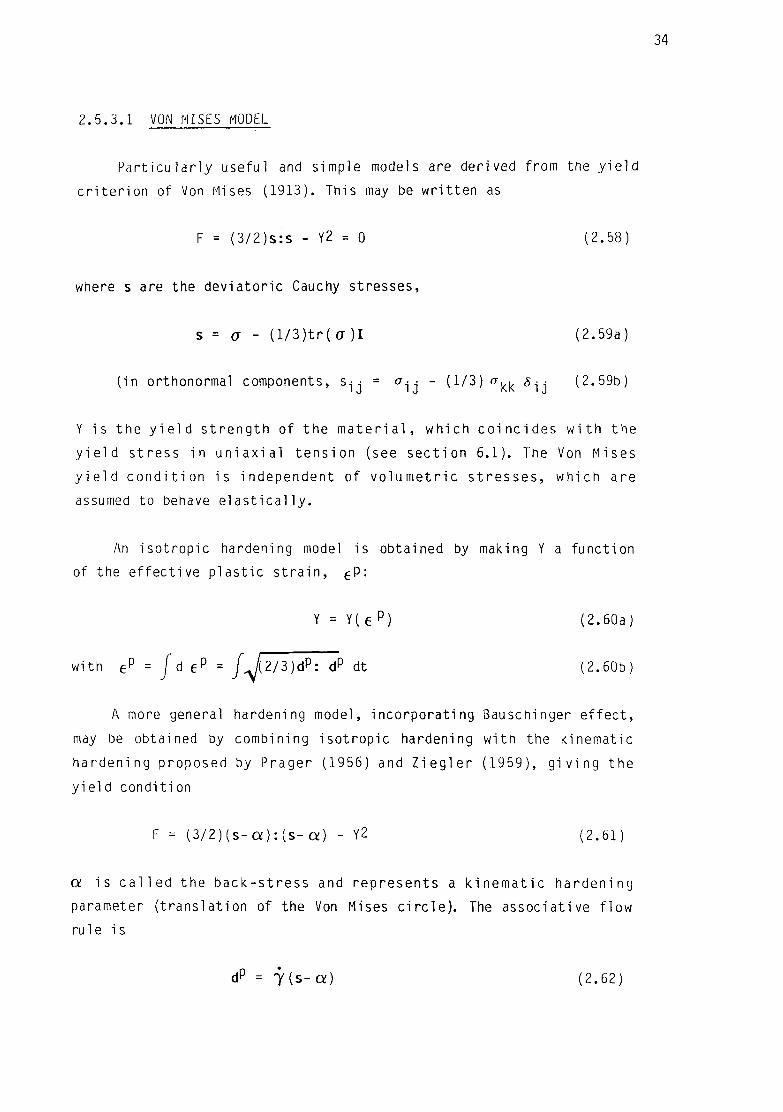
2.5.3.1 VON MISES MODEL
Par t i cu la r l y usefu] and simple models are derived from the y i e l d
c r i t e r i on of Von Mises (1913). This may be wr i t ten as
F = (3/2)s:s - Y2 = 0 (2.58)
where s are the deviatoric Cauchy stresses,
s = a - (l/3)tr(a)I (2.59a)
( in orthonormal components, s ^ = a^- - (1/3) o-^ 5 . . (2.59b)
Y is the y i e l d s t reng th of the m a t e r i a l , which co inc ides w i t h the
y i e l d s t ress in u n i a x i a l tens ion (see sec t ion 6.1). The Von Mises
y i e l d c o n d i t i o n is independent of vo lumet r i c s t r esses , which are
assumed to behave e l a s t i c a l l y .
An isotropic hardening model is obtained by making Y a funct ion
of the e f fec t ive p las t i c s t r a i n , e P:
Y = Y(e p ) (2.60a)
with eP = J 6 e p = J A 2/3) dp: dP dt (2.60b)
A more general hardening model, incorporat ing Bauschinger e f fec t ,
may be obtained by combining isot rop ic hardening wi th the kinematic
hardening proposed by Prager (1956) and Z i e g l e r (1959), g i v i ng the
y i e l d condit ion
F = ( 3 / 2 ) ( s - a ) : ( s - a ) - Y2 (2.61)
o: i s c a l l e d the back-s t ress and represents a k inemat ic hardening
parameter ( t rans la t ion of the Von Mises c i r c l e ) . The associat ive f low
ru 1 e is
dP = 7 ( s - a ) (2.62)

35
and the hardening laws,
a= (2/3)hadP (2.63a)
Y = hy eP (2.63b)
Imposing the cons is tency c o n d i t i o n (F = 0) dur ing l o a d i n g , and
combining eqns. (2.51), (2.53), (2.61)-(2.63), the s t r e s s - s t r a i n
re la t ion is found to be
a = c:Ld - ( s - a ) ( 3 / 2 ) d : ( s - a ) / Y 2 ( i + h ' / 3 G ) J (2.64)
where h' = hy+ na ( p l a s t i c modulus). Purely i s o t r o p i c hardening i s
obtained with h a =0, and purely kinematic with hY=o.
In a u n i a x i a l t e s t , law (2.64) w i l l p rov ide an E l a s t o p l a s t i c
hardening modulus of
h = 1/L1/E + 1/h'J (2.65)
where E - G(3 X+2G)/( X+G) (Young's modulus of elasticity).
2.5.3.2 OTHER PLASTICITY MODELS
P l a s t i c i t y in s o i l s i s gene ra l l y considerably more complicated
than the above Von Mises model. Pressure dependent y i e l d , anisotropy,
d i l a t a t i o n and n o n - a s s o c i a t i v i t y , hys te re t i c cyc l ic behaviour, pore
pressure, are impor tan t fea tu res f o r s o i l p l a s t i c i t y . An e x c e l l e n t
review of th is topic has been given by Marti and Cundall (1980).
The mathematical theory of p l a s t i c i t y i s a f i e l d s t i l l under
development. Very ref ined phenomenological models have been proposed
(e.g. Mroz (1967), Prevost (1978)). These models are based on
m u l t i p l e - s u r f a c e i d e a l i z a t i o n s . They provide elaborate s t ress-s t ra in
laws r e q u i r i n g cons iderab le c o m p u t a t i o n a l c o s t f o r n u m e r i c a l
mode l l i ng , thus in p r a c t i c e they are hard ly used. This f a c t has been
acknowledged by O r t i z and Popov (1983), who propose s i m p l e r , one-
surface models for metal p l a s t i c i t y .

36
F i n a l l y , a p r i n c i p l e t o be h e l d p resen t when c h o o s i n g a
p l a s t i c i t y mode l , i s t h a t i t can on l y be as r e l i a b l e and as
s o p h i s t i c a t e d as the e x p e r i m e n t a l i n f o r m a t i o n on wh ich the
determination of the model parameters is based. For example, there is
l i t t l e po in t in us ing anyth ing other than a Von Mises i s o t r o p i c
hardening model in a me ta l , i f a l l the i n f o r m a t i o n a v a i l a b l e i s a
uniaxial s t ress-s t ra in law. On the other hand, the added complicat ion
of some models may not be necessary i f the load ing is main ly
monotonic.
CHAPTER 3
NONLINEAR NUMERICAL MODELS FOR SOLID MECHANICS
3.1 INTRODUCTION
3.2 FINITE DIFFERENCE METHODS
3.3 FINITE ELEMENT METHODS
3.4 MESH DESCRIPTIONS
3.4.1 Lagrangian
3.4.2 Eulerian
3.4.3 Arbitrary Lagrangian-Eulerian
3.5 LARGE DISPLACEMENT FORMULATIONS
3.5.1 Total Lagrangian
3.5.2 Cauchy stress - velocity strain 3.5.3 Updated Lagrangian
3.6 TIME INTEGRATION
3.6.1 Central difference (explicit)
3.6.2 Trapezoidal rule (implicit)
3.6.3 Operator split methods
3.7 PRACTICAL CONSIDERATIONS FOR DISCRETE MESHES
3.7.1 "Locking up" for incompressible flow
3.7.2 "Hourg lass ing"
3.8 CONCLUSIONS

38
3.1 INTRODUCTION
The Governing equat ions in s o l i d mechanics are the equat ions of
mot ion, which can be w r i t t e n in component form as
a i j 5 j + p ( f i - i i i ) = 0 (3 .1)
where cr^j - j s the Cauchy s t ress t enso r , p the mass d e n s i t y , f-j are body
forces per u n i t mass ( t y p i c a l l y g r a v i t y ) , and u i d isp lacements . These
equat ions o r i g i n a t e f rom the balance of momentum p r i n c i p l e (sec t ion
2.4.2) . Th i s p r i n c i p l e may be s t a t e d a l t e r n a t i v e l y i n i n t e g r a l f o r m
(eqn. 2 .28 ) .
The p a r t i a l d i f f e r e n t i a l eqns. of m o t i o n (3.1) depend upon 3
space and 1 t i m e v a r i a b l e s . The n u m e r i c a l models d e s c r i b e d he re
per form independent s e m i d i s c r e t i z a t i o n s i n space and t i m e . F i r s t eqns.
(3.1) a re d i s c r e t i z e d i n space , y i e l d i n g a sys tem of o r d i n a r y
d i f f e r e n t i a l eqns. i n t i m e . These a re t hen i n t e g r a t e d w i t h a t i m e -
s tepp ing p rocedure .
The d i s c r e t i z a t i o n of the cont inuum may be achieved e i t h e r w i t h
F i n i t e E lement (FE) or F i n i t e D i f f e r e n c e (FD) methods . Both methods
have had s e p a r a t e h i s t o r i c a l d e v e l o p m e n t s , a l t h o u g h some degree of
c o n v e r g e n c e has been r e a c h e d l a t e l y i n t h e l i t e r a t u r e ( e . g .
B e l y t s c h k o , 1983). The t h e o r e t i c a l p r i n c i p l e s f o r bo th methods are
d i f f e r e n t : l oca l t r u n c a t i o n e r r o r s f o r FD, g lobal e r r o r norms f o r FE.
However, FE methods are a lso based on independent shape func t i ons f o r
each e l e m e n t . As a r e s u l t , FE and FD f o r m u l a t i o n s o f t e n produce
equ iva len t a l go r i t hms (e.g. Kunar and Minowa, 1981).
O ther n u m e r i c a l methods need o n l y a d i s c r e t i z a t i o n i n t h e
bounda ry : t h e Boundary E lement Methods (BEM). These were f i r s t
p roposed f o r s o l i d mechanics by R izzo (1967) and Cruse (1969) .
C o n s i d e r a b l e a d v a n t a g e can be g a i n e d by t h e r e d u c t i o n and
s i m p l i f i c a t i o n of the d i s c r e t i z a t i o n . For non l i nea r problems, however,
BEM lose much of t h e i r appeal. Volume i n t e g r a l s appear which requ i re
an a d d i t i o n a l d i s c r e t i z a t i o n of the cont inuum (e.g. Garc ia , 1981). For
t h i s reason BEM w i l l not be reviewed here.

39
Time i n t e g r a t i o n may be performed e i t h e r by modal ana lys is
methods or by d i r e c t i n t e g r a t i o n ( t ime-march ing) . Modal ana lys i s
requi res t r ans fo rma t i ons i n t o the frequency domain which are only
val id in a l inear regime, for which reason they must be ruled out for
nonlinear models. As to time-marching procedures two main a l ternat ives
e x i s t , e x p l i c i t or i m p l i c i t methods. Both have advantages and
disadvantages, which w i l l be reviewed b r i e f l y in th is chapter. Recent
a l te rnat ive procedures based on operator s p l i t t i n g methods w i l l also
be considered.
3.2 FINITE DIFFERENCE METHODS
F i n i t e D i f fe rence methods have been used f o r a long t ime by
engineers w i th in relaxat ion procedures (e.g. Southwell, 1940). F in i t e
D i f fe rence operators prov ide loca l approx imat ions f o r a system of
coupled d i f f e r e n t i a l equat ions. Due to t h i s f a c t , a one-step g lobal
solut ion is not possible and recourse must be made to relaxat ion and
i t e r a t i v e techniques. A d d i t i o n a l l y , FD methods have been assoc ia ted
norma l l y w i t h regu la r zoning (at l eas t t o p o l o g i c a l l y r e g u l a r ) . For
these two reasons, FD methods were eclipsed by the F in i te Element boom
in the 1960's for s t ruc tura l and so l id mechanics appl icat ions. FD has
always been popu lar , however, in other areas such as Eu le r ian f l u i d
mechanics (e.g. Nichols, H i r t , and Hotchkiss, 1980).
For a r e g u l a r mesh w i t h " I " and " J " l i n e s a l o n g the two
coordinate d i rec t ions , standard f i n i t e di f ference approximations for
the gradient of a vector u are given by:
u I + l / 2 , J + l / 2 a J _ ( u I + l , J + l / 2 _ u I , J + l / 2 )
u | : i / 2 , J + l / 2 = 1_ ( u I + l / 2 , J + l _ u j + l / 2 , J )
Ax.£
Eqns. (3.2) requ i re the mesh to be topo l o g i c a l l y
regular.
The use of contour integral formulas (Wi lk ins, 1964) allows the
appl icat ion of FD approximations to topo l ogi cal l y and g e o m e t r i c a l l y
i r regu lar meshes. The basic idea is to employ Gauss' theorem in order
(3.2)
and g e o m e t r i c a l l y

to express the g rad ien t of a f i e l d in a c e l l in terms of a contour
in tegra l . Considering ce l l VE enclosed by contour SE, and the gradient
of the displacement vector u,
J u i5JdV = [ u^jdS (3.3)
If the gradient is assumed constant in the cell, then
1 f ui ,j = - I u^jdS (3.4)
VEJSE
The contour integral may be evaluated assuming a l inear var ia t ion of u
along the edge of the c e l l .
Contour i n t e g r a l s may be used f o r any 2-0 polygon or 3-D
polyhedron, to i n t e r p o l a t e a value f o r the g rad ien t at the cen t re o
the c e l l , knowing the values at the corner nodes. For the p a r t i c u l a r
cases of t r i a n g l e s and t e t r a h e d r a , an a l t e r n a t i v e technique i s
avai lable (e.g. Mar t i , 1981), in which the gradients are interpolated
d i r e c t l y by i n v e r t i n g the s p a t i a l f i n i t e d i f f e r e n c e equat ions. This
technique has been fol lowed in the present work, and w i l l be detai led
i n sec t i on 4.2 .1 .
For e x p l i c i t time-marching models the semi-discrete equations of
motion become uncoupled. This means that only local approximations to
the p a r t i a l d i f f e r e n t i a l equat ions (3.1) are performed w i t h i n each
t i m e - s t e p , no i t e r a t i o n s being needed f o r a FD opera tor . Such a f a c t
was exploited in the development of the f i r s t FD "Hydrocodes" at the
U.S. na t iona l l a b o r a t o r i e s in the 1950's. These were o r i en ted main ly
towards sensit ive nuclear and defence appl icat ions. L i t t l e pub l i c i t y
was given u n t i l the 1960's (Wilkins (1964), Maenchen and Sack (1964),
Noh (1964)). At t h i s t ime F i n i t e Element Methods had j u s t been
in t roduced f o r s o l i d mechanics (Clough, 1960), and techniques were
being developed for l inear analysis. Not much at tent ion was given to
FD f o r s o l i d mechanics by the eng ineer ing community, as indeed FE
methods seemed much more powerful and indeed advantageous for l inear
systems, being able to provide a one-step global so lu t ion .
I n t e r e s t in the non l inear and wave-propagat ion regimes f o r
spec ia l i zed eng ineer ing a p p l i c a t i o n s in the l a t e 1960's and 1970's

41
created a resurgence of the Hydrocodes (Bertholf and Benzley (1968),
Wilkins (1975)), and a cer ta in degree of convergence between FD and FE
l i t e r a t u r e (Belytschko (1978), Kr ieg and Key (1976), Goudreau and
Hal lquist (1982)). Exp l i c i t f i n i t e - d i f f e r e n c e methods were popularized
to wider sectors of the eng ineer ing community, and new codes were
created such as PISCES (Hancock, 1976), the rock mechanics codes of
Cundall and Marti (1979), and PR3D for so l id mechanics impact by Marti
(1981).
3 .3 FINITE ELEMENT METHODS
The f i r s t appl icat ion of F in i te Element techniques for continua
was by Clough (196U), a l though the t h e o r e t i c a l bases f o r the method
had already been set by Courant (1943) and appl icat ions to s t ructura l
analysis had been proposed ear l i e r (Argyris and Kelsey, 1954).
F in i te Element d iscre t iza t ions rely on two essential ingredients:
a v a r i a t i o n a l or weak form of the eqns. of mot ion (3.1), and a
c o n s t r u c t i o n of approximate s o l u t i o n s based on genera l i zed nodal
coordinates and independent element shape funct ions.
The domain V i s subdiv ided i n t o elements VE, in te rconnec ted by
nodes. An approximate solut ion is constructed w i th in an element E as a
product of shape functions N^x) and the nodal displacements u f ( t ) :
u ( x , t ) = u ^ ( t ) N j ( x ) ( 3 . 5 )
where I is summed over the nodes of the element. The shape functions
are chosen so tha t u is cont inuous over the element boundar ies,
a l though i t s g rad ien t need not be cont inuous (CO c o n t i n u i t y ) . The
shape f unc t i ons Ni s o de f ined are independent of t i m e ; eqn. (3.5)
c o n s t i t u t e s i n f a c t a l o c a l s e p a r a t i o n o f v a r i a b l e s
(semi d isc re t i zat i on ).
The discrete form of the gradient operator may be wr i t ten as
u i ' j " B j l u i l (3.6)

42
where
BJi dxi
Let the s o l i d continuum be V w i t h boundary S, c o n s i s t i n g of Sy
and S j ' w h e r e
u = u* on Su
a n = T* o n sT
A weak form of the eqns. of motion (3.1) may be obta ined by us ing
e i ther Galerkin weighed residuals or the v i r t ua l work p r i nc ip l e , both
of which y ie ld the same resu l t :
f V i , j C T i j d V + r p v i u i d V = JpV i f i dV + [v-jT^dS (3.7)
V V V ST
where v is the test funct ion (or var ia t ion) and u the t r i a l func t ion .
Eqns. (3.7) requ i re only C° c o n t i n u i t y f o r both t r i a l and t e s t
f u n c t i o n s , as opposed to (3.1), f o r which Cl c o n t i n u i t y is needed. I f
the approximations defined in (3.5) are used for u and v, and because
(3.7) must hold f o r a r b i t r a r y v, the g lobal d i s c r e t e equat ions are
deduced:
Mu + P(u) = R (3.8)
where the global c o e f f i c i e n t mat r ices M, P, R are assembled from
indiv idual element matrices that take the form:
ME= / pNjNj&jjdV (mass matr ix;
VE
PE= / B j j ^ j d V ( internal forces) (3.9; J VE
RE= / f-j NjdV +f NIT idS (external forces)
v£ Js$

43
(3.8) is a system of ordinary d i f f e r e n t i a l equations of second order
in t i m e ; i n t e g r a t i o n of these is discussed in sec t i on 3.6. For a
l inear model (small deformations and e las t ic behaviour), (3.8) becomes
Mii + Ku = R (3.10)
The s t i f fness matrix K is assembled from element matrices of the type
KE = / 6 j j C i j k l B 1 K d V (3.11)
J vE
In s ta t ic analysis the i ne r t i a term may be dropped from eqns. (3 .8 ) :
P(u) = R (3.12)
which for the linear case becomes
Ku = R (3.13)
For l i n e a r a n a l y s i s , a s o l u t i o n is obta ined merely by i n v e r t i n g the
s t i f f n e s s ma t r i x K in eqns. (3.10) or (3.13). In a non l inear case,
eqns. (3.8) or (3.12) must be solved in a number of steps using Newton-
Raphson or i t e r a t i v e techniques. I t is in te res t ing to note the a b i l i t y
of FE to give a one-step s o l u t i o n to the l i n e a r problem, which F0
methods lack , having to approach the g lobal s o l u t i o n through
r e l a x a t i o n and i t e r a t i o n . Hence the p o p u l a r i t y of FE f o r l i n e a r
problems. For nonlinear behaviour, however, th i s advantage disappears'*
as both FE and FD have to perform some sort of i t e ra t i ons .
For large systems, the assemblage of matrix K is undesirable, as
core memory l i m i t s may be exceeded and recourse must be made to slow,
cost ly disk Input/Output. This fact accounts for the popular izat ion of
r e l a x a t i o n techniques f o r equa t i on s o l v i n g (e .g . F lanagan and
Belytschko, 1981a), which avoid the assemblage of global coe f f i c ien t
ma t r i ces . The FE operators are used only at a loca l l e v e l . In t h i s
case FE become conceptually very s im i la r to FD methods with general
topology, special ly as they o f ten prov ide equ iva len t a l go r i t hms f o r
the local approximations (Kunar and Minowa, 1981).

44
3.4 MESH DESCRIPTIONS
Let a p a r t i c l e X of body B be def ined by i t s p o s i t i o n at t=0
( re ference c o n f i g u r a t i o n ) , X . At t ime t ( cu r ren t c o n f i g u r a t i o n ) the
posi t ion of the pa r t i c le w i l l be
x = x(X, t ) (3 .14)
x are called the spatial coordinates, and X the material coordinates
of X. Eqns. (3.14) describe the motion of 8.
For the discretization of B three types of meshes may be used,
depending on the motion of the nodes of the mesh. The position of a
point of the mesh, initially coincident with particle X, will be given
by X = X(X,t).
3.4.1 LAGRANGIAN
In a lagrangian description the mesh follows the motion of the
body,
X(X,t) = x(X,t) (3.15)
A given node remains co i nc i den t w i t h the same ma te r i a l p a r t i c l e
throughout the motion. Each element w i l l contain the same domain of
material throughout the de fo rma t i on , thus en fo r c i ng i m p l i c i t l y the
cont inu i ty equation.
Motion of the boundary does not present d i f f i c u l t i e s , as i t
always co inc ides w i t h the mesh boundary. For a sca la r f i e l d g (X , t ) ,
the material t ime der ivat ive ( i .e. fo l low ing the pa r t i c l e ) coincides
wi th the par t ia l time der iva t ive :
dg g = - (3 .16)
dt
The only disadvantage of th is descr ipt ion comes from the fact that the
mesh can become excess ive ly d i s t o r t e d f o r c e r t a i n problems (e.g.
f l u i d s , high v e l o c i t y impact ) . In some cases, " rezon ing" techniques

45
may be used to circumvent this problem (e.g. Kalsi and Marti, 1985).
3.4.2 EULERIAN
In an Eulerian description the mesh is fixed in space, i.e.
X(X,t) = X (3.17)
Nodes are no longer coincident wi th material par t ic les through t ime,
and the material f lows through the c e l l s . Continuity must be enforced
e x p l i c i t l y . The ma te r i a l t ime d e r i v a t i v e of g (X> t ) inc ludes a f l u x
term:
69 39 dx dg d9 g = _ + = _ + _ v (3.18)
dt dx dt dt dx
Numerical computat ions f o r the f l u x of sca la r f i e l d s tend to smear
t he i r values, which w i l l not be defined as sharply as for a Lagrangian
mesh. Ma te r i a l boundaries are d i f f i c u l t to desc r i be , as they move
re la t i ve to the mesh. On the c red i t side, d i s t o r t i on is not a problem,
making Eulerian meshes preferrable to Lagrangian meshes for very large
deformations.
3.4 .3 ARBITRARY LAGRANGIAN-EULERIAN
A r b i t r a r y Lagrang ian-Eu le r ian (ALE) d e s c r i p t i o n s at tempt to
combine the advantages of Lagrangian and Eu le r ian meshes. The mesh
moves w i t h an a r b i t r a r i l y def ined mot ion , X ( X , t ) . d X / d t = 0 f o r an
Eulerian mesh, dX/dt=v for a Lagrangian mesh. X can be defined so as
to fo l low the material in the boundary, but without causing excessive
d i s t o r t i o n in the i n t e r i o r . ALE f o r m u l a t i o n s have been developed by
Noh (1964) and H i r t et a l . (1974) in FO f o r m a t s , and by Donea et a l .
(1977) and Belytschko and Kennedy (1978) in FE.
Material der ivat ives are given by
d9 dx 59 g = _ + (3.19)
dt dt dx

46
With an ALE d e s c r i p t i o n p rope r t i es s t i l l need to be f l uxed through
c e l l s , and some smearing may occur as a resu l t .
A c r u c i a l aspect in ALE d e s c r i p t i o n s is the d e f i n i t i o n of the
a r b i t r a r y motion of the mesh X f o r i n t e r n a l po in t s . General ly a
complex rezoning algor i thm is necessary for opt imizing the new mesh
p o s i t i o n s at each s tep. Such a general rezoning a l g o r i t h m has been
proposed f o r 2-D by G i u l i a n i (1982). Schreurs (1983) has proposed a
mesh o p t i m i z i n g a l g o r i t h m based on the de format ion of a f i c t i t i o u s
ma te r i a l from an " i d e a l " mesh. In f a c t ALE techniques would be
equivalent to Lagrangian descript ions in which rezoning is performed
at every s tep. Some a p p l i c a t i o n s (e.g. metal fo rm ing) may not need
such f requent rezon ing , and Lagrangian techniques w i t h rezoning at
wider in terva ls could be preferrable.
3.5 LARGE DISPLACEMENT FORMULATIONS
Severa l f o r m u l a t i o n s are p o s s i b l e depend ing on wh ich
c o n f i g u r a t i o n s the s t ress and deformat ion tensors are r e f e r r e d t o .
Three a l ternat ives widely used in so l id mechanics are presented below.
3.5.1 TOTAL LAGRANGIAN
The 2nd P i o l a - K i r c h h o f f s t ress tensor S and the Green s t r a i n
tensor E, both of which r e l a t e to the re ference c o n f i g u r a t i o n , are
used to descr ibe the mate r ia l behaviour. H i b b i t , Marcal and Rice
(1970) proposed th i s descr ipt ion in the f i r s t published la rge -s t ra in ,
large-displacement nonlinear formulat ion for general purpose FE codes.
A cons t i tu t i ve re la t ion is given by
S = S(E) (3.20)

47
and in rate form by
S = D:E (3.21)
(S IJ = DIJKLEKL components)
S and E being ma te r i a l t enso rs , t h e i r ma te r i a l rates are o b j e c t i v e .
This formulat ion is advantageous f o r Hypere las t i c m a t e r i a l s , whose
behaviour is described on the reference conf igurat ion. In th is case,
ca l l i ng W the s t ra in energy funct ional per un i t mass,
d2W
dE2 (3.22)
aw s = —
d£
E l a s t i c - p i a s t i c ma te r i a l behaviour is best descr ibed on the
cu r ren t c o n f i g u r a t i o n , x ( H i l l , 1950). I t i s poss ib le to t r ans fo rm
such a law i n t o one of the type (3.21) (e.g. H i b b i t et a l . (1970),
Kr ieg and Key (1976)), but complex and compu ta t i ona l l y expensive
transformations are necessary. However, Simo and Ort iz (1985) suggest
that to ta l Lagrangian, Hyperelastic-type formulat ions provide a more
r igorous approach f o r i n c r e m e n t a l , n o n - l i n e a r c a l c u l a t i o n s . Such
r i gour is not j u s t i f i e d in e x p l i c i t c a l c u l a t i o n s w i t h very smal l
steps.
3.5.2 CAUCHY STRESS-VELOCITY STRAIN
A descript ion based on the current conf igurat ion may be used to
model the behaviour of materials wi th smooth memory. In the simplest
case, the Jaumann ra te of Cauchy s t ress ( a ) and the ra te of
deformation tensor (veloc i ty s t r a i n , d) are related by
ff= C:d (3.23)
( ajj = C j ^ i d k i in component form)

48
where C is the c o n s t i t u t i v e tensor . For an e l a s t i c - p l a s t i c mate r ia '
(hypoelastic with associated p l a s t i c i t y ) C takes the form
C i j k l = ^ i j 5 k i + 2G(5 i k5J 1 - ^ i j n k i ) (3.24)
where rj >0 for p las t ic loading, =0 otherwise
n is the un i t normal to the y i e l d surface
The Jaumann d e r i v a t i v e used i n eqn. (3.23) p r o v i d e s t h e
cons t i tu t i ve part of the stress rate. To obtain the to ta l stress rate
the ro tat ional components must be added:
a• • = o- • + w• n • + w- a • 1J 1J W1PCTPJ WJP pi (3 .25)
I f the mate r ia l behaviour is a n i s o t r o p i c , C must be updated w i t h a
s imi lar object ive rate:
c i j k l _ c i j k l + w i p c p j k l + w j p c i p k l + w k p c i j p l + w l p c i j k p (3.26)
An a l te rna t ive formulat ion results from the use of the Truesdell
rate in eqn. (3.23):
(J= C:d :3.27
(3.23) and (3.27) are equivalent i f one sets
C i j k l = C i j k l + CTij5kl-^ik5jl+oril5jk+(7jk5il + CTil5ik)/2 ( 3 - 2 8 )
The Truesdel l s t ress ra te is the fo rward P io la t r a n s f o r m a t i o n
(eqns. 2.22, 2.25) of the ra te of the 2nd P i o l a - K i r c h h o f f s t ress
tensor:
O = 0 t * ( J - 1 S ) [3.29)
Pinsky, Ort iz and Pister (1983) have suggested that the Truesdell
r a t e f o r m u l a t i o n i s t h e n a t u r a l one t o use ( i n t h e c u r r e n t
c o n f i g u r a t i o n ) f o r h y p e r e l a s t i c i t y . In t h i s case the c o n s t i t u t i v e
tensor is obtained d i r e c t l y , from the to ta l Lagrangian tensor D, as

49
£ = 0 t * ( j - l D ) .
C lass i ca l p l a s t i c i t y is descr ibed on the current conf igurat ion
( H i l l , 1950). Jaumann Cauchy stress formulat ions have been widely and
success fu l l y used f o r e l a s t i c - p l a s t i c behaviour (Wi l k ins (1964),
Maenchen and Sack (1964) , K r i e g and Key (1976) ) . W i th such
f o r m u l a t i o n s h y p e r e l a s t i c b e h a v i o u r ( r e l a t e d to the o r i g i n a l
conf igurat ion) may also be described, a lbe i t in a less convenient way,
as the c o n s t i t u t i v e r e l a t i o n s need to be pushed fo rward i n t o the
current conf igura t ion .
F i n a l l y , one problem w i t h t h i s f o r m u l a t i o n is t ha t d is not
i n t e g r a b l e ( i . e . i t i s not the ra te of any v a l i d s t r a i n t enso r ) .
Additional s t ra in computations must be done i f a to ta l s t ra in measure
is requi red.
3.5.3 UPDATED LAGRANGIAN
In t h i s f o r m u l a t i o n the model is descr ibed on a reference
conf igurat ion, which is updated at each increment to coincide wi th the
cu r ren t c o n f i g u r a t i o n . From t h i s updated reference, the incremental
conf igurat ion is described wi th a t o ta l Lagrangian formulat ion. This
method was f i r s t proposed by Yaghmai and Popov (1971), and has been
wide ly used since f o r incrementa l non l inear a n a l y s i s : Osias and
Swedlow (1974), Bathe et a l . (1975), Nagtegaal and de Jong (1981).
For t h i s d e s c r i p t i o n , F = I ( i d e n t i t y ) and J = 1. Hence, eqn.
(3.29) imp l i es S = a. I t i s a lso easy to see from eqn. (2.19) t ha t E =
d. In f a c t t h i s f o r m u l a t i o n reve r t s to the Truesde l l Cauchy s t ress
ra te f o r m u l a t i o n , eqn. (3.27). This means t ha t the tensor to be used
for the tangential s t i f fness is £.
3.6 TIME INTEGRATION
Using e i ther F in i te Difference or F in i te Element Methods for the
spat ial semid iscre t iza t ion, the par t ia l d i f f e r e n t i a l eqns. of motion
(3.1) may be t rans formed i n t o a system of o rd ina ry d i f f e r e n t i a l

50
equations in t ime:
Mii + Cu + P(u) = R (3.30)
These eqns. can be solved e i t h e r by modal ana l ys i s or by d i r e c t
i n t e g r a t i o n . Modal ana lys is methods (e.g. Bathe and Wilson (1976),
chpt . 8) per form t r a n s f o r m a t i o n s of eqns. (3.30) which are only
va l id for l inear or quasi - l inear systems ( i .e. P(u) = Ku)
For non l inear a n a l y s i s , d i r e c t i n t e g r a t i o n ( t ime-march ing)
methods must be used. For these the t ime domain is divided into t ime-
steps {At), and an incremental analysis is performed for each step.
Time integrat ion procedures may be c l ass i f i ed in to e x p l i c i t and
i m p l i c i t . Exp l i c i t schemes compute the incremental displacements u
from the e q u i l i b r i u m cond i t i ons at t ime t . I m p l i c i t schemes, on the
c o n t r a r y , solve the eqns. of motion (3.30) at t+hAt > t , producing an
i m p l i c i t system of eqns. for ut+At.
Two of the most common and rep resen ta t i ve t i m e - i n t e g r a t i o n
schemes, one in e i ther c lass, are presented below.
3.6.1 CENTRAL DIFFERENCE (EXPLICIT)
Central d i f f e r e n c e methods are the most w ide ly used e x p l i c i t
schemes for so l id mechanics, being the optimal from a very wide class
(Key, 1978). The F in i te Difference expressions used for ve loc i ty and
acceleration are
a n + l / 2 = ( l / i+ l_ j i ) M t ( 3 > 3 1 a )
iin = ( u n + 1 / 2 - u n " 1 / 2 ) / A t (3.31b)
Note t h a t each d e r i v a t i v e lags the value by ha l f a t i m e - s t e p .
Par t i cu la r iz ing the equations of motion (3.30) at time n,
Mun + Cun + P(un) = Rn (3.32)

51
Using eqn. (3.31b) and l e t t i n g On = ( u n - l / 2 + u n + l / 2 ) / 2 , eqn. (3.32) may
be s o l v e d , y i e l d i n g :
u " + l / 2 = (MMt-C/2)-1[MMt-C/2)un - 1 / 2+Rn-P(un)] (3.33)
The new d i s p l a c e m e n t s un + 1 are t hen found f r o m eqn. (3 .31a) . I f t h e
system has no damping (C = 0) and the mass m a t r i x M i s d i agona l , eqns.
(3.33) become uncoupled:
•n+l/2= - n - l / 2 + M - l [ R n _ p ( u % t (3.34)
These eqns. can t h e n be s o l v e d i n d e p e n d e n t l y f o r each degree of
freedom I :
• n + l / 2 = G n - l / 2 + A ( R n _ p n ) / l t ) i ( 3 > 3 5 )
The equat ions a lso become uncoupled i f the damping i s assumed t o
be of the Rayleigh t ype , as shown in sec t i on 4.6.
This uncoup l ing of the equat ions of motion i s the major advantage
of e x p l i c i t i n t e g r a t i o n procedures. No mass or s t i f f n e s s mat r i ces need
be i n v e r t e d or even assembled, as a l l the incrementa l c a l c u l a t i o n s f o r
each degree of freedom can be done independent ly at the loca l l e v e l .
This not only a l l ows f o r a s imp le r a r c h i t e c t u r e in computer codes, but
i t enab les t h e t r e a t m e n t of n o n - l i n e a r i t i e s (be i t o f C o n s t i t u t i v e ,
Geomet r i c or Boundary t y p e ) w i t h v i r t u a l l y no added c o s t f r o m t h e
l i n e a r case . The number o f o p e r a t i o n s per t i m e - s t e p i s much s m a l l e r
than f o r i m p l i c i t methods ( s e c t i o n 3 .6 .2 ) , and s t o r a g e r e q u i r e m e n t s
grow only l i n e a r l y w i t h the s ize of the problem.
The main d i s a d v a n t a g e of t h e c e n t r a l d i f f e r e n c e and o t h e r
e x p l i c i t methods i s t h a t computa t ions a re o n l y c o n d i t i o n a l l y s t a b l e
depending on the t i m e - s t e p s i ze . The t i m e - s t e p must be sma l l e r than a
c e r t a i n c r i t i c a l v a l u e f o r n u m e r i c a l e r r o r s no t t o grow unbounded.
Th i s c o n s t i t u t e s a ma jo r o b s t a c l e f o r c e r t a i n p rob l ems where an
excessive number of t ime-s teps makes the ana l ys i s too c o s t l y .
The s t a b i l i t y of the c e n t r a l d i f f e r e n c e method i s considered in
s e c t i o n 4.7. The t i m e - s t e p i s l i m i t e d by t h e Couran t c r i t e r i o n , i . e .

52
the time i t takes the stress waves to t ravel across one element. This
l i m i t a t i o n is consistent wi th the l oca l , uncoupled in tegrat ion of the
equat ions of mot ion. I f the t i m e - s t e p was l a rge r than the Courant
c r i t i c a l value, stress waves would t ravel across an element w i th in one
t i m e - s t e p , a f f e c t i n g the surrounding e lements. The incrementa l
behaviour of that element would no longer be independent from the rest
of the model.
Centra l d i f f e r e n c e schemes have been w ide l y used in non l inear
numerical codes, from the ea r l y FD hydrocodes of Wi1kins(1964) and
Maenchen and Sack(1964), to the FE codes of Hal lquist (1982a, 1982c),
Key (1974), and Belytschko and Tsay(1982). The accuracy and
s t a b i l i t y of central di f ference methods has been studied and discussed
by var ious authors (e.g. Be ly tschko, Holmes and Mul len (1975),
Belytschko(1978), Krieg and Key(1973)). The central di f ference method
is considered as the most convenient w i th in the e x p l i c i t class.
3.6.2. TRAPEZOIDAL RULE (IMPLICIT)
The s o - c a l l e d t r apezo ida l ru le i s an example of i m p l i c i t
in tegrat ion methods. In fact i t const i tutes a par t i cu la r case of the
Newmark fami ly , probably the most popular of the i m p l i c i t schemes. A
constant average a c c e l e r a t i o n is assumed f o r each increment At. The
difference equations are:
u n + h = ( i in + u n + 1 )/2 (0 s< h < 1)
u n + 1 = un+ ( i in + i i n + 1 )At/Z (3.36) u n+l = u n + a n 4 t + ( .jjn + yn+1 ) A t 2 / 4
For obtaining un+l the equations of motion are enforced for time
t+At. In an undamped case,
Miin+1+ P(un + 1) = Rn+1 (3.37)
Eqn. (3.37) i s an i m p l i c i t r e l a t i o n f o r u n + l . S u b s t i t u t i n g the
d i f f e r e n c e expressions (3.36) in (3.37) the f o l l o w i n g system is
obtained:

53
L ( 4 M t 2 ) M + K n + 1 j u n + 1 = Rn + 1 + M [ 4 M t 2 ) u n + ( 4 M t ) u n + i i n J (3.38)
where Kn+1 i s the secant s t i f f n e s s ma t r i x ( pn+l= Kn+lun+1).
For a l i n e a r system (Kn = cons tan t ) eqns. (3.38) may be solved by
i n v e r t i n g t h e m o d i f i e d s t i f f n e s s m a t r i x K*, d e f i n e d as
K* = ( 4 / 4 t ^ M + K n + 1 (3.39)
For n o n l i n e a r sys tems t h e e q u a t i o n s a re g e n e r a l l y s o l v e d by
d i r e c t e l i m i n a t i o n techn iques , e.g. Newton-Raphson type methods (which
requ i re t r i a n g u l a r i z a t i o n of K*).
The t r a p e z o i d a l r u l e i s u n c o n d i t i o n a l l y s t a b l e (see e.g.
Belytschko and Schoeberle, 1975), the t i m e - s t e p being l i m i t e d only by
accuracy c o n s i d e r a t i o n s . Th i s i s t h e main advan tage of i m p l i c i t
schemes, which makes them more appropr ia te f o r problems in which la rge
t ime-s teps can be used. I f the t ime -s teps are l i m i t e d to smal l values
f o r reasons other than s t a b i l i t y (e.g. steep n o n l i n e a r i t i e s , accuracy,
s t ress-waves) i m p l i c i t methods lose t h e i r advantage.
Another l i m i t a t i o n i s the la rge s torage requ i red f o r the m a t r i x
c o e f f i c i e n t s , which r e s t r i c t s severe ly the s ize of problem tha t can be
s o l v e d i n - c o r e . L a r g e r models and 3-D a n a l y s e s must o f t e n r e s o r t t o
o u t - o f - c o r e storage w i t h f requent and slow disk I/O. Because of t h i s
problem, a l t e r n a t i v e equat ion s o l v i n g methods based on i t e r a t i v e or
r e l a x a t i o n procedures are becoming popular . C lass i ca l methods of t h i s
t y p e are t h e Jacob i and Gauss -Se ide l p r o c e d u r e s , a l t h o u g h t h e i r
e f f ec t i veness f o r f i n i t e Element codes i s l i m i t e d (Be ly tschko, 1983).
More p r o m i s i n g f o r FE t o p o l o g i e s are c o n j u g a t e g r a d i e n t and q u a s i -
Newton methods. A new and seduct ive Element-by-Element equat ion so lve r
has been proposed l a t e l y by Hughes, L e v i t and Winget (1983b) ;
b a s i c a l l y i t c o n s i s t s of an o p e r a t o r - s p l i t t i n g method t h a t t akes
advantage of the FE data s t r u c t u r e (see a l s o s e c t . 3 .6 .3) .
I m p l i c i t methods are l e s s r e l i a b l e as t o c o m p l e t i n g t h e
c o m p u t a t i o n s w i t h o u t c r a s h i n g and w i t h t h e r e q u i s i t e a c c u r a c y t han
e x p l i c i t methods (Be ly tschko , 1983).

54
N o n l i n e a r models are g e n e r a l l y more d i f f i c u l t w i t h i m p l i c i t
schemes. F i r s t l y l i e s t h e i n c r e a s e d c o s t of t h e Newton-Raphson
i t e r a t i o n s . Then i s t h e f a c t t h a t a l l b o u n d a r y c o n d i t i o n s ,
n o n l i n e a r i t i e s , e t c . must be i n c l u d e d i m p l i c i t l y i n t h e secan t
s t i f f n e s s m a t r i x (K* i n eqn. ( 3 .39 ) ) . Th i s g r e a t l y c o m p l i c a t e s t h e
f o r m u l a t i o n and may r e s t r i c t t h e range o f c o n s t i t u t i v e models and
boundary c o n d i t i o n s t h a t may be used.
3 .6 .3 OPERATOR SPLIT METHODS
From the d iscuss ion in sec t ions 3.6.1 and 3.6.2, i t i s c l ea r t h a t
an operator combining the advantages o f e x p l i c i t methods (uncoup led
equat ions , s imple program a r c h i t e c t u r e , no s torage of g loba l m a t r i x )
w i t h t h e u n c o n d i t i o n a l s t a b i l i t y of i m p l i c i t methods w o u l d be ve ry
d e s i r a b l e . O p e r a t o r s p l i t m e t h o d s a t t e m p t t o c o m b i n e such
c h a r a c t e r i s t i c s .
An u n c o n d i t i o n a l l y s t a b l e e x p l i c i t p r o c e d u r e was p roposed by
T r u j i l l o (1972) and r e c e i v e d v a r i o u s e x t e n s i o n s by Park (1982) . T h i s
c o n s i s t s i n s p l i t t i n g t h e s t i f f n e s s K i n t o upper and l o w e r m a t r i c e s
and p e r f o r m i n g t w o passes i n a l t e r n a t e d i r e c t i o n s , each pass
corresponding to h a l f a t i m e - s t e p . Al though t h i s procedure appears to
work w e l l f o r heat c o n d u c t i o n ( T r u j i l l o , 1975) , f o r s t r u c t u r a l
dynamics the accuracy i s poor (Mul len and Be ly tschko , 1983).
A p r o m i s i n g avenue i s t h e use o f E l e m e n t - b y - E l e m e n t me thods ,
w h i c h p e r f o r m a f a c t o r i z a t i o n t a k i n g advan tage of t h e FE da ta
s t r u c t u r e . Such an a l g o r i t h m has been p roposed f o r s o l i d and
s t r u c t u r a l mechanics by O r t i z , P insky and T a y l o r (1983) . In i t s
o r i g i n a l f o r m t h i s method was p roposed by Hughes, L e v i t and Winget
( 1 9 8 3 a ) f o r h e a t c o n d u c t i o n . The same a u t h o r s (1983b) r e p o r t
u n s a t i s f a c t o r y accu racy i n s t r u c t u r a l d y n a m i c s , and sugges t t h i s
t e c h n i q u e be used i n s t e a d as a l i n e a r e q u a t i o n s o l v e r w i t h i n an
i m p l i c i t scheme. The approach of O r t i z e t a l (1983) uses v e l o c i t i e s
and s t r e s s e s as unknowns. They p e r f o r m t w o passes i n a l t e r n a t i n g
d i r e c t i o n s w i t h i n a t r apezo ida l r u l e to ob ta in second order accuracy.
A quest ion mark s t i l l hangs over the accuracy of these methods.

55
3.7 PRACTICAL CONSIDERATIONS FOR DISCRETE MESHES
A number of undes i rab le e f f e c t s can be generated by the nature of
the s p a t i a l s e m i d i s c r e t i z a t i o n . Unacceptable s o l u t i o n s may be produced
by F i n i t e E lement meshes even i f t h e e l e m e n t s s a t i s f y t h e s t a n d a r d
convergence c r i t e r i a (e .g . Zi enk i e w i c z , 1977, c h p t s . Z&3). Two
p r o b l e m s , r e l a t e d t o t h e degree of v o l u m e t r i c c o n s t r a i n t , a re
discussed below. "Locking up" o c c u r s f o r e x c e s s i v e c o n s t r a i n t . w h i 1 e
"hourg lass ing" modes appear i f v o l u m e t r i c c o n s t r a i n t s are too re laxed .
Ano the r p r o b l e m no t d i s c u s s e d h e r e , bu t t o w h i c h r e f e r e n c e i s
made i n o t h e r s e c t i o n s (4 .2 .3 , 7.4.4) i s t h e e x c e s s i v e d i s t o r t i o n i n
Lagrangian meshes f o r models w i t h very l a rge de fo rma t i ons , which may
cause t a n g l i n g over of the mesh.
3 .7 .1 "LOCKING-UP" FOR INCOMPRESSIBLE FLOW
Some meshes ( i n p a r t i c u l a r c o n s t a n t s t r a i n t r i a n g l e s and
t e t r ahed ra ) g ive o v e r s t i f f s o l u t i o n s f o r i ncompress ib le p l a s t i c f l o w .
Al though t h i s i s a we l l known f a c t , some authors have cont inued to use
them f o r c o n v e n i e n c e (e .g . Johnson , 1976, 1977) . The v a l i d i t y o f
such p r a c t i c e has been s t r o n g l y q u e s t i o n e d ( H a l l q u i s t , Werne and
W i l k i n s , 1977).
The reason f o r " l o c k i n g - u p " was shown i n a c l a s s i c a l paper by
N a g t e g a a l , Parks and R ice (1974) t o be an e x c e s s i v e number of
v o l u m e t r i c i n c o m p r e s s i b i 1 i t y c o n s t r a i n t s i n t h e d i s c r e t e meshes.
According t o Nagtegaal , the number of vo l ume t r i c c o n s t r a i n t s must not
exceed t h e number o f Degrees Of Freedom (DOF) o f t h e mode l . I d e a l l y
the degree of c o n s t r a i n t should be the same as i n the cont inuum, w i t h
one incompressi bi 1 i t y equat ion per ma te r i a l po in t (v^ -j=(j). Thus the
idea l r a t i o DOF/const ra in ts equals 2 f o r plane s t r a i n or ax isymmetr ic
a n a l y s e s , and 3 f o r t h r e e - d i m e n s i o n a l mode l s . For c o n v e r g e n c e , t he
r a t i o DOF/const ra in ts should tend to a value g rea te r than 1 when the
mesh i s i n f i n i t e l y r e f i n e d . Nagtegaa l e t al (1974) s t u d i e d a few
commonly used elements and found some of them to be u n s u i t a b l e . Some
of t h e i r r e s u l t s are presented in t a b l e 3.1.

56
PLANE STRAIN
Constant S t r a i n T r i ang le
(CST) I T j - • n
i soparamet r ic 4-node '
q u a d r i l a t e r a l j Mixed Tr iang les-Quad.
(MTQ.MTQC)
A
/
t
y •
AXISYMMETRIC
Constant S t r a i n T r i ang le A
(CST) (exact hoop s t r a i n )
Constant S t r a i n T r i ang le A
(CST) (reduced hoop s t r . ) *•—*
Mixed Tr iang les-Quad.
(MTQ.MTQC) w i t h reducec j
hoop s t r a i n s -~
3-DIMENSIONAL
Constant S t r a i n T e t r a h .
(CST),5 per b r i c k ,
regular l a t t i c e
Constant S t r a i n T e t r a h .
(CST),6 per b r i c k ,
regu la r l a t t i c e
8-node isoparametr ic '
b r i c k
Mixed T e t r a h . - B r i c k
(MTB.MTBC)
5 or 6 T e t r a h . / B r i c k t
A A
. _» " C 3
t 1 I »-
1-" - ^
' / i V
' ' 1
Cons t ra in t s Element
1
3
1
3
1
1
1
1
7
1
Nodes Element
1/2
1
1
1/2
1/2
1
1/5
1/6
1
1
DOF Constra i nt
1
2/3
2
1/3
1
2
3/5
3/6
3/7
3
Table 3 . 1 : R a t i o s o f D e g r e e s o f F reedom t o i n c o m p r e s s i b i l i t y
c o n s t r a i n t s , f o r i n f i n i t e l y r e f i n e d 2 and 3-D meshes.

57
To achieve convergence, the number of volumetric constraints must
be re laxed. For t h i s , Nagtegaal et al (1974) proposed a mod i f i ed
var iat ional method which essent ia l ly consists of performing a reduced
i n t e g r a t i o n on the vo lume t r i c s t resses . This can be app l ied only to
elements in which f u l l numerical in tegrat ion comprises more than one
quadrature point. A one-point volumetric in tegrat ion is proposed for
4-node q u a d r i l a t e r a l s and 8-node b r i c k s . This method is c a l l e d
"select ive" in tegra t ion , and the elements produced possess the desired
number of constra ints . In prac t ice , reduced in tegrat ion is
o f ten extended f o r convenience t o t he d e v i a t o r i c s t r e s s e s as
wel 1 (Hal 1 quist,1982b). This excessive relaxat ion may create addit ional
problems ("Hourglassing") which must be treated appropriately (section
3.7.2). In a F i n i t e D i f f e rence contex t the equ iva len t to one-po in t
reduced i n t e g r a t i o n i s obta ined by us ing contour i n t e g r a l formulae
( W i l k i n s , 1964).
An a l te rnat ive so lu t ion , s ta r t ing of f from the simplest t r iang les
and tetrahedra, is to group several elements together and average the
vo lume t r i c s t r a i n s between them. Such a s o l u t i o n is the "Mixed
D iscre t iza t ion" (MD) procedure proposed by Mar t i and Cundall (1982).
This refers the deviator ic stra ins to the basic t r iangles/ te t rahedra
and averages the vo lume t r i c components w i t h i n one q u a d r i l a t e r a l (2
t r i a n g l e s ) or one b r i c k (5/6 t e t r ahed ra ) (sec t ion 4.2.2). This
technique has been employed for the present work. The resul t of th i s
MD may be interpreted as new, larger elements, which w i l l be termed in
the f o l l o w i n g MTQ (Mixed T r i a n g l e s - Q u a d r i l a t e r a l ) and MTB (Mixed
T e t r a h e d r a - S r i c k ) . These e lemen ts have the des i red number of
constraints ( tab le 3.1).
Johnson (1981) has also used a volumetric averaging procedure for
3-D s im i l a r to the proposed MD. For 2-D Johnson (1981) employs meshes
of crossed t r iang les , which were shown by Nagtegaal et al (1974) to be
less s t i f f than o rd inary t r i a n g l e l ayou ts . The behaviour of these
crossed layouts is not as good as tha t of MD, however (see sec t ion
5.7).

58
3.7 .2 "HOURGLASSING"
Some commonly used meshes a d m i t c e r t a i n unopposed de fo rmat ion
modes. These are c a l l e d "zero-energy" or "hou rg lass ing " modes, because
of t h e s i m i l i t u d e w i t h an h o u r g l a s s p a t t e r n . I f not d e a l t w i t h ,
hourg lass ing modes q u i c k l y grow and dominate the s o l u t i o n . Examples of
such meshes are q u a d r i l a t e r a l s or b r i c k s , w i t h one-po in t quadrature in
FE, or c o n t o u r i n t e g r a l f o r m u l a e i n FO. In bo th cases H o u r g l a s s i n g
appears as t h e p r i c e f o r an e x c e s s i v e r e d u c t i o n i n t h e s t r e s s
i n t e g r a t i o n . However, an t i -hourg l a s s i n g t r e a t m e n t s do e x i s t and may
s o m e t i m e s be p r e f e r r a b l e t o t h e e x c e s s i v e c o s t of s e l e c t i v e
i n t e g r a t i o n (Goudreau and H a l l q u i s t , 1982).
The f i r s t a n t i - h o u r g l a s s i n g s o l u t i o n s were r e p o r t e d i n t h e FO
hydrocodes (Maenchen and Sack, 1964) , c o n s i s t i n g o f a r t i f i c i a l
v i s c o s i t y te rms. A s i m i l a r procedure in 3-D has been used by W i l k i n s
e t a l . (1975) . These t e c h n i q u e s i n v o l v e c o n s i d e r a b l e c o m p u t a t i o n and
are no t c o m p l e t e l y i ndependen t o f r i g i d body modes. A more r i g o r o u s
t rea tmen t of hourg lass ing has been f o l l o w e d by Flanagan and Bely tschko
(1981b) , who pursue t h e i dea o f t h e o r t h o g o n a l i t y of h o u r g l a s s i n g
modes to the f i r s t - o r d e r modes, f i r s t proposed by K o s l o f f and F raz ie r
(1978). Flanagan and Bely tschko use an a d d i t i o n a l c o n t r i b u t i o n to the
s t i f f n e s s m a t r i x , c a l l e d s t a b i l i z a t i o n m a t r i x .
From a more p r a c t i c a l v i e w p o i n t Goudreau and H a l l q u i s t (1982)
have c o n s i d e r e d F lanagan and B e l y t s c h k o ' s a l g o r i t h m s t o i n v o l v e an
e x c e s s i v e c o m p u t a t i o n a l c o s t . F u r t h e r m o r e , exac t t r e a t m e n t of
hourg lass ing i s not necessary, as hourg lass ing modes are g lobal modes,
and element hourg lass ing i s o f ten a s tab le k inemat i c component of a
g lobal energy mode. In the DYNA codes H a l l q u i s t (1982b) uses an a n t i -
h o u r g l a s s i n g v i s c o s i t y based on F l a n a g a n ' s o r t h o g o n a l modes,
s i m p l i f i e d t o produce an opera t ion count 4 t o 5 t imes lower .
Reduced s e l e c t i v e i n t e g r a t i o n or "M ixed D i s c r e t i z a t i o n " r e s i s t
t he h o u r g l a s s i n g modes " n a t u r a l l y " w i t h d e v i a t o r i c s t r e s s e s , b y
passing the need f o r any spec ia l t r e a t m e n t . A quest ion mark i s put by
Goudreau and H a l l q u i s t (1982) on w h e t h e r t h e added c o s t o f t hese
techniques i s w o r t h w h i l e in terms of improved accuracy. A d d i t i o n a l l y ,
f o r some a p p l i c a t i o n s l i k e h igh-p ressure shock waves where s t reng th i s

59
not a f a c t o r , d e v i a t o r i c s t resses may not be able to r e s t r a i n
hourglassing.
3.8 CONCLUSIONS
Fin i te Difference and F in i te Element methods provide a l te rnat ive
solut ions for spat ia l semid iscre t iza t ion, w i th t he i r own independent
schools and l i t e r a t u r e . However, recent t rends in F i n i t e Elements
avoid the assemblage of g lobal c o e f f i c i e n t mat r ices (e.g. e x p l i c i t
methods or i m p l i c i t methods wi th relaxat ion techniques for equation
s o l v i n g ) . In these cases FE and FD approaches are concep tua l l y very
s im i la r .
Lagrangian, Eu le r ian or ALE techniques prov ide a l t e r n a t i v e
desc r i p t i ons f o r the mesh, each of them w i t h po in ts in favour and
a g a i n s t . Lag rang ian meshes are g e n e r a l l y p re fe r red f o r s o l i d
mechanics. Various non l inear f o rmu la t i ons are presented, each best
suited to a d i f fe ren t class of problems. Total Lagrangian formulat ions
are advantageous for hyperelast ic-type materials (behaviour described
on the or ig ina l conf igurat ion) , whi le Cauchy stress formulat ions are
preferrable for hypoelastic and p l a s t i c m a t e r i a l s (descr ibed on the
current conf igurat ion) . Equivalent algorithms for a given material may
genera l l y be found in both f o r m u l a t i o n s , a l b e i t at the expense of
cost ly transformations between current and or ig ina l conf igurat ions.
For time in teg ra t ion , the choice is between i m p l i c i t and e x p l i c i t
schemes. Both possess very d i f fe ren t charac ter is t i cs as to s t a b i l i t y ,
code archi tecture and storage requ i rements . E x p l i c i t techniques are
well suited for problems dominated by high frequency components (wave
propagation), or which are steeply non- l inear, and of short durat ion.
I m p l i c i t techniques are to be preferred for inert ia-dominated models
( low f r e q u e n c i e s ) , l e s s n o n - l i n e a r , or of l o n g e r d u r a t i o n .
The d i rec t e l iminat ion techniques used generally for equation solving
in i m p l i c i t methods severe ly l i m i t the s ize of problems t h a t can be
modelled, specia l ly in 3-D.
The new El ement-By-Element techniques proposed recen t l y are
promis ing a l t e r n a t i v e s . They appear to be most use fu l as l i n e a r

60
equat ion so lvers w i t h i n i m p l i c i t methods. As uncondi t ional ly stable
exp l i c i t time operators, accuracy problems s t i l l need to be overcome
before they are used in production codes.
F ina l l y , " locking-up" and "hourglassing" are important pract ica l
problems related to the spat ial semid iscre t iza t ion , requir ing special
a t ten t ion ; i f not provided fo r , convergence may not occur in otherwise
t h e o r e t i c a l l y "sound" meshes. The method of tack l ing these problems
often condit ions strongly the overal l approach of the numerical model.

61
CHAPTER 4
EXPLICIT FINITE DIFFERENCE NUMERICAL MODEL
4.1 INTRODUCTION
4.1.1 General methodology
4.2 SPATIAL SEMIDISCRETIZATION
4.2.1 Constant strain triangles and tetrahedra (CST elements
4.2.2 Mixed Discretization (MTQ, MTB elements)
4.2.3 Prevention of negative volumes (MTQC, MTBC elements)
4.2.4 Mass lumping procedure
4.3 MOMENTUM BALANCE
4.4 CENTRAL DIFFERENCE TIME INTEGRATION
4.5 CONSTITUTIVE MODELS
4.5.1 Hypoelasticity
4.5.2 P l a s t i c i t y ; radial return algori thm
4.5.3 Hardening and uniaxial s t ress-s t ra in laws
4.5.4 Objective stress rates
4.6 DAMPING
4.7 STABILITY OF TIME INTEGRATION
4.8 MODELLING OF CONTACTS
4.8.1 Contact interface laws
4.8.2 Contact detection algorithm
4.9 HEAT CONDUCTION

62
4.10 ENERGY COMPUTATIONS
4.11 INPLEMENTATION INTO FORTRAN PROGRAM

63
4 .1 INTRODUCTION
Numer i ca l F i n i t e D i f f e r e n c e (FD) t e c h n i q u e s f o r t h e n o n l i n e a r
ana lys i s of 2 and 3-Dimensional e l a s t i c - p l a s t i c cont inua are descr ibed
h e r e . E x p l i c i t c e n t r a l d i f f e r e n c e i n t e r p o l a t i o n s are used bo th i n
space and t i m e d o m a i n s , w i t h t r i a n g u 1 a r / t e t r a h e d r a l c e l l s f o r t h e
s p a t i a l s e m i d i s c r e t i z a t i o n . No r e s t r i c t i o n s are placed on the topology
of t h e mesh, w h i c h i n t h i s aspec t i s i d e n t i c a l t o t h o s e of F i n i t e
Element methods.
The method o u t l i n e d i s a general purpose one and may be app l ied
to both l i n e a r and non l i nea r , t ime-march ing thermomechanical ana lys i s
of con t i nua ; however, i t w i l l be most advantageous f o r shor t du ra t i on
h igh l y non l inear problems, such as a r i s e from impact . A great freedom
i s a v a i l a b l e f o r imp lementa t ion of ma te r i a l c o n s t i t u t i v e laws. For the
present work (mainly in non -cyc l i c load ing of meta ls) m a t e r i a l laws
have been r e s t r i c t e d t o el a s t i c - p i a s t i c Von Mises models w i t h
k i n e m a t i c - i s o t r o p i c hardening.
M a t e r i a l damping i s i n c l u d e d , p e r m i t t i n g t h e use of dynamic
r e l a x a t i o n f o r q u a s i - s t a t i c p rob lems. A n u m e r i c a l c o n t a c t a l g o r i t h m
models t he i n t e r f a c e between c o n t i n u a , o f t e n p r e s e n t i n n o n l i n e a r
impact c a l c u l a t i o n s . F i n a l l y , f o r g e n e r a l i t y , thermal e f f e c t s a l l o w i n g
heat genera t ion /conduc t ion and ma te r i a l dependence on temperature have
been i nc l uded , enab l ing a f u l l y coupled thermomechanical a n a l y s i s .
The t h e o r y and n u m e r i c a l t e c h n i q u e s d e s c r i b e d be low a p p l y i n
general f o r 2 and 3-D models. A 2-D code w i t h ax isymmet r ic c a p a b i l i t y
was developed f o r t h i s t h e s i s , imp lement ing the a l g o r i t h m s descr ibed.
In genera l , imp lementa t ion d e t a i l s f o r the a l go r i t hms are given only
f o r 2-D. Some a l g o r i t h m s (e.g. thermal e f f e c t s , p reven t ion of negat ive
volumes) have a lso been implemented by the author in an e x i s t i n g 3-D
program ( M a r t i ( 1 9 8 1 , 1 9 8 3 ) ) , ( M a r t i , G o i c o l e a , K a l s i , and Macey
(1984 ) ) , ( M a r t i , K a l s i , and Las t (1984 ) ) .
4.1.1 GENERAL METHODOLOGY
Before entering into details of the numerical techniques, it is

64
u s e f u l t o d e s c r i b e t h e p h i l o s o p h y o f t i m e - m a r c h i n g e x p l i c i t
c a l c u l a t i o n s . These prov ide a set of uncoupled d i s c r e t e equat ions of
mo t ion , which may be solved e x p l i c i t l y w i t hou t assembl ing or i n v e r t i n g
g lobal s t i f f n e s s or mass ma t r i ces . The program a r q u i t e c t u r e i s q u i t e
d i f f e r e n t from the usual l i n e a r ( s t a t i c or dynamic) or i m p l i c i t non
l i n e a r techn iques , a l l o w i n g a g rea ter g e n e r a l i t y i n the t rea tment of
nonl i n e a r i t i e s ( la rge de fo rma t ions , ma te r i a l behaviour , con tac ts ) .
I t i s assumed t h a t the f u n c t i o n a l dependence of the d isplacements
on space and t i m e can be s e p a r a t e d , g i v i n g r i s e t o i ndependen t
semi d i s c r e t i z a t i o n s f o r bo th doma ins . The mesh f o r t h e s p a t i a l
s e m i d i s c r e t i z a t i on i s L a g r a n g i a n ( s e c t . 3 .4 .1 ) , i . e . t h e g r i d nodes
r e p r e s e n t m a t e r i a l p o i n t s and move w i t h t hem. The t i m e domain i s
d i v ided l i n e a r l y i n t o t i m e - s t e p s .
The computat ional cyc le performed to advance the problem in t i m e
may be d e s c r i b e d as f o l l o w s ( f i g . 4 .12) . At a p a r t i c u l a r i n s t a n t ,
c o o r d i n a t e s , v e l o c i t i e s and acce le ra t i ons are known. The acce le ra t i ons
are i n t e g r a t e d w i t h a c e n t r a l d i f f e r e n c e scheme f o r each g r i d - p o i n t ,
t o f i n d the new v e l o c i t i e s and d isp lacements . These are then used in
s p a t i a l d i f f e r e n c e equat ions to i n t e r p o l a t e the de format ion g rad ien ts
and s t r a i n s f o r each c e l l . A p p l y i n g t h e m a t e r i a l c o n s t i t u t i v e
e q u a t i o n s , s t r a i n s g i v e r i s e t o s t r e s s e s , w h i c h are then i n t e g r a t e d
around each g r i d - p o i n t t o prov ide nodal f o r ces . D i v i d i n g by the mass
( lumped at nodes) t h e new a c c e l e r a t i o n s may be f o u n d . Here t h e
computat ional cyc le i s complete and may be recommenced f o r the next
t i m e - s t e p . This process cont inues u n t i l the t o t a l t ime f o r ana lys is is
reached. Nonl inear boundary c o n s t r a i n t s g i v i n g r i s e to d isplacement or
fo rce cond i t i ons are in t roduced i n t o the cyc l e e x p l i c i t l y .
For the thermal ana lys i s the computat ions advance in p a r a l l e l and
c o u p l e d w i t h t h e mechan ica l c y c l e . I n f l u x o f heat i n t o a c e l l f r o m
heat sources, heat conduc t ion , or produced by p l a s t i c work, gives r i s e
t o t e m p e r a t u r e i n c r e m e n t s . The g r a d i e n t s of t h e new t e m p e r a t u r e s
c r e a t e heat f l u x e s ( c a l c u l a t e d f r o m F o u r i e r ' s c o n d u c t i o n l a w ) ,
a l l o w i n g r e p e t i t i o n of the cyc le f o r the next t i m e - s t e p .
A p r i c e i s p a i d f o r t h e g e n e r a l i t y and s i m p l i c i t y of e x p l i c i t
a l g o r i t h m s , in t h a t the compu ta t i ons a re o n l y c o n d i t i o n a l l y s t a b l e ,

65
l i m i t i n g t he s i z e of t h e t i m e - s t e p t o s m a l l v a l u e s . However , t he
o p e r a t i o n coun t per t i m e - s t e p i s much s m a l l e r t han f o r i m p l i c i t
methods. The c r i t i c a l t i m e - s t e p may be es t ima ted a c c u r a t e l y , and the
r o b u s t n e s s of t h e c o m p u t a t i o n s does not s u f f e r as a r e s u l t of t h e
c o n d i t i o n a l s t a b i l i t y . The main i m p l i c a t i o n of t h e t i m e - s t e p
r e s t r i c t i o n i s the la rge number of computat iona l cyc les necessary f o r
medium or long du ra t i on analyses, which o f ten become uneconomical .
In e x p l i c i t c a l c u l a t i o n s , t h e l i m i t i n g f a c t o r i s g e n e r a l l y t h e
CPU t i m e , r a t h e r t han c o r e s t o r a g e . When c o n s t r u c t i n g the mesh, i t
must be taken i n t o c o n s i d e r a t i o n t h a t the t i m e - s t e p i s p ropo r t i ona l t o
the minimum element s i ze . A loca l re f inement of the mesh, even i f i t
only adds a smal l number of e lements , may increase g r e a t l y the number
of t ime -s teps necessary and hence the computat iona l cos t .
Quasi-stat ic models
By t h e i r na tu re , e x p l i c i t computat ions are e s s e n t i a l l y dynamic,
r e l y i n g on numerical i n t e g r a t i o n of the equat ions of motion w i t h non
zero masses f o r the t ime-march ing s o l u t i o n . No s i m p l i f i c a t i o n of the
c y c l e i s p o s s i b l e f o r q u a s i - s t a t i c a n a l y s i s . However , many such
problems can s t i l l be solved advantageously, us ing dynamic r e l a x a t i o n
(damping out v i b r a t i o n s u n t i l a s t eady -s ta te i s reached), or v e l o c i t y
sca l i ng ( i nc reas ing de fo rmat ion v e l o c i t y in a c o n t r o l l e d manner).
Dynamic r e l a x a t i o n may be argued t o be a more n a t u r a l approach
than the s t a t i c s t i f f n e s s equat ions (3.12), (3.13). As in the phys ica l
w o r l d , w i t h dynamic r e l a x a t i o n s t a t i c e q u i l i b r i u m i s reached as a
l i m i t i n g s t e a d y - s t a t e . In g e n e r a l , s o l u t i o n w i l l r e q u i r e a g r e a t e r
computa t iona l e f f o r t , a l though i f adap ta t i ve techniques are used fo r
mass and damping parameters (Underwood, 1983), the d i f f e r e n c e may be
s m a l l . One d e f i n i t e advantage e x p l i c i t r e l a x a t i o n methods have, which
may be overwhelming in la rge 3-D systems, i s t ha t they do not need to
s to re any l a rge g lobal c o e f f i c i e n t ma t r i ces . For n o n - l i n e a r problems,
dynamic r e l a x a t i o n r e q u i r e s some c a r e so as not t o a p p l y t o o l a r g e
l o a d - s t e p s w h i c h w o u l d cause an i r r e v e r s i b l e o v e r s h o o t i n t h e
s o l u t i o n . A d d i t i o n a l l y , i f the loads are app l i ed g r a d u a l l y , the amount
of r e l a x a t i o n needed a f t e r r e a c h i n g t h e maximum l o a d i s g r e a t l y
reduced.

66
Ve loc i t y sca l i ng e x p l o i t s the f a c t t ha t f o r s u f f i c i e n t l y slow
loading, the relaxat ion process may be ommitted al together, without
excessive errors. This allows modelling a slow, quas i -s ta t ic process
merely by c o n t r a c t i n g the t i m e - s c a l e . As in dynamic r e l a x a t i o n ,
load ing must be slow enough not to cause overshoots. The e r ro r s
incurred in th is process are in the form of e las t i c stress waves l e f t
t r a v e l l i n g in the model. For e las t ic analyses, ve loc i ty scal ing w i l l
not be appropriate in general, as the in tens i ty of these waves w i l l be
important wi th respect to the overal l stresses. For p last ic analyses
however, the e r r o r w i l l merely be in the form of an e l a s t i c "no ise"
superposed on the smoother q u a s i - s t a t i c solut ion (see also sections
6 . 5 . 1 , 7 .3 .2 .2) .
4.2 SPATIAL SEMIDISCRETIZATION
A discrete mesh of t r iangles (2-D) or tetrahedra (3-D) is a f f i xed
on the i n i t i a l ( re ference) c o n f i g u r a t i o n of the cont inuum, and
p a r t i c l e s are f o l l o w e d through t ime (Lagrangian mesh). The cu r ren t
conf igurat ion is a funct ion of the reference conf igurat ion and t ime:
x = x (X, t ) (4.1)
Displacements (u = x-X), ve loc i t ies (v=u) and accelerations (a=ii) are
defined at the nodes. Deformation gradients F, rates of deformation d,
s t r a i n s E, and s t resses crare r e f e r r e d to the c e n t r o i d of each c e l l
( f i g . 4.1).
The computat ions re l a ted to the d i s c r e t i z a t i o n f a l l i n t o two
areas: f i r s t l y the in terpo la t ion of st ra ins and deformation gradients
from the nodal displacements, and secondly the in tegrat ion of stresses
around each gr id-po in t to obtain the nodal forces.
Triangles and Tetrahedra are the only element types which provide
a one-to-one c o r r e l a t i o n between the sets of a l l poss ib le corner
movements and deformat ion g rad ien t tenso rs . This f a c t i n h e r e n t l y
el iminates zero-energy ("hourglassing") de format ion modes (unopposed
movements of the corner nodes), which occur for other elements such as
67
q u a d r i l a t e r a l s or b r i c k s w i t h reduced i n t e g r a t i o n . I t a l s o a l l o w s a
d i r e c t o b t e n t i o n of t h e g r a d i e n t s f r o m t h e d i f f e r e n c e e q u a t i o n s
w i thou t us ing contour i n t e g r a l s (eqn. 3.4)
However, meshes of constant s t r a i n t r i a n g l e s or t e t r ahed ra o f ten
" l ock -up" when mode l l i ng p l a s t i c f l o w , g i v i n g s o l u t i o n s which are very
o v e r s t i f f (see sect . 3.7.1). The Mixed D i s c r e t i z a t i o n (MO) procedures
p roposed by M a r t i and Cunda l l (1982) a re employed here t o overcome
t h i s problem. The new elements c rea ted by Mixed D i s c r e t i z a t i o n w i l l be
c a l l e d MTQ (Mixed T r i a n g l e s - Q u a d r i l a t e r a l ) and MTB (Mixed Te t rahedra-
B r i c k ) .
M i x e d D i s c r e t i z a t i o n i s a t t r a c t i v e f o r e l a s t i c - p l a s t i c
c a l c u l a t i o n s because i t a l l ows the use of s imple e lements , which avoid
z e r o - e n e r g y modes n a t u r a l l y , w i t h o u t t he need f o r a r t i f i c i a l a n t i -
h o u r g l a s s i n g t e rms (see s e c t . 3 .7.2) . However , i t e l i m i n a t e s an
advantage of t r i a n g u l a r / t e t r a h e d r a l meshes, i .e . the i m p o s s i b i l i t y of
t a n g l i n g over due t o a s y m p t o t i c a l l y i n f i n i t e r e s i s t a n c e t o ze ro o r
n e g a t i v e volumes i n each c e l l . Th is p rob lem need o n l y cause c o n c e r n
f o r meshes w i t h very la rge d i s t o r t i o n s . Never the less , f o r such cases
i t does c o n s t i t u t e a s e r i o u s d rawback , c a u s i n g t h e c o m p u t a t i o n s t o
crash unless the mesh i s rezoned.
To overcome t h e p r o b l e m of t a n g l i n g over i n MD meshes, a new
f a m i l y of co r rec ted elements i s proposed in sec t i on 4.2.3: c o r r e c t e d
MTQ (MTQC) and co r rec ted MTB (MTBC) f o r 2 and 3-D r e s p e c t i v e l y . These
elements recover a s y m p t o t i c a l l y the res i s tance to zero volumes of the
bas i c CST e l e m e n t s , when one c e l l i n t h e Mixed D i s c r e t i z a t i o n group
becomes much s m a l l e r t han t h e r e s t and tends t o zero vo lume. The
a b i l i t y of mode l l ing incompress ib le f l o w i s ma in ta ined , thus p rov i d i ng
a more robust a l t e r n a t i v e to MD.
4 . 2 . 1 CONSTANT STRAIN TRIANGLES AND TETRAHEDRA (CST ELEMENTS)
Cons tan t s t r a i n t r i a n g l e s and t e t r a h e d r a (CST) may be used
d i r e c t l y as such f o r e l a s t i c ana lyses, or as the basic i n g r e d i e n t f o r
MD (sect . 4.2.2) or c o r r e c t e d MD ( s e c t . 4.2.3) meshes.

68
i n t e r p o l a t i o n of deformat ion g rad ien ts
Ve loc i t y g rad ien ts are i n t e r p o l a t e d at the c e n t r o i d of the c e l l
f r o m d i r e c t use of d i f f e r e n c e e q u a t i o n s . Nodes are numbered N = 0 , l , 2
( t r i a n g l e ) or N = 0 , l , 2 , 3 ( t e t r a h e d r o n ) ( f i g . 4 .1 ) . Node 0 i s t a k e n as
an a r b i t r a r y re ference po in t . The d i f f e r e n c e equat ions take the fo rm:
VP = v . . ( X N _ XQ) (4 .2 ,
where supe rsc r i p t s r e f e r t o nodes and subsc r i p t s r e f e r t o components.
Using the n o t a t i o n ( ) I J= ( ) ! - ( ) J , (4 .1 ) may be w r i t t e n as f o l l o w s :
v i v i , J x J (4 .3 )
This may be put into matrix form and inverted, to obtain
[vi5JJ = [VR(i,N)JLXR(N,j)J -1 (4.4;
where t he n o t a t i o n V R ( i , N J = v ^ ° , X R ( N , j ) = x J ° has been used . A l l
matr ices in eqn. (4 .4 ) are 2x2 f o r 2-D or 3x3 f o r 3-D.
The ra te of deformat ion and spin ra te tensors may be obta ined as:
d i j = < v i , j + v J , i ) / 2
w i j = < v i , j " v j , i ) / 2
(4 .5 )
For 2-D a d d i t i o n a l cons ide ra t i ons must be made t o determine the
o u t - o f - p l a n e componen ts . Assuming a x i s no. 3 p o i n t i n g out of t he
p lane, these cond i t i ons are:
- Plane s t r a i n , d33=0;
- Plane s t r e s s , 033=0; t h i s is a s t ress c o n d i t i o n which must be used
together w i t h the s t r e s s - s t r a i n law to ob ta in the app rop r ia te ra te of
d e f o r m a t i o n (eqns. 4 . 4 1 , 4 .42 ) ;
- Axi symmetr ic (axis 2 of symmetry), d3 3 = y\/^\ at each po in t in the
cont inuum; t h i s c o n d i t i o n may be re laxed by en fo r c i ng i t only at the

69
Finure 4.1: Trianaular and tetrahedral cells
Fioure 4.2: Path for stress inteqral around node 1

70
t r iang le cent ro id ,
d = (v° + vj + v j ) / 3 (4.6)
3 3 (x¥ + x{ + x f ) / 3
Generalized natural s t ra in increments are defined as
Ae-ij = d ^ A t (4 .7)
where At i s the computat iona l t i m e - s t e p . These increments may be
decomposed in to :
- Volumetric par t , Aev = A6^
- Deviatoric par t , A2-\j = ASjj - 5-jj/iCkJ</3 (4.8)
Integrat ion of stresses to obtain nodal forces
The i n t e r n a l fo rce app l ied at each node 1 may be obta ined by
i n t e g r a t i n g the st resses in a c losed surface c o n t a i n i n g the node,
S ( D :
PJ1} = \ ^i jnjdS (4.9) S( l )
where nj "is the ( u n i t ) outward normal to S ( l ) . S ( l ) i s cons t ruc ted in
2-D ( f i g . 4.2) by fo rming a polygon j o i n i n g the cen t ro ids of the
t r iangles and centres of the sides sharing node 1, agbpcqdresfta. In
fac t , th is polygon is only a cross-section of surface s C ) ; for plane
s t r a i n and plane s t ress S^ ) i s a slab of th ickness t , wh i l e f o r
axisymmetric models i t is the surface of revolut ion generated ro ta t ing
the polygon around the axis of symmetry. A s i m i l a r sur face may be
cons t ruc ted in 3-0 from a polyhedron w i t h corners in cen t ro ids of
tetrahedra, centroids of faces and centres of edges.
The c o n t r i b u t i o n of each c e l l to the nodal forces is d e t a i l e d
below f o r 2-D. The no ta t i on of f i g . 4.2 w i l l be f o l l o w e d f o r node and
ce l l numbers. Di f ferent formulat ions are necessary for plane s t ra in or
stress and axisymmetric models.
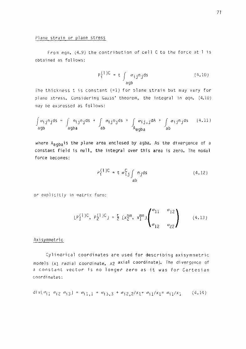
71
Plane s t r a i n or plane s t ress
From eqn. (4.9) t h e c o n t r i b u t i o n of c e l l C t o t h e f o r c e a t 1 i s
obta ined as f o l l o w s :
pj1 ) C = t f CT^-rK-ds (4.10) "IJ J
agb
The t h i c k n e s s t i s c o n s t a n t (=1) f o r p lane s t r a i n but may vary f o r
plane s t r ess . Cons ider ing Gauss' theorem, the i n t e g r a l in eqn. (4.10)
may be expressed as f o l l o w s :
CTijnJds = J a i j n j d s + J a i j n j d s = J ffij,jdA + J * i j n j d s ( 4 ' U )
agb agba ab ^agba a b
where Aaqt,ais the plane area enclosed by agba. As the divergence of a
constant f i e l d is n u l l , the integral over th i s area is zero. The nodal
force becomes:
p j 1 ^ = t fffj f njds (4.12)
ab
( CT11 CT12\
or e x p l i c i t l y in mat r i x fo rm:
LPJDC, p£l)Cj = t [ x n m j xmn j [ " " | ( 4 > 1 3 )
r12 CT22
Axisymmetric
C y l i n d r i c a l c o o r d i n a t e s are used f o r d e s c r i b i n g a x i s y m m e t r i c
models ( x i r a d i a l coo rd i na te , x2 a x i a l coo rd i na te ) . The divergence of
a c o n s t a n t v e c t o r i s no l o n g e r z e r o as i t was f o r C a r t e s i a n
c o o r d i n a t e s :
d i v L " i ! viZ * i 3 J = ffjn + ^ 3 3 + ^ i 2 , 2 / x l + o r i l / x i = ^ i i / X i (4 .14)

72
The c o n t r i b u t i o n of a c e l l C t o the i n t e g r a l i n eqn. (4 .9 ) becomes
/ ^ i j n j d S + j CTijnjdS = / ( ^ i/xl)Znx.ldh + I CTi j ^ / r x ^ j d s =
sagba sab Aagba a b
;4.15)
= (7r/6)ACor i l + 2 7T x } ^ - j |ab| n j b
where: S a q t ) a , S a b denote sur faces of r e v o l u t i o n generated by agba & ab
AC t o t a l Cel l area
A agba = AC/6 , area enclosed by t r i a n g l e agba
|ab| , n are the leng th and u n i t normal of segment ab
In a d d i t i o n t o the terms from eqn. (4.15), r a d i a l fo rces are produced
by t he hoop s t r e s s e s <733. These f o r c e s are not i n c l u d e d i n (4 .15 ) , as
t h e i n t e g r a l s c o v e r t h e c o m p l e t e 2 t o r o i d where o p p o s i t e r a d i a l
components cance l out ( f i g . 4 .3 ) . However , i f one c o n s i d e r s o n l y a
sec to r of angle <p :
PJD = r P ^ ) d = ^ D = J a33dA
and the c o n t r i b u t i o n of c e l l C f o r the complete 2 i s :
p{DC = 1 AZo332n= 2 j a 3 3 A C ( 4 < 1 6
wh ich added t o (4.15) g i v e s t h e t o t a l nodal f o r c e c o n t r i b u t i o n s . In
mat r ix fo rm,
y CT12 a 2 2 / (4 .17)
+ 6 A C L f f l l CT12J +
3 - A C C ^ 3 3 °J
4 .2 .2 MIXED DISCRETIZATION (MTQ, MTB ELEMENTS)
Mixed d i s c r e t i z a t i o n p rocedu res are d e s c r i b e d i n t h i s s e c t i o n .
Th is t e c h n i q u e s a v o i d t h e e x c e s s i v e s t i f f n e s s o therw ise assoc ia ted
w i t h constant s t r a i n t r i a n g l e s or t e t rahed ra f o r incompress ib le f l o w
(see sec t . 3 . 7 . 1 ) .

73
A c c o r d i n g t o iMagtegaal , Parks and Rice (1974) , f o r a c c u r a t e
mode l l i ng of i ncompress ib le p l a s t i c f l o w , the r a t i o between the number
of Degrees Of Freedom (DOF) in the mesh and the number of c o n s t r a i n t s
imposed by the i n c o m p r e s s i b i 1 i t y c o n d i t i o n must be > 1. For Constant
S t r a i n T r i a n g l e s , The r a t i o D O F / c o n s t r a i n t s f o r i n f i n i t e l y r e f i n e d
p l ane s t r a i n and a x i s y m m e t r i c meshes i s equal t o 1 ( c o n s i d e r i n g f o r
t h e a x i s y m m e t r i c case t h a t t h e r a d i a l l y v a r y i n g hoop s t r e s s e s are
reduced to the value at the element c e n t r o i d (eqn. 4.6), o the rw ise the
r a t i o wou ld be 1/3) ( t a b l e 3.1) . For t e t r a h e d r a f o r m i n g b r i c k s i n a
regu la r l a t t i c e , the r a t i o i s e i t h e r 3/5 or 3/6 depending on whether
each b r i ck i s composed of 5 or 6 t e t rahed ra ( tab le 3.1).
Nagtegaal e t a l . (1974) s u g g e s t e d a m o d i f i e d v a r i a t i o n a l
p r i n c i p l e to improve meshes which would o the rw ise be u n s u i t a b l e . The
idea behind t h i s m o d i f i c a t i o n i s to make sure d i l a t a t i o n i s governed
by f e w e r p a r a m e t e r s than f o r c o n v e n t i o n a l e l e m e n t s . S t a r t i n g f r o m
e l e m e n t s w i t h more than one i n t e g r a t i o n p o i n t , t h i s i s a c h i e v e d by
a v e r a g i n g t h e v o l u m e t r i c s t r a i n s w i t h i n each e l emen t ( e f f e c t i v e l y
p e r f o r m i n g a reduced i n t e g r a t i o n on t h e m ) . Based on t h e same
p r i n c i p l e , Mar t i and Cundall (1982) have proposed Mixed D i s c r e t i z a t i o n
(MD) p r o c e d u r e s v a l i d f o r FE or FD meshes w i t h l o w e r o r d e r e l e m e n t s
(one i n t e g r a t i o n p o i n t ) , i n which vo lume t r i c s t r a i n s are averaged f o r
groups of several e lements.
The i d e a l v a l u e f o r t he r a t i o D O F / c o n s t r a i n t s i s t h a t of t h e
cont inuum, in which f o r each ma te r i a l po in t t he re i s one vo lume t r i c
e q u a t i o n and U (no. of space d i m e n s i o n s ) DOF. Us ing MD these i d e a l
r a t i o s are a c h i e v e d i f a v e r a g i n g i s p e r f o r m e d w i t h i n t h e f o l l o w i n g
MD groups ( tab le 3 . 1 ) :
- 2 Tr iang les in one Q u a d r i l a t e r a l f o r 2-D (MTQ e lements ) ;
- 5 or 6 Tetrahedra in one Br ick f o r 3-D (MTB e lements ) .
I f Ci ( i = l t o M) s tands f o r t h e i n d i v i d u a l c e l l s and £ f o r t h e
t o t a l e l emen t (MTQ or MTB), t h e M ixed D i s c r e t i z a t i o n p r o c e d u r e
c o n s i s t s s imp ly of s u b s t i t u t i n g the vo lume t r i c s t r a i n s in each c e l l by
the volume-weighed average of the group:

4.3: Radial forces from Hoop stresses (axisymmetric mooel)
.40
20
oo
80
60
40
20
00
80
60
40
20
00
CORRECTED M.D. ( MTQCELEMENTS) ORDINARY M.D. (MTQ ELEMENTS) NO M.D. (CST ELEMENTS)
E = "V =
Y -.
= 67x10 ' = 0 . 3 -- 120x10
0.00 0.20 0.40 0.60 0.80
ADIMENSIONAL DISPLACEMENT. 2wd/a
Figure 4.4= RESISTANCE TO ZERO-VOLUME FOR DIFFERENT ELEMENT TYPES

75
M M
i = l i = l
where V^i are the volumes of the i n d i v i d u a l c e l l s . M=2 f o r 2-0 and M=5
or 6 f o r 3-D. For ax i s y m m e t r i c m o d e l s , t h e average i n eqn. (4.18) i s
a r e a - w e i g h e d i n s t e a d , i n o r d e r t o a v o i d p rob l ems near t h e a x i s o f
symmetry.
Apart f rom having the idea l number of vo l ume t r i c c o n s t r a i n t s , MTQ
or MTB e l e m e n t s w i l l p roduce n o n - z e r o s t r a i n s and s t r e s s e s i n t h e
component c e l l s f o r any se t of c o r n e r movements. No z e r o - e n e r g y
hourg lass ing may occur, as i t i s opposed by d e v i a t o r i c s t resses .
V a l i d a t i o n examples f o r MO p rocedu res i n s i m p l e p l a s t i c i t y
problems are prov ided i n s e c t i o n s 5.4.1 and 5.4.2.
4 .2 .3 PREVENTION OF NEGATIVE VOLUMES (MTQC, MTBC ELEMENTS)
One impor tan t advantage of CST elements i s t h a t no t a n g l i n g over
may occur w i t h o u t o c a s s i o n i n g n e g a t i v e vo lumes i n t h e bas i c c e l l s
(Johnson, 1976). A hypoe las t i c ma te r i a l w i l l generate r e s i s t i n g forces
t h a t grow towards i n f i n i t e as the volume tends to zero. This advantage
i s l o s t by MO, w h i c h a c c e p t s ze ro vo lume i n one c e l l w i t h o u t
generat ing i n f i n i t e r e s i s t i n g pressures, as long as the whole MO group
has a non-zero volume. This may be seen l e t t i n g the volume of one c e l l
Cj tend to zero:
i f V C j — * 0
CST: Z\P = K4€§J = K(/AVC:i/VCj ') —* - CO
MO : 4P = K 4 6 v = K(4e§Jv C : i +y ^ C i vC l ) / v E - ^ > K ( \ A6§ 1 V C l ) /V E
i t J i 3*j
( f i n i t e )
This f a c t has a number of u n d e s i r a b l e s i d e - e f f e c t s . Large
reduct ions in volume are u s u a l l y assoc ia ted w i t h la rge d i s t o r t i o n s in

76
s h a p e , c a u s i n g c o n s i d e r a b l e n u m e r i c a l e r r o r s as the e l emen t
i n t e r p o l a t i o n s become i l l - c o n d i t i o n e d . On the other hand, the c r i t i c a l
t i m e - s t e p w i l l be reduced, i nc reas ing the costs g r e a t l y . F i n a l l y , i f
n e g a t i v e v o l u m e s o c c u r f r o m t a n g l i n g o v e r i n t h e m e s h , t h e
c a l c u l a t i o n s w i l l crash. I t must be no ted t h a t t hese p r o b l e m s occu r
o n l y f o r s p e c i a l cases w i t h h i g h l y d i s t o r t e d L a g r a n g i a n meshes.
However they do d e t r a c t s e r i o u s l y f rom the robustness of MD procedures
f o r general a p p l i c a t i o n s .
Johnson (1981) has recognized t h i s prob lem, but his s o l u t i o n has
been an i n c o n s i s t e n t use of averaging procedures. For c e r t a i n c r i t i c a l
po r t i ons of the c a l c u l a t i o n s , averaging i s sw i tched o f f , i n order not
t o i n c u r i n o v e r l a p p i n g . No e x p l a n a t i o n i s g i v e n by Johnson f o r t h e
i n e v i t a b l e loss of accuracy, except the convenience of the ana l ys t .
A c o n s i s t e n t s o l u t i o n i s p r o p o s e d h e r e u s i n g a M i x e d
D i s c r e t i z a t i o n mesh tha t recovers the res is tance to negat ive volumes
of CST e lements , when f o r an i n d i v i d u a l c e l l the volume tends to zero ,
V !-'J->U. Th is t a k e s t he shape of a c o r r e c t i o n t o t he averaged
v o l u m e t r i c s t r a i n i n c r e m e n t (A€v) f r o m eqn. (4 .18 ) :
AeJ1 := A(£ +amin(Ae§J,0) i ;vE / (MVC i) - 1J (4.19a)
where M i s the number of c e l l s i n the MD group, and a i s an e m p i r i c a l
c o e f f i c i e n t (a=0.01 i s the recommended d e f a u l t va lue) . This c o r r e c t i o n
only operates when vo l ume t r i c s t r a i n increments in the sma l l es t c e l l
of the group are compressive ( i . e . c e l l volume i s being decreased).
I t can be seen e a s i l y t ha t t h i s c o r r e c t i o n (eqn. 4.19) conserves
the volume weighed average, thus m a i n t a i n i n g the cons is tency of the
computa t ions . C a l l i n g the new average {Ae\j):
( ^ ^ ( J ^ e ^ v 0 1 ) /vE= ^ e ^ + o ; m i n ( z \ e 5 J , 0 ) ( l / V E ) ^ [ ( V E v C i ) / ( M V C i ) - V C i J
(4.19b)
where the second term on the r i g h t hand s ide i s n u l l , as V = ) V .
On the o t h e r hand, when t h e c e l l vo lume tends t o ze ro t h e
v o l u m e t r i c s t r a i n i n c r e m e n t grows a s y m p t o t i c a l l y , p r o d u c i n g an

77
infinite resistance to,tangling over
f0r v C j — » 0, d€§J := ^ +Q!min(Z\e5J,0)LVE/(MVCJ)-lJ — » -oo (4.20)
For axi symmetr ic problems, again the c o r r e c t i o n fo rmula must be
area w e i g h e d . In o r d e r t o p r e s e r v e t h e v o l u m e - w e i g h e d average (eqn.
4.19b) the axi symmetr ic c o r r e c t i o n takes the form
A€^ := Ae£ + a m i n ( 4 e 5 J , 0 ) [ A E / ( M A C i ) - l J r E / r C i (4 .21)
where A , A are areas of the i n d i v i d u a l c e l l s and complete element
r , r are the r a d i a l coord ina tes of t h e i r c e n t r o i d s .
The new e l e m e n t s c r e a t e d by t h i s c o r r e c t i o n a g a i n s t n e g a t i v e
volumes in MO procedures w i l l be c a l l e d :
MTQC (MTQ co r rec ted ) f o r 2 -0 ;
PlT'tlC (MTB c o r r e c t e d ) f o r 3-0 .
A s i m p l e t e s t w i t h a q u a d r a n g l e , i n wh i ch one of t he component
t r i a n g l e s tends to zero volume, was done to v e r i f y the behaviour of
t hese e l e m e n t s ( f i g . 4 .4 ) . For Cons tan t S t r a i n T r i a n g l e s (CST), t he
r e s i s t i n g fo rce grows towards i n f i n i t y when a node t r i e s to cross over
t h e o p p o s i t e s i d e . MTQ and MTQC e l e m e n t s d i s p l a y a s o f t e r r e s p o n s e ,
both being near ly i d e n t i c a l up t o 90% reduc t ion in volume. For f u r t h e r
reduc t i ons , the res i s tance of MTQC elements shoots up s teep ly towards
i n f i n i t y , w h i l e MTQ a l lows c ross ing over (negat ive volume).
This impor tan t r e s u l t means t h a t the new proposed elements are
capable of accu ra te l y mode l l i ng incompress ib le p l a s t i c f l o w , even f o r
s i t u a t i o n s w i t h ve ry l a r g e d i s t o r t i o n s , but r e c o v e r t h e d e s i r a b l e
r e s i s t a n c e o f CST meshes t o o v e r l a p p i n g . F u r t h e r r e s u l t s u s i n g MTQC
elements are presented in sec t ions 5.4, 5.7, and 7.3.4.4 which c o n f i r m
t h i s p o i n t .

78
4.2.4 MASS LUMPING PROCEDURE
The mass in the discrete model is lumped at the gr id -po in ts , by
in tegrat ing the continuum mass over a volume surrounding each node.
For a Lagrangian mesh, nodal masses need only be computed once, at the
beginning of the ca lcu lat ions. Two condit ions must be met by the mass
lumping procedure: f i r s t l y the centre of gravi ty must be preserved for
dynamic c a l c u l a t i o n s , and secondly the volume of i n t e g r a t i o n , f o r
consistency, must correspond to the surface used when in tegrat ing the
st resses ( f i g . 4.2).
The c o n t r i b u t i o n of a c e l l C to the mass of node 1 is ( f i g . 4.2):
- Plane stress or plane s t ra in
PValbg = P t A a l b g = PtAim n /3 (4.22) (1/3 of the mass to each node)
- Axisymmetric
Pvalbg = P f 2 7 r r d A =p(7T/54)A lmn(22r1 + 7rm + 7rn) (4.23) Aalbg
For 3-D, l / 4 t h of the mass of every te t rahedron is lumped at each of
i t s nodes.
4.3 MOMENTUM BALANCE
Having integrated the stresses (eqn. 4.9) and obtained the nodal
masses (eqns. 4.22, 4.23), balance of momentum i s app l ied l o c a l l y ,
us ing the i n t e g r a l form of the p r i n c i p l e (eqn. 2.28). Note tha t the
corresponding f i e l d equat ion (Cauchy's eqn. of mo t ion , (2.29))
requires a stronger d i f f e r e n t i a b i l i t y , which is not sa t i s f i ed at the
element in ter faces.
Integrat ing over a small surface s ( ^ around each node 1,
u ( 1 ) = [ / crndS + M^1 ) f + R^1 ) ] / M ( 1 ) (4.24) JS(D
where: R^ ' are intensive forces applied on node 1
IV ' is the mass lumped at 1.

79
4.4 CENTRAL DIFFERENCE TIME INTEGRATION
The accelerations are integrated in time with a centred scheme to provide new values for velocities and displacements:
•n+1/2 = Qn-1/2 + j j n ^ (4#25)
un+l = un + ^n+1/2^ (4>26)
Note that all the variables representing rates or increments are defined at mid-step. The central difference equations (4.25, 4.26)
together with the discretized momentum balance eqns. (4.24), form an
uncoupled system, which may be solved independently for each node in
the mesh.
The numerical dispersion (frequency distortion errors) associated
with a lumped mass idealization and a central difference scheme are of different signs (Key, 1978), which makes this combination a natural
choice for explicit models.
4.5 CONSTITUTIVE MODELS
Explicit schemes allow a great generality in the constitutive laws that can be modelled. In principle, any law that can be expressed explicitly in the following rate form is acceptable:
8= C(E,d, ff.K.T) (4.27)
where: <j represents an object ive stress rate (section 2.5.1)
K is a set of material parameters
T is the temperature
E is Green's s t ra in tensor
d is the rate of deformation tensor.
For the present work, the c o n s t i t u t i v e laws considered are
e las t i c -p las t i c models with Von Mises y i e l d c r i t e r i o n . A hypoelastic
p r e d i c t i o n is computed f i r s t , and then co r rec ted back to the y i e l d
surface i f the y i e l d condit ion is exceeded (radial return). For a more

8Q
complete study of c o n s t i t u t i v e laws in e x p l i c i t F i n i t e Di ference
Lagrangian codes, see Herrmann and Bertholf (1983).
4 . 5 . 1 HYPOELASTICITY
The basic (predictor) cons t i tu t i ve behaviour is a hypoelastic law
of the type:
CT^ = A d k k 5 i j + 2Gdij - a(3A+2G)f<$ij (4 .28)
where A,G are Lame's e las t ic constants
T is the temperature rate
t r i s the coe f f i c ien t of thermal expansion
Hypoelast ic s t resses are computed always as p r e d i c t o r s , being
la ter corrected for other types of behaviour i f needed. Al l stress and
deformat ion measures used in eqn. (4.28) r e f e r to the cu r ren t
conf igura t ion ; i t produces a l inear re la t ion between true stress and
na tu ra l s t r a i n in a u n i a x i a l t e s t . For la rge s t r a i n s (4.28) does not
der ive from an e l a s t i c p o t e n t i a l ( h y p e r e l a s t i c ) . For smal l s t r a i n s ,
both concepts are equivalent.
4 . 5 . 2 PLASTICITY; RADIAL RETURN ALGORITHM
The p l a s t i c y i e l d c r i t e r i o n is a s t ress c o n d i t i o n , d e f i n i n g a
y i e l d surface in s t ress space. The y i e l d c r i t e r i o n depends on the
history of deformation, through the p las t i c hardening parameters, Q:
F((7,Q) = 0 (4 .29)
The t r i a l stress from the hypoelastic predict ion (eqn. 4.28) ,
C7[? + 1 =Gn + <j£+1 /2 /U (4.30)
i s tes ted w i t h the y i e l d c r i t e r i o n , eqn.(4.29). I f F(<7£+1)<0 no
correct ion is necessary:
0* + 1 = GnE
+1 (4.31)

81
I f F ( a ^ + 1 ) > 0 the s t resses are re tu rned norma l l y to the y i e l d sur face
( f i g . 4 . 5 ) :
a n + l = a n + l _ ( / 5 / 3 ) ^ { 4 > 3 2 )
Aon+l/Z - an+l - a n
where /3 i s a sca la r f a c t o r , used f o r convenience of p resen ta t i on . The
new st resses must s a t i s f y F ( < j n ) = 0.
Th i s r a d i a l r e t u r n method i s due t o W i l k i n s (1964) . Other (more
s o p h i s t i c a t e d ) methods f o r c a l c u l a t i n g the s t ress update e x i s t , such
as t h e t a n g e n t s t i f f n e s s r a d i a l r e t u r n (e .g . K r i e g and Key, 1976). A
v a r i a t i o n t o t h e r a d i a l r e t u r n me thod , a p p l y i n g t h e c o n s i s t e n c y
c o n d i t i o n t o t he end s t a t e r a t h e r t han i n a d i f f e r e n t i a l sense has
a l s o been proposed by K r i e g and Key (1976) . R e c e n t l y , O r t i z and Simo
(1985) have proposed more gene ra l " r e t u r n mapping a l g o r i t h m s " , f o r
a r b i t r a r y p l a s t i c models and non-constant tangent e l a s t i c i t y t enso rs .
R e s u l t s o b t a i n e d here (e .g . s e c t . 5.6) i n d i c a t e t h a t f o r t h e s m a l l
e x p l i c i t s t eps u s e d , even i n h i g h l y n o n - l i n e a r c a l c u l a t i o n s , t h e
performance of the s imp les t r a d i a l r e tu rn method i s acceptab le .
The ra te of de fo rmat ion tensor is composed of e l a s t i c and p l a s t i c
p a r t s :
d = de+ d p (4 .33)
The elastic component may be expressed as
d E = l _ s + L l a s + 9KT a J • (4.34) ij 2G ij E kk ij
wh ere s-jj are the d e v i a t o r i c s t resses (eqn. 2 . 5 9 ) , and K= A+2G/3.
In t h e f o l l o w i n g , i t w i l l be assumed t h a t t h e y i e l d s u r f a c e i s a Von
Mises c y l i n d e r , w i t h no dependence on h y d r o s t a t i c s t r e s s e s . The
p l a s t i c c o r r e c t i o n (4.32) t a k e s p l a c e i n t h e d e v i a t o r i c h y p e r p l a n e
(^ k k = c o n s t a n t ) , as W- = 35- Hence, t he v o l u m e t r i c s t r e s s - s t r a i n
behaviour is pure ly e l a s t i c :

8?
n S-c* 2 G \ r A S E
2GA< 2GA^
s^i-w
c*
Figure 4.5: Radial return plastic stress correction

ffkk = <^k = 3K(dkk - 31a ) (4.35)
The ra te of de format ion may be expressed inver t ing eqn. (4.28):
d i i = J _ s^j + I ( ^kk +9KTa) 5^- (4.36) 2G E
The p l a s t i c r a t e o f d e f o r m a t i o n i s d e r i v e d c o m b i n i n g eqns.
( 4 .32 ) , ( 4 .33 ) , (4.34) and (4 .36 ) :
dP = d - dE = l_(sE - s) = MldL (4.37) 2G 2G do
Hence the r e t u r n a l g o r i t h m (eqs. 4.30 - 4.32) i m p l i c i t l y d e f i n e s a
no rma l i t y ru le f o r the p l a s t i c f l ow ( a s s o c i a t i v i t y ) .
In p a r t i c u l a r , f o r a Von Mises y i e l d c r i t e r i o n w i t h k i n e m a t i c -
i s o t r o p i c hardening of the type
F = ( 3 / 2 ) ( S i j - « i j ) ( s i j - a - j j ) - Y2 (4 .38)
if the plastic condition is reached (F(ajr ) > 0), the deviatoric
stresses are simply scaled back along the radius of the Von Mises
ci rcle (fi g. 4.5):
s-1]1- «ij = ((s?} 1^ -« i j)/(l+/3) (4.39)
and i f the hardening is purely isot ropic ( a ^ = 0 ) :
s? ] 1 = (s rj1 j 1 ) E / ( l+ /J ) (4.40)
The plane s t ress c o n d i t i o n ^33=0 requires special treatment in
the e l as t i c -p l as t i c a lgor i thm. I f the ma te r i a l behaves e l a s t i c a l l y ,
plane s t ress i s enforced i m p l i c i t l y by s e t t i n g ( in terms of the
incremental s t ra ins , eqns. (4 .7 ) , ( 4 .8 ) ) :
A633 = V— {A6n + A€Z2) ( 4 . 4 1 ) l-v
If plastic deformations occur within the step, an exact one-step

84
a l g o r i t h m en fo r c i ng the plane s t ress c o n d i t i o n i s not poss ib le (as the
p l a s t i c c o r r e c t i o n i s s t ress-dependent ) . I t may be achieved app ly ing
t he f o l l o w i n g c o r r e c t i o n s a f t e r t h e r a d i a l r e t u r n (eqn. 4.32) i s
per formed:
'am : = "^33
Aev := A(Jm/(A+2G/3) (4.42)
Ae^ := Ae^ + (1/3)(A€° - A6y)8^
where: am = (1 /3 ) a ^ , mean s t ress
Ae° = p red ic ted vo lumet r i c s t r a i n
This c o r r e c t i o n imp l ies a s/ery s l i g h t vo lumet r i c n o n - a s s o c i a t i v i t y ,
<+l = U £ + 1 ) E / U + ^ ) (4-43)
wh ich has no e f f e c t f o r d e v i a t o r i c p l a s t i c i t y c r i t e r i a (e .g . Von
M ises ) .
4 .5 .3 HARDENING AND UNIAXIAL STRESS-STRAIN LAWS
P l a s t i c s t r a i n s g ive r i s e to ma te r i a l hardening. For a k i n e m a t i c -
i s o t r o p i c Von Mises model (eq. 4.38) t he h a r d e n i n g i s composed of a
k i n e m a t i c t r a n s l a t i o n ( « - j j and an i s o t r o p i c expans ion (Y) of t he
y i e l d su r face :
0 9 p
3 (4 .44 ;
AY = h Y A e p
where ^e P = - Ae^ Ae^A (effective plastic strain increment)
ha and hy are the kinematic and isotropic moduli respectively
The plastic hardening modulus in uniaxial tension is

85
h' = h a + hY (4.45)
I f ha = 0, hardening is pure ly i s o t r o p i c ; i f hY = 0, i t is pure ly
kinematic.
Un iax ia l s t r e s s - s t r a i n laws may be def ined as the t r ue ax ia l
stress - natural axial s t ra in curves in uniaxia l tension tests (sect.
6.2) :
o= f ( € ) (4.46)
where the n o t a t i o n a= ^ n , e= e n has been used. Decomposing the d i f f e r e n t i a l s t ra in increment in to e las t ic and p las t i c components,
de = deE + dep = da( l /E + 1/h") (4.47)
the to ta l s t ress-s t ra in modulus may be expressed as
h = ^L = I ( 4 . 4 8 ) de 1/E+l/h'
Un iax ia l s t r e s s - s t r a i n laws are convenient f o r s p e c i f y i n g
isot ropic material behaviour. A few examples of laws used w i th in th is
work are given in f igure 4.6.
The y i e l d condit ion may depend also on the s t ra in - ra tes and the
tempera tu re , which prov ide a d d i t i o n a l sources of hardening (or
sof tening, as the case may be):
Y = Y 0 ( / ) f R ( e P ) f T ( T ) (4.49)
Functions f^ (s t ra in - ra te dependence) and f j (temperature dependence)
may be defined as piecewise l inear laws. A useful analyt ica l form for
fR is (Bodner and Symonds, 1960):
f R (e P ) = 1 + (eP /B)m (4.50)
where m and B are ma te r i a l cons tan ts . Eqn. (4.50) is equ iva len t to a

h=1/ (l/h'+l/E)
o = Ee (o<o„)
o = o0+he (o>o0)
NATURAL STRAIN. .
A) BILINEAR ELASTIC-PLASTIC
NATURAL STRAIN.
B) PIECEWISE LINEAR ELASTIC-PLASTIC
o0e0 n e
o = Ee (o<o„) o /o„= (e/e„) " (o>o0)
NATURAL STRAIN.
C) POWER LAW E L A S T I C - P L A S T I C
Fiqure 4.6: Uniaxial s t ress-s t ra in laws implemented in numerical model
'A • = min. Area i ' rrnn i of any element) |
NODE-NOD^ I
IpQSVAmin
NODE-SIDE
NODE-NODE
K
Finure 4.7: Node to node and node to side contacts - regions and normals
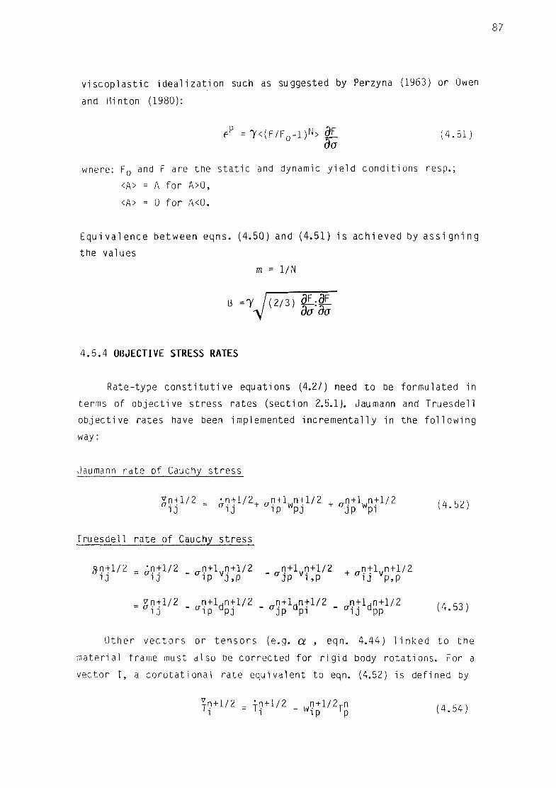
87
v i s c o p l a s t i c i d e a l i z a t i o n such as suggested by Perzyna (1963) or Owen
and Hinton (1980):
ep = 7 < ( F / F 0 - i ) N > df_ (4 .51) do
where: F0 and F are the static and dynamic yield conditions resp.;
<A> = A for A>0,
<A> = 0 for A<0.
Equivalence between eqns. (4.50) and (4.51) is achieved by assigning
the values
m = 1/N
•i B =7 1(2/3) &-:§^
4.5.4 OBJECTIVE STRESS RATES
Rate-type c o n s t i t u t i v e equat ions (4.27) need to be fo rmu la ted in
terms of o b j e c t i v e s t ress rates (sec t ion 2.5.1). Jaumann and Truesde l l
o b j e c t i v e ra tes have been implemented i n c r e m e n t a l l y in the f o l l o w i n g
way:
Jaumann ra te of Cauchy s t ress
SO + 1/2 = a n + 1/2+ an+V + l/2 + ffn + lwn + l / 2 ( 4 5 2 ) 1J 1J ip WPJ JP Wpi 1<+.D£,|
Truesde l l r a te of Cauchy s t ress
Sn+1/2 = ^n+1/2 _ n + l n + 1 / 2 n+ l . .n+ l /2 , n + l n + 1 / 2 i J i J ip VJ,P CTJP v i , P U VP,P
= gn+1/2 _ n + l d n + l / 2 _ n + l d n + l / 2 _ n + l d n + l / 2 ( 4 5 3 )
1J " i p UPJ UJP U p i CT1J UPP \*.03)
Other vectors or tensors (e.g. a , eqn. 4.44) linked to the
material frame must also be corrected for rigid body rotations. For a
vector T, a corotational rate equivalent to eqn. (4.52) is defined by
^n+1/2 = i n +l/2 _ n+l/2Tn ( 4 > 5 4 )

88
Note t h a t t h e r e i s h a l f a s tep l a g f o r t h e v a l u e s of s t r e s s e s i n eqns.
(4.52) - (4 .54) . For e x p l i c i t i n t e g r a t i o n i n w h i c h s teps a re very
small e r r o r s in t roduced by t h i s w i l l not be impor tan t (sect . 5.6). For
l a r g e r i m p l i c i t s teps , more r igorous a l go r i t hms have been proposed by
Hughes and Winget (1980) , P i n s k y , O r t i z and P i s t e r (1983) , and
Rub ins te in and A t l u r i (1983) .
Jaumann's r a t e i s t he most commonly used f o r m u l a t i o n , be ing a
na tu ra l choice f o r removing r i g i d body r o t a t i o n s (Prager, 1961). Some
incons i s tenc ies may a r i s e however in la rge de fo rmat ion s imple shear
w i t h k i n e m a t i c h a r d e n i n g (Nagtegaa l and de Jong (1982) , D a f a l i a s
(1983), Lee and M a l l e t t (1983)). On the other hand T ruesde l l ' s ra te i s
t h e f o r w a r d P i o l a t r a n s f o r m a t i o n of t h e r a t e o f 2nd P i o l a - k i r c h o f f
s t ress and provides a "canon ica l " form f o r h y p e r e l a s t i c r a t e equat ions
(Pinsky, O r t i z and P i s t e r , 1983).
Both T r u e s d e l l and Jaumann r a t e s can be made e q u i v a l e n t by
a p p r o p r i a t e d e f i n i t i o n o f t h e c o n s t i t u t i v e t e n s o r (eqn. 3 .28) . The
c l a s s i c a l e l a s t i c - p i a s t i c r e l a t i o n s (Prandt l -Reuss eqns. (2.64)) are
exp ressed i n t e r m s of t r u e s t r e s s and t r u e s t r a i n ( H i l l , 1950) . The
a s s u m p t i o n i s made h e r e , as by H i b b i t , Marca l and Rice (1970 ) , t h a t
the Prandt l -Reuss equat ions are r e f e r r e d t o Jaumann rates of s t resses .
4.6 DAMPING
The semid i sc re te equat ions of motion (4.24) may be assembled in
ma t r i x form f o r the complete model, and genera l i zed to inc lude v iscous
dampi ng:
Mii + Cii + P = R (4 .55)
where M i s the diagonal mass m a t r i x , C i s the damping m a t r i x , and P, R
represent i n t e r n a l and ex te rna l fo rces r e s p e c t i v e l y .
A u s e f u l f o r m f o r t h e damping m a t r i x i s t h e s o - c a l l e d R a y l e i g h

89
damping:
C = AM + BKt (4 .56)
where: Kt is t n e tangent s t i f f n e s s m a t r i x , !Ct=dP/du
A, B are the mass and s t i f f n e s s damping c o e f f i c i e n t s .
R a y l e i g h damping a l l o w s eqns. (4.55) t o rema in u n c o u p l e d , and
t h e r e f o r e i s e a s i l y implemented in an e x p l i c i t code. Mass damping i s
i n t e g r a t e d i n t o the t ime-march ing scheme (eqns. (4.25), (4.26)) by the
f o l l o w i n g ope ra to r :
u n + 1 / 2 = [ u n _ 1 / 2 ( l - A / i t / 2 ) + M _ 1 ( R n - P n ) 4 t J / ( l + A A t / 2 ) (4 .57)
w h i c h i m p l i e s a m o d i f i c a t i o n o f t h e t i m e - i n t e g r a t i o n eqn. (4 .25 ) .
S t i f f n e s s damping i s cons idered by adding viscous f o r ce terms to the
i n t e r n a l f o r c e s :
p*n = Pn + B6ndPn/du (4 .58)
approximated in f i n i t e d i f f e r e n c e form by
P *n = pn + B A P n + l / 2 M t
S t i f f n e s s damping i s considered by s u b s t i t u t i n g Pn i n eqn. (4.57) by
p*n.
The amount of damping p r o v i d e d by (4.56) i s a f u n c t i o n of t h e
f r e q u e n c y . I f t h e sys tem of eqns. (4.55) i s put i n modal f o r m
(assuming t a n g e n t l i n e a r b e h a v i o u r and s m a l l d i s t u r b a n c e s ) , one
equat ion of the f o l l o w i n g type i s obta ined per mode:
x + (A+B a»2)x + <w2x = r (4 .58)
where x i s the modal ampl i tude and a> the frequency of v i b r a t i o n . The
amount of damping f o r each frequency co i s given by
/5 = (A/w + Bft> )/2 (4 .59)

90
where ft =1 corresponds to the c r i t i c a l damping. From eqn. (4.59) i t
may be seen t h a t the e f f e c t of mass damping i s smal l f o r h igh
frequencies, where s t i f fness damping is important, and viceversa. Mass
damping may be l ikened to dashpots connecting each degree of freedom
to ground, and s t i f fness damping to dashpots between connected nodes.
4.7 STABILITY OF TIME INTEGRATION
Four ier methods (e.g. Richtmeyer and Mor ton, 1967) may be used
for studying the s t a b i l i t y of l inear systems and small perturbat ion
tangent behaviour in non l inear systems. The d i f f e r e n t i a l modal eqns.
(4.58) may be rewr i t ten as
x + Zjicox + coZx = 0 ( 4 . 6 0 )
from which the ex te rna l f o r c i n g f u n c t i o n ( r ) has been dropped. The
harmonic solut ion to t h i s equation is
x n = e>>nAt = An ( 4 > 6 1 )
where V, A are complex numbers (note the s u p e r s c r i p t on A i s an
exponent). S u b s t i t u t i n g eqn. (4.61) w i t h i n c e n t r a l d i f f e r e n c e eqns.
(4.25 - 4.26) one obtains
xn = (xn + 1-2xn + x n ' 1 ) M t 2 = An-l(AZ-ZA+l)/At2
•n = ( X n + l _ x n - l ) / 2 4 t = An-l(A2-l)/ZAt
!4.62
which with eqn. (4.60) y i e l d
A2(l+Atw/5) + A(^ 2 At 2 -2) + (1-AtwA) = 0 (4.63;
for s t a b i l i t y , the solut ion A to t h i s equation must be complex and of
modulus not greater than 1 . These condit ions impose
fi >, 0
At < IJl-d2 ( 4 . 6 4 , O)

91
The second condition must be satisfied for all the frequencies
present in the model. As damping is usually small, a sufficient
condition will be
At < 2.V1_/32 (4.65) CO
max
Damping has an adverse e f f e c t on s t a b i l i t y , a l though s t i f f n e s s
and mass damping behave d i f f e r e n t l y in t h i s respect. Considering that
the condit ion (4.55) applies for the highest frequency of the model,
from eqn. (4.59) i t may be seen that mass damping w i l l v i r t u a l l y have
no e f fec t , while s t i f fness damping may be very det r imenta l .
For undamped motion ( /3 =0) the c r i t i c a l t ime-step reduces to
At < 2/o>max (4.65)
An upper bound expression for the c r i t i c a l t ime-step is given by the
Courant c r i t e r i o n (Courant, Fr iedrichs and Lewy, 1928), which l i m i t s
the t ime-step to the in terva l necessary for the stress-waves to t ravel
across one element,
At < nmin/c (4.66)
where hmin ^s t n e m ' i i r ' ,T1um element dimension, and c the maximum st ress-
wave v e l o c i t y . For an e l a s t i c - p l a s t i c ma te r i a l the f a s t e s t s t ress
waves are the compressional or "P" waves, for which c = -J{A+2Gi)/p .
4.8 MODELLING OF CONTACTS
Contact between d i f fe ren t boundaries of one or more continua is
frequent in impact modelling and imposes special nonlinear boundary
c o n d i t i o n s . Two main aspects are i nvo lved in con tac t m o d e l l i n g : the
contact in ter face laws and the detection of in te rac t ing surfaces.
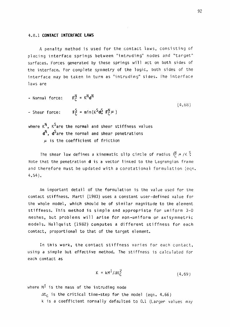
92
4.8.1 CONTACT INTERFACE LAWS
A penal ty method i s used f o r the contac t laws , c o n s i s t i n g of
p lac ing i n t e r f a c e spr ings between " i n t r u d i n g " nodes and " t a r g e t "
surfaces. Forces generated by these springs w i l l act on both sides of
the in ter face. For complete symmetry of the log ic , both sides of the
i n t e r f a c e may be taken in t u rn as " i n t r u d i n g " s ides . The i n t e r f a c e
laws are
Normal force: F? = KNdN C
(4.68)
- Shear force: F£ = min(Ksdf Fg/* )
where K , K^are the normal and shear s t i f fness values
d , d are the normal and shear penetrations
fj. is the coef f i c ien t of f r i c t i o n
The shear law defines a kinematic s l i p c i r c l e of radius FQ ^ /K ^
Note that the penetration d is a vector l inked to the Lagrangian frame
and t h e r e f o r e must be updated w i t h a c o r o t a t i o n a l f o r m u l a t i o n (eqn.
4.54).
An important deta i l of the formulat ion is the value used for the
contact s t i f fness . Marti (1983) uses a constant user-defined value for
the whole model, which should be of s im i l a r magnitude to the element
s t i f f n e s s . This method i s s imple and app rop r i a te f o r un i f o rm 3-D
meshes, but problems w i l l a r i se f o r non-un i fo rm or ax isymmet r i c
models. H a l l q u i s t (1982) computes a d i f f e r e n t s t i f f n e s s f o r each
contact, proportional to that of the target element.
In t h i s work, the contac t s t i f f n e s s va r ies f o r each c o n t a c t ,
using a simple but e f fec t i ve method. The s t i f fness is calculated for
each contact as
K = Ml/Atl ( 4 # 6 9 )
where M is the mass of the in t rud ing node
Atc is the c r i t i c a l t ime-step for the model (eqn. 4.66)
k is a coe f f i c ien t normally defaulted to 0.1 (Larger values may

93
cause i n s t a b i l i t i e s i f a corresponding reduction is not used for
the computational t ime-step)
This form f o r the contac t s t i f f n e s s ensures a value below the
maximum element s t i f f n e s s in the model (thus not compromising
s t a b i l i t y ) and above the s t i f f n e s s of the element in contac t (thus
avoiding unacceptable penetrat ions):
- maximum element s t i f fness - Kmax = ( l /4 )V c r (A+2G) /h2 i n
- contact s t i f fness - KQ = 2kVcr(A+2G)/hm-jn
- interface ( target) element s t i f fness - KT = (1 /4)VT (A +2Gvh^ in
where Vcr i s t n e v o ^ u m e ° f t n e element giv ing the c r i t i c a l t ime-s tep,
and VT that of the inter face target element.
This der ivat ion of the contact s t i f fness also produces a uniform
"push-back" recovery ac t i on along the contac t i n t e r f a c e , which is
impor tant s p e c i a l l y f o r ax isymmetr ic models, where the element
s t i f f n e s s e s and masses are radius dependent. This may be shown by
considering the accelerations at the in t rud ing side (a1) and target
side (aT) for a given penetration d:
a I = FQ/M 1 = Kd/At^
(4 .70)
aT = FC/MT = (KdMt^)(M I/MT)
Assuming the mesh is uniform on both sides of the in ter face ( M * / M T = 1 ) ,
for symmetric (double) contacts the recovery of the penetration in one
time-step w i l l be
dR = 2 ( l / 2 ) ( a I + a T )At 2 = Kv2d (4 .71)
where At=rjAtc is the computational t ime-step ( * /< l ) . The mesh can be
non-uniform along the contact in te r face , but should generally not be
too d i f fe ren t accross i t ( M ^ M 1 ) . The frequency of the contact spring
connecting M^ and M w i l l be proport ional to
(K/At£) MJ/M
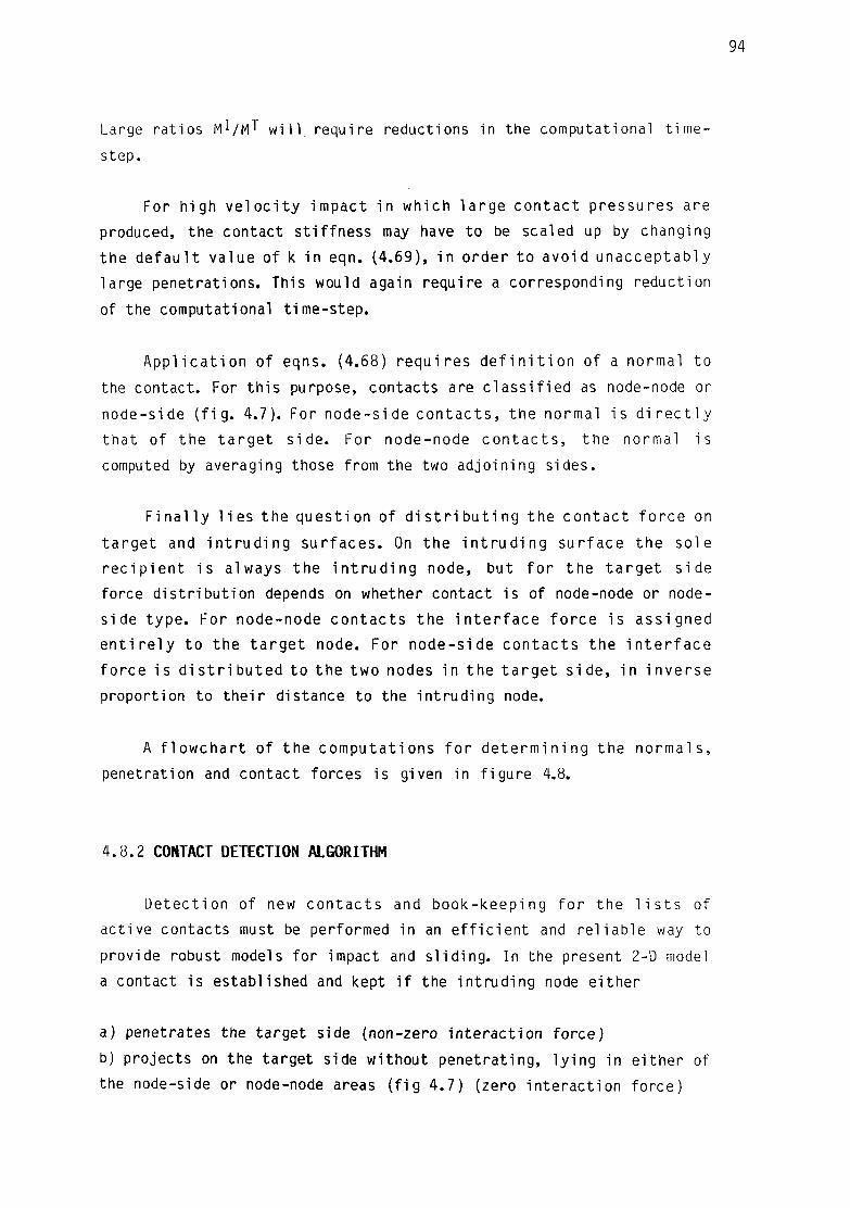
94
Large rat ios M^/MT w i l l , require reductions in the computational t ime-
step.
For high v e l o c i t y impact in which la rge contac t pressures are
produced, the contact s t i f fness may have to be scaled up by changing
the d e f a u l t value of k in eqn. (4.69), i n order to avoid unacceptabiy
large penetrations. This would again require a corresponding reduction
of the computational t ime-step.
A p p l i c a t i o n of eqns. (4.68) requ i res d e f i n i t i o n of a normal to
the contact. For th i s purpose, contacts are c l a s s i f i e d as node-node or
node-side ( f i g . 4.7). For node-side c o n t a c t s , the normal i s d i r e c t l y
tha t of the t a r g e t s ide . For node-node c o n t a c t s , the normal i s
computed by averaging those from the two adjoining sides.
F i n a l l y l i e s the quest ion of d i s t r i b u t i n g the con tac t f o rce on
t a rge t and i n t r u d i n g sur faces . On the i n t r u d i n g sur face the sole
r e c i p i e n t is always the i n t r u d i n g node, but f o r the t a r g e t s ide
force d i s t r i bu t i on depends on whether contact is of node-node or node-
side type. For node-node contac ts the i n t e r f a c e f o r ce is assigned
e n t i r e l y to the t a r g e t node. For node-side con tac ts the i n t e r f a c e
fo rce i s d i s t r i b u t e d to the two nodes in the t a r g e t s i d e , i n inverse
proportion to t he i r distance to the in t rud ing node.
A f l o w c h a r t of the computat ions f o r de te rm in ing the normals ,
penetration and contact forces is given in f igure 4.8.
4 .8 .2 CONTACT DETECTION ALGORITHM
Detect ion of new contac ts and book-keeping f o r the l i s t s of
act ive contacts must be performed in an e f f i c i e n t and re l i ab le way to
provide robust models for impact and s l i d i ng . In the present 2-D model
a contact is established and kept i f the in t rud ing node e i ther
a) penetrates the target side (non-zero in te rac t ion force)
b) projects on the target side without penetrat ing, l y ing in e i ther of
the node-side or node-node areas ( f i g 4.7) (zero in te rac t ion force)

95
Intruding Node: P Target Node: A Normal & Tangential vectors: n, t (average adjoining sides)
Intruding Node: P Target Nodes: A,B Normal & Tangential vectors: n, t
Old vectors: t 0, n Q
C = common Cel1 avge. vectors:
iv=nC> tav^C
C = new Cell avge. vectors: nav=n« t a v = t
C = old Cell avge. vectors:
' " C ^ a
C = new Cell avge. vectors:
n„+ n
C = new ce l l avge., old vectors:
t a v - V *
Normal penetration Ad| = (-d2n<?
<U. "n"j
, C . ,.C
+ d°tj ..AiuC
Compute w\i, v1 , < oto,,,C
fur - (v-+v- •(« ~ Lv1 vv, v 1 S J ^ . ->j
d° + ( Ad\ + A d j ' j t ?
At
av J At
d is t r ibu te forces
rA = AP-AB/(AB-AB)
FA = -F rA
FB = -F ( l - r A )
Apply force to A:
FA = -F
J RETURN
FIGURE 4.8: SUBROUTINE CONFOR
(FLOWCHART)
CALCULATION OF CONTACT PENETRATION AND INTERFACE FORCES

96
A comple te ly general c a p a b i l i t y f o r automat ic de tec t i on of new
c o n t a c t s ( i . e . any node of any e x t e r n a l s u r f a c e w i t h any o t h e r
sur face) would genera l l y ca r r y an excessive comput ional overhead. Two
i n te rmed ia te procedures have been implemented here f o r the de tec t i on
of c on t ac t s :
- New i n t e r a c t i o n s near an e x i s t i n g c o n t a c t w i l l be d e t e c t e d
a u t o m a t i c a l l y , by c h e c k i n g i n every s tep t he n e i g h b o u r s t o a l l
e x i s t i n g c o n t a c t s . E lement a d j a c e n c y l i s t s are kep t i n t h e p rogram
memory f o r t h i s purpose. A l l con tac ts w i t h i n one i n t e r f a c e area w i l l
be p i c k e d up by g i v i n g j u s t one seed c o n t a c t . A c o n t a c t search
a l g o r i t h m has been inc luded which f i n d s the c o r r e c t t a r g e t s ide from
an i n c o r r e c t guess.
- For Automatic de tec t i on of new c o n t a c t s , areas t h a t may touch at an
unknown i n s t a n t may be earmarked by s p e c i f y i n g l i s t s of nodes, which
w i l l be checked against each other f o r con tac t at each t i m e - s t e p . In
f a c t , t hese areas may encompass the who le e x t e r n a l boundary of t h e
bodies i nvo l ved , i f the l o c a t i o n of con tac ts is t o t a l l y unp red i c tab le
beforehand, a l though t h i s w i l l normal ly ca r r y a la rge overhead in the
computat iona l cos ts .
S l i d i n g of e x i s t i n g contac t areas i s achieved by check ing , p r i o r
t o r e l i n q u i s h i n g a non-ac t i ve c o n t a c t , i f the i n t r u d i n g node has s l i d
t o any of the ne ighbour ing t a r g e t s ides .
F low-char ts f o r the con tac t c a l c u l a t i o n s w i t h the search and the
book-keeping l og i c are given in f i g u r e s 4.9 and 4 .10 .
4 . 9 HEAT CONDUCTION
Heat f l o w rates accross the cont inuum are computed from Four ie r ' s
1 aw:
h n + 1 / 2 = KTn.j (4 .72)
where h^ i s t he r a t e of heat f l o w i n d i r e c t i o n i per u n i t normal
su r face , K the c o n d u c t i v i t y , and 1" the tempera ture . An e x p l i c i t Euler

97
START
existing contacts /CONZON) - still valid? (search)' - contact forces (CONFOR)
check neighbour Nodes
(NEIGHB)
check neighbours
(NEIGHB)
check new contacts from lists (CONDEC)
check neighbours
(NEIGHB)
RETURN
Figure 4.9: Subroutine CONTAC, driver for Contact calculations
(Flowchart)

START
98
Node P intruder
pick side AB on target Cell
Compute penetration and interface forces
(CONFOR)
Figure 4.10: CONZON subroutine - check and search for contacts
(Flowchart)

99
forward in tegrat ion scheme is impl ied in eqn. (4.72).
For a smal l region the ra te of heat i n f l o w i n t o i t may be found
by in tegrat ing over i t s surface S,
Hn+l /2 = . T K T ^ n-jdS (4.73)
S
which may be par t i cu la r ized for a t r iangu la r or tetrahedral ce l l as a
sum over the ce l l faces:
m
H = (1/m)) K j S j ( T j - T ) / ( d j - d ) (4.74)
j = l
where m = no. of sides (3 t r i a n g l e , 4 tetrahedron)
KJ, SJ are the conduct iv i ty and surface of side j
dJ ,TJ are the height of and temperature at the ce l l adjoining j
d, T are the height and temperature at the current c e l l .
For boundary faces, the cont r ibut ion to the sum in eqn. (4.74) is
calculated according to the appropriate boundary condi t ion:
- D i r i ch le t Te = Const., H j = mK(Te-T)S j/d (4.75)
- Neumann he = Const., H j = heS j (4.76)
- Mixed Te/CT + he/Cn = 1 , H j = mKSJ' (CT-T)/(d+KmCT/Ch) (4.77)
Other sources of heat such as p l a s t i c work must be cons idered
when f o r m u l a t i n g the energy balance (eqn. 2.32), to compute the
temperature increments in each c e l l :
AT = [(HAt +£(j:AePVC)//>VC + AQJ/Cp (4.78)
where: ^de f i nes the amount of p l a s t i c work t rans fo rmed to heat ,
(defaulted to 0.95)
\ r is the ce l l volume
p is the mass density
A0, is heat generated from other sources per un i t mass
Cp is the speci f ic heat

f o r an Euler fo rward t ime i n t e g r a t i o n scheme (eqn. 4.72),
computat ions are c o n d i t i o n a l l y s t a b l e . For a rec tangu la r mesh, the
c r i t i c a l t ime-step for s t a b i l i t y is (Richtmyer and Morton, 1967):
Atc = (1 /2) (1 /Ax 2 + l M y 2 ) / ( K / p C p ) (4 .79a)
For t r iangu lar and tetrahedral meshes, empir ical resul ts obtained in
th i s work suggest the fo l lowing c r i t i c a l t ime-steps.
- Tr iangles: Atc= ( l / 8 ) h 2i n / (K/pCp) (4.79b)
- Tetrahedra: 4 t c= ( l / 1 2 ) h £ i n / ( W p ) (4.79c)
4.10 ENERGY COMPUTATIONS
E x p l i c i t schemes such as c e n t r a l d i f f e r e n c e are o n l y
c o n d i t i o n a l l y s t a b l e . In a l i n e a r system, an i n s t a b i l i t y i s r e a d i l y
detected, as i t w i l l cause overflow in the computations w i th in a few
cycles. Unfortunately, t h i s is not the case generally for non-l inear
m a t e r i a l s . I n s t a b i l i t i e s are assoc ia ted w i t h spur ious re lease of
energy. P l a s t i c m a t e r i a l s may absorb the spur ious energy through
p l a s t i c de fo rma t i on , whereby i n s t a b i l i t i e s could go unnot iced even
though la rge e r ro r s may be present . An energy balance check (as
recommended by Belytschko (1978, 1983)) has been implemented in order
to detect "arrested" i n s t a b i l i t i e s .
At every ins tan t , Energy balance dictates
Wlnt + u K i n " wExt = ° ( 4 - 8 0 )
For checking eqn. (4.80), W I n t ( i n t e r n a l energy) , U|<in ( k i n e t i c
ene rgy ) and W f r x t ( e x t e r n a l ene rgy ) are f o l l o w e d d u r i n g t h e
computations. The algorithms for these energy computations are given
below. Note that some energy components are computed incremental ly ,
Wn+1 = Wn +AW n + 1 / 2
while for others the t o ta l value W" is recomputed at each step.

101
Internal Energy
I n te rna l energy is composed of cont inuum energy ( I ) , damping
energy ( I I ) , and energy in the contacts ( I I I ) :
Wmt = WI + W I I + W I I I ( 4 - 8 1 )
- Continuum energy is computed incrementally as
NUMNOD
AW?+1/2 = (4t/2)/(an+0n+1):dn+1/2dV = (l/2)^^uS+1/2(PJi+P|5+1) (4.82) N=l
Where P are the nodal f o r c e s , obta ined by i n t e g r a t i n g the cont inuum
stresses (eqn. 4.9). For e l a s t i c - p l a s t i c m a t e r i a l s the cont inuum
energy may be decomposed in to e las t i c and p las t i c components:
Wj = W^-j + Wp-j
AWgf1 /2 = ( A t / 2 ) / ( < j n + ( j n + 1 ) : ( d P ) n + 1 / 2 d V
( 4 . 8 3 )
AUl\1'2 = Ut/2)J(an+0-n+1):(dE)n+1/2dV
For an i s o t r o p i c e l a s t i c Von Mises model the express ion f o r the
p las t i c work may be s imp l i f i ed to
AWpf1/2 = (At/2) / ( a[!q+ agj1) ePdV (4.84)
where ae q = y (3 /2 )s : s (Von Mises equivalent s t ress ) .
- Damping energy increments are computed as
NUMNOD
A^112 = (1/2)) Aujj+1/2CAMNujj+1/2 + (PR+1-PR)B/2Zitj (4.85) N=l
- Energy at con tac ts cons i s t s of p o t e n t i a l energy s to red plus

dissipated fr ict ional energy:
NUMCON WIII = d / 2 ) X Z CKj (d )2 + K ^ ) 2 j + WPM (4.86)
J=l
^ nF r i = FJj (d§ 0 - d
ns)
where d^ 0 -d§ represents the s l i p (p red i c ted minus co r rec ted shear
d isp lacement ) . Subscr ip t N here i n d i c a t e s Normal (pene t ra t i on or
s t i f f ness )
NUMNOD
(1/8)]P] (ufi+1/2+ ^ ~ 1 / Z ) \ (4-87) N=l
NUMNOD
( 1 / 2 ) ) AUN(FJ) + F[j+1) (4.88)
N=l
For computations carried out on a CRAY-IS with around 10$ time-steps
and 500 cel ls , the errors in matching energy balance (eqn. 4.80) have
normally been lower than 0.005%WExt. The same computations on a
VAX11/785 have had errors lower than 0.15%WEXf
4.11 IMPLEMENTATION INTO FORTRAN PROGRAM
The algorithms described in this chapter have been implemented
into a Fortran77 computer program (Goicolea, 1985a). The program
contains some addit ional f a c i l i t i e s not described here, such as rod
elements (e.g. for modelling bo l ts , reinforced or prestressed
concrete). Some e f f o r t was taken to make the program u s e r - f r i e n d l y ,
allowing a f l e x i b l e structure for the input , f ree format command
interpretation, some mesh generation f a c i l i t i e s , and sensible defaults
for non-specified parameters. User-friendliness was important for two
reasons:
Kinet ic energy
uKin
External work
AWExt

- The program has been used as a p roduc t ion code f o r n o n - l i n e a r and
impact eng ineer ing analyses (e.g. P r i n c i p i a Mechanica Ltd. (1983) ,
Dostal, Phelan and Trbojevic (1985))
- Extensive a p p l i c a t i o n of the program has been done w i t h i n t h i s
thesis (Chapters 5 ,6 ,7) .
A res tar t f a c i l i t y is ava i lab le , which permits the computations
to be recommenced from predetermined "saved" instants . I t also allows
recovery from a system crash or forced ha l t .
Output f i l e s w i t h h i s t o r i e s of moni tored v a r i a b l e s , deformed
geometr ies, and s t r e s s / s t r a i n components f o r contour p l o t t i n g are
produced. These f i l e s can be input to post-processors such as PR2DPL
(Goicolea, 1985b), CURVA (Goicolea, 1985c) and PRISM ( P r i n c i p i a
Mechanica L t d . , 1984). PRISM can a lso act as a pre-processor
generating meshes.
Program development was done i n i t i a l l y on a CDC7600 and la te r on
a CRAY-IS of the U n i v e r s i t y of London. Minor par ts of the code have
been v e c t o r i z e d f o r t h e CRAY, but a more t h o r o u g h e f f o r t i n
vector izat ion was not considered necessary f o r the present research
work. As i t i s , the performance i s about 15000 c e l l s X c y c l e per CPU
second. On a CDC7600 the program w i l l run approximately 50% slower, on
a PRIME750 40 times slower, and on a VAX11/785 20 times slower.
D e f i n i t i o n of the p r o b l e m , t i m e - c y c l e c o m p u t a t i o n s , and
rede f in i t i on may be speci f ied in a f l e x i b l e way w i th in cer ta in rules
(e.g. ma te r i a l p r o p e r t i e s and mesh must be def ined before the t i m e -
cycle computations). A typ ica l problem sequence is indicated in f i g .
4.11. The f low-char t for the t ime-cycle computations is given in f i g .
4.12.

START
104
- Geometry (Mesh) - Material Properties
Define Problem - Boundary Conditions - Contact properties - Thermal properties
Define Monitoring Requests
Calculate time-step At, Masses, External Faces, ...
—
Redefine Problem
Time-cycle computations
1 Save Restart Files
f Output: Printer Plots, Output Files,...
STOP
Figure 4.11: Typical sequence for explicit numerical modelling job

io;:
Recalculate At 1
Save monitored Variables
I n t e g r a t e S t r e s s e s and add to nodal Forces P = / c r n n d s
4 X
Find new V e l o c i t i e s , Displacements,- update Coords. Vn41, l/1"1', Xn+I
Compute S t r a i n Increments , A£ rn-l/2
New S t r e s s e s , cr n + i
^ JContacts, Pr „, f nn Compute Forces in<n , . C Dn-fi V add to nodal forces
JRod elementSjHp 1
I tn := t" + A t
Figure 4.12: Flowchart for explicit computational cycle

CHAPTER 5
BENCHMARKS AND VALIDATION EXAMPLES
5.1 INTRODUCTION
5.2 WAVE PROPAGATION
5.2.1 Elastic waves in bars
5.2.2 Elastic-Plastic waves
5.2.3 Elastic waves in cone
5.3 VIBRATION OF A CANTILEVER
5.4 STATIC ELASTIC-PLASTIC PROBLEMS
5.4.1 Punch test
5.4.2 E las t ic -P las t ic sphere under in ternal pressure
5.5 HEAT CONDUCTION
5.5.1 Coupled thermomechanical analysis
5.5.2 Temperature redistribution in a slab
5.6 LARGE STRAINS AND ROTATIONS
5.7 IMPACT OF CYLINDER 5.8 CONCLUSIONS

107
5.1 INTRODUCTION
The p u r p o s e o f t h i s c h a p t e r i s t o p r e s e n t a number o f
r e p r e s e n t a t i v e benchmark t e s t s , v a l i d a t i n g t h e F i n i t e D i f f e r e n c e
techniques used in t h i s work. Most of the t e s t s have been chosen w i t h
a v a i l a b l e a n a l y t i c a l s o l u t i o n s t o compare w i t h , but f o r some t h e
comparison can only be done w i t h o ther numerical r e s u l t s repor ted in
the l i t e r a t u r e .
The f e a t u r e s t e s t e d conce rn p r i m a r i l y t h e El a s t i c - P I a s t i c
mechanical behaviour of con t inua . This inc ludes main ly dynamic t e s t s
(bo th w a v e - p r o p a g a t i o n and i n e r t i a - d o m i n a t e d t y p e s ) , a l though some
q u a s i - s t a t i c p rob lems are a l s o s o l v e d u s i n g dynamic r e l a x a t i o n . A
s i m p l e heat c o n d u c t i o n t e s t p r o v i d e s a check f o r t he t h e r m a l
c a p a b i l i t i e s .
No t e s t s are presented f o r thermo-mechanical coupled problems, as
f u r t h e r a p p l i c a t i o n work on t h e t o p i c was not done f o r t h i s t h e s i s .
This leaves some scope f o r f u r t h e r work on the ma t te r .
5.2 WAVE PROPAGATION
A few examples of wave propagat ion problems are given here. The
f i r s t th ree concern the propagat ion of waves along a bar in response
t o the sudden a p p l i c a t i o n of a body f o r c e . An example of t h e
t ransmiss ion of waves in an E l a s t i c - P l a s t i c ma te r i a l w i t h hardening i s
given next . F i n a l l y , the behaviour of s t ress waves in a con ica l bar i s
examined w i t h an i l l u s t r a t i v e example.
5.2.1 ELASTIC WAVES IN BARS
Three p rob lems are p r e s e n t e d i n t h i s s e c t i o n c o n c e r n i n g t h e
p r o p a g a t i o n o f e l a s t i c waves i n b a r s . The bar d i m e n s i o n s are i n a l l
cases lmxlmx20m, and the common mesh u t i l i z e d in the analyses cons i s t s
o f 20 q u a d r i l a t e r a l s o f l m x l m ( f i g . 5.1) (each q u a d r i l a t e r a l i s
composed of 2 t r i a n g l e s ) . The mate r ia l p r o p e r t i e s are as f o l l o w s :

108
P = 2000 Kg/ni
E = 13.2xl08Pa>
v = 0 . 3 1
lm x lm x 20m
gravity force
X. 77777777^777
Figure 5.1: Mesh used for models of wave propagation in bars
CO
\
>-
LJ O _J LU
2.50
2.00
1.50
1.00
-0.50
-1.00
-1.50
-2.00
-2.50
i r ~i r~
ll 1
1
II 1
II If
1 ll
1 1
1
il MID-
i \
A \\ \
\ \\ \ \ \ \\ \\ \\ \\
-POINT \
THEORY CALCULATED 7K
/ / \ \ // \\
7 ^\ // \\
/ / U / / \\
// \\ // \\
1
1 1
1 1
ll
\ 7 // \ //
FNH OF BAR \ // \\ //
j i i i_ J L 0 20 40 60 80 100 120 1A0 160 180 200
T i me (msec)
Figure 5.2: CONSTRAINED LONGITUDINAL ELASTIC WAVES IN BAR

Density P = 2000 Kg/m°
Elast ic modulus E = 1320 MPa
Poisson's ra t i o v = 0.31
The bars are i n i t i a l l y at res t , s t ress- f ree and f ixed at one end.
A body fo rce ( g r a v i t y ) of u n i t value i s then app l i ed suddenly. This
creates a wave pa t t e rn as the pulse rebounds and t r a v e l s back and
fo r th along the bar. The period of t h i s wave is
T = 4L/c (5.1)
where L i s the leng th of the bar and c the v e l o c i t y of p ropaga t ion .
The maximum point ve loc i ty attained should be
v = gL/c (5.2)
where g is the gravi ty force appl ied.
Constrained P-waves
I f the nodes are constrained to move only para l le l to the axis of
the bar and in plane s t r a i n , the ve loc i ty of propagation is that of a
plane compressional wave in an i n f i n i t e medium:
cp =V(A+2G)//3 (5.3)
= 966.2 m/s
Theoret ica l and numerical r e s u l t s showing the ve loc i ty h is to r ies at
the free t i p and mid-point of the bar are presented in f i g . 5.2.
Unconstrained P-waves
In t h i s case the bar i s a l lowed to expand l a t e r a l l y , being
modelled in plane s t r e s s . The wave v e l o c i t y i s t ha t of a one-
dimensional bar,
c0 =VE/P (5.4) = 811.5 m/s

no
The resulting velocity histories are given in fig. 5.3
Shear waves
The body fo rce w i l l now be normal to the ax is of the bar. To
prevent bending from deve lop ing , the nodes are cons t ra ined in the
longi tudinal d i rec t i on ; t h i s way, the d i s to r t i on is resisted only by
shear stresses. The ve loc i ty of wave propagation i s :
Cs =-JGJP~ (5.5) = 500 m/s
Results for t h i s case are given in f igure 5.4.
5.2.2 ELASTIC-PLASTIC WAVES
Let an unconstrained rod of E las t i c -P las t i c mate r ia l , w i th l inear
s t r a i n - h a r d e n i n g , impinge norma l l y upon a r i g i d f l a t a n v i l , g i v i n g
r i se to a s t ress h igher than the y i e l d value Y. An E l a s t i c and a
Plastic wave are or ig inated and propagate simultaneously through the
mater ia l , the theoret ica l solut ion to th i s problem has been discussed
by Johnson (1972).
The bar is again of dimensions lmxlmx20m, and the same mesh from
f i g . 5.1 is used. The remaining parameters are:
Elast ic modulus E = 6400 Pa
Yield stress Y = 40 Pa
Mass density P = 1 Kg/m3
E las t ic -P las t ic modulus H = 640 Pa
Impact ve loc i ty v = 1 m/s
The e las t ic wave w i l l t ravel at a speed of
c 0 = -y]l/P = 80 m/s
while the Plast ic wave lags behind with a ve loc i ty of

.50
2.00 -
1.50
1.00
0.50
0.00
0.50
1.00
1.50 (-
2.00
2.50
THEORY / w CALCULATED /
\ /MID-POINT
\ / END OF BAR
i / i i i i
NV i v . i i
\
i
0 20 40 60 80 100 120 HO 160 180 ~0(
T i me (msec)
Figure 5.3: UNCONSTRAINED LONGITUDINAL ELASTIC WAVES IN BAR
0.04
0.03
0.02
0.01
0.00
0.01
0.02
0.03
_l ! ! ! j — , ! 1_
THEORY , CALCULATED
0.04
D-POINT
END OF BAR 0 20 40 60 80 100 120 140 160 180 200
T i me (msec)
Figure 5.4S ELASTIC SHEAR WAVES IN COLUMN
112
c l =VH/P = 25.3 m/s
The Elast ic wave is ref lected from the free end as an unloading wave.
As i t returns along the bar i t w i l l meet the oncoming p las t ic f ron t at
a c e r t a i n i n s t a n t t i » a t a po in t de f ined by i t s d is tance from the
impacting end, x-^:
t]_ = 2L/(c0+c1) = 0.38s
X! = UC-L/COJ/U+C-L/CQ) = 9.61m
From th i s point e las t ic waves are re f lected back in to each part of the
bar ; these waves con t inue t o t r a v e l and rebound succes i ve l y . The
p las t ic strains extend only to the region x<x^.
In the ca lcu la t ions , appreciable p l a s t i c s t r a i n s occurred only
fo r the f i r s t 10m of the bar, as p r e d i c t e d . A t ime h i s t o r y of s t ress
at a d is tance x = 4.67m is shown in f i g . 5.5. This po in t sees the
passage of the e las t ic f r on t , and then the p las t ic f ron t . Af ter tha t ,
e las t ic rebounds create fur ther f ron ts .
5.2.3 ELASTIC WAVES IN CONE
Experiments on c o n i c a l l y - t a p e r e d Hopkinson bars show t h a t
compressive stress-waves create a tension t a i l , which makes the bar
move backwards as the t ime -p i ece i s thrown o f f . Landon and Quinney
(1923) f i r s t analyzed th i s phenomenon, assuming an exponent ia l form
for the applied pressure pulse, typ ica l of an explosive charge. Kolsky
(1953) has presented the theoret ica l analysis in a revised form. The
pulse is given by a displacement law of the form
u = ( A / r ) e x p [ ( - r - c o t ) / B J " ( A / r ) t 5 - 6 )
where r i s the d is tance from the apex of the cone and t the t i m e . t=0
corresponds to the a r r i v a l of the head of the pulse at the apex, t
being negative wh i l s t the pulse is t r a v e l l i n g towards the apex. Eqn.
(5.6) holds f o r negat ive values of t , where r > / c o t j . For r < l c o t l the displacement is zero. B is the charac te r is t i c length of the pulse,

113
30
20
10
-10
-20
-30
-40
-50
-60 0.00
STRESS HISTORY AT 4.67m FROM IMPACTING END
- - - THEORY CALCULATED
IMPACT
0.20 0.80 0.40 0.60
T i me (sec)
F igure 5.5s ELASTIC-PLASTIC WAVES IN BAR
1.00

114
wh i le A def ines the ampl i tude , co i s t h e b a r w a v e v e l o c i t y (eqn. (5 .4 ) ) .
The stress associated with th i s pulse i s :
a= - (AE/Br )exp[ ( - r -co t ) / B - l + (AE/r2) j ; 1_ e Xp[(_ r_ c 0 t )/B J (5.7)
The right-hand side of eqn. (5.7) consists of two opposing sign terms,
the f i r s t always negative (compressive f ron t ) and the second pos i t i ve
(tension t a i l ) . The fo l low ing may be noted:
- the peak compressive s t ress increases as the wave approaches the
apex (proportional to -AE/Br);
- the length of the compressive port ion decreases correspondingly;
- a tens ion t a i l i s l e f t , which s u f f i c i e n t l y behind the head of the
pulse approaches AE/r2 in magnitude.
A conical bar of end rad i i 6mm and 60mm, and length 2000mm, was
modelled numerically wi th a graded mesh of 4x150 quadr i la tera ls ( f i g .
5.6). Ma te r i a l p rope r t i es were t y p i c a l of Aluminium (E = 67Gpa,
P=2700Kg/m3s CQ=4981m/s). The pulse inpu t was given as a v e l o c i t y
h i s t o r y at the wide end, der ived from eqn. (5.6). Ampl i tude of the
pulse was A=1.3382xl0-4m2, and the length B=0.300m.
The numerical r e s u l t s compare we l l w i t h the a n a l y t i c a l s t ress
p r o f i l e s ( f i g . 5.6). P r e d i c t a b l y , the ex t remely sharp peak at the
wave f r o n t i s b lun ted somewhat, and some d i spe rs i on is in t roduced
behind i t . Part of th i s is a t t r i bu tab le to the surface waves produced
in the axisymmetric model.
5.3 VIBRATION OF A CANTILEVER
The motion of a v i b r a t i n g c a n t i l e v e r i s a problem t h a t may be
r e a d i l y checked w i t h e l a s t i c beam t h e o r y . A mesh of 4x21
quadr i la tera ls is used to model a ver t i ca l cant i lever clamped at the
top end ( f i g . 5.7a). I t i s set in motion by g i v i n g the bottom r i g h t

-20
-30
-40
-50
-60
-70 L I t=.0.4 msec
ERICAL CALC ANALYTICAL SOL
0.40 0.60 0.80 1.00 1.20 1.4
Distance from apex of c
Figure 5.6S PROPAGATION OF STRESS

116
. lOmm. . ' 1 1
y s / / / / / / / S / S / / / S / /
e e
IT)
PEAK LEFT DEFLECTION NDEFORMED ME C! -EAK RIGHT D'
Figure 5.7-. ELASTIC VIBRATION OF CANTILEVER (DISPLACEMENTS XI 0)

117
hand node a v e l o c i t y , of lOm/s d u r i n g 0.05ms. I t i s t hen l e f t t o
v i b r a t e du r ing 1ms. Ma te r ia l p rope r t i es are
Densi ty p = 7720 Kg/m3
E l a s t i c modulus E = 213.4 GPa
Poi sson 's r a t i o ' ; = 0.311
F i g u r e s 5.7b and 5.7c show t h e maximum p o s i t i v e and n e g a t i v e d isp lacements , exagerated 10 t i m e s . Displacement h i s t o r i e s of po in ts
a t t h e t i p and m i d d l e of t h e beam ( f i g . 5.8a) show t h e dominance of
t h e f l e x u r a l f u n d a m e n t a l mode of v i b r a t i o n i n t he response . Th i s i s
a lso notab le in the frequency spectrum at the t i p , shown in f i g . 5.8b,
where the f i r s t t h ree ( t h e o r e t i c a l ) na tu ra l f requenc ies of a f l e x i o n -
only beam are shown as we l l f o r compar ison. For the f i r s t f requency,
t h e c o i n c i d e n c e w i t h t h e t h e o r e t i c a l v a l u e i s r e m a r k a b l e . Some
d i s c r e p a n c y e x i s t s f o r t h e second and t h i r d modes. T h i s i s e x p e c t e d
f r o m t h e f a c t t h a t t h e t h e o r e t i c a l f r e q u e n c i e s do not t a k e i n t o
accoun t shear or f i n i t e d e f o r m a t i o n e f f e c t s . Th is p r o b l e m has been
a n a l y z e d p r e v i o u s l y by Wi1 k i n s (1969) w i t h s u b s t a n t i a l l y t h e same
r e s u l t s as here.
5.4 STATIC ELASTIC-PLASTIC PROBLEMS
Two c l a s s i c a l p r o b l e m s of s t a t i c p l a s t i c i t y are s o l v e d i n t h i s
sec t i on . As discussed in sec t i on 4 . 1 , the e x p l i c i t F i n i t e D i f f e rence
code lacks the a b i l i t y t o per form s t a t i c ana lys is d i r e c t l y . The s t a t i c
s o l u t i o n s are reached through dynamic r e l a x a t i o n . The v i b r a t i o n s are
damped ou t w i t h t h e use of v i s c o u s damp ing , and t h e f o r c e s (or
d i s p l a c e m e n t s ) a re a p p l i e d g r a d u a l l y . Some " o v e r s h o o t " i n t h e
s o l u t i o n s i s u n a v o i d a b l e f o r p l a s t i c m a t e r i a l s , a l t h o u g h i t can be
minimized by proper use of damping and slow load ing r a t e s .
5 .4 .1 PUNCH TEST
The case of a s e m i - i n f i n i t e body indented by a f r i c t i o n l e s s , f l a t
r i g i d punch, under c o n d i t i o n s of plane s t r a i n , was solved o r i g i n a l l y
by P r a n d t l (1920) , u s i n g shear l i n e t h e o r y . The p l a s t i c c o l l a p s e

118
1.00
0.80
0.60
0.40
0.20
0.00
-0.20
-0.40
-0.60
-0.80
1.00
DISPLACEMENT AT TIP DISPLACEMENT AT MID-POINT
0.00 0.80 0.20 0.40 0.60
T i me (msec)
Figure 5.8a= ELASTIC VIBRATION OF CANTILEVER - DISPLACEMENT HISTORIES
00
0.50
0.45
0.40
0.35
0.30
0.25
0.20
0. 15
0.10
0.05
0.00
first frequency
NATURAL FREQUENCIES FOR FLEXURAL BEAM (ANALYTICAL VALUES)
sedond frequency
A,
third i frequency
i i
10 20 60 70 30 40 50
f r e q u e n c y (KHz)
F igu re 5 .8b i ELASTIC VIBRATION OF CANTILEVER - FREQUENCY CONTENT
80
119
pressure i s constant and equal t o
p = l(Z+n )/ V^J Y = 2.97Y (5 .8 )
Numer i ca l l y , the ha l f - space is d i s c r e t i z e d r a t h e r c r u d e l y ( f i g .
5.9), mode l l i ng only a f i n i t e rec tangu la r p o r t i o n , w i t h d isp lacements
at the boundary cons t ra ined in both d i r e c t i o n s . Prescr ibed v e l o c i t i e s
are given to the nodes under the d i e . The ma te r i a l p rope r t i es are
E l a s t i c modulus E = 10U Pa
Poisson 's r a t i o v = 0.3
Y i e l d s t ress Y = 0.01 Pa
For t h i s p r o b l e m , a mesh of c o n s t a n t s t r a i n t r i a n g l e s does not
g ive a s a t i s f a c t o r y r e s u l t . Not only does i t ove res t ima te the co l l apse
pressure , but the load grows mono ton i ca l l y , f a i l i n g to achieve a l i m i t
v a l u e ( f i g . 5 .9) , i n d i r e c t c o n t r a v e n t i o n of t h e l i m i t t heo rems o f
p l a s t i c i t y . The reason fo r t h i s is the inadequacy of these meshes to
model incompress ib le p l a s t i c f l o w , as discussed in sec t i on 3.7.1.
The Mixed D i s c r e t i z a t i o n p r o c e d u r e s advocated here ( s e c t i o n s
4 .2 .2 , 4.2.3) do p r o v i d e a s a t i s f a c t o r y s o l u t i o n ( f i g . 5.9). The
s l i g h t o v e r e s t i ma t i on i s due t o t h e coa rseness of t h e mesh and t h e
t o t a l c o n s t r a i n t at the boundar ies. This problem was solved us ing the
CMTl) q u a d r i l a t e r a l s proposed in sec t i on 4.2.3, thus prov ing t ha t the
m o d i f i c a t i o n s in t roduced in these to prevent negat ive volumes do not
s t i f f e n t hese e l e m e n t s up f o r o r d i n a r y s i t u a t i o n s w i t h s m a l l or
moderate s t r a i n s .
To a c h i e v e t h e s o l u t i o n , a r e l a x a t i o n p rocess was used. Mass
dens i t y ( f i c t i t i o u s ) was taken as 0.1 Kg/m3, and f u l l Rayle igh damping
was used, w i t h 1% of c r i t i c a l damping at 1 Hz. The r e l a x a t i o n process
was f o l l o w e d f o r 10 seconds (458 s teps) . The p resc r ibed v e l o c i t i e s at
the d ie were app l ied g radua l l y dur ing the f i r s t second.
120
3.50
a. oo
2.50
2.00 -
1.50 -
1.00
0.50
.00
1
.
/f
_/ / / /
/r /
r-l ' 1 '
1 /
' ' ' r / t '
f ' / / / /
L • /
1*' U T T / W i 1
/ - - WIT
i
zr —^z>
H M.D. HqUT M
y
1 y
LIMIT LOAD (PRANDTL, 19;
^ ^ ^
/ : v / / / / / / / / / / / / / / / / / / / / / / -
In 1
D. (CSJ ELEMENTS),
>0) V.
• /
"'/ / /
-/ / / / / J -- /
" •
8 0 2 4 6
Time (see)
Figure 5.9, PUNCH TEST IN PERFECTLY PLASTIC. PLANE STRAIN HALF-SPACE
10

121
5.4.2 ELASTIC-PLASTIC SPHERE UNDER INTERNAL PRESSURE
When a t h i c k - w a l l e d spher ica l vessel i s sub jec ted to growing
internal pressure, a p las t ic zone s tar ts to develop from the i n t e r i o r .
There i s a range of pressures f o r which conta ined p l a s t i c f l ow is
achieved, d e f i n i n g a p l a s t i c zone and an e l a s t i c outer zone. The
t h e o r e t i c a l s o l u t i o n (e.g. _ H i l l , 1950) def ines the rad ius c of the
p las t ic zone from \A» ^ f
p = 2YLn(c/a) + (2Y/3)( l -c3/b3) (5.9)
where p i s the pressure , a the i n t e r n a l r a d i u s , and b the ex te rna l
radius.
The stresses in the e las t i c zone (c<r<b) are given by
,5 / , 1 a = -(b3/r3-l)2Yc3/3b3 r - L^ f* (A . -i)
ae = (b3/2r3+l)2Yc3/3b3 „ ? Vc i kl + A)
and in the p las t i c zone (a<r<c) by
" r = -2YLn(c/r) - 2Y( l - c 3 / b 3 ) / 3
ae = Y + ^ r
(5 . io ;
(5.11)
Numer ica l ly t h i s problem was solved d i s c r e t i z i n g a 30 deg.
ax isymmetr ic sec to r , w i t h a mesh of 10x8 CMTQ q u a d r i l a t e r a l s ( f i g .
5.10a). The material parameters were
Elast ic modulus E = 1
Poisson's ra t i o v = 0.2
.Yield strength Y = 0.83588xl0"3
Density p = 1
With a = l , b=2 and an app l ied pressure of p=10-3, the p l a s t i c zone
extends to c=1.5 exactly (eqn. 5.9). The calculated p ro f i l es of radial
and hoop st resses ( f i g . 5.10b) show an e x c e l l e n t agreement w i t h
theory . Only a smal l d i f f e r e n c e i s present in the peak of the

E=l w=0.2 Y=.000836
A) MESH USED AND MODEL PARAMETERS
CO r CD L
CD
>-\
CO 0) CD
c_ e n
0.60 -
0.40 -
0.20
0.00
-0.20
-0.40
-0.60
-0.80
,40 1.60
R a d i a l c o o r d i n a t e
B) STRESS DISTRIBUTION ACROSS THE RADIU
2.0
FIGURE 5.10: ELASTIC-PLASTIC SPHERE UNDER INTERNAL PRESSURE

123
c i rcumferent ia l stresses at the p las t ic boundary, due to the crudeness
of the mesh and the stepwise representation of stresses in the model
(constant s t r a i n e lements) . As a check, c a l c u l a t e d c i r c u m f e r e n t i a l
stresses in the sphere are provided in both in-plane and out-of-plane
d i rec t ions , showing excel lent agreement.
To achieve the s o l u t i o n , a dynamic r e l a x a t i o n process was
f o l l owed f o r 40s, w i t h mass damping 50% of c r i t i c a l at 0.08 Hz. (782
s teps) . The load was increased g radua l l y to i t s f i n a l value in the
f i r s t 30s.
5.5 HEAT CONDUCTION
The numerical procedures descr ibed in chapter
c a p a b i l i t y of per fo rming pure ly mechan ica l , pure ly
simultaneous coupled thermo-mechanical ca lcu la t ions .
5.5 .1 COUPLED THERMOMECHANICAL ANALYSIS
The complexity of the mathematical descr ipt ion of general coupled
thermomechanical systems, in which the heat i s generated by p la j t i c
f low, accounts for the fact that analy t ica l solut ions are not readi ly
a v a i l a b l e in t h i s f i e l d . As on the o ther hand thermomechanical
appl icat ions were not intended for t h i s work, no va l ida t ion example is
presented here as such.
However, the mathematical model fo r thermomechanical coupling has
been der ived and implemented by the au thor , both in the 2-D program
developed f o r t h i s t h e s i s , and in an e x i s t i n g 3-D program ( M a r t i ,
1981, 1983). A 3-D a p p l i c a t i o n of t h i s work has been pub l ished
elsewhere.(Mart i , Goicolea, Kalsi and Macey, 1984), which concerns the
ex t rus ion of an a luminium disk w i t h an i r r e g u l a r d i e . Very severe
p last ic d is to r t ions are achieved in the process, producing increases
in temperature.
4 have the
t h e r m a l , or

5.5.2 TEMPERATURE REDISTRIBUTION IN A SLAB
A the rma l -on l y ana lys is is performed f o r an i n f i n i t e s l a b ,
i n i t i a l l y at a uniform temperature T=l , and cooled down by keeping the
ends x=-L and x=L at T=0. The problem parameters are
half thickness
Conductivity
Density
specific heat
L = 20
K = 1
P = 1
C p - 1
Calcu la ted temperature p r o f i l e s for various times are compared
wi th theoret ica l values in f i g . 5.11, showing excel lent agreement. A
t i m e - s t e p of 56.25,ms) was used f o r the a n a l y s i s , w i t h a mesh of 40
t r i a n g l e s . The t h e o r e t i c a l s o l u t i o n was obta ined by Four ie r se r ies
analysis (e .g . Carslaw and Jaeger (1947), p83).
5.6 LARGE STRAINS AND ROTATIONS
A Q u a d r i l a t e r a l sub jec ted s imu l taneous ly to a f i n i t e r i g i d
r o t a t i o n and a s imple a x i a l e x t e n s i o n ( i . e . l a t e r a l movement
cons t ra ined) i s considered here. The purpose of t h i s example is
p r inc ipa l l y to check the ob j ec t i v i t y of the in tegra t ion a lgor i thm.
The ma te r i a l behaviour is descr ibed by a hypoe las t i c law (eqn.
4.28), involv ing the Jaumann rate of Cauchy st ress:
0= C:d (5 .12)
C a l l i n g 0 ( t ) the r i g i d r o t a t i o n at t ime t , and A( t ) the a x i a l
stretch ra t io (L(t) /L) in the rotated coordinate frame, the two normal
s t ress components may be obta ined a n a l y t i c a l l y by i n t e g r a t i n g eqn.
(5.12):
29 s i n 2 9 \ I I
)
E ( 1 - I > ) L I A / [ ( 1 + P ) ( 1 - 2 I ; ) ] (5.13; 29 cos29i
v

M
1.00
0.80
0.60
0.40
0.20
0.00
-e—e
ANALYTICAL SOLUTION (FOURIER SERIES) «> NUMERICAL CALCULATIONS
0.00 0.20 0.40 0.60
X/L
a=0.01
0.60 1.00
Figure 5.11, HEAT CONDUCTION IN SLAB - TRANSIENT TEMPERATURE PROFILES
CO
D
D
O £ O
CO (U
CO CO CD L
CO
!.00
0.80
0.60
0.40
0.20
0.00
— ANALYTICAL SOLUTION o o„, NUMERICAL CALCULATION
oa, NUMERICAL CALCULATION
0.00 0.20 0.40 0.60 0.80
T i m e (t)
Figure 5.12s HOMOGENEOUS FINITE SIMPLE EXTENSION AND ROTATION
1.00

A f u l l 360 deg. rotat ion wi th a f i na l st retch ra t i o of 2 was performed
( f i g . 5.12), the numerical r e s u l t s agreeing c l o s e l y w i t h t heo ry . A
la rge number of t ime -s teps - 1824 - was used f o r the c a l c u l a t i o n ,
which cou ld have been reduced w i t h o u t a f f e c t i n g s i g n i f i c a n t l y the
accuracy of the r e s u l t s . However, t h i s i s a r e a l i s t i c s i t u a t i o n f o r
e x p l i c i t ca lcu la t ions, where t ime-steps must be very small fo r reasons
of s t a b i l i t y . The simple Jaumann rate algor i thm (eqn. 4.52) provides
e x c e l l e n t r e s u l t s , w i t hou t needing the more r igo rous procedures
necessary for larger i m p l i c i t steps (Hughes and Winget (1980), Pinsky,
Ort iz and P is te r (1983)).
5.7 IMPACT OF CYLINDER
The impact of a s o l i d c y l i n d e r aga ins t a r i g i d s tonewal l i s a
problem in which the f i n a l shape i s s e n s i t i v e to the p l a s t i c
propert ies of the mater ia l . Wilkins and Guinan (1973) used tests and
numerical analyses of such impacts to ca l ib ra te the p las t i c material
behaviour. Here, the impact of a copper c y l i n d e r i s descr ibed . This
problem has been analyzed by H a l l q u i s t w i t h NIKE2D (1979), DYNA2D
(1982a) and DYNA3D (1982c), and by Johnson (1981).
Impact v e l o c i t y i s 227m/s. A s imple E l a s t i c - P l a s t i c Von Mises
idea l iza t ion wi th l inear isot rop ic hardening is used for the mater ia l .
The dimensions and material parameters are given in f igure 5.13a.
The mesh comprised 50x5 CMTQ q u a d r i l a t e r a l s and was severe ly
d i s t o r t e d as a r e s u l t of the impact ( f i g s . 5.13b, 5.13c). The f i r s t
part of the deformation (40 microsec.) ocassions a f l a t t en i ng of the
impact end i n t o an e lephant 's f o o t . The l a t t e r par t ( t i l l 80
microsec.) produces a barre l ing upwards of the bar, as the bottom part
has become very hardened by then. The cy l inder s ta r ts to rebound a f te r
79 microsec. ( v e l o c i t y h i s t o r i e s in f i g . 5.14), in agreement w i t h
H a l l q u i s t ' s r e s u l t s . Note t h a t f o r t h i s problem the nodes at the
impacting end were f ixed in the axial d i rec t ion . Although a stonewall
boundary c o n d i t i o n ( p e r m i t t i n g separa t ion ) would have been more
r e a l i s t i c , the outer edges tend ing to l i f t s l i g h t l y , t h i s s imp le r
idea l iza t ion was adopted fo r compat ib i l i t y wi th Hal lqu is t 's resu l ts .

127 Ro ' "-P
**
A 4 Lo
R =3.2mm
L =32.4mm o impact velocity
227 m/s I
P = 8930 Kg/rrT
E = 117 GPa
v = 0.35
Y = 400 MPa
H = 100 MPa
L
A) t =0usec x = AOpsec r\
rtiffl
Zn R """
F i g u r e 5 . 1 3 : IMPACT OF CYLINDER - ONDEFORMED AND DEFORMED VIEWS
X 4->
lOC
>
-100
-120
- U 0
-160
20
o
20
40
60
80
00
i i
-
M I D - P O I N T -
-
i i i
ih)/
i - r —
/
TOP POINT (B)
70 0 10 20 30 40 50 60
T ime (ps)
Figure 5.14s IMPACT OF CYLINDER - VELOCITY HISTORIES

Results from var ious c a l c u l a t i o n s are presented in t a b l e 5 .1 ,
g i v i ng the deformed l e n g t h , bottom r a d i u s , and maximum e f f e c t i v e
p l a s t i c s t r a i n (achieved always at the bottom cent re1i ne eel 1). The
r e s u l t s obta ined here us ing CMTQ or MTQ elements compare we l l w i t h
H a l l q u i s t ' s r e s u l t s . Mesh d i s t o r t i o n , a l though l a r g e , is q u i t e
u n i f o r m , and MTQ elements behave we l l here. As p r e d i c t a b l e , the
response of CST elements i s poor. Also presented in t a b l e 5.1 are
resul ts from Johnson (1981); two d i f f e ren t types of crossed t r i ang le
layouts are seen to prov ide b e t t e r r e s u l t s than CST e lements , but
s t i l l not as good as the Mixed D iscre t iza t ion used here (special ly as
to maximum p las t i c s t ra in ) .
L
R
^max P
Hallquist(1982a,1982c)
DYNA2D
21.47
7.127
3.05
DYNA3D
21.47
7.034
2.96
NIKE2D
21.47
7.068
2.97
This work
CMTQ
21.45
7.068
2.90
MTQ
21.44
7.155
2.94
CST
21.13
6.061
1.63
Johnson(1981)
XI
21.61
7.136
2.38
X2
21.61
7.040
2.70
CST
21.12
6.016
1.34
Table 5 . 1 : Comparison of resul ts from various calcu lat ions for impact
of c y l i n d e r (see f i g . 5.13)
5.8 CONCLUSIONS
The c a p a c i t y of t h e proposed e x p l i c i t F i n i t e D i f f e r e n c e
algorithms for modelling E las t i c -P las t i c material behaviour in plane
and axisymmetric models has been va l idated, wi th a series of s ta t i c
and dynamic benchmark tes ts . Special a t tent ion has been given to the
wave propagation and f i n i t e deformation capab i l i t i e s .

129
CHAPTER 6
TENSION TESTS ON ALUMINIUM BARS
6.1 INTRODUCTION
6.1.1 Constitutive idealization
6.1.2 Tension tests - a review
6.2 THEORETICAL INTERPRETATION OF TENSION TESTS
6.2.1 Strain distribution at minimum neck section
6.2.2 Stress distribution
6.3 TENSION TESTS
6.3.1 Specimens and material
6.3.2 Programme
6.3.3 Procedure
6.3.4 Results
6.3.5 Microhardness measurements
6.4 MATERIAL HARDENING LAW
6.5 NUMERICAL CALCULATIONS FOR TENSION TESTS
6.5.1 Model
6.5.2 Analysis 6.5.3 Results
6.6 CONCLUSIONS
6.1 INTRODUCTION
Experimental and numerical studies of tension tests wi th necking
i n bars are r e p o r t e d i n t h i s c h a p t e r . The aim i s t o d e r i v e
c o n s t i t u t i v e laws f o r the a lumin ium ma te r i a l used in the tube
crumpling analyses (chapter 7). St ress-s t ra in laws va l id for up to 1.5
s t ra in are necessary for these analyses.
6 tension tests were car r ied out on HE30 annealed aluminium bars.
In these t e s t s , a f t e r an i n i t i a l stage of un i f o rm e x t e n s i o n , an
i n s t a b i l i t y occurs, causing deformations to become loca l ized in a neck
wi th very large s t ra ins . Reductions in cross-sect ional area of A/AQ _
0.26 ( f i g . 6.1), cor responding t o a u n i a x i a l s t r a i n of 1.35, were
achieved before f rac tu re .
The s t ress and s t r a i n f i e l d s around the neck are markedly non
u n i f o r m . Theore t i ca l analyses of these d i s t r i b u t i o n s w i t h some
empirical basis have been proposed by Bridgman (1952) and Davidenkov
and Spiridinova (1946). These semi-empirical d i s t r i bu t i ons were used
here to provide a f i r s t in te rp re ta t ion of the test resu l t s , obtaining
tenta t ive hardening laws for the mater ia l .
The tension tests were then modelled wi th the e x p l i c i t numerical
techniques proposed i n t h i s t h e s i s (chapter 4). C a l c u l a t i o n s were
performed success fu l l y up t o the la rge neck s t r a i n s observed in
e x p e r i m e n t , t h e s t r e s s / s t r a i n d i s t r i b u t i o n s o b t a i n e d i n t h e
c a l c u l a t i o n s conf i rmed in general the v a l i d i t y of Bridgman's and
Davidenkov's s o l u t i o n s . Load and average s t ress e v o l u t i o n curves
f i t t e d c l o s e l y the exper imenta l r e s u l t s . With the hardening laws
obta ined us ing Bridgman's s e m i - e m p i r i c a l i n t e r p r e t a t i o n as a f i r s t
guess, the computations allowed a fur ther adjustment of the parameters
to provide a better f i t wi th experiment.
The fo l lowing terminology is employed in th i s chapter:
- True (average) s t r e s s , P/A, ax ia l load d i v i d e d by c u r r e n t c r o s s -
section of bar;
- Natural (or logar i thmic) s t r a i n , Ln(L/Lo)> logari thm of current over
i n i t i a l length;

131
Initial area of cross-sect
A = T T D V 4 o o Deformed cross-section area at neck
A - n\f/H
Figure fi.l: schematic view of neck region in tensile bar
50mm h—
1.5mm
13.2mm 375 mm -v • • + - • -
15 mm/
37,5mm 13.2mm 5 0 mm - * - t — — " ' I —
18.5mm
' 12.9mm
i / 16.2mm I5.9mm|ia9mm
I
Diameter taper
Figure 6.2: geometry of tension test specimen

- Effective plastic strain, ep (eqn. 2.60b)
- Von Mises equivalent (or effective) stress,
aeq =y(3/2)s:s (6.1)
where s is the deviatoric Cauchy stress tensor, eqn. (2.59).
6.1.1 CONSTITUTIVE IDEALIZATION
Elas t ic -P las t ic theory has been very successful in describing the
deformation of metals and provides a good framework on which to bu i ld
models of ma te r i a l behaviour . A Von Mises y i e l d c r i t e r i o n w i t h
isot ropic hardening and associat ive p las t i c f low provides a simple and
robust model f o r non -cyc l i c l o a d i n g , g i v i n g acceptable answers f o r
most cases. With t h i s choice of cons t i t u t i ve model, r e l i ab le data for
the e las t ic propert ies may be obtained from the suppl ier , handbooks,
or s imple t e s t s . The ma te r i a l parameters w i l l be complete w i t h the
hardening law 1(ep)t which r e l a t e s the y i e l d s t r eng th of the
mater ia l , Y, to a scalar measure of the p las t i c s t r a i n , the e f fec t i ve
p l a s t i c s t ra in ep#
The f l ow s t ress Y i s de f ined by the value at y i e l d of the Von
Mises equivalent stress:
Y = °eq (6.2)
In some special cases, a simple iso t rop ic Von Mises model may not
represent the ma te r i a l s a t i s f a c t o r i l y . Specialized calcu lat ions for
we l l de f ined l oca l s t ress s ta tes may requ i re c a r e f u l c o n s i d e r a t i o n
and/or matching of the load ing c o n d i t i o n f o r the t e s t in which the
c o n s t i t u t i v e data were der ived (e.g. pure t e n s i o n , pure shear,
combined loadings).
I f in such a problem p l a s t i c i t y is confined to a par t i cu la r local
s t ress s t a t e , a de te rm ina t i on of the y i e l d and f l ow parameters f o r
that state w i th in an isot rop ic p l a s t i c i t y idea l i za t ion may suf f ice and
give sat is factory resu l ts . In a general s i tua t ion more sophist icated
p l a s t i c i t y i d e a l i z a t i o n s (e.g. Mroz (1967,1972), O r t i z and Popov

(1983)) w i l l be needed, determining the cons t i t u t i ve data by numerous
t es t s f o r each s t ress o r i e n t a t i o n , at each l eve l of hardening. This
process requires extensive and d i f f i c u l t experimental work, as well as
research to assess the appropriateness of cons t i t u t i ve idea l i za t ions .
Moreover, f o r la rge s t r a i n a n a l y s i s , the e f f o r t i nvo l ved would be
great ly increased and complicated, wi th uncertain resu l ts .
In the Concertina tube collapse mechanism, large p las t i c s t ra ins
are produced under a var iety of stress states. For a global modelling
of th i s phenomenon an iso t rop ic Von Mises idea l i za t ion is a simple and
r e l i a b l e i d e a l i z a t i o n , wh ich produces s a t i s f a c t o r y r e s u l t s .
Add i t iona l ly , w i th t h i s choice of model the cons t i t u t i ve data can be
determined easi ly from d i rec t measurements in simple tension tes ts .
Due t o the q u a s i - s t a t i c nature of the problem to be mode l led ,
ma te r i a l ra te e f f e c t s do not need t o be i nc luded . Frac tu re of the
ma te r i a l i s not necessary in the model e i t h e r , as the annea l ing
process to which the Aluminium was subjected increased the d u c t i l i t y
s u f f i c i e n t l y to remove f rac ture from the range of relevant phenomena.
6.1.2 TENSION TESTS - A REVIEW
Tension tests have been widely used for determining mechanical
propert ies of meta l l i c mater ia ls . Standard s p e c i f i c a t i o n s e x i s t f o r
c a r r y i n g out these t e s t s : ASTM E8-82, ASTM E646-78, BS18. The
ma te r i a l behaviour can be e a s i l y obta ined from these standard t e s t
procedures when s t r a i n s are smal l or moderate, i n which case the
deformations in the tens i le specimen may be assumed uniform (Over the
cross-section and along the bar). Such is not the case, however, when
s t r a i n s become l a r g e : the specimen necks and de format ions become
highly loca l ized, creat ing as a resul t non-uniform stress and s t ra in
d i s t r i bu t i ons .
In a t e s t to der i ve the mechanical p r o p e r t i e s of a ma te r i a l
discrete measurements are taken of forces and displacements, producing
average values f o r s t resses and s t r a i n s . I f the s t ress and s t r a i n
f i e l d s can be assumed u n i f o r m , these average measurements prov ide
d i rec t l y the data for the elementary cons t i t u t i ve laws. However, a l l

134
means of producing large p las t ic deformations involve highly complex
non-uni form s t ress d i s t r i b u t i o n s . Appropr ia te la rge s t r a i n t e s t
procedures include tors ion tes ts on tubes or c y l i n d e r s , compression
tests on cyl inders (in which results must be corrected for ba r re l l i ng
and f r i c t i o n ) , and tension tests on cy l i nd r i ca l bars or f l a t p lates.
Tension tests on cy l i nd r i ca l bars were chosen here for the s imp l i c i t y
in measurements and s u i t a b i l i t y of avai lable equipment.
The ana lys is and i n t e r p r e t a t i o n of the necking de format ion in
tension tests is a so l id mechanics problem which has a t t rac ted some
in te res t . Bridgman (1944, 1945, 1952) and Oavidenkov and Spir idinova
(1946) were the f i r s t to study t h i s problem in some depth. They
presented a n a l y t i c a l i n t e r p r e t a t i o n s based on some e x p e r i m e n t a l l y
confirmed assumptions, which provide s t ress /s t ra in d i s t r i bu t i ons va l id
in the minimum sec t ion of the neck. The main assumption in both
Bridgman's and Davidenkov's work i s t ha t the r a d i a l s t r a i n s are
constant across the minimum neck sect ion. This fact was corroborated
experimentally by Davidenkov (1946) measuring the average grain sizes
at d i f fe ren t posit ions and or ientat ions in the neck sect ion. Bridgman
s i l v e r - s o l d e r e d cores of var ious d iameters i n t o ho l low specimens,
obtaining a s im i la r conf i rmat ion. Experimental evidence to th i s e f fec t
has been obta ined here f rom microhardness t e s t s and i s presented
fur ther down in section 6.3.5.
Bridgman's and Davidenkov's early work in the in te rp re ta t ion of
tension tests has represented the state of the ar t for many years. Not
u n t i l r ecen t l y have minor extensions to t h e i r a n a l y t i c a l work been
produced (Kaplan (1973), Jones (1979)).
On another f r o n t , the development of d i g i t a l computers has
enabled tension tests to be interpreted in a more general form through
the use of numerical models. The f i r s t general numerical so lut ion was
obta ined by W i l k i ns (1968) w i t h an ea r l y vers ion of h is HEMP f i n i t e
d i f f e r e n c e hydrocode, but received l i m i t e d p u b l i c i t y . Fur ther work
along t h i s l i n e has been repor ted by W i l k i n s (1978), W i l k i n s et al
(1980), employing tension tests to obtain material idea l iza t ions for
perforat ion analyses and duc t i le f racture tes t models. Wilk ins car r ied
out computer calculat ions to corroborate cer ta in assumptions and gain
a d d i t i o n a l i n f o r m a t i o n on c o n s t i t u t i v e parameters. However, i n the

i n t e r p r e t a t i o n of the tens ion t e s t s W i l k i ns does not cons ider the
e f f e c t of the n o n - u n i f o r m i t y of a x i a l s t resses in the neck. He
acknowledges the er ror , using his simple in te rp re ta t ion to establ ish a
f i r s t crude guess f o r the ma te r i a l parameters , which are then
corrected on the basis of the resul ts of numerical ca lcu la t ions.
Nor r is et a l . (1978) have a lso used HEMP to s imu la te tens ion
t e s t s . They f o l l o w e d e s s e n t i a l l y the same method as W i l k i n s ,
performing i t e r a t i v e computer analyses to obtain universal f low stress
curves from the tension test data. They reported t r i a x i a l tensions at
the specimen axis higher than those predicted by Bridgman (1952).
A Kantorov ich numerical approach assuming global po lynomia l
d isplacement f unc t i ons has been proposed by Chen (1971). He used an
early large s t ra in formulat ion which contains some def ic iencies such
as l ack of c o r r e c t i o n f o r r i g i d body r o t a t i o n s . The g l o b a l
displacement f unc t i ons f a i l e d to represent adequately the boundary
condit ions. A s im i la r large s t ra in formulat ion was used by Needleman
(1972) w i t h i n a F i n i t e Element con tex t . As Nor r i s (1978), Needleman
found Bridgman's (1952) solut ion to underpredict the t r i a x i a l tensions
in the specimen.
The work presented here uses both t h e o r e t i c a l s t r e s s / s t r a i n
d i s t r i b u t i o n s and numerical c a l c u l a t i o n s f o r the i n t e r p r e t a t i o n of
tens ion t e s t s . A n a l y t i c a l r e s u l t s and empir ical cor re la t ions due to
Bridgman (1952) are f i r s t used to prov ide an i n i t i a l guess f o r a
un ive rsa l f l ow s t ress curve from s imple tens ion t e s t data. This
ma te r ia l law i s then fed i n t o the computa t iona l model, and by
comparing the r e s u l t s w i t h exper iment , the parameters are ad jus ted
more f i n e l y . The i n t e r p r e t a t i o n based on Bridgman's s e m i - e m p i r i c a l
r e s u l t s provided w i t h l i t t l e e f f o r t very reasonable guesses for the
mate r ia l laws , and only minor changes were suggested by the
c o m p u t a t i o n a l r e s u l t s . On t h e o t h e r hand, t h e s t r e s s / s t r a i n
d is t r ibu t ions obtained in the calculat ions confirm broadly Bridgman's
(1952) and Davidenkov's (1946) assumptions.
Although the numerical approach used by Wilkins (1978) is broadly
s i m i l a r to the present one (both employ e x p l i c i t f i n i t e d i f f e r e n c e
codes) ne i t he r he nor Nor r i s et a l . (1978) used any i n t e r p r e t a t i o n of

the tens ion t e s t data fed i n t o the computer model; the s t ress was
merely averaged across the neck s e c t i o n . Adjustment of m a t e r i a l
s t r e s s - s t r a i n law parameters was achieved by i t e r a t i v e computer
analyses. Here i t was found t ha t the d i f f e r e n c e between the d i r e c t
average data ( f i g . 6.4) and the ma te r i a l u n i a x i a l s t r e s s - s t r a i n law
( f i g . 6.7) was considerable for the reductions in area sustained (20%
dif ference for A/Ao=0#26). An accurate i n i t i a l guess could be obtained
using a simple semi-empirical i n te rp re ta t i on , thus saving considerable
computer resources.
6.2 THEORETICAL INTERPRETATION OF TENSION TESTS
Tensile tests on cy l i nd r i ca l bars have been used extensively to
study the mechanical behaviour of metals. For b r i t t l e or low d u c t i l i t y
metals the s t r a i n and s t ress f i e l d s are approx imate ly un i f o rm
throughout the t e s t , w i t h smal l reduc t ions in area. Frac ture occurs
before departing from th i s uniform state. Uni formity is also the case
f o r a more d u c t i l e m a t e r i a l , when only the de te rm ina t i on of the
e last ic constants or the y i e l d point is sought.
Duct i le metals can sustain large p las t ic s t ra ins before f rac tu re .
The reduction in cross-sect ional area is important, and the or ig ina l
area (AQ) a n d g a u ge leng th (Lo) no longer prov ide a v a l i d basis on
which to measure stresses and s t ra ins . In a f i r s t phase of moderate
reduct ions in area, deformat ions remain u n i f o r m ; t r ue (Cauchy)
stresses and natural ( logar i thmic) s t ra ins provide a good descr ipt ion
of the ma te r i a l behaviour. For a u n i a x i a l t e n s i l e t e s t they are
defined thus:
where:
-zz
ffzz = P/A
dL/L = Ln(L/L0 ;
Lo
!6.3)
6.4'
a z z is the true axial stress
P is the applied axial load
A is the current cross-sectional area ezz is the natural axial s t ra in l0 is the or ig ina l gauge length

L is the current gauge length
The natural s t ra in keeps a cumulative record of the s t ra in ing in
each d i rec t ion at a point in the mater ia l , referred at every instant
to the current conf igurat ion. This descr ipt ion is very convenient for
the t e n s i l e t e s t , f o r as long as deformat ions remain u n i f o r m , the
axial stress coincides wi th the Von Mises equivalent stress, and the
natural axial s t ra in equals the e f fec t ive p las t ic s t r a i n :
CTeq = °zz ( 6 - 5 )
A proof of th i s last assert ion is given fur ther down in section 6 . 2 . 1 .
A second phase in the t e n s i l e t e s t begins when the specimen
s t a r t s to neck. At t h i s moment the ma te r i a l hardening no longer
compensates for the reduction in area, occasioning a decrease in the
t o t a l a x i a l load. The ma te r i a l t r i e s to harden enough to match the
applied load, producing local ized deformations in a small neck region,
to which subsequent p las t i c f low is confined; the rest of the specimen
unloads e l a s t i c a l l y . A non-un i form s ta te of s t resses and s t r a i n s
ex is ts , and formulae!(6.4) alone no longer provide a va l id descr ipt ion
of the t e s t . ( (6.3)
6.2.1 STRAIN DISTRIBUTION AT MINIMUM NECK SECTION
From the assumptions of axial symmetry and un i fo rmi ty of radial
s t ra ins , and considering the symmetry condit ion across the plane of
the minimum neck s e c t i o n , the ra te of de format ion components (see
sect. 2.2.3) may be expressed as fo l lows:
d r r = ^ r = D/D r P dr
4ee = I § + " r = 0+0/D = d r r ( 6 . 6 )
r dd r
dro = dtfZ = drz = 0

where: r, 0 ,z stand f o r r a d i a l , c i r c u m f e r e n t i a l and a x i a l
d i rect ions respectively
^ i j are the physical components of the rate of deformation.
u.j are the displacement components
D is the diameter
superposed dots represent material time der ivat ives as usual
From (6.6) i t may be seeen that un i fo rmi ty of drr impl ies drr a0O as w e l l . This f a c t was checked independent ly by Davidenkov(1946)
measuring grain sizes in both radial and c i rcumferent ia l d i rec t ions .
In the necking phase e las t ic stra ins are neg l ig ib le so i t may be
assumed the de format ion i s produced e n t i r e l y by p l a s t i c f l o w . The
incompress ib i l i ty character is t ic of p l a s t i c i t y in metals permits the
der ivat ion of the axial rate of deformation component:
]zz = - 2 d r r = -2D/D ;6.7)
From eqns. (2.60b), (6.6) and (6.7) the e f f e c t i v e p l a s t i c s t r a i n may
be expressed as
.D
-2(D/D)dt = -2Ln(D/D0) = ezz (6.8)
Do where Do i s t n e o r i 9 i n a l diameter of the bar.
Thus ep and consequent ly the y i e l d s t reng th Y are constant across the minimum neck sect ion.
This r e s u l t has been cor robora ted experimental ly here wi th the
help of microhardness measurements, taken on sections of the deformed
tens i le specimens (sect. 6 .3 .5) .
6.2.2 STRESS DISTRIBUTION
From the Levy-Mises p las t ic f low ru le .
s i j = Xd i j p ( 6 . 9 )
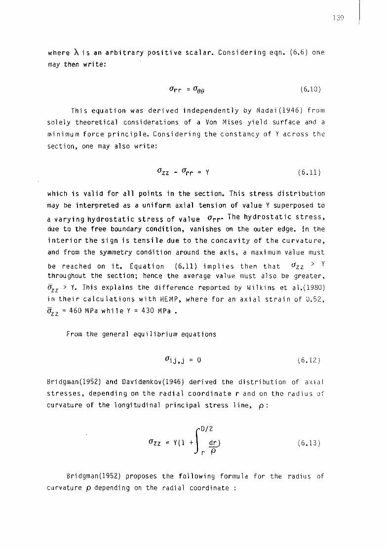
where X i s an a r b i t r a r y p o s i t i v e sca la r . Cons ider ing eqn. (6.6) one
may then wr i t e :
<7rr =Gee (6.10)
This equat ion was der ived independent ly by Nadai(1946) from
solely theoret ica l considerations of a Von Mises y i e l d surface and a
minimum fo rce p r i n c i p l e . Consider ing the constancy of Y across the
sect ion, one may also w r i t e :
Ozz _ Crr = Y (6 .11)
which is va l i d for a l l points in the sect ion. This stress d i s t r i b u t i o n
may be interpreted as a uniform axial tension of value Y superposed to
a va ry ing h y d r o s t a t i c s t ress of value ° > r T h e h y d r o s t a t i c s t r e s s ,
due to the free boundary condi t ion, vanishes on the outer edge. In the
i n t e r i o r the sign i s t e n s i l e due to the concav i t y of the c u r v a t u r e ,
and from the symmetry condit ion around the axis , a maximum value must
be reached on i t . Equation (6.11) i m p l i e s then t h a t ^zz > Y
throughout the sect ion; hence the average value must also be greater,
azz > Y. This explains the di f ference reported by Wilkins et al.(1980)
in t h e i r c a l c u l a t i o n s w i t h HEMP, where f o r an ax ia l s t r a i n of 0.52,
Ozz = 460 MPa w h i l e Y = 430 MPa .
From the general equi l ibr ium equations
a i j , j = 0 (6 .12)
Bridgman(1952) and Davidenkov(1946) derived the d i s t r i b u t i o n of axial
s t resses , depending on the r ad i a l coord ina te r and on the radius of
curvature of the longi tudinal pr inc ipal stress l i n e , p :
fD/2
tfzz = Y(l +1 dr.) (6 .13) J v P
Bridgman(1952) proposes the fo l low ing formula for the radius of
curvature p depending on the radial coordinate :
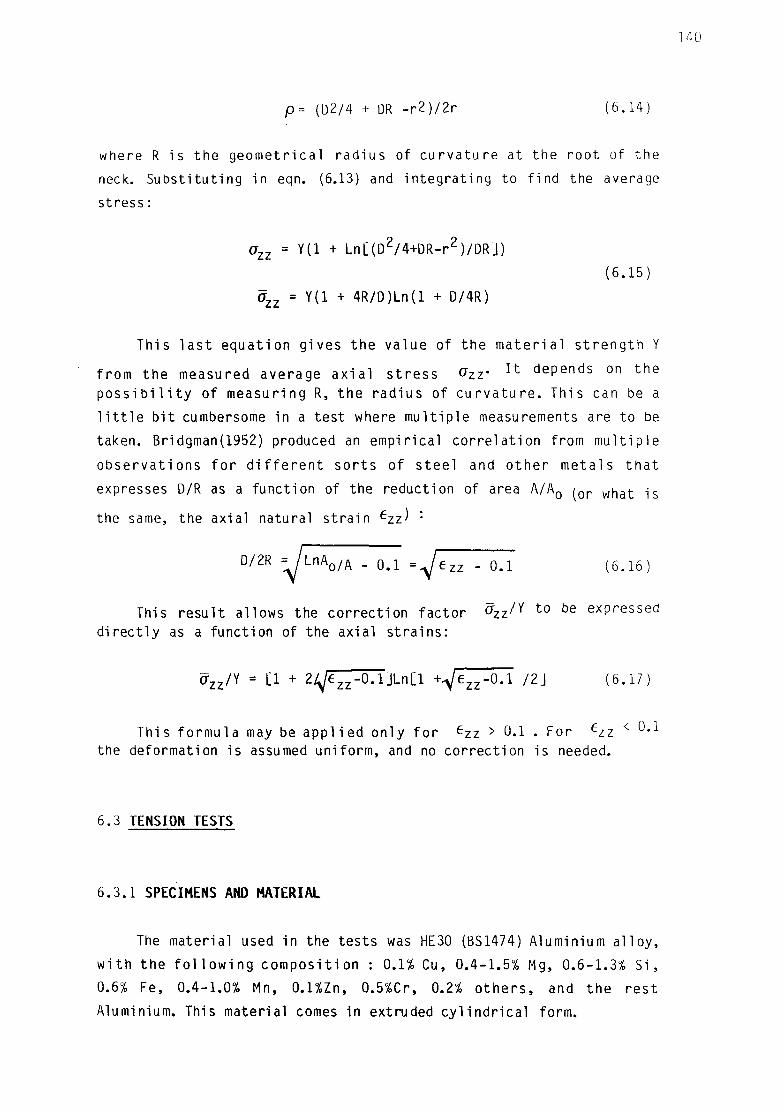
p = (D2/4 + OR - r 2 ) / 2 r (6 .14)
where R is the geometr ica l radius of cu rva tu re at the root of the
neck. Subst i tut ing in eqn. (6.13) and in tegra t ing to f ind the average
stress:
°zz = Y ^ + Ln[(D2/4+DR-r2)/DRj)
(6.15)
azz = Y(l + 4R/D)Ln(l + D/4R)
This l a s t equat ion gives the value of the ma te r i a l s t r eng th Y
from the measured average a x i a l s t ress ^zz* ^ d e P e n d s o n t n e
p o s s i b i l i t y of measuring R, the radius of c u r v a t u r e . This can be a
l i t t l e b i t cumbersome in a test where mul t ip le measurements are to be
taken. Bridgman(1952) produced an empir ical cor re la t ion from mul t ip le
observat ions f o r d i f f e r e n t so r t s of s tee l and o ther metals t h a t
expresses D/R as a funct ion of the reduction of area A/A0 / o r w n a t ^s
the same, the axial natural s t ra in ezz ' :
D/2R = / L n A o / A . QA =^ezz - 0.1 (6.16)
This resul t allows the correct ion factor ^ z z ^ t 0 t )e e x P r e s s e d
d i rec t l y as a funct ion of the axial s t ra ins :
az z /Y = [1 + 2^e z z -0 .1 ]Ln[ l + ^ e z z - 0 . 1 /2J (6.17)
This formula may be app l i ed only f o r ezz > 0«1 • For ezz < u , i
the deformation is assumed uni form, and no correct ion is needed.
6.3 TENSION TESTS
6.3.1 SPECIMENS AND MATERIAL
The material used in the tests was HE30 (BS1474) Aluminium a l loy ,
w i t h the f o l l o w i n g compos i t ion : 0.1% Cu, 0.4-1.5% Mg, 0.6-1.3% S i ,
0.6% Fe, 0.4-1.0% Mn, 0.1%Zn, 0.5%Cr, 0.2% o t h e r s , and the res t
Aluminium. This material comes in extruded cy l i nd r i ca l form.

141
Mechanical propert ies in the as-received condit ion were obtained
from the manufacturers:
0.1% proof stress 239 - 270 MPa
density 2700 Kg/m3
Young's modulus, E 67000 MPa
Poisson's r a t i o , v 0.3
Ultimate tens i le strength 278-293 MPa
Elongation on 2 in 7 - 10%
This ma te r i a l was cut and machined to form specimens of the
geometry descr ibed in f i g u r e 6.2 . A s l i g h t taper was given in order
to control the necking pos i t i on , the smallest diameter being located
at the mid-sect ion.
The composition and treatment of HE30 Aluminium is ident ica l to
the HT30 Aluminium tube material employed in the tube crumpling tes ts .
The only d i f f e r e n c e l i e s in the fo rm ing processes (ex t rus ion or
drawing) . As a r e s u l t , mechanical p r o p e r t i e s f o r both m a t e r i a l s are
very s i m i l a r . The small d i f f e r e n c e was assumed to vanish in the
annealing process to which both specimen types were subjected (sect.
7 .3 .2 .1) .
6 . 3 . 2 PROGRAMME
The specimens were annealed at 350oc pr io r to tes t i ng . Six tests
in a l l were performed wi th the fo l lowing annealing t imes:
Test Annealing time, hours
CTl CT2
CT3
CT4
CT5
CT6
5 7
none
3
5
5

142
After annealing, all specimens were oven cooled.
6.3.3 PROCEDURE
The tests were carr ied out using an INSTRON Model 1195 machine,
w i t h a lOOkN load c e l l . The specimens were secured w i t h t r a n s v e r s a l
12.9 mm diameter s tee l pins to a f i x e d crosshead at one end and a
moving crosshead at the opposite end. The load was applied w i th stroke
con t ro l , at crosshead ve loc i t ies of between 0.5 and 1.0 mm/min , up to
specimen f r a c t u r e . Frequent measurements of the neck d iameter were
taken wi th a Vernier ca l iper (precision ±;o,o5 mm).
6.3.4 RESULTS
The r e s u l t s of the t e s t s are summarized in f i g u r e s 6.3 and 6.4.
Figure 6.3 shows the axial load against the axial s t ra in ezz a t t h e
minimum neck s e c t i o n . In a l l the t e s t s a peak value of the load is
reached when the necking i n s t a b i l i t y ar ises. Al l specimens show f a i r l y
close results except CT3, which was not annealed. CT3 shows an ea r l i e r
onset of neck ing , at around e z z=0.07, a n d m u c h n i 9 h e r l e v e l s o f
loads, wi th peak value 57kN. This corresponds to a strength of 285MPa
referred to the or ig ina l cross-sect ional area, in accordance wi th the
manufacturer's speci f icat ions (sect. 6.3.1). The non-annealed CT3 tes t
showed a lso cons iderab ly l e s s d u c t i l i t y (max. n a t u r a l s t r a i n
ezz=0.70).
Results for the remaining tests all lie within a narrow band;
peak loads range between 21 and 25kN, onset of necking between
ezz=0.15 - 0.20 , and maximum strains before fracture between
e z z = 1.15 - 1.25 . Differences in annealing time clearly did not
influence the behaviour beyond experimental uncertainty. For instance,
specimens CT5 and CT6 were annealed for longer time (5 hrs) than CT4
(3 hrs), yet they yield results which are slightly closer to the non
annealed CT3. These differences must be attributed to experimental
scatter. The annealing process may be assumed complete for all
specimens except CT3.

00
00
00
00
00
00
9
00
0 0
0 0
0
0
0
0 - f racture
1 s v, 'A V,
A ^ ^ A v AV
A ^
° CT3 (non-annealed)
o CTA • CT5 * CT6
A
V
J_
0.00 0.20 0.40 0.60 0.80 1.00 1.20
N a t u r a l S t r a i n , ezz
F i g u r e 6.3s TENSION TESTS - AXIAL LOAD VS. STRA

In f i g u r e 6.4 the average ax ia l s t ress at the neck is p l o t t e d
against the ax ia l s t r a i n f o r the annealed specimens. Although the
t o t a l load drops a f t e r the onset of necking due to the geomet r ica l
reduct ion in area, i t may be seen t h a t at the e lementary l eve l the
material does not cease to harden.
Frac ture occurred w i t h d u c t i l e cup-and-cone geometries for a l l
the annealed specimens. A r e p r e s e n t a t i v e p i c t u r e of one of the
f r a c t u r e d specimens i s given in f i g u r e 6.5 . For the non-annealed
specimen CT3 f r a c t u r e was more b r i t t l e and occurred e a r l i e r w i t h a
bang, producing a much less well developed neck ( f i g . 6.6).
Judging from these resul ts i t was concluded that completion of
the anneal ing process was reached f o r CTl , CT2, CT4, CT5 and CT6
specimens. The mechanical propert ies derived from each of the tests
may be averaged in order to ob ta in r e p r e s e n t a t i v e p r o p e r t i e s f o r
annealed HE30 aluminium a l loy .
6.3.5 MICROHARDNESS MEASUREMENTS
The necked bars were employed to study the d i s t r i b u t i o n of
p l a s t i c s t r a i n s across t r ansve rsa l sec t i ons . This was done through
microhardness measurements performed in a section normal to the axis
of one of the tens i le specimens a f te r f rac ture . This section was the
nearest to the f r a c t u r e zone which d id not show v i s i b l e voids or
change t o i t s s t r u c t u r e f r om the f r a c t u r e . A f t e r p o l i s h i n g ,
microhardness indentations were performed at several locat ions along
two normal r a d i i . Fur ther d e t a i l s of the microhardness t e s t i n g
procedure and equipment are given in sec t ion 7.3.1.3.1. The r e s u l t s
are shown in t a b l e 6 . 1 ; they show no s i g n i f i c a n t v a r i a t i o n of the
hardness accross the sect ion.
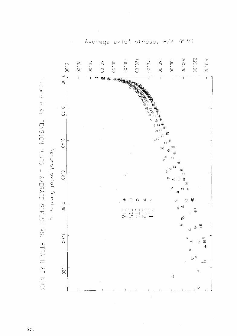
A veraqe ax >g< ial stress, P/A (MPa)
o
o o
o
CD
o
4> O
O O
o o o o
CO
o o o
o o CD
o
o
o CD
o
o o
o o o o
CO
o CD CD
20
0.
CD
o
220.
CD
o
o
o o
o o
IV)
o
4>
o
o
o CD
O
CO
o
o o
<a o t>
• > <c o
*
913
• o <a t>
n n o o — i — i — i — i ui -i> rv) —
> •
Q *
<
> o
>< c
0 Q
t>
<1 O
< Q •
iv) o
£> O
#o
[>

1 2 -f§
1 1 -|§
-10—g
9 -g
8 -g
7 -g
6 -H
4 -=:
1 -= Mode m
: ng land c O
igure 6.5: CT4 tensile specimen after fracture Figure 6.6: CT3

147
Point
1
2
3
4
5
6
7
Indentation Diagonal
(Microns)
53
53
54
52
52
53
53
Microhardness
Hm(Kg/mm2)
64
64
63
66
66
64
65
I •' 5 6 7 *r
Current diameter
D = 9.2mm
Original diameter
Do = 15.9mm Microhardness load
P = 99g
ezz=-2Ln(D/Do) = 1 - n
Tab! e 6 .1 : Microhardness measurementes in neck sec t i on of t e n s i l e
specimen CT4.
From simple cons ide ra t i ons of p l a s t i c i t y theory ( H i l l (1950),
p.254), the hardness value H can be related l i nea r l y to the material
s t rength Y, i t s e l f funct ion of the p las t ic s t ra in e
H = CY( ep )
C being a constant whose value l i e s between 2.5 and 3.0 . Hence these
microhardness results support the assumption of constancy of Y and e
across the minimum neck section (sect. 6.2.1).
6.4 MATERIAL HARDENING LAW
For aluminium power laws of the type
a= A e' (6.18)
where: a uniaxial true stress
e uniaxial natural s t ra in
A,n material constants

148
f i t the ma te r i a l behaviour very w e l l . The parameters A,n have a
physical i n te rp re ta t i on : A equals the stress for un i t s t r a i n , and i t
can be shown tha t n corresponds to the s t r a i n at the peak load in a
tens i le t e s t .
Given the equivalence between the uniaxia l stress and equivalent
s t ress po in ted out i n eqn. (6.5), a convenient and general form of
expressing the material behaviour is
Y = A( e z z ) n = A( €p+Y/E)n ? Ae£ (6.19)
Y/E represents the e las t i c part of the s t ra ins ; these are usual ly very
small compared to the p las t ic par t , ep>
The average ax ia l s t ress data presented in f i g u r e 6.4 were
co r rec ted w i t h formula (6.17) to ob ta in the values f o r the m a t e r i a l
s t r e n g t h , Y. A power law Y = A( e z z ) n was then f i t t e d to the data
from each tes t , by performing a l inear regression in the logar i thmic
values (table 6.2). The parameters A,n so obtained for each test were
averaged y i e l d i n g mean va lues of A = 181.7 MPa, n=0.182; these
parameters prov ide a reasonable f i r s t es t ima te f o r the m a t e r i a l
hardening law.
Test
CTl
CT2
CT4
CT5
CT6
Average
A (MPa)
169.1
172.5
184.7
191.5
190.6
181.7
n
0.190
0.177
0.196
0.170
0.178
0.182
Table 6.2: Results of power law f i t s to tension test resul ts

149
The r e s u l t s of t h i s average f i t , toge ther w i t h the equ i va len t
stress - s t ra in data derived from experiment, are p lo t ted in f igure
6.7 . Comparing w i t h the average ax ia l s t resses in f i g u r e 6.4 the
i n f l uence of the c o r r e c t i o n fo rmula (6.17) i s pa ten t , l o w e r i n g
cons iderab ly the s t ress values f o r the l a r g e r s t r a i n s . For a u n i t
s t r a i n , the average axial stress is approximately 215 MPa, whi le the
equivalent stress is lowered to 182 MPa , a reduction of 18%.
Although the "average" power law obta ined represents a good
ove ra l l f i t , i t can be seen in f i g u r e 6.7 t h a t some d isc repanc ies
s t i l l e x i s t i n the region of low s t r a i n s ( ezz < 0> 2)> w h i l e t n e f i t i s very good f o r the h igher s t r a i n s . I t can a lso be seen t h a t the
discontinuous appl icat ion of the correct ion formula (6.17) from ezz >
0.1 has produced a d i s c o n t i n u i t y in the slope of the s t ress - s t r a i n
data.
I t i s reasonable to suspect t h a t the c r i t i c a l reg ion f o r
a p p l i c a t i o n of the c o r r e c t i o n fo rmula (6.17) i s i n the low s t r a i n
region, before the necking or when the neck curvature is smal l . I t is
here that the empir ical re lat ionship (6.16) between the neck curvature
and the ax ia l s t r a i n may be more in e r r o r . This r e l a t i o n s h i p has a
bias towards s t e e l , which u s u a l l y necks e a r l i e r than a lumin ium.
Greater conf idence can be placed in eqn. (6.16) f o r the h igher
s t ra ins , where the necking is well developed.
Consequen t l y two a d d i t i o n a l c u r v e f i t s to the co r rec ted
exper imenta l data have been t r i e d . These ma in ta in roughly the same
s t ress values f o r the h igher s t r a i n s , but d i f f e r s l i g h t l y from the
average curve f i t for the lower s t a i n region. A simple way for th i s
v a r i a t i o n i s , ma in ta in ing the power law approach, to keep the same
value for parameter A (which represents the stress for un i t s t r a i n ) ,
and vary the exponent n. Two addit ional values of n were t r i e d :
n l = 0.159 which gives a curve i n the middle of the s t ress
band, for ezz < Q.2 n2 = 0.133 which gives a curve near the top of the s t ress
band, fo r ezz < ^«2
appears that n 1 Shou1d give the best fit, but this will be
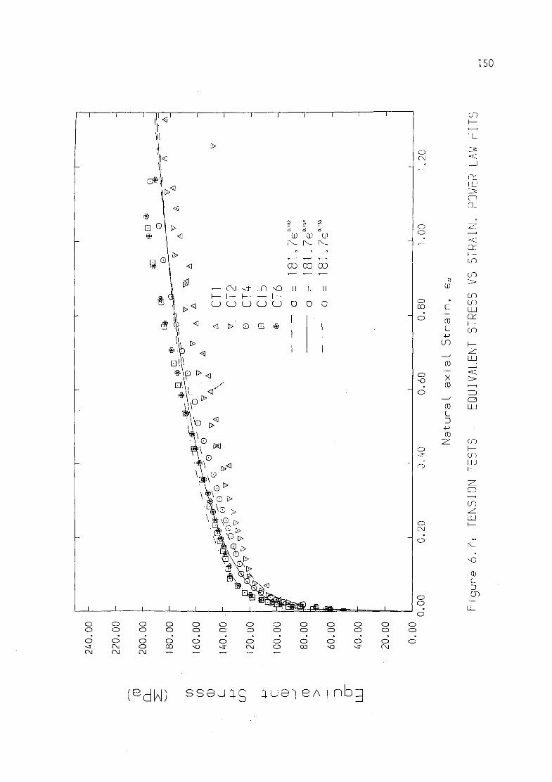
150
I M I
II
-e*l
# 1 <
1 D>
s 0 < \ 0 1 ^ — c\i <r un -o
#, a i— h- h- i— i— H ] <g U U U U U I S § ^ <a > O • *
• • P <|
*\P > <
•V- > <
\ib ><3
1 ° «
\ t o t >
' i * G £>
i i i i i i i ^ ^
i
S £ d c>
CO Ci)
» 0 0 CO
II
o
1 1 1
1
II
0
1 1
°o
» 00
II
o
1
1
1
_
-
-
-
1
o o o -3"
o o o CM CM
o o o o CM
O O
O QO
O O
O SO
O O
o
o o
o CM
o o o o
o o
o 00
o o
o SO
o o
o -4"
o o o CM
o CM
o o
o 00
o SO o
o
o
o CM o
o o
o o o
e^^j) s s e j u g aue] BA ! nbg

151
decided from the r e s u l t s of numerical c a l c u l a t i o n s us ing the th ree
suggested curve f i t s , and t h e i r comparison w i t h exper imenta l
observation.
6.5 NUMERICAL CALCULATIONS FOR TENSION TESTS
The tension tests were simulated numerical ly. From the resul ts of
the calculat ions i t was possible to decide on the power law parameters
that provide the best f i t fo r the experimental resu l ts . Add i t i ona l l y ,
the calculat ions provided a check for the v a l i d i t y of the assumptions
t h a t were made i n the i n t e r p r e t a t i o n of the t e n s i l e t e s t f o r the
stress and s t ra in d i s t r i bu t i ons . F ina l ly th i s exercise was useful as a
va l idat ion of the Exp l i c i t F in i t e Difference model proposed in th i s
t h e s i s ( c h a p t e r 4 ) , when a p p l i e d t o l a r g e s c a l e n o n - l i n e a r
computations for pract ica l engineering problems.
6.5.1 MODEL
The calculat ions were performed using axisymmetric analysis, wi th
a 2-D d i s c r e t i z a t i o n in the r-z plane ( f i g . 6.8). The symmetry
condit ion around the plane of the minimum cross-sect ion (z=0) allowed
a f u r t h e r reduc t ion to a quar te r of the r - z s e c t i o n . The mesh
consisted of 875 t r iangu lar c e l l s , grouped in to 438 MTQ elements (see
sect. 4.2.2) and 390 nodes. The model did not comprise the end f i x ings
as they l i e f a r from the area of i n t e r e s t and i t was considered t ha t
they behave in pract ice as r i g i d load- t ransmi t t ing devices. Only the
cen t ra l tapered po r t i on of h a l f - l e n g t h 37.5 mm was model led. Shear-
f ree boundary cond i t i ons were assumed at the top and bottom ends of
the specimen modelled. The mesh becomes progressively f i ne r near the
neck reg ion , which i s the area of i n t e r e s t , and where the s t ress and
s t r a i n g rad ien ts w i l l be s teepest . A d d i t i o n a l l y , a high r:z aspect
r a t i o was given to the elements in t h i s area in order to avoid
excessively d is tor ted shapes when the neck is elongated in the axial
d i rec t i on .

152
? * * S.I mm Axis of symmetry.,
top section-(prescribed motion]'
bottom section_ (fixed)
1 ,
37.5 mm
795mm.
Figure 6.8. MESH USED FOR TENSION TEST CALCULATIONS
12
10
6 -
TENS5 TENS7 TENS3
0.00 0.20 0.40 .0.60 0.80 1.00 1.20 1.40 1.60
T I me (msec)
Figure 6.9, HISTORIES OF VELOCITY APPLIED AT END OF NUMERICAL MODEL
153
6.5.2 ANALYSIS
The tests were performed under quas i -s ta t ic condit ions at speeds
of between 0.5 - 1.0 mm/min. The numerical algori thm used solves the
equations of cont inuum mechanics in t ime w i t h an e x p l i c i t t i m e -
marching scheme; t h i s leaves no op t ion f o r s t a t i c a n a l y s i s , as
c a l c u l a t i o n s r e p r e s e n t a lways a f u l l dynamic mode l . As t h e
computational t ime-step is l i m i t e d for numerical s t a b i l i t y to a small
value (sect . 4.7), i t would be too expensive in computer t ime to
perform the dynamic analysis in real t ime.
To be able to perform the c a l c u l a t i o n s v e l o c i t y s c a l i n g was
in t roduced (see sec t ions 4 . 1 , 5.4). The v e l o c i t y of de fo rmat ion was
increased in order to bring down the number of computational cycles
necessary f o r the a n a l y s i s , from the 2x10¹⁰ t h a t would be needed i f
the real ve loc i ty of deformation were to be used, to around 4x10⁴.
Velocity scal ing usually works well fo r quas i -s ta t ic problems, as
long as the deformat ion is app l ied s l ow l y enough so as to l e t the
stress-waves t r a v e l back and f o r t h along the model several t i m e s ,
al lowing red is t r i bu t i on of stresses. In other words, the model must
not depart too much from the s t a t i c e q u i l i b r i u m which must be
simulated at each step in t ime. Two ways of quant i fy ing th i s departure
from equi l ib r ium are:
- Ensuring t h a t the load h i s t o r i e s at opposi te ends of the specimen
are approximately equal (the out of balance forces must be small when
compared to the to ta l forces);
- Checking t ha t the k i n e t i c energy is smal l compared to the o v e r a l l
energy involved in the deformation process.
Three calculat ions are reported here, for each of the power law
curve f i t s f o r the ma te r i a l c o n s t i t u t i v e behaviour suggested in
sec t ion 6.4 (eqn. 6.18):

Y = A e n
Analysis
TENS3
TENS5
TENS7
A (MPa)
181.7
181.7
181.7
n
0.182
0.159
0.133
In t h e c a l c u l a t i o n s t h e t y p i c a l a x i a l v e l o c i t y was 10 m/s and
t o t a l t imes of ana l ys i s were between 1.25 msec and 1.6 msec.
The neck sec t ion was kept f i x e d in i t s plane w h i l e a p rescr ibed
v e l o c i t y was a p p l i e d t o t h e upper end ( f i g . 6 .8) . The h i s t o r i e s o f
app l ied v e l o c i t i e s are given in f i g u r e 6.9 . Ramps were in t roduced t o
a v o i d sudden changes c a u s i n g a l t e r a t i o n s t o t h e e q u i l i b r i u m .
Cons ider ing the s t ress-wave propagat ion v e l o c i t y in Aluminium of 6000
m/s and an i n i t i a l length of 37.5 mm , the l a rges t s t ress-wave per iod
i s ( i n i t i a l l y ) 0.0125 msec . Thus the number of s t ress-wave per iods in
t h e c a l c u l a t i o n s , or i n o t h e r w o r d s , t h e number of t i m e s t h e s t r e s s
waves t r a v e l l e d back and f o r t h r e d i s t r i b u t i n g s t r esses , i s between 100
and 128. We s h a l l see l a t e r ( s e c t . 6.5.3) t h a t t h e d e p a r t u r e f r o m
e q u i l i b r i u m i n the fo rce h i s t o r i e s t h i s amount of v e l o c i t y sca l i ng
ocassioned was s m a l l .
The importance of t h i s c o s t - c u t t i n g compromise w i l l be c l e a r by
ment ion ing t h a t CPU t ime f o r each of the c a l c u l a t i o n s in a CRAY-IS was
between 30 and 45 m i n u t e s . Th i s r e p r e s e n t s c o n s i d e r a b l e compu te r
r e s o u r c e s . In a model w i t h o u t v e l o c i t y s c a l i n g t h e c o s t s wou ld be
5x10⁵ t imes h igher (tens of years CPU t i m e ) , way beyond the f e a s i b l e
range w i t h the cu r ren t development in d i g i t a l computers.
6 .5 .3 RESULTS
The average s t res versus s t r a i n r e s u l t s ( f i g . 6.10) l i e p r e c i s e l y
where i t was presumed f r o m t h e c h o i c e o f c u r v e f i t s done i n s e c t i o n
6.4 . In a l l t h r e e cases f o r t h e l a r g e s t r a i n r e g i o n ( e z z > Q . 2 ) t he
f i t i s very good, in the midd le of the exper imenta l band. For the low
s t r a i n r e g i o n ( e z z < Q . 2 ) t h e r e s u l t s f r om TENS3 are i n the l o w e r
p a r t of t h e band, TENS5 i n t h e m i d d l e , and TENS7 i n t h e upper p a r t .

(V. OD
— r\j -<i- i_n o I— I— t— I— H-u u u u u i — i — i — i — i —
z -z. z z z LU LU LU LU LU
cz cz cz cz cz LU LU LU LU LU CL CL Q_ Q_ CL X X X X X LU LU LU LU LU
<\ t> O LU
o o
24
0
o CD
O
o o o o
o o o CO
o o o
o o o
o o o
o o o o
o o o CO
o o o
o o o
o o o f \ l
o o o
;dU) V/d "ssajug ]ejxe ebejaAy

26.00
24.00
22.00
20.00
18.00
16.00
14.00
12.00
10.00
8.00
6.00
4.00
2.00
0.00
3
\-
CALCULATION (TENS3) — CALCULATION (TENS5)
- • - CALCULATION (TENS7)
A EXPERIMENT (CT1) v EXPERIMENT (CT2) G EXPERIMENT (CT4) 0 EXPERIMENT (CT5) * EXPERIMENT (CT6)
0.00 0.20 0.40 0.60
N a t u r a l a x i a l S
F i g u r e 6.11s TENSION TEST CALCULATI

157
Th is suggests t h a t t h e cu rve f i t used f o r TENS5 i s t h e most
appropriate, as had been ant ic ipated. Hence, the hardening law for the
HE30 aluminium material w i l l be taken as:
Y = 181.7 e 0 * 1 5 9 (MPa) (6.20)
A view of the deformed mesh for TENS5 with all symmetries plotted is given in figure 6.12. At this point the axial strain at the neck
was ezz = *••" *
The curves presented in f igures 6.10 and 6.11 were taken from the
calculated t ime-h i s to r i es , a f te r averaging the load between top and
bottom of the model, and having app l i ed a numer ical f i l t e r w i t h a
centred moving average technique, to f a c i l i t a t e the v i sua l i za t ion and
in te rp re ta t i on . The exact t ime-h is to r ies obtained in the ca lcu lat ions
f o r top and bottom loads are given i n f i g u r e 6.13 . I t can be seen
that a state of s ta t i c equ i l ib r ium existed for most of the analys is,
the two load h i s t o r i e s being approx imate ly equa l . At about 1.1 msec
however, some o s c i l l a t i o n s occur in the h i s t o r i e s c r e a t i n g c e r t a i n
d e p a r t u r e f r o m s t a t i c e q u i l i b r i u m . These o s c i l l a t i o n s have
approximately the period of the longi tudinal stress waves t r a v e l l i n g
along the specimen:
T = 2 L. = 2 45xl0-3m = 0.015 msec c 6000 m/s
L being the cu r ren t leng th of the specimen and c the v e l o c i t y of
s t ress waves. I t can be apprec ia ted t h a t only a smal l number of
s t ress-wave per iods occur in an i n t e r v a l of t ime at which la rge
var iat ions in the neck size (see f igure 6.14) and material behaviour
take p lace. The model does not have t ime to d iges t these changes
quickly enough and the information is t ransmi t ted in jumps o r ig ina t ing
the consequent e l a s t i c o s c i l l a t i o n s . I t i s i n t e r e s t i n g to note the
l a rge r ampl i tude of the o s c i l l a t i o n s at the top end, which i s
unloading e l a s t i c a l l y , than at the neck, where the p l a s t i c i t y of the
material behaviour dampens out the osc i l l a t i ons . At no moment however
do the osc i l l a t i ons in load depart from the equ i l ib r ium value by more
than 10%, and the expected trend of the load curve is maintained.

Ibtf
For details of initial geometry see Figure 6.8
_L —L K 1 /\ f\ /\ r\ I A ^gHIHN^g V-HLLLl — L I j IH pHrtm::"::inhhW
mm l w : : i | |
iBBk | S E E E H E E E | 1
p '
strain at neck e= 1.22
Figure 6.12. DEFORMED MESH FOR A/Ao=0.29
HE30 ANNEALED ALUMINIUM BAR TENSION TEST CALCULATION (TENS5)

26.00
24.00
22.00
20.00
18.00
16'. 00
14.00
12.00
10.00
8.00
6.00
A.00
2.00
0.00
^ } (' I.
I T " :•;. h i iyn
' ( i
LOAD AT MINIMUM NECK SECTION LOAD AT TOP END OF SPECIMEN
NUMERICAL CALCULATION FOR.TENSION TEST (TENS5) HE30 ANNEALED ALUMINIUM BARS
7 ' ,i
0.00 0.20 0.40 1.00 1.20 0.60 0.80
T 1 me (msec)
Figure 6.13= CALCULATED LOAD HISTORIES WITHOUT FILTERING
8.00
7.50
7.00
6.50
6.00
5.50
5.00
4.50
0.60 0.80
T i me (msec)
1.20
Figure 6.14: HISTORY OF NECK RADIUS

For f i g u r e s 6.10 and 6.11 the load h i s t o r i e s were averaged and
f i l t e r e d , removing osc i l l a t i ons of frequencies higher than 50000 Hz,
which corresponds roughly to the stress-wave period. In t h i s way the
ove ra l l t r end of the r e s u l t s can be seen more c l e a r l y , w i t h o u t
unwanted numerical osc i l l a t i ons , due mainly to the compromise made in
the veloc i ty scal ing.
Some contour p l o t s of d i f f e r e n t s t ress components f o r the neck
region are presented in f i gu re 6.15; the fo l l ow ing observations may be
made about these:
a) The r a d i a l ( f i g . 6.15b) and hoop ( f i g . 6.15c )• s t r e s s e s are
approximately equal in the neck region, tending to zero at the outside
edge, and reaching maximum values near the axis of about 60 MPa;
b) The a x i a l s t ress ( f i g . 6.15d) i s c l e a r l y non-un i fo rm across the
neck s e c t i o n , decreasing from approx. 270 Mpa in the ax is to 200 MPa
on the outside;
c) The y i e l d s t reng th Y (eqn. 6.2) i s roughly un i fo rm across the neck
section ( f i g . 6.15a), wi th an approximate value of 189 MPa;
d) The axial s t ra in at the minimum section is e z z = i#22 which from
eqn. (6.20) corresponds to a f low stress of
Y = 181.7xl.220 '159 = 188 MPa
and an average axial stress (from eqn. (6.17)) of
<7ZZ = Y(l+2//T7l2)Ln(l+lfr7l2'/2) = 1.23Y = 231 Mpa
These values correspond very c l o s e l y to those expressed above in c)
and b) respect ively.
The y i e l d strength contours for the complete specimen are p lo t ted
in f i g u r e 6.16, showing the much lower l e v e l s of s t r a i n - h a r d e n i n g
which occurred in the upper par t of the model. This hardening
happenned in the f i r s t stage of uniform deformation of the specimen;
af ter the necking that region has been unloading e l a s t i c a l l y .

:"155:"MPlV"-
T
"165-fiPa-:-....
17.5 MPa'"7""
185 lip'a";
- i -^ WPT'-yr-
1 ^ J: •: 40 MPa
a) Yield Strength Y b) Radial Stress (j^
.MPa
feO...MJ
4'0-MPa
• " " ' [ " ( • ' ) " ! ' "[•' " V ' • - ; \ - - - : - ••••;.........
/ 12tfMPa/ / " '"'•'.•••-/••lBOMPa
c) Circumferential Stress On d) Axial Stress (jr.
Figure 6.15: Tension test calculations - Stress contours in neck region

: r
16:
• H -
:/.140(JMEa.:.
\. •V.
. l i . 1 . 3 0 . . ^ . .
: ( • • • : •
\ :
.\l4Q:MEa.
: ~ T " 1 4 0 JTP&
!^}.'lSQ.:.Mp.a....:..
•••••;i-50.;MP^:
:r6;Q;-^p'a
: ^ 7 P ^ P M P £
Figure 6.16: Tension t e s t c a l c u l a t i o n s - y i e l d strength (Y) contours (general view)

163
A l l t h e s e r e s u l t s match very c l o s e l y t h e t h e o r e t i c a l
i n t e r p r e t a t i o n of the t e n s i l e t e s t d e t a i l e d in 6.2, suggest ing the
general v a l i d i t y of that in te rp re ta t ion and of the numerical model.
6.6 CONCLUSIONS
1. Tension t e s t s on c y l i n d r i c a l bars c o n s t i t u t e a s imple and
r e l i a b l e means of o b t a i n i n g m a t e r i a l s t r e s s / s t r a i n data at l a rge
s t ra ins , when viewed as a 3-D p l a s t i c i t y problem.
2. The i n t e r p l a y between the theory (sect . 6.2) and numer ica l
ana lys i s (sec t . 6.5), coupled w i t h exper imenta l f a c t (sec t . 6.3),
a l lowed a s imple and rep resen ta t i ve c o n s t i t u t i v e law f o r the HE30
Aluminium to be es tab l i shed (eqns. 6.18, 6.20), f o r use in f u t u r e
la rge s t r a i n p l a s t i c i t y analyses (chapter 7). This c o n s t i t u t i v e law
assumes Von Mises p l a s t i c i t y wi th power law isot rop ic hardening.
3. Excellent agreement was achieved between numerical pred ic t ions,
experimental f a c t , and theoret ica l understanding, of the behaviour of
a p l a s t i c a l l y deforming necked cy l i nd r i ca l bar (sections 6.3.5, 6.5.3,
f i g s . 6.10, 6 .11, 6.15). The semi -empi r i c a l t h e o r i e s of Bridgman
(1952) and Davidenkov and Spir idinova (1946) were broadly confirmed by
the numerical resu l t s .

CHAPTER 7
CONCERTINA TUBE COLLAPSE ANALYSIS
7.1 INTRODUCTION
7.1.1 Scope
7.2 OVERVIEW OF ENERGY DISSIPATING DEVICES
7.2.1 Definition and criteria
7.2.2 Types of energy dissipating devices
7.2.3 Tubes as energy absorbers
7.2.3.1 Lateral compression
7.2.3.2 Axisymmetric axial crumpling
7.2.3.3 Diamond-fold axial crumpling
7.2.3.4 Tube inversion
7.2.4 Methods of analysis
7.3 QUASI-STATIC CONCERTINA TUBE COLLAPSE MECHANISMS
7.3.1 Related experimental work
7.3.1.1 Experimental Programme and method
7.3.1.2 Typical experimental results
7.3.1.3 Microhardness tests
7.3.1.3.1 Equipment and procedure
7.3.1.3.2 Derivation of material strength, Y
7.3.2 Numerical model
7.3.2.1 Discretization and material
7.3.2.2 Velocity scaling
7.3.2.3 Interpretation of output
7.3.3 Results from numerical calculations and experiment
7.3.3.1 Tube geometry A: ID=19.05mm, t=1.64mm, L=50.8mm
7.3.3.2 Tube geometry B: ID=19.05mm, t=1.17mm, L=50.8mm

7.3.3.3 Tube geometry C: 0D=38.1mm, t=1.65mm, L=50.8mm
7.3.3.4 Tube geometry D: 0D=25.4mm, t=0.95mm, L=25.4mm
7.3.4 Parametric studies in numerical analyses
7.3.4.1 Influence of friction
7.3.4.2 Influence of velocity scaling
7.3.4.3 Influence of mesh refinement
7.3.4.4 Influence of element type
7.3.5 Discussion
7.4 MEDIUM VELOCITY (176m/s) TUBE IMPACT ANALYSIS
7.4.1 Description of problem
7.4.2 Numerical idealization
7.4.3 Numerical results
7.4.4 Discussion
7.5 CONCLUSIONS
7.1 INTRODUCTION
The numerical methods described in chapter 4 are applied here to
the ana lys is of tube co l l apse mechanisms, w i t h a view to s tudy ing
the i r performance as energy d iss ipat ing devices.
In accordance wi th the charac ter is t i cs of the computer program,
the a t t e n t i o n was r e s t r i c t e d to mechanisms which could be s tud ied
through axisymmetric or 2-dimensional models. In pa r t i cu la r , most of
the work r e l a t e s to a x i a l co l l apse of tubes through ax isymmet r ic
sequential fo ld ing . This mode of col lapse plays an important role in
energy d iss ipat ion and i t s numerical modelling poses some in te res t ing
challenges. For example:
a) Large strains (with values higher than 1.3) and gross deformations
(complete c rumpl ing of tube w a l l s ) need a c a r e f u l and c o n s i s t e n t
mathematical treatment (chapter 2);
b) The need to provide c o n s t i t u t i v e laws v a l i d f o r la rge s t r a i n s
(chapter 6 ) ;
c) Contacts w i t h the p la tens and between f o l d s make necessary a
general logic for in terac t ion between cont inua;
d) Dynamic analysis is necessary, as energy d iss ipat ion occurs mainly
in impact s i tua t ions , where stress-wave propagation or i ne r t i a ef fects
are often important;
e) L a s t l y , a r o b u s t n u m e r i c a l a l g o r i t h m is necessary which
accomodates the s o l u t i o n to the above problems and works we l l in
pract ice for rea l , engineering scale problems (chapter 4).
7.1.1 SCOPE
This chapter relates to the fo l low ing :
1 - F i r s t l y a general overview of energy d iss ipa t ion , and the role of
tubes in i t , i s presented. This i s f o l l o w e d by a d e s c r i p t i o n of some

167
experimental work on tube col lapse; most of t h i s work was car r ied out
by Ghani (1982), and i t w i l l be used to compare w i t h the numer ica l
predict ions for axisymmetric tube crumpling that fo l l ow.
2- Results f rom numerical c a l c u l a t i o n s of q u a s i - s t a t i c ax ia l
co l l apse are given f o r 4 d i f f e r e n t tube geometr ies ( t ab le 7.3). Over
20 computer analyses (table 7.4) were performed in order to assess the
a p p l i c a b i l i t y of the method, and eva luate the i n f l u e n c e of var ious
mode l l ing cho ices . Optimal models were then se lec ted f o r the f i n a l
analyses. The resul ts are compared wi th experimental data.
3- In the medium veloc i ty range, a f u l l - s c a l e model of the impact of
a th in -wa l led vessel at 176 m/s was performed. This problem tested the
performance of the computer code f o r l a rge scale eng ineer ing
computations, involv ing several thousand degrees of freedom and over a
hundred thousand t ime-steps. The resul ts compared well w i th avai lable
exper imenta l data. The c rush ing fo rce obta ined was found t o be
considerably larger than for low-ve loc i ty col lapse.
7.2 OVERVIEW OF ENERGY DISSIPATING DEVICES
Energy d iss ipat ing devices are reviewed b r i e f l y in th i s sect ion.
The in tent ion is to introduce pract ica l project ions for the numerical
a p p l i c a t i o n s presented l a t e r . The importance of the var ious tube
collapse mechanisms is h ighl ighted.
7 .2 .1 DEFINITION AND CRITERIA
Energy d iss ipat ing devices are mechanisms which can dissipate the
k inet ic energy from the impact of c o l l i d i n g bodies in an i r r eve rs ib l e
manner.
E l a s t i c , recoverable systems are t h e r e f o r e excluded from t h i s
d e f i n i t i o n . Usually, energy is dissipated through p las t i c work, being
converted i n t o heat e v e n t u a l l y . To f u l f i l l t h e i r f u n c t i o n w i thou t
excessive deceleration and consequent damage, energy absorbers must
provide a reasonably constant operating force over as long a stroke as

168
possible. This must occur in a cont ro l led ( i .e. without catastrophic
f a i l u re ) and re l iab le way.
I d e a l l y energy absorbers should be made of low cost and w ide l y
avai lable components, w i th high values for the fo l low ing parameters:
- Specific energy, i . e . Energy dissipated / Mass of device
- Stroke e f f i c i ency , i . e . Absorbing length / Total length
- Energy d i s s i p a t i n g d e n s i t y , i . e . Energy d i s s i p a t e d / Volume of
device.
7.2.2 TYPES OF ENERGY DISSIPATING DEVICES
Some of the main types of energy absorbers are summarized below,
concen t ra t i ng on d e s t r u c t i v e (one shot) devices, mainly of meta l l i c
mater ia ls. No attempt is made to provide a comprehensive review of the
t o p i c . Exce l len t reviews have been given by Johnson and Reid (1978)
and Ghani (1982).
Schematically one may c lass i f y the various mechanisms according
to t he i r mode of behaviour, as fo l lows.
a) Ex tens ion . Steel rods or cables under tens ion have been used
ex tens i ve l y in p ipe-wh ip r e s t r a i n t systems (e.g. Hernalsteen and
L e b l o i s , 1976). A disadvantage i s t h a t t e n s i l e de format ions tend to
become local ized in necks and may produce overal l f a i l u r e .
b) Compression. For ins tance the c rush ing of l i g h t w e i g h t c e l l u l a r
bodies or of soft copper bumpers (Hernalsteen and Leblois, 1976).
c) Bending. Beams and plates may dissipate energy through rotat ion in
p las t ic hi.nges. Latera l ly crushed tubes or assemblies thereof provide
some very use fu l devices (Thomas, Reid and Johnson (1976), Sh r i ve ,
Andrews and England (1984)).
d) Compression and bending. Systems in which bending modes are

produced as a resul t of a s t ructura l compression may be included here.
These comprise some of the most e f f i c i e n t energy absorbers, such as
the axial crumpling of c i r cu la r tubes (axisymmetric or diamond modes)
and tube i n v e r s i o n . Tubes w i t h n o n - c i r c u l a r sec t ions have been used
advantageously by Kukkola (1976). Honeycomb panels provide also a very
popular and re l i ab le mechanism (McFarland, 1963).
e) Cyc l i c bending, Here one may inc lude systems such as the r o l l i n g
to rus of Johnson, Reid and Singh (1975). These tend to be assoc ia ted
with l i gh te r operating loads.
7 . 2 . 3 TUBES AS ENERGY ABSORBERS
Tubes have a par t i cu la r in teres t as energy absorbers, because of
a l l the e x i s t i n g devices they present the w ides t range of poss ib le
uses; These inc lude some of the most e f f i c i e n t and r e l i a b l e energy
d iss ipat ion mechanisms.
Tubes are s imple s t r u c t u r e s and t h e r e f o r e cheap and w ide ly
avai lable. Add i t iona l ly , the basic st ructure of many moving vehicles and a i r c r a f t is a tube, which w i l l double up in funct ion as an energy
absorber in the event of a c o l l i s i o n .
The main tube collapse mechanisms are reviewed below. Some simple
c lass ica l analyt ical formulae for co l l apse loads are inc luded where
per t inent .
7.2.3.1 LATERAL COMPRESSION
Tubes crushed l a t e r a l l y provide a very re l i ab le energy absorber
in which the p l a s t i c de fo rmat ion i s concent ra ted around l o c a l i z e d
h i n g e s . DeRuntz and Hodge (1963) s t u d i e d e x p e r i m e n t a l l y and
t h e o r e t i c a l l y t h e i r behaviour , d e r i v i n g a formula f o r the co l l apse
load based on a r i g i d - p l a s t i c , t h i n shel l model:

„ g (4//F) Y t\ (7.1) D^l-(5/D)*
where 6 i s the d isp lacement , t 0 a n d D the th ickness and Diameter of
the tube respect ively, and Y the Yield stress for a per fect ly p las t i c
material model. Due to the absence of material hardening in (7.1) some
d iscrepanc ies w i t h exper iments were no tab le ; Reid and Reddy (1978)
have proposed more recently solut ions in which l inear s t ra in hardening
is considered, achieving better resu l ts .
7.2.3.2 AXISYMMETRIC AXIAL CRUMPLING
When sub jec ted to ax ia l compress ion, tubes may buckle in an
ax isymmetr ic f a s h i o n , fo rming c o n c e r t i n a - t y p e f o l d s which p i l e up
sequential ly on top of each other (Figure 7.1a).
This col lapse mode const i tutes a very e f f i c i e n t energy absorber,
by reason of the gross p l a s t i c de format ions which occur in a la rge
proportion of the tube. The sequential nature of the fo ld ing process
accounts for a reasonably constant operating force over a long stroke.
For given tube dimensions t h i s mechanism is r ep roduc ib l e and very
r e l i a b l e (Ghani, 1982).
Alexander (1960) f i r s t derived an approximate solut ion for th i s
mechanism from r i g i d - p l a s t i c t h i n s h e l l assumpt ions. The average
collapse load and fo ld length according to t h i s theory are
P = 6t0YyDt0 (7.2)
h = / *" ^ 0 (7.3)
Alexander's formulae, however simple, give sensible predict ions
in genera l ; they are o f ten r e f e r r e d to (e.g. Johnson, 1972) and
continue to be used today by many workers (e.g. Hurley, 1983, Mamalis
and Johnson, 1983). However, eqn. (7.2) assumes a per fec t ly p las t i c
ma te r i a l (no harden ing) ; f o r good p r e d i c t i o n s care must be taken to
use a value f o r Y r e p r e s e n t a t i v e of the ac tua l average s t r a i n -

171
hardening of the mater ia l . Experimental and numerical studies car r ied
out here show e f fec t i ve p las t i c s t ra ins accross the fo ld sections of
the crumpled tube between 0.3 and 1.3 (sec t ion 7.3.3). This suggests
an appropr ia te average value of 0.8 s t r a i n t o be used f o r o b t a i n i n g
the value of Y.
Numerical analyses of these mechanisms are undertaken in sections
7.3 and 7.4, cons t i tu t ing the core of t h i s chapter.
7.2.3.3 DIAMOND FOLD AXIAL CRUMPLING
When subjected to ax ia l compression, another possible collapse
mechanism i s the fo rma t ion of non-ax isymmetr ic f o l d s in a diamond
pat tern, accompanied by a change in cross section of the tube ( f igure
7.1b). This mechanism i s a lso r e l i a b l e and e f f i c i e n t as an energy
absorber, although the speci f ic energy is s l i g h t l y lower than for the
concertina mode (Ghani, 1982).
Diamond f o l d c rumpl ing was s tud ied by Pugsley and Macaulay
(1960), who proposed formulae based on r i g i d - p l a s t i c analysis. Further
study has been made by Johnson, Soden and Al-Hassani (1977) who
assumed 'inextensional collapse modes'. Thornton and Magee (1977) have
also used these devices as energy absorbers; they prepared the tubes
p rev ious l y by making 3 c i r c u m f e r e n t i a l i n d e n t a t i o n s at one end, in
order t o avoid the i n i t i a l peak load and t r i g g e r smoothly a 3- lobe
diamond pattern.
7.2.3.4 TUBE INVERSION
Tube inve rs ion modes may be achieved e i t h e r by pushing a tube
a x i a l l y against a radiused d ie or by p re fo rm ing and c lamping
appropriately one end. Inversion may be external or i n te rna l . Plast ic
deformations extend to v i r t u a l l y the complete length of tube, as each
section is f i r s t bent, and then straightened out. An e f f i c i e n t energy
absorber wi th a nearly f l a t load response is thereby obtained.
Guist and Marble (1966) have considered i n v e r s i o n tubes f o r

172
impact absorp t ion in land ing of a i r c r a f t and space v e h i c l e s ; they
proposed a simple r i g i d -p l as t i c equation for the collapse load:
P = 7Tto\/8Dtcr ( 7 - 4 )
Al-Hassani, Johnson and Lowe (1972) have presented a deta i led study of
these devices, developing fu r ther the ana lys i s to i nc lude power- law
s t r a i n - h a r d e n i n g , ach iev ing thus a b e t t e r match to exper imenta l
resu l t s .
7.3 QUASI-STATIC CONCERTINA TUBE COLLAPSE ANALYSIS
7 .3 .1 RELATED EXPERIMENTAL WORK
A d e s c r i p t i o n i s given here of the exper imenta l work on q u a s i -
s ta t i c col lapse of Aluminium tubes to which reference w i l l be made in
the f o l l o w i n g sec t i ons , where the exper imenta l r e s u l t s w i l l be
compared w i t h numerical p r e d i c t i o n s . Most of the exper imenta l data
mentioned here are der ived from work done by Ghani (1982) who
undertook an extens ive programme of study and c l a s s i f i c a t i o n of
co l l apse modes, spanning 189 d i f f e r e n t tube geomet r ies . A good
synopsis of these tests and t h e i r resul ts has been given by Andrews,
England and Ghani (1983).
In addit ion to Ghani's work, 5 extra tubes have been crumpled for
th i s invest igat ion in order to prov ide a d d i t i o n a l exper imenta l data
which were needed (Table 7.1). This was done w i t h the same ma te r i a l
and under ident ical condit ions as Ghani (1982).
F i n a l l y , in order t o prov ide data f o r the s t ress d i s t r i b u t i o n s
around the fo ld hinges, some crumpled tubes were cut and microhardness
t e s t s performed on the wa l l sec t i ons . The microhardness data were
ca l ibra ted and correlated to the material strength Y.

173
Geometry
t o(mm)
1.27
1.28
1.67
1.65
1.67
L(mm)
50.8
88.9
50.8
50.8
88.9
013 (mm)
38.1
38.1
38.1
38.1
38.1
Col lapse mechanism
Concertina, 3 1/2 folds
Concertina, 6 fo lds
Concertina, 3 fo lds
Concertina, 3 fo lds
Concertina, 5 fo lds
Table 7 . 1 : Addit ional tests for axial col lapse of tubes
(HT30 annealed aluminium)
7.3.1.1 EXPERIMENTAL PROGRAMME AND METHOD
The tests were performed on HT30 (BS1471) Aluminium a l loy tubing.
This ma te r ia l has i d e n t i c a l compos i t ion and s i m i l a r mechanical
properties as the HE30 a l loy used for the bar tension tests reported
in chapter 6. The as - rece ived mechanical p r o p e r t i e s of HT30 are as
fo l low:
0.1% proof stress
density
Young's modulus, E
Poisson's ratio
Ultimate tensile strength
Elongation on 2 in.
228 -243 MPa
2700 Kg/m3
67000 MPa
0.3
304 MPa
7 - 9%
The s l igh t var ia t ion in mechanical propert ies from those of HE30
is due to the d i f fe ren t cold-forming processes: HT30 tubes are formed
by drawing, while HE30 bars are extruded.
The specimens were annealed pr io r to tes t ing at a temperature of
350o c f o r t imes ranging between 3 and 7 hours, depending on wal l
thickness; a l l specimens were oven cooled.
The tubes were crumpled under s t roke c o n t r o l us ing an I ns t r on
Model 1195 press , w i t h a 100 kN load c e l l . The few specimens which
r e q u i r e d l a r g e r loads were t e s t e d w i t h a Losenhausen p r e s s .
Deformation rate was approximately 5 mm/min. Undeformed tube lengths

ranged between 6.35 and 533.4 mm.
7.3.1.2 TYPICAL EXPERIMENTAL RESULTS
The collapse modes obtained by Ghani (1982) may be grouped in to
the fo l lowing broad categor ies:
- Concertina (49 tubes); Axisymmetric, sequential fo ld ing s ta r t i ng at
one end of tube
- Pi amond (5 t u b e s ) ; Non-ax i sy mmet r i c but sequent ia l f o l d i n g
accompanying a change in cross section shape
- Mixed concer t ina-d iamond (44 tubes ) ; s t a r t i n g as conce r t i na and
changing over to the diamond mode a f te r some folds
- Euler (31 tubes) ; buckling of tube as a s t ru t
- Various c rush ing modes (60 tubes ) ; s imul taneous co l l apse of the
whole tube due to crushing, t i l t i n g , 2-lobe diamond, or simultaneous
concertina fa i l u r e .
Figure 7.1 shows a s e l e c t i o n of t e s t r e s u l t s , f e a t u r i n g an
example of each of the co l l apse modes mentioned above. According t o
the l eng th /d iame te r and wa l l t h i c k n e s s / d i a m e t e r r a t i o s of the
undeformed tubes, a c l a s s i f i c a t i o n char t was drawn up ( f i g u r e 7.2).
This diagram indicates d i s t i n c t regions in which a cer ta in collapse
mode can be expected.
Curves i n d i c a t i n g the v a r i a t i o n of a x i a l load w i t h ax ia l
shortening of the tubes were p lo t ted d i r ec t l y fo r a l l the tes ts . From
the ana lys is of these curves , the energy absorption character is t ics
were obtained for the various modes of co l lapse.
Using the co l l apse mode regions def ined in f i g u r e 7.2, tube
geometr ies can be se lec ted f o r which one may expect conce r t i na
sequent ia l f a i l u r e . The 5 ex t ra tubes ( tab le 7.1) t es ted f o r t h i s
i n v e s t i g a t i o n were se lec ted w i t h such c h a r a c t e r i s t i c s ; they a l l
co l lapsed in concer t i na mode as expected. A t y p i c a l r e s u l t together
with the corresponding load-compression curve is shown in f igure 7.3.

FIGURE 7.1:COLLAPSE MODES FOR ALUMINIUM TUBES UNDER AXIAL .COMPRESSION (GHAN'I, 1952) A - Concertina, B - 3 lobe diarrmd, C - Euler buckling, D - Mixed Concertina-Diamnd, E - Crushing, F - 2 lobe dicrond crushing, G - sinultaneous concertina
9.00
.00
7.00
6.00
5.00
A. 00 -
3.00
2.00
1.00
0.00
-
-
-
-
-
1
ffl \
a
a cm B
m ffl
ffl O
ffl
° o
1
V
a
G9
*B B
^B a
o • °J> Mixed
0 mode ©
O O
©
o 0 /
/ ° 0 <S> © ©
© O
-r£-"~
u a
BW
/ G O Z©
0 ©
o o
0
©
1
V
•
o
i
V
V V
© ^
f\ Q
o \
o \
o ©
1
V
c o n c e r t i n a
© ©
©
0 <> 0
©
1
1?
•
Q
O ©
©
©
_ —* -1
1
V
V
•V B |
•
B
©
©
-»-
1
Euler
V
V
~ ^ ~ ~ ~ » ^ * » x •
2-lobe
1
V
~— N -
^ d i a m o n d / ^ axisymmetr ic
„ crushing ' * » * l
» • 1 « • »
* • «
*
i
1
1 1
- C
I
•
# — —
i
V
V
V
# _ —
Axisymm
•
4
- r"
•
crusn
_—--•
" " •
1
V
• o ffl B •
• •
etri ng
1
1 1 1
KEY EULER 1 AN/STRUT FAILURE
CONCERT INA
CONCERTINA . 2 -LOBE OIAWJMT
CONCERTINA . 3 LOBE D U M P *
CONCERTINA . 2-L08E AW 5-L0BE 0IAH0W
S-L0BE D1ANCM
CONCERTINA (AXISTItCIRICI CRUSHING
2-L0BE 0IANDW CRUSHING
CRUSHING • TILTING OF I L « A*T5
V V
V
& *-c« m u l t i p l e
• (o lds
* •
single
* fo lds ^ . — * s imple
c o m p r e s s i o n i i i
i
V
V
V
+
•
" •
"V '
•
i
_
-
-
_
0.00 .02 .04 .06 .08 .10 .12 .16 .20 .22 .24 .26
THICKNESS/DIAMETER RATIO . T/D
FIGURE 7.2: CLASSIFICATION CHART OF AXIAL COLLAPSE MODES IN CIRCULAR TUBES
(FROM GHANI, 19S2)

17
m v*i
cm.
O
A) view of crumpled tube
CO
o
Stroke (mm)
B) LOAD - COMPRESSION CURVE
Figure 7.3: Typical resul ts of quas i -s ta t ic tube crumpling experiment wi th HT30 annealed aluminium a l l o y (Concert ina mode of col lapse)

177
7.3.1.3 MICROHARDNESS TESTS
L o n g i t u d i n a l s e c t i o n s of some tubes have been c u t and
microhardness tests performed on them, in order to derive s t ra in and
s t ress d i s t r i b u t i o n s which could be checked aga inst numerical
predic t ions.
7.3.1.3.1 Equipment and procedure
A Reicher t microhardness t e s t e r was used f o r these t e s t s . I t
cons i s t s in essence of a 1360 apex angle square pyrammid diamond
indentor, which can be pressed against the specimen wi th a speci f ied
l oad , and then moved out of the way f o r measuring w i t h a microscope
lens the size of the impression.
The microhardness Hm - j s defined as the mean pressure exerted on the surface of the indentor. Simple geometrical considerations permit
the expression of Hm (Kg/mm2) as a funct ion of the applied load P (g) and the indentation diagonal, d (microns):
Hm = 1854.4 P/d (7.5)
Although there is geometrical s im i l i t ude between indentations of
d i f f e r e n t s i zes , and con t ra r y to what happens f o r (macro)hardness
(VPN) at h igher loads, the microhardness i s not independent of the
load a p p l i e d . Hence an a r b i t r a r y constant load of 99 g was se lec ted
for a l l the measurements.
The surfaces of the specimens were lapped p r i o r to t e s t i n g , in
order to ob ta in smooth, f l a t sur faces in which the microscop ic
indentation measurements could be taken wi th su f f i c i en t precis ion.
Three crumpled tube specimens were se lec ted f o r t e s t i n g . The
or ig ina l dimensions of these tubes were
- ID = 19.05mm to = 1«64rnm> L = 50.8mm (geometry A, sec t . 7.3.3.1);
- ID = 19.05mm, t Q = i . i7mm, [_ = 50.8mm (geometry B, sec t . 7.3.3.2);

= 1.65mm, L = 50.8mm (geometry C, sec t . 7.3.3.3).
In each case, the microhardness measurements were done only in an
area around one of the f o l d s . The s ize of the i n d e n t a t i o n d iagonals
varied between 50 and 70 microns; a separation of 200 to 300 microns
was l e f t between d i f f e ren t indentations in order to e l iminate cross-
i n f l u e n c e s . Typ ica l r e s u l t s f o r one of the above tubes are shown in
f i g u r e 7.4.
7.3.1.3.2 Derivation of material strength, Y
The strain-hardened f low stress Y is re lated to the hardness. For
a per fect ly p las t ic material t h i s re la t ionship is l inear (H i l l (1950),
p260):
H = CY (7.6)
where C is a constant factor depending on the geometry of the indentor
and the angle of f r i c t i o n , which norma l l y l i e s between 2.5 and 3.0.
For a smooth, f l a t die Prandt l 's so lut ion (sect . 5.4.1) y ie lds
C = (2+7T) / fT= 2.97
In the event of real materials wi th stra in-hardening, eqn. (7.6)
is not t r u e in a s t r i c t sense. The p l a s t i c d i s t o r t i o n around the
indentor i s non-uni form and d i f f e r e n t elements harden by d i f f e r e n t
ammounts. Mean equ iva len t values of Y need to be used in eqn. (7.6);
d e t e r m i n a t i o n of t hese mean va lues i n v o l v e s n e c e s s a r i l y an
approximation and a cer ta in degree of error . Nevertheless for metals
which are heavily pre-strained the error w i l l be smal l , as:
a) the slope of hardening has diminished considerably;
b) the i n d e n t a t i o n s t r a i n s are smal l w i t h r e l a t i o n to the e x i s t i n g
s t ra ins .
The area around the f o l d s in which microhardness t e s t s were
p e r f o r m e d has very h i g h s t r a i n s , i n gene ra l upwards of 0.5.
Cal ibrat ion data for the der ivat ion of a l inear re la t ionship between

1/9
B) fllCROHARDNESS CONTOUR MAP (KG/MM2)
FIGURE 7-1: TYPICAL RESULTS OF fllCROHARDNESS TESTS ON CRUMPLED TUBE SECTIOM (0D=38-lmn) 1b=l-67mm, L=50-8m^ (TUBE GEOMETRY C)

Hm and Y were obta ined from microhardness t e s t s in t r a n s v e r s a l
sec t ions of an annealed HE30 necked tens ion bars (chapter 6). This
re lat ionship is va l i d as well for HT30, which a f te r annealing has the
same mechanical propert ies as HT30 (see section 7.3.2.1).
For each sec t ion of the necked bar the s t r a i n can be computed
from eqn. (6.8); from the s t ress-s t ra in re lat ionship of the mate r ia l ,
eqn. (6.20), a value f o r the s t reng th Y was found ( tab le 7.2). A
l i n e a r regress ion was then performed through the (Hm Y) data po in ts
( f igure 7.5). For the least squares f i t the point corresponding to the
unstrained material has been disregarded as the region of in terest is
at high s t ra ins . The re la t ionship obtained,
Y = -38.5 + 0.35Hm ( M P a ) ( 7 # 7 )
was then used to der ive contour maps of the s t ra i n -ha rdened f l ow
s t ress Y ( f i gu res 7.13, 7.18 and 7.23), which cou ld be compared
d i rec t l y to those obtained from the computational model.
Section
0
1
2
3
4
5
6
Microhardness(*)
Hm(MPa)
384
493
522
509
540
565
638
Original Diameter
Do(mm)
31.7
16.2
16.2
16.1
16.1
16.0
16.0
Deformed Diameter
D(mra)
31.7
15.0
14.8
14.3
14.0
12.4
9.2
Strain
e=-2Ln(D/D0)
0.00
0.15
0.18
0.24
0.28
0.51
1.11
Yield Strength
Y=181.7e.159
59.4(**)
134.4
138.3
144.8
148.4
163.2
184.7
(*) Microhardness values averaged from a minimum of 6 measurements
along two perpendicular radiuses of each section
(**) Strength for unstrained material corresponds to i n i t i a l y i e l d
Tabl e 7.2: Microhardness, s t r a i n and s t ress values on t r a n s v e r s a l
sec t ions of necked HE30 tens ion bar f o r c a l i b r a t i o n of
Microhardness-strength re la t ionsh ip
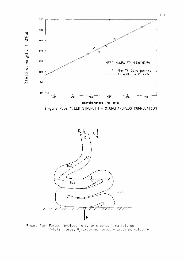
200
IBO -
160 -
140 -
120 -
100 -
80
1
-
-
- o 1
1 — • 1
G ) ^ ^
_ ^ ^ o
i i
I I I -~p,
O^""^
HE30 ANNEALED ALUMINIUM
o (Hm.Y) Data points
T= -oU.L) + U.oL)llm
i i i
400 650 450 500 550 600
MIcrohardneee, Hm (MPs)
Figure 7.5, YIELD STRENGTH - MICROHARDNESS CORRELATION
/7^77~77 77777V 777 77777
v=0
77~7WyV 7~77~
ure 7 . 6 : Forces i n v o l v e d i n dynamic c o n c e r t i n a f o l d i n g ; P = t o t a l f o r c e , P ^ c r u s h i n g f o r c e , v = c r u s h i n g v e l o c i t y
7.3.2 NUMERICAL MODEL
The a x i a l co l l apse of tubes was s imu la ted us ing the 2-D
numerical code descr ibed in chapter 4. Ax isymmetr ic cont inuum MTQC
elements (sec t . 4.2.3) were used under an e x p l i c i t t ime-march ing
procedure.
The tubes were crushed between two p l a t e n s ; the bottom one was
f i x e d , w h i l e the top p la ten moved downwards, causing the tube t o
c o l l a p s e . The p l a t e n s , as the res t of the t ube , were model led w i t h
axi symmetric continuum elements. In teract ion between platens and tube
as we l l as between tube f o l d s themselves was considered through
numerical contacts (sec t ion 4.8).
In order f o r the c a l c u l a t i o n s t o be mean ing fu l , i t must be
checked t h a t ax isymmetr ic de format ions are to be expected f o r the
p a r t i c u l a r tube geometry, e.g. by l o c a t i n g the app rop r i a te po in t in
the collapse c l ass i f i ca t i on chart ( f igure 7.2). Non-axisymmetric modes
of co l l apse such as the diamond mode cannot be s i m u l a t e d , as ax ia l
symmetry of deformat ion i s imposed by the model. The analyses
performed here a l l corresponded to experimental ly observed concertina
f a i l u r e s .
Apart from the axial symmetry, no fu r ther numerical constra ints
were imposed upon the model, being comple te ly f r ee to develop i t s
preferred form of collapse (e.g. simultaneous, sequential) as well as
the number and length of f o l d s . No geomet r ica l i m p e r f e c t i o n s were
introduced to t r igger of f buckling modes. 'Natural ' imperfect ions were
provided by the random numerical roundoff er rors .
The axial collapse of tubes is a f a i r l y re l i ab le and repeatable
mechanism (e.g. Ghani, 1982), i n d i c a t i n g l i t t l e s e n s i t i v i t y to
imperfect ions. In the numerical model, the imperfections depend on the
precision of the f l oa t i ng point a r i thmet ic . A check was done, running
the same tube collapse model (TUBE7, see table 7.4), on a CRAY-IS (64-
b i t f l oa t i ng point words) and on a VAX 11/785 (32-bi t f l o a t i n g point
words). Results obtained were substant ia l l y i den t i ca l . The deviat ion
from the energy balance condit ion was larger on the VAX (0.15% error
versus 0.005% e r r o r on the CRAY), but s t i l l w i t h i n very acceptable

l i m i t s .
7.3.2.1 DISCRETIZATION AND MATERIAL
Discret izat ions wi th varying fineness were used for the analyses.
The meshes employed may be grouped in to the fo l lowing categories:
" Coarse mesh, 3 q u a d r i l a t e r a l MTQC elements through the thickness,
approximate aspect ra t i o 2:1 ( largest dimension a x i a l l y ) ;
" Medium mesh, 3 quadr i la tera l MTQC elements through the thickness,
approximate aspect ra t i o 1:1;
- Fine mesh, 4 q u a d r i l a t e r a l MTQC elements through the thickness,
approximate aspect ra t i o 1:1.
The p la tens were d i s c r e t i z e d w i t h two CST elements each in a l l
cases. They were assumed i n f i n i t e l y r i g i d , i.e. no deformations were
allowed.
Symmetric contacts (sect . 4.8) were used f o r the i n t e r a c t i o n
between oppos i te wa l l s i n the tube f o l d s . Each i n t e r a c t i n g node i s
inc luded in two s imul taneous numerical c o n t a c t s : f i r s t l y as an
i n t r u d e r on the opposi te s i d e , and secondly as par t of a t a r g e t s ide
being penetrated by the node opposite. This ensures f u l l y symmetrical
behaviour in the in ter face algori thms.
For the contacts between tube and p la tens only the tube nodes
were considered as i n t r u d e r s ; the lack of i n t e r m e d i a t e nodes in the
p la tens would have prevented o the rw i se . However, t h i s i s not
undesirable, as the contact between deformable tube and r i g i d platen
is natura l ly asymmetric.
For the material model, an e l as t i c - p l as t i c iso t rop ic Von Mises
idea l iza t ion was used. E las t i c parameters were
Elast ic modulus, E 67000 MPa
Poisson's ra t i o v 0.3
Strain-Hardening was considered wi th the power law obtained in chapter

6 (eqn. 6.20):
Y •= 181.7 e u - i o y (MPa)
The above hardening law was derived for HE30 annealed Aluminium bars.
HE30 and HT30 materials are ident ica l aluminium a l loys , except for the
fact that HE30 comes in bars (extruded), whereas HT30 comes in tubes
(drawn). A f t e r being annealed both m a t e r i a l s can be assumed to have
the same mechanical behaviour.
In e f fec t , dif ferences due to cold-working may be banished in the
anneal ing process. According to C o t t r e l l (1975), "work-harden ing is
caused by t h e mutua l o b s t r u c t i o n of d i s l o c a t i o n s g l i d i n g on
in te rac t ing systems". The anneal ing t rea tmen t produces recovery and
rec rys ta l l i za t i on processes. The recovery allows dis locat ions to move
out of the s l i p planes, disentangl ing and t idy ing-up the cold-worked
s t ruc ture , while the rec rys ta l l i za t i on replaces the cold-worked grains
by a new set of more perfect grains, giv ing complete softening. As on
the other hand the differences due to cold-working were only minor, i t
is j u s t i f i e d to assume the cons t i t u t i ve laws derived for annealed HE30
va l id for HT30 tubes as we l l .
7.3.2.2 VELOCITY SCALING (see also section 4.1.1)
E x p l i c i t t ime-march ing procedures by t h e i r nature can only
perform dynamic analyses. Quasi-stat ic or slow loading problems could
be solved in real t i m e , but u s u a l l y t h i s becomes too expensive. For
reasons of numerical s t a b i l i t y the maximum t ime-step is l i m i t e d by the
Courant c r i t e r i o n , which is independent of the ve loc i ty of loading. In
q u a s i - s t a t i c analyses such as these the c a l c u l a t i o n s need to be
speeded up, which may be done by a r b i t r a r i l y increasing the ve loc i ty
of deformat ion in the numerical model; t h i s i s c a l l e d " v e l o c i t y
sca l ing" .
For these calculat ions the crushing ve loc i ty employed was 20 m/s,
r e p r e s e n t i n g an i n c r e a s e of 5 o r d e r s o f magn i tude f r om t h e
exper imenta l v e l o c i t y . I t w i l l be seen (sec t ion 7.3.4.2) t h a t the
overshoots and d i s t o r t i o n in t roduced by t h i s amount of v e l o c i t y

s c a l i n g were s m a l l . As t h e r e was no s t r a i n - r a t e h a r d e n i n g i n t h e
m a t e r i a l , t h e on l y a d d i t i o n a l s a f e g u a r d needed was t o ensure t h a t
dynamic e f f e c t s c o n t i n u e d t o p l a y a s m a l l r o l e i n t he mechan ica l
de format ion process. Some c r i t e r i a to quan t i f y t h i s r o l e were given in
s e c t i o n 6 . 5 . 1 .
The dynamic fo rces i nvo lved i n the conce r t i na c rump l i ng may be
assessed w i t h the f o l l o w i n g s imp le c o n s i d e r a t i o n s . F igure 7.6 shows a
wa l l sec t ion in a tube which i s being crumpled w i t h an ax ia l v e l o c i t y
v. The p o r t i o n o f t h e t u b e a l r e a d y c r u m p l e d (be low A) i s s t a t i o n a r y ,
the undeformed p o r t i o n above C moves w i t h v e l o c i t y v, and the f o l d i n g
p o r t i o n between A and C i s b e i n g d e c e l e r a t e d f r o m v t o 0. T h i s
d e c e l e r a t i o n occurs i n a t i m e ( h - 2 t 0 ) / v > h b e i n g t n e f o i d l e n g t h and
t o t h e w a l l t h i c k n e s s ; t h e average i n e r t i a f o r c e necessary i s , by
v i r t u e of Newton's second law,
P-i = 7 T D t 0 p h v 2 / ( h - 2 t 0 ) (7 .8 )
where D i s the mean tube Diameter and p i s the mass dens i t y . Hence the
average dynamic forces grow w i t h the square of the c rush ing v e l o c i t y ,
a l l o ther f ac to r s being constant f o r a p a r t i c u l a r t u b e .
The t o t a l fo rce F exer ted at the bottom sur face equals the fo rce
n e c e s s a r y f o r c r u m p l i n g f e l t a t D, PC j p l u s t h a t necessary f o r
d e c e l e r a t i n g the f o l d ABC, P i :
p = pc + P i = Pc + 7 T D t 0 p v 2 h / ( h - 2 t 0 ) ( 7 .9 )
The deformat ion v e l o c i t y v used in the c a l c u l a t i o n s was chosen so
as t o produce acceptably smal l dynamic d i s t o r t i o n s (Pi < 5%Pc'* T n e s e
dynamic e f f e c t s are q u a n t i f i e d in sec t ion 7.3.4.2, where the i n f l uence
of the v e l o c i t y s c a l i n g i s d iscussed.
7 .3 .2 .3 INTERPRETATION OF OUTPUT
L o a d - c o m p r e s s i o n c u r v e s o b t a i n e d f r o m n u m e r i c a l a n a l y s i s
needed some p o s t - p r o c e s s i n g ( a v e r a g i n g and f i l t e r i n g ) i n o r d e r t o
f a c i l i t a t e t h e i r i n t e r p r e t a t i o n .

186
F i r s t l y , a rep resen ta t i ve value of the load was taken as the
average between the loads measured at the top and bottom p la tens at
each instant . In a quas i -s ta t ic s i tua t ion the di f ference between both
measurements would be neg l ig ib le . Here, due to the ve loc i ty sca l ing,
there were f i n i t e , a l though s m a l l , d i f f e rences between the two end
loads.
Secondly, h igh- f requency o s c i l l a t i o n s in the load h i s t o r i e s
ar is ing from stress-wave propagation between the two extremes of the
specimen were f i l t e r e d out, using a centred moving average f i l t e r (see
below). Again in a t r u e q u a s i - s t a t i c model t h i s would not be
necessary; for each load increment, the new displacements are those
that f u l f i l l s ta t ic equ i l ib r ium. I t is assumed that the stress waves
have t r a v e l l e d back and f o r t h along the specimen many t i m e s ,
red i s t r i bu t i ng stresses, and eventually damped out.
The v e l o c i t y of de fo rmat ion has been g r e a t l y increased here,
while the information (stress waves) continues to be t ransmi t ted at
the same speed. On the other hand, there are steep changes in load due
to the buck l ing i n s t a b i l i t i e s and rap id v a r i a t i o n s in boundary
c o n d i t i o n s ( con tac t - impac t ) . Whereas in the real - slow loaded -
specimen there i s s t i l l t ime f o r numerous s t ress waves to t r a n s m i t
these changes smoothly enough, here they are t ransmi t ted more abruptly
as f i n i t e amplitude dynamic pulses, occasioning v i s i b l e osc i l l a t i ons
in the load curves. As long as the ampl i tude of these o s c i l l a t i o n s
remains small re la t i ve to the to ta l loads, t h e i r d i s t o r t i v e inf luence
is not important, and the underlying trend in the load curves may be
recovered by f i l t e r i n g them out.
High frequency f i l t e r (centred moving average)
Centred moving average techniques are s imple and e f f e c t i v e f o r
high frequency f i l t e r i n g . From a given t ime series x t -j=i to N, wi th
constant t ime in terval At, a new f i l t e r e d t ime series is defined as
i+M
Yi = 1 / xj M<i<N-M ( 7 . 1 0 ) 2M+1 i-M
This f i l t e r removes frequencies higher than l/(2MAt). The values

18
of M were chosen so as t o remove o s c i l l a t i o n s occasioned by s t r e s s -
wave propagation.
7.3.3 RESULTS FROM NUMERICAL CALCULATIONS AND EXPERIMENT
Numer i ca l r e s u l t s are p r e s e n t e d here and compared w i t h
experiment, fo r the axial col lapse of 4 d i f f e ren t tube geometries:
- Tube geometry A, ID=19.05mm, t0=1.64mm, L=50.8mm;
- Tube geometry 6, ID=19.05mm, t0=1.17mm, L=50.8mm;
- Tube geometry C, 0D=38.10mm, t0=1.65mm, L=50.8mm;
- Tube geometry D, 0D=25.40mm, to=0.95mm, L=25.4mm.
Other a u x i l i a r y c a l c u l a t i o n s were necessary f i r s t in order to
t e s t the i n f l uence of var ious parameters and cho ices :
- velocity of deformation;
- mesh refinement;
- friction;
- element type.
Resul ts from these a u x i l i a r y c a l c u l a t i o n s are discussed in sec t ion
7.3.4. In t o t a l over 20 c a l c u l a t i o n s of the complete tube c rump l i ng
process for 6 d i f fe ren t tube geometri-es (table 7.4) were car r ied out
successful ly.
Mesh ref inement was found to have an impor tan t e f f e c t upon the
r e s u l t s (sect ion 7.3.4.3). However, due to the high computer costs
involved in these analyses, some of the meshes used could not have the
maximum desirable fineness. Two of the models presented below have a
" f ine" mesh, while the other two have "medium" meshes.
The numerical p r e d i c t i o n s are presented toge the r w i t h the
corresponding exper imenta l r e s u l t s . The t e s t s were descr ibed i n
sec t i on 7 . 3 . 1 .
The computer used f o r the numerical work was a CRAY-IS of the
University of London. Central Processing Unit (CPU) times quoted refer

to th is machine.
7.3.3.1 TUBE GEOMETRY A: ID=19.05mm, to =1.64mm, L=50.8mm
A " f i n e " mesh was used f o r t h i s a n a l y s i s , compr i s ing 633 nodes
and 996 t r i a n g u l a r c e l l s ( f i g . 7.7.a). The c a l c u l a t i o n proceeded f o r
95789 t i m e - s t e p s , up to an a x i a l compression of 37.5mm, fo rm ing 3
concertina fo lds : f i r s t l y at the bottom end, then at the top, f i n a l l y
i n the middle ( f i g . 7.7b). CPU t ime f o r t h i s c a l c u l a t i o n was 8641
seconds.
In the experiment, the tube collapsed forming 3 concertina folds
as w e l l , w i t h a shape very s i m i l a r t o the numer ical p r e d i c t i o n
( f i gu res 7.8, 7.9). Figure 7.10 con ta ins the load-compress ion curves
(numerical and expe r imen ta l ) , which show a remarkable agreement.
Average co l lapse loads were 12.2 kN f o r the c a l c u l a t i o n s and 11.9 kN
f o r the exper iment . The succession of peaks and v a l l e y s i n the load
curves is due t o the a l te rnancy between a x i a l compression ( s t i f f e r
peaks) and bending (less s t i f f val leys) mechanisms. The snapshot views
of the mesh at d i f f e ren t points included in f igure 7.10 conf irm th is
exp lana t i on , p rov i d i ng a d e t a i l e d d e s c r i p t i o n of a phenomenon
p rev ious ly observed expe r imen ta l l y in a f o r ce fu l l y more qua l i t a t i ve
manner (Ghani, 1982).
The numerical load-compression curve in f igure 7.10 was obtained
by averaging and f i l t e r i n g the raw data as exp la ined in sec t i on
7.3.2.3. To show the e f f e c t of t h i s a v e r a g i n g - f i l t e r i n g process,
indiv idual load curves obtained d i rec t l y at the top and bottom platens
are presented in f igure 7.11. These curves show some small t rans ient
imbalances due to the ve loc i t y s c a l i n g . The unde r l y i ng q u a s i - s t a t i c
t rend is seen more c l e a r l y when t h i s noise is f i l t e r e d out ( f i g .
7.10).
The various energy components were monitored (sect. 4.10) during
the c a l c u l a t i o n s ( f i g . 7.12). the energy of de fo rmat ion in f i g . 7.12
comprises p l a s t i c work, recoverable e l a s t i c energy, and energy
dissipated through f r i c t i o n (some 1.4% of the p las t i c work at the end
of the analysis). In order to provide a check for the s t a b i l i t y of the

189
6 6
CO
ID--19. 05mm
HT30 ANNEALED ALUMINIUM
TUBE
:-l
tosl.64mm
Rigid Platens
b) mesh a f t e r 37.5mm a x i a l c o m p r e s s i o n
gure 7 . 7 : C a l c u l a t i o n s f o r a x i a l c o l l a p s e o f t u b e ID= l9 .05mm, t = l .64mm, L=50.8mm ( t u b e g e o m e t r y A)

AXIAL COLLAPSE ID=19.05mm, t 0=1.64mm, L=50.8mm TUBE
-• — . • ^ * * 1 ^ v * *
Figure 7.8: View of crumpled tube (geometry A)
AXIAL COLLAPSE ID=19.05mm, t 0=i.64mm, L=50.8mm TUBE
,i n.
J ...L , J i. J .1
Figure 7.9: Section of crumpled tube (geometry A)

JSZ
CD O
20.00
18.00
16.00
AXIAL COLLAPSE OF TUBE ID=l9.05mm, t =l.64mm, L=50.8mm
o
(Gecmetry A)
EXPERIMEN CALCULATI
o.oo o.oo 5.00 10.00 15.00 20.00
S t r o k e (mm)
FIGURE 7.10: CALCULATIONS FOR AXIAL COLLAPSE OF TUBE; LOAD - COMPRESSION CURVE

20.00
CD
o
Bot tom p l a t e n Top p Laten
A x i a l c o l l a p s e 0 5 m m , t „ = 1 . 6 '4mm, L = 5 0 . 8 m m T u b e
15 20
S t r o k e (mm)
F i g u r e 7 . 1 1 . INDIVIDUAL LOAD CURVES FOR NUMERICAL MODEL AT BOTH PLATENS
500
450
400
350
D O
~> "
>^ cn 0) c
LU
300
250
200
150
100
50
Tube geometry A A x i a l co I l a p s e
I D = 1 9 . 0 5 m m , t0=1 . 64mm, L = 50 .8mm Tube
E x t e r n a l w o r k
T o t a l d e f o r m a t i o n e n e r g y
P l a s t i c w o r k
K i n e t i c e n e r g y
0.00 0.20 0.40 0.60 0.80 1.00 1.20 1.40 1.60 1.80
T ime (msec)
Figure 7.12s ENERGY HISTORIES FOR NUMERICAL MODEL

computa t ions , the work done by the ex te rna l fo rces was computed
independently and compared to the sum of the deformation and k ine t ic
energies. Within the precision of the f igures (5 d i g i t s ) no di f ference
was perceived between both values, ind icat ing absence of i n s t a b i l i t i e s
and soundness of numerical in tegrat ion algori thms.
Contour maps of the Von Mises f low stress (Y), from the numerical
model and experiments, are presented in f igure 7.13. The experimental
data were der ived from microhardness t e s t s , as l a i d out in sec t ion
7.3.1.3. S i m i l a r pa t te rns and l e v e l s of s t ress can be observed f o r
both cases, although somewhat steeper gradients and a wider range of
values is appreciable for the experiment. This is due on the one hand
to the higher curvature for the experimental f o l d selected, and on the
other hand to the re la t i ve coarseness of the numerical mesh. Agreement
f o r a l l these loca l e f f e c t s would need an i n o r d i n a t e degree of mesh
re f inement . Consider ing the u n c e r t a i n t i e s of the microhardness
measurements and of t h e i r c o r r e l a t i o n to the m a t e r i a l s t r e n g t h , Y,
th is level of agreement was deemed very good.
7.3.3.2 TUBE GEOMETRY B: ID=19.05mm, t0=1.17mm, L=50.8mm
This problem was d i s c r e t i z e d w i t h a mesh of medium f i n e n e s s ,
compr is ing 532 nodes and 784 t r i a n g u l a r c e l l s ( f i g u r e 7.14a). 99503
computational t ime-steps were needed for an axial compression of 40
mm. 3 f u l l concertina folds plus a four th incomplete fo ld were formed
( f i g u r e 7.14b). The order of f o rma t i on was: bot tom, t o p , second from
bottom, second from top. CPU time consumed was 7176 seconds.
In the corresponding experiment 4 f u l l fo lds were formed in the
tube ( f i gu res 7.15, 7.16). The discrepancy between exper iment and
c a l c u l a t i o n in the f o u r t h f o l d arose from an o v e r p r e d i c t i on of the
f o l d leng th in the numerical model. The f i r s t 3 f o l d s spanned an
excessive tube length, not leaving enough for the natural formation of
a f o u r t h f o l d . The reason f o r t h i s o v e r p r e d i c t i o n i s an excess
s t i f fness of the model, caused by the coarseness of the d i sc re t i za t ion
employed. Convergence towards the experimental behaviour was observed
from a previous ana lys i s of t h i s same problem w i t h a coarse mesh
(sec t ion 7.3.4.3). No f u r t h e r re f inements of the mesh were performed

194
'X* y - 4 "X
'/r >v . / • <» »
•J:
-\ • •. v
• '•.; • . . < o
z:r " ^ : « i
\
r\ r-.rs
*X
^
.V
t
xlOMPa
a) from numerical c a l c u l a t i o n s
b) from microhardness t e s t s MPa
Figure 7.13: Contours of y i e l d s t r e n g t h Y i n crumpled tube s e c t i o n (10=19.05mm, t =I.64mm, L=50.8mm Tube) (geometry A)

195
Rigid Platens
b) Mesh after 40mm axial compression
(•iqure 7.14: Calculations for axial collapse of tube ID=19.05mm, to=l.l7mm, L=50.8mm, tube geometry B
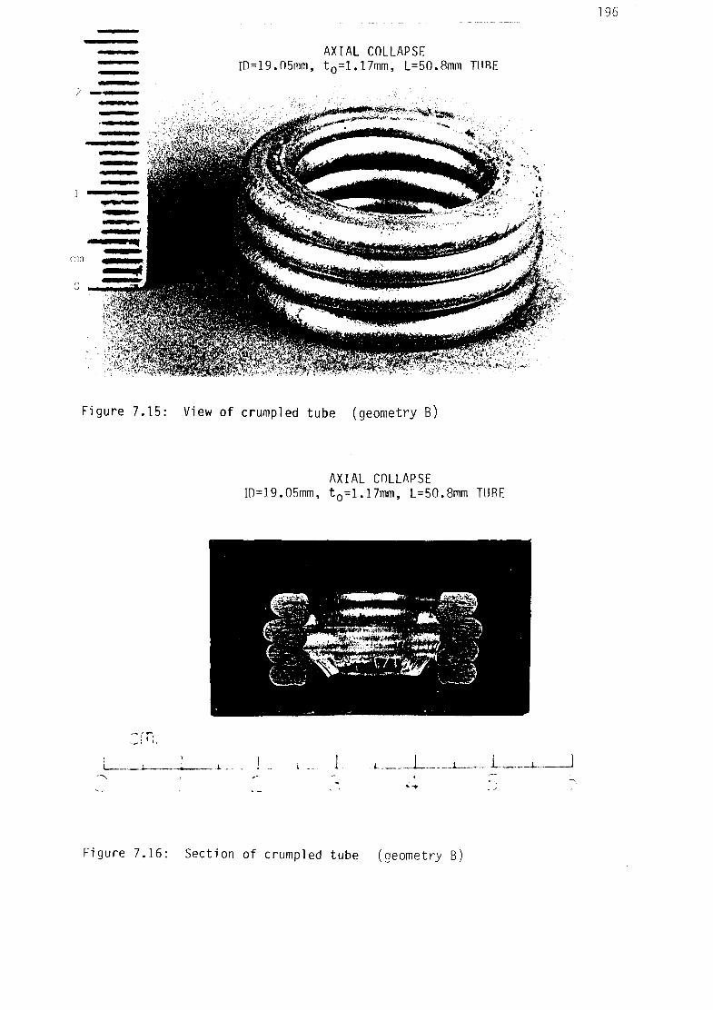
AXIAL COLLAPSE ID=19.05mm, t0=l.17mm, L=50.8mm HIRE
Figure 7.15: View of crumpled tube (geometry B)
AXIAL COLLAPSE m=19.05mm, t0=1.17mm, L=50.8mm TUBE
._; i ; .
i ... 1... -L. 1.
Figure 7.16: Section of crumpled tube (geometry B)

in order to avoid excessive computer costs.
Fur ther i n s i g h t i n t o the behaviour of the model may be gained
from the load-compression curves ( f i g u r e 7.17). S i m i l a r load l e v e l s
and pa t te rns of r i ses and f a l l s in the curves were obta ined in
experiment and ca lcu la t ion . However, the separation between successive
peaks is greater for the numerical model, ind ica t ing longer fo lds . For
the last f o l d the length of tube remaining is too short. A very s t i f f
f i na l fo ld is then formed, wi th a large degree of shear deformation.
Computed load levels become here much greater than experimental ones.
Nei ther the i n d i v i d u a l u n f i l t e r e d load-compress ion curves f o r
both p la tens nor the energy balance graph, given f o r the prev ious
ana lys i s (tube geometry A)in f i g s . 7.11 and 7.12, are given f o r t h i s
or the fo l lowing tube analyses (geometries B, C, D). The story t o l d by
these graphs is much the same as for tube geometry A.
Numerical and experimental contour maps of Von Mises st rength, Y,
are given in f i g u r e 7.18. As f o r tube geometry A, s i m i l a r l e v e l s and
pa t te rns of s t ress may be apprec ia ted in both maps. Again , the
gradients for the experimental contours are steeper.
7.3.3.3 TUBE GEOMETRY C: 0D=38.1mm, t0=1.65mm, L=50.8mm
A " f i ne " mesh was used f o r t h i s a n a l y s i s , w i t h 633 nodes and 996
t r iangu lar ce l l s . The i n i t i a l and f i na l conf igurat ions of the mesh may
be seen in f i g u r e 7.19. One concer t i na f o l d was formed at e i t h e r end
of the tube. As for the previous analysis, the length of the folds was
ove rp red i c ted , l eav ing too l i t t l e tube leng th l e f t f o r the proper
formation of a t h i r d f o l d in the middle. Although at one point i t did
seem t h a t a t h i r d shor te r f o l d would be fo rmed, e v e n t u a l l y t h i s
mechanism proved too s t i f f and the model f a i l e d through shear near the
top.
The experimental resul ts did not show th i s behaviour, producing 3
complete f o l d s ( f i gu res 7.20 and 7.21). The load-compress ion curves
( f igure 7.22) show tha t , although somewhat t ranslated to the r ight for
the ca lcu la t ions, a great s i m i l a r i t y exists between the experimental

\ r, I BS^
X> / \ J *~ ?•
v
V
AXIAL COLLAPSE OF TUBE
ID=l9.05mm, t = I . I 7mm, L=50.8mm o
(Geometry B)
0.00 5.00 10.00 15.00 20.00 25.00
-St roke (mm)
FIGURE 7.17: CALCULATIONS FOR AXIAL COLLAPSE OF TUBE; LOAD - COMPRESS

199
xlOMPa
a) from numerical c a l c u l a t i o n s
b) from microhardness t e s t s
Figure 7.18: Contours of y i e l d s t r e n g t h in crumpled tube sec t i on (ID=19.05mm, t Q = i . |7mm, L=50.8mm Tube) (geometry B)

200
OD = 38.lmm
b E
00
O
\i=
V= 20m/s
:::a to-l65mm
ES3
HT 30 ANNEALED ALUMINIUM TUBE
Fine Mesh solution
a) Undeformed mesh
^Rigid Platens
I b) Mesh after 38mm axial compression
Fi gure 7.19: Calculations for axiaI col lapse of tube 0D=38.lmm, t =l.65mm, L=50.8mm , tube geometry C

AXIAL COLLAPSE 00=38.lmm, t0=1.65mm, L=50.8mm TUBE
/.. . - *n
w cm.
201
O 3 4 5 6
Figure 7.20: View of crumpled tube (geometry C)
AXIAL COLLAPSE 00=38.lmm, t0=1.65mm, L=50.8mm TUBE
Figure 7.21: Section of crumpled tube (geometry C)

EXPERIMENT CALCULATION
.AXIAL COLLAPSE OF TUBE - 00=38.111111, t0=l,65na L^O.Snm
0.00 5.00 10.00 15.00 20.00 25.00
-Stroke (mm)
F igu re 7 .22 : CALCULATIONS FOR AXIAL COLLAPSE OF TLBE - LOAD VS COMPRE

and numerical load pa t te rns f o r the f i r s t f o l d . The de fo rmat ion
process can be c lear ly understood by examining the snapshot views of
the mesh inc luded in f i g u r e 7.22. At po in t A in the f i g u r e , a f t e r the
b ending and s l i d i ng of the top edge, contact has been made between the
outer wa l l of the tube and the top p l a t e n , occas ion ing a sharp
increase in load. The edge then separates s l i g h t l y from the top platen
leaving only the outer f o l d surface in contact wi th the platen. With
fur ther compression the fo ld continues to bend u n t i l the bottom part
of the f o l d h i t s the top edge. This produces a r i p p l e c l e a r l y
no t i ceab le i n both exper imenta l and numerical load curves (B). The
bottom part of the f o ld then pushes the edge up u n t i l contact wi th the
top p la ten i s renewed. The load increases s teep ly f o r a moment when
the tube deforms in ax ia l compress ion, u n t i l the bottom edge s t a r t s
s l i p p i n g (C) and bending t o form another f o l d (D). The l a s t f o l d i s
ready to be formed at E, but the remaining tube length has become too
shor t . A yery high load i s necessary, which even tua l l y l e v e l s o f f as
shear f a i l u re occurs.
The numerical and exper imenta l maps of Von Mises s t reng th (Y),
given in f i g u r e 7.23, i n d i c a t e again s i m i l a r s t ress d i s t r i b u t i o n s
around a f o l d . They a lso show the same pa t t e rn as the two prev ious
analyses.
7.3.3.4 TUBE GEOMETRY D: 0D=25.4mm, to =0.95mm, L=25.4mm
The mesh employed for th i s problem was of medium fineness, w i th
332 nodes and 484 t r i a n g u l a r c e l l s ( f i g u r e 7.24a). A drawing of the
deformed mesh a f te r an axial compression of 20.2 mm is given in f igure
7.24b, showing 2 concer t i na f o l d s . 53554 computa t iona l cyc les were
performed, using 2664 CPU seconds.
the experimental resu l t s , shown in f igures 7.25 and 7.26, proved
again to be s l i g h t l y less s t i f f than the computational model. In the
exper iment , a f t e r the f i r s t 2 f o l d s , some ex t ra leng th remained t o
form another h a l f f o l d . Load compression curves f o r exper iment and
c a l c u l a t i o n s are given in f i g u r e 7.27. In a way the comparat ive
behaviour here i s the inverse of t h a t repor ted f o r the previous two
analyses. Here i t is in the experiment where a shorter length of tube

204
xlOMPa
a) from numerical c a l c u l a t i o n s
b) from microhardness t e s t s
Figure 7.23: Contours of y i e l d s t r eng th Y in crumpled tube sec t i on
(0D=38.lmm, t =I.64mm, L=50.8mm Tube)(geometry C)

205
OD= 25.4 mr
1 A.
e E
HT30 ANNEALED ALUMINIUM TUBE
Medium Mesh solution
to=0.95mm.
a) Undeformed mesh
Rigid Platens
b) Mesh a f t e r 20.2mm a x i a l c o m p r e s s i o n
F i g u r e 7 . 2 4 : C a l c u l a t i o n s f o r a x i a l c o l l a p s e o f t u b e 0D=25.4mm, t =0.95mm, L=50.8mm, tube geometry D
o

AXIAL COLLAPSE 00=25.4mm, to=0.95mm, L=25.4mm TUBE
Figure 7.25: View of crumpled tube (geoinetry D)
AXIAL COLLAPSE 00=25.4mm, to=0.95mm, L=25.4mm HIRE
.1 I !.
_J 1_ ..: _± 4 3
Figure 7.26: Section of crumpled tube (geometry D)
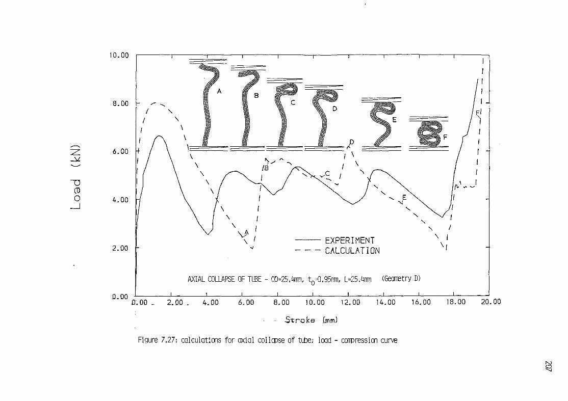
10.00
8.00
6.00
4.00
2.00 -
0.00
EXPERIMENT CALCULATION
AXIAL COLLAPSE OF TUBE - 0D=25.%ni t0=0.95rmb L=25.4mii
0.00 _ 2.00 _. 4.00 6.00 8.00 10.00 12.00 1
S t r o k e (mm)
Figure 7.27: calculations for axial collapse of tube; load - conpression

remains at the end, occasioning s t i f f e r behaviour. The s t i f f en ing is
not so t rag ic though, because the extra length occurs at one end; t h i s
end eventually sl ipped towards the outside rounding of f i t s inner edge
through f r i c t i o n w i t h the p l a t e n . The numerical model does not have
enough de f i n i t i on to represent these edge e f fec ts . I t se t t les for two
s l i g h t l y longer fo lds than what would be preferred.
the e v o l u t i o n of the load curves ( f i g . 7.27) f o r the f i r s t f o l d
show again the same s i m i l a r i t i e s between experiment and calculat ions
as f o r tube geometry C (sect . 7.3.3.3), and they may be exp la ined in
i d e n t i c a l fash ion (po in ts A,B,C,D,E,F in f i g . 7.27).
7.3 .4 PARAMETRIC STUDIES IN NUMERICAL ANALYSES
The i n f l uence of the f o l l o w i n g parameters and
modelling choices upon ca lcu la t ion resul ts is s tud ied:
- Coeff ic ient of f r i c t i o n for tube-tube and tube-platen contacts;
- Velocity sca l ing;
- Mesh refinement;
- Element type.
The aim i s to ob ta in numerical feedback, in order to se lec t the
c h a r a c t e r i s t i c s of the models t o be employed i n the numer ical
analysis.
Some of the analyses presented here correspond to tube geometries
already mentioned in section 7.3.3 (A,8,C,D); there the f i na l analyses
were presented. Here the resul ts of pre l iminary analyses (table 7.4)
are considered.
7.3.4.1 INFLUENCE OF FRICTION
A Coulomb law of f r i c t i o n was used in the numerical model
(sec t ion 4.8.1). The t a n g e n t i a l f o rce Ft a t t n e i n t e r f a c e i s l i m i t e d
by the normal fo rce between the sur faces in c o n t a c t , Fn> anc( t n e
coefficient of f r i c t i on , fi:

F t 4 ^ F n (7 .11)
An experimental determination of the f rac t iona l behaviour of the
surfaces and m a t e r i a l s i nvo lved was not a t tempted w i t h i n t h i s
i n v e s t i g a t i o n . In a s t r i c t sense, the pe r fec t f r i c t i o n given by the
Coulomb law is not appl icable for a l l types of surfaces and arb i t ra ry
acting normal pressures (Curnier, 1984). This idea l i za t ion represents
an approximation to the f r i c t i o n phenomenon, consistent wi th our lack
of knowledge and experimental data about i t .
The inf luence of the var ia t ion of the coe f f i c i en t of f r i c t i o n was
studied by performing several tube collapse analyses on the same model
(Tube geometry E, f i g . 7.28). Values f o r \i ranged between 0.0
( f r i c t i on less ) and 0.3. The resul ts are summarized in f igures 7.29 and
7.30. For comparison, the corresponding experimental resul ts are also
included in f igure 7.29; the collapse geometry obtained experimental ly
consisted of 3 1/2 concertina fo lds.
The collapse of the f r i c t i o n l e s s model was considerably d i f f e ren t
from the other models and from the exper imenta l r e s u l t s , producing
only two large concertina fo lds . The other models a l l produced three
folds and load-compression curves s im i l a r to each other. The resul ts
f o r ju. = 0.2 and [i= 0.3 were p a r t i c u l a r l y c l ose . A tendency f o r
shor te r f o l d lengths i s observed as f r i c t i o n decreases. This can be
a t t r i b u t e d t o edge e f f e c t s , cons ide r i ng t h a t f o r t h i s p a r t i c u l a r
problem two out of the th ree f o l d s occur at the tube ends, where the
constraint is smaller the less f r i c t i o n between tube and platen.
The reason for the di f ference between experimental and numerical
r e s u l t s i s t h a t the numerical model was i n s u f f i c i e n t l y r e f i ned in
terms of the "coarse" mesh used and v e l o c i t y s c a l i n g (40m/s p la ten
v e l o c i t y ) . As w i l l be seen in f u r t h e r s e c t i o n s , more r e f i n e d models
are necessary f o r good p r e d i c t i o n s . However, f o r the paramet r i c
s tud ies a la rge number of computer analyses was necessary, and cost
considerations forced compromises in the model refinement.

210
± O D ^ 38.1 m m ±
E E
CO
O ;; HT30 ANNEALED |ALUMINIUM TUBE
to = l. 22 mm
Figure 7.28: Tube model used for friction and velocity scaling parametric analyses

0.00 5.00 0.00 15.00 20.00 25.00 3
S t r o k e (mm)
Figure 7.29, INFLUENCE OF FRICTION ON N

212
a) u=0.0 (TUBED
b) p=0.1 (TUBE2)
c) M=0.2 (TUBE3)
d) u=0.3 (TUBE4)
TUBE GEOMETRY E
Figure 7.30, FINAL DEFORMED MESHES FOR DIFFERENT VALUES OF FRICTION (u)
0D=38.Imm, t,= 1.22mm, L=50.8mm TUBE COLLAPSE ANALYSIS
213
7.3.4.2 INFLUENCE OF VELOCITY SCALING
The c a l c u l a t i o n s presented in sec t ion 7.3.3 a l l had an ax ia l
v e l o c i t y of de fo rmat ion of 20 m/s, rep resen t ing a s c a l i n g up of the
experimental ve loc i t ies of f i ve orders of magnitude. Some results are
presented here studying the inf luence of varying the crushing ve loc i ty
in the model, j u s t i f y i n g the choice made f o r the f i n a l analyses in
section 7.3.3.
Three analyses were performed wi th ve loc i t i es of 10, 20, and 40
m/s on the same model as sec t . 7.3.4.1 (tube geometry E, f i g . 7.28).
The value of the f r i c t i o n c o e f f i c i e n t was se lec ted as [i= 0. 2. The
resul ts are summarized in f igures 7.31 and 7.32. A ramp was introduced
in the applied veloc i ty h istory for the beginning of the deformation,
the v e l o c i t y i nc reas ing from 0 t o i t s f i n a l value i n 0.1 msec. This
was found to produce a smoother s t a r t f o r the de format ion and fewer
i n i t i a l o s c i l l a t i o n s .
A l l th ree analyses produced 3 conce r t i na f o l d s in the tube. The
t h i r d central f o ld was s l i g h t l y shorter fo r 20 m/s and 10 m/s than for
40 m/s. In the load-compression curves ( f i g . 7.31), some di f ference is
noticeable when the ve loc i ty is decreased from 40 m/s to 20 m/s, but
f u r t h e r reduc t ion t o 10 m/s produced very l i t t l e d i f f e r e n c e . The
average co l l apse loads show a monotonic decrease towards the
experimental value, again the resul ts fo r 20 m/s and 10 m/s being very
close.
The c r i t e r i o n proposed in sec t ion 7.3.2.2 f o r eva lua t i ng the
dynamic forces involved in the wall crumpling, Pi > maY De u s e d here. From equation (7.8), the fo l lowing resul ts were obtained:
v=40 m/s Pi=0.737 kN (8.2% of Pc*P t )
v=20m/s Pi=0.184 kN (2.0% of Pc* p t )
v=10m/s Pi=0.046 kN (0.5% of Pc* p t )
Judging from these resu l ts , a ve loc i ty of 20 m/s was selected for
the f i n a l analyses. The i n e r t i a fo rces in t roduced by t h i s v e l o c i t y
scaling were smal l . Only marginal improvements are produced when the
veloc i ty is fu r ther reduced, whi le computational costs grow rapidly

22.00
_V
CD O
0.00 0.00 5.00
p-j^ure 7.31
10.00 15.00 20.00 25.00 30.00
Stroke (mm)
INFLUENCE OF DEFORMATION VELOCITY ON

215
a) v=40m/s. MTQC ELEMENTS (TUBES)
b) v=20m/s. MTOC ELEMENTS (TUBE?)
c) v=10m/s, MTQC ELEMENTS (TUBE8)
d) v=40m/s. MTQ ELEMENTS (TUBE6)
(TUBE GEOMETRY E)
Figure 7.52, FINAL DEFORMED MESHES FOR VARIOUS CRUSHING VELOCITIES AND
ELEMENT TYPES - 0D=38.1mm. t.= 1.22mm. L=50.8mm TUBE COLLAPSE

216
(1758 CPU sees, for 20m/s, 3474 CPU seconds for 10 m/s).
7.3.4.3 INFLUENCE OF MESH REFINEMENT
The i n f l u e n c e of mesh re f inement in th ree d i f f e r e n t cases was
studied (tube geometries A, B, and C). These models have already been
discussed in section 7.3.3, where resul ts for the more ref ined meshes
considered here were given.
For tube geometry B ( f i g . 7.14a, sec t . 7.3.3.2), two analyses
w i t h "coarse" and "medium" meshes were done; some r e s u l t s are
p r e s e n t e d i n f i g u r e s 7.33 and 7.34. As can be seen , t h e mesh
refinement had a dramatic inf luence, increasing the number of folds
from 3 (coarse mesh) to 4 (medium mesh), more in l i n e w i t h the
exper imenta l r e s u l t s . The load-compression curve shows c l e a r l y the
shor te r length of f o l d s f o r the more r e f i n e d model. S t i l l the f o l d
length was s l i g h t l y overpredicted for the medium mesh, the 4th f o l d
being a very shor t and s t i f f one which e v e n t u a l l y f a i l s by shear.
Further refinement of the mesh would probably achieve better resu l ts .
For tube geometry A (sec t . 7.3.3.1, f i g . 7.7a) th ree d i f f e r e n t
mesh grades were used: "coarse" , "medium" and " f i n e " . The r e s u l t s ,
presented in f i g u r e s 7.35 and 7.36, are very i l l u s t r a t i v e ; mesh
ref inement produces a c l e a r and cons i s t en t convergence towards the
less s t i f f experimental values. The fo ld lengths are indicated by the
p o s i t i o n of the v a l l e y s in the load-compress ion cu rve ; these are
c o n s i s t e n t l y s h i f t e d towards the l e f t as the mesh is r e f i n e d ,
i nc reas ing the a v a i l a b l e leng th f o r the l a s t f o l d . As t h i s l a s t f o l d
grows nearer to i t s "natural" unconstrained length, the energy - and
thereby the force - involved in i t s formation decreases. A monotonical
approximation of the load levels produced in the las t fo ld towards the
experimental values is apparent as the mesh is re f ined.
L a s t l y , f o r tube geometry C (sec t . 7.3.3.3, f i g . 7.19a), "coarse"
and " f ine" mesh analyses were performed. The resul ts ( f i gs . 7.37,7.38)
fo l low a s im i la r pattern to those out l ined for the previous two cases:
a decrease in the ove rp red ic ted s t i f f n e s s and f o l d leng th w i t h mesh
refinement. As for tube geometry B ( f i gs . 7.33, 7.34), the coarse mesh

14.00
12.00 -
10.00 -
8.00 -
6.00
4.00
2.00 -
- EXPERIMENT Coarse Mesh Medium Mesh
(see table 7.4)
0.00
ID=19.05
0.00 5.00 10.00 15.00 20.00
S t r o k e (mm)
Figure 7.33, INFLUENCE OF MESH REFINEMENT

218
a) COARSE MESH, MTQC ELEMENTS (TUBE10)
b) MEDIUM MESH, MTQC ELEMENTS (TUBE12)
I
c) COARSE MESH, MTQ ELEMENTS (TUBE11)
Figure 7.34, FINAL DEFORMED VIEWS FOR VARIOUS MESHES AND ELEMENT TYPES ID=i9.05mm, t,=l.i7mm, L=50.8mm TUBE (geometry B)

16.00 -
14.00 -
10.00 -
0.00 5.00 10.00 15.00 20.00
S t r o k e (mm)
Figure 7.35* INFLUENCE OF MESH REFINEMEN

a) COARSE MESH. MTOC ELEMENTS (TUBE17) b) MEDIUM MESH. MTQC ELEMENTS (TUBE13)
c) FINE MESH. MTQC ELEMENTS (TUBE15) d) MEDIUM MESH, MTQ ELEMENTS (TUBE18)
e) MEDIUM MESH. CST ELEMENTS (TUBE16)
Figure 7.36, FINAL DEFORMED VIEWS FOR VARIOUS MESHES AND ELEMENT TYPES D=19.05mm, t,=1.64mm, L=50.8mm TUBE(geometry A)

CD O
24.00
22.00
20.00 \-
4.00
2.00 F
0.00
EXPERIMENT — Coarse Mesh (TUBE19)) • - Fine Mesh (TUBE21) j
0D=38.1mm
0.00 5.00 10.00 15.00 20.00 25
S t r o k e (mm)
Figure 7.37, INFLUENCE OF MESH REFINEMENT

222
a) COARSE MESH (TUBE19)
b) FINE MESH (TUBE21)
Figure 7.38: FINAL DEFORMED VIEWS FOR VARIOUS DEGREES OF
MESH REFINEMENT - 0D=38. 1mm, t.= 1.65mm. L=50.8<r
(tube geometry C)

model missed one fo ld al together. With the f ine mesh some more length
was a v a i l a b l e f o r the t h i r d f o l d , and i t s f o rma t i on was a t tempted .
However the model was s t i l l somewhat o v e r s t i f f ; the leng th of tube
l e f t over f o r the t h i r d f o l d was too s h o r t , and a shear f a i l u r e
mechanism was preferred f i n a l l y .
7.3.4.4 INFLUENCE OF ELEMENT TYPE
A l l the analyses repor ted above used the Mixed T r i a n g l e -
Q u a d r i l a t e r a l w i t h Cor rec t ion (MTQC) e lements , proposed i n sec t i on
4.2.3. Here an a t tempt i s made to assess the behaviour of these new
elements when compared to the previous Mixed T r i a n g l e - Q u a d r i l a t e r a l
(MTQ) elements (sec t ion 4.2.2) and Constant S t r a i n T r iang les (CST)
(sect. 4 .2 .1 ) .
I t was mentioned in sec t ion 3.7.1 t h a t CST meshes impose an
excessive number of vo lume t r i c c o n s t r a i n t s and t h e r e f o r e become in
p r a c t i c e a r t i f i c i a l l y s t i f f f o r incompress ib le p l a s t i c f l o w . Mesh
re f inement does not solve the problem, f a i l i n g to converge towards
true solut ions. MTQ elements solve th i s problem by reducing the number
of volumetric const ra in ts , but f o r ^ery l a rge deformat ions t a n g l i n g
over of the mesh can occur, creat ing unacceptable negative volumes. A
correct ion to prevent t h i s tangl ing over was proposed in section 4.2.3
wi th the MTQC elements.
The convergence of MTQC meshes has been proved i n the prev ious
sec t ion 7.3.4.3, where success ive ly f i n e r meshes were shown to
approach monoton ica l l y the exper imenta l r e s u l t s . Never the less , i t
seems inev i tab le that some s t i f f en ing be introduced by MTQC elements.
The aim here is to check, for pract ica l large deformation p las t ic f low
problems, that th i s s t i f f en i ng is smal l . I f so, i t w i l l be proved that
MTQC elements reta in the advantages of MTQ elements while at the same
time providing a more robust model.
I t must be mentioned t ha t a l l the low v e l o c i t y tube co l l apse
problems considered could be analyzed success fu l l y w i t h MTQ meshes.
Although in other cases negative volumes did occur (section 7.4.4), no
problems arose here due to the lack of boundary c o n s t r a i n t s and the

low deformation ve loc i t i es .
The "coarse" mesh tube model (tube geometry E, f i g . 7.28a) was
analyzed wi th MTQ and MTQC elements. Load-compression curves for both
c a l c u l a t i o n s are shown toge ther w i t h the exper imenta l r e s u l t s in
f i g u r e 7.39, where l i t t l e d i f f e r e n c e can be apprec ia ted between the
two ca lcu la t ions. The lower value of the minimum loads at the val leys
for the MTQ mesh denotes a lower resistance to high curvature bending
at f o l d s . This i s co r robora ted by i nspec t i on of the deformed shapes
( f igure 7.32a, 7.32d)
The same comparison as above was done f o r tube geometry B ( f i g .
7.14a). Results f o r coarse meshes w i t h MTQ and MTQC elements are
presented in f i g u r e s 7.40, 7.34a and 7.34c. I t was seen in the
previous sec t ion 7.3.4.3 t ha t the MTQC coarse mesh f a i l e d t o develop
the f o u r t h f o l d which was observed in exper iment . A s l i g h t l y b e t t e r
behaviour in th i s respect was obtained from the MTQ coarse mesh. For
the f i r s t three folds the length is very s l i g h t l y shorter than for the
MTQC mesh. Some extra length is l e f t over a f te r the f i r s t three fo lds ,
but s t i l l too short fo r the four th f o l d , evantual ly f a i l i n g in a high
curva tu re h inge. The improvement however i s f a r f rom t h a t obta ined
w i t h a f i n e r mesh ( f i g . 7.12b) where a f o u r t h f o l d was formed. Again
softer bending behaviour is appreciated for MTQ.
F i n a l l y the e f f e c t of d i f f e r e n t element types was s tud ied f o r
tube geometry A ( f i g . 7.7a). Ca l cu la t i ons were c a r r i e d out w i t h CST,
MTQ, and MTQC medium meshes, the resul ts being shown in f igures 7.41,
7.36b, 7.36d, and 7.36e. The great o v e r s t i f f n e s s of the CST mesh i s
i mmmediately apparent. The model is completely unable to represent the
concertina mechanism and buckles in to one large fo ld ( f i g . 7.36e) wi th
substant ia l ly higher loads ( f i g . 7.41). For the Mixed d iscre t iza t ions
MTQ and MTQC, no advantage i s apparent f o r MTQ as to f o l d lengths in
th is case." An excessively soft behaviour in high curvature bending is
exhibi ted by MTQ elements.
One p r a c t i c a l disadvantage of MTQ over MTQC elements is t h a t ,
even without developing negative volumes, some t r iangu la r ce l l s may
become very small i n s i z e . As i t i s c e l l s ize which governs the
computat ional t i m e - s t e p , t h i s means increased cost of a n a l y s i s . In

22.00
2.00
0.00 0.00
0D=38.1mm, t
5.00 10.00 15.00 20.00 25.00
S t r o k e (mm)
f i g u r e 7.39.- INFLUENCE OF ELEMENT TYPE ON

EXPERIMENT • - MTQC elements (TUB
MTQ elements (TUBE
\
\ W
\ Vi \ \ \
XT \/ \ ' v-
M c \
W 1 V I
\ '/
\ \ I / /\
ID=19.05m
0-00 5.00 10.00 15.00 20.00 2
S t r o k e (mm)
.Figure 7.40: INFLUENCE OF ELEMENT TYPE ON

CD O
28.00
26.00
24.00
22.00
20.00
18.00
16.00
14.00
12.00
10.00
8.00
6.00
4.00
2.00
0.00
< V
ID=19.05mm,
0.00 5.00 10.00 15.00 20.00
S t r o k e (mm)
Picure 7.41« INFLUENCE OF ELEMENT TYPE O
228
general i t was found that re f in ing MTQC meshes was a more consistent ,
robust and cheaper method of improving the resul ts than using sof ter
MTQ meshes. This i s c l e a r l y e x e m p l i f i e d in f i g u r e 7.42, where the
load-compression r e s u l t s f o r a MTQC f i n e mesh (8641 CPU sec) are
c lear ly far better than those for a MTQ medium mesh (12882 CPU sec) at
approximately 2/3 CPU cost.
7.3.5 DISCUSSION
The q u a s i - s t a t i c ax isymmetr ic c rump l i ng of tubes has been
model led s u c c e s s f u l l y . Resul ts f o r four tubes are given in sec t i on
7.3.3 and compared w i t h exper iments . Genera l ly load-compression
curves, deformed geomet r ies , and s t ress d i s t r i b u t i o n s showed good
matching between predict ions and experimental r esu l t s .
Nevertheless a c o n s i s t e n t tendency f o r o v e r s t i f f s o l u t i o n s i s
present to a greater or lesser degree in most of the ca lcu la t ions . The
load levels predicted in the load-compression curves are very close to
the experimental values, but the predicted fo ld lengths are often too
great. Two factors may be the cause of these d i f ferences: coarseness
of the meshes and edge e f fec ts .
F i n i t e e lemen t s o l u t i o n s g i v e a lways upper bound energy
approximat ions (Z ienk iew icz , 1977), approaching g radua l l y the t r u e
so lu t i ons upon mesh re f i nemen t . In sec t ion 7.3.4.3 i t was shown t h a t
MTQC meshes did converge towards the experimental resu l ts . Some of the
calculat ions would have benefited from f i ne r meshes, although t h i s was
not attempted for reasons of cost .
Edge e f f e c t s played an impor tan t r o l e in most of the problems
analyzed, where the number of fo lds produced varied between 2 and 4.
Out of these , 2 f o l d s occur always at the ends and may be heav i l y
i n f l uenced by the i n t e r a c t i o n between p la ten and edge of tube. A
complex p l a s t i c de format ion process occurs at the tube edges when
s l id ing against the platens, creat ing a charac te r is t i c rounded shape
(f igure 7.43a), which is not modelled properly by the meshes employed
and the d i s c r e t e contac ts w i t h Coulomb f r i c t i o n ( f i g u r e 7.43b).
Accurate representation of t h i s phenomenon together wi th the overal l

CD O
20.00
18.00 -
16.00
H.00
12.00
10.00
8.00
6.00
4.00 -
2.00 -
EXPERIMENT Fine Mesh, MTQC el Medium Mesh, MTQ e
0.00 0.00
ID=19.05mm.
j _
5.00 10.00 15.00 20.00
S t r o k e (mm)
.Figure 7Ji2-. INFLUENCE OF ELEMENT TYPE ON

230
->-S~9C*5?
. • V:'i-->*t--l:.1----
Sss'&?rC^i„-.i;
• - • _ .r-.V.---._-'-r-. c - - j - . - . J i ^ - - - - * » / . , r .. , f i • • - • « , , | . I , - - - -
• . - i — ' ^ f ^ ^ ' " . ^ - ' : — ^ ^ ^ S J V ^
* - - " T "
e - = & ^ '"*^*.- '^v*? i^*' ~"
a) e x p e r i m e n t a l shape
b) CaLcuLated shape (TUBE21)
F i g u r e 7 . 4 3 : Local d e f o r m a t i o n f r o m s l i d i n g a t t u b e edges (0D=38. lmm, t = l .65mm, L=50.8mm Tube) ( g e o m e t r y C)
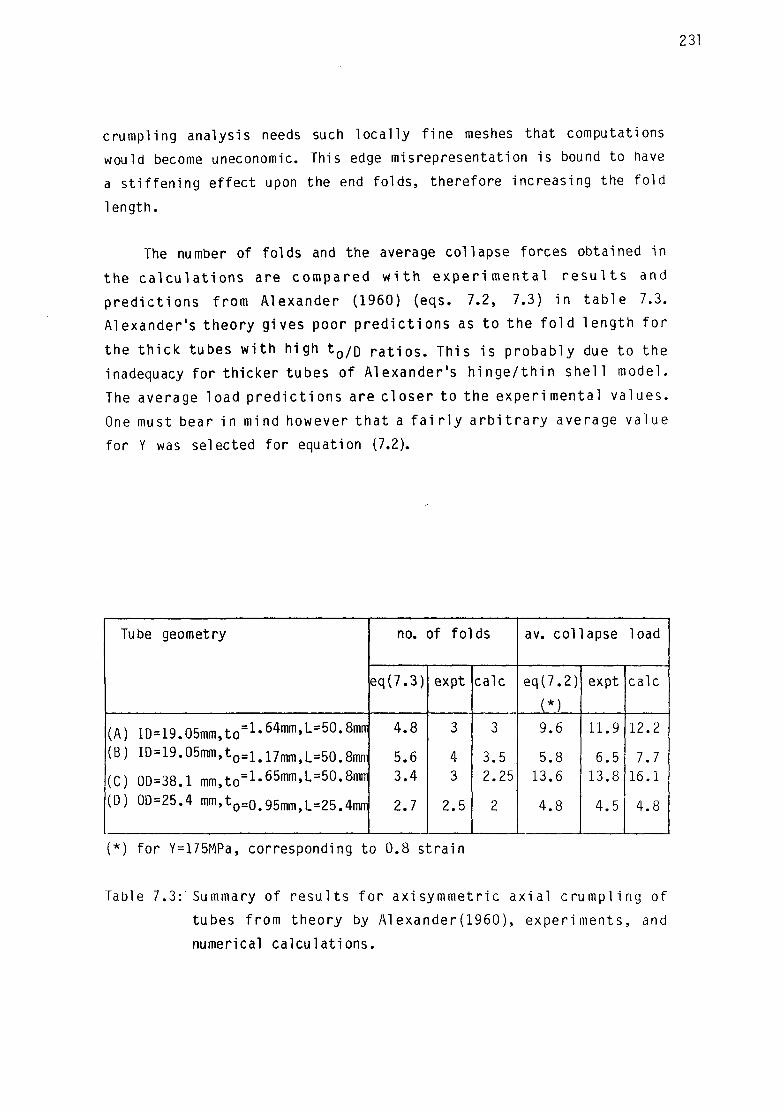
crumpling analysis needs such loca l l y f ine meshes that computations
would become uneconomic. This edge misrepresentation is bound to have
a s t i f f en ing ef fect upon the end fo lds , therefore increasing the fo ld
length.
The number of fo lds and the average collapse forces obtained in
the c a l c u l a t i o n s are compared w i t h e x p e r i m e n t a l r e s u l t s and
p r e d i c t i o n s f rom Alexander (1960) (eqs. 7.2, 7.3) i n t a b l e 7.3.
Alexander's theory gives poor p r e d i c t i o n s as t o the f o l d leng th f o r
the t h i c k tubes w i t h high t 0 / o r a t i o s . This i s probably due to the
inadequacy for th icker tubes of Alexander 's h i n g e / t h i n s h e l l model.
The average load p r e d i c t i o n s are c l ose r to the exper imenta l va lues.
One must bear in mind however t h a t a f a i r l y a r b i t r a r y average value
for Y was selected for equation (7.2).
Tube geometry
(A) ID=19.05mm,to=1-64mm 'L=50-8mr r
(B) ID=19.05mm,to=1#17mn i jL=50#8mr i l
(C) 0D=38.1 m m , t o = 1 - 6 5 m m ' L = 5 0 - 8 m i T
(D) 0D=25.4 mm,to = 0 .95m m 5 L = 2 5 > 4 m n i
no. of fo lds
eq(7.3)
4.8
5.6 3.4
2.7
expt
3
4 3
2.5
calc
3
3.5 2.25
2
av. col lapse load
eq(7.2)
(*) 9.6
5.8 13.6
4.8
expt
11.9
6.5 13.8
4.5
calc
12.2
7.7 16.1
4.8
(*) for Y=175MPa, corresponding to 0.8 s t ra in
Table 7.3:'Summary of r e s u l t s f o r axi symmetr ic a x i a l c rump l i ng of
tubes from theory by Alexander(1960), exper iments , and
numerical ca lcu la t ions .

Anal.
TUBE1
TUBE2
TUBE3
TUBE4
TUBE5
TUBE6
TUBE7
TUBE8
TUBE9
TUBE10
TUBE11
TUBE12
TUBE 13
TUBE14
TUBE15
TUBE16
TUBE17
TUBE18
TUBE19
TUBE20
Geom.
( + )
E
E
E
E
E
E
E
E
F
B
B
B
A
D
A
A
A
A
C
C
Mesh
(++)'
Coarse,60x3
Coarse,60x3
Coarse,60x3
Coarse,60x3
Coarse,60x3
Coarse,60x3
Coarse,60x3
Coarse,60x3
Coarse,100x3
Coarse,65x3
Coarse,65x3
Medium,130x3
Medium,90x3
Medium,80x3
Fine, 124X3
Medium,90x3
Coarse,45x3
Medium,90x3
Coarse,60x3
Fine, 124x4
Element
type
(&*)
MTQC
MTQC
MTQC
MTQC
MTQC
MTQ
MTQC
MTQC
MTQC
MTQC
MTQ
MTQC
MTQC
MTQC
MTQC
CST
MTQC
MTQ
MTQC
MTQC
Frict.
(W
0.0
0.1
0.2
0.3
0.2
0.2
0.2
0.2
0.2
0.2
0.2
0.2
0.2
0.2
0.2
0.2
0.2
0.2
0.2
0.2
Platen
veloc.
(m/s)
40(A)
40(4)
40 U )
40(4)
40
40
20
10
20
20
20
20
20
20
20
20
20
20
20
20
no of
folds
2
3
3
3
3
3
3
3
5
3
3
3 1/2
3
2
3
1/2
2 1/2
3
2
2 1/2
Avge.
Load P
[kN) (*)
10.2
11.7
11.4
11.4
10.5
9.9
10.0
9.8
10.2
7.2
7.3
7.7
12.9
4.8
12.2
22.2
14.3
11.5
14.8
16.1
CPU
(sec)
(**)
1040
1414
1364
962
1079
1196
1758
3474
5333
2263
3734
7167
3352
2664
8641
2346
1035
12882
1530
7732
(+) Geometry A: ID=19.05mm, t0=1.64mm, L=50.8mm
Geometry B: ID=19.05mm, t0=1.17mm, L=50.8mm
Geometry C: 00=38.10mm, t0=1.65mm, L=50.8mm
Geometry D: 00=25.40mm, tQ=0.95mm, L=25.4mm
Geometry E: 0D=38.10mm, t0=1.22mm, L=50.8mm
Geometry F: 0D=38.10mm, t0=1.22mm. L=88.9mm
(++) For c l ass i f i ca t i on of meshes see section 7.3.2.1
{&) Velocity was applied without i n i t i a l ramp for these cases
{&&) See section 4.2
(*) P = [JPdxj/L (**) CPU times on a CRAY-IS
Table 7.4: Detai ls of numerical analyses for axial tube collapse

The numerical model i s not cons t ra ined by beam or t h i n she l l
assumptions, and therefore f inds no problems in modelling the th ick
tubes, where in fact i t gives better predict ions. The load resul ts are
o v e r s t i f f i n a l l cases; however, f o r the second and t h i r d tubes in
t ab le 7.3 the r e l a t i v e l y la rge d i f f e r e n c e w i t h exper iment is due to
the shorter, s t i f f e r incomplete fo lds at the end of the analysis.
7.4 MEDIUM VELOCITY (176m/s) TUBE IMPACT ANALYSIS
The impact of medium v e l o c i t y hard and s o f t m i s s i l e s on
structures has been the object of some in teres t in the past few years.
Extensive programs of experimental research have been undertaken at
Meppen, FDG (e.g. Rudiger and Riech, 1983) and W i n f r i t h , UK (e.g.
Barr, 1983a, 1983b). The research is concerned wi th "medium" and "low"
veloci ty impact, for which s t ra in - ra te ef fects are moderate.
A crashing a i r c r a f t consists p r i nc ipa l l y of a soft tubular body
w i t h some sma l le r hard or semihard p a r t s . I t has been model led at
W i n f r i t h and Meppen by t u b u l a r capped s tee l m i s s i l e s w i t h added
masses, impact ing at v e l o c i t i e s between 150 and 300 m/s. In general
the impact of such missi les produced concertina type crumpling. The
axial d i rec t ion of the impact and the extensive crumpling produced has
prompted some one-di mensional empi r i c a l - n u m e r i c a l s o l u t i o n s (e.g.
Bignon and Riera (1979), Hurley (1983)). These s o l u t i o n s , however,
depend heavily on the in te rp re ta t ion of empir ical data from crushing
loads and s t r a i n - r a t e e f f e c t s on col lapse mechanisms, not providing
therefore true general predict ions.
The numerical procedures described in th i s thesis (chapter 4) are
sui table for modelling the extensive axisymmetric crumpling produced
by the impact of a tubular steel miss i le against a r i g i d surface. Such
an a n a l y s i s , corresponding to W i n f r i t h exper iment no. M i l l , i s
described here.
7.4.1 DESCRIPTION OF PROBLEM
The missile (fig. 7.44) consists of a thin spherical cap followed

234
makewei qh t 4 . «Kcj
V=!76m/s
L 2.5mm "> !'> i c k e r p i pc-
l"Ot-cj| mass |SK<
1,6mm t h i n [if; \ r, j p t)
Sbmrn 7 4 0 mm 6 2 5 mm
•1 A S'!;S ' ry
Node 3890 Cell 5693 Node 400 Cell 5671
FW
Figure 7.45s MESH FOR TUBULAR MISSILE CALCULATIONS ( G L N L R A L VIEW>

by a pipe and, e v e n t u a l l y , an end mass. The pipe i s composed of two
parts, each wi th a d i f f e ren t thickness and s l i g h t l y d i f f e ren t material
propert ies.
The m i s s i l e was cons t ruc ted of co ld r o l l e d m i l d s tee l sheet ;
apart from th i s f ac t , other e x p l i c i t material data were scarce, being
l imi ted to the values of the y i e l d stress and elongation at f a i l u r e :
thickness Yield stress Elongation at f a i l u r e
1.6 mm 308 MPa 29%
2 . 5 mm 270 MPa 24%
The m i s s i l e impacts the t a r g e t plane no rma l l y , w i t h an ax ia l
v e l o c i t y of 176 m/s. The t a r g e t plane i s assumed both r i g i d and
f r i c t i o n l e s s .
7.4.2 NUMERICAL IDEALIZATION
Because of the axisymmetric character of the problem, MTQC toro ida l
elements (sect . 4.2.3) can be used to represent the body. The mesh
cons is ted of 3901 nodes and 5771 t r i a n g u l a r plane c e l l s (2887 MTQC
elements) ( f i g u r e s 7.45 and 7.46). The mesh was prepared us ing two
quadr i la tera ls through the thickness of the spherical cap. In the tube
sect ion, three quadr i la tera ls through the thickness wi th approximate
shape r a t i o 2:1 were taken , in order to represent accu ra te l y the
concertina fo ld ing expected. For a small furthermost part of the tube
where bending was not expected, the mesh was coarsened to two and one
quadr i la tera ls through the thickness. The makeweight was represented
with larger so l id elements having the appropriate mass. The target was
modelled as a r i g i d , f r i c t i o n l e s s stonewal l .
The steel material was assumed to have a density of 7800 Kg/m3,
and an e l a s t i c - p l a s t i c s t r e s s - s t r a i n behaviour. The e l a s t i c par t i s
characterized by a Young's modulus of 210 GPa and a Poisson's ra t i o of
0.3.
The p l a s t i c i t y was described by a Von Mises Yield surface and an

236
^'"/'//////////////////////////////ST-
Figure 7.46, MESH FOR TUBULAR MISSILE CALCULATIONS (DETAIL OF TIP)
////////////"/////////
Figure 7.47, TUBULAR MISSILE IMPACT - VIEW OF TIP AT 0.1msec

associative law. However, the radius of the Von Mises cy l inder is not
constant but changes wi th p las t i c s t ra in and w i th s t ra in - ra te . At each
t ime, the e f fec t i ve stress at y i e l d is affected by a power law s t r a i n -
hardening and a power law c o r r e c t i o n f o r s t r a i n - r a t e s e n s i t i v i t y ,
according to the expression:
Y = A e n ( l +e m /B)
where A and n describe the hardening behaviour
for t0=i.6mm (thinner pipe) A=495 MPa, n=0.17
for t 0= 2 - 5 m m ( th icker pipe) A=470 MPa, n=0.17
8 and m represent the s t ra in - ra te s e n s i t i v i t y
for both cases B=40.4 sec-m, m=0.2
7.4.3 NUMERICAL RESULTS
The ana lys i s was performed on a PRIME 750 computer. I t was
pursued up t o a t ime of 2.5 msec, being i n t e r r u p t e d then because of
two reasons:
- the computer costs had become excessive, over 39 CPU days;
- fur ther deformation of the miss i le would only involve repe t i t i on of
the concertina fo ld ing mechanism already observed; not much addi t ional
information would be gained from the cont inuat ion of the analys is .
The number of computational cycles was 111336. Successive views
of the deformed mesh are presented in f igures 7.47 - 7.53 (deta i ls of
m i s s i l e t i p ) and 7.54 (general v iews) . I t can be seen t ha t a f t e r an
i n i t i a l stage in which the spherical cap buckled inwardly ( f i g . 7.47),
the res t of the deformat ion cons i s t s of the p i l i n g up of successive
concer t ina f o l d s (18 in t o t a l ) . A l l the f o l d s were produced in the
thinner tube sect ion, the th icker part not having being reached at the
time the analysis was stopped.
The resul tant of the contact forces between miss i le and stonewall
i s p l o t t e d i n f i g u r e 7.55 as a h i s t o r y of t i m e . The i n i t i a l p a r t , up
to 0.2 msec, corresponds to the buckling of the spherical cap, and is
cha rac te r i zed by being wery "no isy" . The remainder cons i s t s of a
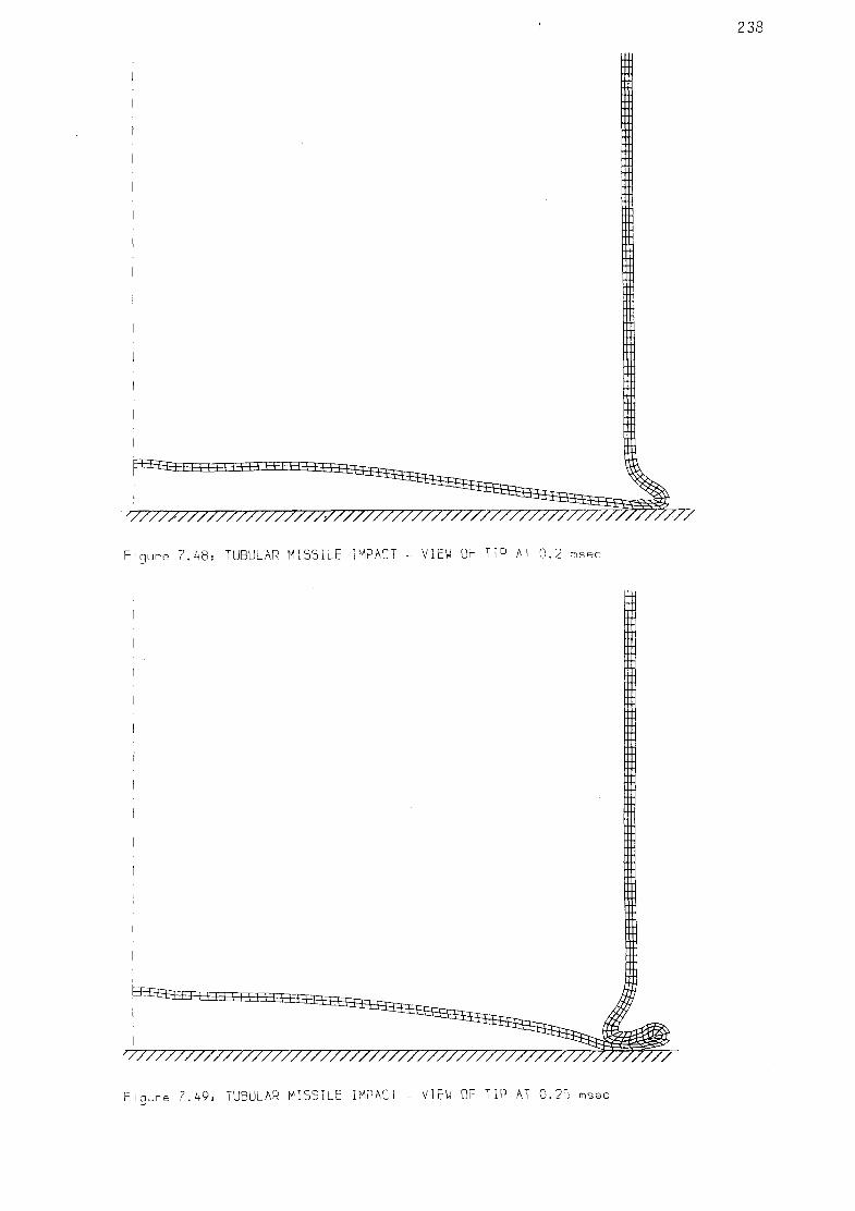
238
i n i i i n i T i i m i m=^s
V777777777V77777777777777777777777777777777777777777777777
F i g u r e 7 . 4 8 : TUBULAR MISSILE IMPACT - VIEW OF TIP AT 0 . 2 msec
'y//////77/7/7/7777777//77/////////777/////777/7777777///
F i q u r e 7 . 4 9 : TUBULAR MISSILE IMPACT - VIEW OF TIP AT 0 . 2 5 msec
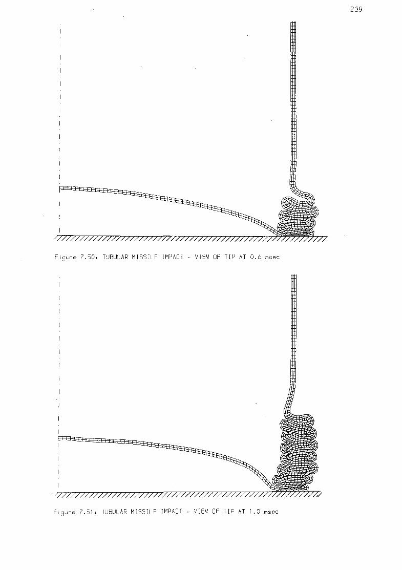
239
/777777777777777777777777777777777777777777777777,
F i g u r e 7 . 5 0 : TUBULAR MISSILE IMPACT - VIEW OF TIP AT 0 . 6 msec
h ± ± : 1 ^^3^_L_LJ_LL i j - £
^7777777777777777777777777777777777777777777777777777777777
F i g u r e 7.51= TUBULAR MISSILE IMPACT - VIEW OF TIP AT 1.0 msec

240
Figure 7.52: TUBULAR MISSIVE IMPACT - VIEW OF TIP AT 2.0 msec
Figure 7.55, TUBULAR MISSILE IMPACT - VIEW OF TIP AT 2.5 msec

241
+=0.00msec t=0 .20msec t = I . 0 0 m s e c t = 1 . 8 0 m s e c
t-=0. 04msec t=0 .40msec t = 1.20msec +=2.00msec
t=O. IOmsec t=0 .60msec += I .40msec l— t
t - -2 .20msec
+=0.15msec +=0.80msec += I .60msec l—I
"=2. 50msec
F i g u r e 7 . 5 4 : T u b u l a r m i s s i l e impac t - s u c c e s i v e g l o b a l v i ews o f de fo rmed mesh

1400
1200
1000
800
600
400
200
EXPERIMENT CALCULATION
Figure 7.55: TUBULAR MISSILE IMPACT - LOAD HISTORY ON TARGET
1000
800
600
400
200
~i 1 r i 1 1 r
EXPERIMENT CALCULATION
• <- -"I i_ j i_ _ i i i i _
0.00 0.20 0.40 0.60 0.80 1.00 1.20 1.40 1.60 1.80 2.00 2.20 2.40
T I me (msec)
Figure 7.56, TUBULAR MISSILE IMPACT - IMPULSE HISTORY

number of peaks, two per f u l l conce r t i na f o l d . For each f o l d two
hinges are formed: one external and one i n te rna l . The bending in these
hinges corresponds to the less s t i f f periods (val leys), whi le for the
per iods in between, the loads are t r a n s m i t t e d by the much s t i f f e r
axial compression mechanism (peaks).
The fo rce was i n t e g r a t e d w i t h respect to t i m e , o b t a i n i n g the
impulse h i s t o r y ( f i g u r e 7.56). This c o n s t i t u t e s a much smoother and
nearly l inear curve. I t indicates a f a i r l y constant collapse force.
V e l o c i t y h i s t o r i e s are p r e s e n t e d i n f i g u r e 7.57 f o r two
representative points. One corresponds to the back end of the m iss i l e ,
showing an approx imate ly constant average d e c e l e r a t i o n . The second
point corresponds to the folded sect ion, showing an i n i t i a l stage of
slow deceleration fol lowed by a sudden stoppage in the formation of
the f o l d , continuing at zero ve loc i ty thereaf ter .
F ina l l y , h is to r ies of e f fec t i ve stresses are given in f igure 7.58
f o r a po in t near to the nose which has su f fe red s u b s t a n t i a l p l a s t i c
deformations in the fo ld ing , and for another point near the back which
has behaved e l a s t i c a l l y , without reaching y i e l d .
7.4.4 DISCUSSION
The concer t i na ax isymmetr ic c rump l ing has been model led on a
large scale without any computational problems (apart from the cost) ,
proving the robustness of the numerical algori thms and computer code.
The sequent ia l f o l d i n g process i s apparen t l y yery s i m i l a r to the
mechanisms al ready discussed f o r q u a s i - s t a t i c a n a l y s i s . However,
cons iderab ly l a rge r c rush ing load l e v e l s were observed f o r medium
veloc i ty crumpling than for quas i -s ta t ic s i tua t ions .
The experiment no. M i l l at W in f r i t h produced 23 folds in the th in
sec t ion of the tube and 6 f u r t h e r 4- lobed f o l d s in the t h i c k e r
s e c t i o n , l eav ing an u n d i s t o r t e d tube leng th of 550 mm; con tac t t ime
was 9.5 msec (data from Hurley, 1983).
The average f o l d leng th obta ined in the exper iment from the

244
20
-20
-40
-60
-80
-100
-120
-140
-160
-180
i 1 1 r
Node 400 (in crumpled portion)
Node 3890 (back end of projectilejL
0.00 0.20 0.40 0.60 0.80 1.00 1.20 1.40 1.60 1.80 2.00 2.20 2.40
T i me (msec)
Figure 7.57s TUBULAR MISSILE IMPACT - VELOCITY HISTORIES
500
450 -
400
350 -
300
250
200
150
100 -
50
0.00 0.20 0.40 0.60 0.80 1.00 1.20 1.40 1.60 1.80 2.00 2.20 2.40
T I me (msec)
Figure 7.58, TUBULAR MISSILE IMPACT - STRESS HISTORIES

th inner pipe f ront section was
n"exp = 27.2 mm
This compares with an average value (based on 18 folds), obtained in
the calculations of
^calc = 25.5 mm
while the value obtained from equation (7.3) by Alexander (1960) is
fiAlex = 29.3 mm
I n i t i a l l y i t was at tempted to solve the problem w i t h a mesh of
MTQ e lemen ts ( s e c t . 4 .2 .2 ) . A l t h o u g h these e l e m e n t s worked
s a t i s f a c t o r i l y for low ve loc i ty crumpl ing analyses ( sec t i on 7.3.4.4),
they proved u n s u i t a b l e f o r t h i s problem in which the v e l o c i t y of
deformat ion i s s u b s t a n t i a l l y g rea te r . Tangl ing over of the mesh
occurred in the f o rma t i on of the f i r s t f o l d , producing a negat ive
volume in one of the t r i a n g u l a r c e l l s on the inner s ide of the f o l d
( f igs . 7.59a, 7.59b). This caused the computations to become unstable
immediately ( f i g . 7.59c).
Previously, s im i l a r problems had been often observed when using
Mixed D i s c r e t i z a t i o n procedures (MTQ i n 2-D, MTB in 3-D) f o r very
large deformat ion analyses, c o n s t i t u t i n g a drawback f o r these
procedures. I t was th i s par t i cu la r case which motivated the present
research to f ind a corrected element; t h i s element should preserve the
capab i l i t y for modelling incompressible p las t i c f low of the ex is t ing
Mixed Discret izat ion elements, but generating a greater resistance to
tangl ing over. The resul t was the corrected mixed elements (MTQC in 2-
D, MTPC in 3-D) presented in sec t ion 4.2.3, which have been used f o r
th i s analysi s.
The h i s t o r y of loads o b t a i n e d f r om the c a l c u l a t i o n s was
substant ia l ly "nois ier" than the exper imenta l h i s t o r y ( f i g u r e 7.55).
Two factors are the cause for th i s d i f ference. F i r s t l y the f i n i t e r ise
t ime for the load-cel l used in the experiments w i l l have probably made
i t miss some of the very f a s t t r a n s i e n t s , a l though u n f o r t u n a t e l y no
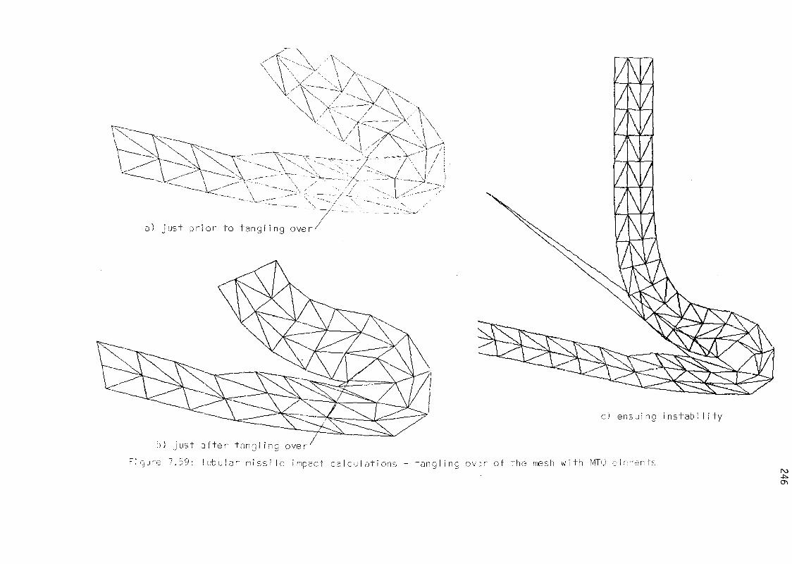
/C\ \ X
/ \
T^-\Ax \ \ Ar / W A
-A/ X> \
A *f~.
3 !
A
/
- -
a) j u s t p r i o r t o t a n g l i n g o v e r -
b) j u s t a f t e r t a n g l i n g o v e r '
F i g u r e 7 .59 : T u b u l a r m i s s i l e impac t c a l c u l a t i o n s - t a n g l

data are a v a i l a b l e t o q u a n t i f y t h i s hypothes is . Secondly, the great
number of a r t i f i c i a l contact springs in the numerical model may have
introduced some addit ional noise in to the e las t i c folded region, which
work ing in a l i n e a r n o n - d i s s i p a t i v e reg ime, is n a t u r a l l y "no isy" on
i t s own.
However, the time-average values of numerical and experimental
loads proved to be remarkably close:
^expt = 338.4 kN
Pcalc = 3 2 9 - 6 k N
These averages were taken for the period comprised between 0.2 and 2.5
msec, which corresponds to the ax isymmet r i c c rump l ing of the tube
af ter the i n i t i a l buckling of the spherical cap.
The dynamic i n e r t i a force from the decelerat ion of the folds was computed according to eqn. (7.8); the ve loc i ty v( t ) introduced in t h i s
equat ion was the h i s t o r y of v e l o c i t i e s at the top node (node 3890,
f i g u r e 7.57). The t ime average of t h i s i n e r t i a f o r c e , again r e f e r r e d
to the period 0.2-2.5 msec, was
Pi = 179.3 kN
which, subs t rac ted from the value of the t o t a l f o r c e , P=329.6 kN,
according to eqn. (7.5) leaves an average crushing force of
pc = 150.3 kN
From these values i t i s apparent t h a t the dynamic e f f e c t s were
important for t h i s problem, the i n e r t i a forces being approximately 1/2
of the ove ra l l t o t a l f o r c e s , and of the same order as the forces
or ig inated by the crumpling process i t s e l f .
I t is not possible to compute precisely the mean crushing force
resu l t ing from experiment as no data ex is t for ve loc i ty h is tor ies of
the miss i le during the impact. However, the fo l low ing considerations
support the assumption of the exper imenta l and numerical c rush ing
forces being very s im i l a r . According to eqn. (7.9) the crushing force,

pc , may be expressed as the di f ference between the to ta l force, P, and
the i ne r t i a force, P # i t was seen above that the di f ference between
experimental and numerical average to ta l forces was small (2.6%). On
the other hand, f o r the per iod ana lyzed, the dece le ra t i on has been
small (from 176m/s to 152m/s, see f i g . 7.57). The close match between
numerical and experimental impulse h is to r ies ( f i g . 7.56) suggests that
a s im i l a r l y small deceleration would have happenned in experiment. As
the i n e r t i a f o r c e , P^ depends on the v e l o c i t y (eqn. 7.8), i t may be
presumed t h a t exper imenta l and numerical c rush ing fo rces w i l l be
s im i la r w i th in an error of approximately 10%.
This "medium" ve loc i ty crushing force is considerably larger than
that obtained from s ta t i c tests performed on ident ica l tubes (Hurley,
1983), which y ie lded a value of
pstat = 6 1 kN
This s ta t i c value is consistent wi th the generally good quas i -s ta t i c
load p r e d i c t i o n s from eqn. (7.2) (Alexander, 1960). Cons ider ing an
average value of Y = 476 MPa, which corresponds to 0.8 s t r a i n ,
pAlex = 7 1 k N
Of th i s di f ference (150.3kN medium ve loc i t y , 61kN quas i - s ta t i c ) ,
the s t ra in - ra te material hardening accounts only fo r a minor part . The
s t ra in - ra te enhancement may be approximated as fo l lows.
- time for the formation of one complete f o l d (two hinges):
t = (h-2tQ)/v = (27.2-3.2)10~3m/(170m/s) = 1.41xl0"4 (sec.)
- average s t ra i n - ra te :
A6= 2x0.8 = 1.6
e= A- = l . lx lO 4 (sec-1) At
- s t ra in - ra te enhancement fac to r :
1+ em /8 = l + ( l . l x l 0 4 ) ° - 2 / 4 0 . 4 = 1.16,

which corresponds to an increase of only 16%.
Even al lowing for errors in these s imp l i f i ed considerat ions, the
dif ference between quasi -s tast ic and medium ve loc i ty crushing loads is
too la rge (approx. 100%) t o be exp la ined by s t r a i n - r a t e m a t e r i a l
hardening alone. This resul t is extremely in te res t ing and suggests an
i n h e r e n t l y s u b s t a n t i a l l y g rea te r energy d i s s i p a t i o n f o r medium
v e l o c i t y tube c r u m p l i n g , even f o r r a te - i nsens i t i ve mater ia ls . I t is
a l l the more notab le s ince e x t e r n a l l y no apparent d i f f e r e n c e s are
apprec ia ted between the crumpled geometr ies f o r low and medium
veloc i ty impact.
An exp lana t ion f o r t h i s may be found in the pronounced non-
l i n e a r i t y of the process. A f i n a l geometry which i s s u b s t a n t i a l l y
the same may be a r r i v e d at by d i s t i n c t pa ths , assoc ia ted w i t h
d i f f e ren t amounts of dissipated energy.
7.5 CONCLUSIONS
1- Tubes subjected to axial collapse are e f f i c i e n t energy absorbers
for impact s i tua t ions . Experimental knowledge from the bahaviour of
Aluminium tubes under quas i -s ta t ic axial col lapse was obtained from
t e s t s c a r r i e d out main ly by Ghani (1982). Microhardness t e s t s in
sect ions of the crumpled tubes a l lowed the de te rm ina t i on of y i e l d
s t ress (Y) d i s t r i b u t i o n s around the f o l d s . These d i s t r i b u t i o n s were
useful as a check of the numerical p red ic t ions .
2- The numerical mode l l i ng of q u a s i - s t a t i c , ax isymmet r ic ax ia l
collapse of tubes was approached wi th the non-l inear e x p l i c i t F in i te
D i f f e rence code (chapter 4). The numer ica l p r e d i c t i o n s ( l o a d -
displacement curves , deformed geomet r ies , s t ress d i s t r i b u t i o n s )
compared well w i th experiment. The numerical code used const i tu tes a
robust s o l u t i o n method f o r mode l l i ng what i s a h i g h l y complex non
l i n e a r process, w i t h very la rge s t r a i n s and a r b i t r a r y tube- tube and
tube-platen contacts. The simple, sound material model employed, based
on Von Mises i s o t r o p i c p l a s t i c i t y (chapter 6 ) , a lso performed
exce l len t l y .
3- An e x p l i c i t (dynamic) s o l u t i o n method was applied successful ly
for modelling the quas i -s ta t ic col lapse, using ve loc i ty scal ing in a
contro l led manner.
4- The numer ical model proved s e n s i t i v e to mesh r e f i n e m e n t ,
specia l ly in short tubes wi th few folds in the crumpling mechanism,
for which end ef fects are important. An overal l tendency for ove rs t i f f
predict ions ( fo ld lengths too large) was detected. Convergence towards
experimentally observed behaviour was achieved with mesh refinement.
5- The choice of appropriate elements for the numerical model was
essential for successful predic t ions. CST elements (section 4.2.1) are
t o t a l l y u n s u i t a b l e . CMTQ elements (sec t ion 4.2.3) prov ided the best
results and the most robust meshes.
6- A medium veloc i ty (176m/s) impact of a long tubular p r o j e c t i l e ,
ocassioning large-scale crumpling, was modelled successful ly, a lbe i t
at a high cost i n computer resources. Resul ts compare we l l w i t h
exper iment , and i n d i c a t e s u b s t a n t i a l l y g rea te r l e v e l s of energy
d iss ipat ion in the crumpling process than for quas i -s ta t i c co l lapse.

CHAPTER 8
CONCLUSIONS AND SUGGESTIONS FOR FURTHER RESEARCH
8.1 CONCLUSIONS
8.2 SUGGESTIONS FOR FURTHER RESEARCH
8.2.1 Theoretical and numerical developments
8.2.2 Additional applications

8.1 CONCLUSIONS
1. Exp l i c i t F in i te Difference techniques, as used in th i s work, are
advantageous for non- l inear, short durat ion t ransient analysis (wave
propagation type). They can be also useful in slow loading but steeply
non - l i nea r problems, in order to take advantage of t h e i r robustness
and ease of implementation. In general, theoret ica l so l id mechanics
concepts and equations can be implemented s t ra igh t fo rward ly . Many of
the more r igorous s t ress update procedures necessary f o r i m p l i c i t
methods need not be used, as t ime-steps are res t r i c ted to very small
values for s t a b i l i t y . A Lagrangian mesh together wi th a Cauchy stress
- v e l o c i t y s t r a i n f o r m u l a t i o n are app rop r i a te f o r low - medium
ve loc i ty , large s t ra in e l as t i c - p l as t i c problems wi th contacts.
2. Meshes based on constant s t r a i n t r i a n g l e s or t e t r ahed ra (CST)
prov ide unacceptable r e s u l t s f o r incompressible p las t i c f low. Mixed
Discret izat ion procedures based on averaging the vo l ume t r i c s t r a i n s
from several t r i a n g l e s / t e t r a h e d r a (Mart i and Cundall, 1982) provide
accurate predict ions and are easi ly implemented in to computer codes;
however, t a n g l i n g over of the mesh can occur in problems w i t h very
la rge d i s t o r t i o n s . A c o r r e c t i o n method i s proposed here (sec t ion
4.2.3) f o r Mixed D i s c r e t i z a t i o n procedures, which main ta ins t h e i r
a b i l i t y fo r accurate p las t i c f low model l ing, recovering the resistance
to t a n g l i n g over of CST meshes. Hence, a more robust and equa l l y
accurate a l te rna t i ve to Mixed D iscre t iza t ion is obtained.
3. Tension tests are a simple and re l i ab le means for obtaining large
s t r a i n ma te r i a l s t r e s s - s t r a i n behaviour (chapter 6). Exper imental
da ta , together w i t h some t h e o r e t i c a l i n t e r p r e t a t i o n and r e s u l t s of
numerical s imulat ion tes ts , allowed a representative cons t i t u t i ve law
for Aluminium to be establ ished. A simple Von Mises p l a s t i c i t y model
wi th power law hardening was employed. Results fo r more complex tube
c rump l ing s imu la t i ons showed the appropr ia teness of t h i s m a t e r i a l
model.
4. Numerical mode l l i ng of tube co l l apse mechanisms through
axisymmetric sequential crumpling was successful ly achieved (chapter
7) wi th the Exp l i c i t F in i te Difference code developed (chapter 4). The
contact algorihtms employed were successful and e f f i c i e n t in modell ing

the i n t e r f a c e between tube f o l d s and between tube and p l a t ens . The
resu l t ing load-displacement curves and deformed geometr ies compare
we l l w i t h exper imenta l data f o r q u a s i - s t a t i c tube c o l l a p s e . Stress
d i s t r i b u t i o n s i n c r u m p l e d t ube s e c t i o n s were compared w i t h
experimental data derived from microhardness t es t s , wi th good resu l ts .
The i n f l u e n c e of some impor tan t aspects of the numerical model was
ascertained:
- the model behaviour is ove rs t i f f (folds too long) i f the mesh is not
s u f f i c i e n t l y re f ined ;
- the choice of app rop r ia te element types (CMTQ, sec t . 4.2.3) was
essential fo r e f f i c i e n t and successful model l ing;
- The ve loc i ty scal ing used (wi th in the low ve loc i ty regime) allowed
mode l l i ng of a q u a s i - s t a t i c phenomenon w i t h an e x p l i c i t , dynamic
procedure;
- end e f f e c t s (deformat ion and f o l d i n g at tube edges) may have a
s i g n i f i c a n t i n f l u e n c e in some cases, being d i f f i c u l t t o represent
appropriately wi th in a la rger , global model.
5. Analysis of a steel tube medium ve loc i ty (176 m/s) impact (sect.
7.4) provided resul ts which compare well wi th experimental data. The
deformed geometry was s i m i l a r t o the low v e l o c i t y case, but the
crushing force was found to be s i g n i f i c a n t l y higher.
6. Computational costs f o r tube co l l apse s i m u l a t i o n s are h i gh ,
although affordable for special ized safety or impact ca lcu la t ions .
8.2 SUGGESTIONS FOR FURTHER RESEARCH
A number of options are avai lable for researchers interested in
the topics dwelt upon in t h i s thes is . Theoretical work along some of
the l ines suggested below would enhance the a p p l i c a b i l i t y of numerical
s i m u l a t i o n procedures to n o n - l i n e a r processes. Other suggest ions
invo lve the use of s i m i l a r numerical methods as proposed here,
widening the f i e l d of appl icat ions to other non-l inear problems.

8 .2 .1 THEORETICAL AND NUMERICAL DEVELOPMENTS
The choice of an o b j e c t i v e s t ress ra te f o r l a rge s t r a i n ana l ys i s
i s not un i que ( s e c t i o n 2 .5 .1) . G e n e r a l l y , t h e use of a p a r t i c u l a r
s t ress ra te i s pos tu la ted and app l i ed to the e x i s t i n g ma te r i a l data.
I t wou ld be u s e f u l t o s t udy t h e i n f l u e n c e of t he d i f f e r e n t c h o i c e s
a v a i l a b l e , b o t h i n t h e o r e t i c a l t e r m s and f o r t h e p r a c t i c a l
i m p l i c a t i o n s in la rge s t r a i n eng ineer ing ana lyses .
The ma te r i a l models employed here are r e s t r i c t e d to s imp le Von
Mises p l a s t i c m a t e r i a l s w i t h hardening. This cou ld be extended to more
s o p h i s t i c a t e d m a t e r i a l models ( s e c t . 2.2.7) a p p r o p r i a t e f o r m e t a l s
( d i s t o r t i o n of y i e l d s u r f a c e , y i e l d and f a i l u r e s u r f a c e s ) , s o i l s
( d i l a t a t i o n , n o n - a s s o c i a t i v i t y , n o n - c y l i n d r i c a l y i e l d s u r f a c e s ,
m u l t i p l e s u r f a c e i d e a l i z a t i o n s ) or c o n c r e t e ( c r a c k i n g and f a i l u r e
c r i t e r i a , n o n - c y l i n d r i c a l y i e l d s u r f a c e s ) .
More r i g o r o u s a l t e r n a t i v e s e x i s t t o t h e s i m p l e p l a s t i c r a d i a l
r e t u r n and s t r e s s upda te a l g o r i t h m s employed here ( s e c t i o n s 4 .5 .2 ,
4 .5 .4 ) . I t wou ld be u s e f u l t o s t u d y t h e a p p l i c a b i l i t y and p r a c t i c a l
i n f l uence of these a l t e r n a t i v e s w i t h i n e x p l i c i t and i m p l i c i t codes.
E lement by E lement methods (Hughes, L e v i t and Winget (1983b) ,
O r t i z , P insky and T a y l o r (1983)) a re p r o m i s i n g new a l t e r n a t i v e s f o r
n o n - l i n e a r t r a n s i e n t a n a l y s i s . The main problem seems to be accuracy,
and pub l ished a p p l i c a t i o n s are r e s t r i c t e d to smal l academic examples.
Such a l g o r i t h m s can be i m p l e m e n t e d w i t h o u t much e f f o r t i n t o t h e
a r c h i t e c t u r e of an e x p l i c i t code, in order to study t h e i r behaviour in
p r a c t i c a l terms f o r l a rge scale eng ineer ing computa t ions .
For p e n a l t y method c o n t a c t m o d e l s , f u r t h e r r e s e a r c h w o u l d be
u s e f u l i n o r d e r t o i n c r e a s e t h e r o b u s t n e s s and e f f i c i e n c y of t h e
a l g o r i t h m s . Th i s c o u l d i n c l u d e a d a p t a t i v e methods f o r d e t e r m i n i n g
c o n t a c t s t i f f n e s s e s , and i m p r o v e d search a l g o r i t h m s f o r a u t o m a t i c
de tec t i on of c o n t a c t s .

E x p l i c i t t ime i n t e g r a t i o n procedures could be used much more
e f f i c i e n t l y f o r s t a t i c or q u a s i - s t a t i c problems through the use of
adapta t ive dynamic r e l a x a t i o n techniques (Underwood, 1983). In f ac t ,
r e l a x a t i o n techniques are a lso being proposed l a t e l y f o r use in
equa t i on - so l v i ng w i t h i n i m p l i c i t methods (e.g. Belytschko, 1983). I t
i s poss ib le t h a t a r e l a x a t i o n a l g o r i t h m cou ld be found t h a t was
appropr ia te both f o r i m p l i c i t e q u a t i o n - s o l v i n g and f o r e x p l i c i t
dynamic r e l a x a t i o n . This would make poss ib le the h i gh l y d e s i r a b l e
combinat ion of e f f i c i e n t e x p l i c i t and i m p l i c i t solut ion techniques
w i th in the same algori thm and computer code.
8.2.2 ADDITIONAL APPLICATIONS
The thermomechanical coupling algor i thm developed can be readi ly
applied to study coupled phenomena, such as metal forming processes
wi th generation of heat from p las t i c work and the consequent thermal
stresses and material softening.
Further use can be made of tension t es t s , coupled wi th numerical
s imulat ions, fo r more deta i led invest igat ions in to material behaviour
and f a i l u r e modes in me ta l s , and e f f e c t s such as the i n f l u e n c e of
pores and mechanisms fo r void growth.
The numerical techniques employed here could also be used for the
study of l a t e r a l compression of tubes or tube assembl ies (sect .
7.2.3.1), tube i nve rs i on (sect . 7.2.3.4), or diamond f o l d co l l apse (3-
D model) (sect. 7 .2 .3 .3 ) .
The c rush ing fo rce f o r medium v e l o c i t y impact (sec t . 7.4) was
s i g n i f i c a n t l y h igher than t h a t expected f o r low v e l o c i t y or q u a s i -
s t a t i c c o l l a p s e , both from t h e o r e t i c a l and experimental resu l ts . I t
would be very in te res t ing to study, e x p e r i m e n t a l l y and n u m e r i c a l l y ,
the i n f l uence of impact v e l o c i t y on c rush ing mechanisms, both f o r
ra te- insens i t i ve and rate-dependent mater ia ls .

REFERENCES
ALEXANDER, J.M. (1960): 'An approximate ana lys i s of the co l l apse of
t h i n c y l i n d r i c a l s h e l l s under ax ia l l o a d i n g ' , Quart. J . Mech. Appl .
Math., Vol X I I I (1), pp 10-15.
AL-HASSANI , S .T .S, JOHNSON, W., and LOWE, W.T. ( 1 9 7 2 ) :
' C h a r a c t e r i s t i c s of i n v e r s i o n tubes under ax ia l l o a d i n g ' , J . Mech.
Eng. Sc i . , Vol 14, pp 370-381.
ANDREWS, K.R.F., ENGLAND, G.L. and GHANI, E. (1983): ' C l a s s i f i c a t i o n
of the ax ia l co l l apse of c y l i n d r i c a l tubes under q u a s i - s t a t i c
load ing ' , I n t . J . Mech. S c i . , Vol 25(9-10), pp 687-696.
ARGYRIS, J.H. and KELSEY, S. (1954): 'Energy thorems and s t r u c t u r a l
ana lys i s ' , a i r c r a f t eng., Oct. 1954.
BARR, P. (1983a): 'Studies of the e f f e c t s of m i s s i l e impacts on
s t ruc tu res ' , Atom (UKAEA), Vol 318(Apr i l ) .
BARR, P. (1983b): 'Co l laps ing s tee l m i s s i l e impact on concre te
t a r g e t ' , pr ivate communication, UKAEE Winf r i th (UK).
BATHE, K.J., RAMM, E. and WILSON, E.L. (1975): ' F i n i t e Element
formulations for large deformation dynamic analys is ' , I n t . J. Numer.
Meth. Eng., Vol 9, pp 353-386.
BATHE, K.J. and WILSON, E.L. (1976): 'Numerical methods in F i n i t e
Element ana lys i s ' , Prent ice-Hal l , New Jersey.
BELYTSCHKO, T. (1978): ' E x p l i c i t t i m e - i n t e g r a t i o n of s t r u c t u r e -
mechanical systems', in 'Advanced Structural Dynamics', J. Donea ed.,
Applied Science publ ishers, London, pp 97-122.

BELYTSCHKO, T. (1983): 'An overview of s e m i d i s c r e t i z a t i o n and t ime
i n t e g r a t i o n procedures ' , in 'Computat ional methods f o r t r a n s i e n t
a n a l y s i s ' , eds. T. Belytschko and T.J.R. Hughes, No r th -Ho l l and ,
Amsterdam.
BELYTSCHKO, T., HOLMES, N. and MULLEN, R. (1975) : ' E x p l i c i t
i n t e g r a t i o n - s t a b i l i t y , s o l u t i o n , p r o p e r t i e s , c o s t ' , i n ' F i n i t e
Element Analysis of Nonlinear Structural Behaviour', T. Belytschko et
a l . eds., ASME AMD-Vol 14, N.Y., pp 1-23.
BELYTSCHKO, T. and KENNEDY, J.M. (1978): 'Computer models f o r
subassembly s imu la t i on ' , Nucl. Eng. Design, Vol 49, pp 17-38.
BELYTSCHKO, T. and SCHOEBERLE (1975): 'On the uncondit ional s t a b i l i t y
of an i m p l i c i t algori thm fo r nonlinear s t ruc tura l dynamics', J. Appl.
Mech., Vol 42, pp 865-869.
BELYTSCHKO, T. and TSAY, C.S. (1982): 'WHAMSE - A program f o r t h r e e -
dimensional nonl i near s t r u c t u r a l dynamics ' , Nor thwestern U., 111. ,
rept . NP-2250.
6ERTH0LF, L.D. and BENZLEY, S.E. (1968): 'TOODY I I - A computer
program f o r two-dimensonal wave p ropaga t i on ' , SC-RR-68-41, Sandia
Laboratories, Albuquerque, New Mexico.
BIGNON, P. and RIERA, J.D. (1979): ' V e r i f i c a t i o n of methods of
ana lys is f o r s o f t m i s s i l e impac t ' , In forme de l a b o r a t o r i o CT-6/79,
Curso de posgraduacao em Engenheria c i v i l , U. Rio Grande do S u l ,
B raz i l .
BILLINGTON, E.W. and TATE, A. (1981): 'The physics of de fo rmat ion and
f l o w ' , McGraw-Hill, New York.
BODNER, S.R. and SYMONDS, P.S. (1960): ' P l a s t i c de fo rmat ion in impact
and impu l s i ve load ing of beams', in ' P l a s t i c i t y ' , E.H. Lee and P.S.
Symonds eds., Pergamon press, N.Y., pp 488-500.
BRIDGMAN, P.W. (1944): 'The s t ress d i s t r i b u t i o n at the neck of a
tens i le specimen', Trans. Amer. Soc. Metals, Vol 32, pp 553-574.

BRIDGMAN, P.M. (1945): 'E f f ec t s of high h y d r o s t a t i c pressure on the
p l a s t i c p rope r t i es of me ta l s ' , Rev. of Modern Phys., Vol 17(1), pp 3-
14.
BRIDGMAN, P.W. (1952): 'Studies in la rge p l a s t i c f l ow and f r a c t u r e ' ,
McGraw-Hill, New York.
CARSLAW, W.S. and JAEGER, J.C. (1947): 'Conduction of heat in s o l i d s ' ,
Clarendon press, Oxford.
CHEN, W.H. (1971): 'Necking of a bar ' , I n t . J . So l ids & S t r u c t . , Vol
7(7) , pp 685-717.
CLOUGH, R.W. (1960): 'The f i n i t e element in plane s t ress a n a l y s i s ' ,
Proc. 2nd ASCE Conf. Electronic Computation, Pit tsburgh Pa., Sept.
CLOUGH, R.W. and PENZIEN, J. (1975): 'Dynamics of s t ruc tures ' , McGraw-
H i l l , Tokyo.
COTTRELL, A. (1975): 'An i n t r o d u c t i o n to m e t a l l u r g y , 2nd ed . ' , Edward
Arnold, London.
COURANT, R. (1943): 'Var iat ional methods for the solut ion of problems
of equi l ibr ium and v i b r a t i o n s ' , B u l l . Amer. Math. Soc. 49, pp 1-23.
COURANT, R., FRIEDRICHS, K. and LEWY, H. (1928): 'On the p a r t i a l
d i f f e r e n t i a l equations of mathematical physics', Math. Ann., Vol 100,
pp 32-74.
CRUSE, T.A. (1969) : ' N u m e r i c a l s o l u t i o n s in t h ree -d imens iona l
e l a s t o s t a t i c s ' , I n t . J . Solids & S t ruc t . , Vol 5, pp 1259-1274.
CUNDALL, P.A. and MARTI, J. (1979): 'Some new developments in d iscrete
numerical methods for dynamic modelling of jo in ted reck masses', 1979
RETC proceedings, chpt. 84, pp 1466-1484.
CURNIER, A. (1984): 'A theory of f r i c t i o n ' , I n t . J . So l ids & S t r u c t . ,
Vol 20(7), pp 637-647.

DAFALIAS, Y.F. (1983): 'Corotational rates for kinematic hardening at
large p las t ic s t r a i n s ' , J . Appl. Mech., Vol 50, pp 561-565.
DAVIDENKOV, N.N. and SPIRIDINOVA, N.I. (1946): 'Ana lys is of the s t a te
of s t ress in the neck of a tens ion specimen' , Proc. Amer. Soc. f o r
tes t ing Mater., Vol 46, pp 1147-1158.
DE ROUVRAY.A., ARNADEAU,F., DUBOIS,J., CHEDMAIL,J.F. and HAUG,E.
(1984): 'Numerical techniques and exper imenta l v a l i d a t i o n s f o r
indus t r ia l appl icat ions ' , in 'Structural Impact and Crashwor th iness ' ,
Vol 1 , G.A.O. Davies ed . , pp 193-242.
DERUNTZ, J.A. and HODGE, P.G. (1963): 'Crushing of a tube between
r i g i d p la tens ' , J . Appl. Mech., Vol 30, pp 391-395.
DIETER, G.E. (1976): 'Mechanical M e t a l l u r g y , 2nd ed . ' , McGraw-H i l l ,
New York.
DONEA, J., FASOLI-STELLA, P. and GIULIANI, S. (1977): 'Lagrangian and
Eu ler ian F i n i t e Element techniques f o r t r a n s i e n t f l u i d - s t r u c t u r e
i n t e r a c t i o n prob lems' , Trans. 4th SMIRT conf . , paper 61 /2 , San
Francisco, Aug. 1977.
DOSTAL, M., PHELAN, P., and TRBOJEVIC, V.M. (1985): 'Ana lys is of an
acc identa l drop of LMFBR i n t e r m e d i a t e heat exchanger1, I n t . Mtg. on
fast breeder reactor safety, Knoxvi l le (Tennessee), Apr. 1985.
DRUCKER, D.C. (1951): 'A more fundamental approach to p las t i c s t ress-
s t r a i n r e l a t i o n s ' , Proc. 1st U.S. Nat. Congress Appl . Mech. (Chicago
1951), pp 487-491.
FLANAGAN,. D.P. and BELYTSCHKO, T. (1981a): 'Simultaneous re laxat ion in
s t r u c t u r a l dynamics ' , J . Eng. Mech. D iv . (ASCE), Vol 107(Dec.),pp
1039-1055.
FLANAGAN, D.P. and BELYTSCHKO, T. (1981b) : 'A u n i f o r m s t r a i n
hexahedron and quadr i la tera l w i th orthogonal hourglass con t ro l ' , In t .
J . Numer. Meth. Eng., Vol 17, pp 679-706.

hUNG, Y.C. (1965): 'Foundations of s o l i d mechanics' , P r e n t i c e - H a l l ,
New Jersey.
GARCIA, F. (1981) : 'Formu1ac i on del metodo de las ecuaciones
integrales de contorno en e lastop last ic idad t r id imens iona l ' , Doctoral
thes is , ETSI Indus t r ia les , U. Pol i tecnica Madrid.
GHANI, E. (1982) : ' S t a t i c and dynamic c o l l a p s e b e h a v i o u r o f
cy l i nd r i ca l tubes and tube assemblies', Ph.D. Thesis, Dept. C iv i l Eng.
King's C o l l . , U. of London.
GIULIANI, S. (1982): 'An a l g o r i t h m f o r cont inuous rezoning of the
hydrodynamic gr id in Arb i t ra ry Lagrangian-Eul e r i an computer codes' ,
Nucl. Eng. Design, Vol 72, pp 205-212.
GOICOLEA, J.M. (1985a): 'PR2D - An E x p l i c i t F i n i t e D i f f e r e n c e Non
l i n e a r Thermo-mechanical code. User's gu ide ' , Dept. of C i v i l Eng.,
King's C o l l . , U. of London, rept . CE-85-01
GOICOLEA, J.M. (1985b): 'PR2DPL - A program for mesh p l o t t i ng (user's
gu ide ) ' , Dept. C i v i l Eng., King's C o l l . , U. of London, r ep t . CE-85-02.
GOICOLEA, J.M. (1985c): 'CURVA - A program f o r graph drawing (user 's
gu ide) ' , Dept. C i v i l Eng., King's C o l l . , U. of London, r ep t . CE-85-03.
GOUDREAU, G.L. and HALLQUIST, J.O. (1982): 'Recent developments in
large-scale Lagrangian Hydrocode technology', Comp. Meth. Appl. Mech.
& Eng., Vol 33, pp 725-757.
GREEN, E.H. and NAGHDI, P.M. (1965): 'A general theory of an e l a s t i c -
p las t ic continuum', Arch. Rat. Mech. Anal. 18.
GUIST, L.R. and MARBLE, D.P. (1966): 'Predict ion of the inversion load
of a c i r cu la r t ube ' , US NASA technical note TN D-3622.
HALLQUIST, J.O. (1979): 'NIKE2D: An i m p l i c i t , f i n i t e de fo rmat ion
F in i te Element code for analyzing the s ta t i c and dynamic response of
two-d imens iona l s o l i d s ' , Lawrence L ivermore l a b o r a t o r y , U. of
Ca l i fo rn ia , rept . UCRL-52678.
HALLQUIST, J.O. (1982a) : 'Use r ' s manual f o r DYNA2D', Lawrence
Livermore laboratory, U. of Ca l i f o rn ia , rept. UCID-18756.
HALLQUIST, J.O. (1982b): ' Theore t i ca l manual f o r DYNA2D', Lawrence
Livermore laboratory, U. of Ca l i f o rn ia , rept . UCID-19401.
HALLQUIST, J.O. (1982c): 'DYNA3D user 's manual (non l inear dynamic
ana lys is of s o l i d s in t h ree d i m e n s i o n s ) ' , Lawrence L i v e r m o r e
laboratory, U. of Ca l i f o rn ia , rept . UCID-19592.
HALLQUIST, J.O., WERNE, R.W. and WILKINS, M.L. (1977): d i scuss ion t o
" H i g h - v e l o c i t y impact c a l c u l a t i o n s in th ree d imensions" by G.R.
Johnson (1977), J . Appl. Mech., Vol 99(4), pp 793-794.
HANCOCK, S.L. (1976): ' F i n i t e D i f f e rence equations for PISCES-2DELK',
Physics Internat ional company report TCAM-76-2
HERNALSTEEN, P. and LEBLOIS, L.C. (1976): 'The use of energy absorbers
to protect structures against impact loading' , Nucl. Eng. Design, Vol
37, pp 373-406.
HERRMANN, W. and BERTHOLF, L.D. (1983): ' E x p l i c i t Lagrangian F i n i t e
D i f f e rence methods', in ' C o m p u t a t i o n a l Methods f o r T r a n s i e n t
Ana l ys i s ' , T. Belytschko and T.J.R. Hughes eds., No r t h -Ho l l and ,
Amsterdam.
HIBBIT, H.D., MARCAL, P.V. and RICE, J.R. (1970): 'A F i n i t e Element
formulat ion for problems of large st ra ins and displacements', In t . J.
Solids & S t ruc t . , Vol 6, pp 1069-1086.
HILL, R. (1950): 'The mathemat ical theory of p l a s t i c i t y ' , Clarendon
press, Oxford.

HIRT, C.W., AMSDEN, A'.A. and COOK, J .L . (1974) : 'An A r b i t r a r y
Lagrangian-Eulerian computing method for a l l f low speeds', J. comput.
phys., Vol 14, p 227.
HUGHES, T.J.R. (1983) : ' A n a l y s i s of t r a n s i e n t a l g o r i t h m s w i t h
p a r t i c u l a r re ference to s t a b i l i t y behav iour ' , in 'Computat ional
methods for t ransient analys is ' , eds. T. Belytschko and T.J.R. Hughes,
North-Holland, Amsterdam.
HUGHES, T.J.R., LEVIT, I . and WINGET, J. (1983a): 'Element-By-Element
i m p l i c i t a l go r i t hms f o r heat conduc t i on ' , J . Eng. Mech. ASCE, Vol
109(2), pp 576-585.
HUGHES, T.J.R., LEVIT, I . and WINGET, J. (1983b): 'An Element-By-
Element s o l u t i o n a l g o r i t h m f o r problems of s t r u c t u r a l and s o l i d
mechanics', Comp. Meth. Appl. Mech. & Eng., Vol 36, pp 241-254.
HUGHES, T.J.R. and WINGET, J. (1980): ' F i n i t e r o t a t i o n e f f e c t s i n
numerical in tegrat ion of rate cons t i t u t i ve equations ar is ing in large
deformation analysis ' , In t . J. Numer. Meth. Eng., Vol 15(12), pp 1862-
1867.
HURLEY, S. (1983): 'Dynamic c rush ing loads of t h i n - w a l l e d s tee l
tubes ' , UKAEE W i n f r i t h , pr ivate communication.
JOHNSON, G.R. (1976): 'Ana lys is of e l a s t i c - p l a s t i c impact i n v o l v i n g
severe d i s t o r t i o n s ' , J . Appl. Mech., Vol 98(3), pp 439-444.
JOHNSON, G.R. (1977): ' H i g h - v e l o c i t y impact c a l c u l a t i o n s in th ree
dimensions', J . Appl. Mech., Vol 99(1), pp 95-100.
JOHNSON, G.R. (1981): 'Recent developments and analyses assoc ia ted
w i t h the.EPIC-2 and EPIC-3 codes' , in '1981 advances in aerospace
S t r u c t , and Mater . ' , S . I . Wang and W.J. Renton eds., w i n t e r mtg. ASME,
Washington D.C., Nov 1981, pp 142-147.
JOHNSON, W. (1972): 'Impact strength of ma te r i a l s ' , Arnold, London.

JOHNSON, W. and REID, S.R. (1978): ' M e t a l l i c energy d i s s i p a t i n g
systems', Appl. Mech. Rev., Vol 31(3), pp 277-288.
JOHNSON, W., REID, S.R. and REDDY, T.Y. (1977): 'The compression of
crossed layers of th in tubes ' , I n t . J . Mech. S c i . , Vol 19, pp 423-437.
JOHNSON, W., REID, S.R. and SINGH, L.B. (1975): 'Exper imenta l study of
the r o l l i n g to rus load d e l i m i t e r ' , I n t . J . Mech. S c i . , Vol 17, pp 603-
615.
JOHNSON, W., SODEN, P.D. and AL-HASSANI, S.T.S (1977): ' I nex tens iona l
co l lapse of t h i n - w a l l e d tubes under a x i a l compress ion ' , J . S t r a i n
Anal . , Vol 12(4), pp 317-330.
JONES, S.E., G I L L I S , P.P. and SHALA6Y, A.H. (1979) : ' S t r e s s
d i s t r i b u t i o n s in the v i c i n i t y of a neck', J . Appl . Phys., Vol 50(5),
pp 3168-3173.
KALSI, G.S. and MARTI, J . (1985): 'Three-d imensional rezoning of
Lagrangian meshes in e l as to -p l as t i c t h e r m a l l y coupled prob lems ' , t o
appear in Comp. Meth. Appl. Mech. & Eng.
KAPLAN, M.A. (1973): 'The stress and deformation in mi ld steel during
axisymmetric neck ing ' , J . Appl. Mech., Vol 40, pp 271-276.
KEY, S.W. (1969): 'A v a r i a t i o n a l p r i n c i p l e f o r i ncompress ib le and
e a r l y - i n c o m p r e s s i b l e a n i s o t r o p i c e l a s t i c i t y ' , I n t . J . So l ids &
S t ruc t . , Vol 5, pp 951-964.
KEY, S.W. (1974): 'HONDO - A F i n i t e Element computer program f o r the
large deformat ion dynamic response of ax isymmet r ic s o l i d s ' , Sandia
Nat. laborator ies, Albuquerque N.M., rept . 74-0039.
KEY, S.W. (1978): 'T rans ien t response by t ime i n t e g r a t i o n : rev iew of
i m p l i c i t and e x p l i c i t o p e r a t o r s ' , in 'Advanced Structural Dynamics',
J . Donea ed . , Applied Science publ ishers, London, pp 15-41.
K0LSKY, H. (1953): 'Stress waves in s o l i d s ' , Clarendon press, Oxford.

KOSLOFF, D. and FRAZIER, G.A. (1978): 'Treatment of hourglass patterns
in low order F i n i t e Element codes' , I n t . J . Numer. Anal . Meth.
Geomech., Vol 2, pp 57-72.
KRIEG, R.D. (1975): 'A pract ica l two-surface p las t ic theory' , J. Appl.
Mech., Vol 97(E3), pp 641-646
KRIEG, R.D. and KEY, S.W. (1973): 'T rans ien t she l l response by
numerical t ime i n t e g r a t i o n ' , I n t . J . Num. Meth. Eng., Vol 7, pp 273-
286.
KRIEG, R.D. and KEY, S.W. (1976) : ' I m p l e m e n t a t i o n of a t i m e -
independent p l a s t i c i t y theory in to s t ruc tura l computer programs', in
' C o n s t i t u t i v e equat ions in v i s c o p l a s t i c i t y ' , J.A. S t r i c k l i n and
K.J. Saczalski eds., ASME winter mtg. , New York, Dec. 1976.
KUKKOLA, T. (1976): 'Energy absorbers used aga inst impact l o a d i n g ' ,
Nuc-1. Eng. & Design, Vol 37, pp 407-412.
KUNAR, R. and MINOWA, N. (1981): 'A comparison between F in i te Element
and F i n i t e D i f f e rence e x p l i c i t f o r m u l a t i o n s f o r t r i a n g u l a r and
q u a d r i l a t e r a l plane s t r a i n e lements ' , I n t . J . Num. Anal . Meth.
Geomech., Vol 5(2) , pp 217-224.
LANDON, J.W. and QUINNEY, H. (1923): 'Experiments w i t h the Hopkinson
pressure bar ' , Proc. Royal S o c , A103, p622.
LEE, E.H. (1969): ' E l a s t i c - p i a s t i c de fo rmat ion at f i n i t e s t r a i n s ' , J .
Appl. Mech., Vol 36, pp 1-6.
LEE, E.H. and MALLETT, R.L. (1983): 'St ress ana lys i s f o r a n i s o t r o p i c
hardening in f i n i t e - d e f o r m a t i o n p l a s t i c i t y ' , J . Appl . Mech., Vol 50,
pp 554-560.
LICHNEROWICZ, A. (1958): 'Elements de c a l c u l t e n s o r i e l ' , L i b . Armand
Col in, Par is.
McFARLAND, R.K. (1963): 'Hexagonal ce l l structures under postbuckling
axial l o a d ' , AIAA Journal , Vol 1(6), pp 1380-1385.

MAENCHEN, G. and SACK, S. (1964): 'The TENSOR code' , in 'Methods of
Computat ional Phys ics ' , 6. Alder et a l . eds., Academic press , New
York, pp 181-210.
MALVERN, L.E. (1969): ' I n t r o d u c t i o n to the mechanics of a cont inuous
medium', Prent ice-Hal l , New Jersey.
MAMALIS, A.G. and JOHNSON, W. (1983): 'The q u a s i - s t a t i c c rump l i ng of
th in -wa l led c i r cu la r cy l inders and f r u s t r a under a x i a l compress ion ' ,
I n t . J . Mech. S c i . , Vol 25, p 713.
MAMALIS, A.G., JOHNSON, W. and VIEGELAHN, G.L. (1984): 'The c rump l ing
of steel th in -wa l led tubes under axial compression at elevated s t ra in
ra tes : some exper imenta l r e s u l t s ' , I n t . J . Mech. Sc i . , Vol 26(11-12),
pp 537-547.
MARSDEN, J.E. and HUGHES, T.J.R. (1978): 'Topics in the mathemat ica l
foundat ions of e l a s t i c i t y ' , i n 'Non- l i near ana l ys i s and mechanics:
Heriot-Watt symposium', Vol I I , ed. R.J. Knops, Pitman, London.
MARSDEN, J.E. and HUGHES, T.J.R. (1983): 'Mathemat ica l foundat ions of
e l a s t i c i t y ' , Prent ice-Hal l , New York.
MARTI, J. (1981): 'PR3D - Theoretical basis (version 1P-1)', Pr inc ip ia
Mechanica L t d . , London, rept . PR-TN-6.
MARTI, J. (1983): 'PR3D - Programmer's gu ide ' , P r i n c i p i a Mechanica
L t d . , rept . PR-TN-4.32.
MARTI, J . and CUNDALL, P.A. (1980): ' C o n s t i t u t i v e laws f o r dynamic
mode l l ing of s o i l s ' , repor t t o USAF weapons l a b o r a t o r y , Dames and
Moore, London.
MARTI, J. and CUNDALL, P.A. (1982): 'Mixed D i s c r e t i z a t i o n procedure
f o r accurate mode l l i ng of p l a s t i c c o l l a p s e ' , I n t . J . Numer. Anal .
Meth. Geomech., Vol 6 (1) , pp 129-139.
MARTI, J . , GOICOLEA, J.M., KALSI, G.S. and MACEY, G.E. (1984):
'Trans ient thermomechanical ana lys is w i t h e x p l i c i t schemes', in
'Numer. Meth. f o r Trans ient and Coupled Problems' , R.W. Lewis et a l .
eds., Pineridge press, Swansea, UK.
MARTI, J . , KALSI, G.S. and LAST, N. (1984): 'Three-d imensional
c a l c u l a t i o n s of m i s s i l e i m p a c t ' , i n ' S t r u c t u r a l Impac t and
Crashworthiness', J.Morton ed . , Vol 2, pp 310-319.
MROZ, Z. (1967): 'On the d e s c r i p t i o n of a n i s o t r o p i c wo rk -ha rden ing ' ,
J . Mech. and Phys. Sol ids, Vol 15, pp 163-175.
MROZ, Z. (1972): 'A d e s c r i p t i o n of work hardening of metals w i t h
a p p l i c a t i o n to v a r i a b l e l o a d i n g ' , Proc. I n t . Symp. on foundat ions of
p l a s t i c i t y , A. Sawczuk ed . , Noordhoff i n t e rna t i ona l .
MULLEN, R.L. and BELYTSCHKO, T. (1983) : 'An a n a l y s i s of an
uncondit ional ly stable e x p l i c i t method', Computers & Structures, Vol
16, pp 691-696.
NADAI, A. (1946): d iscuss ion to 'Ana lys is of the s ta te of s t ress in
t he neck of a t e n s i o n spec imen ' by N.N. Dav idenkov and N . I .
Sp i r i d i nova (1946), Proc. Amer. Soc. f o r t e s t i n g Mater. , Vol 46, pp
1175-1178.
NAGTEGAAL, J.C. and DEJONG, J.E. (1981): 'Some computa t iona l aspects
of e l a s t i c - p l a s t i c l a rge s t r a i n a n a l y s i s ' , I n t . J . Numer. Meth. Eng.,
Vol 17, pp 15-41.
NAGTEGAAL, J.C. and DEJONG, J.E. (1982) : 'Some aspec t s of non
isotropic work hardening in f i n i t e s t ra in p l a s t i c i t y ' , in ' P l a s t i c i t y
of metals at f i n i t e s t r a i n : theory, experiment and computation', E.H.
Lee and R.L,. Mal le t t eds., Div. Appl. Mech., Stanford U., Ca l i f o rn i a .
NAGTEGAAL, J . C , PARKS, D.M. and RICE, J.R. (1974): 'On n u m e r i c a l l y
accurate F in i t e Element solut ions in the f u l l y p las t i c range', Comp.
Meth. Appl. Mech. & Eng., Vol 4, pp 153-177.

NEEDLEMAN, A. (1972): 'A numerical study of necking in c i r c u l a r
cy l i nd r i ca l ba rs ' , J . Mech. & Phys. Sol ids, Vol 20(2), pp 111-127.
NEMAT-NASSER, S. (1982): 'On f i n i t e de fo rmat ion el a s t o - p l a s t i c i t y ' ,
I n t . J . Solids & S t r uc t . , Vol 18(10), pp 857-872.
NEWMARK, N.M. (1959): 'A method of computat ion f o r s t r u c t u r a l
dynamics', J . Eng. Mech. Div is ion ASCE, Vol 85(EM3), pp 67-94.
NICHOLS, B.D., HIRT, C.W., and HOTCHKISS, R.S. (1980): 'SOLA-VOF: A
s o l u t i o n A lgo r i t hm f o r t r a n s i e n t f l u i d f l ow w i t h m u l t i p l e f r e e
boundaries', Los Alamos s c i e n t i f i c laboratory, U. of Ca l i f o rn ia , rept.
LA-8355.
NOH, W.F. (1964): 'CEL: A t ime-dependent , two-space d imens iona l ,
coupled Euler ian-Lagrange code' , i n 'Methods of C o m p u t a t i o n a l
Phys ics ' , Vol 3, B. Alder et a l . eds.,Academic press , New York, pp
117-179.
NORRIS, D.M., MORAN, B., SCUDDER, J.K., and QUINONES, D.F. (1978): 'A
computer simulat ion of the tension t e s t ' , J. Mech. & Phys. Sol ids, Vol
26, pp 1-19.
ORTIZ, M., PINSKY, P.M. and TAYLOR, R.L. (1983): ' U n c o n d i t i o n a l l y
s tab le Element-By-Element a l go r i t hms f o r dynamic prob lems ' , Comp.
Meth. Appl. Mech. & Eng., Vol 36, pp 223-239.
ORTIZ, M. and POPOV, E.P. (1983): ' D i s t o r t i o n a l hardening ru les f o r
metal p l a s t i c i t y ' , J . Eng. Mech. (ASCE), Vol 109(4), pp 1042-1057.
ORTIZ, M. and SIMO, J.C. (1985): 'An ana lys i s of a new c lass of
in tegrat ion algorithms for e las to -p las t i c cons t i t u t i ve re la t i ons ' , to
appear i n . I n t . J . Numer. Meth. Eng.
OSIAS, J.R. and SWEDLOW, J .L . (1974) : ' F i n i t e e l a s t o - p l a s t i c
d e f o r m a t i o n - I ; theory and numerical examples' , I n t . J . So l ids &
St ruc t . , Vol 10, pp 321-339.

OWEN, O.R.J, and HINT.ON, E. (1980): ' F i n i t e Elements in p l a s t i c i t y :
theory and p r a c t i c e ' , Pineridge press, Swansea (UK).
PARK, K.C. (1982): 'An improved semi - i mpl i c i t method f o r s t r u c t u r a l
dynamic ana lys is ' , J . Appl. Mech., Vol 49(3), pp 589-593.
PERZYNA, P. (1963): 'The c o n s t i t u t i v e equqt ions f o r ra te s e n s i t i v e
p last ic ma te r i a l s ' , Quart. Appl. Math., Vol 20, pp 321-332.
PINSKY, P.M., ORTIZ, M. and PISTER, K.S. (1983) : ' N u m e r i c a l
i n t e g r a t i o n of ra te c o n s t i t u t i v e equat ions in f i n i t e de fo rmat ion
ana lys is ' , Comp. Meth. Appl. Mech. & Eng., Vol 40, pp 137-158.
PRAGER, W. (1956): 'A new method of ana lyz ing s t ress and s t r a i n i n
work-hardening p las t ic s o l i d s ' , J . Appl. Mech., Vol 23, pp 493-496.
PRAGER, W. (1961): ' I n t r o d u c t i o n to the mechanics of c o n t i n u a ' , Ginn
and company, Boston.
PRANDTL, L. (1920): 'Ueber die Haerte p last icher Koerper', Goettinger
Nachr., Math.-Phys. K l . 1920, pp 74-85.
PRANOTL, L. (1924): 'Spannungsvertei1ung in p l a s t i c h e n Koerpern ' ,
Proc. 1 I n t . Congr. Appl. Mech. (Del f t ,1924) , pp 43-54.
PREVOST, J.H. (1978): ' P l a s t i c i t y theory f o r s o i l s t r e s s - s t r a i n
behav iour ' , J. Eng. Mech. (ASCE), Vol 104(EM5), pp 1177-1194.
PRINCIPIA MECHANIGA LTD. (1984): 'PRISM - User's quide (vers ion 1C-
2 ) ' , Pr incipia Mechanica L td . (London), rept . PR-TN-29.11.
PRINCIPIA MECHANICA LTD. (1983): 'Impact analysis of the W.V.P. glass
container ' , Pr inc ip ia Mechanica Ltd. (London), repts. 205-83, 217-83,
221-83.
PUGSLEY, A. and MACAULAY, M. (1960): 'The l a r g e - s c a l e c rump l ing of
t h i n c y l i n d r i c a l columns' , Quart. J . Mech. Appl . Math. , Vol X I I I ( l ) ,
pp 1-9.

RE ID, S.R. and REDDY, T. (1978): 'E f f ec t of s t r a i n hardening on the
l a t e r a l compression of tubes between r i g i d p l a t e s ' , I n t . J . So l ids &
S t ruc t . , Vol 14, pp 213-225.
REUSS, E. (1930): 'Beruecks icht ingung der elastichen Formaenderungen
in der p l a s t i z i t a t s t h e o r i e ' , Ze i ts . Angew. Math. Mech. 10, pp 266-274.
RICHTMEYER, D. and MORTON, K.W. (1967): 'D i f f e rence methods f o r
i n i t i a l value problems (2nd e d . ) ' , In tersc ience, New York.
RIZZO, F.J. (1967): 'An i n t e g r a l equat ion approach to boundary value
problems of c l a s s i c a l e l a s t o s t a t i c s ' , Quart. Appl . Math. , Vol 25(1),
pp 83-95.
RUBINSTEIN, R. and ATLURI, S.N. (1983): ' O b j e c t i v i t y of inc rementa l
cons t i tu t i ve re lat ions over f i n i t e t ime-steps in computational f i n i t e
deformat ion processes ' , Comp. Meth. Appl . Mech. and Eng., Vol 36, pp
277-290.
RUDIGGER, E. and RIECH, H. (1983): 'Exper imenta l and t h e o r e t i c a l
invest igat ions on the impact of deformable missi les onto reinforced
concrete s labs ' , 7th SMIRT Conf. (Chicago Aug. 1983), paper J8/3.
SCHOFIELD, A.H. and WROTH, C.P. (1968) : ' C r i t i c a l s t a t e s o i l
mechanics', McGraw-Hill.
SCHREURS, P. (1983): 'Numerical s imulat ion of forming processes; The
use of Arb i t rary Lagrangian-Eulerian (AEL) formulat ion and the F in i t e
Element method', Doctora l t h e s i s , Technische Hogeschool Eindhoven,
Netherlands.
SHRIVE, N.G., ANDREWS, K.R.F. and ENGLAND, G.L. (1984): 'The impact
energy d iss ipat ion of cy l i nd r i ca l systems', in 'Structural Impact and
Crashworthiness', Vol 2, J . Morton ed . , pp 544-554.
SIMO, O.C. and ORTIZ, M. (1985): 'A u n i f i e d approach t o f i n i t e
deformation e las to -p las t i c analysis based on the use of Hyperelastic
const i tu t ive equat ions ' , to appear in Comp. Meth. Appl. Mech. & Eng.

SOUTHWELL, R.V. (194Q): 'Re laxat ion methods in t h e o r e t i c a l p h y s i c s ' ,
Oxford Universi ty press.
THOMAS, S.G., REID, S.R. and JOHNSON, W. (1976): 'Large de fo rmat ions
of t h i n - w a l l e d c i r c u l a r tubes under t r a n s v e r s a l l o a d i n g ' , I n t . J .
Mech. S c i . , Vol 18, pp 325-333.
THORNTON, P.H. and MAGEE, C.L. (1977): 'The in terp lay of geometric and
ma te r i a l v a r i a b l e s in energy a b s o r p t i o n ' , J . Eng. Mater, and Tech.
(transactions ASME), Vol 99 (Apr i l ) , pp 114-120.
TRUESDELL, C. and TOUPIN, P.A. (1960): 'The c lass ica l f i e l d theor ies ' ,
in 'Handbuch der Phys ik ' , S. Flugge (ed.) , Vol I I I ( l ) , pp 226-858,
Springer-Verlag, Ber l in
TRUJILLO, D.H. (1972): 'An u n c o n d i t i o n a l l y stable e x p l i c i t a lgor i thm
f o r s t r u c t u r a l dynamics ' , I n t . J . Numer. Meth. Eng., Vol 11 , pp 1579-
1592.
TRUJILLO, D.H. (1975): 'An u n c o n d i t i o n a l l y stable e x p l i c i t a lgor i thm
for F in i te Element heat conduction analys is ' , Nucl. Eng. & Design, Vol
32, pp 110-120.
UNDERWOOD, P. (1983): 'Dynamic re laxat ion ' , in 'Computational Methods
f o r Trans ient A n a l y s i s ' , T. Belytschko and T.J.R. Hughes eds., No r th -
Holland, Amsterdam, pp 245-266.
VON MISES, R. (1913): 'Mechanik der fes ten Koerper im p l a s t i c h
deformablen Zustand', Goettinger Nachr., math-phys. K l . 1913, pp 582-
592.
WILKINS, M.L. (1964): ' C a l c u l a t i o n of E l a s t i c - p l a s t i c f l o w ' , in
'Methods .of Computat ional Phys ics ' , Vol 3, B. Alder et a l . eds.,
Academic press, New York, pp 211-263.
WILKINS, M.L. (1968): 'Third progress report of l i g h t armour program',
Lawrence Livermore laboratory, U. of Ca l i f o rn i a , rept . UCRL-50460.

WILKINS, M.L. (1969): 'Calculat ion of E las t i c -p las t i c f l ow ' , Lawrence
Livermore laboratory, U. of Ca l i f o rn i a , rep t . UCRL-7322.
WILKINS, M.L. (1978): 'Mechanics of penetration and per fo ra t ion ' , I n t .
J . Eng. S c i . , Vol 16, pp 793-807.
WILKINS, M.L., BLUM, R.E., CRONSHAGEN, E. and GRANTHAM, P. (1975): 'A
method for computer s imulat ion of problems is so l id mechanics and gas
dynamics in three dimensions and t ime ' , Lawrence Livermore Laboratory,
U. of Ca l i f o rn ia , rept . UCRL-51574.
WILKINS, M.L. and GUINAN, M.W. (1973): 'Impact of cy l inders on a r i g i d
boundary', J . Appl. Phys., Vol 44(3), pp 1200-1206.
WILKINS, M.L., STREIT, R.D., and REAUGH, J.E. (1980): 'Cumulat ive
strain-damage model of duc t i l e f rac tu re : s imulat ion and predic t ion of
eng ineer ing f r a c t u r e t e s t s ' , Lawrence L ivermore l a b o r a t o r y , U. of
Ca l i f o rn ia , rept . UCRL-53058.
YAGHMAI, S. and POPOV, E.P. (1971): ' Incrementa l ana lys i s of l a rge
def lect ions of shel ls of revo lu t ion ' , In t . J. Solids & Struct . , Vol
7, pp 1375-1393.
ZIEGLER, H. (1959): 'A m o d i f i c a t i o n to Prager 's hardening r u l e ' ,
Quart. Appl. Math. 17, pp. 55-65.
ZIENKIEWICZ, O.C. (1977): 'The F i n i t e Element method (3rd e d i t i o n ) ' ,
McGraw-Hill, Berkshire (UK).