theoretical analysis of the potter horn- · pdf filetheoretical analysis of the potter...
TRANSCRIPT

Tenth International Symposium on Space Terahertz Technology, Charlottesville, March 1999
THEORETICAL ANALYSIS OF THE POTTER HORN-REFLECTOR ANTENNA FOR SUBMILLIMETRE-WAVEAPPLICATIONS
G. YASSIN, S. WITHINGTON, P. KITTARA AND K. G. ISA.A.KDepartment of Physics, University of Cambridge,Madingley Road, Cambridge CBS OHE, UK
ABSTRACT We present a new horn-reflector feed design for SISmixers. The antenna comprises an offset parabolic reflector fed by aPicket-Potter horn. The horn is easy to machine, and yet still preservesthe desirable electrical properties of a corrugated horn, namely low crosspolarisation and low sidelobe level, albeit over a reduced bandwidth. Wecalculate the aperture field distribution and the scattering matrix of thehorn using the modal matching method and provide design curves whichshow the dependence of the beamwidth and the cross polarisation levelon the antenna design parameters.
INTRODUCTION
The horn-reflector antenna is an offset parabolic reflector fed by a metallic horn.This arrangement is used to increase the aperture efficiency of the antenna,without using lenses. When fed by a corrugated horn, the antenna has the addi-tional advantage of low cross polarisation and sidelobe level. In a previous pub-lication (Withington et. al, 1996) we demonstrated that this antenna is suitablefor SIS mixer optics, guaranteeing efficient coupling between the telescope andthe SIS detector over a large bandwidth. Such good performance, however, canonly be achieved if a high rate of corrugations is maintained deep in the throatof the horn in order to prevent the excitation of higher order modes. Clearly,machining of corrugations in the horn throat at submillimetre-wavelengths isdifficult. and the practical realisation of this unique design becomes very awk-ward at THz frequencies, and very expensive and time consuming for imagingarrays.
In this paper we present a new horn-reflector antenna design which employs aPicket-Potter horn, which is essentially a smooth-wall conical horn, with a singlestep at the throat. We show that this horn, clearly much easier to manufacturethan the corrugated horn, has comparable electrical characteristics over a 15%fractional bandwidth.We have developed software which allows us to predict accurately the perform-ance of the Potter horn-reflector antenna. This is done by calculating the scat-tering matrix and the aperture field distribution of the horn using a modalmatching technique. followed by the conformal mapping of the horn fields onto
347

•PCIrryi1C
Tenth International Symposium on Space Terahertz Technology, Charlottesville, March 1999
FIGURE I The Potter horn
the projected aperture of the antenna. These results are then used to deriveexpressions for the gain and the beam efficiency of the antenna and to calcu-late the co-polar and cross-polar antenna radiation patterns. In particular, weinvestigate the useful bandwidth of the antenna for high performance SIS split-block mixers. This will allow us to incorporate a high performance and yeteasy-to-machine horn into our split-block technology, one which we have beendeveloping over the past few years.
THE POTTER HORN
The conventional Potter Horn
The idea of synthesising a field distribution over the aperture of a horn by corn-bining orthogonal waveguide modes was first suggested and successfully imple-mented by Potter (Potter, 1963). Potter demonstrated that a dual-mode horncould be realised by exciting both the TEn and the TMn modes at the throatof the horn. He showed that the radiation pattern of the horn becomes circularif the two modes reach the horn aperture with a particular relative amplitudeand phase. This means that the horn beamwidth becomes independent of po-larisation and the sidelobes become low in both the E-plane and H-plane. Byconverting a small percentage of the incident power carried by the TEn modeinto the TMn mode, the E-plane sidelobes cancel. This results in an E-planebeam pattern which is almost identical to the H-plane pattern which in itselfis unaffected by the step discontinuity. Potter presented a detailed empiricalprocedure for designing dual-mode horns shown in Fig. I. First, the TEn andTM ii modes are launched at the step discontinuity with a relative amplitudea and relative phase . The two modes are then allowed to propagate in astraight circular waveguide section. As the modes propagate, the phase differ-ence between the modes is reduced prior to being launched into the conical hornof semi-flare angle 9 0 . The length of the phasing section is chosen so that theTE il and TIVIn modes are in phase at the horn aperture. It is this requirementof zero phase difference between modes at the horn aperture that limits the hornbandwidth. As an example, if we require the cross-polar level to be less ther_-20 dB, we find that horn has a bandwidth of 10%. The bandwidth increases to
348
()). 3506-0L--
Tenth International Symposiw r on Space Terahertz Technology, Charlottesville, March 1999A
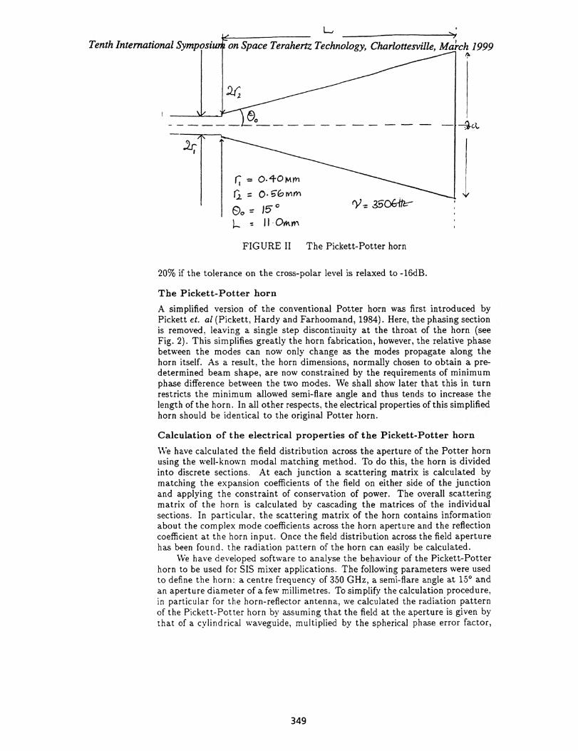
FIGURE II The Pickett-Potter horn
20% if the tolerance on the cross-polar level is relaxed to -16dB.
The Pickett-Potter horn
A simplified version of the conventional Potter horn was first introduced byPickett et. a/ (Pickett, Hardy and Farhoomand, 1984). Here, the phasing sectionis removed, leaving a single step discontinuity at the throat of the horn (seeFig. 2). This simplifies greatly the horn fabrication, however, the relative phasebetween the modes can now only change as the modes propagate along thehorn itself. As a result, the horn dimensions, normally chosen to obtain a pre-determined beam shape, are now constrained by the requirements of minimumphase difference between the two modes. We shall show later that this in turnrestricts the minimum allowed semi-flare angle and thus tends to increase thelength of the horn. In all other respects, the electrical properties of this simplifiedhorn should be identical to the original Potter horn.
Calculation of the electrical properties of the Pickett-Potter horn
We have calculated the field distribution across the aperture of the Potter hornusing the well-known modal matching method. To do this, the horn is dividedinto discrete sections. At each junction a scattering matrix is calculated bymatching the expansion coefficients of the field on either side of the junctionand applying the constraint of conservation of power. The overall scatteringmatrix of the horn is calculated by cascading the matrices of the individualsections. In particular, the scattering matrix of the horn contains information.about the complex mode coefficients across the horn aperture and the reflectioncoefficient at the horn input. Once the field distribution across the field aperturehas been found. the radiation pattern of the horn can easily be calculated.
We have developed software to analyse the behaviour of the Pickett-Potterhorn to be used for SIS mixer applications. The following parameters were usedto define the horn: a centre frequency of 350 GHz, a semi-flare angle at 15° andan aperture diameter of a few millimetres. To simplify the calculation procedure,in particular for the horn-reflector antenna, we calculated the radiation patternof the Pickett-Potter horn by assuming that the field at the aperture is given bythat of a cylindrical waveguide, multiplied by the spherical phase error factor,
349

Tenth International Symposium on Space Terahertz Technology, Charlottesville, March 1999
kr2exp • where r is the radial distance in the horn aperture. k is the free space2Lwavenumber and L is the horn length. The phase difference between the twomodes as they propagate along the horn is given by
Ac5 = dz dz (1)
J AgTE(Z) AgrAi(Z)
where z is axial distance along the horn. We have used this method in thepast to calculate the radiation pattern of a corrugated horns and have obtainedagreement between the computed and measured results down to -40 dB. UsingKirchhoff's aperture diffraction theory to calculate the radiated far fields weobtain:
_ jk exp –jkR (1 +
3 cos() rE = )[fx cos o + .f . sin 0]
47rR k3
E0 = jk exp –jkR
(cos° + --)[fs sin o – f, cos o]47rR k
where R,0 and are the spherical coordinates of the plane of observation, 0 isthe guided propagation constant and fx,y are the far field components of theEas,y aperture field components and can be written as:
f f2 f a
Ea (r', 01 ) exp [j kr' sin cos (0 – 1 ) -jr' dr' del (4)
The co-polar and cross-polar patterns can then be written using Ludwig's thirddefinition of cross polarisation as:
Ecp ( sin9 cos Ea,
(5)Exp cos° – sin Ec5
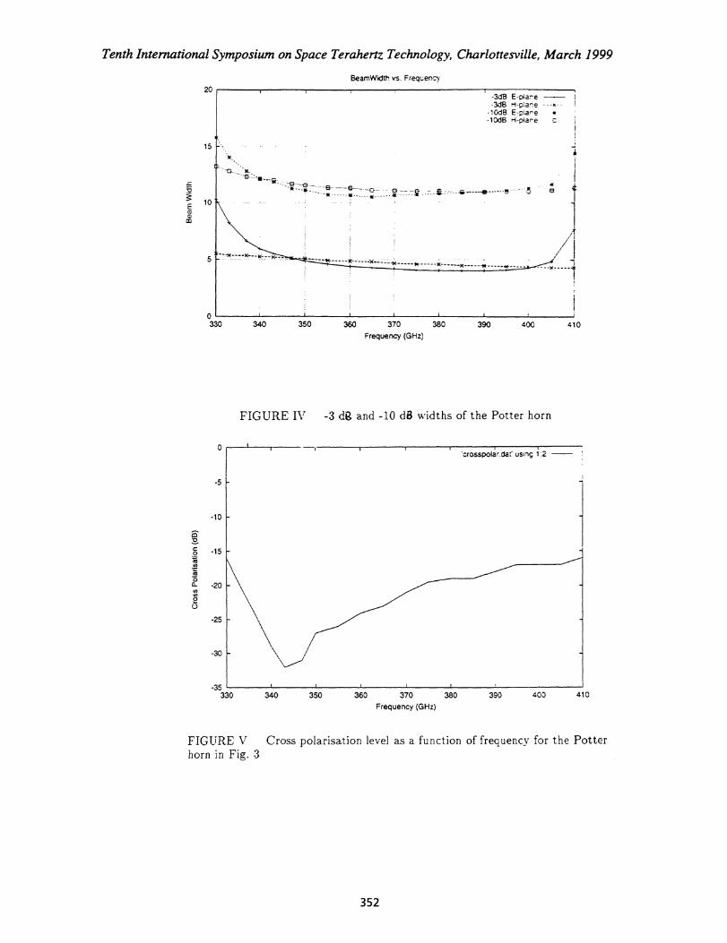
An example of these calculations is shown in Fig. 3 where we have computedthe radiation pattern at three frequencies. Note that the pattern quality at theoptimum frequency (350 GHz) is comparable to that of a corrugated horn. By380 GHz, however, the cross-polarisation level has already increased to -15 dB.A plot of the -3 dB and -10 dB beamwidths of the Pickett-Potter horn as afunction of frequency is shown in Fig. 4. The best indicator of the bandwidth ofthe Pickett-Potter horn is the cross-polarisation level,(the sidelobe level is lowover a very wide band). We have therefore plotted the cross-polar level as afunction of frequency in Fig. 5, where the horn dimensions have been chosento match those used in Fig. 3. We see that, over this frequency range, thecross polarisation level is comparable to that of a corrugated horn of similardimensions and, unsurprisingly, much better than that of a diagonal horn overmuch of the frequency band of comparison.
A very useful design tool is the plot of the relative beamwidth of the horn) as a function of the phase error parameter A which defined as
a 0c,A = –
A tan —
2 (6)
An example design curve, which was computed for a fixed semiflare angle of 15°is given in Fig. 6.
(2)
(3)
CI 0
350

T'picket_beam_350.dat using 1:2 -'pecket_beam_350.dat' using 1:3 - - - ipicket_beam_350.dar using 1:5
10 20 30 40 50Angle
60 70 80 90
i10 20 30 40 50
Angie
'picket_beam_380.dar using 1:2ipickel_beam_38040 using 1:3ipicket_beam_380.dat' using 1:5
■.■■■••
'picket beam_330.dar using_12 -Tenth Ints Symposium on Space Teraherle irrf rtotte,ville, March 1999p e _beam_ .•
FIGURE 111 Pickett potter horn radiation patterns over the frequency range330-380 GHz for a horn with semi flare angle of 15° and length 11.6 mm . (a)330 Gilz (b) 350 GHz (c) 380 Gliz.
351
Tenth International Symposium on Space Terahertz Technology, Charlottesville, March 1999
BearnWidth vs. Frequency
20-3,18 E-otare-3d8 H .-plane - -- x - -
-10418 E -pier e-10d8 H are
15
•-- - * ------ ------ 4!'
330 340 350 360 370 380 390 400 410
Frequency (GHz)
FIGURE IV -3 da and -10 d8 widths of the Potter horn
'crosspolal r.ciat' using
-10
-25
-30
340 350 360 370 380 390 403 410
Frequency (GHz)
FIGURE V Cross polarisation level as a function of frequency for the Potterhorn in Fig. 3
-35 330
352

Tenth International Symposium on Space Terahertz Technology, Charlottesville, March 1999
1.3
'beamwidth_vs_delta.dar using 1:2 -
C.90
0.7
0.8
0.9
1.1
1.2
0.6 0.2 0.3 0.4 0.5 0.6 0.7 0.8 0.9
ekt.$e 'Error bos'o
0.6
0.55
0.5
0.45cC
0.4
0.35
0.30.2 0.3 0.4 0.5 0.6 0.7 0.8 0.9
Phase Error
FIGURE VI A plot of the beamwidth of the Pickett-Potter horn as a functionof the phase error. .:1, as defined by eqn. 6. The semi-flare angle of the hornwas fixed at 15°
353
Tenth International Symposium on Space Terahertz Technology, Charlottesville, March 1999
It should be noted that at each point on the plot the dimensions of thestep were adjusted (by varying r 1 . r2 ) to give optimum performance t minimumcross-polarisation). It is interesting to note that the plot has a minimum whichcorresponds to the minimum beamwidth for a given horn semi-flare an gle. Asimilar minimum occurs for corrugated horns. where the horn design becomes"optimum" in the sense of having maximum gain. Less encouragin g was thediscovery that the dynamic design range is severely compromised by the ab-sence of the phasing section. This is why the phase error parameter cannot beincreased to the values obtained by corrugated horns. In spite of this. it can beseen from Fig. 6 that a Pickett-Potter horn that is not diffraction-limited canstill be realised using a moderately small flare angle.
THE POTTER HORN-REFLECTOR ANTENNA
Beams shape
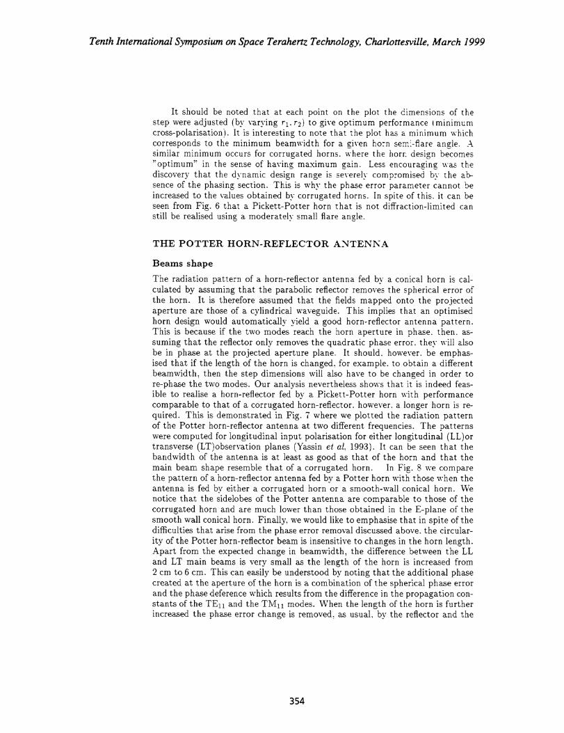
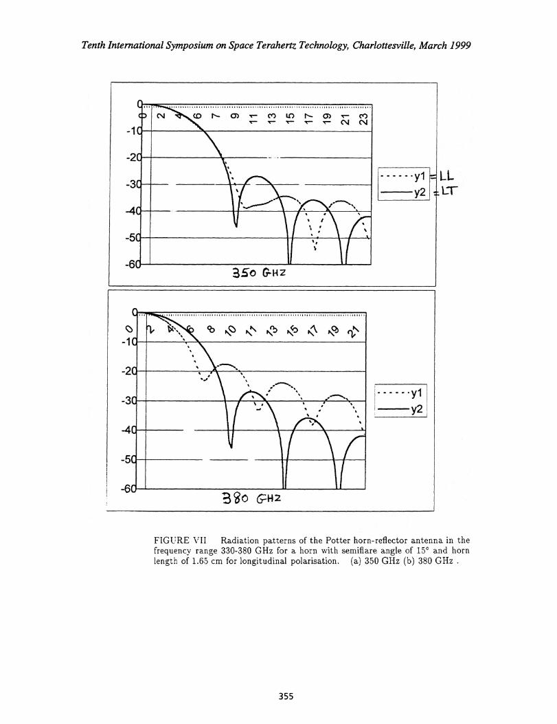
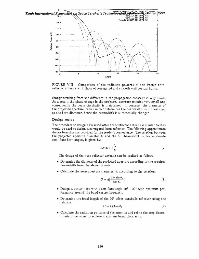
The radiation pattern of a horn-reflector antenna fed by a conical horn is cal-culated by assuming that the parabolic reflector removes the spherical error ofthe horn. It is therefore assumed that the fields mapped onto the projectedaperture are those of a cylindrical waveguide. This implies that an optimisedhorn design would automatically yield a good horn-reflector antenna pattern.This is because if the two modes reach the horn aperture in phase. then. as-suming that the reflector only removes the quadratic phase error. they will alsobe in phase at the projected aperture plane. It should. however. be emphas-ised that if the length of the horn is changed, for example. to obtain a differentbeamwidth, then the step dimensions will also have to be changed in order tore-phase the two modes. Our analysis nevertheless shows that it is indeed feas-ible to realise a horn-reflector fed by a Pickett-Potter horn with performancecomparable to that of a corrugated horn-reflector, however. a longer horn is re-quired. This is demonstrated in Fig. 7 where we plotted the radiation patternof the Potter horn-reflector antenna at two different frequencies. The patternswere computed for longitudinal input polarisation for either longitudinal (LL)ortransverse (LT)observation planes (Yassin et al. 1993). It can be seen that thebandwidth of the antenna is at least as good as that of the horn and that themain beam shape resemble that of a corrugated horn. In Fig . 8 we comparethe pattern of a horn-reflector antenna fed by a Potter horn with those when theantenna is fed by either a corrugated horn or a smooth-wall conical horn. Wenotice that the sidelobes of the Potter antenna are comparable to those of thecorrugated horn and are much lower than those obtained in the &plane of thesmooth wall conical horn. Finally. we would like to emphasise that in spite of thedifficulties that arise from the phase error removal discussed above. the circular-ity of the Potter horn-reflector beam is insensitive to changes in the horn length.Apart from the expected change in beamwidth, the difference between the LLand LT main beams is very small as the length of the horn is increased from2 cm to 6 cm. This can easily be understood by noting that the additional phasecreated at the aperture of the horn is a combination of the spherical phase errorand the phase deference which results from the difference in the propagation con-stants of the TE ii and the TM ii modes. When the length of the horn is furtherincreased the phase error change is removed, as usual, by the reflector and the
354
D
,
c\I . (D N. 0) v— co L() N . 0) 1-- Ct)..r.- 1-- T-- ‘..—• N.-- (NI (NJ
.a
ri . .. ......_,
I . . ; .. ...,,350
-1
-2
-3
-4
-5
-6
yl t.-
}12
0 H2
ri, tk• • cb.ti, 0 N.N N N.n) N(f
,) *. NNC:b eie
.• .. ,.„„, .. .,...,,,. .,, .. . . ...... .
• .i ., ..
I y
-1C
-2
-3
-4
-5
-6
.....yi
y2
Tenth International Symposium on Space Terahertz Technology, Charlottesville, March 1999
LLLT
FIGURE VII Radiation patterns of the Potter horn-reflector antenna in thefrequency range 330-380 GHz for a horn with semiflare angle of 15° and hornlength of 1.65 cm for longitudinal polarisation. (a) 350 GHz (b) 380 GHz .
355
5 10 15 20 25
Space Terahertz Techna loect°f- ,iikiarch J999_.cfiat•
'corru L.T.clar using 1:2 - -'coru:LL.cie using 1:2
lrixide_sinooth.cle us:ng 12 - - - -
Tenth International Symposiii-5 -
Angle
FIGURE VIII Comparison of the radiation patterns of the Potter horn-reflector antenna with those of corrugated and smooth wall conical horns.
change resulting from the difference in the propagation constant is very small.As a result, the phase change in the projected aperture remains very small andconsequently the beam circularity is maintained. In contrast. the diameter ofthe projected aperture. which in fact determines the beamwidth. is proportionalto the horn diameter, hence the beamwidth is substantially changed.
Design recipe
The procedure to design a Pickett-Potter horn-reflector antenna is similar to thatwould be used to design a corrugated horn-reflector. The following approximatedesign formulas are provided for the reader's convenience. The relation betweenthe projected aperture diameter D and the full beamwidth is, for moderatesemi-flare horn angles, is given by:
AAO 1.2—
D
The design of the horn reflector antenna can be realised as follows:
• Determine the diameter of the projected aperture according to the requiredbeamwidth from the above formula
• Calculate the horn aperture diameter, d, according to the relation:
D = d[ 1 + sin Oo
cos 0,,
• Design a potter horn with a semiflare angle 10 0 – 20 0 with optimum per-formance around the band centre frequency.
• Determine the focal length of the 900 offset parabolic reflector using the
relationD 4f tan 00 (9)
• Calculate the radiation patterns of the antenna and refine the step discon-tinuity dimensions to achieve maximum beam circularity.
(7)
(8)
356
Tenth International Symposium on Space Terahertz Technology, Charlottesville, March 1999
CONCLUSION
We have shown that the Pickett-Potter horn can be employed in conjunctionwith horn-reflector antennas, provided that the TEn and TM ii modes reachthe projected aperture in phase. Although the absence of a phasing section inthe Picket-Potter version restricts the horn design flexibility, our study showedthat practical horn-reflector antenna dimensions suitable for submillimetre-wavearray receivers can still be found. The bandwidth of the antenna is clearlydependent on the specified cross- polarisation level. For example, a -20 dbcross-polar level can be maintained over a fractional bandwidth of 10%, while-15 db level can be achieved over a fractional bandwidth of 25 %.
REFERENCES
Withington. S.. Yassin, G., Buffey. M. and Norden, C. (1997): "A Horn-Reflectorantenna for high performance submillimetre imaging arrays," Int'l J. IRand MM Waves. vol. 18, no. 2, pp. 341-358, 1997.
Potter, P. D. "A new horn antenna with suppressed sidelobes and equal beam-widths. - Microwave J., 6 pp. 71-78, 1963. finline mixer for astronomicalimaging arrays ." Elctron. Lett. Vol. 33, PP. 498-500, 1997.
Pickett, H. M., Hardy, J. C. and Farhoomand, J., "Characterisation of a dual-mode horn for submillimetre wavelengths," IEEE Trans. Microwave The-ory Tech. MTT-32, no. 8, pp. 936-937, 1984.
Silver. S. Microwave antenna theory and Design. McGraw-Hill Book Co., Inc.,New York, 1949. pp. 162.
Yassin. G.. Robson. M. and Duffett-Smith. P. J. "The electrical characteristicsof a conical horn-reflector antenna employing a corrugated horn", IEEEAntennas and propagation, vol. AP-41, pp. 357-361, April 1993.
357