the x86 microprocessor - shankarrajagopal.github.io · evolution from 8086 to 8088 • the 8086...
TRANSCRIPT

The x86 PCAssembly Language, Design, and InterfacingBy Muhammad Ali Mazidi, Janice Gillespie Mazidi and Danny Causey
© 2010, 2003, 2000, 1998 Pearson Higher Education, Inc.Pearson Prentice Hall - Upper Saddle River, NJ 07458
ORG ; ONEDec Hex Bin1 1 00000001
The x86Microprocessor
The x86 PCAssembly Language, Design, and InterfacingBy Muhammad Ali Mazidi, Janice Gillespie Mazidi and Danny Causey
© 2010, 2003, 2000, 1998 Pearson Higher Education, Inc.Pearson Prentice Hall - Upper Saddle River, NJ 07458
OBJECTIVESthis chapter enables the student to:
• Describe the Intel family of microprocessors from 8085 to Pentium®.– In terms of bus size, physical memory & special features.
• Explain the function of the EU (execution unit) and BIU (bus interface unit).
• Describe pipelining and how it enables the CPUto work faster.
• List the registers of the 8086.• Code simple MOV and ADD instructions.
– Describe the effect of these instructions on their operands.

The x86 PCAssembly Language, Design, and InterfacingBy Muhammad Ali Mazidi, Janice Gillespie Mazidi and Danny Causey
© 2010, 2003, 2000, 1998 Pearson Higher Education, Inc.Pearson Prentice Hall - Upper Saddle River, NJ 07458
OBJECTIVESthis chapter enables the student to:
• State the purpose of the code segment,data segment,stack segment, and extra segment.
• Explain the difference between a logical address and a physical address.
• Describe the "little endian" storage conventionof x86 microprocessors.
• State the purpose of the stack.• Explain the function of PUSH and POP instructions.• List the bits of the flag register and briefly state the
purpose of each bit.
(cont)
The x86 PCAssembly Language, Design, and InterfacingBy Muhammad Ali Mazidi, Janice Gillespie Mazidi and Danny Causey
© 2010, 2003, 2000, 1998 Pearson Higher Education, Inc.Pearson Prentice Hall - Upper Saddle River, NJ 07458
OBJECTIVESthis chapter enables the student to:
• Demonstrate the effect of ADD instructions onthe flag register.
• List the addressing modes of the 8086 and recognize examples of each mode.
• Know how to use flowcharts and pseudocode in program development.
(cont)
The x86 PCAssembly Language, Design, and InterfacingBy Muhammad Ali Mazidi, Janice Gillespie Mazidi and Danny Causey
© 2010, 2003, 2000, 1998 Pearson Higher Education, Inc.Pearson Prentice Hall - Upper Saddle River, NJ 07458
1.1 BRIEF HISTORY OF THE x86 FAMILY evolution from 8080/8085 to 8086
• In 1978, Intel Corporation introduced the 16-bit 8086 microprocessor, a major improvement over the previous generation 8080/8085 series.– The 8086 capacity of 1 megabyte of memory exceeded
the 8080/8085 maximum of 64K bytes of memory.– 8080/8085 was an 8-bit system, which could work on
only 8 bits of data at a time.• Data larger than 8 bits had to be broken into 8-bit pieces
to be processed by the CPU.– 8086 was a pipelined processor, as opposed to the
nonpipelined 8080/8085.

The x86 PCAssembly Language, Design, and InterfacingBy Muhammad Ali Mazidi, Janice Gillespie Mazidi and Danny Causey
© 2010, 2003, 2000, 1998 Pearson Higher Education, Inc.Pearson Prentice Hall - Upper Saddle River, NJ 07458
1.1 BRIEF HISTORY OF THE x86 FAMILY evolution from 8080/8085 to 8086
The x86 PCAssembly Language, Design, and InterfacingBy Muhammad Ali Mazidi, Janice Gillespie Mazidi and Danny Causey
© 2010, 2003, 2000, 1998 Pearson Higher Education, Inc.Pearson Prentice Hall - Upper Saddle River, NJ 07458
1.1 BRIEF HISTORY OF THE x86 FAMILY evolution from 8086 to 8088
• The 8086 microprocessor has a 16-bit data bus, internally and externally.– All registers are 16 bits wide, and there is a 16-bit
data bus to transfer data in and out of the CPU• There was resistance to a 16-bit external bus as
peripherals were designed around 8-bit processors.• A printed circuit board with a 16-bit data also bus cost more.
• As a result, Intel came out with the 8088 version.– Identical to the 8086, but with an 8-bit data bus.
• Picked up by IBM as the microprocessor in designing the PC.
The x86 PCAssembly Language, Design, and InterfacingBy Muhammad Ali Mazidi, Janice Gillespie Mazidi and Danny Causey
© 2010, 2003, 2000, 1998 Pearson Higher Education, Inc.Pearson Prentice Hall - Upper Saddle River, NJ 07458
1.1 BRIEF HISTORY OF THE x86 FAMILY success of the 8088
• The 8088-based IBM PC was an great success, because IBM & Microsoft made it an open system.– Documentation and specifications of the hardware
and software of the PC were made public• Making it possible for many vendors to clone the hardware
successfully & spawn a major growth in both hardware and software designs based on the IBM PC.

The x86 PCAssembly Language, Design, and InterfacingBy Muhammad Ali Mazidi, Janice Gillespie Mazidi and Danny Causey
© 2010, 2003, 2000, 1998 Pearson Higher Education, Inc.Pearson Prentice Hall - Upper Saddle River, NJ 07458
1.1 BRIEF HISTORY OF THE x86 FAMILY 80286, 80386, and 80486
• Intel introduced the 80286 in 1982, which IBM picked up for the design of the PC AT.– 16-bit internal & external data buses.– 24 address lines, for 16mb memory. (224 = 16mb)– Virtual memory.
• 80286 can operate in one of two modes:– Real mode - a faster 8088/8086 with the same maximum
of 1 megabyte of memory.– Protected mode - which allows for 16M of memory.
• Also capable of protecting the operating system & programs from accidental or deliberate destruction by a user.
The x86 PCAssembly Language, Design, and InterfacingBy Muhammad Ali Mazidi, Janice Gillespie Mazidi and Danny Causey
© 2010, 2003, 2000, 1998 Pearson Higher Education, Inc.Pearson Prentice Hall - Upper Saddle River, NJ 0745810
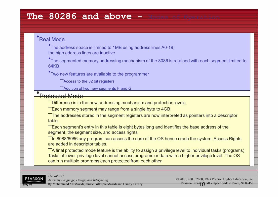
The 80286 and above - Modes of Operation
•Protected Mode–Difference is in the new addressing mechanism and protection levels–Each memory segment may range from a single byte to 4GB–The addresses stored in the segment registers are now interpreted as pointers into a descriptor table–Each segment’s entry in this table is eight bytes long and identifies the base address of the segment, the segment size, and access rights–In 8088/8086 any program can access the core of the OS hence crash the system. Access Rights are added in descriptor tables.–A final protected mode feature is the ability to assign a privilege level to individual tasks (programs). Tasks of lower privilege level cannot access programs or data with a higher privilege level. The OS can run multiple programs each protected from each other.
•Real Mode•The address space is limited to 1MB using address lines A0-19; the high address lines are inactive•The segmented memory addressing mechanism of the 8086 is retained with each segment limited to 64KB•Two new features are available to the programmer
–Access to the 32 bit registers–Addition of two new segments F and G
Brey 59
The x86 PCAssembly Language, Design, and InterfacingBy Muhammad Ali Mazidi, Janice Gillespie Mazidi and Danny Causey
© 2010, 2003, 2000, 1998 Pearson Higher Education, Inc.Pearson Prentice Hall - Upper Saddle River, NJ 0745811
Virtual 8086 Mode
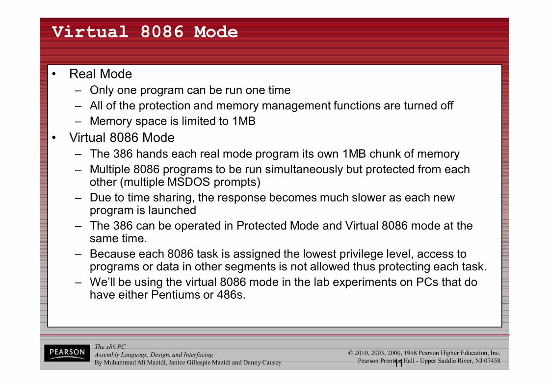
• Real Mode– Only one program can be run one time– All of the protection and memory management functions are turned off– Memory space is limited to 1MB
• Virtual 8086 Mode– The 386 hands each real mode program its own 1MB chunk of memory– Multiple 8086 programs to be run simultaneously but protected from each
other (multiple MSDOS prompts)– Due to time sharing, the response becomes much slower as each new
program is launched– The 386 can be operated in Protected Mode and Virtual 8086 mode at the
same time.– Because each 8086 task is assigned the lowest privilege level, access to
programs or data in other segments is not allowed thus protecting each task.– We’ll be using the virtual 8086 mode in the lab experiments on PCs that do
have either Pentiums or 486s.
The x86 PCAssembly Language, Design, and InterfacingBy Muhammad Ali Mazidi, Janice Gillespie Mazidi and Danny Causey
© 2010, 2003, 2000, 1998 Pearson Higher Education, Inc.Pearson Prentice Hall - Upper Saddle River, NJ 07458
1.1 BRIEF HISTORY OF THE x86 FAMILY 80286, 80386, and 80486
• Virtual memory is a way of fooling the processor into thinking it has access to an almost unlimited amount of memory.– By swapping data between disk storage and RAM.
The x86 PCAssembly Language, Design, and InterfacingBy Muhammad Ali Mazidi, Janice Gillespie Mazidi and Danny Causey
© 2010, 2003, 2000, 1998 Pearson Higher Education, Inc.Pearson Prentice Hall - Upper Saddle River, NJ 0745813
Virtual Memory
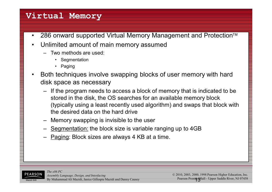
• 286 onward supported Virtual Memory Management and Protection• Unlimited amount of main memory assumed
– Two methods are used:• Segmentation• Paging
• Both techniques involve swapping blocks of user memory with hard disk space as necessary– If the program needs to access a block of memory that is indicated to be
stored in the disk, the OS searches for an available memory block (typically using a least recently used algorithm) and swaps that block with the desired data on the hard drive
– Memory swapping is invisible to the user– Segmentation: the block size is variable ranging up to 4GB– Paging: Block sizes are always 4 KB at a time.
Mazidi 648
The x86 PCAssembly Language, Design, and InterfacingBy Muhammad Ali Mazidi, Janice Gillespie Mazidi and Danny Causey
© 2010, 2003, 2000, 1998 Pearson Higher Education, Inc.Pearson Prentice Hall - Upper Saddle River, NJ 0745814
Memory Map of a PC
Conventional memory
Upper memory block
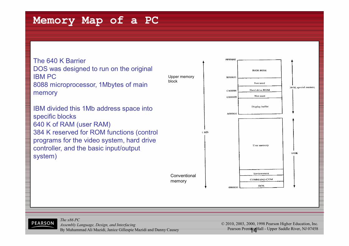
The 640 K BarrierDOS was designed to run on the original IBM PC8088 microprocessor, 1Mbytes of main memory
IBM divided this 1Mb address space into specific blocks640 K of RAM (user RAM)384 K reserved for ROM functions (control programs for the video system, hard drive controller, and the basic input/output system)

The x86 PCAssembly Language, Design, and InterfacingBy Muhammad Ali Mazidi, Janice Gillespie Mazidi and Danny Causey
© 2010, 2003, 2000, 1998 Pearson Higher Education, Inc.Pearson Prentice Hall - Upper Saddle River, NJ 07458
1.1 BRIEF HISTORY OF THE x86 FAMILY 80286, 80386, and 80486
• In 1985 Intel introduced 80386 (or 80386DX).– 32-bit internally/externally, with a 32-bit address bus.– Capable of handling memory of up to 4 gigabytes. (232)– Virtual memory increased to 64 terabytes. (246)
• Later Intel introduced 386SX, internally identical, but with a 16-bit external data bus & 24-bit address bus.– This makes the 386SX system much cheaper.
• Since general-purpose processors could not handle mathematical calculations rapidly, Intel introduced numeric data processing chips.– Math coprocessors, such as 8087, 80287, 80387.
The x86 PCAssembly Language, Design, and InterfacingBy Muhammad Ali Mazidi, Janice Gillespie Mazidi and Danny Causey
© 2010, 2003, 2000, 1998 Pearson Higher Education, Inc.Pearson Prentice Hall - Upper Saddle River, NJ 07458
1.1 BRIEF HISTORY OF THE x86 FAMILY 80286, 80386, and 80486
• On the 80486, in 1989, Intel put a greatly enhanced 80386 & math coprocessor on a single chip.– Plus additional features such as cache memory.
• Cache memory is static RAM with a very fast access time.
• All programs written for the 8088/86 will run on286, 386, and 486 computers.
The x86 PCAssembly Language, Design, and InterfacingBy Muhammad Ali Mazidi, Janice Gillespie Mazidi and Danny Causey
© 2010, 2003, 2000, 1998 Pearson Higher Education, Inc.Pearson Prentice Hall - Upper Saddle River, NJ 07458
1.1 BRIEF HISTORY OF THE x86 FAMILY 80286, 80386, and 80486

The x86 PCAssembly Language, Design, and InterfacingBy Muhammad Ali Mazidi, Janice Gillespie Mazidi and Danny Causey
© 2010, 2003, 2000, 1998 Pearson Higher Education, Inc.Pearson Prentice Hall - Upper Saddle River, NJ 07458
1.1 BRIEF HISTORY OF THE x86 FAMILY Pentium® & Pentium® Pro
• In 1992, Intel released the Pentium®. (not 80586)– A name can be copyrighted, but numbers cannot.
• On release, Pentium® had speeds of 60 & 66 MHz.– Designers utilized over 3 million transistors on the
Pentium® chip using submicron fabrication technology.– New design features made speed twice that of 80486/66.
• Over 300 times faster than that of the original 8088.
• Pentium® is fully compatible with previous x86 processors but includes several new features.– Separate 8K cache memory for code and data.– 64-bit bus, and a vastly improved floating-point processor.
The x86 PCAssembly Language, Design, and InterfacingBy Muhammad Ali Mazidi, Janice Gillespie Mazidi and Danny Causey
© 2010, 2003, 2000, 1998 Pearson Higher Education, Inc.Pearson Prentice Hall - Upper Saddle River, NJ 07458
1.1 BRIEF HISTORY OF THE x86 FAMILY Pentium® & Pentium® Pro
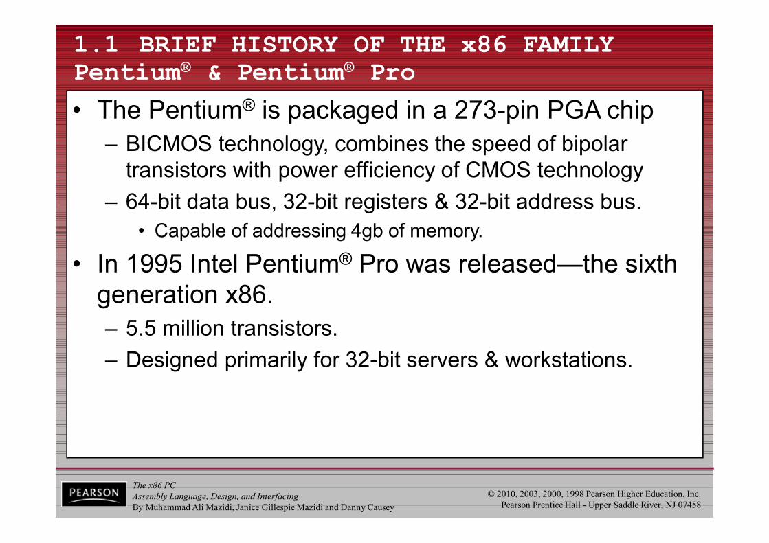
• The Pentium® is packaged in a 273-pin PGA chip– BICMOS technology, combines the speed of bipolar
transistors with power efficiency of CMOS technology– 64-bit data bus, 32-bit registers & 32-bit address bus.
• Capable of addressing 4gb of memory.
• In 1995 Intel Pentium® Pro was released—the sixth generation x86.– 5.5 million transistors.– Designed primarily for 32-bit servers & workstations.
The x86 PCAssembly Language, Design, and InterfacingBy Muhammad Ali Mazidi, Janice Gillespie Mazidi and Danny Causey
© 2010, 2003, 2000, 1998 Pearson Higher Education, Inc.Pearson Prentice Hall - Upper Saddle River, NJ 07458
1.1 BRIEF HISTORY OF THE x86 FAMILY Pentium® & Pentium® Pro

The x86 PCAssembly Language, Design, and InterfacingBy Muhammad Ali Mazidi, Janice Gillespie Mazidi and Danny Causey
© 2010, 2003, 2000, 1998 Pearson Higher Education, Inc.Pearson Prentice Hall - Upper Saddle River, NJ 07458
1.1 BRIEF HISTORY OF THE x86 FAMILY Pentium® II
• In 1997 Intel introduced the Pentium® II processor– 7.5-million-transistor processor featured MMX
(MultiMedia Extension) technology incorporatedinto the CPU.
• For fast graphics and audio processing.
• In 1998 the Pentium® II Xeon was released.– Primary market is for servers and workstations.
• In 1999, Celeron® was released.– Lower cost & good performance make it ideal for PCs
used to meet educational and home business needs.
The x86 PCAssembly Language, Design, and InterfacingBy Muhammad Ali Mazidi, Janice Gillespie Mazidi and Danny Causey
© 2010, 2003, 2000, 1998 Pearson Higher Education, Inc.Pearson Prentice Hall - Upper Saddle River, NJ 07458
1.1 BRIEF HISTORY OF THE x86 FAMILY Pentium® III
• In 1999 Intel released Pentium® III.– 9.5-million-transistor processor.– 70 new instructions called SIMD.
• Enhance video/audio performance in 3-D imaging, and streaming audio.
• In 1999 Intel introduced the Pentium® III Xeon.– Designed more for servers and business workstations
with multiprocessor configurations.
The x86 PCAssembly Language, Design, and InterfacingBy Muhammad Ali Mazidi, Janice Gillespie Mazidi and Danny Causey
© 2010, 2003, 2000, 1998 Pearson Higher Education, Inc.Pearson Prentice Hall - Upper Saddle River, NJ 07458
1.1 BRIEF HISTORY OF THE x86 FAMILY Pentium® 4
• The Pentium® 4 debuted late in 1999.– Speeds of 1.4 to 1.5 GHz.– System bus operates at 400 MHz
• Completely new 32-bit architecture, called NetBurst.– Designed for heavy multimedia processing.
• Video, music, and graphic file manipulation on the Internet.– New cache and pipelining technology & expansion of
the multimedia instruction set make the P4 a high-end media processing microprocessor.
The x86 PCAssembly Language, Design, and InterfacingBy Muhammad Ali Mazidi, Janice Gillespie Mazidi and Danny Causey
© 2010, 2003, 2000, 1998 Pearson Higher Education, Inc.Pearson Prentice Hall - Upper Saddle River, NJ 07458
1.1 BRIEF HISTORY OF THE x86 FAMILY Intel 64 Architecture
• Intel has selected Itanium® as the new brand name for the first product in its 64-bit family of processors.– Formerly called Merced.
• The evolution of microprocessors is increasingly influenced by the evolution of the Internet.– Itanium® architecture is designed to meet Internet-driven
needs for servers & high-performance workstations.– Itanium® will have the ability to execute many instructions
simultaneously, plus extremely large memory capabilities.
The x86 PCAssembly Language, Design, and InterfacingBy Muhammad Ali Mazidi, Janice Gillespie Mazidi and Danny Causey
© 2010, 2003, 2000, 1998 Pearson Higher Education, Inc.Pearson Prentice Hall - Upper Saddle River, NJ 07458
1.2 INSIDE THE 8088/86
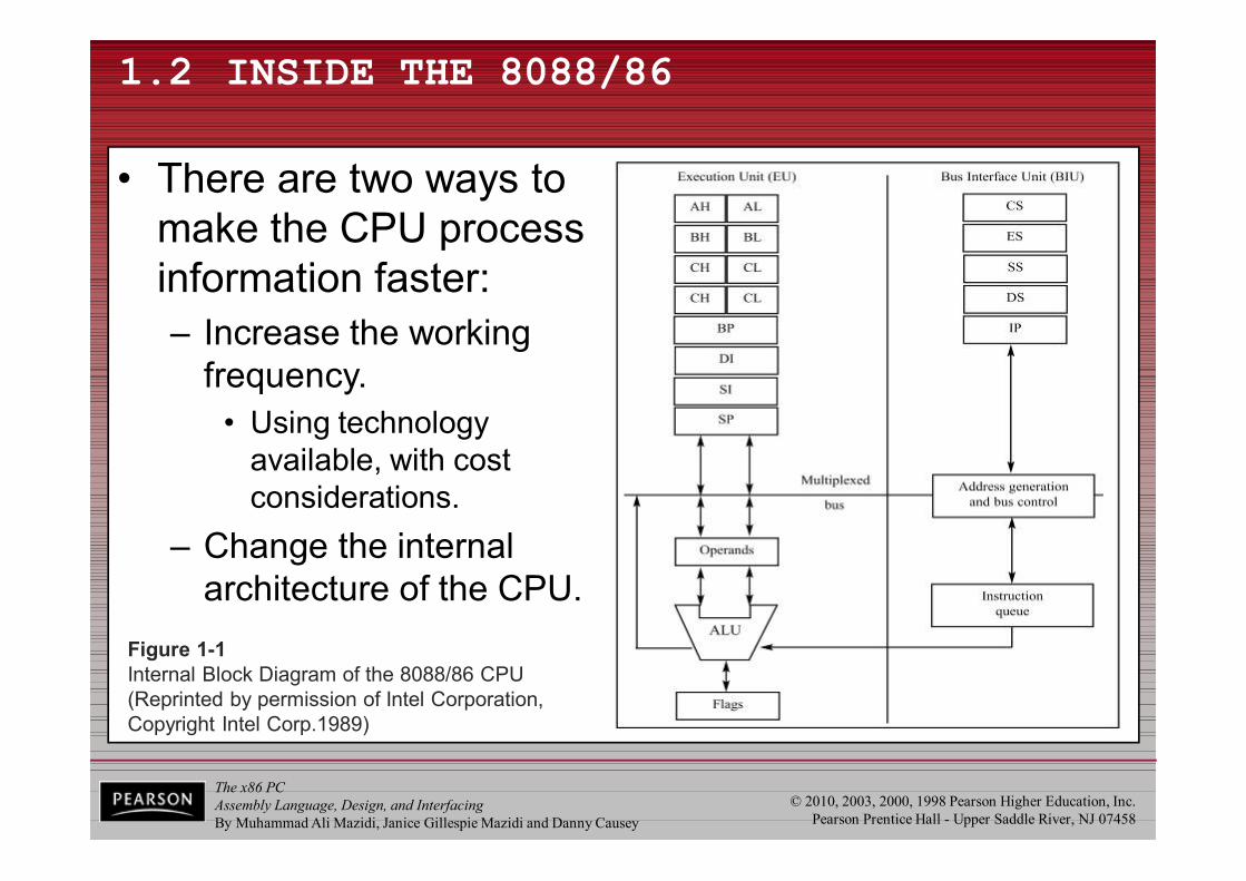
Figure 1-1Internal Block Diagram of the 8088/86 CPU(Reprinted by permission of Intel Corporation,Copyright Intel Corp.1989)
• There are two ways tomake the CPU processinformation faster:– Increase the working
frequency.• Using technology
available, with cost considerations.
– Change the internalarchitecture of the CPU.

The x86 PCAssembly Language, Design, and InterfacingBy Muhammad Ali Mazidi, Janice Gillespie Mazidi and Danny Causey
© 2010, 2003, 2000, 1998 Pearson Higher Education, Inc.Pearson Prentice Hall - Upper Saddle River, NJ 07458
1.2 INSIDE THE 8088/86 pipelining
• 8085 could fetch or execute at any given time.– The idea of pipelining in its simplest form is to allow the
CPU to fetch and execute at the same time.
Figure 1-2 Pipelined vs Nonpipelined Execution
The x86 PCAssembly Language, Design, and InterfacingBy Muhammad Ali Mazidi, Janice Gillespie Mazidi and Danny Causey
© 2010, 2003, 2000, 1998 Pearson Higher Education, Inc.Pearson Prentice Hall - Upper Saddle River, NJ 0745827
Execution and Bus Interface Units

The x86 PCAssembly Language, Design, and InterfacingBy Muhammad Ali Mazidi, Janice Gillespie Mazidi and Danny Causey
© 2010, 2003, 2000, 1998 Pearson Higher Education, Inc.Pearson Prentice Hall - Upper Saddle River, NJ 0745828
Fetch and Execute Cycle
• Fetch and execute cycles overlap– BIU outputs the contents of the IP onto the address bus– Register IP is incremented by one or more than one for the next
instruction fetch– Once inside the BIU, the instruction is passed to the queue; this
queue is a first-in-first-out register sometimes likened to a pipeline– Assuming that the queue is initially empty the EU immediately draws
this instruction from the queue and begins execution– While the EU is executing this instruction, the BIU proceeds to fetch a
new instruction.• BIU will fill the queue with several new instructions before the EU
is ready to draw its next instruction– The cycle continues with the BIU filling the queue with instructions
and the EU fetching and executing these instructions
The x86 PCAssembly Language, Design, and InterfacingBy Muhammad Ali Mazidi, Janice Gillespie Mazidi and Danny Causey
© 2010, 2003, 2000, 1998 Pearson Higher Education, Inc.Pearson Prentice Hall - Upper Saddle River, NJ 07458
1.2 INSIDE THE 8088/86 pipelining
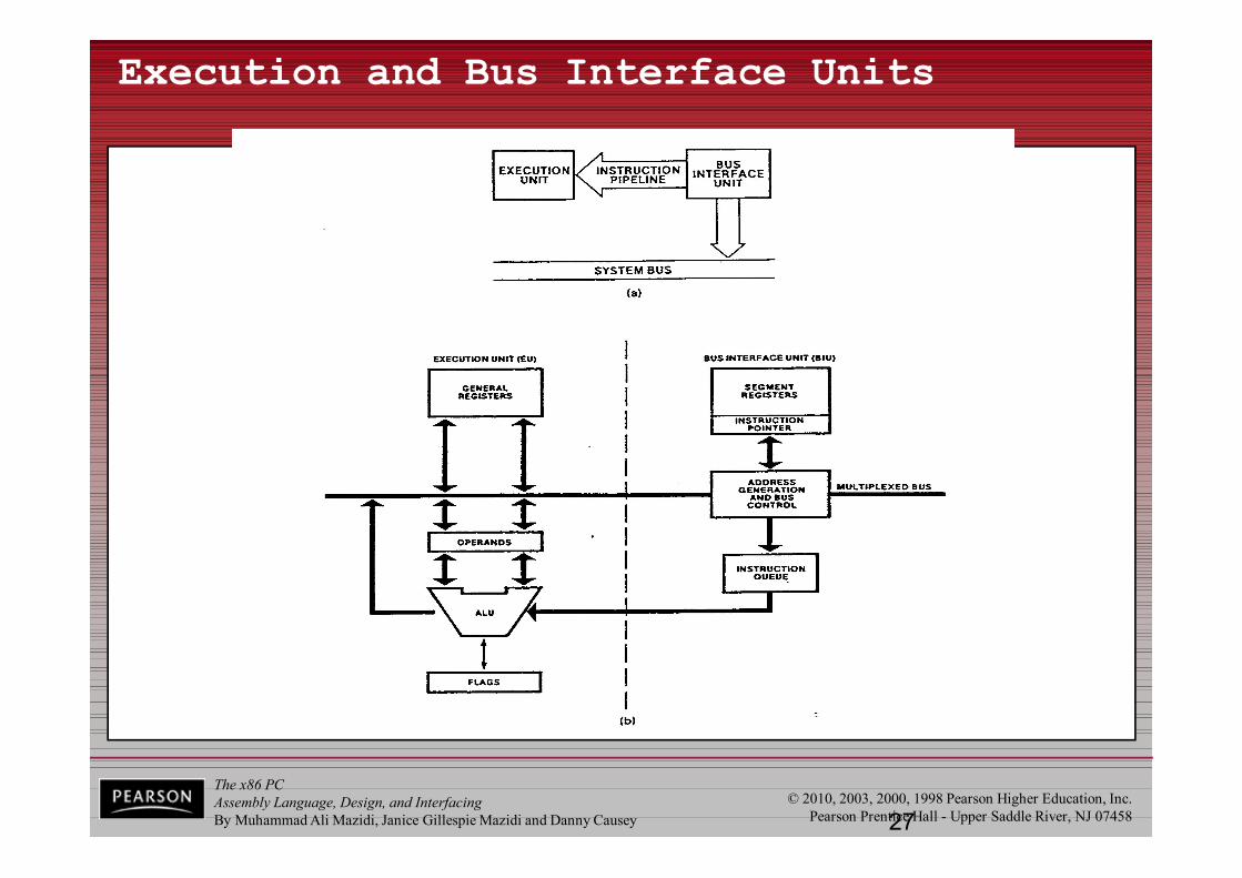
• Intel implemented pipelining in 8088/86 by splitting the internal structure of the into two sections: – The execution unit (EU) and the bus interface unit (BIU).
• These two sections work simultaneously.
• The BIU accesses memory and peripherals, while the EU executes instructions previously fetched.– This works only if the BIU keeps ahead of the EU, so
the BIU of the 8088/86 has a buffer, or queue • The buffer is 4 bytes long in 8088 and 6 bytes in 8086.
• 8088/86 pipelining has two stages, fetch & execute.– In more powerful computers, it can have many stages.
The x86 PCAssembly Language, Design, and InterfacingBy Muhammad Ali Mazidi, Janice Gillespie Mazidi and Danny Causey
© 2010, 2003, 2000, 1998 Pearson Higher Education, Inc.Pearson Prentice Hall - Upper Saddle River, NJ 07458
1.2 INSIDE THE 8088/86 pipelining
• If an instruction takes too long to execute, the queue is filled to capacity and the buses will sit idle
• In some circumstances, the microprocessor must flush out the queue.– When a jump instruction is executed, the BIU starts to
fetch information from the new location in memory and information fetched previously is discarded.
– The EU must wait until the BIU fetches the new instruction
• In computer science terminology, a branch penalty.– In a pipelined CPU, too much jumping around reduces
the efficiency of a program.
The x86 PCAssembly Language, Design, and InterfacingBy Muhammad Ali Mazidi, Janice Gillespie Mazidi and Danny Causey
© 2010, 2003, 2000, 1998 Pearson Higher Education, Inc.Pearson Prentice Hall - Upper Saddle River, NJ 0745831
Pipelined Architecture
• Three conditions that will cause the EU to enter a wait mode– when the instruction requires access to a memory location not in the queue– when the instruction to be executed is a jump instruction; the instruction
queue should be flushed out (known as branch penalty too much jumping around reduces the efficiency of the program)
– during the execution of slow instructions• for example the instruction AAM (ASCII Adjust for Multiplication) requires
83 clock cycles to complete for an 8086• 8086 vs 8088
– BIU data bus width 8 bits for 8088, BIU data bus width 16 bits for 8086– 8088 instruction queue is four bytes instead of six– 8088 is found to be 30% slower than 8086
• WHY– Long instructions provide more time for the BIU to fill the queue

The x86 PCAssembly Language, Design, and InterfacingBy Muhammad Ali Mazidi, Janice Gillespie Mazidi and Danny Causey
© 2010, 2003, 2000, 1998 Pearson Higher Education, Inc.Pearson Prentice Hall - Upper Saddle River, NJ 0745832
Nonpipelined vs pipelined architecture
Fetch Execute FetchFetch ExecuteExecute
Time
BIU
F F F F F F
Wait E E E Er
Er: a request for data not in the queue
Read Data
Wait E E Ej
FdFdFd
Ej: jump instruction occurs
Fd: Discarded
EU
FF
Wait E
Non-pipelined architecture
Pipelined architecture
The x86 PCAssembly Language, Design, and InterfacingBy Muhammad Ali Mazidi, Janice Gillespie Mazidi and Danny Causey
© 2010, 2003, 2000, 1998 Pearson Higher Education, Inc.Pearson Prentice Hall - Upper Saddle River, NJ 07458
1.2 INSIDE THE 8088/86registers
• In the CPU, registers store information temporarily.– One or two bytes of data to be processed.– The address of data.
• General-purpose registers in 8088/86 processors can be accessed as either 16-bit or 8-bit registers– All other registers can be accessed only
as the full 16 bits.• In 8088/86, data types are either 8 or 16 bits
– To access 12-bit data, for example, a 16-bit registermust be used with the highest 4 bits set to 0.
The x86 PCAssembly Language, Design, and InterfacingBy Muhammad Ali Mazidi, Janice Gillespie Mazidi and Danny Causey
© 2010, 2003, 2000, 1998 Pearson Higher Education, Inc.Pearson Prentice Hall - Upper Saddle River, NJ 07458
1.2 INSIDE THE 8088/86registers
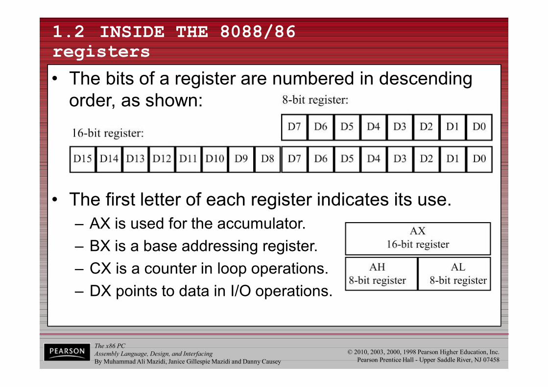
• The bits of a register are numbered in descending order, as shown:
• The first letter of each register indicates its use.– AX is used for the accumulator.– BX is a base addressing register.– CX is a counter in loop operations.– DX points to data in I/O operations.

The x86 PCAssembly Language, Design, and InterfacingBy Muhammad Ali Mazidi, Janice Gillespie Mazidi and Danny Causey
© 2010, 2003, 2000, 1998 Pearson Higher Education, Inc.Pearson Prentice Hall - Upper Saddle River, NJ 0745835
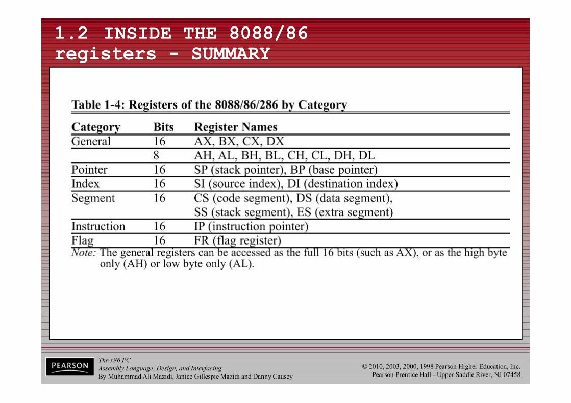
Registers of the 8086/80286 by Category
Category Bits Register Names
General 16 AX,BX,CX,DX
8 AH,AL,BH,BL,CH,CL,DH,DL
Pointer 16 SP (Stack Pointer), Base Pointer (BP)
Index 16 SI (Source Index), DI (Destination Index)
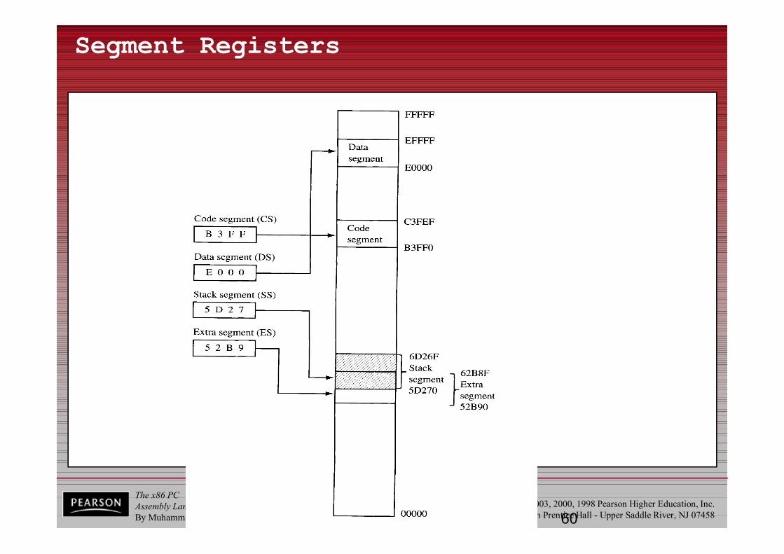
Segment 16 CS(Code Segment)DS (Data Segment)SS (Stack Segment)ES (Extra Segment)
Instruction 16 IP (Instruction Pointer)
Flag 16 FR (Flag Register)
The x86 PCAssembly Language, Design, and InterfacingBy Muhammad Ali Mazidi, Janice Gillespie Mazidi and Danny Causey
© 2010, 2003, 2000, 1998 Pearson Higher Education, Inc.Pearson Prentice Hall - Upper Saddle River, NJ 0745836
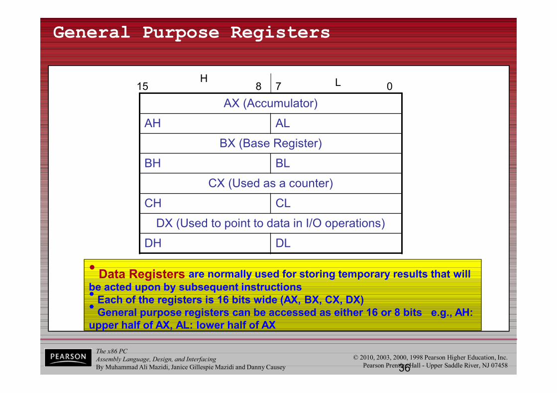
General Purpose Registers
• Data Registers are normally used for storing temporary results that will be acted upon by subsequent instructions• Each of the registers is 16 bits wide (AX, BX, CX, DX)• General purpose registers can be accessed as either 16 or 8 bits e.g., AH: upper half of AX, AL: lower half of AX
AX (Accumulator)
AH AL
BX (Base Register)
BH BL
CX (Used as a counter)
CH CL
DX (Used to point to data in I/O operations)
DH DL
15 8 7 0H L
The x86 PCAssembly Language, Design, and InterfacingBy Muhammad Ali Mazidi, Janice Gillespie Mazidi and Danny Causey
© 2010, 2003, 2000, 1998 Pearson Higher Education, Inc.Pearson Prentice Hall - Upper Saddle River, NJ 0745837
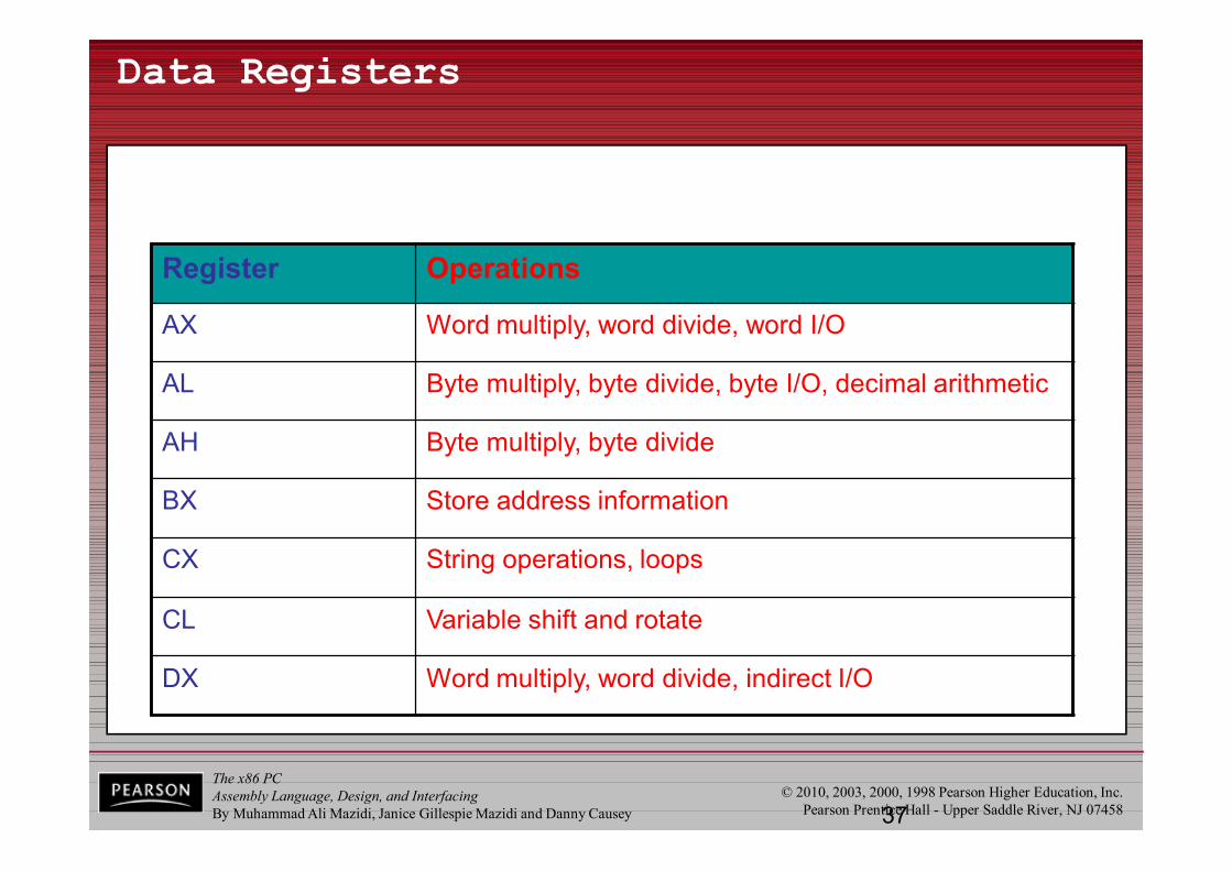
Data Registers
Register Operations
AX Word multiply, word divide, word I/O
AL Byte multiply, byte divide, byte I/O, decimal arithmetic
AH Byte multiply, byte divide
BX Store address information
CX String operations, loops
CL Variable shift and rotate
DX Word multiply, word divide, indirect I/O
The x86 PCAssembly Language, Design, and InterfacingBy Muhammad Ali Mazidi, Janice Gillespie Mazidi and Danny Causey
© 2010, 2003, 2000, 1998 Pearson Higher Education, Inc.Pearson Prentice Hall - Upper Saddle River, NJ 0745838
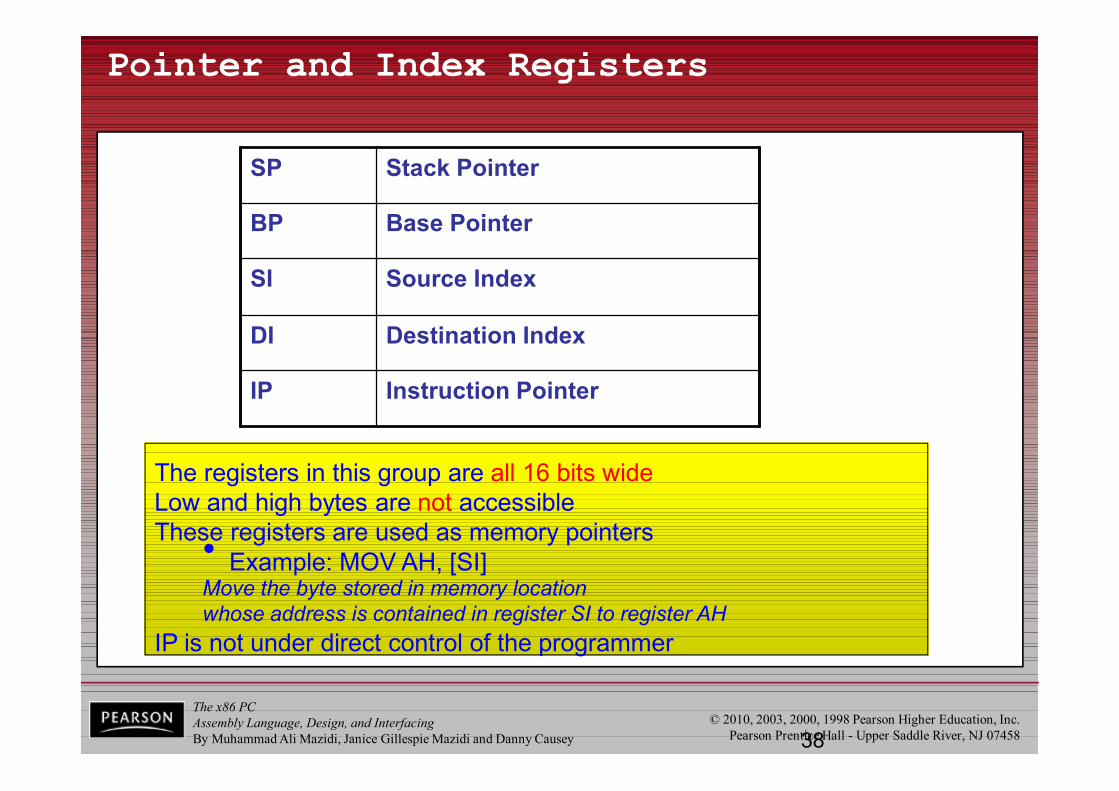
Pointer and Index Registers
The registers in this group are all 16 bits wideLow and high bytes are not accessibleThese registers are used as memory pointers• Example: MOV AH, [SI]
Move the byte stored in memory location whose address is contained in register SI to register AH
IP is not under direct control of the programmer
SP Stack Pointer
BP Base Pointer
SI Source Index
DI Destination Index
IP Instruction Pointer
The x86 PCAssembly Language, Design, and InterfacingBy Muhammad Ali Mazidi, Janice Gillespie Mazidi and Danny Causey
© 2010, 2003, 2000, 1998 Pearson Higher Education, Inc.Pearson Prentice Hall - Upper Saddle River, NJ 07458
1.2 INSIDE THE 8088/86registers - SUMMARY
The x86 PCAssembly Language, Design, and InterfacingBy Muhammad Ali Mazidi, Janice Gillespie Mazidi and Danny Causey
© 2010, 2003, 2000, 1998 Pearson Higher Education, Inc.Pearson Prentice Hall - Upper Saddle River, NJ 07458
1.3 INTRODUCTION TO ASSEMBLY PROGRAMMING
• The CPU can work only in binary, very high speeds.– It is tedious & slow for humans to deal with 0s & 1s in
order to program the computer.• A program of 0s & 1s is called machine language.
– Early computer programmers actually coded programsin machine language.
• Eventually, Assembly languages were developed, which provided mnemonics for machine code.– Mnemonic is typically used in computer science and
engineering literature to refer to codes & abbreviations that are relatively easy to remember.

The x86 PCAssembly Language, Design, and InterfacingBy Muhammad Ali Mazidi, Janice Gillespie Mazidi and Danny Causey
© 2010, 2003, 2000, 1998 Pearson Higher Education, Inc.Pearson Prentice Hall - Upper Saddle River, NJ 07458
1.3 INTRODUCTION TO ASSEMBLY PROGRAMMING
• Assembly language is referred to as a low-levellanguage because it deals directly with the internal structure of the CPU.– Assembly language programs must be translated into
machine code by a program called an assembler.– To program in Assembly language, programmers
must know the number of registers and their size.• As well as other details of the CPU.
The x86 PCAssembly Language, Design, and InterfacingBy Muhammad Ali Mazidi, Janice Gillespie Mazidi and Danny Causey
© 2010, 2003, 2000, 1998 Pearson Higher Education, Inc.Pearson Prentice Hall - Upper Saddle River, NJ 07458
1.3 INTRODUCTION TO ASSEMBLY PROGRAMMING
• Today there are many different programming languages, such as C/C++, BASIC, C#, etc.– Called high-level languages because the programmer
does not have to be concerned with internal CPU details.• High-level languages are translated into machine
code by a program called a compiler.– To write a program in C, one must use a C compiler
to translate the program into machine language.
The x86 PCAssembly Language, Design, and InterfacingBy Muhammad Ali Mazidi, Janice Gillespie Mazidi and Danny Causey
© 2010, 2003, 2000, 1998 Pearson Higher Education, Inc.Pearson Prentice Hall - Upper Saddle River, NJ 07458
1.3 INTRODUCTION TO ASSEMBLY PROGRAMMING
• There are numerous assemblers available for translating x86 Assembly language programsinto machine code.– One of the most commonly used assemblers is
MASM by Microsoft.• The present chapter is designed to correspond to
Appendix A: DEBUG Programming.– Provided with the Microsoft Windows operating system.
• We will use the emulatorsupplied on the web page x86emu.
The x86 PCAssembly Language, Design, and InterfacingBy Muhammad Ali Mazidi, Janice Gillespie Mazidi and Danny Causey
© 2010, 2003, 2000, 1998 Pearson Higher Education, Inc.Pearson Prentice Hall - Upper Saddle River, NJ 07458
1.3 INTRODUCTION TO ASSEMBLY PROGRAMMING assembly language programming
• An Assembly language program consists of a series of lines of Assembly language instructions.
• An Assembly language instruction consists of a mnemonic, optionally followed by one or two operands.– Operands are the data items being manipulated.– Mnemonics are commands to the CPU, telling it
what to do with those items.• Two widely used instructions are move & add.
The x86 PCAssembly Language, Design, and InterfacingBy Muhammad Ali Mazidi, Janice Gillespie Mazidi and Danny Causey
© 2010, 2003, 2000, 1998 Pearson Higher Education, Inc.Pearson Prentice Hall - Upper Saddle River, NJ 07458
1.3 INTRODUCTION TO ASSEMBLY PROGRAMMING MOV instruction
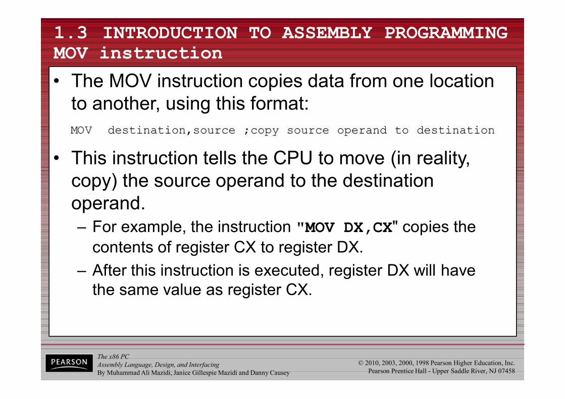
• The MOV instruction copies data from one location to another, using this format:
• This instruction tells the CPU to move (in reality, copy) the source operand to the destination operand. – For example, the instruction "MOV DX,CX" copies the
contents of register CX to register DX.– After this instruction is executed, register DX will have
the same value as register CX.
The x86 PCAssembly Language, Design, and InterfacingBy Muhammad Ali Mazidi, Janice Gillespie Mazidi and Danny Causey
© 2010, 2003, 2000, 1998 Pearson Higher Education, Inc.Pearson Prentice Hall - Upper Saddle River, NJ 07458
1.3 INTRODUCTION TO ASSEMBLY PROGRAMMING MOV instruction
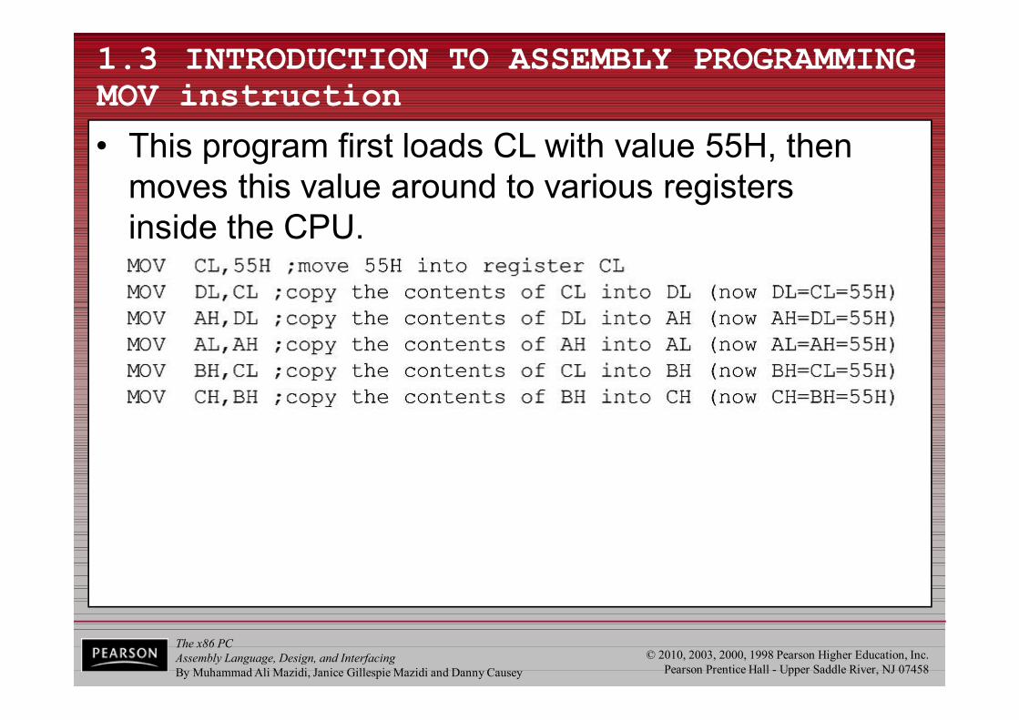
• This program first loads CL with value 55H, then moves this value around to various registersinside the CPU.
The x86 PCAssembly Language, Design, and InterfacingBy Muhammad Ali Mazidi, Janice Gillespie Mazidi and Danny Causey
© 2010, 2003, 2000, 1998 Pearson Higher Education, Inc.Pearson Prentice Hall - Upper Saddle River, NJ 07458
1.3 INTRODUCTION TO ASSEMBLY PROGRAMMING MOV instruction
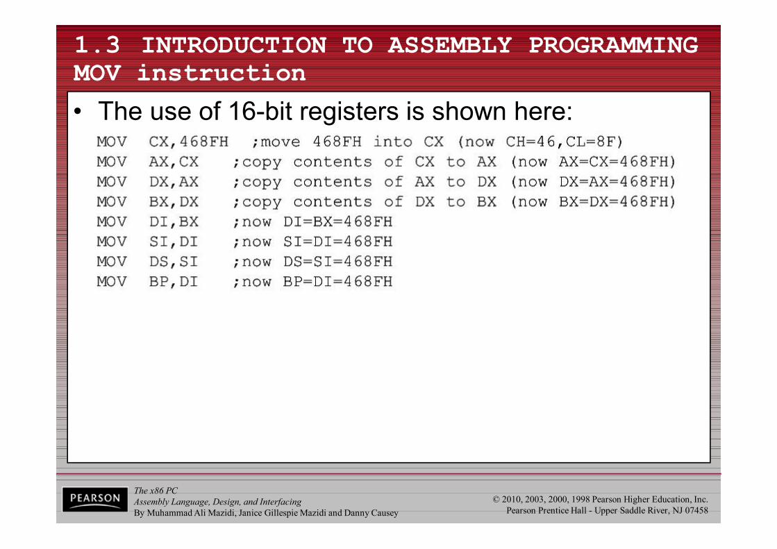
• The use of 16-bit registers is shown here:
The x86 PCAssembly Language, Design, and InterfacingBy Muhammad Ali Mazidi, Janice Gillespie Mazidi and Danny Causey
© 2010, 2003, 2000, 1998 Pearson Higher Education, Inc.Pearson Prentice Hall - Upper Saddle River, NJ 07458
1.3 INTRODUCTION TO ASSEMBLY PROGRAMMING MOV instruction
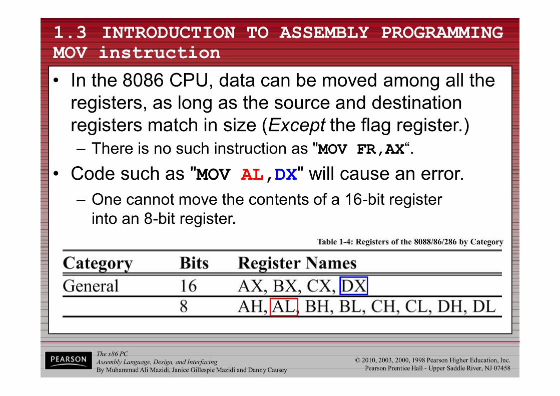
• In the 8086 CPU, data can be moved among all the registers, as long as the source and destination registers match in size (Except the flag register.)– There is no such instruction as "MOV FR,AX“.
• Code such as "MOV AL,DX" will cause an error.– One cannot move the contents of a 16-bit register
into an 8-bit register.
The x86 PCAssembly Language, Design, and InterfacingBy Muhammad Ali Mazidi, Janice Gillespie Mazidi and Danny Causey
© 2010, 2003, 2000, 1998 Pearson Higher Education, Inc.Pearson Prentice Hall - Upper Saddle River, NJ 07458
1.3 INTRODUCTION TO ASSEMBLY PROGRAMMING MOV instruction
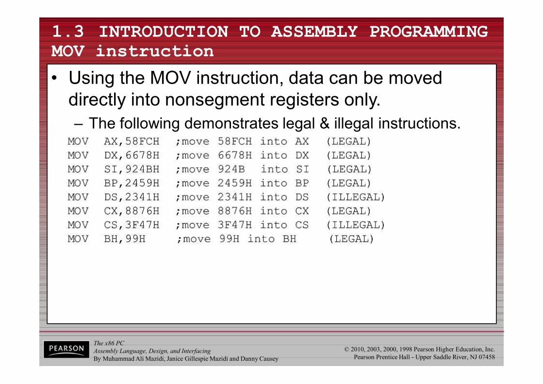
• Using the MOV instruction, data can be moved directly into nonsegment registers only.– The following demonstrates legal & illegal instructions.
The x86 PCAssembly Language, Design, and InterfacingBy Muhammad Ali Mazidi, Janice Gillespie Mazidi and Danny Causey
© 2010, 2003, 2000, 1998 Pearson Higher Education, Inc.Pearson Prentice Hall - Upper Saddle River, NJ 07458
1.3 INTRODUCTION TO ASSEMBLY PROGRAMMING MOV instruction
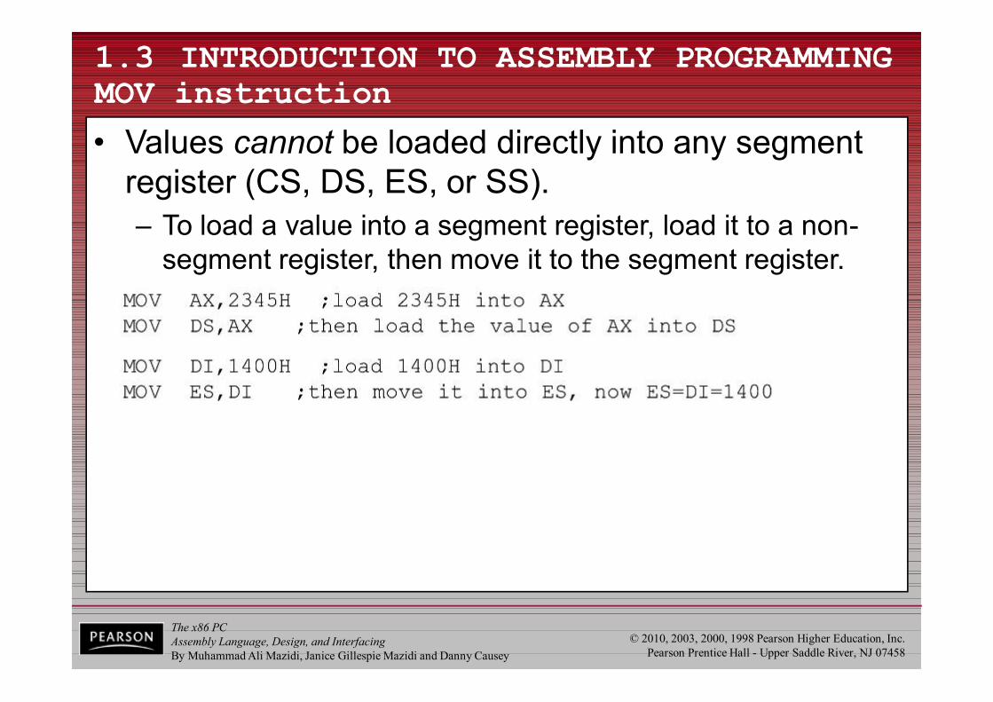
• Values cannot be loaded directly into any segment register (CS, DS, ES, or SS).– To load a value into a segment register, load it to a non-
segment register, then move it to the segment register.
The x86 PCAssembly Language, Design, and InterfacingBy Muhammad Ali Mazidi, Janice Gillespie Mazidi and Danny Causey
© 2010, 2003, 2000, 1998 Pearson Higher Education, Inc.Pearson Prentice Hall - Upper Saddle River, NJ 07458
1.3 INTRODUCTION TO ASSEMBLY PROGRAMMING MOV instruction
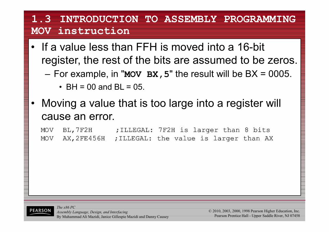
• If a value less than FFH is moved into a 16-bit register, the rest of the bits are assumed to be zeros.– For example, in "MOV BX,5" the result will be BX = 0005.
• BH = 00 and BL = 05.
• Moving a value that is too large into a register will cause an error.
The x86 PCAssembly Language, Design, and InterfacingBy Muhammad Ali Mazidi, Janice Gillespie Mazidi and Danny Causey
© 2010, 2003, 2000, 1998 Pearson Higher Education, Inc.Pearson Prentice Hall - Upper Saddle River, NJ 07458
1.3 INTRODUCTION TO ASSEMBLY PROGRAMMING ADD instruction
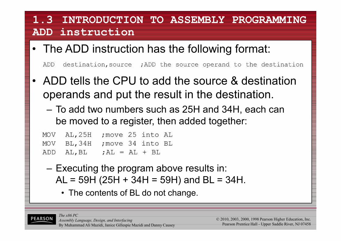
– Executing the program above results in:AL = 59H (25H + 34H = 59H) and BL = 34H.
• The contents of BL do not change.
• The ADD instruction has the following format:
• ADD tells the CPU to add the source & destination operands and put the result in the destination.– To add two numbers such as 25H and 34H, each can
be moved to a register, then added together:
The x86 PCAssembly Language, Design, and InterfacingBy Muhammad Ali Mazidi, Janice Gillespie Mazidi and Danny Causey
© 2010, 2003, 2000, 1998 Pearson Higher Education, Inc.Pearson Prentice Hall - Upper Saddle River, NJ 07458
1.3 INTRODUCTION TO ASSEMBLY PROGRAMMING ADD instruction
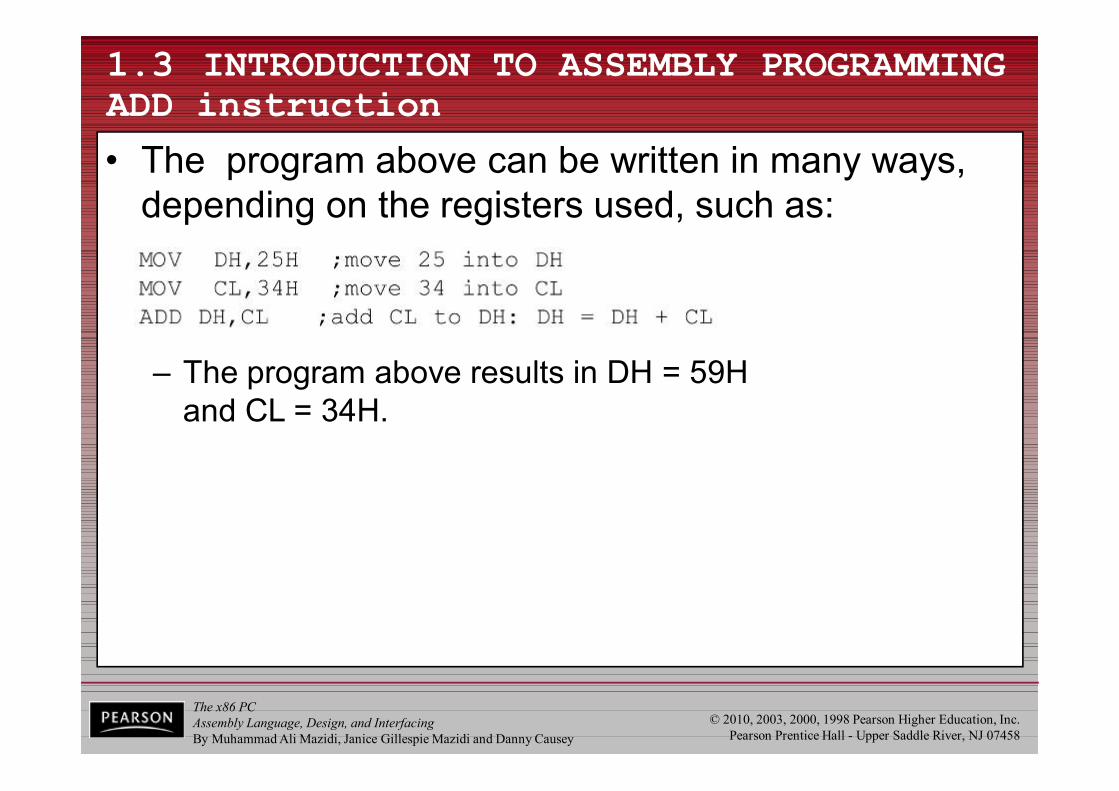
• The program above can be written in many ways, depending on the registers used, such as:
– The program above results in DH = 59Hand CL = 34H.
The x86 PCAssembly Language, Design, and InterfacingBy Muhammad Ali Mazidi, Janice Gillespie Mazidi and Danny Causey
© 2010, 2003, 2000, 1998 Pearson Higher Education, Inc.Pearson Prentice Hall - Upper Saddle River, NJ 07458
1.3 INTRODUCTION TO ASSEMBLY PROGRAMMING ADD instruction
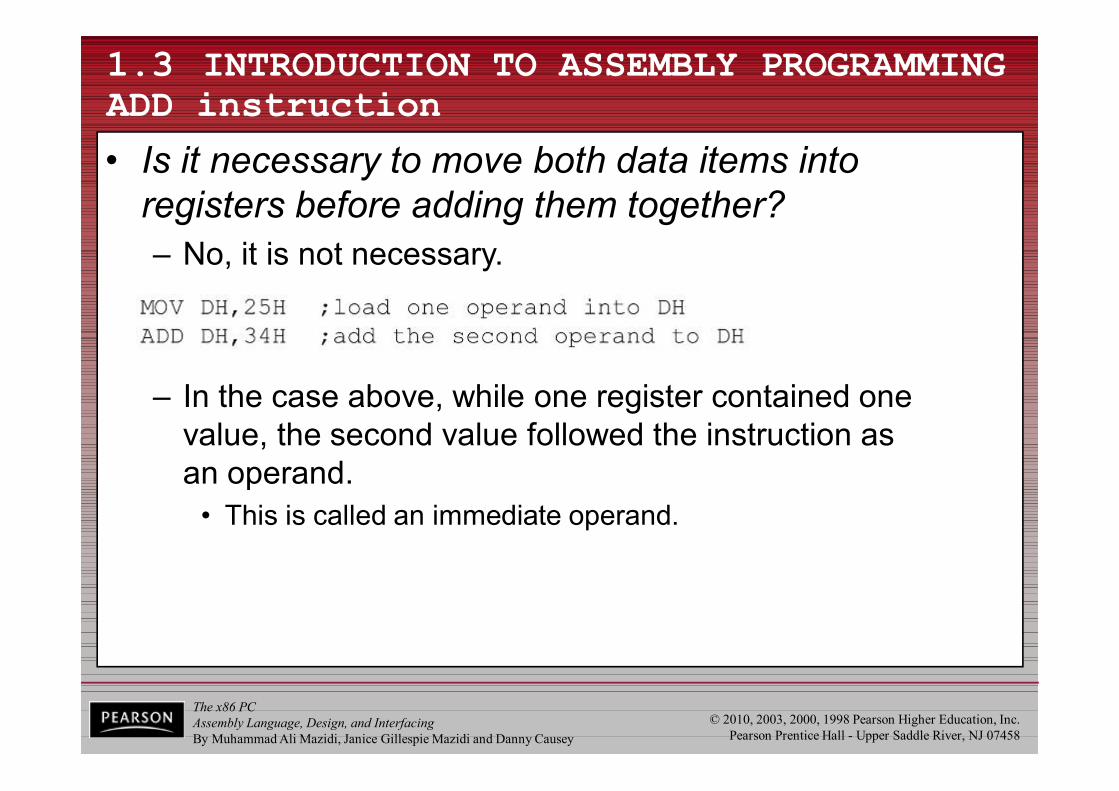
• Is it necessary to move both data items into registers before adding them together?– No, it is not necessary.
– In the case above, while one register contained one value, the second value followed the instruction asan operand.
• This is called an immediate operand.
The x86 PCAssembly Language, Design, and InterfacingBy Muhammad Ali Mazidi, Janice Gillespie Mazidi and Danny Causey
© 2010, 2003, 2000, 1998 Pearson Higher Education, Inc.Pearson Prentice Hall - Upper Saddle River, NJ 07458
1.3 INTRODUCTION TO ASSEMBLY PROGRAMMING ADD instruction
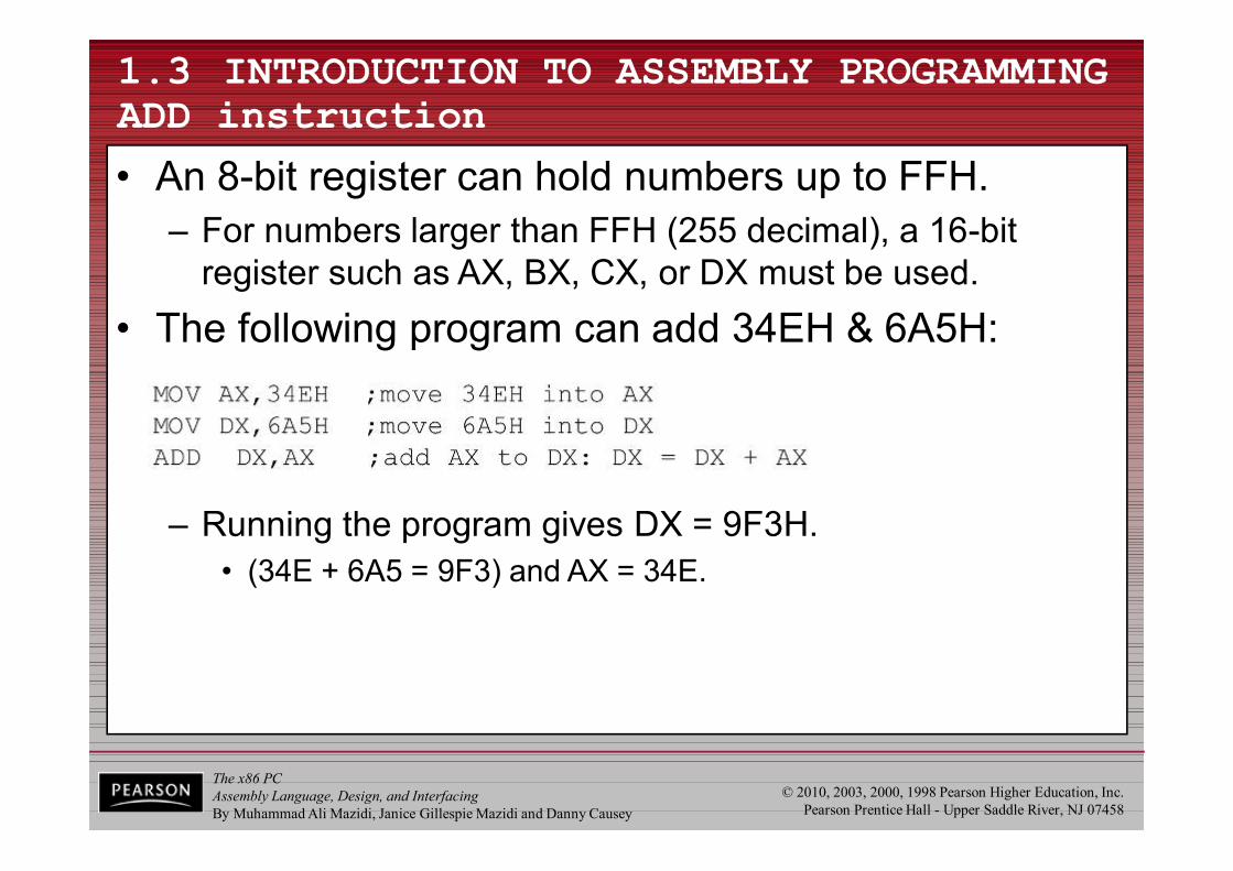
• An 8-bit register can hold numbers up to FFH.– For numbers larger than FFH (255 decimal), a 16-bit
register such as AX, BX, CX, or DX must be used.• The following program can add 34EH & 6A5H:
– Running the program gives DX = 9F3H.• (34E + 6A5 = 9F3) and AX = 34E.
The x86 PCAssembly Language, Design, and InterfacingBy Muhammad Ali Mazidi, Janice Gillespie Mazidi and Danny Causey
© 2010, 2003, 2000, 1998 Pearson Higher Education, Inc.Pearson Prentice Hall - Upper Saddle River, NJ 07458
1.3 INTRODUCTION TO ASSEMBLY PROGRAMMING ADD instruction
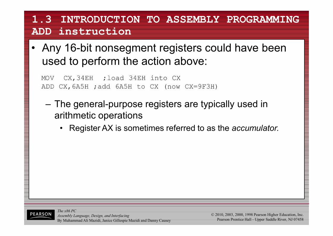
• Any 16-bit nonsegment registers could have been used to perform the action above:
– The general-purpose registers are typically used in arithmetic operations
• Register AX is sometimes referred to as the accumulator.

The x86 PCAssembly Language, Design, and InterfacingBy Muhammad Ali Mazidi, Janice Gillespie Mazidi and Danny Causey
© 2010, 2003, 2000, 1998 Pearson Higher Education, Inc.Pearson Prentice Hall - Upper Saddle River, NJ 07458
1.4 INTRODUCTION TO PROGRAM SEGMENTS
• A typical Assembly language program consists ofat least three segments:– A code segment - which contains the Assembly
language instructions that perform the tasks that the program was designed to accomplish.
– A data segment - used to store information (data) tobe processed by the instructions in the code segment.
– A stack segment - used by the CPU to store information temporarily.
The x86 PCAssembly Language, Design, and InterfacingBy Muhammad Ali Mazidi, Janice Gillespie Mazidi and Danny Causey
© 2010, 2003, 2000, 1998 Pearson Higher Education, Inc.Pearson Prentice Hall - Upper Saddle River, NJ 07458
1.4 INTRODUCTION TO PROGRAM SEGMENTS origin and definition of the segment
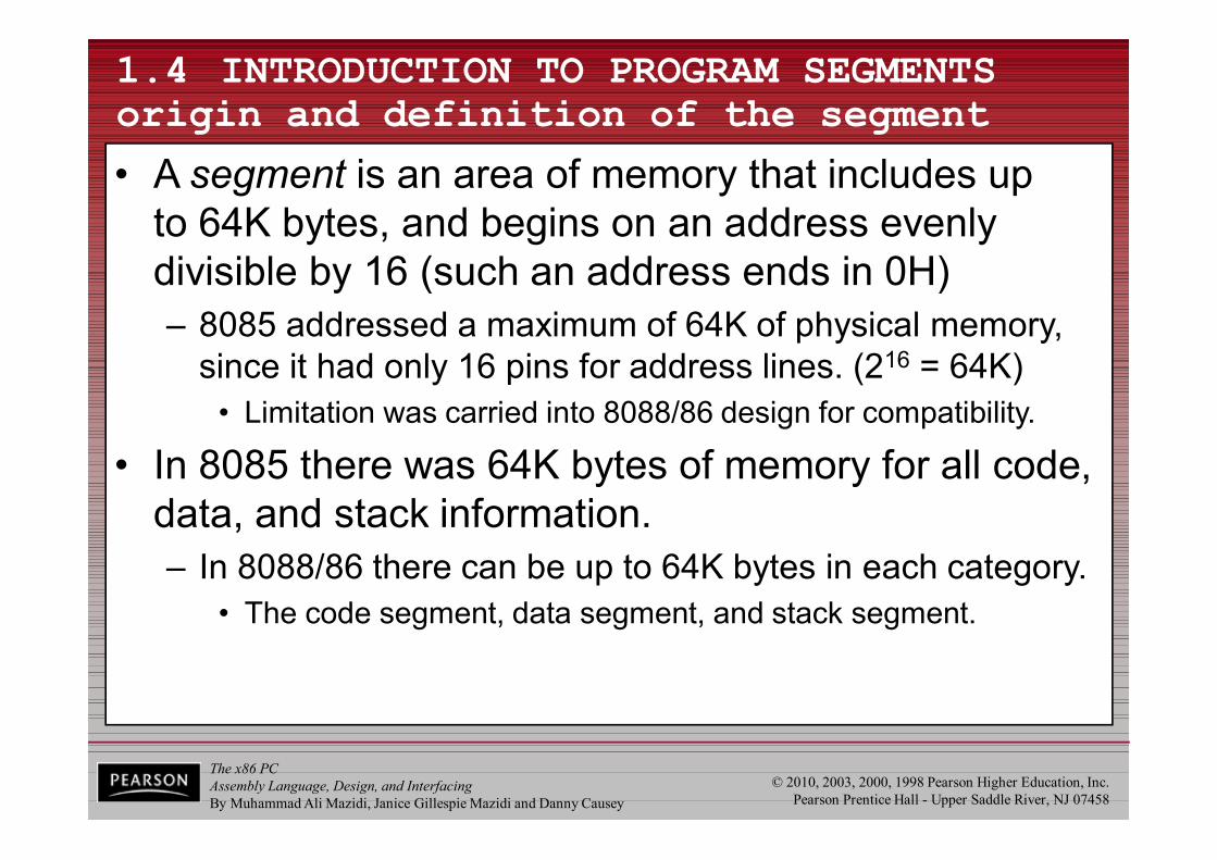
• A segment is an area of memory that includes upto 64K bytes, and begins on an address evenly divisible by 16 (such an address ends in 0H)– 8085 addressed a maximum of 64K of physical memory,
since it had only 16 pins for address lines. (216 = 64K)• Limitation was carried into 8088/86 design for compatibility.
• In 8085 there was 64K bytes of memory for all code, data, and stack information.– In 8088/86 there can be up to 64K bytes in each category.
• The code segment, data segment, and stack segment.

The x86 PCAssembly Language, Design, and InterfacingBy Muhammad Ali Mazidi, Janice Gillespie Mazidi and Danny Causey
© 2010, 2003, 2000, 1998 Pearson Higher Education, Inc.Pearson Prentice Hall - Upper Saddle River, NJ 0745859
Advantages of Segmented Memory
• One program can work on several different sets of data. This is done by reloading register DS to a new value.
• Programs that reference logical addresses can be loaded and run anywhere in the memory: relocatable
• Segmented memory introduces extra complexity in both hardware in that memory addresses require two registers.
• They also require complexity in software in that programs are limited to the segment size
• Programs greater than 64 KB can be run on 8086 but the software needed is more complex as it must switch to a new segment.
• Protection among segments is provided.
The x86 PCAssembly Language, Design, and InterfacingBy Muhammad Ali Mazidi, Janice Gillespie Mazidi and Danny Causey
© 2010, 2003, 2000, 1998 Pearson Higher Education, Inc.Pearson Prentice Hall - Upper Saddle River, NJ 0745860
Segment Registers

The x86 PCAssembly Language, Design, and InterfacingBy Muhammad Ali Mazidi, Janice Gillespie Mazidi and Danny Causey
© 2010, 2003, 2000, 1998 Pearson Higher Education, Inc.Pearson Prentice Hall - Upper Saddle River, NJ 07458
1.4 INTRODUCTION TO PROGRAM SEGMENTS logical address and physical address
• In literature concerning 8086, there are three types of addresses mentioned frequently:– The physical address - the 20-bit address actually on
the address pins of the 8086 processor, decoded by the memory interfacing circuitry.
• This address can have a range of 00000H to FFFFFH.• An actual physical location in RAM or ROM within the 1 mb
memory range.– The offset address - a location in a 64K-byte segment
range, which can can range from 0000H to FFFFH.– The logical address - which consists of a segment value
and an offset address.
The x86 PCAssembly Language, Design, and InterfacingBy Muhammad Ali Mazidi, Janice Gillespie Mazidi and Danny Causey
© 2010, 2003, 2000, 1998 Pearson Higher Education, Inc.Pearson Prentice Hall - Upper Saddle River, NJ 0745862
Logical and Physical Addresses
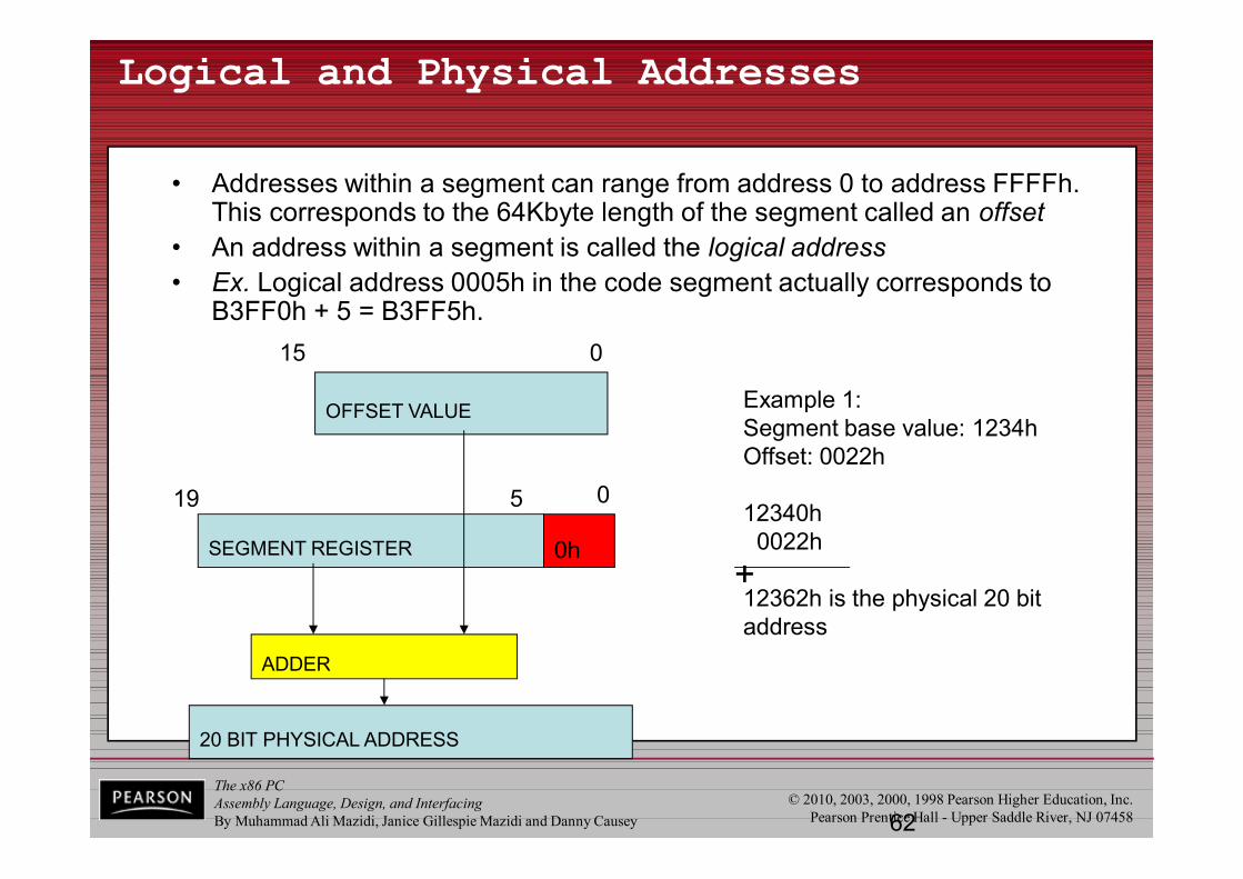
• Addresses within a segment can range from address 0 to address FFFFh. This corresponds to the 64Kbyte length of the segment called an offset
• An address within a segment is called the logical address• Ex. Logical address 0005h in the code segment actually corresponds to
B3FF0h + 5 = B3FF5h.
OFFSET VALUE
15 0
SEGMENT REGISTER 0h
0519
ADDER
20 BIT PHYSICAL ADDRESS
Example 1:Segment base value: 1234hOffset: 0022h
12340h0022h
12362h is the physical 20 bit address
+
The x86 PCAssembly Language, Design, and InterfacingBy Muhammad Ali Mazidi, Janice Gillespie Mazidi and Danny Causey
© 2010, 2003, 2000, 1998 Pearson Higher Education, Inc.Pearson Prentice Hall - Upper Saddle River, NJ 0745863
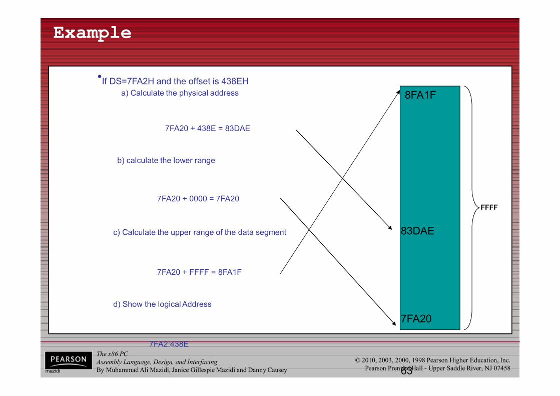
•If DS=7FA2H and the offset is 438EHa) Calculate the physical address
FFFF
Example
b) calculate the lower range
c) Calculate the upper range of the data segment
d) Show the logical Address
7FA2:438E
7FA20 + 438E = 83DAE
83DAE
7FA20 + FFFF = 8FA1F
8FA1F
7FA20 + 0000 = 7FA20
7FA20
mazidi
The x86 PCAssembly Language, Design, and InterfacingBy Muhammad Ali Mazidi, Janice Gillespie Mazidi and Danny Causey
© 2010, 2003, 2000, 1998 Pearson Higher Education, Inc.Pearson Prentice Hall - Upper Saddle River, NJ 0745864
Example
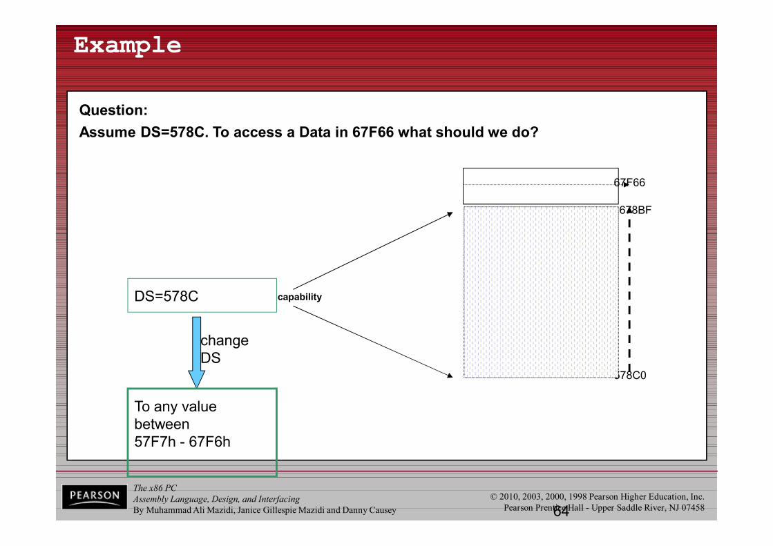
Question:Assume DS=578C. To access a Data in 67F66 what should we do?
578C0
678BF
DS=578C capability
67F66
change DS
To any value between57F7h - 67F6h
The x86 PCAssembly Language, Design, and InterfacingBy Muhammad Ali Mazidi, Janice Gillespie Mazidi and Danny Causey
© 2010, 2003, 2000, 1998 Pearson Higher Education, Inc.Pearson Prentice Hall - Upper Saddle River, NJ 0745865
Another Example
• What would be the offset required to map to physical address location 002C3H if the contents of the corresponding segment register is 002AH?
• Solution: the offset value can be obtained by shifting the contents of the segment register left by four bit positions and then subtracting from the physical address. Shifting gives:002A0H
Now subtracting, we get the value of the offset:002C3H-002A0H=0023H
The x86 PCAssembly Language, Design, and InterfacingBy Muhammad Ali Mazidi, Janice Gillespie Mazidi and Danny Causey
© 2010, 2003, 2000, 1998 Pearson Higher Education, Inc.Pearson Prentice Hall - Upper Saddle River, NJ 07458
1.4 INTRODUCTION TO PROGRAM SEGMENTS code segment
• To execute a program, 8086 fetches the instructions (opcodes and operands) from the code segment.– The logical address of an instruction always consists of a
CS (code segment) and an IP (instruction pointer), shown in CS:IP format.
– The physical address for the location of the instructionis generated by shifting the CS left one hex digit, then adding it to the IP.
• IP contains the offset address.
• The resulting 20-bit address is called the physical address since it is put on the external physical address bus pins.
The x86 PCAssembly Language, Design, and InterfacingBy Muhammad Ali Mazidi, Janice Gillespie Mazidi and Danny Causey
© 2010, 2003, 2000, 1998 Pearson Higher Education, Inc.Pearson Prentice Hall - Upper Saddle River, NJ 07458
1.4 INTRODUCTION TO PROGRAM SEGMENTS code segment
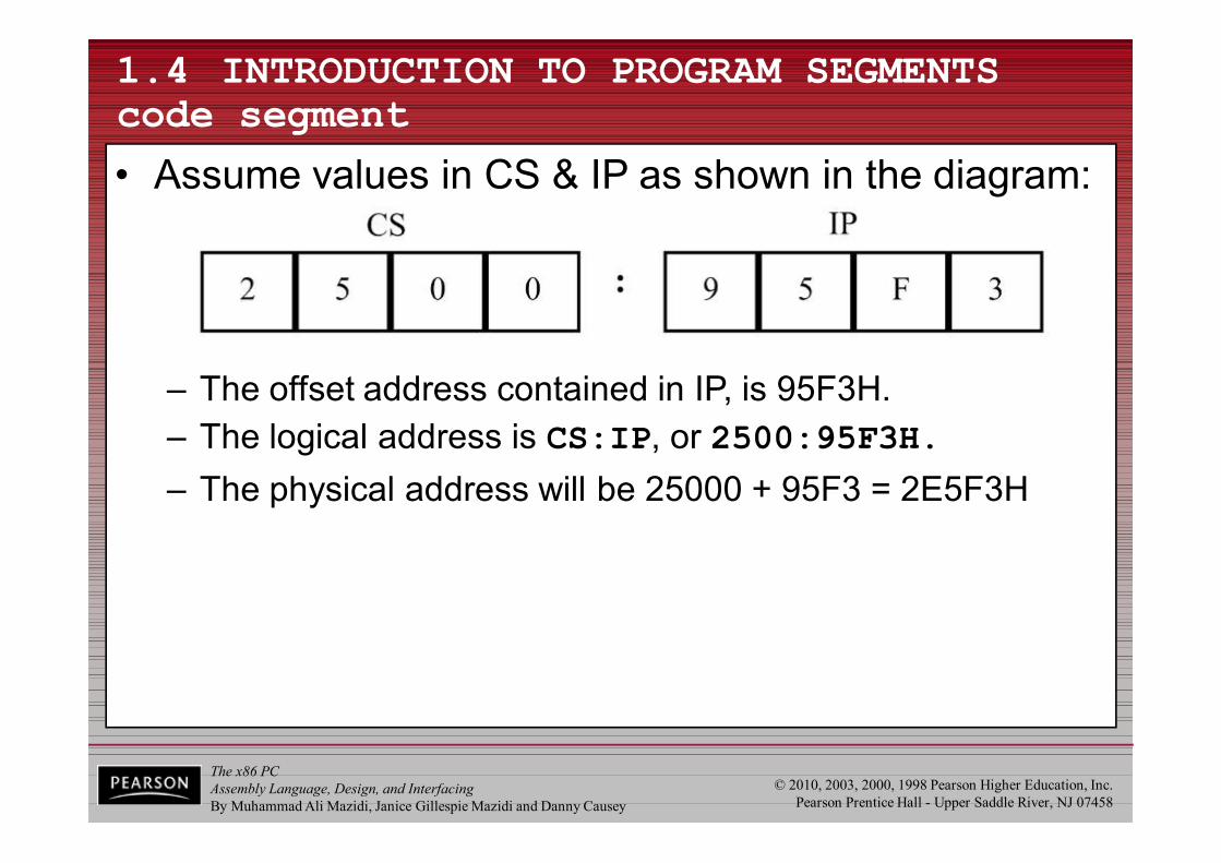
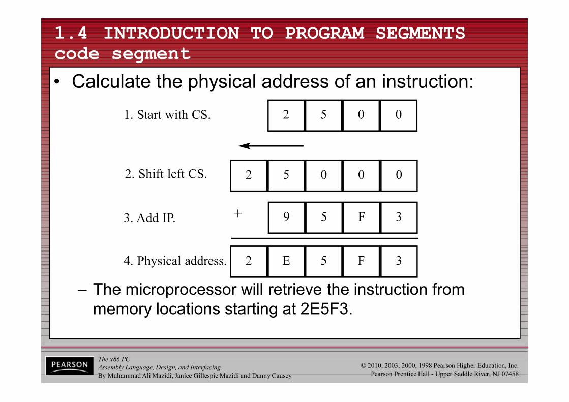
• Assume values in CS & IP as shown in the diagram:
– The offset address contained in IP, is 95F3H.– The logical address is CS:IP, or 2500:95F3H.– The physical address will be 25000 + 95F3 = 2E5F3H
The x86 PCAssembly Language, Design, and InterfacingBy Muhammad Ali Mazidi, Janice Gillespie Mazidi and Danny Causey
© 2010, 2003, 2000, 1998 Pearson Higher Education, Inc.Pearson Prentice Hall - Upper Saddle River, NJ 07458
1.4 INTRODUCTION TO PROGRAM SEGMENTS code segment
• Calculate the physical address of an instruction:
– The microprocessor will retrieve the instruction from memory locations starting at 2E5F3.
The x86 PCAssembly Language, Design, and InterfacingBy Muhammad Ali Mazidi, Janice Gillespie Mazidi and Danny Causey
© 2010, 2003, 2000, 1998 Pearson Higher Education, Inc.Pearson Prentice Hall - Upper Saddle River, NJ 07458
1.4 INTRODUCTION TO PROGRAM SEGMENTS code segment
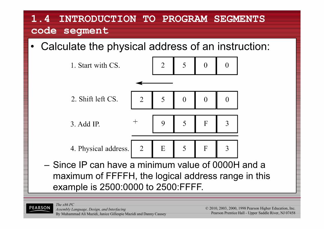
• Calculate the physical address of an instruction:
– Since IP can have a minimum value of 0000H and a maximum of FFFFH, the logical address range in this example is 2500:0000 to 2500:FFFF.
The x86 PCAssembly Language, Design, and InterfacingBy Muhammad Ali Mazidi, Janice Gillespie Mazidi and Danny Causey
© 2010, 2003, 2000, 1998 Pearson Higher Education, Inc.Pearson Prentice Hall - Upper Saddle River, NJ 07458
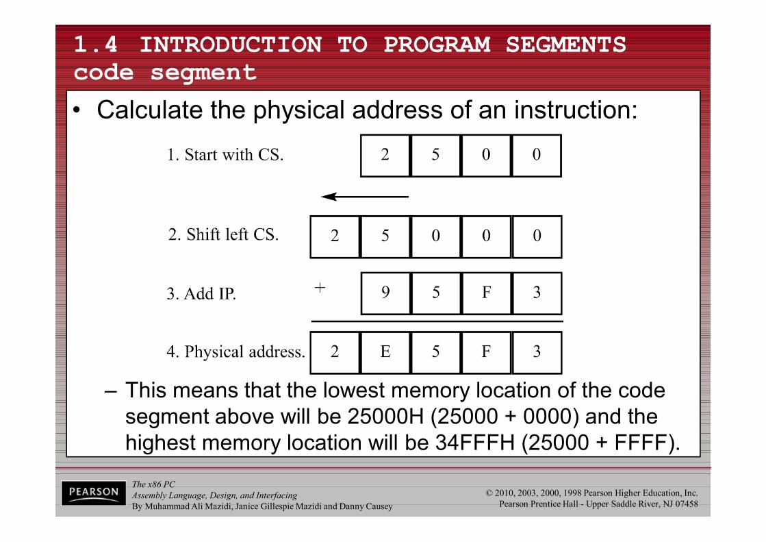
– This means that the lowest memory location of the code segment above will be 25000H (25000 + 0000) and the highest memory location will be 34FFFH (25000 + FFFF).
1.4 INTRODUCTION TO PROGRAM SEGMENTS code segment
• Calculate the physical address of an instruction:
The x86 PCAssembly Language, Design, and InterfacingBy Muhammad Ali Mazidi, Janice Gillespie Mazidi and Danny Causey
© 2010, 2003, 2000, 1998 Pearson Higher Education, Inc.Pearson Prentice Hall - Upper Saddle River, NJ 07458
1.4 INTRODUCTION TO PROGRAM SEGMENTS code segment
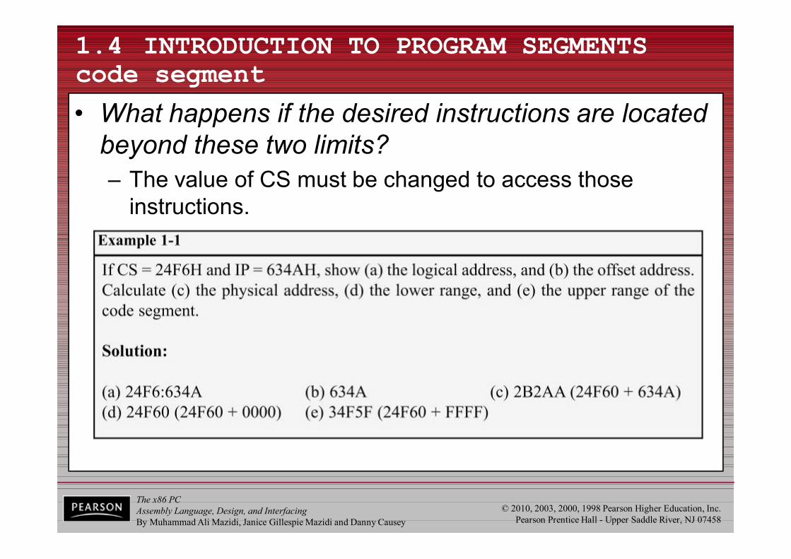
• What happens if the desired instructions are located beyond these two limits? – The value of CS must be changed to access those
instructions.
The x86 PCAssembly Language, Design, and InterfacingBy Muhammad Ali Mazidi, Janice Gillespie Mazidi and Danny Causey
© 2010, 2003, 2000, 1998 Pearson Higher Education, Inc.Pearson Prentice Hall - Upper Saddle River, NJ 07458
1.4 INTRODUCTION TO PROGRAM SEGMENTS code segment logical/physical address
• In the next code segment, CS and IP hold the logical address of the instructions to be executed.– The following Assembly language instructions have been
assembled (translated into machine code) and stored in memory.
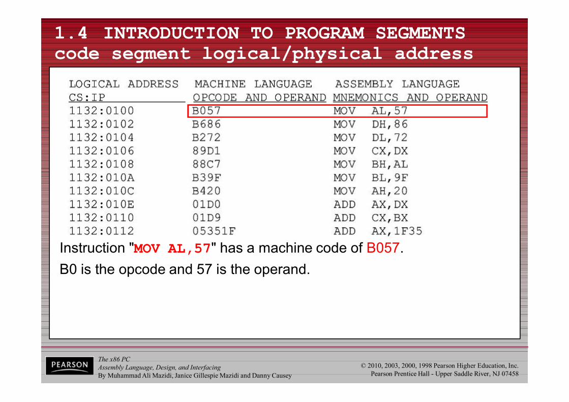
– The three columns show the logical address of CS:IP, the machine code stored at that address, and the corresponding Assembly language code.
– The physical address is put on the address bus by the CPU to be decoded by the memory circuitry.
The x86 PCAssembly Language, Design, and InterfacingBy Muhammad Ali Mazidi, Janice Gillespie Mazidi and Danny Causey
© 2010, 2003, 2000, 1998 Pearson Higher Education, Inc.Pearson Prentice Hall - Upper Saddle River, NJ 07458
1.4 INTRODUCTION TO PROGRAM SEGMENTS code segment logical/physical address
Instruction "MOV AL,57" has a machine code of B057.B0 is the opcode and 57 is the operand.
The x86 PCAssembly Language, Design, and InterfacingBy Muhammad Ali Mazidi, Janice Gillespie Mazidi and Danny Causey
© 2010, 2003, 2000, 1998 Pearson Higher Education, Inc.Pearson Prentice Hall - Upper Saddle River, NJ 0745874
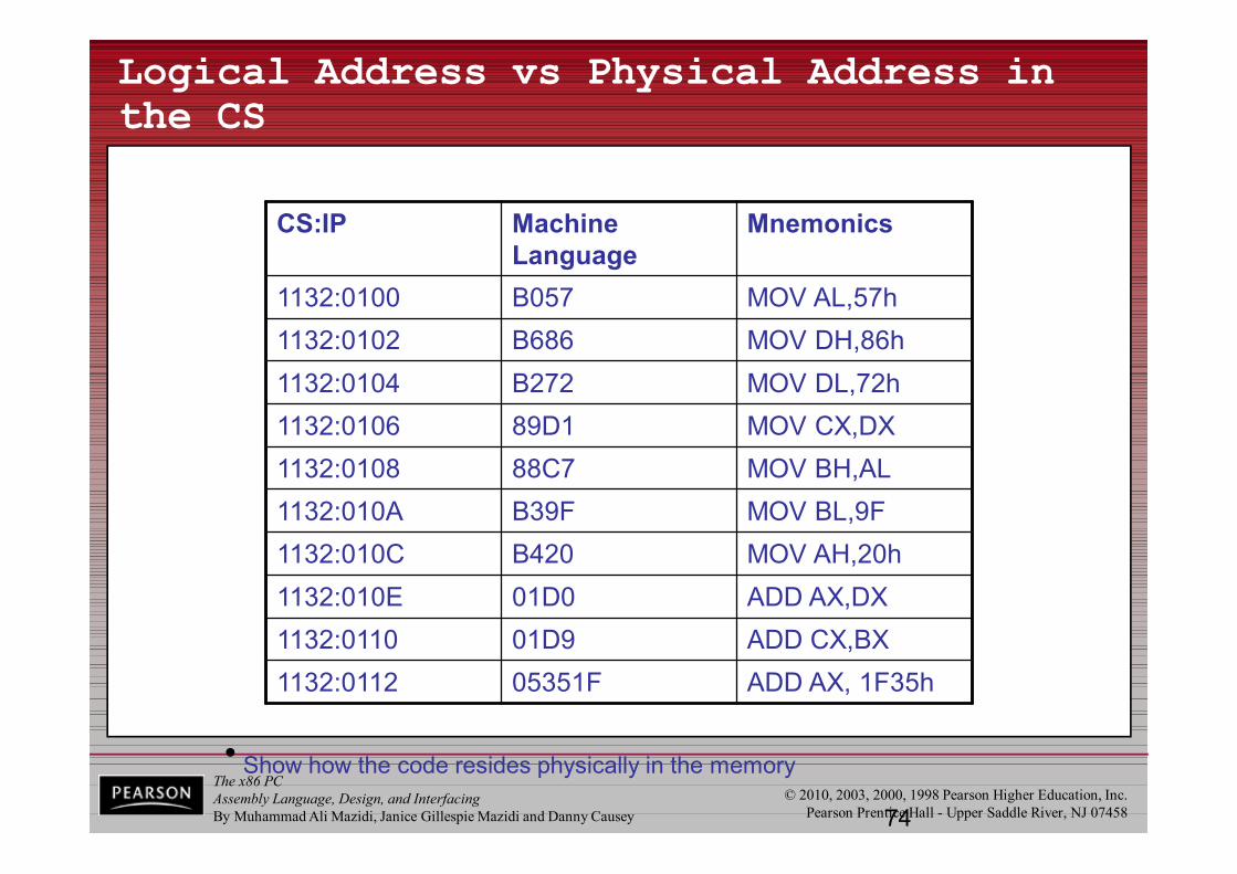
Logical Address vs Physical Address in the CS
CS:IP Machine Language
Mnemonics
1132:0100 B057 MOV AL,57h1132:0102 B686 MOV DH,86h1132:0104 B272 MOV DL,72h1132:0106 89D1 MOV CX,DX1132:0108 88C7 MOV BH,AL1132:010A B39F MOV BL,9F1132:010C B420 MOV AH,20h1132:010E 01D0 ADD AX,DX1132:0110 01D9 ADD CX,BX1132:0112 05351F ADD AX, 1F35h
• Show how the code resides physically in the memory

The x86 PCAssembly Language, Design, and InterfacingBy Muhammad Ali Mazidi, Janice Gillespie Mazidi and Danny Causey
© 2010, 2003, 2000, 1998 Pearson Higher Education, Inc.Pearson Prentice Hall - Upper Saddle River, NJ 07458
1.4 INTRODUCTION TO PROGRAM SEGMENTS code segment logical/physical address
Instruction "MOV AL,57" has a machine code of B057.B0 is the opcode and 57 is the operand.The byte at address 1132:0100 contains B0, the opcode for movinga value into register AL.Address 1132:0101 contains the operand to be moved to AL.
The x86 PCAssembly Language, Design, and InterfacingBy Muhammad Ali Mazidi, Janice Gillespie Mazidi and Danny Causey
© 2010, 2003, 2000, 1998 Pearson Higher Education, Inc.Pearson Prentice Hall - Upper Saddle River, NJ 07458
1.4 INTRODUCTION TO PROGRAM SEGMENTS data segment
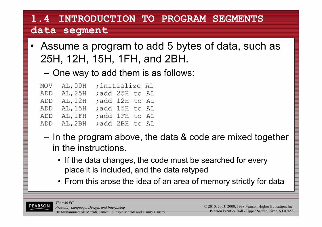
• Assume a program to add 5 bytes of data, such as 25H, 12H, 15H, 1FH, and 2BH.– One way to add them is as follows:
– In the program above, the data & code are mixed together in the instructions.
• If the data changes, the code must be searched for every place it is included, and the data retyped
• From this arose the idea of an area of memory strictly for data

The x86 PCAssembly Language, Design, and InterfacingBy Muhammad Ali Mazidi, Janice Gillespie Mazidi and Danny Causey
© 2010, 2003, 2000, 1998 Pearson Higher Education, Inc.Pearson Prentice Hall - Upper Saddle River, NJ 07458
1.4 INTRODUCTION TO PROGRAM SEGMENTS data segment
• In x86 microprocessors, the area of memory set aside for data is called the data segment.– The data segment uses register DS and an offset value.– DEBUG assumes that all numbers are in hex.
• No "H" suffix is required.– MASM assumes that they are in decimal.
• The "H" must be included for hex data.
• The next program demonstrates how data canbe stored in the data segment and the programrewritten so that it can be used for any set of data.
The x86 PCAssembly Language, Design, and InterfacingBy Muhammad Ali Mazidi, Janice Gillespie Mazidi and Danny Causey
© 2010, 2003, 2000, 1998 Pearson Higher Education, Inc.Pearson Prentice Hall - Upper Saddle River, NJ 07458
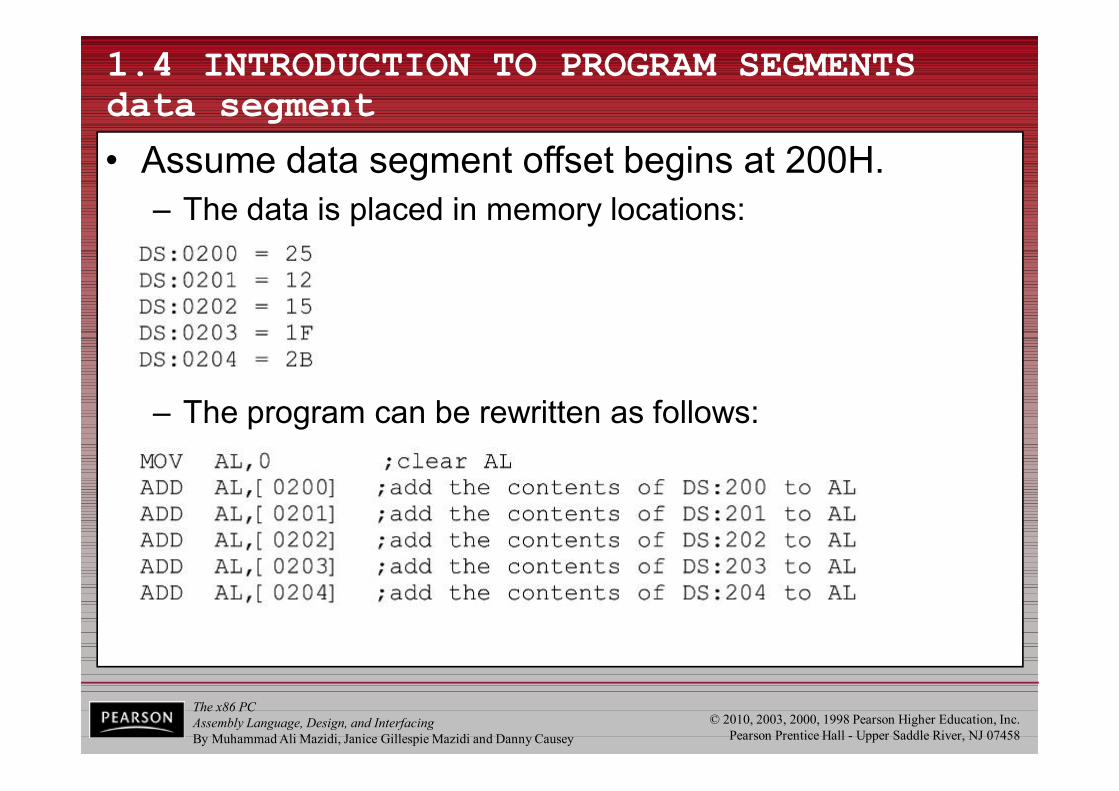
1.4 INTRODUCTION TO PROGRAM SEGMENTS data segment
• Assume data segment offset begins at 200H.– The data is placed in memory locations:
– The program can be rewritten as follows:
The x86 PCAssembly Language, Design, and InterfacingBy Muhammad Ali Mazidi, Janice Gillespie Mazidi and Danny Causey
© 2010, 2003, 2000, 1998 Pearson Higher Education, Inc.Pearson Prentice Hall - Upper Saddle River, NJ 07458
1.4 INTRODUCTION TO PROGRAM SEGMENTS data segment
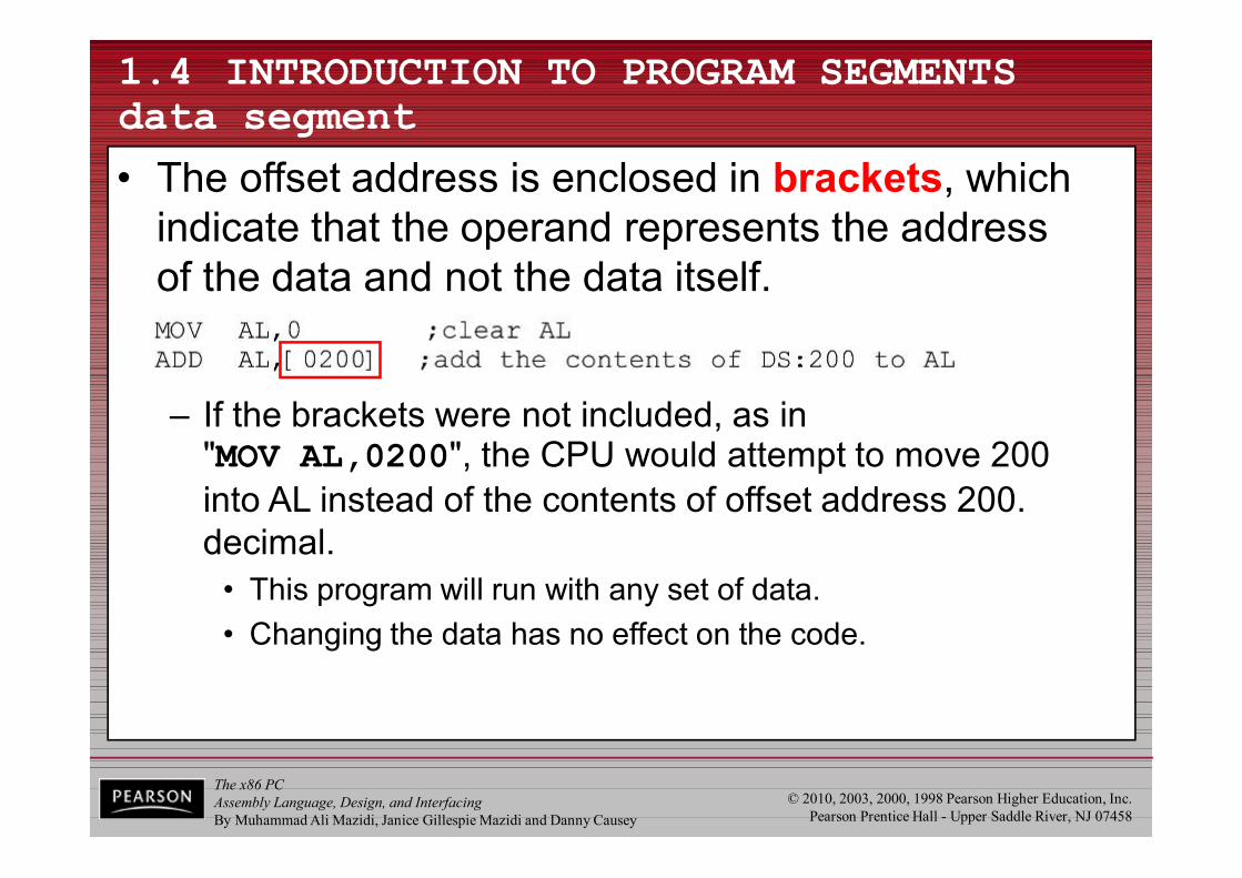
• The offset address is enclosed in brackets, which indicate that the operand represents the addressof the data and not the data itself.
– If the brackets were not included, as in "MOV AL,0200", the CPU would attempt to move 200 into AL instead of the contents of offset address 200. decimal.
• This program will run with any set of data.• Changing the data has no effect on the code.
The x86 PCAssembly Language, Design, and InterfacingBy Muhammad Ali Mazidi, Janice Gillespie Mazidi and Danny Causey
© 2010, 2003, 2000, 1998 Pearson Higher Education, Inc.Pearson Prentice Hall - Upper Saddle River, NJ 07458
1.4 INTRODUCTION TO PROGRAM SEGMENTS data segment
• If the data had to be stored at a different offset address the program would have to be rewritten– A way to solve this problem is to use a register to hold
the offset address, and before each ADD, increment the register to access the next byte.
• 8088/86 allows only the use of registers BX, SI, and DI as offset registers for the data segment– The term pointer is often used for a register holding
an offset address.
The x86 PCAssembly Language, Design, and InterfacingBy Muhammad Ali Mazidi, Janice Gillespie Mazidi and Danny Causey
© 2010, 2003, 2000, 1998 Pearson Higher Education, Inc.Pearson Prentice Hall - Upper Saddle River, NJ 07458
1.4 INTRODUCTION TO PROGRAM SEGMENTS data segment
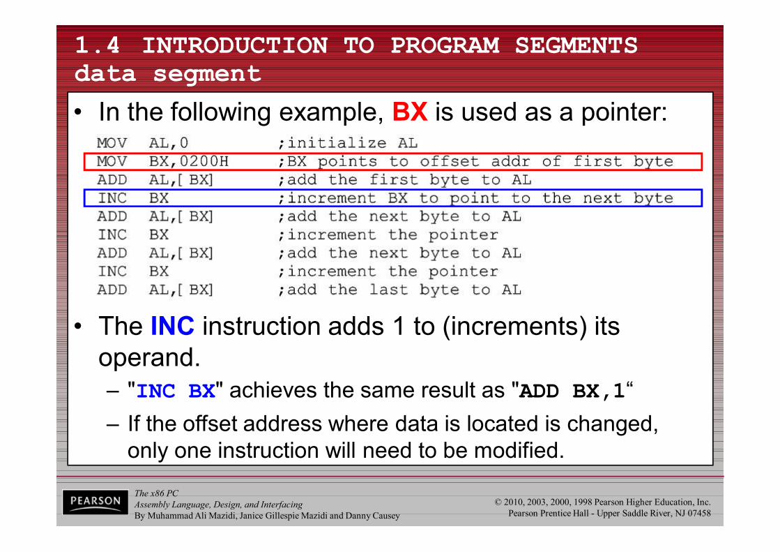
• In the following example, BX is used as a pointer:
• The INC instruction adds 1 to (increments) its operand.– "INC BX" achieves the same result as "ADD BX,1“– If the offset address where data is located is changed,
only one instruction will need to be modified.
The x86 PCAssembly Language, Design, and InterfacingBy Muhammad Ali Mazidi, Janice Gillespie Mazidi and Danny Causey
© 2010, 2003, 2000, 1998 Pearson Higher Education, Inc.Pearson Prentice Hall - Upper Saddle River, NJ 07458
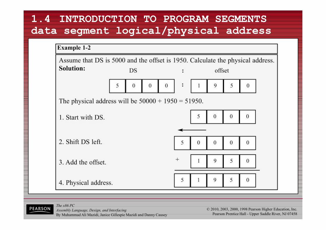
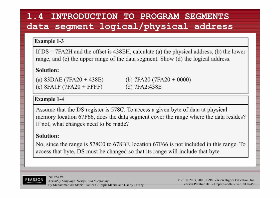
1.4 INTRODUCTION TO PROGRAM SEGMENTS data segment logical/physical address
• The physical address for data is calculated using the same rules as for the code segment.– The physical address of data is calculated by shifting DS
left one hex digit and adding the offset value, as shownin Examples 1-2, 1-3, and 1-4.
The x86 PCAssembly Language, Design, and InterfacingBy Muhammad Ali Mazidi, Janice Gillespie Mazidi and Danny Causey
© 2010, 2003, 2000, 1998 Pearson Higher Education, Inc.Pearson Prentice Hall - Upper Saddle River, NJ 07458
1.4 INTRODUCTION TO PROGRAM SEGMENTS data segment logical/physical address
The x86 PCAssembly Language, Design, and InterfacingBy Muhammad Ali Mazidi, Janice Gillespie Mazidi and Danny Causey
© 2010, 2003, 2000, 1998 Pearson Higher Education, Inc.Pearson Prentice Hall - Upper Saddle River, NJ 07458
1.4 INTRODUCTION TO PROGRAM SEGMENTS data segment logical/physical address
The x86 PCAssembly Language, Design, and InterfacingBy Muhammad Ali Mazidi, Janice Gillespie Mazidi and Danny Causey
© 2010, 2003, 2000, 1998 Pearson Higher Education, Inc.Pearson Prentice Hall - Upper Saddle River, NJ 07458
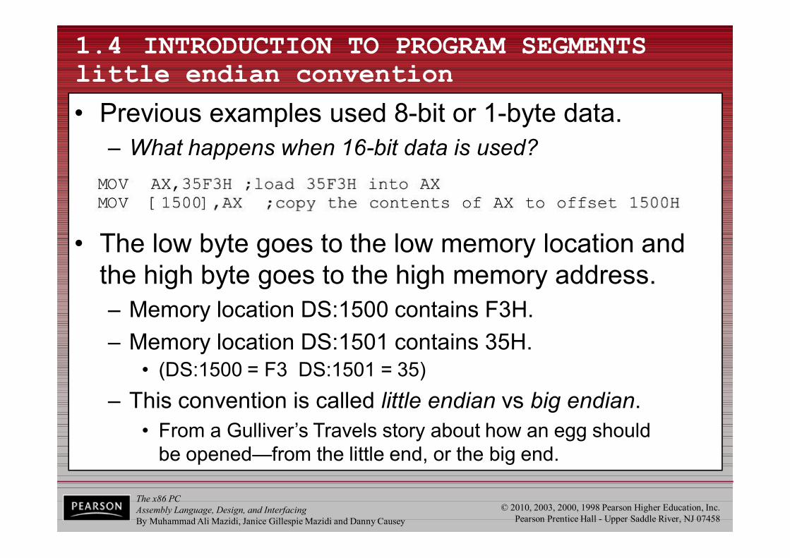
1.4 INTRODUCTION TO PROGRAM SEGMENTS little endian convention
• Previous examples used 8-bit or 1-byte data.– What happens when 16-bit data is used?
• The low byte goes to the low memory location and the high byte goes to the high memory address.– Memory location DS:1500 contains F3H.– Memory location DS:1501 contains 35H.
• (DS:1500 = F3 DS:1501 = 35)– This convention is called little endian vs big endian.
• From a Gulliver’s Travels story about how an egg shouldbe opened—from the little end, or the big end.
The x86 PCAssembly Language, Design, and InterfacingBy Muhammad Ali Mazidi, Janice Gillespie Mazidi and Danny Causey
© 2010, 2003, 2000, 1998 Pearson Higher Education, Inc.Pearson Prentice Hall - Upper Saddle River, NJ 07458
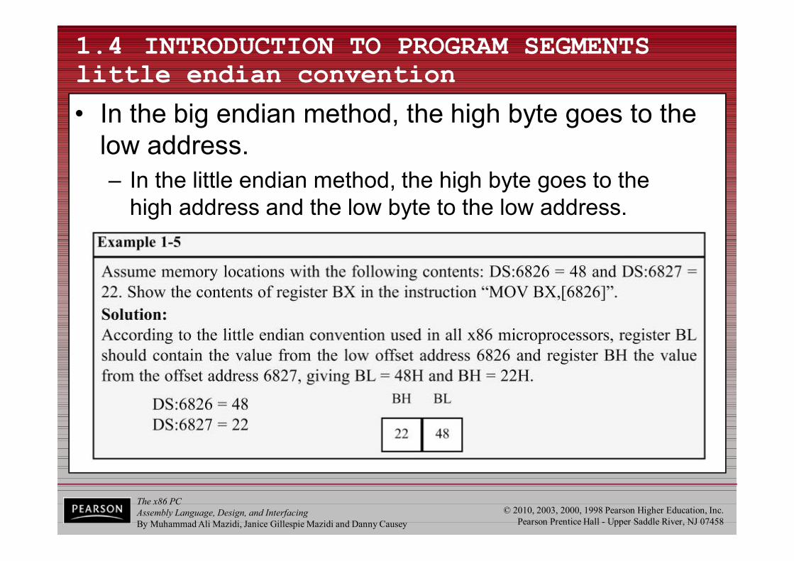
1.4 INTRODUCTION TO PROGRAM SEGMENTS little endian convention
• In the big endian method, the high byte goes to the low address.– In the little endian method, the high byte goes to the
high address and the low byte to the low address.

The x86 PCAssembly Language, Design, and InterfacingBy Muhammad Ali Mazidi, Janice Gillespie Mazidi and Danny Causey
© 2010, 2003, 2000, 1998 Pearson Higher Education, Inc.Pearson Prentice Hall - Upper Saddle River, NJ 07458
1.4 INTRODUCTION TO PROGRAM SEGMENTS little endian convention
• All Intel microprocessors and many microcontrollers use the little endian convention.– Freescale (formerly Motorola) microprocessors, along
with some other microcontrollers, use big endian.
The x86 PCAssembly Language, Design, and InterfacingBy Muhammad Ali Mazidi, Janice Gillespie Mazidi and Danny Causey
© 2010, 2003, 2000, 1998 Pearson Higher Education, Inc.Pearson Prentice Hall - Upper Saddle River, NJ 07458
1.4 INTRODUCTION TO PROGRAM SEGMENTS extra segment (ES)
• ES is a segment register used as an extra data segment.– In many normal programs this segment is not used.– Use is essential for string operations.
The x86 PCAssembly Language, Design, and InterfacingBy Muhammad Ali Mazidi, Janice Gillespie Mazidi and Danny Causey
© 2010, 2003, 2000, 1998 Pearson Higher Education, Inc.Pearson Prentice Hall - Upper Saddle River, NJ 0745889
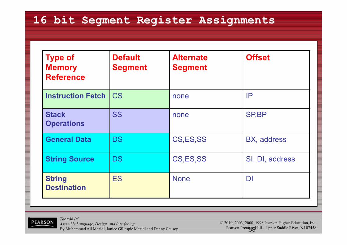
16 bit Segment Register Assignments
Type of Memory Reference
Default Segment
Alternate Segment
Offset
Instruction Fetch CS none IP
Stack Operations
SS none SP,BP
General Data DS CS,ES,SS BX, address
String Source DS CS,ES,SS SI, DI, address
String Destination
ES None DI
Brey

The x86 PCAssembly Language, Design, and InterfacingBy Muhammad Ali Mazidi, Janice Gillespie Mazidi and Danny Causey
© 2010, 2003, 2000, 1998 Pearson Higher Education, Inc.Pearson Prentice Hall - Upper Saddle River, NJ 07458
1.4 INTRODUCTION TO PROGRAM SEGMENTS memory map of the IBM PC
• The 20-bit address of 8088/86 allows 1mb (1024K bytes) of memory space with the address range 00000–FFFFF.– During the design phase of the first
IBM PC, engineers had to decideon the allocation of the 1-megabyte memory space to various sectionsof the PC.
• This memory allocation iscalled a memory map.
Figure 1-3 Memory Allocation in the PC
The x86 PCAssembly Language, Design, and InterfacingBy Muhammad Ali Mazidi, Janice Gillespie Mazidi and Danny Causey
© 2010, 2003, 2000, 1998 Pearson Higher Education, Inc.Pearson Prentice Hall - Upper Saddle River, NJ 07458
Figure 1-3 Memory Allocation in the PC
1.4 INTRODUCTION TO PROGRAM SEGMENTS memory map of the IBM PC
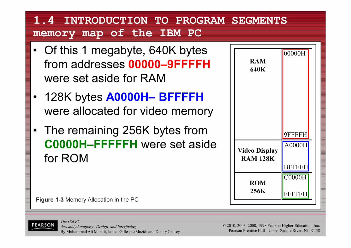
• Of this 1 megabyte, 640K bytes from addresses 00000–9FFFFHwere set aside for RAM
• 128K bytes A0000H– BFFFFHwere allocated for video memory
• The remaining 256K bytes from C0000H–FFFFFH were set aside for ROM
The x86 PCAssembly Language, Design, and InterfacingBy Muhammad Ali Mazidi, Janice Gillespie Mazidi and Danny Causey
© 2010, 2003, 2000, 1998 Pearson Higher Education, Inc.Pearson Prentice Hall - Upper Saddle River, NJ 07458
1.4 INTRODUCTION TO PROGRAM SEGMENTS more about RAM
• In the early 80s, most PCs came with 64K to 256K bytes of RAM, more than adequate at the time– Users had to buy memory to expand up to 640K.
• Managing RAM is left to Windows because...– The amount of memory used by Windows varies.– Different computers have different amounts of RAM.– Memory needs of application packages vary.
• For this reason, we do not assign any values for the CS, DS, and SS registers.– Such an assignment means specifying an exact physical
address in the range 00000–9FFFFH, and this is beyond the knowledge of the user.
The x86 PCAssembly Language, Design, and InterfacingBy Muhammad Ali Mazidi, Janice Gillespie Mazidi and Danny Causey
© 2010, 2003, 2000, 1998 Pearson Higher Education, Inc.Pearson Prentice Hall - Upper Saddle River, NJ 07458
1.4 INTRODUCTION TO PROGRAM SEGMENTS video RAM
• From A0000H to BFFFFH is set aside for video– The amount used and the location vary depending
on the video board installed on the PC
The x86 PCAssembly Language, Design, and InterfacingBy Muhammad Ali Mazidi, Janice Gillespie Mazidi and Danny Causey
© 2010, 2003, 2000, 1998 Pearson Higher Education, Inc.Pearson Prentice Hall - Upper Saddle River, NJ 07458
1.4 INTRODUCTION TO PROGRAM SEGMENTS more about ROM
• C0000H to FFFFFH is set aside for ROM.– Not all the memory in this range is used by the PC's ROM.
• 64K bytes from location F0000H–FFFFFH areused by BIOS (basic input/output system) ROM.– Some of the remaining space is used by various adapter
cards (such as the network card), and the rest is free.• The 640K bytes from 00000 to 9FFFFH is referred
to as conventional memory.– The 384K bytes from A0000H to FFFFFH are called
the UMB (upper memory block).
The x86 PCAssembly Language, Design, and InterfacingBy Muhammad Ali Mazidi, Janice Gillespie Mazidi and Danny Causey
© 2010, 2003, 2000, 1998 Pearson Higher Education, Inc.Pearson Prentice Hall - Upper Saddle River, NJ 07458
1.4 INTRODUCTION TO PROGRAM SEGMENTS function of BIOS ROM
• There must be some permanent (nonvolatile) memory to hold the programs telling the CPUwhat to do when the power is turned on– This collection of programs is referred to as BIOS.
• BIOS stands for basic input-output system.– It contains programs to test RAM and other
components connected to the CPU.– It also contains programs that allow Windows to
communicate with peripheral devices.– The BIOS tests devices connected to the PC when
the computer is turned on and to report any errors.
The x86 PCAssembly Language, Design, and InterfacingBy Muhammad Ali Mazidi, Janice Gillespie Mazidi and Danny Causey
© 2010, 2003, 2000, 1998 Pearson Higher Education, Inc.Pearson Prentice Hall - Upper Saddle River, NJ 07458
1.6 FLAG REGISTER
• Many Assembly language instructions alter flag register bits & some instructions function differently based on the information in the flag register.
• The flag register is a 16-bit register sometimes referred to as the status register.– Although 16 bits wide, only some of the bits are used.
• The rest are either undefined or reserved by Intel.
The x86 PCAssembly Language, Design, and InterfacingBy Muhammad Ali Mazidi, Janice Gillespie Mazidi and Danny Causey
© 2010, 2003, 2000, 1998 Pearson Higher Education, Inc.Pearson Prentice Hall - Upper Saddle River, NJ 07458
1.6 FLAG REGISTER
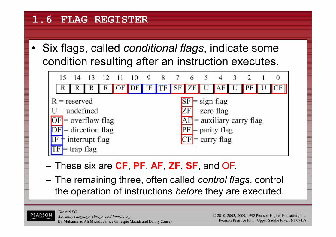
• Six flags, called conditional flags, indicate some condition resulting after an instruction executes.
– These six are CF, PF, AF, ZF, SF, and OF.– The remaining three, often called control flags, control
the operation of instructions before they are executed.

The x86 PCAssembly Language, Design, and InterfacingBy Muhammad Ali Mazidi, Janice Gillespie Mazidi and Danny Causey
© 2010, 2003, 2000, 1998 Pearson Higher Education, Inc.Pearson Prentice Hall - Upper Saddle River, NJ 07458
1.6 FLAG REGISTER bits of the flag register
• Flag register bits used in x86 Assembly language programming, with a brief explanation each:– CF (Carry Flag) - Set when there is a carry out, from d7
after an 8-bit operation, or d15 after a 16-bit operation.• Used to detect errors in unsigned arithmetic operations.
– PF (Parity Flag) - After certain operations, the parityof the result's low-order byte is checked.
• If the byte has an even number of 1s, the parity flag is set to 1; otherwise, it is cleared.
– AF (Auxiliary Carry Flag) - If there is a carry from d3 to d4 of an operation, this bit is set; otherwise, it is cleared.
• Used by instructions that perform BCD (binary codeddecimal) arithmetic.
The x86 PCAssembly Language, Design, and InterfacingBy Muhammad Ali Mazidi, Janice Gillespie Mazidi and Danny Causey
© 2010, 2003, 2000, 1998 Pearson Higher Education, Inc.Pearson Prentice Hall - Upper Saddle River, NJ 07458
1.6 FLAG REGISTER bits of the flag register
• Flag register bits used in x86 Assembly language programming, with a brief explanation each:– ZF (Zero Flag) - Set to 1 if the result of an arithmetic or
logical operation is zero; otherwise, it is cleared.– SF (Sign Flag) - Binary representation of signed numbers
uses the most significant bit as the sign bit.• After arithmetic or logic operations, the status of this sign
bit is copied into the SF, indicating the sign of the result.– TF (Trap Flag) - When this flag is set it allows the
program to single-step, meaning to execute one instruction at a time.
• Single-stepping is used for debugging purposes.
The x86 PCAssembly Language, Design, and InterfacingBy Muhammad Ali Mazidi, Janice Gillespie Mazidi and Danny Causey
© 2010, 2003, 2000, 1998 Pearson Higher Education, Inc.Pearson Prentice Hall - Upper Saddle River, NJ 07458
1.6 FLAG REGISTER bits of the flag register
• Flag register bits used in x86 Assembly language programming, with a brief explanation each:– IF (Interrupt Enable Flag) - This bit is set or cleared to
enable/disable only external maskable interrupt requests.– DF (Direction Flag) - Used to control the direction of
string operations.– OF (Overflow Flag) - Set when the result of a signed
number operation is too large, causing the high-orderbit to overflow into the sign bit.
• Used only to detect errors in signed arithmetic operations.
The x86 PCAssembly Language, Design, and InterfacingBy Muhammad Ali Mazidi, Janice Gillespie Mazidi and Danny Causey
© 2010, 2003, 2000, 1998 Pearson Higher Education, Inc.Pearson Prentice Hall - Upper Saddle River, NJ 07458
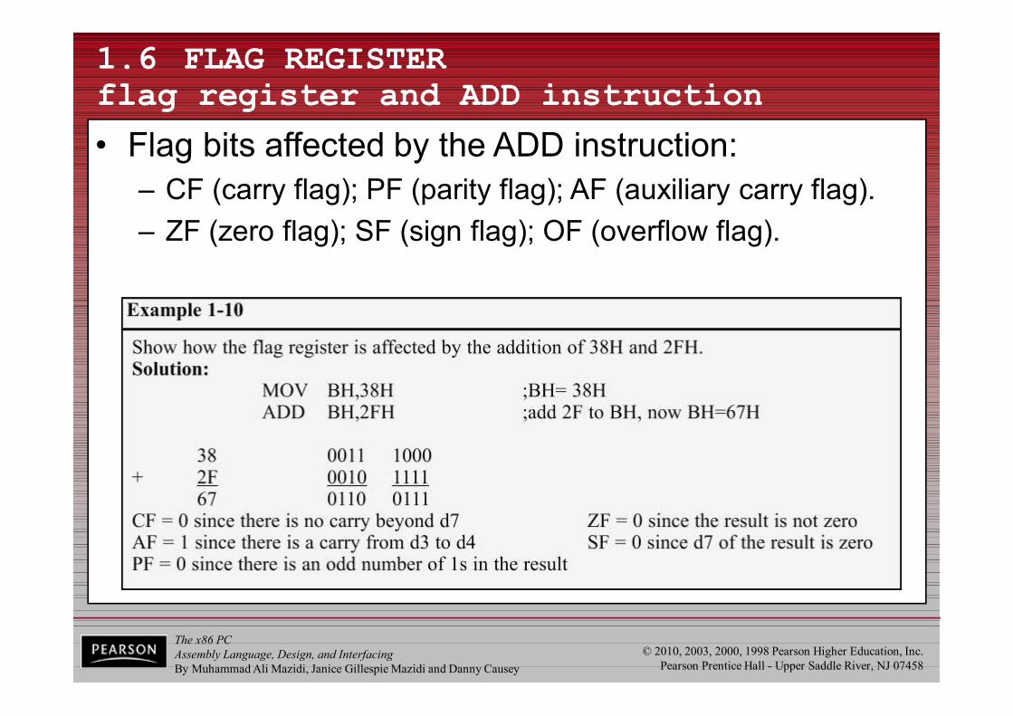
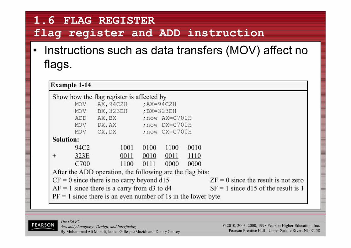
1.6 FLAG REGISTER flag register and ADD instruction
• Flag bits affected by the ADD instruction:– CF (carry flag); PF (parity flag); AF (auxiliary carry flag).– ZF (zero flag); SF (sign flag); OF (overflow flag).
The x86 PCAssembly Language, Design, and InterfacingBy Muhammad Ali Mazidi, Janice Gillespie Mazidi and Danny Causey
© 2010, 2003, 2000, 1998 Pearson Higher Education, Inc.Pearson Prentice Hall - Upper Saddle River, NJ 07458
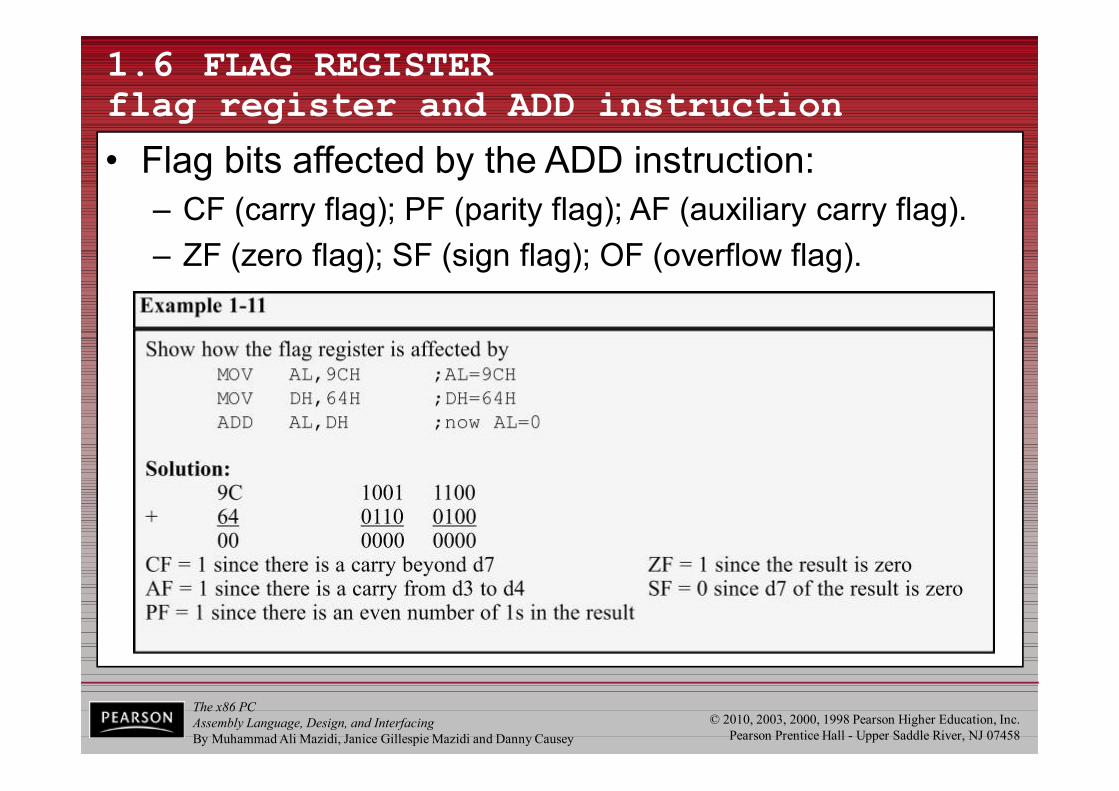
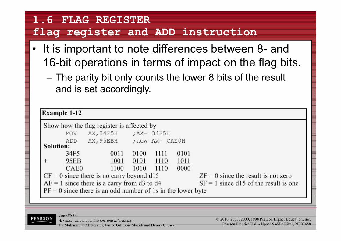
1.6 FLAG REGISTER flag register and ADD instruction
• It is important to note differences between 8- and 16-bit operations in terms of impact on the flag bits.– The parity bit only counts the lower 8 bits of the result
and is set accordingly.
The x86 PCAssembly Language, Design, and InterfacingBy Muhammad Ali Mazidi, Janice Gillespie Mazidi and Danny Causey
© 2010, 2003, 2000, 1998 Pearson Higher Education, Inc.Pearson Prentice Hall - Upper Saddle River, NJ 07458
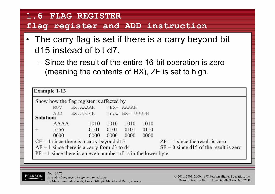
1.6 FLAG REGISTER flag register and ADD instruction
• The carry flag is set if there is a carry beyond bit d15 instead of bit d7.– Since the result of the entire 16-bit operation is zero
(meaning the contents of BX), ZF is set to high.
The x86 PCAssembly Language, Design, and InterfacingBy Muhammad Ali Mazidi, Janice Gillespie Mazidi and Danny Causey
© 2010, 2003, 2000, 1998 Pearson Higher Education, Inc.Pearson Prentice Hall - Upper Saddle River, NJ 07458
1.6 FLAG REGISTER flag register and ADD instruction
• Instructions such as data transfers (MOV) affect no flags.
The x86 PCAssembly Language, Design, and InterfacingBy Muhammad Ali Mazidi, Janice Gillespie Mazidi and Danny Causey
© 2010, 2003, 2000, 1998 Pearson Higher Education, Inc.Pearson Prentice Hall - Upper Saddle River, NJ 07458
1.6 FLAG REGISTER use of the zero flag for looping
• A widely used application of the flag register is the use of the zero flag to implement program loops.– A loop is a set of instructions repeated a number of times.
The x86 PCAssembly Language, Design, and InterfacingBy Muhammad Ali Mazidi, Janice Gillespie Mazidi and Danny Causey
© 2010, 2003, 2000, 1998 Pearson Higher Education, Inc.Pearson Prentice Hall - Upper Saddle River, NJ 07458
1.6 FLAG REGISTER use of the zero flag for looping
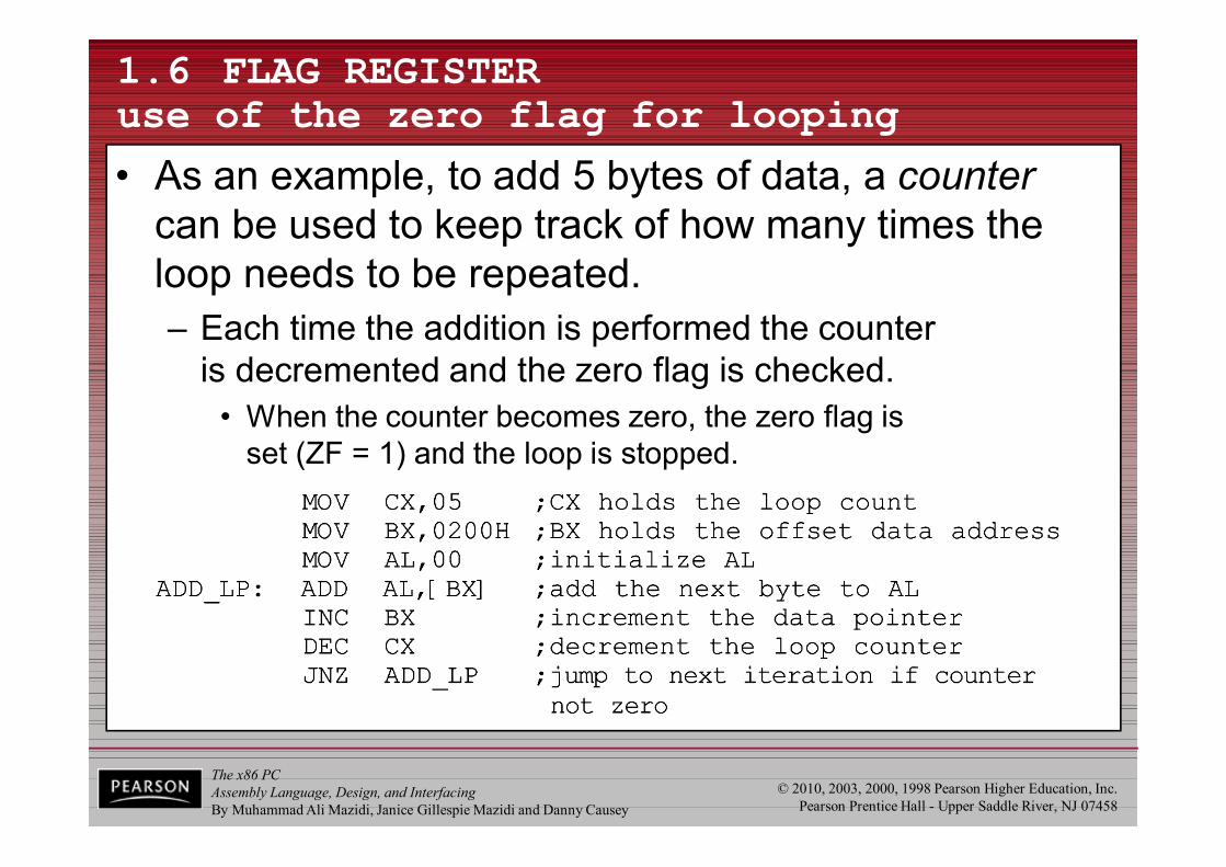
• As an example, to add 5 bytes of data, a counter can be used to keep track of how many times the loop needs to be repeated.– Each time the addition is performed the counter
is decremented and the zero flag is checked.• When the counter becomes zero, the zero flag is
set (ZF = 1) and the loop is stopped.

The x86 PCAssembly Language, Design, and InterfacingBy Muhammad Ali Mazidi, Janice Gillespie Mazidi and Danny Causey
© 2010, 2003, 2000, 1998 Pearson Higher Education, Inc.Pearson Prentice Hall - Upper Saddle River, NJ 07458
1.6 FLAG REGISTER use of the zero flag for looping
• Register CX is used to hold the counter.– BX is the offset pointer.
• (SI or DI could have been used instead)

The x86 PCAssembly Language, Design, and InterfacingBy Muhammad Ali Mazidi, Janice Gillespie Mazidi and Danny Causey
© 2010, 2003, 2000, 1998 Pearson Higher Education, Inc.Pearson Prentice Hall - Upper Saddle River, NJ 07458
1.6 FLAG REGISTER use of the zero flag for looping
• AL is initialized before the start of the loop– In each iteration, ZF is checked by the JNZ instruction
• JNZ stands for "Jump Not Zero“, meaning that if ZF = 0,jump to a new address.
• If ZF = 1, the jump is not performed, and the instructionbelow the jump will be executed.
The x86 PCAssembly Language, Design, and InterfacingBy Muhammad Ali Mazidi, Janice Gillespie Mazidi and Danny Causey
© 2010, 2003, 2000, 1998 Pearson Higher Education, Inc.Pearson Prentice Hall - Upper Saddle River, NJ 07458
1.6 FLAG REGISTER use of the zero flag for looping
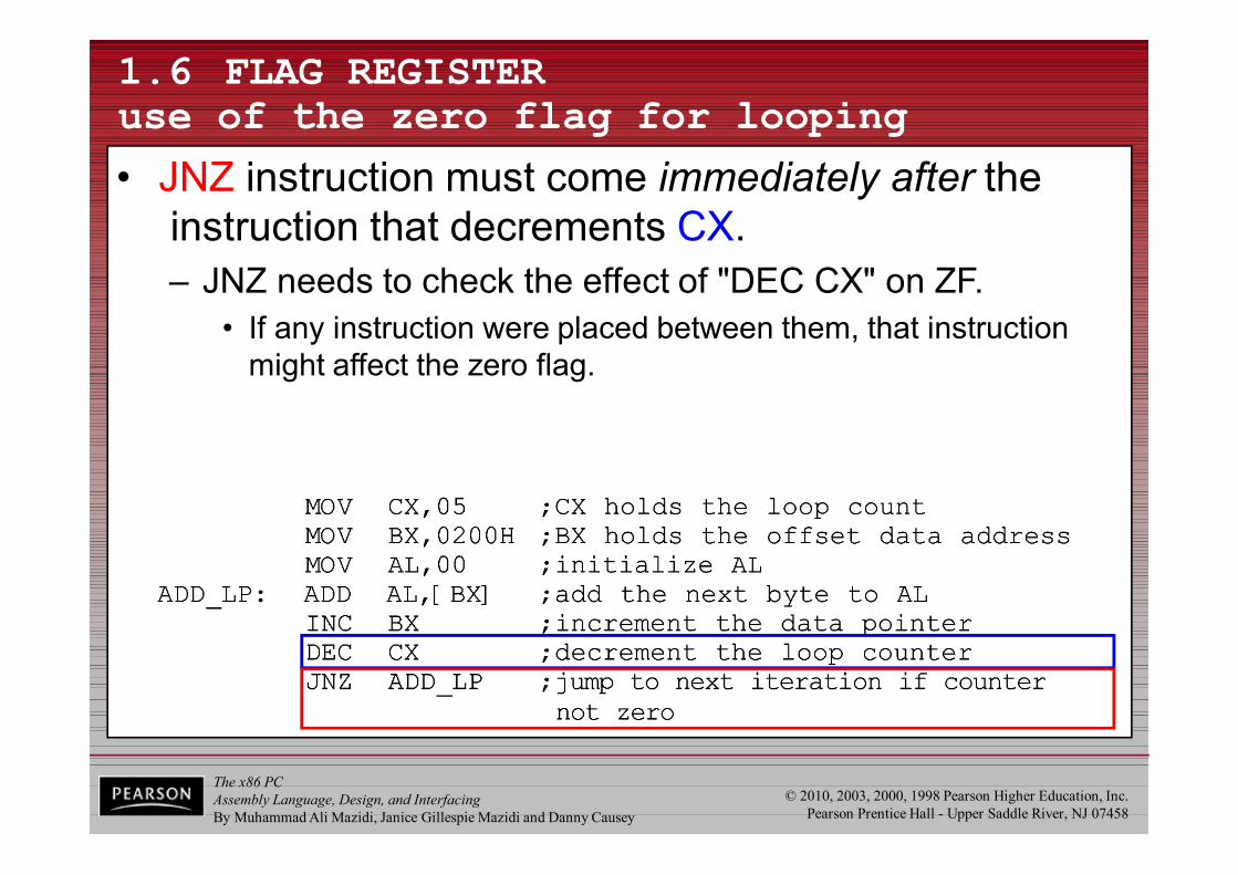
• JNZ instruction must come immediately after the instruction that decrements CX.– JNZ needs to check the effect of "DEC CX" on ZF.
• If any instruction were placed between them, that instruction might affect the zero flag.

The x86 PCAssembly Language, Design, and InterfacingBy Muhammad Ali Mazidi, Janice Gillespie Mazidi and Danny Causey
© 2010, 2003, 2000, 1998 Pearson Higher Education, Inc.Pearson Prentice Hall - Upper Saddle River, NJ 07458
1.7 x86 ADDRESSING MODES
• The CPU can access operands (data) in various ways, called addressing modes.– The number of addressing modes is determined when
the microprocessor is designed & cannot be changed• The x86 provides seven distinct addressing modes:
– 1 - Register – 2 - Immediate – 3 - Direct– 4 - Register indirect
– 5 - Based relative – 6 - Indexed relative– 7 - Based indexed relative
The x86 PCAssembly Language, Design, and InterfacingBy Muhammad Ali Mazidi, Janice Gillespie Mazidi and Danny Causey
© 2010, 2003, 2000, 1998 Pearson Higher Education, Inc.Pearson Prentice Hall - Upper Saddle River, NJ 07458
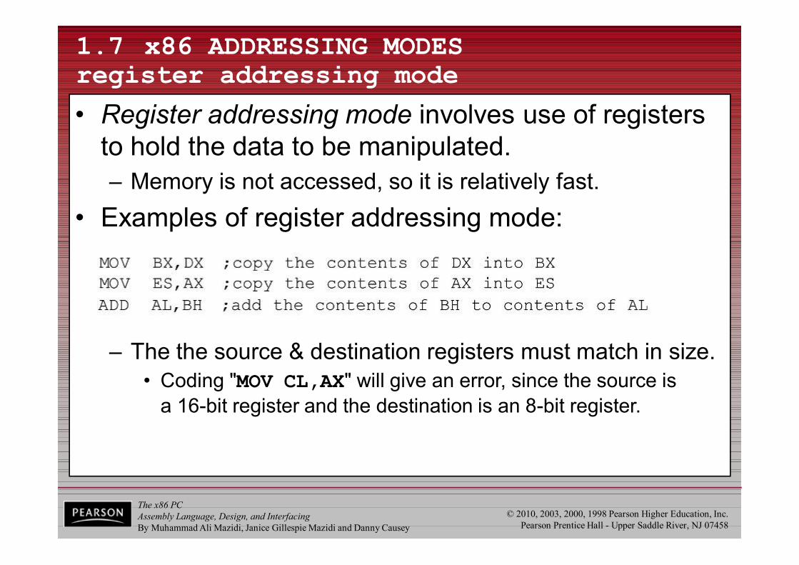
1.7 x86 ADDRESSING MODES register addressing mode
• Register addressing mode involves use of registers to hold the data to be manipulated.– Memory is not accessed, so it is relatively fast.
• Examples of register addressing mode:
– The the source & destination registers must match in size.• Coding "MOV CL,AX" will give an error, since the source is
a 16-bit register and the destination is an 8-bit register.
The x86 PCAssembly Language, Design, and InterfacingBy Muhammad Ali Mazidi, Janice Gillespie Mazidi and Danny Causey
© 2010, 2003, 2000, 1998 Pearson Higher Education, Inc.Pearson Prentice Hall - Upper Saddle River, NJ 07458
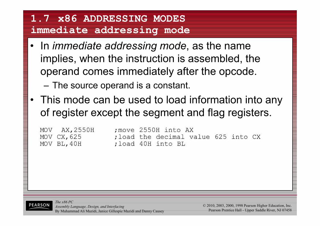
1.7 x86 ADDRESSING MODES immediate addressing mode
• In immediate addressing mode, as the name implies, when the instruction is assembled, the operand comes immediately after the opcode.– The source operand is a constant.
• This mode can be used to load information into any of register except the segment and flag registers.
The x86 PCAssembly Language, Design, and InterfacingBy Muhammad Ali Mazidi, Janice Gillespie Mazidi and Danny Causey
© 2010, 2003, 2000, 1998 Pearson Higher Education, Inc.Pearson Prentice Hall - Upper Saddle River, NJ 07458
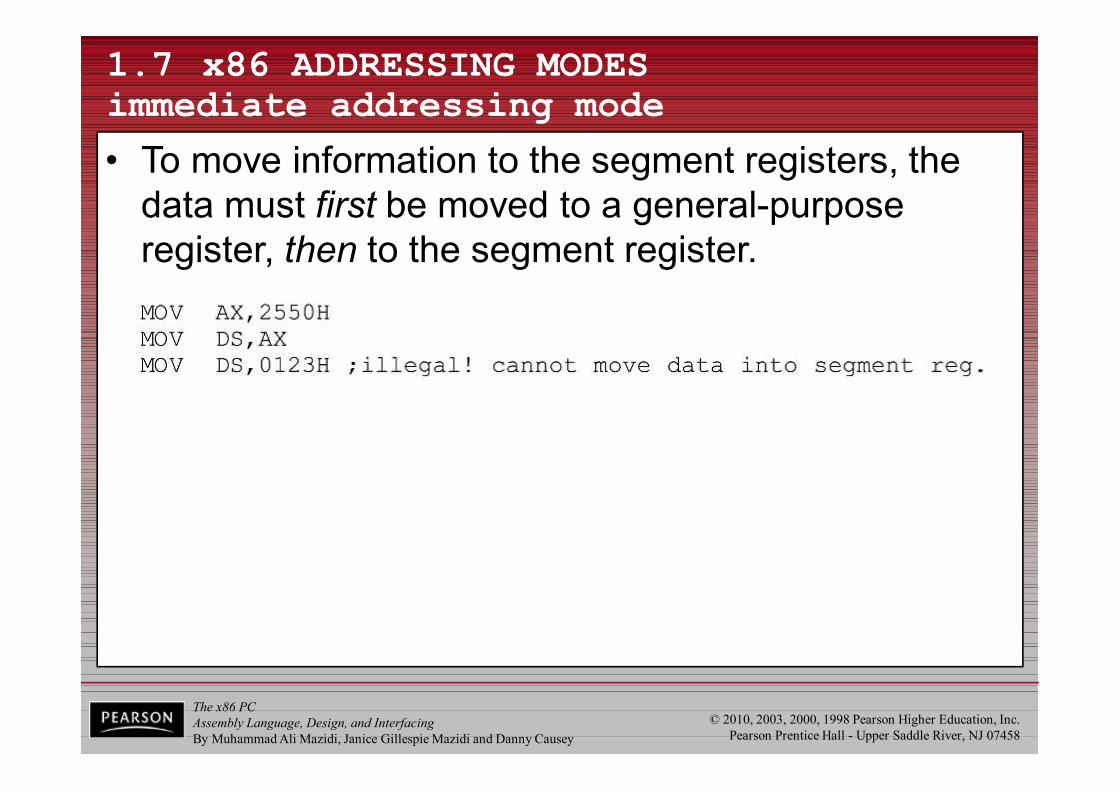
1.7 x86 ADDRESSING MODES immediate addressing mode
• To move information to the segment registers, the data must first be moved to a general-purpose register, then to the segment register.
The x86 PCAssembly Language, Design, and InterfacingBy Muhammad Ali Mazidi, Janice Gillespie Mazidi and Danny Causey
© 2010, 2003, 2000, 1998 Pearson Higher Education, Inc.Pearson Prentice Hall - Upper Saddle River, NJ 07458
1.7 x86 ADDRESSING MODES direct addressing mode
• In direct addressing mode, the data is in some memory location(s). – In most programs, the data to be processed is often
in some memory location outside the CPU.– The address of the data in memory comes immediately
after the instruction.
The x86 PCAssembly Language, Design, and InterfacingBy Muhammad Ali Mazidi, Janice Gillespie Mazidi and Danny Causey
© 2010, 2003, 2000, 1998 Pearson Higher Education, Inc.Pearson Prentice Hall - Upper Saddle River, NJ 07458
1.7 x86 ADDRESSING MODES direct addressing mode
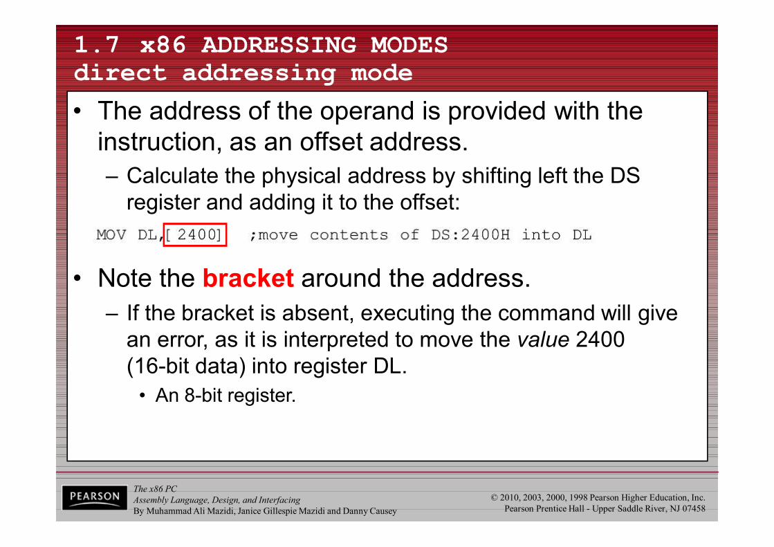
• The address of the operand is provided with the instruction, as an offset address.– Calculate the physical address by shifting left the DS
register and adding it to the offset:
• Note the bracket around the address.– If the bracket is absent, executing the command will give
an error, as it is interpreted to move the value 2400 (16-bit data) into register DL.
• An 8-bit register.
The x86 PCAssembly Language, Design, and InterfacingBy Muhammad Ali Mazidi, Janice Gillespie Mazidi and Danny Causey
© 2010, 2003, 2000, 1998 Pearson Higher Education, Inc.Pearson Prentice Hall - Upper Saddle River, NJ 07458117
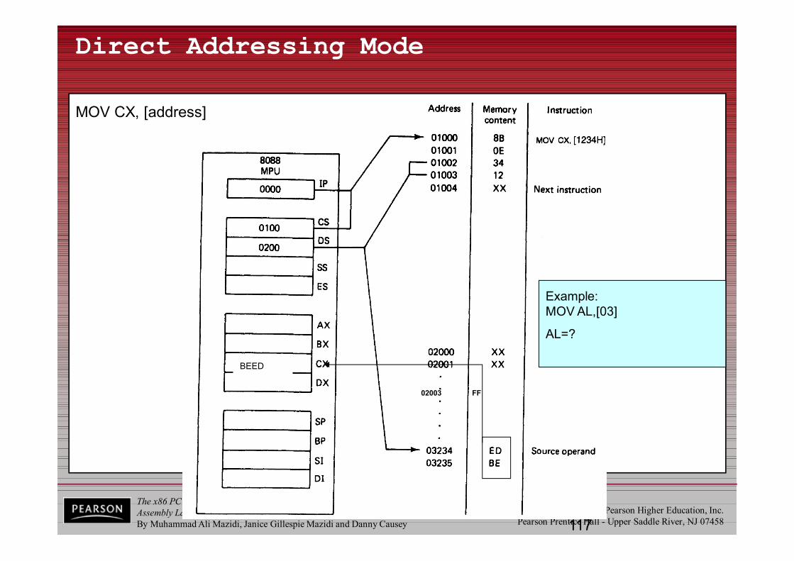
Direct Addressing Mode
02003 FF
Example:MOV AL,[03]
AL=?
MOV CX, [address]
BEED
The x86 PCAssembly Language, Design, and InterfacingBy Muhammad Ali Mazidi, Janice Gillespie Mazidi and Danny Causey
© 2010, 2003, 2000, 1998 Pearson Higher Education, Inc.Pearson Prentice Hall - Upper Saddle River, NJ 07458
1.7 x86 ADDRESSING MODES register indirect addressing mode
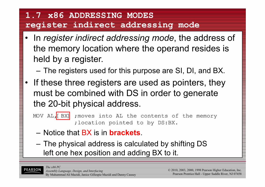
• In register indirect addressing mode, the address of the memory location where the operand resides is held by a register.– The registers used for this purpose are SI, DI, and BX.
• If these three registers are used as pointers, they must be combined with DS in order to generatethe 20-bit physical address.
– Notice that BX is in brackets.– The physical address is calculated by shifting DS
left one hex position and adding BX to it.

The x86 PCAssembly Language, Design, and InterfacingBy Muhammad Ali Mazidi, Janice Gillespie Mazidi and Danny Causey
© 2010, 2003, 2000, 1998 Pearson Higher Education, Inc.Pearson Prentice Hall - Upper Saddle River, NJ 07458
1.7 x86 ADDRESSING MODES register indirect addressing mode
• The same rules apply when using register SI or DI.
• Example 1-16 shows 16-bit data.
The x86 PCAssembly Language, Design, and InterfacingBy Muhammad Ali Mazidi, Janice Gillespie Mazidi and Danny Causey
© 2010, 2003, 2000, 1998 Pearson Higher Education, Inc.Pearson Prentice Hall - Upper Saddle River, NJ 07458120
Example for Register Indirect Addressing
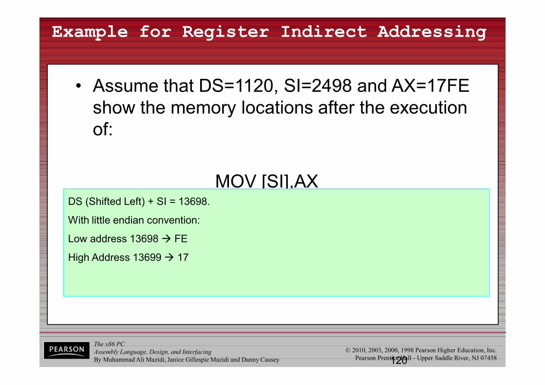
• Assume that DS=1120, SI=2498 and AX=17FE show the memory locations after the execution of:
MOV [SI],AXDS (Shifted Left) + SI = 13698.
With little endian convention:
Low address 13698 FE
High Address 13699 17

The x86 PCAssembly Language, Design, and InterfacingBy Muhammad Ali Mazidi, Janice Gillespie Mazidi and Danny Causey
© 2010, 2003, 2000, 1998 Pearson Higher Education, Inc.Pearson Prentice Hall - Upper Saddle River, NJ 07458121
Register Indirect Addressing Mode
MOV AX,
BXDISI
BEED
The x86 PCAssembly Language, Design, and InterfacingBy Muhammad Ali Mazidi, Janice Gillespie Mazidi and Danny Causey
© 2010, 2003, 2000, 1998 Pearson Higher Education, Inc.Pearson Prentice Hall - Upper Saddle River, NJ 07458
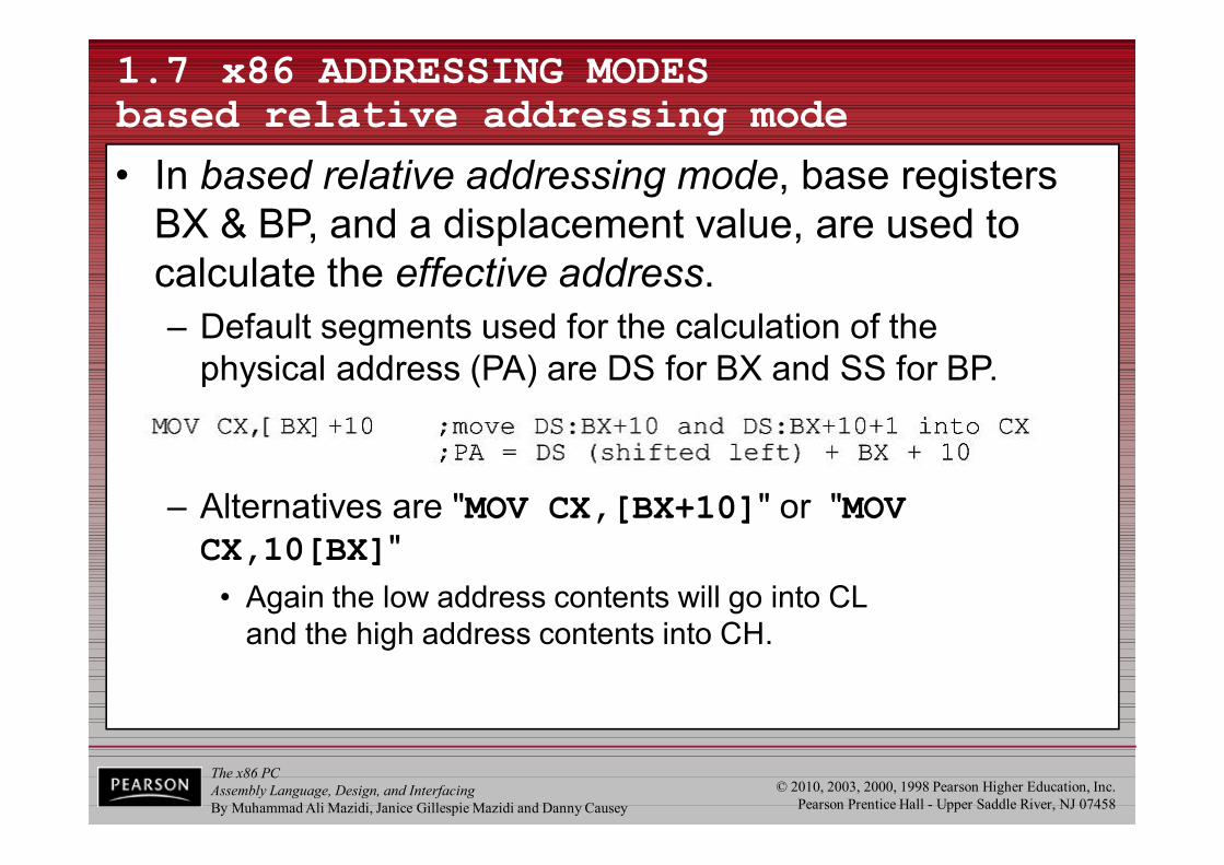
– Alternatives are "MOV CX,[BX+10]" or "MOV CX,10[BX]"
• Again the low address contents will go into CLand the high address contents into CH.
1.7 x86 ADDRESSING MODES based relative addressing mode
• In based relative addressing mode, base registers BX & BP, and a displacement value, are used to calculate the effective address.– Default segments used for the calculation of the
physical address (PA) are DS for BX and SS for BP.
The x86 PCAssembly Language, Design, and InterfacingBy Muhammad Ali Mazidi, Janice Gillespie Mazidi and Danny Causey
© 2010, 2003, 2000, 1998 Pearson Higher Education, Inc.Pearson Prentice Hall - Upper Saddle River, NJ 07458
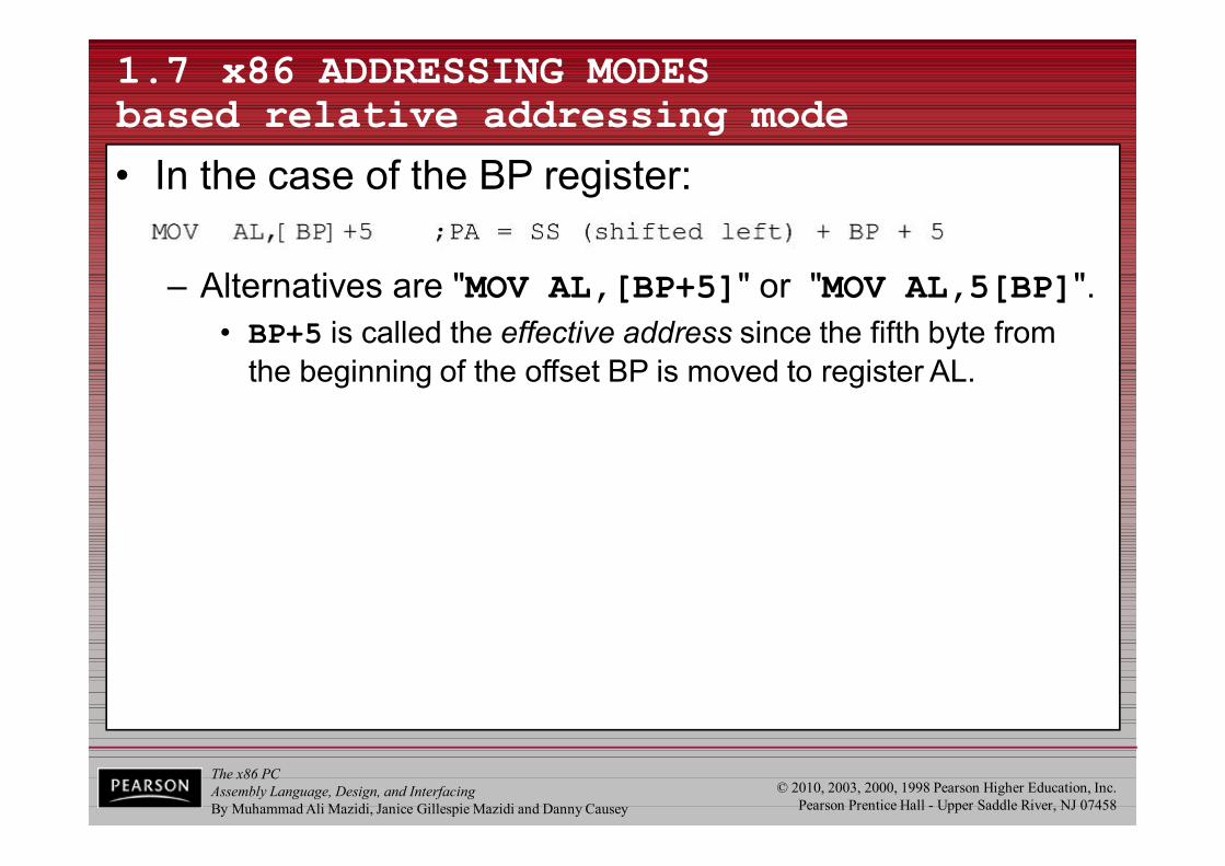
1.7 x86 ADDRESSING MODES based relative addressing mode
• In the case of the BP register:
– Alternatives are "MOV AL,[BP+5]" or "MOV AL,5[BP]".• BP+5 is called the effective address since the fifth byte from
the beginning of the offset BP is moved to register AL.

The x86 PCAssembly Language, Design, and InterfacingBy Muhammad Ali Mazidi, Janice Gillespie Mazidi and Danny Causey
© 2010, 2003, 2000, 1998 Pearson Higher Education, Inc.Pearson Prentice Hall - Upper Saddle River, NJ 07458124
Based-Relative Addressing Mode
MOV AH, [ ] + 1234hDS:BXSS:BP
AX
DS
BX
1234
3AH+

The x86 PCAssembly Language, Design, and InterfacingBy Muhammad Ali Mazidi, Janice Gillespie Mazidi and Danny Causey
© 2010, 2003, 2000, 1998 Pearson Higher Education, Inc.Pearson Prentice Hall - Upper Saddle River, NJ 07458
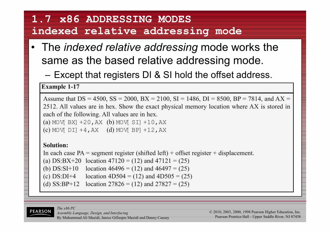
1.7 x86 ADDRESSING MODES indexed relative addressing mode
• The indexed relative addressing mode works the same as the based relative addressing mode.– Except that registers DI & SI hold the offset address.
The x86 PCAssembly Language, Design, and InterfacingBy Muhammad Ali Mazidi, Janice Gillespie Mazidi and Danny Causey
© 2010, 2003, 2000, 1998 Pearson Higher Education, Inc.Pearson Prentice Hall - Upper Saddle River, NJ 07458
1.7 x86 ADDRESSING MODES indexed relative addressing mode
• The indexed relative addressing mode works the same as the based relative addressing mode.– Except that registers DI & SI hold the offset address.
The x86 PCAssembly Language, Design, and InterfacingBy Muhammad Ali Mazidi, Janice Gillespie Mazidi and Danny Causey
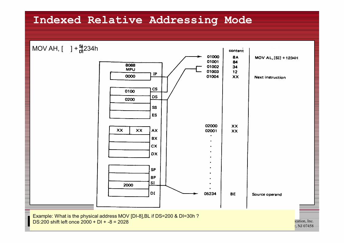
© 2010, 2003, 2000, 1998 Pearson Higher Education, Inc.Pearson Prentice Hall - Upper Saddle River, NJ 07458127
Indexed Relative Addressing Mode
MOV AH, [ ] + 1234hSIDI
Example: What is the physical address MOV [DI-8],BL if DS=200 & DI=30h ?DS:200 shift left once 2000 + DI + -8 = 2028
The x86 PCAssembly Language, Design, and InterfacingBy Muhammad Ali Mazidi, Janice Gillespie Mazidi and Danny Causey
© 2010, 2003, 2000, 1998 Pearson Higher Education, Inc.Pearson Prentice Hall - Upper Saddle River, NJ 07458
1.7 x86 ADDRESSING MODES based indexed addressing mode
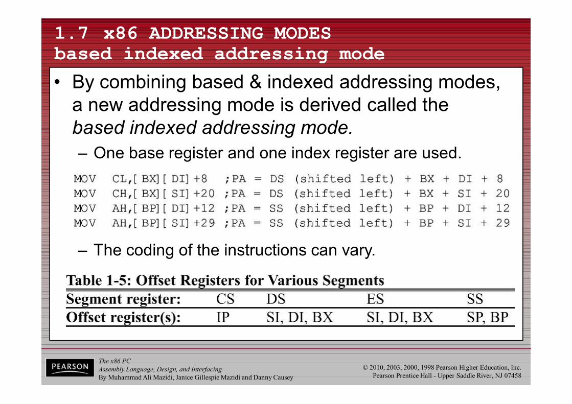
• By combining based & indexed addressing modes, a new addressing mode is derived called the based indexed addressing mode.
– The coding of the instructions can vary.
– One base register and one index register are used.

The x86 PCAssembly Language, Design, and InterfacingBy Muhammad Ali Mazidi, Janice Gillespie Mazidi and Danny Causey
© 2010, 2003, 2000, 1998 Pearson Higher Education, Inc.Pearson Prentice Hall - Upper Saddle River, NJ 07458129
Based-Indexed Addressing Mode
• Based Relative + Indexed Relative• We must calculate the PA (physical address)
CS
SS BX SI 8 bit displacementPA= DS : BP + DI + 16 bit displacement
ES
MOV AH,[BP+SI+29]orMOV AH,[SI+29+BP]orMOV AH,[SI][BP]+29
The register order does not matter

The x86 PCAssembly Language, Design, and InterfacingBy Muhammad Ali Mazidi, Janice Gillespie Mazidi and Danny Causey
© 2010, 2003, 2000, 1998 Pearson Higher Education, Inc.Pearson Prentice Hall - Upper Saddle River, NJ 07458130
Based-Indexed Addressing Mode
MOV BX, 0600hMOV SI, 0010h ; 4 records, 4 elements each.MOV AL, [BX + SI + 3]
OR
MOV BX, 0600hMOV AX, 004h ; MOV CX,04h; MUL CXMOV SI, AXMOV AL, [BX + SI + 3]
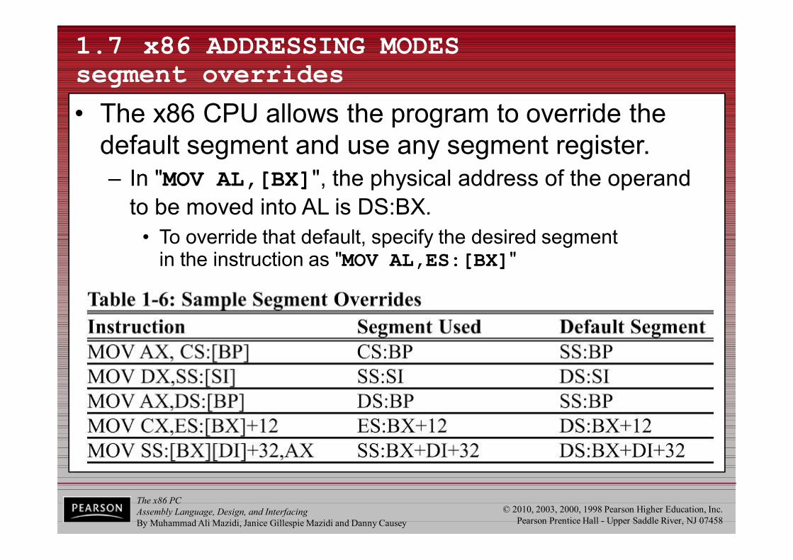
The x86 PCAssembly Language, Design, and InterfacingBy Muhammad Ali Mazidi, Janice Gillespie Mazidi and Danny Causey
© 2010, 2003, 2000, 1998 Pearson Higher Education, Inc.Pearson Prentice Hall - Upper Saddle River, NJ 07458
1.7 x86 ADDRESSING MODES segment overrides
• The x86 CPU allows the program to override the default segment and use any segment register.– In "MOV AL,[BX]", the physical address of the operand
to be moved into AL is DS:BX.• To override that default, specify the desired segment
in the instruction as "MOV AL,ES:[BX]"
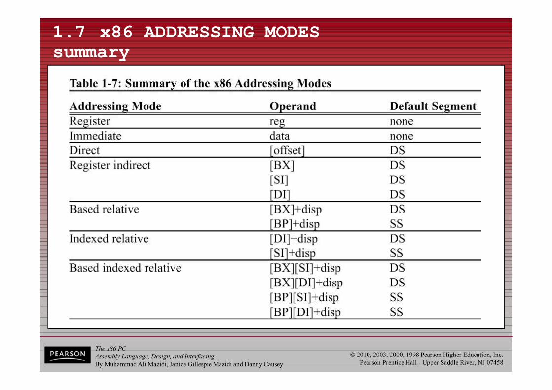
The x86 PCAssembly Language, Design, and InterfacingBy Muhammad Ali Mazidi, Janice Gillespie Mazidi and Danny Causey
© 2010, 2003, 2000, 1998 Pearson Higher Education, Inc.Pearson Prentice Hall - Upper Saddle River, NJ 07458
1.7 x86 ADDRESSING MODESsummary

The x86 PCAssembly Language, Design, and InterfacingBy Muhammad Ali Mazidi, Janice Gillespie Mazidi and Danny Causey
© 2010, 2003, 2000, 1998 Pearson Higher Education, Inc.Pearson Prentice Hall - Upper Saddle River, NJ 07458
1.5 THE STACK what is a stack? why is it needed?
• The stack is a section of read/write memory (RAM) used by the CPU to store information temporarily.– The CPU needs this storage area since there are
only a limited number of registers.• There must be some place for the CPU to store
information safely and temporarily.
• The main disadvantage of the stack is access time.– Since the stack is in RAM, it takes much longer to
access compared to the access time of registers.• Some very powerful (expensive) computers do not
have a stack.– The CPU has a large number of registers to work with.
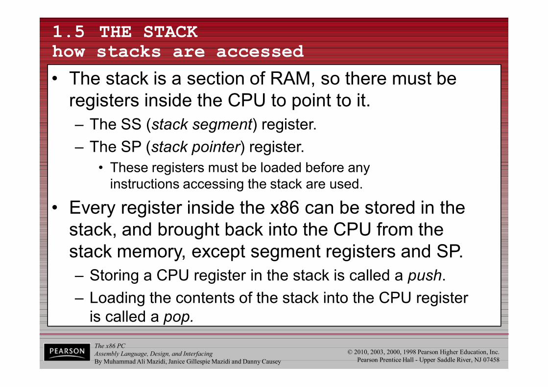
The x86 PCAssembly Language, Design, and InterfacingBy Muhammad Ali Mazidi, Janice Gillespie Mazidi and Danny Causey
© 2010, 2003, 2000, 1998 Pearson Higher Education, Inc.Pearson Prentice Hall - Upper Saddle River, NJ 07458
1.5 THE STACK how stacks are accessed
• The stack is a section of RAM, so there must be registers inside the CPU to point to it.– The SS (stack segment) register.– The SP (stack pointer) register.
• These registers must be loaded before anyinstructions accessing the stack are used.
• Every register inside the x86 can be stored in the stack, and brought back into the CPU from thestack memory, except segment registers and SP.– Storing a CPU register in the stack is called a push.– Loading the contents of the stack into the CPU register
is called a pop.

The x86 PCAssembly Language, Design, and InterfacingBy Muhammad Ali Mazidi, Janice Gillespie Mazidi and Danny Causey
© 2010, 2003, 2000, 1998 Pearson Higher Education, Inc.Pearson Prentice Hall - Upper Saddle River, NJ 07458
1.5 THE STACK how stacks are accessed
• The x86 stack pointer register (SP) points at the current memory location used as the top of the stack.– As data is pushed onto the stack it is decremented.– As data is popped off the stack into the CPU, it is incremented.
• When an instruction pushes or pops a general-purpose register, it must be the entire 16-bit register.– One must code "PUSH AX".
• There are no instructions such as "PUSH AL" or "PUSH AH".
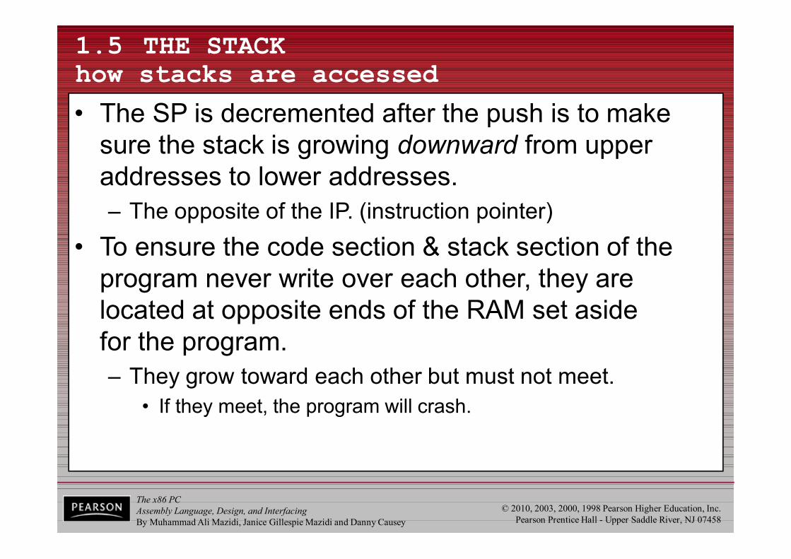
The x86 PCAssembly Language, Design, and InterfacingBy Muhammad Ali Mazidi, Janice Gillespie Mazidi and Danny Causey
© 2010, 2003, 2000, 1998 Pearson Higher Education, Inc.Pearson Prentice Hall - Upper Saddle River, NJ 07458
1.5 THE STACK how stacks are accessed
• The SP is decremented after the push is to make sure the stack is growing downward from upper addresses to lower addresses.– The opposite of the IP. (instruction pointer)
• To ensure the code section & stack section of the program never write over each other, they arelocated at opposite ends of the RAM set asidefor the program.– They grow toward each other but must not meet.
• If they meet, the program will crash.
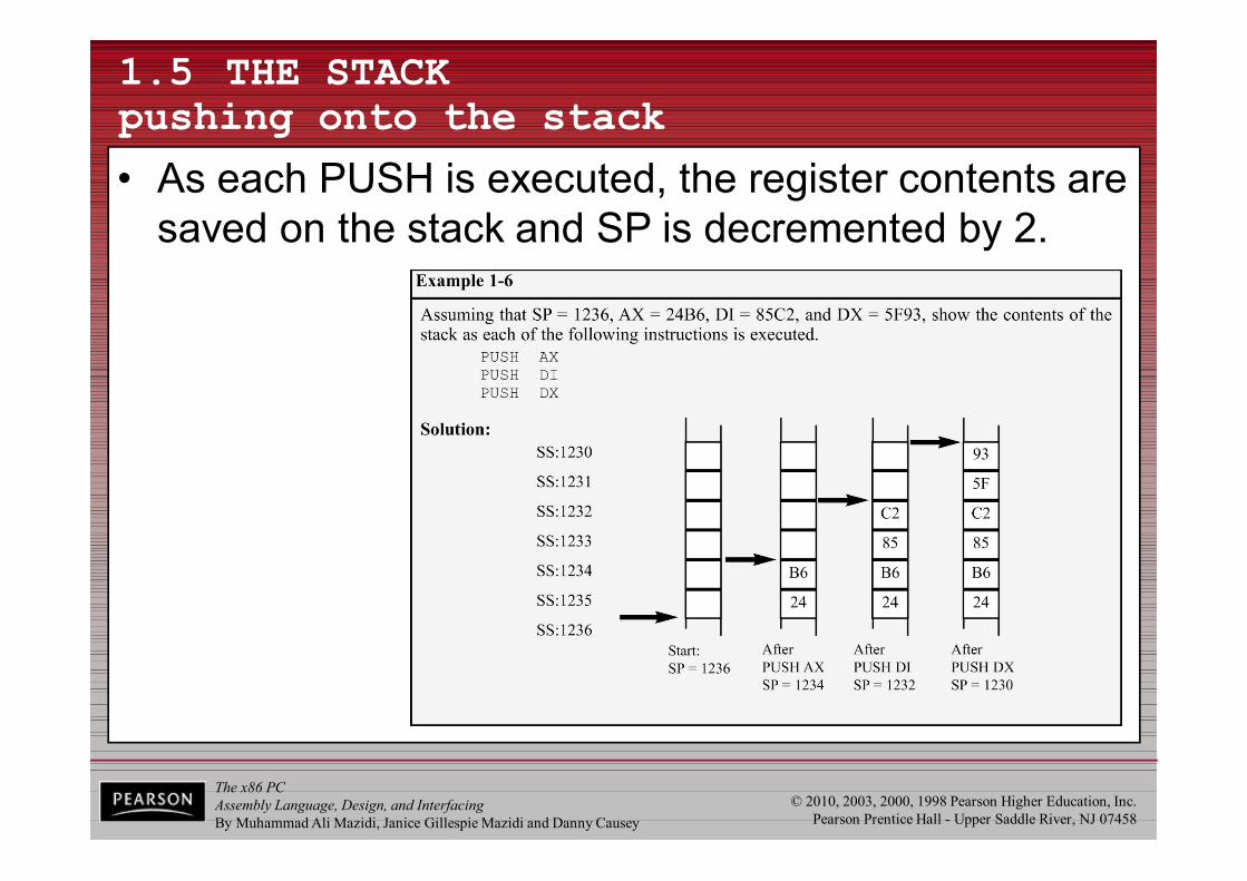
The x86 PCAssembly Language, Design, and InterfacingBy Muhammad Ali Mazidi, Janice Gillespie Mazidi and Danny Causey
© 2010, 2003, 2000, 1998 Pearson Higher Education, Inc.Pearson Prentice Hall - Upper Saddle River, NJ 07458
1.5 THE STACK pushing onto the stack
• As each PUSH is executed, the register contents are saved on the stack and SP is decremented by 2.
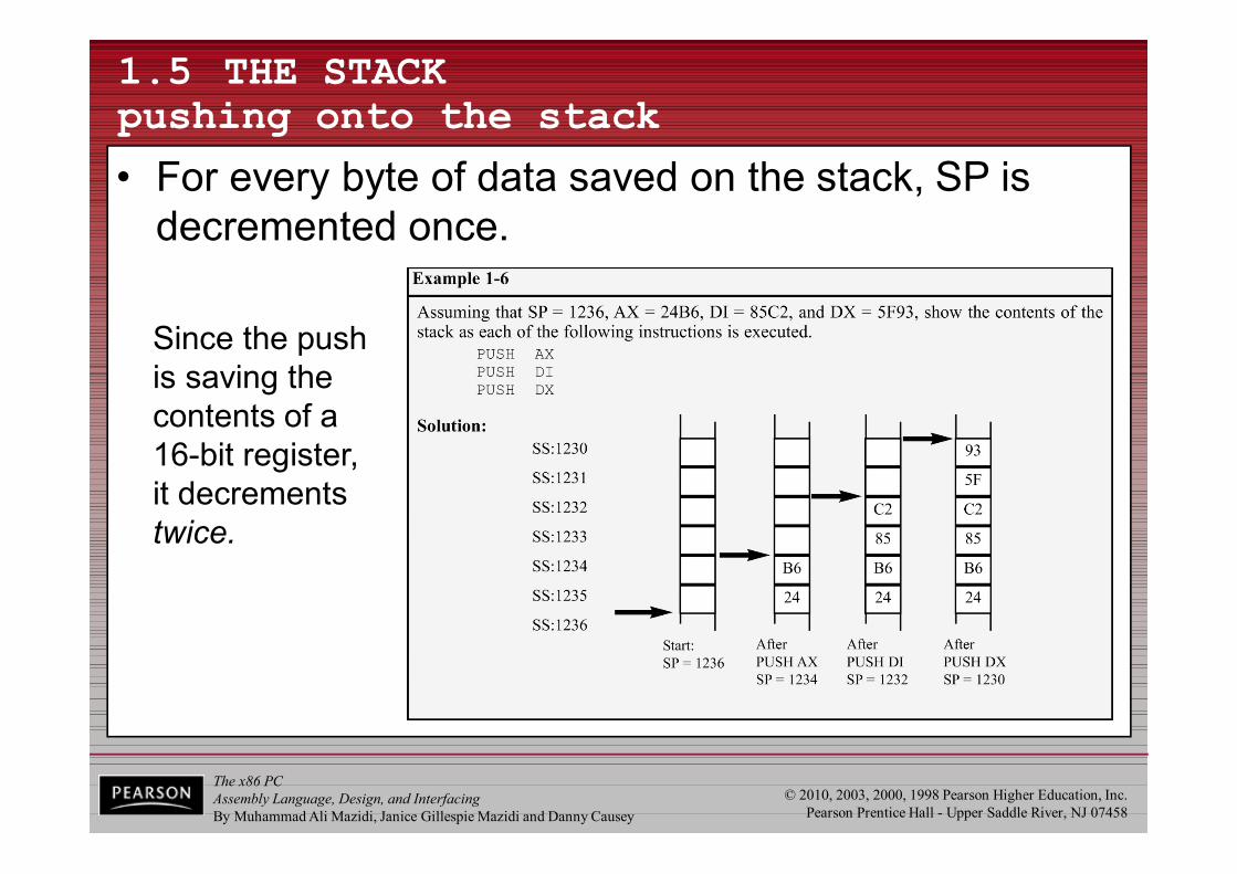
The x86 PCAssembly Language, Design, and InterfacingBy Muhammad Ali Mazidi, Janice Gillespie Mazidi and Danny Causey
© 2010, 2003, 2000, 1998 Pearson Higher Education, Inc.Pearson Prentice Hall - Upper Saddle River, NJ 07458
1.5 THE STACK pushing onto the stack
• For every byte of data saved on the stack, SP is decremented once.
Since the pushis saving the contents of a16-bit register,it decrements twice.
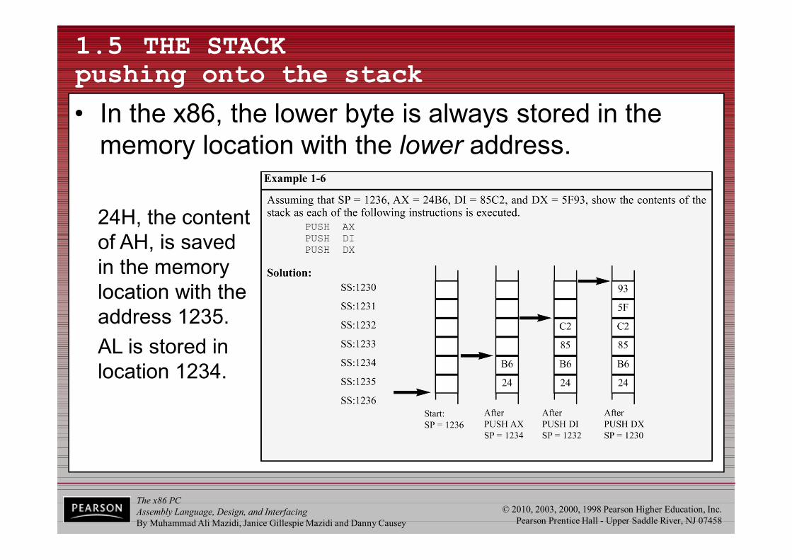
The x86 PCAssembly Language, Design, and InterfacingBy Muhammad Ali Mazidi, Janice Gillespie Mazidi and Danny Causey
© 2010, 2003, 2000, 1998 Pearson Higher Education, Inc.Pearson Prentice Hall - Upper Saddle River, NJ 07458
1.5 THE STACK pushing onto the stack
• In the x86, the lower byte is always stored in the memory location with the lower address.
24H, the content of AH, is savedin the memory location with the address 1235.AL is stored in location 1234.
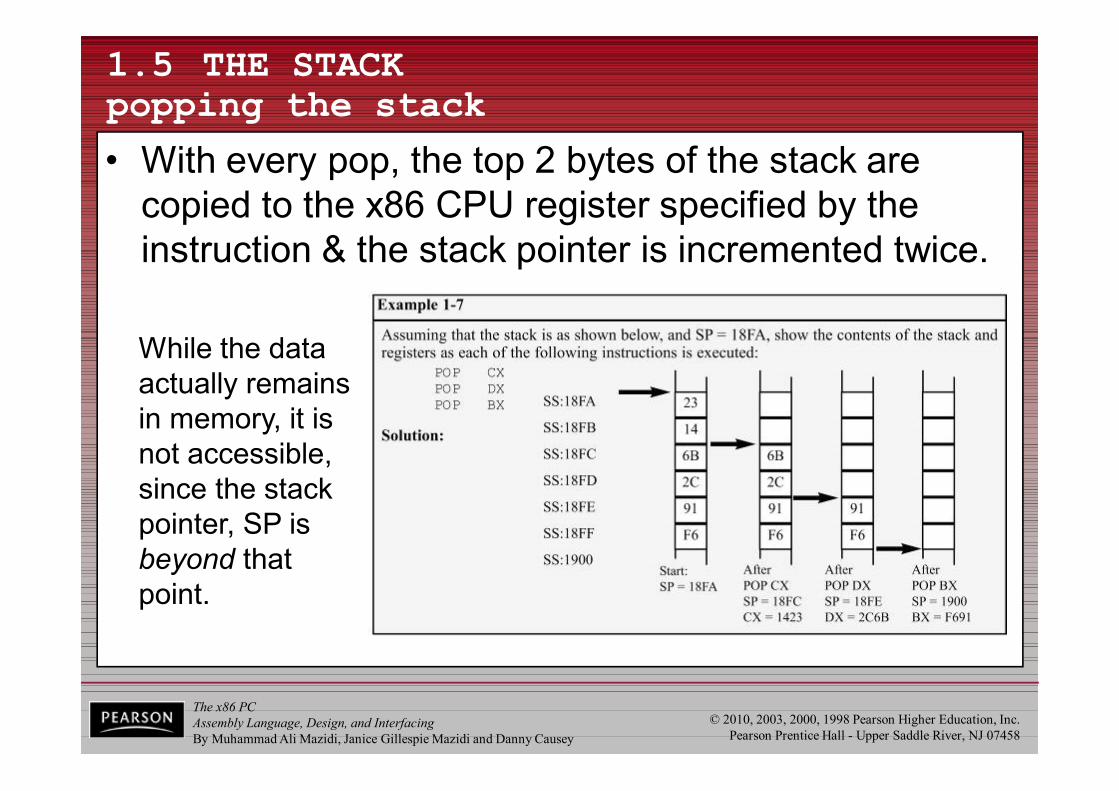
The x86 PCAssembly Language, Design, and InterfacingBy Muhammad Ali Mazidi, Janice Gillespie Mazidi and Danny Causey
© 2010, 2003, 2000, 1998 Pearson Higher Education, Inc.Pearson Prentice Hall - Upper Saddle River, NJ 07458
1.5 THE STACK popping the stack
• With every pop, the top 2 bytes of the stack are copied to the x86 CPU register specified by the instruction & the stack pointer is incremented twice.
While the data actually remains in memory, it is not accessible, since the stack pointer, SP is beyond that point.
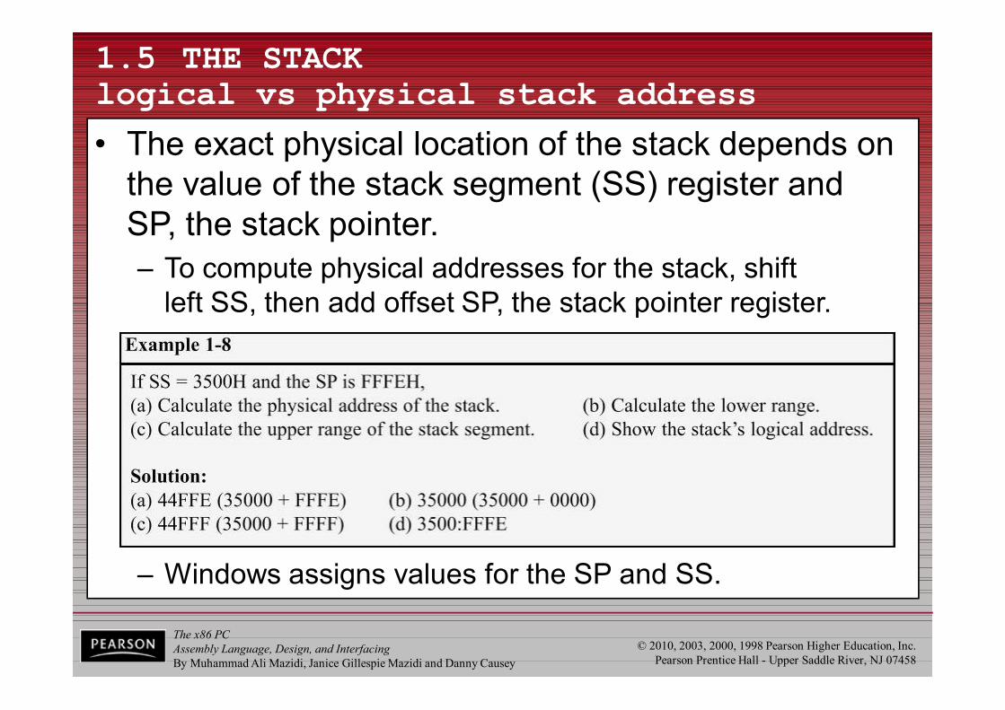
The x86 PCAssembly Language, Design, and InterfacingBy Muhammad Ali Mazidi, Janice Gillespie Mazidi and Danny Causey
© 2010, 2003, 2000, 1998 Pearson Higher Education, Inc.Pearson Prentice Hall - Upper Saddle River, NJ 07458
1.5 THE STACK logical vs physical stack address
• The exact physical location of the stack depends on the value of the stack segment (SS) register andSP, the stack pointer.– To compute physical addresses for the stack, shift
left SS, then add offset SP, the stack pointer register.
– Windows assigns values for the SP and SS.
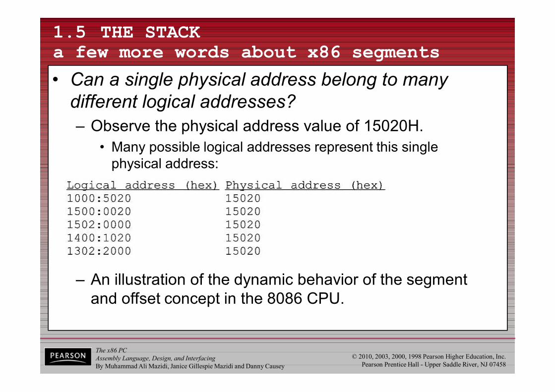
The x86 PCAssembly Language, Design, and InterfacingBy Muhammad Ali Mazidi, Janice Gillespie Mazidi and Danny Causey
© 2010, 2003, 2000, 1998 Pearson Higher Education, Inc.Pearson Prentice Hall - Upper Saddle River, NJ 07458
1.5 THE STACKa few more words about x86 segments
• Can a single physical address belong to many different logical addresses? – Observe the physical address value of 15020H.
• Many possible logical addresses represent this singlephysical address:
– An illustration of the dynamic behavior of the segment and offset concept in the 8086 CPU.
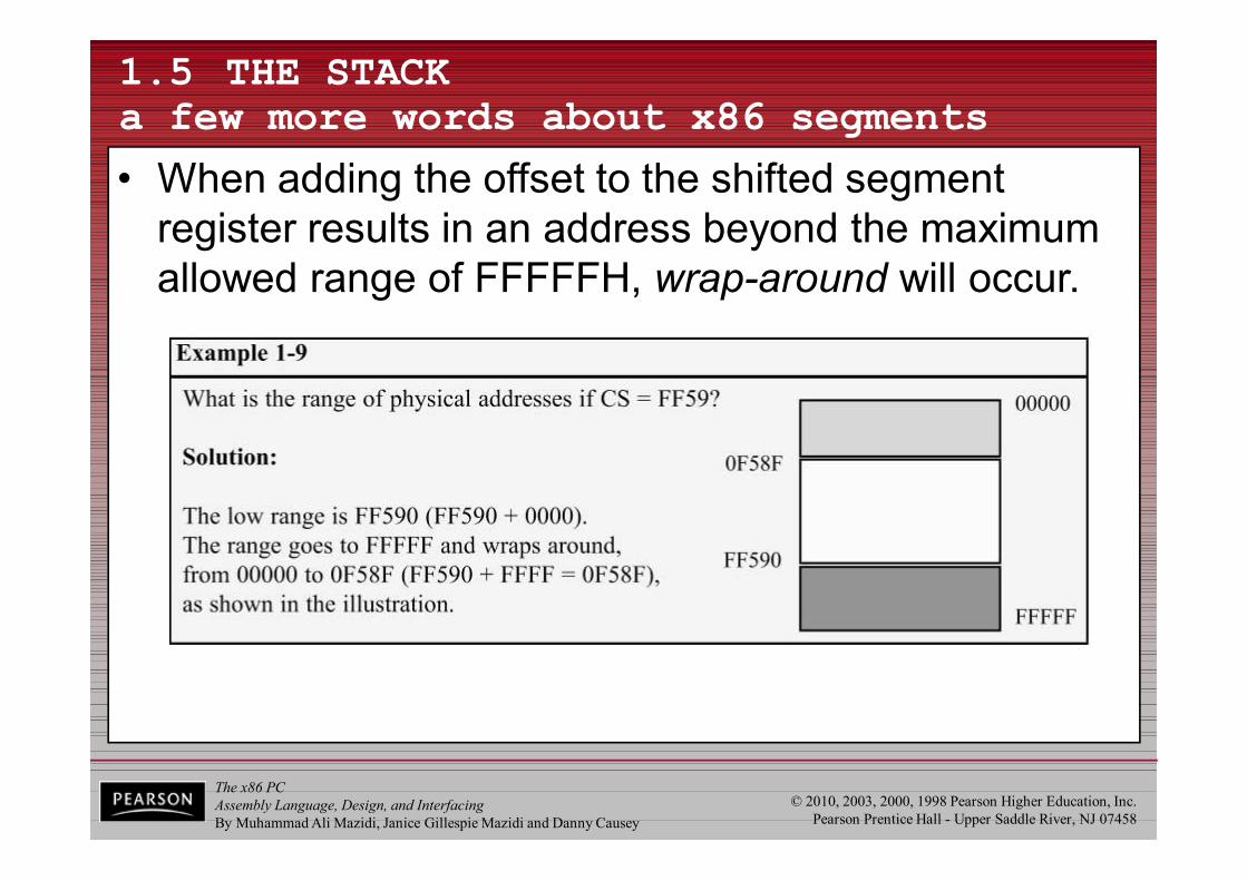
The x86 PCAssembly Language, Design, and InterfacingBy Muhammad Ali Mazidi, Janice Gillespie Mazidi and Danny Causey
© 2010, 2003, 2000, 1998 Pearson Higher Education, Inc.Pearson Prentice Hall - Upper Saddle River, NJ 07458
1.5 THE STACKa few more words about x86 segments
• When adding the offset to the shifted segment register results in an address beyond the maximum allowed range of FFFFFH, wrap-around will occur.
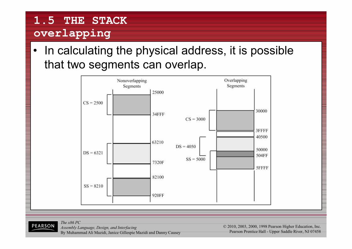
The x86 PCAssembly Language, Design, and InterfacingBy Muhammad Ali Mazidi, Janice Gillespie Mazidi and Danny Causey
© 2010, 2003, 2000, 1998 Pearson Higher Education, Inc.Pearson Prentice Hall - Upper Saddle River, NJ 07458
1.5 THE STACKoverlapping
• In calculating the physical address, it is possible that two segments can overlap.

The x86 PCAssembly Language, Design, and InterfacingBy Muhammad Ali Mazidi, Janice Gillespie Mazidi and Danny Causey
© 2010, 2003, 2000, 1998 Pearson Higher Education, Inc.Pearson Prentice Hall - Upper Saddle River, NJ 07458
ENDS ; ONEDec Hex Bin1 1 00000001