the universal software for 3d-metrology, reverse engineering and surveying
TRANSCRIPT

The Universal Software for 3D-metrology, Reverse Engineering and Surveying
InnovMetric Software Inc.
Québec, Canada
www.innovmetric.com
Detroit, USA
Los Angeles, USA
Salisbury (North Carolina), USA
Shanghai, China
Pune, Indien
Duwe-3d AG
Peter-Dornier-Straße 9
88131 Lindau (B), Germany
T +49 (0)8382 27590-0
F +49 (0)8382 27590-29
www.duwe-3d.de
Duwe-3d AG (France)
5 rue des Frères Lumière
78370 Plaisir, France
www.duwe-3d.eu
PolyWorks® ist is a registered trademark
of InnovMetric Software Inc., Québec, Kanada.
www.innovmetric.com

02
The future of metrology depends on the complete and highly accurate aquisition of surfaces. In addition to single point measu-rements PolyWorks improves the analysis and inspection of entire surface models. This encorporates the whole process from capturing point clouds to processing and modelling surfaces.
As a universal software platform PolyWorks integrates a wide range of optical and tactile 3D- digitizers. Whether in design, quality assurance or surveying: The application range of the software in combination with 3D-measuring devices is almost unlimited.
PolyWorks is being developed by the Canadi-an company InnovMetric Inc. Due to the large customer focus in the development process over the last 15 years, PolyWorks has proven itself in countless industries. In the automotive and aeronautic business Poly-Works has become the standard point cloud engineering software solution worldwide. As the european partner of InnovMet-ric Software Inc. Duwe-3d supports the numerous PolyWorks users and sensor manufacturers throughout Europe. We offer consulting on the introduction of new mea-surement strategies with PolyWorks and provide individual training and professional support.
What is PolyWorks®?PolyWorks is the universal 3D Metrology Software Platform for proces-
sing and analyzing three-dimensional datasets.

0403
Measurement Plan and Specifications
Measurement Result and Report
PolyWorks implements direct interfaces for all
tactile and optical digitizers.
R 30
05
The application range of PolyWorks in combination with
modern 3d-digitizing devices is almost unlimited.

D 29,7
z
y
x
Interactive PositioningEven the positioning of physical components can be conducted with the help of PolyWorks. In build-inspect mode the 3-dimensional distance of a part to its target position is calculated in realtime . The deviation can then be displayed graphically or numerically. In combination with point based devices, such as laser trackers, PolyWorks will allow you to precisely position machines, fixtures and tools for assembly.
06 07
Virtual Assembly
On the basis of such a dataset PolyWorks can perform all sorts of measurements, non-destructive and repeatable. The soft-ware extracts regular shapes, such as circles, lines, planes or cylinders from point clouds and determines relevant dimensions such as length, width, height and angle. Features can also be probed directly with the help of tactile digitizing devices.
By combining existing entities PolyWorks allows you to create totally new geometries while storing their relationships to other objects. This creates a whole set of new opportunities for dimensional verification.
PolyWorks can quickly analyze the accuracy-of-fit of components of an assembly unit. For this purpose the software aligns the 3-dimensional datasets and simulates the ability to incorporate components in production before the actual assembly.
Measurements in three dimensionsBy digitizing surfaces with high-density point cloud digitizers, the full
geometrical shape of a part can be virtually captured and saved.
The evaluation tools in PolyWorks are:•Collisiondetectionandanalysis•Analysisofproblematicintersections•Analysisofdistancebetweencomponents

RPS1 Hxy Fz
RPS2 Hy
RPS3 Fz
RPS4 Fz
08 09
The result of the comparison is closely dependent on the chosen alignment strategy. PolyWorks supports a variety of alignment options and techniques, and thus adapts to the requirements of your measurement task.
All supported alignment strategies can be more closely specified by applying additional constraints.
The results of the comparison of surfaces can, for example, be visualized in customizable color maps, allowing the identification of areal deviations at a glance. A pass-fail analysis can be conducted by specifying local surface tolerances. For a detailed analysis PolyWorks also derives single comparison points from the surface or analyzes whole cross-sections in detail.
In addition PolyWorks enables you to compare all kinds of geometries like circles, cylindres or planes to their respective reference. The measured geometries are automatically assigned to the matching geometries in the CAD-Reference and evaluated in all relevant dimensions.
Alignment ComparisonIn order to compare three-dimensional datasets they need to be aligned
to each other and transfered into a common coordinate system.
PolyWorks allows you to compare measured datasets to CAD
surfaces or a second measured reference.
•Best-Fit-Alignment PolyWorks calculates the fit with the smallest total deviation (least-squares ap proximation). Existing tolerance zones are considered when required •3-2-1-Alignment Gradual reduction of the degrees of free- dom by aligning features like planes, vectors and points•Alignmentbasedonagivenreference point system (RPS), common in sheet metal inspection •Datumreferenceframealignment accordingtoGD&Tspecifications (DIN ISO 1101 and ASME Y14.5M)•OptimizedFlush&GapGaugesalignment•Variablealignmentsusingn-pairsof centerpoints •Manualalignments

.01
ø .05
10 11
Statistical Process ControlPolyWorks offers an embedded statistical process control (SPC) to
quickly analyze multiple digitized instances of a part or product.
The uniform symbolic GD&T language describes the functional properties and dimensions of parts and assemblies in detail. PolyWorks/Inspector™ contains a com-plete set of analysis tools for geometric dimensioning and tolerancing standards. In collaboration with Multi Metrics Inc., the
SmartGD&T™ technology was implemen-ted. This permits the uniform encoding and decoding of GD&T descriptions according to the standards ISO 1101 and ASME Y 14.5M directly in PolyWorks.
PolyWorks permits:•Thecreationandevaluationofdatums between points, lines and planes •Considerationofmaximum/minimum material conditions•Automaticextractionofrelatedfeatures•Analysisofsurfaceprofiletolerances•Datumbasedalignment
Geometric Dimensioning and TolerancingTolerancespecificationsintechnicaldrawingsareincreasinglybeing
replaced by modern GD&T standards.
During multi-piece inspection tasks the measurement data of multiple parts can easily be compared to each other or to CAD. Statistical parameters such as variance of point clouds or polygonal meshes can be displayed in a deviation color map. This colorful 3D visualization in PolyWorks is ideally suited to control and optimize pro-duction processes as it monitors changes in the production quality.
Range of functions:•Importofsinglemeasurements •Statisticalanalysisofsurfacepoints,cross sections, geometries, distances and other measuresaswellasflush&gapanalysis
•Generationofanaveragedpolygonal mesh on the basis of all digitized parts (golden template)•Colormaprepresentationoftheaverage andmaximumerror,thestandard deviation and the RMS-Error •Calculationofprocesscapabilityratios (Cp- and Cpk)•Trendanalysisandreporting functionalities

Airfoil, Profile & Radius Gauges
12 13
Aircraft wings, turbine blades, ship propellers, wind turbines and other
hydro-andaerodynamiccomponentsaredescribedbyacharacteristicprofile.
PolyWorks uses freely defineable cross-sections in order to derive geometric para-meters and to describe and evaluate these profiles.
•Extractionof"Camber-Line", "Stagger-Line","Leading-"and "Trailing-Edge"•Extractionofmanyotherrelevantpara- meters and radii•Implementationofthespecialalignment requirementsforaerodynamicprofiles •Advanced2Drepresentationofthe results •Possibilityforautomationofrepetitive measurements
Flush & Gap Analysis
In the automotive industry the transitions between doors and side frames for example are qualified by the Gap, i.e. the distance, and the Flush, i.e. the offset. Narrow gap dimensions optimize the aerodynamic characteristis of a vehicle, reduce driving noises and attest high quality of workmanship. Traditionally Flush and Gap were measured with simple mechanical caliper gauges and analysed locally. By digitizing with optical systems however, the complete profile of a gap transition can be derived in PolyWorks. This allows you to analyse the flush & gap at any number of positions simultaneously.
Range of functions:•Determinationofdistances,radiiaswell asradiusentryandexitpoints.•Classificationofcharacteristicradius curves•Customizationonthebasisoftemplates•Assessmentofotherdistinctivedesign elements and character lines (e.g. tornado line)
Where parts are joined in a functional way, the detailed analysis of
Flushes and Gaps gains more and more importance.
D3D++Nominal objects
Measured & nominal objects
1
2
6
3 4
5
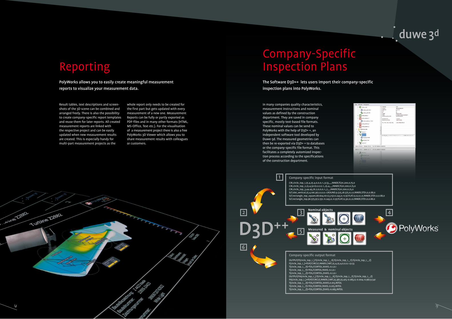
Company-SpecificInspection Plans
14 15
TheSoftwareD3D++letsusersimporttheircompany-specific
inspection plans into PolyWorks.
In many companies quality characteristics, measurement instructions and nominal values as defined by the construction department. They are saved in company specific, mostly text-based file formats. These nominal values can be send to PolyWorks with the help of D3D+ +, an independent software tool developed by Duwe-3d. The measured geometries can then be re-exported via D3D+ + to databases or the company-specific file format. This facilitates a completely automized inspec-tion process according to the specifications of the construction department.
Reporting
Result tables, text descriptions and screen- shots of the 3D scene can be combined and arranged freely. There is also the possibility to create company-specific report templates and reuse them for later reports. All created measurement reports are linked with the respective project and can be easily updated when new measurement results are created. This is especially handy for multi-part measurement projects as the
PolyWorks allows you to easily create meaningful measurement
reports to visualize your measurement data.
whole report only needs to be created for the first part but gets updated with every measurement of a new one. Measurement Reports can be fully or partly exported as PDF-files and in many other formats (HTML, MS-Office, Text etc.). For the visualisation of a measurement project there is also a free PolyWorks 3D Viewer which allows you to share measurement results with colleagues or customers.
Company specific input format
CIR,circle_top_1,25.4,25.4,0,0,0,-1,,9.53,,,,,INNER,TG01,200,0.75,0CIR,circle_top_2,25.4,50.8,0,0,0,-1,,25.4,,,,,INNER,TG01,200,0.75,0CIR,circle_top_3,44.45,76.2,0,0,0,-1,,7,,,,,INNER,TG01,200,0.75,0SLT,slot_vertical,25.4,106.362,0,0,0,-1,ROUND,9.525,28.575,0,1,0,INNER,STD1,0,0.88,0SLT,rectangle_top_square,68.604,101.6,3.157,0.243,0,-0.97,FLAT,12,12,0,1,0,INNER,STD1,0,0.88,0SLT,rectangle_top,96.573,97,2.551,-0.243,0,-0.97,FLAT,12,30,0,1,0,INNER,STD1,0,0.88,0
Company specific output format
OUTPUT/F(circle_top_1_),T(circle_top_1__X),T(circle_top_1__Y),T(circle_top_1__Z)F(circle_top_1_)=FEAT/CIRCLE,INNER,CART,25.4,25.4,0,0,0,-1,9.53T(circle_top_1__X)=TOL/CORTOL,XAXIS,-0.1,0.1T(circle_top_1__Y)=TOL/CORTOL,YAXIS,-0.1,0.1T(circle_top_1__Z)=TOL/CORTOL,ZAXIS,-0.1,0.1OUTPUT/FA(circle_top_1_),T(circle_top_1__X),T(circle_top_1__Y),T(circle_top_1__Z)FA(circle_top_1_)=FEAT/CIRCLE,INNER,CART,25.387,25.415,-0.083,0,-0.004,-0.987,9.541T(circle_top_1__X)=TOL/CORTOL,XAXIS,0.013,INTOLT(circle_top_1__Y)=TOL/CORTOL,YAXIS,-0.015,INTOLT(circle_top_1__Z)=TOL/CORTOL,ZAXIS,-0.083,INTOL

16 17
From Point Clouds to Polygonal Meshes
Polygonal Meshes: Smoothing and Filtering
In order to use the recorded data for visu-alization, simulation, rapid prototyping or for milling, these point clouds have to be converted into a polygonal model. PolyWorks supports the entire process of data acquisition and processing through a comprehensive set of functionalities. The software lets you create polygonal meshes
by connecting the single points of a point cloud. This process is called triangulation. A single virtual object surface (topology) is formed. PolyWorks always tries to generate triangle meshes with a hexagonal structure whenever possible. The resulting meshes can be saved in STL format for further use.
•Best-Fit-alignmentofscandataand overlapping point clouds•Noisefilterandreductionofpointclouds •Quickgenerationofpolygonalmeshes with adjustable resolution and accuracy, even with large amounts of data.
With the help of optical digitizing devices models or parts can be digi-
tized as 3D point clouds for various applications, such as design, mold
making and tooling,
PolyWorksoffersarangeofcustomizableandflexiblefunctionsthatlet
youprocessandoptimizeexistingpolygonalsurfacemodels.
The software offers a tolerance-based re-duction of the number of triangles in order to reduce the file size and accelerate further processing steps. Multiple meshes can also be combined and merged into a single polygonal mesh. Even converting imported CAD data into watertight meshes is a fast and easy process in PolyWorks. Futhermore the triangle topolgy can be optimized and polygonal meshes can be smoothed and filtered as required.
PolyWorks allows you to modify the size and structure of a polygonal mesh for: •High-speedmilling•Aerodynamicsimulation(CFD)
•Rapidprototyping•Visualisation

18 19
Advanced Modeling Reverse Engineering
Weather you need to correct the topology, close holes with one of the numerous algo-rithms or rebuild specific areas completely: PolyWorks offers automatic and interactive methods that get the job done. By fitting curves into the polygonal mesh, boundaries
can be trimmed and reconstructed. PolyWorks detects round corners and feature lines of parts automatically and reconstructs them as sharp edges. In addition geometric shapes such as cylinders or circles can be fitted into the polygonal mesh and surfaces can be modeled freely. With boolean operations it is furthermore possible to combine and intersect existing polygonal models.
Additional features:•Extractionofcurvesandcharacterlines•Modificationandoptimizationofcurves•Morphingfunctionalitiestoupdate existingCADdata•Creationofregular„Quad-Mesh"- structuresfromexistingtrianglemeshes, e.g. for FEM simulation (NASTRAN-format)
The possibilities for editing meshes in PolyWorks are almost unlimited. Polygonal meshes cannot directly be used for construction and design in
CAD software as they lack parametric information. Therefore, a further pro-
cessing step is necessary in order to use digitized datasets in modern CAD
applications.
PolyWorks can transfer the polygonal mesh structure into regular geometries and freeform surfaces. By using spline curve networks,NURBSpatchesarefittedontoanexistingpolygonalmesh.Theadjustmentof the surfaces can be varied to compensate for local inaccuracies in the original data. ThefittedNURBSsurfacescanbeexportedas a CAD model. In addition Polyworks letsyouupdateandcorrectexistingCADmodels.
•SupportforG1andG2continuitybetween surfaces•ExporttoCADsystemsinIGESandSTEP format

21
Precision – this is what we put in everything we do. In our core business, the distribution and support of PolyWorks that means providing our customers with individual solutions and measurement strategies with PolyWorks. But no matter where PolyWorks is in use: Thanks to the revolutionary technology the applications of the software are almost unlimited. PolyWorks is always the first choice for processing and inspecting three-dimensional data sets.
We are glad that our customers feel the same.
Our Customers:
ABB
Airbus
Audi
BASF
Benteler
BMW
Bosch
Continental
Daimler
DLR
Eurocopter
Ferrari
Fiat
Ford
GM / Opel
Hella
Honda
Kässbohrer Pistenbully
Liebherr
Magna
Miele
MTU
Palfinger
Porsche
PSA Peugeot-Citroën
Renault
Rolls-Royce
Seat
Siemens Windpower
Stihl
Toro Rosso
Toyota
Volkswagen
u. v. m.
Parametric Sketching
20
PolyWorks allows you to extract geometries and spline curves from polygonal models on the basis of cross sections and describe them parametrically. Constraints on object relations such as parallelism or squareness can also be defined within PolyWorks. The
extracted sketches and parametric outlines can easily be processed in professional CAD software which accelerates the reverse engi-neering process significantly. The parametric sketcher supports: •Parametricextractionofarc,line,circle and spline entities•Interactiveentitycreationandediting•Relationalconstraintsbetweenentities (horizontal, vertical, tangent, perpendicular)•Dimensionalconstraintsbetweenentities•ExporttoIGES,STEPandSolidWorks
For parts, which are composed of primitives, it can be useful to take a
parametric reverse engineering approach.