the ultrasonic tomography tests of concrete · pdf filethe ultrasonic tomography tests of...
TRANSCRIPT
THE ULTRASONIC TOMOGRAPHY TESTS OF CONCRETE IN FOUNDATION SLAB
Krzysztof SCHABOWICZ1, Jerzy HOLA1, Dariusz STYS1
1 Institute of Building Engineering, Wrocław University of Technology,
Wybrzeże Wyspiańskiego 27, 50-370 Wrocław, Poland, Phone. +48 71 320 29 00,
Fax: +48 71 322 14 65, e-mail: [email protected], [email protected]
Abstract
This paper deals with the modern nondestructive elastic-wave testing of concrete in foundation slab
of building put under the ground water level. The reason for the tests was assumption that the con-
tractor make thin the foundation slab than the design and after that the slab was damage. The tests
were carried out to check the thickness of slab according to the design, and to assess the technical
condition of the foundation slab to take a decision about the range of repairs to be done to or about
their strengthening. The Ultrasonic Tomography technique and ultrasonic, electric and electromag-
netic techniques (in a support role) were used in the tests. The nondestructive test results and the
analyses carried out on their basis, corroborated by exposures, have not been published before.
Key words: nondestructive tests, elastic waves, ultrasonic tomography, Impulse Response, Impact-
Echo, concrete, foundation slab
1. Introduction
Today increasingly more often buildings with reinforced concrete or concrete slab foundations
located much below the groundwater table are erected. As building practice shows such foundations
often do not conform to the design and have workmanship defects. The defects include: slab thick-
ness smaller than the design one, deep cracks in the concrete, defective (delamination and porosity)
areas in the cross section of the slab. Because of too long breaks in concreting, delaminations often
occur in the lower reinforcement region. Due to the lack of concrete compaction, porosity arises.
All the defects may result in damage to and leakage of the foundations, whereby the rooms located
in the basement storey cannot be normally used.
When there is a high groundwater pressure onto the foundation it is difficult and risky to check
through exposure (e.g. a core borehole) what the actual slab thickness or the depth of a crack is.
Such a method is destructive and poses a danger of damage to the waterproofing insulation. Consid-
ering the above, nondestructive techniques can be highly useful for the testing of concrete or rein-
forced concrete slab foundations accessible to testing only from one side [3-8], especially ultrasonic
tomography [1, 2].
This paper presents such a comprehensive application of the techniques in situ to a structural
component in a civil structure, i.e. to a defective foundation slab in a special-purpose building.
Cases of the comprehensive use of the ultrasonic tomography, are hard to find in the literature on
the subject [1, 2]. The authors hope that the test results and their interpretation as well as the experi-
ence gained can be useful to other researchers in similar test situations.
2. Description of foundation slab
The foundation of a large special-purpose building with a basement storey, erected in Poland,
was made in the form of a 0.80 m thick concrete groundslab reinforced at the top and bottom with
grids of steel bars. The groundslab was founded 3.00 m below the groundwater table. The build-
ing’s external longitudinal bearing walls and its internal transverse walls were founded on the
groundslab. The underground part of the building, sunk into aquifers, was protected against
groundwater by means of bentonite waterproofing mats laid under the groundslab and on the outer
surface of the external walls. The slab-wall contacts were protected with special sealing tapes. The
slab’s top surface was overlaid with finishing layers of: 0.05 m thick polystyrene foam, PVC sheet-
ing and a 0.10 m thick concrete floor with a non-slip topping. Układ tych warstw pokazano na
rysunku 1.
Soon after the building was put into service, water appeared on the floor in one of the rooms in
the 100.00 m and 6.00 m wide basement storey (fig. 1). The water leaked at the concrete
floor/longitudinal walls contact. In the part of the room in which the leakage was most intensive a
test pit of about 0.50 m2 was made in the finishing layers near one of the longitudinal walls. The test
pit revealed water on the surface of the foundation slab and in the polystyrene foam layer (fig. 1b).
Therefore a decision was taken to make a large (ca 20.00 m2 in area) pit extending over the entire
width (6.00 m) and length (3.00 m) of the room (fig. 1). After the topping, the sheeting, the polysty-
rene foam (fig. 1) and the water were removed and the groundslab surface was quickly dried over
the pit’s whole length (3.00 m), a crack with wide 1.0 mm became visible near the middle of the
slab span (fig. 1d). Water was leaking out of the crack. In order to determine the length of the crack,
a ca 1.00 m wide bandlike pit was made in the line of the crack. It was found that the crack in the
foundation slab extended for about 50.00 m. Then it became clear that the water was leaking
through a long fracture which appeared in the foundation slab.
After the visual inspection the following questions (to mention but a few) arose: what contrib-
uted to the fracture propagating over such a considerable length; how deep was the fracture; besides
the visible crack, were there any other defects contributing to cracking? In order to find answers to

the questions, it was decided to test nondestructively the unilaterally accessible defective ground-
slab, using state-of-the-art acoustic technique: ultrasonic tomography.
Fig. 1. View of rooms in the basement storey and location of pits in foundation slab: a) general
view, b) approximate saturation with moisture floor, c) view of test pit, d) cross-section of the floor-ing layer, d) view of large pit
3. Nondestructive tests of foundation slab
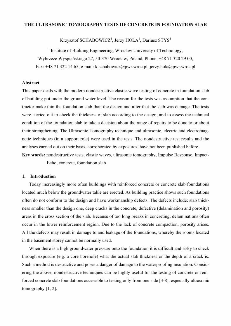
Nondestructive testing of the defective foundation slab began in the large pit where, as pre-
viously mentioned, the leaking of water through the visible crack was most intensive (fig. 1). Line
of bands were marked on the surface of the groundslab. The arrangement of bands and the location
of the crack are shown in fig. 2.
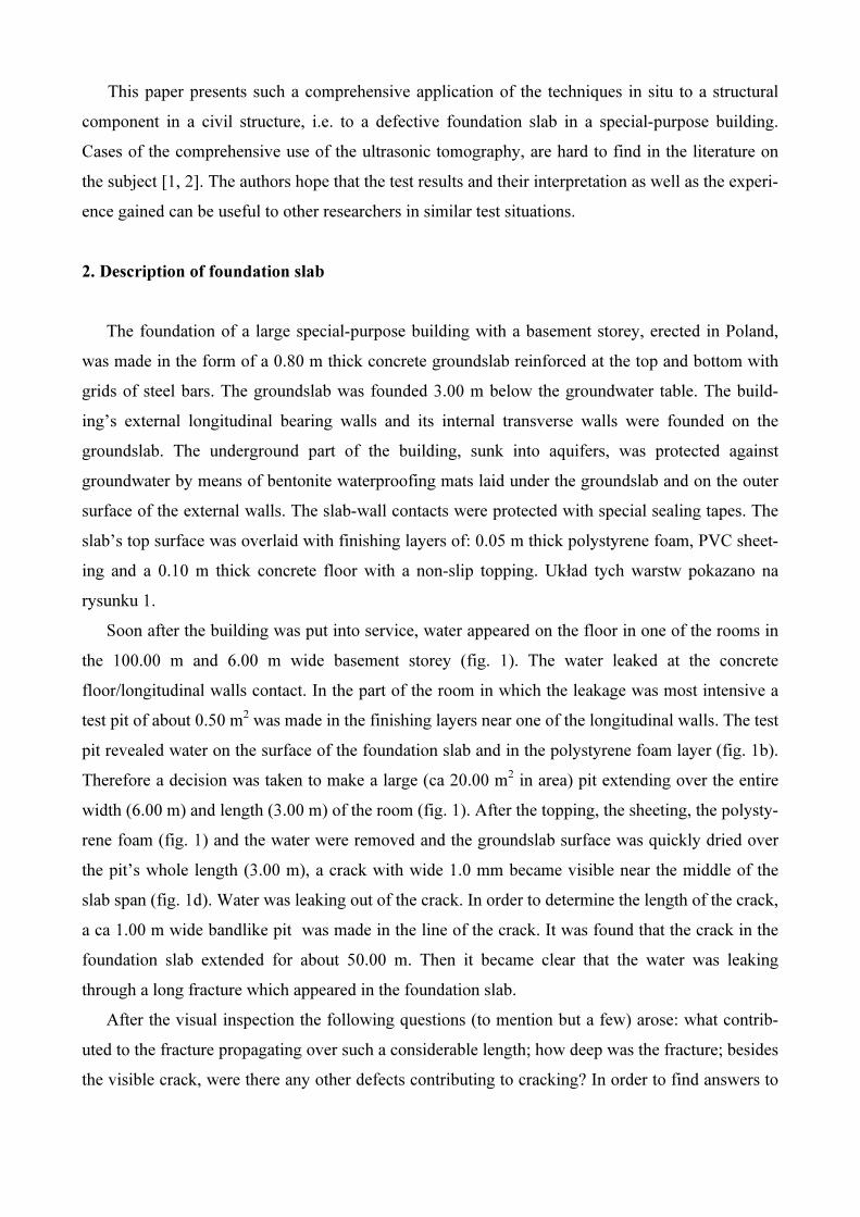
An ultrasonic tomograph (fig. 3) was used for testing. The tomograph is useful for, among
other things, determining the thickness of unilaterally accessible concrete elements and detecting
inhomogeneities such as air voids and highly porous zones. Tests were conducted in four bands
each 0.50 m wide and 6.00 mm length (fig. 2). During testing in a band the tomograph’s antenna
was always shifted in one direction. The total number of measuring points was about 240. The im-
ages of the groundslab cross sections obtained from the particular measuring points were collected
in a three-dimensional matrix column and three mutually intersecting cross sections of the ground-
6 m
a)
concrete
topping
foundation slab
PVC
sheeting
polysty-
rene foam
c) d) e)
b)
longitudinal external
wall
crack in founda-
tion slab
Surface layer
Concrete top ping 100 mm
PVC sheeting
Polistyrene foam 50 mm
Foundation slab 80 mm
slab (scan B, C and D) were produced on the basis of the matrix table. Scan B shows a cross section
of ground slab in the middle of the band. Scan C shows horizontal cross section in the levels of de-
fects. Scan D shows a longitudinal section through ground slab in the band.
Very similar groundslab thickness scans were obtained from the tests performed in the par-
ticular bands. The scans are shown in figures 4-7.
Fig. 2. Grid of line of bands, marked on groundslab within large pit
Fig. 3. Ultrasonic tomograph: a) measuring set, b) testing procedure
a) b)

Fig. 4. Exemplary groundslab thickness scans obtained in band 1 by means of ultrasonic tomo-graph: a) scan C, b) scan D, c) scan B
Fig. 5. Exemplary groundslab thickness scans obtained in band 2 by means of ultrasonic tomo-graph: a) scan C, b) scan D, c) scan B
Fig. 6. Exemplary groundslab thickness scans obtained in band 3 by means of ultrasonic tomo-graph: a) scan C, b) scan D, c) scan B
a)
b) c)
c)
c)
a)
a)
b)
b)
scan C
scan D scan B
scan C
scan C
scan D
scan D
scan B
scan B

Fig. 7. Exemplary groundslab thickness scans obtained in band 4 by means of ultrasonic tomo-graph: a) scan C, b) scan D, c) scan B
An analysis of the obtained scans adopted a very likely that:
- the thickness of the tested foundation slab in the approx. 1.00 m wide zones adjoining the longitu-
dinal external walls was about 0.80 m and conformed to the design,
- the foundation slab thickness in the approx. 4.00 m wide central zone was 0.36-0.40 m and it did
not conform to the design,
- the thinning of the groundslab thickness from 0.80 m to 0.36-0.40 m in the transition zone was
made at an angle of 45o,
- the space under the groundslab in its central zone was probably filled with heterogeneous material,
e.g. construction debris.
Considering the above and the discovery (after the bandlike pit was cut) of the 50 m long
crack in the groundslab, it was decided to remove the finishing layers from the latter. Then addi-
tional nondestructive ultrasonic tomography tests were carried out in randomly selected bands along
the groundslab’s length. Similar results as the ones shown in figs 4-7 were obtained. Therefore it
was concluded that the reduction in the groundslab’s load-bearing capacity could pose a safety risk.
Numerical static-strength analyses were carried out to test this supposition. Their results are sum-
marized in section 4.
c)
a)
b)
scan C
scan D scan B
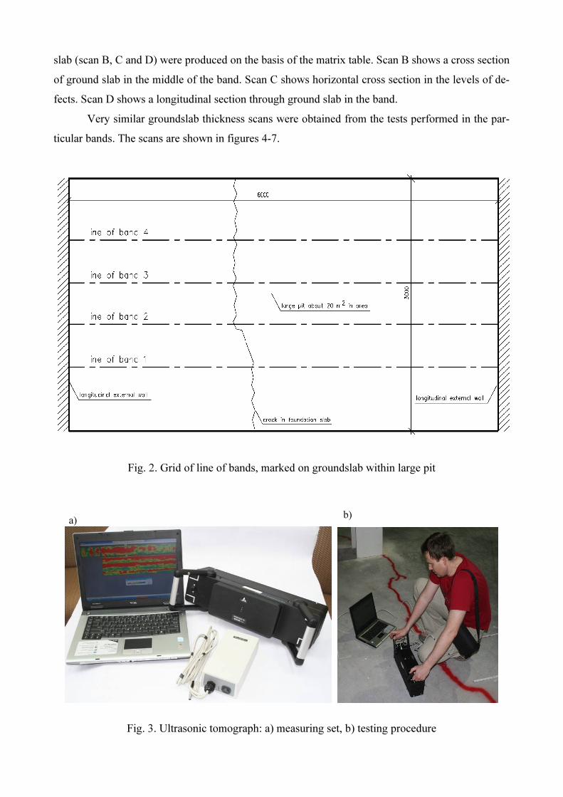
4. Results of numerical analysis
The Autodesk Robot Structural Analysis software was used for the numerical analyses. The
computations were performed for the same loads as those in the building design, taking into account
the reduced groundslab thickness in the central zone. The groundslab’s geometry is shown in fig. 8.
A numerical model of the groundslab with marked supports, and the FE mesh are shown in fig. 9.
The total number of finite elements was 1536. Diagrams of moments in the longitudinal section and
in the cross section are shown in fig. 9.
Fig. 8. Groundslab’s geometry (plan and cross section)
CROSS SECTION A-A
longitudinal
external wall
poles placed
in external walls
foundation slab
ceiling above the room
HORIZONTAL CROSS SECTION
10
00
00

Fig. 9. Groundslab numerical model and calculation results: a) numerical model with marked sup-
ports under columns in external walls, and FE mesh, b) diagram of moment Myy under characteristic
loads in longitudinal section, c) diagram of moment Mxx in cross section between columns in exter-
nal walls, d) diagram of moment Mxx in cross section between columns in external walls
The analyses showed that the groundslab’s load-bearing capacity was exceeded by about
45% relative to the design capacity. Considering this fact, it is not surprising that the 50 m long
crack appeared in the groundslab. As a result of this long crack, the groundslab’s waterproofing
could have been damaged whereby groundwater penetrated onto the basement floor. Having the
safety of the building in mind, a decision was made to repair and reinforce the groundslab.
5. Conclusion
a)
b)
c)
d)
The paper describes how the ultrasonic tomography method was applied to investigate the
groundslab in a special-purpose building. The nondestructive tomographic investigations contrib-
uted to the discovery of a structural defect in this element. It was found that the actual thickness of
the groundslab in the (about 4 m wide) central zone amounted to 0.36-0.40 m, which means that it
did not conform to the design. In the (about 1 m wide) zones adjoining the longitudinal external
walls, groundslab thickness amounted to about 0.80 m, conforming to the design. It was also found
that the reduction in slab thickness in the transition zone from the thickness of 0.80 m to 0.36-0.40
m had been made at an angle of ca 45%. The results of the nondestructive investigations were used
in groundslab load-bearing capacity verification computations. The latter showed that the ground-
slab’s load-bearing capacity was exceeded by about 45% relative to the design capacity. Having the
safety of the building in mind, it was decided to repair and reinforce the groundslab.
Bibliography
[1] Samokrutov A. A., Kozlov V. N., Shevaldykin V. G. Ultrasonic testing of concrete objects using dry
acoustic contact. Methods, instruments and possibilities. The 5th International Conference “Non-
Destructive Testing and Technical Diagnostics in Industry”. Mashinostroenie, p.152. 2006
[2] Bishko A. V., Samokrutov A. A, Shevaldykin V. G Ultrasonic echo-pulse tomography of concrete
using shear waves low-frequency phased antenna arrays. e-Journal of Nondestructive Testing & Ul-
trasonics. e-Journal of Nondestructive Testing & Ultrasonics. vol. 13. 2008
[3] Jerga J., Pokorny M. Damage detection of concrete by nonlinear acoustic testing methods. Civil and
Environmental Engineering. Vol. 3. No. 1. 2007
[4] Rucka M.. Wilde K. Application of continuous wavelet transform in vibration based damage detec-
tion method for beams and plates. Journal of Sound and Vibration 297. 2006
[5] Hoła J., Sadowski Ł., Schabowicz K. Nondestructive evaluation of the concrete floor quality using
impulse response method and impact-echo method. e-Journal of Nondestructive Testing & Ultrason-
ics. Vol. 14 No. 3. 2009
[6] American Concrete Institute Report ACI 228.2R-98. Nondestructive Test Methods for Evaluation of
Concrete in Structures. ACI. Farmington Hills, Michigan. 1998.
[7] Bungey J., Millard S., Gratham M. Testing of concrete in structures. Taylor&Francis. London and
New York. 2006
[8] Garbacz A. Nondestructive investigations of polymer-concrete composites using stress waves – re-
pair efficiency evaluation (in polish). Prace naukowe. Budownictwo z. 147, Oficyna Wydawnicza
Politechniki Warszawskiej. 2007