the udact-f - alarmhow.net
TRANSCRIPT

© 1997 Fire•Lite Alarms, Inc.
Document # 50049Document # 50049Document # 50049Document # 50049Document # 500495/2/97 Rev:5/2/97 Rev:5/2/97 Rev:5/2/97 Rev:5/2/97 Rev: D
P/N 50049:D ECN 97-17312 Clintonville Road, Northford, CT 06472
The UDACT-FUniversal Digital Alarm Communicator/Transmitter
Product Information, Installation,Programming and Operation Manual

WARNING: This equipment generates, uses, and can radiate radio frequencyenergy and if not installed and used in accordance with the instruction manual, maycause interference to radio communications. It has been tested and found to complywith the limits for class A computing device pursuant to Subpart B of Part 15 of FCCRules, which is designed to provide reasonable protection against such interferencewhen operated in a commercial environment. Operation of this equipment in aresidential area is likely to cause interference, in which case the user will be requiredto correct the interference at his own expense.
Installation Precautions - Adherence to the following will aid in problem-free installation with long-term reliability:
WARNING - Several different sources of power can be connected to the fire alarmcontrol panel. Disconnect all sources of power before servicing. Control unit andassociated equipment may be damaged by removing and/or inserting cards,modules, or interconnecting cables while the unit is energized. Do not attempt toinstall, service, or operate this unit until this manual is read and understood.
CAUTION - System Reacceptance Test after Software Changes: To ensureproper system operation, this product must be tested in accordance with NFPA 72-1993 Chapter 7 after any programming operation or change in site-specific software.Reacceptance testing is required after any change, addition or deletion of systemcomponents, or after any modification, repair or adjustment to system hardware orwiring.
All components, circuits, system operations, or software functions known to beaffected by a change must be 100% tested. In addition, to ensure that otheroperations are not inadvertently affected, at least 10% of initiating devices that arenot directly affected by the change, up to a maximum of 50 devices, must also betested and proper system operation verified.
This system meets NFPA requirements for operation at 0-49O C/32-120O Fand at a relative humidity of 85% RH (non-condensing) at 30O C/86O F.However, the useful life of the system's standby batteries and the electroniccomponents may be adversely affected by extreme temperature ranges andhumidity. Therefore, it is recommended that this system and its peripherals beinstalled in an environment with a nominal room temperature of 15-27O C/60-80O
F.
Verify that wire sizes are adequate for all initiating and indicating device loops.Most devices cannot tolerate more than a 10% I.R. drop from the specified devicevoltage.
Like all solid state electronic devices, this system may operate erratically or canbe damaged when subjected to lightning induced transients. Although no system iscompletely immune from lightning transients and interferences, proper grounding willreduce susceptibility. Overhead or outside aerial wiring is not recommended, due toan increased susceptibility to nearby lightning strikes. Consult with the TechnicalServices Department if any problems are anticipated or encountered.
Disconnect AC power and batteries prior to removing or inserting circuit boards.Failure to do so can damage circuits.
Remove all electronic assemblies prior to any drilling, filing, reaming, or punchingof the enclosure. When possible, make all cable entries from the sides or rear.Before making modifications, verify that they will not interfere with battery,transformer, and printed circuit board location.
Do not tighten screw terminals more than 9 in-lbs. Over tightening may damagethreads, resulting in reduced terminal contact pressure and difficulty with screwterminal removal.
This system contains static-sensitive components. Always ground yourself with aproper wrist strap before handling any circuits so that static charges are removedfrom the body. Use static suppressive packaging to protect electronic assembliesremoved from the unit.
Follow the instructions in the installation, operating, and programming manuals.These instructions must be followed to avoid damage to the control panel andassociated equipment. FACP operation and reliability depend upon properinstallation.
Fire Alarm System Limitations While installing a fire alarm system may make lower insurancerates possible, it is not a substitute for fire insurance!
An automatic fire alarm system - typically made up of smoke detectors, heatdetectors, manual pull stations, audible warning devices, and a fire alarm controlwith remote notification capability can provide early warning of a developing fire.Such a system, however, does not assure protection against property damage orloss of life resulting from a fire.
Any fire alarm system may fail for a variety of reasons:
Smoke detectors may not sense fire where smoke cannot reach the detectors suchas in chimneys, in walls, or roofs, or on the other side of closed doors. Smokedetectors also may not sense a fire on another level or floor of a building. A secondfloor detector, for example, may not sense a first floor or basement fire. Further-more, all types of smoke detectors - both ionization and photoelectric types, havesensing limitations. No type of smoke detector can sense every kind of fire causedby carelessness and safety hazards like smoking in bed, violent explosions,escaping gas, improper storage of flammable materials, overloaded electricalcircuits, children playing with matches, or arson.
IMPORTANT! Smoke detectors must be installed in the same room as thecontrol panel and in rooms used by the system for the connection of alarmtransmission wiring, communications, signaling, and/or power. If detectors arenot so located, a developing fire may damage the alarm system, crippling itsability to report a fire.
Audible warning devices such as bells may not alert people if these devices arelocated on the other side of closed or partly open doors or are located on anotherfloor of a building.
A fire alarm system will not operate without any electrical power. If AC power fails,the system will operate from standby batteries only for a specified time.
Rate-of-Rise heat detectors may be subject to reduced sensitivity over time. Forthis reason, the rate-of-rise feature of each detector should be tested at least onceper year by a qualified fire protection specialist.
Equipment used in the system may not be technically compatible with the control.It is essential to use only equipment listed for service with your control panel.
Telephone lines needed to transmit alarm signals from a premise to a centralmonitoring station may be out of service or temporarily disabled.
The most common cause of fire alarm malfunctions, however, is inadequatemaintenance. All devices and system wiring should be tested and maintained byprofessional fire alarm installers following written procedures supplied with eachdevice. System inspection and testing should be scheduled monthly or as requiredby National and/or local fire codes. Adequate written records of all inspections shouldbe kept.
FCC WarningCanadian RequirementsThis digital apparatus does not exceed the Class A limits for radiation noiseemissions from digital apparatus set out in the Radio Interference Regulations of theCanadian Department of Communications.
Le present appareil numerique n'emet pas de bruits radioelectriques depassant leslimites applicables aux appareils numeriques de la classe A prescrites dans leReglement sur le brouillage radioelectrique edicte par le ministere des Communica-tions du Canada.
Technical Publishing Document PRECAULG.P65 12/31/96

3Document # 50049 Rev D 5/2/97 P/N 50049:D
Tabl
e of
Con
tent
sNFPA Standards, UL Documents 5
1.0 Product Description 61.1 Product Features 6
Figure 1-1: UDACT-F Assembly 71.2 Controls and Indicators 8
Figure 1-2: Controls and Indicators 81.3 Compatible Panels 81.4 Digital Communicator 81.5 Circuits 9
1.5.1 Power Requirements 91.5.2 Communications 91.5.3 Primary and Secondary Phone Lines 91.5.4 Communicator Fail Relay Driver 91.5.5 Earth Ground 9
1.6 Specifications 101.7 Telephone Requirements and Warnings 10
1.7.1 Telephone Circuitry 101.7.2 Digital Communicator 101.7.3 Telephone Company Rights and Warnings 101.7.4 For Canadian Applications 11
1.8 Modes and Special Functions 121.8.1 Normal Mode 121.8.2 Program Mode 121.8.3 Lamp Test Mode 121.8.4 Troubleshoot Mode 121.8.5 Type Mode 121.8.6 Clear Function 121.8.7 Manual Test Function 12
2.0 Installation 132.1 General 13
Figure 2-1: ABS-8RF 132.2 Panel Mounting 13
2.2.1 MS-9200 13Figure 2-2: UDACT-F Mounting to MS-9200 13Figure 2-3: External UDACT-F Mounting in ABS-8RF 14Table 2-1: Annunciator LED Assignments - MS-9200 152.2.2 Sensiscan 2000 16Figure 2-4: UDACT-F Mounting in CHS-4 16Figure 2-5: EIA-485 Connection Sensiscan 2000 17Figure 2-6: 24VDC Power Connection to UDACT-F 18Table 2-2: Annunciator LED Assignments - S-2000 19
2.3 UL Power-limited Wiring Requirements 20Figure 2.7: Typical Wiring Diagram UL Power-limited 20
2.3 Output Circuits 21Figure 2-8: Wiring Phone Jacks 21Figure 2-9: Relay Driver Connections 22Figure 2-10: Monitoring for UDACT Trouble 23
3.0 Programming Instructions 243.1 Entering Program Mode 243.2 Switch Functions 25
Figure 3-1: UDACT-F Keypad 25

4 Document # 50049 Rev D 5/2/97 P/N 50049:D
Tabl
e of
Con
tent
s3.3 Programming Options 25
Table 3-1: Start and End Monitoring Address 28Table 3-2: Event Codes, Primary Number 30Table 3-3: Event Codes, Primary Number 31Table 3-4: Ademco Contact ID, Primary Number 32Table 3-5: Event Codes, Secondary Number 33Table 3-6: Event Codes, Secondary Number 34Table 3-7: Ademco Contact ID, Secondary Number 35
4.0 Operating Instructions 364.1 Normal Mode 36
4.1.1 Keys 364.1.2 Displays 37Figure 4-1: UDACT-F Phone Connectors & LEDs 384.1.3 Normal Mode Operation 384.1.4 Key Report Descriptions 40
4.2 Type Mode 404.2.1 Disabling of Zones or Points 414.2.2 Zone or Point Supervisory 41
4.3 Troubleshoot Mode 424.4 Lamp Test Mode 42
Figure 4-2: Handset/Speaker Connection 42
Appendix A: Reporting Formats 43
Appendix B: Compatible Receivers 47
Appendix C: Programming Reference Sheets 48
Appendix D: Point Assignments (Addr. 56 = 3 or 4) 52
Appendix E: Point Assignments (Addr. 56 = 5 or 6) 53
Appendix F: Zone Assignments 54

5Document # 50049 Rev D 5/2/97 P/N 50049:D
This control panel has been designed to comply with standards set forth by the followingregulatory agencies: • Underwriters Laboratories Standard UL 864 • NFPA Standards 72-1993 Local, Remote Station and Central Station Fire Alarm Systems • CAN/ULC - S527-M87 Standard for Control Units for Fire Alarm Systems
Before proceeding, the installer should be familiar with the following documents.
NFPA Standards, NFPA 72-1993 National Fire Alarm Code:• Central Station Fire Alarm Systems (Automatic, Manual and Waterflow) Protected Premises Unit.• Local (Automatic, Manual, Waterflow and Sprinkler Supervisory) Fire Alarm Systems.• Proprietary Fire Alarm Systems (Protected Premises Unit).• Automatic Fire Detectors• Installation, Maintenance, and Use of Notification Appliances for Fire Alarm Systems• Inspection, Testing and Maintenance for Fire Alarm Systems
FM Approved (with Ademco 685 Receiver)
Underwriters Laboratories Documents:UL 38 Manually Actuated Signaling BoxesUL 217 Smoke Detectors, Single and Multiple StationUL 228 Door Closers—Holders for Fire Protective Signaling SystemsUL 268 Smoke Detectors for Fire Protective Signaling SystemsUL 268A Smoke Detectors for Duct ApplicationsUL 346 Waterflow Indicators for Fire Protective Signaling SystemsUL 464 Audible Signaling AppliancesUL 521 Heat Detectors for Fire Protective Signaling SystemsUL 864 Standard for Control Units for Fire Protective Signaling SystemsUL 1481 Power Supplies for Fire Protective Signaling SystemsUL 1638 Visual Signaling AppliancesCAN/ULC - S524-M91 Standard for Installation of Fire Alarm Systems
Other:NEC Article 300 Wiring MethodsNEC Article 760 Fire Protective Signaling SystemsApplicable Local and State Building CodesRequirements of the Local Authority Having Jurisdiction
6 Document # 50049 Rev D 5/2/97 P/N 50049:D
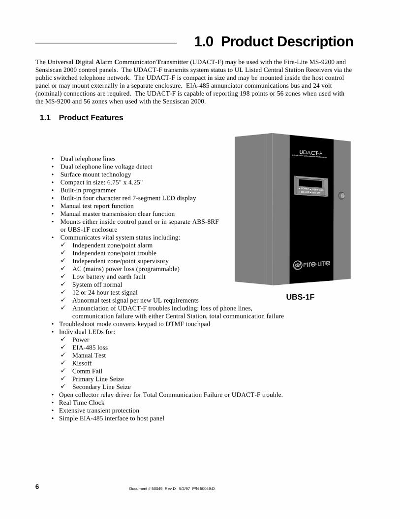
1.0 Product DescriptionThe Universal Digital Alarm Communicator/Transmitter (UDACT-F) may be used with the Fire-Lite MS-9200 andSensiscan 2000 control panels. The UDACT-F transmits system status to UL Listed Central Station Receivers via thepublic switched telephone network. The UDACT-F is compact in size and may be mounted inside the host controlpanel or may mount externally in a separate enclosure. EIA-485 annunciator communications bus and 24 volt(nominal) connections are required. The UDACT-F is capable of reporting 198 points or 56 zones when used withthe MS-9200 and 56 zones when used with the Sensiscan 2000.
1.1 Product Features
• Dual telephone lines• Dual telephone line voltage detect• Surface mount technology• Compact in size: 6.75" x 4.25"• Built-in programmer• Built-in four character red 7-segment LED display• Manual test report function• Manual master transmission clear function• Mounts either inside control panel or in separate ABS-8RF
or UBS-1F enclosure• Communicates vital system status including:ü Independent zone/point alarmü Independent zone/point troubleü Independent zone/point supervisoryü AC (mains) power loss (programmable)ü Low battery and earth faultü System off normalü 12 or 24 hour test signalü Abnormal test signal per new UL requirementsü Annunciation of UDACT-F troubles including: loss of phone lines, communication failure with either Central Station, total communication failure
• Troubleshoot mode converts keypad to DTMF touchpad• Individual LEDs for:ü Powerü EIA-485 lossü Manual Testü Kissoffü Comm Failü Primary Line Seizeü Secondary Line Seize
• Open collector relay driver for Total Communication Failure or UDACT-F trouble.• Real Time Clock• Extensive transient protection• Simple EIA-485 interface to host panel
UBS-1F

7Document # 50049 Rev D 5/2/97 P/N 50049:D
Figure 1-1: UDACT-F Assembly
Connector onback of board
PrimaryPhone Line Secondary
Phone Line
Modular CablesP/N MCBL-7(Order Separately)
(Connect to J16on MS-9200 only)
24VDC Power in(use power-limitedsource)
EIA-485 Connector(use power-limitedsource)
Comm Fail Output(power-limited)
24 VDC(power-limited)

8 Document # 50049 Rev D 5/2/97 P/N 50049:D
1.2 Controls andIndicators
Front Panel SwitchesCLEAR Digits 0-9TEST AMODE BUp Arrow CDown Arrow D1st EVENT EENTER/STORE F
Displays• EIA-485 - yellow LED• COMM. FAIL - yellow LED• KISS OFF - green LED• POWER - green LED• Four, Seven Segment Displays - red• Primary Phone Line Active - red LED• Secondary Phone Line Active - red LED• TEST - green LED
The UDACT-F has been designed to be compatible with the following Fire-Litecontrol panels:
• Sensiscan 2000• MS-9200.
Two modular phone jacks allow easy connection to telephone lines. Modular jacksare labeled PH1 and PH2 for the Primary and Secondary phone lines. Telephone line'Primary and Secondary Active' red LEDs are provided as well as a green 'Kissoff'LED. The integral digital communicator provides the following functions:
• Line Seizure - takes control of the phone lines disconnecting any premisesphones.
• Off/On Hook - perform on and off-hook status to the phone lines.
• Listen for dial tone - 440 hertz tone typical in most networks.
• Dialing the Central Station(s) number - default is Touch-Tone®,programmable to rotary.
• For tone burst or touchtone type formats: Discern proper 'Ack' and 'Kissoff'tone(s) - The frequency and time duration of the tone(s) varies with thetransmission format. The UDACT-F will adjust accordingly.
• Communicate in the following formats (refer to Appendix for compatiblereceivers:✓6 Tone Burst Types: 20 pps (3+1, 4+1, 4+2)✓ 3 Touchtone Types: 4 + 1 Ademco Express 4 + 2 Ademco Express Ademco Contact ID
Figure 1-2: Controls and Indicators
1.3 Compatible Panels
1.4 Digital Communicator

9Document # 50049 Rev D 5/2/97 P/N 50049:D
The UDACT-F circuit board contains a CPU, other primary components and wiringinterface connectors.
1.5.1 Power RequirementsOperating voltage for the UDACT-F must be power-limited, filtered, nonresettable21.2 to 28.2 volts. The 24 VDC nominal operating power must be supplied by theControl Panel and is connected to TB1 of the UDACT-F.Note: If the UDACT-F is installed in an MS-9200 Control Panel, power is provideddirectly through UDACT-F connector J10 which plugs into the MS-9200 main circuitboard.
1.5.2 CommunicationsCommunications between the UDACT-F and the host control panel is accomplishedover a two wire EIA-485 serial interface which is power-limited and supervised bythe control panel and the UDACT-F. The wiring connections are made to the RS+,RS- and Shield terminals of TB1 on the UDACT-F.
The EIA-485 circuit cannot be T-Tapped and must be wired in a continuous fashionfrom the control panel to the UDACT-F and, if installed, an annunciator. The wiremust be 12AWG to 18AWG twisted shielded pair cable with a CharacteristicImpedance of 120 Ohms, +/-20%. Limit the total wire resistance to 100 Ohms on theEIA-485 circuit. Do not run cable adjacent to, or in the same conduit as 120 voltsAC service, noisy electrical circuits that are powering mechanical bells or horns,audio circuits above 25 volts
RMS, motor control circuits, or SCR power circuits.
Note: If the UDACT-F is installed in an MS-9200 Control Panel, the EIA-485 dataline is connected directly through UDACT-F connector J10 which plugs into the MS-9200 main circuit board.
1.5.3 Primary and Secondary Phone Lines - Modular jacks are used to interfacethe primary and secondary phone lines to the public telephone network.
1.5.4 Communicator Fail Relay Driver - Relay driver output for Central Stationcommunication failure is available.
1.5.5 Earth Ground - Connect a separate earth ground wire to TB3 terminal 1 fortransient protection. When mounted in the MS-9200, the UDACT-F receives anearth ground connection via a metal standoff located on the upper right cornermounting position.
DC Power - TB1, Terminals 1 & 224VDC (nominal) filtered, nonresettable and power-limited. Voltage range is 21.2 to28.2 volts. DC Power TB1 Terminals 1 (+), 2 (-) 40 mA in standby, 75 mA max.while communicating (for MS-9200 installation use connector J10) and 100 mA withthe open collector output engaged and communicating.
Data Communications - TB1, Terminals 3 - 7EIA-485 serial interface, TB1 Terminal 3 = RS+, 4 = RS-, 5= Shield, 6 = Future use,7 = Future use. Power-limited source must be used. (For MS-9200 installation useconnector J10).
Auxiliary Output - TB3, Terminals 2 & 3TB3-2 = Communicator Failure. Power-limited circuit. An Open Collector typeoutput, normally high, active low which sinks up to 40 mA. TB3-3 = 21.2 to 28.2volts, power-limited. Use UL listed relay P/N: MR-101/C or MR-201/C with thisoutput.
1.5 Circuits
1.6 Specifications

10 Document # 50049 Rev D 5/2/97 P/N 50049:D
Earth Ground - TB3, Terminal 1TB3-1 = Earth Ground connection. Connect this terminal to building earth groundusing solid 12 AWG wire to provide lightning protection. This connection is notrequired when the UDACT-F is mounted in an MS-9200 since the metal standoffused in mounting provides an earth ground connection.
1.7.1 Telephone Circuitry - PH1 & PH2Ringer Equivalence Number (REN) = 0.6BAC Impedance 10.0 Mega OhmComplies with FCC Part 68Mates with RJ31X Male ConnectorSupervision Threshold: less than 4.0 volts for 2 minutes
The REN is used to determine the quantity of devices which may be connected to thetelephone line. Excessive REN's on the telephone line may result in the devices notringing in response to an incoming call. In most, but not all areas, the sum of theREN's should not exceed five (5.0). To be certain of the number of devices that maybe connected to the line, as determined by the total REN's, contact the telephonecompany to determine the maximum REN for the calling area.
1.7.2 Digital Communicator:Before connecting the UDACT-F to the public switched telephone network, theinstallation of two RJ31X jacks is necessary. The following information is providedif required by the local telephone company :
Manufacturer : Fire·Lite Alarms Inc.12 Clintonville Rd.Northford, CT 06472
Product Model Number: UDACT-FFCC Registration Number: 1W6USA-20723-AL-ERinger Equivalence 0.6B
1.7.3 Telephone Company Rights and Warnings:The telephone company under certain circumstances may temporarily discontinueservices and/or make changes in its facilities, services, equipment or procedureswhich may affect the operation of this control panel. However, the telephonecompany is required to give advance notice of such changes or interruptions.
If the control panel causes harm to the telephone network, the telephone companyreserves the right to temporarily discontinue service. Advance notification will beprovided except in cases when advance notice is not practical. In such cases,notification will be provided as soon as possible. The opportunity will be given tocorrect any problems and to file a complaint.
DO NOT CONNECT THIS PRODUCT TO COIN TELEPHONE, GROUND START,OR PARTY LINE SERVICES.
When the control panel activates, premise phones will be disconnected.
Two separate phone lines are required. Do not connect both telephone interfaces tothe same telephone line.
The control panel must be connected to the public switched telephone networkupstream of any private telephone system at the protected premises.
1.7 TelephoneRequirementsand Warnings

11Document # 50049 Rev D 5/2/97 P/N 50049:D
An FCC compliant telephone cord must be used with this equipment. This equipmentis designed to be connected to the telephone network or premises wiring using acompatible RJ31X male modular plug which is Part 68 compliant.
1.7.4 For Canadian ApplicationsThe following is excerpted from CP-01 Issue 5:"NOTICE: The Canadian Department of Communications label identifies certifiedequipment. This certification means that the equipment meets certaintelecommunications network protective, operational and safety requirements. TheDepartment does not guarantee the equipment will operate to the user's satisfaction.
Before installing this equipment, users should ensure that it is permissible to beconnected to the facilities of the local telecommunications company. Theequipment must also be installed using an acceptable method of connection. Insome cases, the company's inside wiring associated with a single line individualservice may be extended by means of a certified connector assembly (telephoneextension cord). The customer should be aware that compliance with the aboveconditions may not prevent degradation of service in some situations.
Repairs to certified equipment should be made by an authorized Canadianmaintenance facility designated by the supplier. Any repairs or alterations made bythe user to this equipment, or equipment malfunctions, may give thetelecommunications company cause to request the user to disconnect the equipment.
Users should ensure for their own protection that the electrical ground connectionsof the power utility, telephone lines and internal metallic water pipe system, ifpresent, are connected together. This precaution may be particularly important inrural areas.
Caution: Users should not attempt to make such connections themselves, but shouldcontact the appropriate electric inspection authority, or electrician, as appropriate."
"The Load Number (LN) assigned to each terminal device denotes the percentage ofthe total load to be connected to a telephone loop which is used by the device, toprevent overloading. The termination on a loop may consist of any combination ofdevices subject only to the requirement that the total of the Load Numbers of all thedevices does not exceed 100."
DOC Compliance - "This digital apparatus does not exceed the Class A limits forradio noise emissions from digital apparatus set out in the Radio InterferenceRegulations of the Canadian Department of Communications."
DOC Registration Number: 2132 6030 ALoad Number: 3

12 Document # 50049 Rev D 5/2/97 P/N 50049:D
1.8.1 Normal Mode:Normal mode is the standard mode of operation. In this mode, the UDACT-Fmonitors host FACP status as well as monitoring telephone line voltage. TheUDACT-F reports system status information to UL listed Central Stations.Information transmitted includes general alarm, trouble and supervisory. It alsotransmits either the number of zones or points activated or the specific point(s)activated. Specific system trouble conditions and specific UDACT-F troubles arealso transmitted.
1.8.2 Program Mode:Program mode is used to program the UDACT-F. While the UDACT-F is in theprogram mode, it cannot receive host FACP status information. See Section 3.0 forcomplete programming instructions.
1.8.3 Lamp Test Mode:This mode turns on all segments of the 4 character display plus all LEDs on theUDACT-F.
1.8.4 Troubleshoot Mode:Troubleshoot mode may be used for testing the telephone line wiring. Connectionfrom the UDACT's modular jacks, through RJ31X jacks and into the telephonenetwork may be easily checked. In this mode, the keypad acts similar to a telephonetouchpad.
1.8.5 Type ModeType mode is used to define the specific type of device (point) used or function of azone. This mode is also used to disable the alarm report for any zone/point in thesystem. The feature which disables the zone/point alarm report must be used forzones/points programmed into the host FACP as remote silence, reset, drill oracknowledge switches.
1.8.6 Clear Function:When the clear function is activated, it causes the UDACT-F to immediately stoptransmissions, hang-up from the telephone network, clear out any messages thatwere waiting for transmission and reset.
1.8.7 Manual Test Function:The manual test function allows for a test report message to be sent to both CentralStations upon activation.
1.8 Modes and Special Functions

13Document # 50049 Rev D 5/2/97 P/N 50049:D
Mounting OptionsThe UDACT-F may be mounted in the control panel or mountedremotely in an ABS-8RF or UBS-1F enclosure up to 6000 feet awayfrom the control panel. All power must be removed from the ControlPanel before making any connections to prevent circuit damage. TheEIA-485 serial interface is connected between the Control Panel andUDACT-F using twisted, shielded pair wire. Power should be wiredfrom the Control Panel's 24VDC (nominal) filtered, nonresettableoutput to TB1 on the UDACT-F (except when mounted in the MS-9200).
2.2.1 MS-9200The MS-9200 must have firmware with a Part Number of 73580 or higher installed toallow use of the UDACT-F. Remove all power from the MS-9200 by disconnectingAC and batteries. Install the supplied standoffs (three nylon and one aluminum standoff)in the appropriate holes located on the right side of the MS-9200 main circuit board asillustrated in Figure 2-2. Position J10 located on the back of the UDACT-F over connectorJ16 which is located center right on the main MS-9200 circuit board, and carefullyconnect. Secure the UDACT-F to the aluminum standoff with the screw provided.
The EIA-485 circuit and 24VDC power are provided directly from connector J16 ofthe MS-9200. Note: A 120 ohm EOL resistor is not required on the UDACT-F EIA-485 terminals when it is installed inside the MS-9200 cabinet. The EOL resistor is requiredat the last device on the EIA-485 line external to the MS-9200 panel.
2.1 General
2.0 Installation
Figure 2-2: UDACT-F Mounting to MS-9200
Figure 2-1: ABS-8RF
2.2 Panel Mounting
MS-9200 3/4" aluminum standoffwith nut required fortransient protection
UDACT-F
3/4" NylonStandoffs

14 Document # 50049 Rev D 5/2/97 P/N 50049:D
Notes:1) This arrangement allows use of the UDACT-F simultaneously with the RTM-8F module.2) Ferrite cores are recommended for all applications.3) Recommended wire is 12 AWG to 18 AWG twisted pair.4) Shielded wire is not required (unless mandated by local AHJ). If shielded wire is used, connect only one end of shield:
a) shield may be connected to cabinet (earth ground) at fire alarm panel, orb) shield may be connected to TB1 Terminal 5 (Shield) at UDACT-F as shown in Figure 2-3. NOTE: The shield end that is not connected should be insulated to prevent accidental grounding. Do not connect both ends of shield under any circumstance since a ground fault may result.
5) Conduit is recommended for external wire runs. Consult local building codes.6) Connect Ground Strap (supplied with ABS-8RF enclosure) from Earth Ground terminal on UDACT-F to a solid building earth ground. Conduit alone will not provide a reliable earth ground.7) UDACT-F may be located up to 6000 feet away from the host control panel.8) Refer to Specifications for power requirements.
MS-9200
UDACT-F in ABS-8RF(shown with cover removed)
Install 120 ohm EOLresistor (P/N: 71244)on TB1 terminals 3& 4 if last or onlydevice on EIA-485line.
MS-9200Cabinet
FerriteCoresP/N 29090
Figure 2-3: External UDACT-F Mounting in ABS-8RF
Supervised and Power-limited EIA-485 and power connections
ToPhoneLines(Supervised)
SolidEarthGroundConnection
+24 VDCNonresettablePower
Do Not Usethese terminals

15Document # 50049 Rev D 5/2/97 P/N 50049:D
Caution: Connecting a UDACT-F to an MS-9200 which also has an AFM or LDM seriesannunciator connected will alter the assignments of the first eight yellow LEDs on theannunciator as follows:
Table 2-1: Annunciator LED Assignments - MS-9200
MS-9200
Yellow Annunciator LED AssignmentWithout UDACT-F
AssignmentWith UDACT-F
1 System Trouble(less AC loss)
System Trouble(less AC loss)
2 Signals Silenced Signals Silenced
3 Not Used Program Mode(Panel Off Normal)
4 Not Used Supervisory
5 Supervisory Bell Trouble
6 Prealarm Prealarm/Maint. Alert
7 AC Fail Low Battery
8 Panel Trouble AC Fail
16 Document # 50049 Rev D 5/2/97 P/N 50049:D
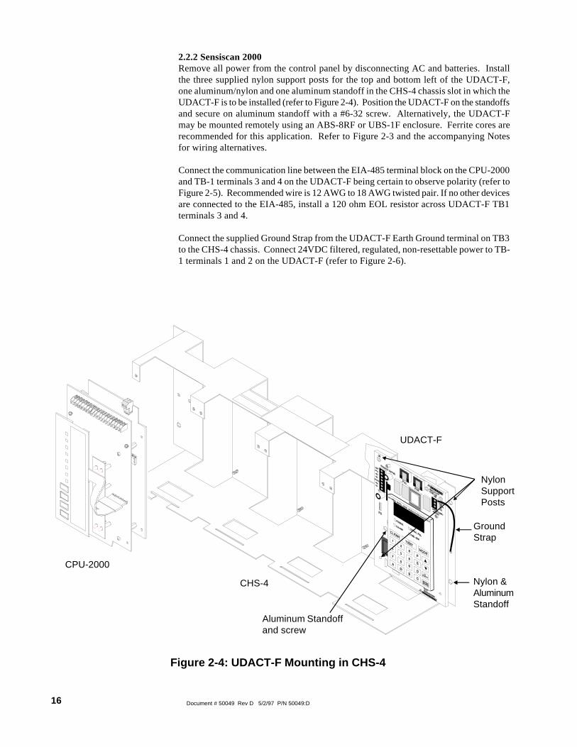
2.2.2 Sensiscan 2000Remove all power from the control panel by disconnecting AC and batteries. Installthe three supplied nylon support posts for the top and bottom left of the UDACT-F,one aluminum/nylon and one aluminum standoff in the CHS-4 chassis slot in which theUDACT-F is to be installed (refer to Figure 2-4). Position the UDACT-F on the standoffsand secure on aluminum standoff with a #6-32 screw. Alternatively, the UDACT-Fmay be mounted remotely using an ABS-8RF or UBS-1F enclosure. Ferrite cores arerecommended for this application. Refer to Figure 2-3 and the accompanying Notesfor wiring alternatives.
Connect the communication line between the EIA-485 terminal block on the CPU-2000and TB-1 terminals 3 and 4 on the UDACT-F being certain to observe polarity (refer toFigure 2-5). Recommended wire is 12 AWG to 18 AWG twisted pair. If no other devicesare connected to the EIA-485, install a 120 ohm EOL resistor across UDACT-F TB1terminals 3 and 4.
Connect the supplied Ground Strap from the UDACT-F Earth Ground terminal on TB3to the CHS-4 chassis. Connect 24VDC filtered, regulated, non-resettable power to TB-1 terminals 1 and 2 on the UDACT-F (refer to Figure 2-6).
Figure 2-4: UDACT-F Mounting in CHS-4
CPU-2000
UDACT-F
CHS-4
NylonSupportPosts
Aluminum Standoffand screw
Nylon &AluminumStandoff
GroundStrap

17Document # 50049 Rev D 5/2/97 P/N 50049:D
Figure 2-5: EIA-485 Connection Sensiscan 2000
CPU-2000
UDACT-F
-
-
+
+
Install 120 ohmEOL resistor (P/N: 71244) acrossterminals 3(RS+) & 4 (RS-)if last or onlydevice on EIA-485 line. Notethat Terminals 6(RS+) & 7 (RS-)are not used atthis time.
TB-1Terminal 3 RS+Terminal 4 RS-
EIA-485 (Supervised andPower-limited)

18 Document # 50049 Rev D 5/2/97 P/N 50049:D
Figure 2-6: 24VDC Power Connection to UDACT-F
+ -
- TB2-2
TB1-1 +
-TB1-2
Power (Supervised andPower-limited)
+TB2-1
UDACT-F
MPS-24BF
Note: Power for the UDACT-F must be 24VDC filtered, regulated non-resettable.
Cut jumper JP1 to makeoutput nonresettable foruse with UDACT
MPS-24AF
Power (Supervised andPower-limited)
TB3-3 TB3-4
+TB1-1
-TB1-2
UDACT-F

19Document # 50049 Rev D 5/2/97 P/N 50049:D
Caution: Connecting a UDACT-F to a Sensiscan 2000 which also has an AFM or LDMseries annunciator connected will alter the assignments of the first eight yellow LEDson the annunciator as follows:
Sensiscan 2000
Yellow Annunciator LED AssignmentWithout UDACT-F
AssignmentWith UDACT-F
1 System Trouble(less AC loss)
System Trouble(less AC loss)
2 Signals Silenced Signals Silenced
3 Not Used Not Used
4 Supervisory Supervisory
5 Indicating Ckt 1 Trouble Indicating Ckt 1 Trouble
6 Indicating Ckt 2 Trouble Indicating Ckt 2 Trouble
7 Municipal Tie Trouble Low Battery/Ground Fault
8 AC Fail AC Fail
Table 2-2: Annunciator LED Assignments - S-2000
20 Document # 50049 Rev D 5/2/97 P/N 50049:D
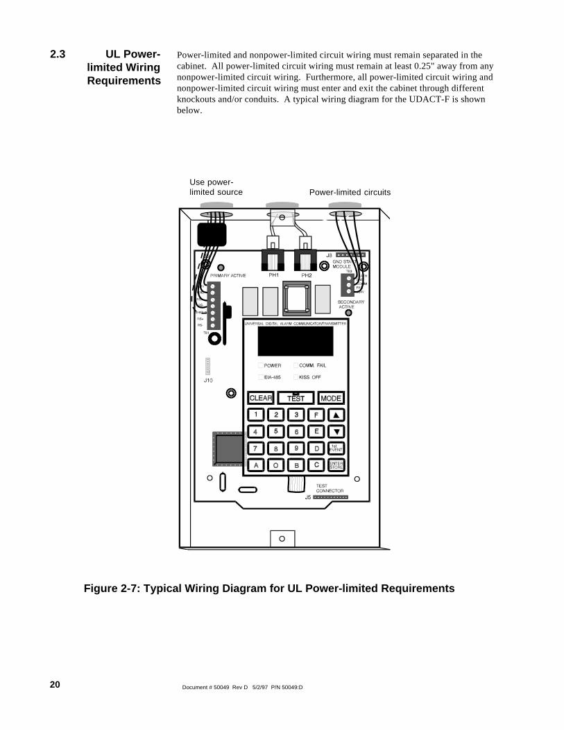
Power-limited and nonpower-limited circuit wiring must remain separated in thecabinet. All power-limited circuit wiring must remain at least 0.25" away from anynonpower-limited circuit wiring. Furthermore, all power-limited circuit wiring andnonpower-limited circuit wiring must enter and exit the cabinet through differentknockouts and/or conduits. A typical wiring diagram for the UDACT-F is shownbelow.
2.3 UL Power- limited Wiring Requirements
Figure 2-7: Typical Wiring Diagram for UL Power-limited Requirements
Use power-limited source Power-limited circuits

21Document # 50049 Rev D 5/2/97 P/N 50049:D
Telephone CircuitsProvision to connect to two independent telephone lines is available via twotelephone jacks labeled PH1 (Primary) and PH2 (Secondary). Telephone line control/command is possible via double line seizure as well as usage of an RJ31X styleinterconnection. (RJ31X jacks must be ordered separately).Note: It is critical that the UDACT-F be located as the first device on the incomingtelephone circuit to properly function.
Note: Shorting barsinside RJ31X Jackremoved during maleplug insertion
SecondaryPhone LinePH-2
PrimaryPhone LinePH-1
7 footCable(MCBL-7)
Order Separately
Male PlugConnectors
Modular FemaleConnectors
(Primary Lines)Incoming TelcoPhone Lines
Ring
Tip
Tip
RingGreen Wire
Green Wire
(Secondary Lines)Incoming TelcoPhone Lines
Red Wire
Red Wire
To premise phonesTo premise phones
Tip
RingRing
Tip
Figure 2-8: Wiring Phone Jacks
2.4 Output Circuits

22 Document # 50049 Rev D 5/2/97 P/N 50049:D
Relay DriverThe UDACTF's open collector output on TB3, terminal 2 is provided for Communi-cator Failure and UDACT-F trouble. It can be used to drive UL listed relay MR-101/C or MR-201/C. The output is rated for 40 mA. The normal condition for the outputis Off (deenergized).
Communicator Failure occurs when the maximum number of attempts to reach bothcentral stations has taken place or when both phone lines are disconnected. UDACT-F trouble conditions include loss of telephone line voltage to the primary and/orsecondary phone lines, communication failure to the primary or secondary centralstations or total communication failure.
Wiring from the UDACT-F terminal TB3 to the relay must be in the same room nomore than 20 feet in length and enclosed in conduit. Wiring from the relay outputcontacts must also remain in the same room as the UDACT-F.
When the UDACT-F is programmed as 'Receive Only' (typically this occurs whenannunciators are also used and are set for 'Receive/Transmit'), the relay output isused to provide a UDACT-F trouble input to the host control panel. For MS-9200applications, use a monitor module to supervise the relay closure. Refer to Figure 2-9. Program the adjective and noun fields for 'UDACT Trouble'. For Sensiscan 2000applications, wire the relay output to the annunciator trouble input circuit or use therelay to trigger zone trouble.
When the UDACT-F is programmed as 'Receive/Transmit', EIA-485 supervision andUDACT-F trouble status are automatically handled by the host control panel.
Figure 2-9: Relay Driver Connections
Earth Gnd
Comm Fail
+24 VDC
Earth Gnd
Comm Fail
+24 VDC
TB3
TB3
* Note: The MR-101/C and MR-201/C include an enclosure.
MR-101/C *
MR-201/C *
Relay Energized LED
SPDT Contacts10 Amps@ 115 VAC
Connections must bein same room asUDACT-F
DPDT Contacts10 Amps@ 115 VAC
Relay Energized LED
All wiring to relay mustbe in the same roomwithin 20 feet of UDACT-F and in conduit.

23Document # 50049 Rev D 5/2/97 P/N 50049:D
SLC Loop to Fire AlarmControl Panel
Earth Grnd
Comm Fail
+24 VDC
M-300 Series Monitor Module
TB3
UDACT MR-101/C(MR-201/C may also be used)
Note: 1) M-300 Series Monitor Module is used to supervise Normally Closed output of MR-101/C. On UDACT trouble and Comm Fail, MR-101/C relay contact will open causing M-300 to transmit trouble condition to FACP.
3.9K EOLResistor(supplied)
Wiring insame roomas UDACT
All wiring to relay must be in thesame room within 20 feet ofUDACT-F and in conduit.
Figure 2-10: Monitoring for UDACT Trouble

24 Document # 50049 Rev D 5/2/97 P/N 50049:D
Programming of the UDACT-F is possible at any time including while the UDACT-Fis communicating with a Central Station.
The UDACT-F has been designed for many different types of applications. Afterexamining your specific application, review the programming options and choose theentries best suited for your system.
The UDACT-F has a built-in programmer. All programming selections are stored innonvolatile Electrically-Erasable Programmable Read-Only Memory (EEPROM).This ensures that the UDACT-F will retain all entries made in programming modeeven if power is removed.
The user must program the primary and secondary phone numbers, account numbersand 24 hour test report times for each Central Station account and the current time.The UDACT-F comes with factory chosen options/features already programmed.Other options/features may be programmed if desired. If all factory default settingsare acceptable, programming is complete.
To enter the Program Mode, press the MODE key once, (the display will go blank)you then have ten seconds to start entering the code (7764) .
☛ 7764 spells PROG on a Touch-Tone® phone
If an incorrect key is entered, reenter the proper 4-digit code before pressing the[ENTER/STORE] key
3.0 Programming Instructions
Programming Mode
___7__77_7767764
Note that as you enter information into theUDACT-F, the digits will scroll across thedisplay from right to left
You are allowed a pause of up to 10 seconds in between each number while enteringthe code. After pressing the [ENTER/STORE] key, the UDACT-F will be inProgram Mode and display 00_F. You are allowed up to ten minutes of idle time atthis point before starting your programming, otherwise the UDACT-F will go backto Normal Mode. You also have a maximum of 10 minutes between any key stroke.All entries made prior to the 10 minute time-out are valid and stored.
Once in Programming Mode, the UDACT-F will:• Ignore the Test and Clear keys.• Continue to communicate any events not previously acknowledged at the
Central Station prior to entering Programming Mode.
Location 56 is factory set to = 0, UDACT-F communications disabled. This keeps thecommunicator off until location 56 is changed to 1, 2, 3, 4, 5 or 6. Refer to programselection for address 56 in this section. Once location 56 is changed from 0 to 1, 2,3, 4, 5 or 6 and a valid phone number is entered, transmission of the "UDACT offNormal" report will occur.
3.1 Entering Program Mode

25Document # 50049 Rev D 5/2/97 P/N 50049:D
Primary phone number. (00-15)
The first sixteen addresses, 00-15, are factory set to 'F' (from 00_F to 15_F).Programming is typically done as follows: If your phone # is 484-7161, type 4,the display will read 00_4, press [ENTER/STORE] to save the entry to memory andincrement to the next address 01_F.
Enter the remaining numbers in their respective addresses as shown below:
4 8 4 7 1 6 1 F F F F F F F F F00 01 02 03 04 05 06 07 08 09 10 11 12 13 14 15 .
The Function of each switch in program mode is shown below:3.2 Switch Functions
No function in this mode
3.3 Programming Options
{- Increment memory address
- Decrement memory address
- Select operating mode
Figure 3-1: UDACT-F Keypad
Throughout programming mode, the first three locations on the left of the displayrepresent the memory address which can range from 00 to 208 (Alpha characters arenot used). The last location (farthest right) represents the contents of the memoryaddress. The first address displayed is shown below:
00_F(address)(data)
- Once = First memory address Twice = type any address
- Save data, go to next address
Address entrykeys are 0 to 9
Data entry keysare 0 to 9 and Ato F

26 Document # 50049 Rev D 5/2/97 P/N 50049:D
Valid entries for both the primary and secondary phone numbers are 0 - F with thenumeric digits as dialed numbers and hexadecimal digits (A-F) representing thefollowing functions:
A= * on a Touchtone phone keypad
B= # on a Touchtone phone keypad
C= look for secondary dial tone for up to 2 seconds (then, dial anyway)
D= 3-second pause
E= 5-second pause
F= end of phone number (Note: F must be entered)
Primary Number Communication Format (16)One location is needed to select the Communication Format to the primary phone
number. Address 16 is used for this purpose. The default (factory setting) for this
address is 16_A, which is 4+2 Standard, 1800 Hz 'Carrier', 2300 Hz 'ack'. You may
enter 0, 1, 2, 4, 6, 8, C or E in place of the default, then press [ENTER/STORE] .Choose from the list of formats below:
0: 4+1 Ademco Express Standard, DTMF, 1400/2300 ACK
1: 4+2 Ademco Express Standard, DTMF, 1400/2300 ACK2: 3+1 Standard 1800 Hz Carrier, 2300 Hz ACK3: Not Used4: 3+1 Standard 1900 Hz Carrier, 1400 Hz ACK5: Not Used6: 4+1 Standard 1800 Hz Carrier, 2300 Hz ACK7: Not Used8: 4+1 Standard 1900 Hz Carrier, 1400 Hz ACK9: Not UsedA: 4+2 Standard 1800 Hz Carrier, 2300 Hz ACKB: Not UsedC: 4+2 Standard 1900 Hz Carrier, 1400 Hz ACKD: Not UsedE: Ademco Contact IDF: Not Used
Note: Consult your Central Station for proper selection or consult our factoryrepresentatives. For any format chosen, the UDACT-F automaticallyprograms all of the event codes. See Tables 3-2, 3-3, 3-4, 3-5, 3-6 and 3-7.
Primary Number Account Code (17-20) Four locations at addresses 17-20 default toall '0's. Valid entries are (0-9 and A-F). The number of digits entered must match theformat selection. If programming '2 or 4' into address 16, enter 3 digits. (location 20 isignored) If programming '0, 1, 6, 8, A, C, or E' into address 16, enter 4 digits.
Primary Number 24 Hour Test Time (21-24).Use military time when entering the 24 hour 'test' time. The 24 hour test report tophone number 1 takes up four locations, from addresses 21-24. The default is 00:00(12:00 midnight). The limits for each location are as follows: 21: enter 0, 1 or 2; 22:enter 0-9; 23 : enter 0-5; 24: enter 0-9. Note: Do not use A-F.

27Document # 50049 Rev D 5/2/97 P/N 50049:D
Primary Number 24/12 Hour Test Time Interval (25). The test report sent to thePrimary phone number may be sent every 12 or 24 hours. If the message is to be sentevery 24 hours, leave the factory default entry of zero. If 12 hour test report time isneeded, enter 1=12 hours.
Secondary Phone Number (26-41). Programming is similar to programming theprimary phone number located at addresses 00 - 15. The defaults are also all 'F's.
F F F F F F F F F F F F F F F F26 27 28 29 30 31 32 33 34 35 36 37 38 39 40 41 .
Secondary Number Communication Format (42). Programming is the same as theprimary number's Comm Format at address 16. Default entry is 'A', 4+2 Standard.Choose one entry from the list below:
0: 4+1 Ademco Express Standard, DTMF, 1400/2300 ACK1: 4+2 Ademco Express Standard, DTMF, 1400/2300 ACK2: 3+1 Standard 1800 Hz Carrier, 2300 Hz ACK3: Not Used4: 3+1 Standard 1900 Hz Carrier, 1400 Hz ACK5: Not Used6: 4+1 Standard 1800 Hz Carrier, 2300 Hz ACK7: Not Used8: 4+1 Standard 1900 Hz Carrier, 1400 Hz ACK9: Not UsedA: 4+2 Standard 1800 Hz Carrier, 2300 Hz ACKB: Not UsedC: 4+2 Standard 1900 Hz Carrier, 1400 Hz ACKD: Not UsedE: Ademco Contact IDF: Not Used
Secondary Number Account Code (43-46) is programmed in addresses 43 - 46 inthe same manner as the primary phone number Account Code. Default entries are all'0s'.
Secondary Number 24-Hour Test Time (47-50) is programmed in addresses 47-50 in the same manner as the primary number 24-Hour Test Time. Default is 00:00(12:00 midnight).
Secondary Number 24/12 Hour Test Time (51) The test message sent to theSecondary phone number may be sent every 12 or 24 hours. If the message is to besent every 24 hours, leave the factory default entry of zero. If a 12 hour test reporttime is needed, enter 1=12 hours.
Use the Start and End Monitoring Address programming locations to set thereporting range of the UDACT-F.
Start Monitoring Address (52-53) is programmed to indicate the first group ofzones or points to be monitored and reported to the Central Station. Default is '01'.Valid entry is '01'. See Table 3-1.
End Monitoring Address (54-55) is programmed to indicate the last group of zonesor points to be monitored and reported to the Central Station. Default is '01'. Validentries are '01' and '04'. See Table 3-1.

28 Document # 50049 Rev D 5/2/97 P/N 50049:D
Note: For additional information on the starting and ending addresses,
refer to the host FACP Technical Manual.
Table 3-1: Start and End Monitoring Address
UDACT-F Communication Selection (56)Leaving address 56 at '0' disables communications to the Central Station(s). Enter '1'for zone reporting, receive only, '2' for zone reporting, receive/transmit, '3' forconsecutive point reporting, receive only, '4' for consecutive point reporting, receive/transmit, '5' for code wheel matching point reporting, receive only or '6' for codewheel matching point reporting, receive/transmit. See Type Mode Section 4.2 foradditional information on code wheel match reporting. Note: Use receive onlyselections when using remote annunciators. Be certain to set one of theannunciators for receive/transmit for EIA-485 communications bus supervision. Usethe receive/transmit entries when annunciators are not installed or when theUDACT-F receive/transmit function is to be used to supervise the EIA-485communication bus. For additional information on the receive/transmit function,refer to annunciator technical manuals.
Backup Reporting (57) Leaving address 57 at '0' means that reports will betransmitted to the secondary phone number only if attempts to communicate to theprimary phone number are unsuccessful. Programming a '1' causes all reports to betransmitted to the secondary phone number.
Touchtone/Rotary Select (58) A '0' programmed in this address by the factorytriggers Touchtone dialing over both phone lines. Select '1' for rotary dialing.
Make Break Ratio (59) Set this address only if address 58 is set to '1'. Address 59 isfactory set to '0' which is a 67/33 ratio, but may be changed to '1' which is 62/38.
Address (60) Leave default of 0.
Address (61) Leave default of 0.
AC Loss Reporting Delay (62) '1' is factory default which causes a 6 hour timedelay for AC loss reporting. Valid entries are '0' to '9' and 'A' to 'F' corresponding tothe following reporting delay times: '1' = 6 hours; '2' = 7 hours; '3' = 8 hours; '4' = 9hours; '5' = 10 hours; '6' = 11 hours; '7' = 15 hours; '8' = 16 hours; '9' = 17 hours; 'A'= 18 hours; 'B' 19 hours; 'C' = 20 hours; 'D' = 21 hours; 'E' = 22 hours; and 'F' = 23hours. '0' entry causes immediate reporting of AC loss.
Zone Reporting (Factory Default) Point Reporting
STARTAddr. 52-53
ENDAddr. 54-55
STARTAdtr. 52-53
ENDAddr. 54-55
MS-9200 MS-9200
S2000 S2000
1 = Report status of 56 software zones2 = Report status of 56 zones
1 = Report status of 198 points
011 01101 041
N/A012 01 N/A

29Document # 50049 Rev D 5/2/97 P/N 50049:D
Host Panel ID (63)Enter one of the following digits corresponding to the Control Panel in which theUDACT-F is installed. A correct entry is essential for proper operation.
Loop Number (64 - 65)For Contact ID format only. Factory default is '00'. See Appendix A.
Sensor Number (66 - 68)For Contact ID format only. Factory default is '000'. See Appendix A.
Programming Event Codes (69-208)The type of reports and 'event codes' that are sent to the Central Station are in Tables3-2 through 3-7. The selections made for the Primary Central Station NumberCommunication Format (address 16) and the Secondary Central Station NumberCommunication Format (address 42) automatically program addresses 69-208 withfactory default selections.
Any of the event codes may be changed. Consult your Central Station prior toaltering the event codes. For the 3+1, 4+1 and 4+1 Express formats entering anevent code of '0' will cause the communicator to NOT transmit the report. Enter twozeroes for 4+2 and 4+2 Express Formats. For Ademco Contact ID format enter threezeroes. Transmission of reports to either or both Central Station phone numbersmay be disabled.
Note the special 'System Abnormal Test Report' event code. This report was addedper new UL DACT requirements. This report is generated in place of the normal testreport when an alarm and/or trouble condition exists at the time the test report isdue to be sent.
Programming the Real-Time ClockEntering an address greater than 209 will cause a display of the current time. Oninitial power up, the clock will start running from the factory setting of 00:01(military time). The far left digit will be flashing, indicating that this is the first digitto be programmed.
Hours and Minutes, Year, Month and DayTo set the hour, select a digit then press [ENTER/STORE] . The digit 2nd from theleft will start flashing. Select a digit then press [ENTER/STORE] . Hours setting iscomplete. With the digit 2nd from the right flashing, select a digit then press[ENTER/STORE] . The digit on the far right will start flashing. Select a digit thenpress [ENTER/STORE] . Minutes setting is complete. Next, select the year, monthand day in a similar fashion.
End ProgrammingExit Programming Mode by pressing MODE , followed by the 4-digit codecorresponding to an alternate mode of operation, then press [ENTER/STORE] .During Program Mode, if no key is pressed within 10 minutes, the UDACT-F willrevert to normal mode.
0 = MS-92001 = Do not use2 = Sensiscan 20003 = Do not use4 = Do not use5 = Do not use6 = Do not use7 = Do not use8 = Do not use9 = Do not use
30 Document # 50049 Rev D 5/2/97 P/N 50049:D
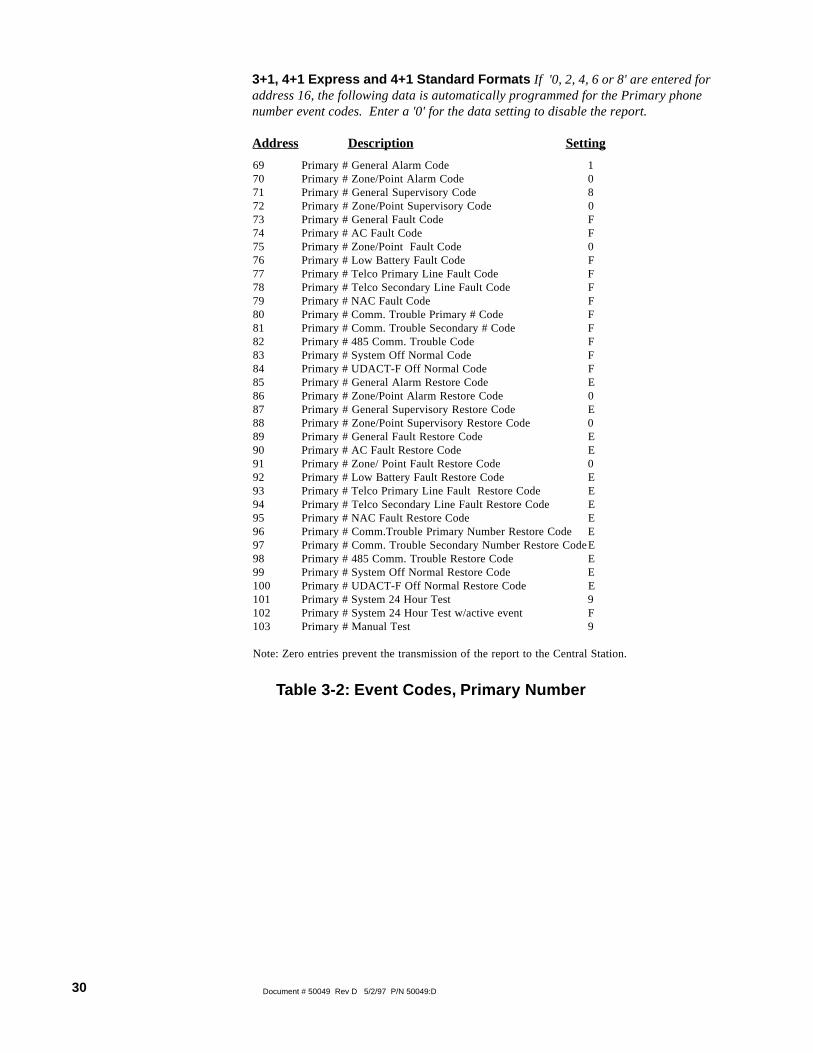
3+1, 4+1 Express and 4+1 Standard Formats If '0, 2, 4, 6 or 8' are entered foraddress 16, the following data is automatically programmed for the Primary phonenumber event codes. Enter a '0' for the data setting to disable the report.
Address Description Setting
Table 3-2: Event Codes, Primary Number
69 Primary # General Alarm Code 170 Primary # Zone/Point Alarm Code 071 Primary # General Supervisory Code 872 Primary # Zone/Point Supervisory Code 073 Primary # General Fault Code F74 Primary # AC Fault Code F75 Primary # Zone/Point Fault Code 076 Primary # Low Battery Fault Code F77 Primary # Telco Primary Line Fault Code F78 Primary # Telco Secondary Line Fault Code F79 Primary # NAC Fault Code F80 Primary # Comm. Trouble Primary # Code F81 Primary # Comm. Trouble Secondary # Code F82 Primary # 485 Comm. Trouble Code F83 Primary # System Off Normal Code F84 Primary # UDACT-F Off Normal Code F85 Primary # General Alarm Restore Code E86 Primary # Zone/Point Alarm Restore Code 087 Primary # General Supervisory Restore Code E88 Primary # Zone/Point Supervisory Restore Code 089 Primary # General Fault Restore Code E90 Primary # AC Fault Restore Code E91 Primary # Zone/ Point Fault Restore Code 092 Primary # Low Battery Fault Restore Code E93 Primary # Telco Primary Line Fault Restore Code E94 Primary # Telco Secondary Line Fault Restore Code E95 Primary # NAC Fault Restore Code E96 Primary # Comm.Trouble Primary Number Restore Code E97 Primary # Comm. Trouble Secondary Number Restore CodeE98 Primary # 485 Comm. Trouble Restore Code E99 Primary # System Off Normal Restore Code E100 Primary # UDACT-F Off Normal Restore Code E101 Primary # System 24 Hour Test 9102 Primary # System 24 Hour Test w/active event F103 Primary # Manual Test 9
Note: Zero entries prevent the transmission of the report to the Central Station.

31Document # 50049 Rev D 5/2/97 P/N 50049:D
4+2 Standard and 4+2 Express FormatsIf '1, A or C' are entered for address 16, the following data is automatically programmedfor the Primary phone number event codes. Enter a '0' for the data setting to disablethe report.
Address Description Settings
69 - 70 Primary # General Alarm Code 11 71 - 72 Primary # Zone/Point Alarm Code 00 73 - 74 Primary # General Supervisory Code 81 75 - 76 Primary # Zone/Point Supervisory Code 00 77 - 78 Primary # General Fault Code F1 79 - 80 Primary # AC Fault Code F6 81 - 82 Primary # Zone/Point Fault Code 00 83 - 84 Primary # Low Battery Fault Code F8 85 - 86 Primary # Telco Primary Line Fault Code FA 87 - 88 Primary # Telco Secondary Line Fault Code FB 89 - 90 Primary # NAC Fault Code FC 91 - 92 Primary # Comm. Trouble Primary Number Code FD 93 - 94 Primary # Comm. Trouble Secondary Number Code FE 95 - 96 Primary # 485 Comm. Trouble Code FE 97 - 98 Primary # System Off Normal Code FF 99 - 100 Primary # UDACT-F Off Normal Code FF 101 - 102 Primary # General Alarm Restore Code E1 103 - 104 Primary # Zone/Point Alarm Restore Code 00 105 - 106 Primary # General Supervisory Restore Code E2 107 - 108 Primary # Zone/Point Supervisory Restore Code 00 109 - 110 Primary # General Fault Restore Code E3 111 - 112 Primary # AC Fault Restore Code E6 113 - 114 Primary # Zone/Point Fault Restore Code 00 115 - 116 Primary # Low Battery Fault Restore Code E8 117 - 118 Primary # Telco Primary Line Fault Restore Code EA 119 - 120 Primary # Telco Secondary Line Fault Restore Code EB 121 - 122 Primary # NAC Fault Restore Code EC 123 - 124 Primary # Comm. Trouble Primary # Restore Code ED 125 - 126 Primary # Comm. Trouble Secondary # Restore Code EE 127 - 128 Primary # 485 Comm. Trouble Restore Code EE 129 - 130 Primary # System Off Normal Restore Code EF 131 - 132 Primary # UDACT-F Off Normal Restore Code EF 133 - 134 Primary # System 24 Hour Test 99 135 - 136 Primary # System 24 Hour Test w/active events 91 137 - 138 Primary # Manual Test 92
Note: Zero entries prevent the transmission of the report to the Central Station.
Table 3-3: Event Codes, Primary Number

32 Document # 50049 Rev D 5/2/97 P/N 50049:D
Address Description Setting 1 Sensor Number 69 - 71 Primary # General Alarm Code 110 000 2
72 - 74 Primary # Zone/Point Alarm Code 110 4 Note 3
75 - 77 Primary # General Supervisory Code 200 000 2
78 - 80 Primary # Zone/Point Supervisory Code 200 Note 3
81 - 83 Primary # General Fault Code 300 84 - 86 Primary # AC Fault Code 301 87 - 89 Primary # Zone/Point Fault Code 380 Note 3
90 - 92 Primary # Low Battery Fault Code 302 93 - 95 Primary # Telco Primary Line Fault Code 351 96 - 98 Primary # Telco Secondary Line Fault Code 352 99 - 101 Primary # NAC Fault Code 321 102 - 104 Primary # Comm. Trouble Primary # Code 354 105 - 107 Primary # Comm. Trouble Secondary # Code 354 108 - 110 Primary # 485 Comm. Trouble Code 300 111 - 113 Primary # System Off Normal Code 308 114 - 116 Primary # UDACT-F Off Normal Code 350 117 - 119 Primary# System 24 Hour Test 602 120 - 122 Primary # System 24 Hour Test w/active event 608 123 - 125 Primary # Manual Test Message 601
Notes:1) Note: Zero entries prevent the transmission of the report to the Central Station.2) Refer to Contact ID program locations 64 - 68.3) The identification of the zone/sensor number is automatically transmitted by the UDACT-F and is
added to the main event code. See Appendix A-3 for more information.4) Factory default for this report is 110 (110 is transmitted for modules, however, 111 will
automatically be transmitted for smoke detectors). Use Type Mode (refer to Section 4.2) to changethis report per zone or point.
Ademco Contact ID FormatIf 'E' is entered for address 16, the following data is automatically programmed for the Primaryphone number event codes. Enter a '000' for the data setting to disable the report.
Table 3-4: Ademco Contact ID, Primary Number
33Document # 50049 Rev D 5/2/97 P/N 50049:D
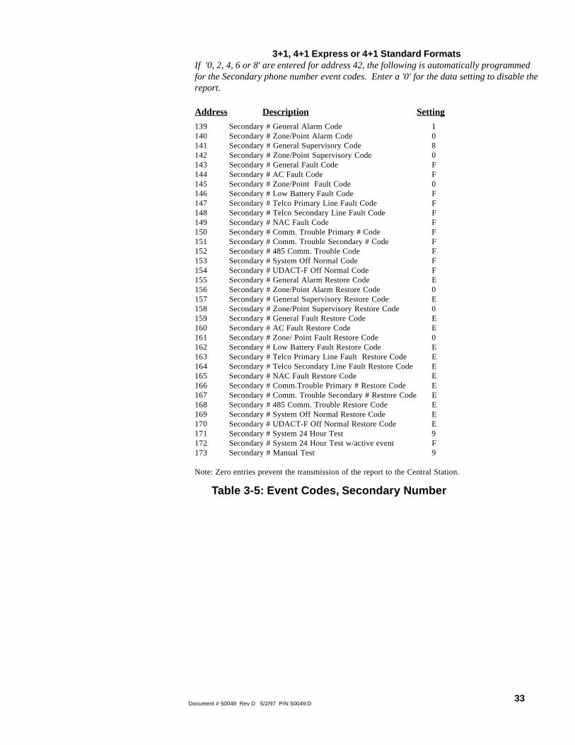
3+1, 4+1 Express or 4+1 Standard FormatsIf '0, 2, 4, 6 or 8' are entered for address 42, the following is automatically programmedfor the Secondary phone number event codes. Enter a '0' for the data setting to disable thereport.
Address Description Setting
Table 3-5: Event Codes, Secondary Number
139 Secondary # General Alarm Code 1140 Secondary # Zone/Point Alarm Code 0141 Secondary # General Supervisory Code 8142 Secondary # Zone/Point Supervisory Code 0143 Secondary # General Fault Code F144 Secondary # AC Fault Code F145 Secondary # Zone/Point Fault Code 0146 Secondary # Low Battery Fault Code F147 Secondary # Telco Primary Line Fault Code F148 Secondary # Telco Secondary Line Fault Code F149 Secondary # NAC Fault Code F150 Secondary # Comm. Trouble Primary # Code F151 Secondary # Comm. Trouble Secondary # Code F152 Secondary # 485 Comm. Trouble Code F153 Secondary # System Off Normal Code F154 Secondary # UDACT-F Off Normal Code F155 Secondary # General Alarm Restore Code E156 Secondary # Zone/Point Alarm Restore Code 0157 Secondary # General Supervisory Restore Code E158 Secondary # Zone/Point Supervisory Restore Code 0159 Secondary # General Fault Restore Code E160 Secondary # AC Fault Restore Code E161 Secondary # Zone/ Point Fault Restore Code 0162 Secondary # Low Battery Fault Restore Code E163 Secondary # Telco Primary Line Fault Restore Code E164 Secondary # Telco Secondary Line Fault Restore Code E165 Secondary # NAC Fault Restore Code E166 Secondary # Comm.Trouble Primary # Restore Code E167 Secondary # Comm. Trouble Secondary # Restore Code E168 Secondary # 485 Comm. Trouble Restore Code E169 Secondary # System Off Normal Restore Code E170 Secondary # UDACT-F Off Normal Restore Code E171 Secondary # System 24 Hour Test 9172 Secondary # System 24 Hour Test w/active event F173 Secondary # Manual Test 9
Note: Zero entries prevent the transmission of the report to the Central Station.

34 Document # 50049 Rev D 5/2/97 P/N 50049:D
4+2 Standard and 4+2 Express FormatsIf '1, A or C' are entered for address 42, the following is automatically programmedfor the Secondary phone number event codes. Enter a '0' for the data setting to disablethe report.
Address Description Setting
Table 3-6: Event Codes, Secondary Number
139 - 140 Secondary # General Alarm Code 11141 - 142 Secondary # Zone/Point Alarm Code 00143 - 144 Secondary # General Supervisory Code 81145 - 146 Secondary # Zone/Point Supervisory Code 00147 - 148 Secondary # General Fault Code F1149 - 150 Secondary # AC Fault Code F6151 - 152 Secondary # Zone/Point Fault Code 00153 - 154 Secondary # Low Battery Fault Code F8155 - 156 Secondary # Telco Primary Line Fault Code FA157 - 158 Secondary # Telco Secondary Line Fault Code FB159 - 160 Secondary # NAC Fault Code FC161 - 162 Secondary # Comm. Trouble Primary Number Code FD163 - 164 Secondary # Comm. Trouble Secondary Number Code FE165 - 166 Secondary # 485 Comm. Trouble Code FE167 - 168 Secondary # System Off Normal Code FF169 - 170 Secondary # UDACT-F Off Normal Code FF171 - 172 Secondary # General Alarm Restore Code E1173 - 174 Secondary # Zone/Point Alarm Restore Code 00175 - 176 Secondary # General Supervisory Restore Code E2177 - 178 Secondary # Zone/Point Supervisory Restore Code 00179 - 180 Secondary # General Fault Restore Code E3181 - 182 Secondary # AC Fault Restore Code E6183 - 184 Secondary # Zone/Point Fault Restore Code 00185 - 186 Secondary # Low Battery Fault Restore Code E8187 - 188 Secondary # Telco Primary Line Fault Restore Code EA189 - 190 Secondary # Telco Secondary Line Fault Restore Code EB191 - 192 Secondary # NAC Fault Restore Code EC193 - 194 Secondary # Comm. Trouble Primary # Restore Code ED195 - 196 Secondary # Comm. Trouble Secondary # Restore Code EE197 - 198 Secondary # 485 Comm. Trouble Restore Code EE199 - 200 Secondary # System Off Normal Restore Code EF201 - 202 Secondary # UDACT-F Off Normal Restore Code EF203 - 204 Secondary # System 24 Hour Test 99205 - 206 Secondary # System 24 Hour Test w/active events 91207 - 208 Secondary # Manual Test 92
Note: Zero entries prevent the transmission of the report to the Central Station.

35Document # 50049 Rev D 5/2/97 P/N 50049:D
Ademco Contact ID FormatIf 'E' is entered for address 42, the following data is automatically programmed for the Secondaryphone number event codes. Enter a '000' for the data setting to disable the report.
Address Description Setting 1 Sensor Number 139 - 141 Secondary # General Alarm Code 110 000 2
142 - 144 Secondary # Zone/Point Alarm Code 110 4 Note 3
145 - 147 Secondary # General Supervisory Code 200 000 2
148 - 150 Secondary # Zone/Point Supervisory Code 200 Note 3
151 - 153 Secondary # General Fault Code 300 154 - 156 Secondary # AC Fault Code 301 157 - 159 Secondary # Zone/Point Fault Code 380 Note 3
160 - 162 Secondary # Low Battery Fault Code 302 163 - 165 Secondary # Telco Primary Line Fault Code 351 166 - 168 Secondary # Telco Secondary Line Fault Code 352 169 - 171 Secondary # NAC Fault Code 321 172 - 174 Secondary # Comm. Trouble Primary # Code 354 175 - 177 Secondary # Comm. Trouble Secondary # Code 354 178 - 180 Secondary # 485 Comm. Trouble Code 300 181 - 183 Secondary # System Off Normal Code 308 184 - 186 Secondary # UDACT-F Off Normal Code 350 187 - 189 Secondary # System 24 Hour Test 602 190 - 192 Secondary # System 24 Hour Test w/active event 608 193 - 195 Secondary # Manual Test Message 601
Notes:1) Note: Zero entries prevent the transmission of the report to the Central Station.2) Refer to Contact ID program locations 64 - 68.3) The identification of the zone/sensor number is automatically transmitted by the UDACT-F and is
added to the main event code. See Appendix A-3 for more information.4) Factory default for this report is 110 (110 is transmitted for modules, however, 111 will automatically
be transmitted for smoke detectors). Use Type Mode (refer to Section 4.2) to change this report perzone or point.
Table 3-7: Ademco Contact ID, Secondary Number

36 Document # 50049 Rev D 5/2/97 P/N 50049:D
4.0 Operating Instructions
The UDACT-F has five Modes of operation; Normal, Type Mode, Program, LampTest, and Troubleshoot. Upon initial power up, the system will be in Normal Mode.This section discusses operation of the UDACT-F in the Normal Mode.
4.1.1 Keys : Below is a description of the function keys in Normal Mode:
The Clear function will cause the UDACT-F to:
• cease transmissions• clear any active or pending transmissions• reset and return to normal system processing
To perform the Clear function, press the Clear Key followed by 2, 5, 3, 2, then pressthe [ENTER/STORE] key.
If the Test Key is pressed three times in rapid succession the UDACT-F will transmita test message to both Central Stations. The message reported is the same as theautomatic test message for all formats except Ademco Contact ID.
Pressing the Mode Key followed by a valid 4-digit numerical code and [ENTER/STORE] selects one of the four modes of operation.
☛ To enter normal mode from any other mode press MODE then
6676 [ENTER/STORE] . 6676 spells NORM on a
Touch-Tone® phone.
CLEAR
4.1 Normal Mode
TEST
MODE

37Document # 50049 Rev D 5/2/97 P/N 50049:D
This key along with the Up Arrow and Down Arrow keys, are used to displayUDACT-F fault conditions. Press the 1st Event key at any time to display the firstevent that occurred.
Use the Down Arrow key to view other UDACT-F fault events (older) that haveoccurred and are active - not cleared yet.
Use the Up Arrow key to view other UDACT-F fault events (newer), that haveoccurred and are active - not cleared yet.
See individual mode descriptions in other sections.
4.1.2 Displays: Four 7-segment red LED characters provide visual annunciation ofUDACT-F trouble conditions. A list of messages that may appear on the display innormal mode is shown below:
1st EVENT
DOWN ARROW
UP ARROW
[ENTER/STORE]
Primary Number Communication Fault
Secondary Number Communication
Fault
Primary Phone Line Fault
Secondary Phone Line Fault
PH_1PH_2no_1no_2
Individual LEDs are provided for:
EIA-485—A yellow LED that turns on steady when a fault on the EIA-485 circuit isdetected.
Comm. Fail—This yellow LED turns on to indicate the loss of both telephone linesor that the maximum number of attempts to communicate with both Central Stationshas been unsuccessful. Note: During a comm fail, the display will show either a PH1and PH2 or no1 and no2.
Power On—A green LED that remains on while DC power is supplied to theUDACT-F. If this indicator fails to light under normal conditions, service the systemimmediately.
Kiss-Off —A green LED that blinks when the Central Station has acknowledgedreceipt of each transmitted message.
Test—A green LED that turns on to indicate that a manual test message is beingtransmitted.
Primary Line Active —A red LED that indicates the primary phone line is active.
Secondary Line Active—A red LED that indicates the secondary phone line isactive.
Modem —A green LED that stays on steady during modem types ofcommunications.

38 Document # 50049 Rev D 5/2/97 P/N 50049:D
Figure 4-1: UDACT-F Phone Connectors and LEDs
4.1.3 Normal Mode Operation: Normal mode is the standard mode of operation. Inthis mode, the UDACT-F monitors host FACP status, power input, EIA-485communications and telephone line voltage.
The four character 7-segment display is normally off and does not annunciate eventsthat are being transmitted. The display will only annunciate UDACT-F troubleconditions in the normal mode.
The UDACT-F transmits zone/point and system status reports to a Central Station viathe public switched telephone network. Two supervised telephone line connectionsare made to interface the UDACT-F to the telephone lines.
The UDACT-F supervises both telephone lines for proper voltage. A delay of twominutes will occur before a fault in either phone line connection is reported as atrouble. When a fault is detected, the 4 character display will show either 'no 1' or 'no2' (depending upon which telephone line has the fault. 'no 1' = Primary Line, 'no 2' =Secondary Line) and the trouble condition will be reported to the Central Stationover the remaining good phone line.
The UDACT-F comes with line seizure capability provided for both the primary andsecondary telephone line interfaces. Any time that the UDACT-F needs to make acall to the Central Station, line seizure will disconnect any local premises phonessharing the same telephone line.
All transmission to the Central Station will be sent over the Primary phone line. Inthe event of noisy phone lines, transmissions will be sent over the backup Secondaryphone line.
Kiss-OffLED
SecondaryActiveLED
ModemLEDPrimary Active
PrimaryLine
SecondaryLine
39Document # 50049 Rev D 5/2/97 P/N 50049:D
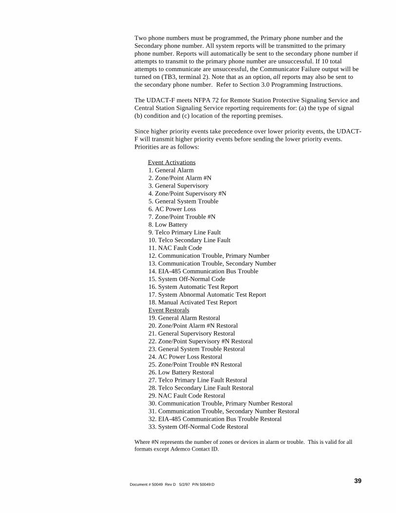
Two phone numbers must be programmed, the Primary phone number and theSecondary phone number. All system reports will be transmitted to the primaryphone number. Reports will automatically be sent to the secondary phone number ifattempts to transmit to the primary phone number are unsuccessful. If 10 totalattempts to communicate are unsuccessful, the Communicator Failure output will beturned on (TB3, terminal 2). Note that as an option, all reports may also be sent tothe secondary phone number. Refer to Section 3.0 Programming Instructions.
The UDACT-F meets NFPA 72 for Remote Station Protective Signaling Service andCentral Station Signaling Service reporting requirements for: (a) the type of signal(b) condition and (c) location of the reporting premises.
Since higher priority events take precedence over lower priority events, the UDACT-F will transmit higher priority events before sending the lower priority events.Priorities are as follows:
Event Activations1. General Alarm2. Zone/Point Alarm #N3. General Supervisory4. Zone/Point Supervisory #N5. General System Trouble6. AC Power Loss7. Zone/Point Trouble #N8. Low Battery9. Telco Primary Line Fault10. Telco Secondary Line Fault11. NAC Fault Code12. Communication Trouble, Primary Number13. Communication Trouble, Secondary Number14. EIA-485 Communication Bus Trouble15. System Off-Normal Code16. System Automatic Test Report17. System Abnormal Automatic Test Report18. Manual Activated Test ReportEvent Restorals19. General Alarm Restoral20. Zone/Point Alarm #N Restoral21. General Supervisory Restoral22. Zone/Point Supervisory #N Restoral23. General System Trouble Restoral24. AC Power Loss Restoral25. Zone/Point Trouble #N Restoral26. Low Battery Restoral27. Telco Primary Line Fault Restoral28. Telco Secondary Line Fault Restoral29. NAC Fault Code Restoral30. Communication Trouble, Primary Number Restoral31. Communication Trouble, Secondary Number Restoral32. EIA-485 Communication Bus Trouble Restoral33. System Off-Normal Code Restoral
Where #N represents the number of zones or devices in alarm or trouble. This is valid for allformats except Ademco Contact ID.

40 Document # 50049 Rev D 5/2/97 P/N 50049:D
For all formats, the 'general' reports are always transmitted (unless disabled). Thezone or point information may follow the general report if enabled.
For all pulsed formats and both Ademco Express formats, the zone/point report isrepeated per the total number of zones or points activated once factory defaultentries of zero are removed. See Tables 3-2, 3-3, 3-4, 3-5, 3-6 and 3-7. WhenAdemco Contact ID format is used, the actual zone or point activated is identifiedin the report.
The UDACT-F comes factory programmed with the reports identified above as itemnumbers 2, 4, 7, 20, 22 and 25 set to zero, preventing the reports from beingtransmitted for the pulsed and Ademco Express formats. These reports are factoryprogrammed for active transmission when using the Ademco Contact ID.
4.1.4 Key Report Descriptions
UDACT-F OFF Normal ReportRemoving the UDACT-F from Normal Mode and placing it into Program orTroubleshoot Mode causes a transmission of an 'UDACT off normal' fault message.Returning the UDACT-F to Normal Mode causes a transmission of a 'UDACT returnto normal' restoral message.
Panel OFF Normal ReportThe UDACT-F will report a "System off normal' report when the host FACPtemporarily shuts down the EIA-485 communications bus during various aspects ofsystem programming or during Walktesting. When the host FACP is returned tonormal, restoring the fire protection, the UDACT-F will report a 'system off normalrestoral' report.
System Test ReportThe UDACT-F will transmit a test message to both Central Stations at programmedintervals (typically every 24 hours). Should there exist an abnormal condition in thefire alarm system (such as an alarm, trouble or supervisory condition) at the timewhen the test report is due to be transmitted, the UDACT-F will report the 'systemabnormal test report.' If the system is normal, the report transmitted will be thenormal 'system test report.'
EIA-485 Communications Trouble ReportThe UDACT-F supervises the integrity of the information received from the FACPvia the EIA-485 communications bus. Should the communications bus malfunction,the UDACT-F transmits the report '485 comm trouble.' When the communicationsbus returns to proper operation, the UDACT-F will report '485 comm troublerestoral.'
Type mode may be used to disable reports by zone or point and to identify thespecific functionality of each zone or point in the system. Factory default for allzones/points is Fire Alarm. Use Type Mode to identify the function of each zone orpoint as follows:
• General fire alarm• Supervisory• Pull stations• Heat detectors• Waterflows• Duct detectors• Flame sensor• Smoke zone
4.2 Type Mode

41Document # 50049 Rev D 5/2/97 P/N 50049:D
To access Type Mode, press the MODE key followed by the 4-digit code 8973 andthen press the [ENTER/STORE] key. The UDACT-F will display three digits. Forexample, initial entry will display 01 0.
The characters to the left identify the zone or point number. In this example, 01identifies zone 01 or point address 01. The character to the right (0 in this example)identifies the type of zone or point as follows:
0 = Zone or point defined as fire alarm1 = Disable zone or point report2 = Zone or point defined as supervisory3 = Zone or point defined as pullstation4 = Zone or point defined as heat detector5 = Zone or point defined as waterflow6 = Zone or point defined as duct detector7 = Zone or point defined as flame sensor8 = Zone or point defined as smoke zone (Use for M302 modules
monitoring conventional smoke detectors. In point reporting,addressable detectors automatically report as detectors eliminating theneed for Type Mode entry).
Factory default is all zones or points set to 0 for fire alarm. Zone reporting allowsthe mixing of types of devices on a single zone. To change the type definition of thezone or point from the factory default, select 2 to 8 corresponding to the type ofdevice(s) used (do not mix device types for these settings), or select 1 to disablealarm reporting of any zone or point. The digit entered will appear on the far rightdisplay. Next press the [ENTER/STORE] key. This stores the entry into E2 memoryand increments to the next higher address.
Use the UP, DOWN and 1st EVENT keys to move through the list of 56 zones or198 points (refer to Appendices D & E), similar to the method described in theprogramming section of this manual. For MS-9200 applications, when address 56 isprogrammed as a 3 or 4 for point reporting, detectors are reported as points 001 to099 and modules are reported as points 101 to 199. When address 56 is programmedas a 5 or 6 for code wheel matching point reporting, detectors and modules report as001 - 099 (the actual device address).
To define all zones or points as fire alarm (return to original factory default settings)enter zone or point 999 and then press the [ENTER/STORE] key. The display willchange to 01 0, indicating a return to the factory default settings.
4.2.1 Disabling of Zones or PointsThis feature is primarily used when system points have been defined as remote reset,acknowledge, silence or drill switches. Refer to the FACP technical manual foradditional information. Activation of remote switches appear as alarms on the EIA-485 bus while in point type of annunciation. The UDACT-F will report these pointsas fire alarm points unless disabled in the Type Mode. Disabling zones or pointsalso prohibits the activation (shorted or alarm activated condition) from beingreported by the UDACT-F. Disabling of the zone or point does not affect thereporting of the zone or point trouble condition.
4.2.2 Zone or Point SupervisoryA zone or point must be defined as supervisory to allow the UDACT-F to identifythe correct report to transmit to the central station. Follow the programminginstructions in the FACP manual to program a zone or point as supervisory. Nextprogram the zone or point as a code 2 for supervisory. Use the charts in AppendicesD, E and F to enter point and zone definitions. Note that the UDACT-F fireprotection and reporting capabilities are inactive while in Type Mode.

42 Document # 50049 Rev D 5/2/97 P/N 50049:D
To get into the Troubleshoot Mode, press MODE 8768 and [ENTER/STORE] .
☛ 8768 spells TROU on a Touch-Tone® phone.
Once in this mode, the UDACT-F will:
• Transmit the 'UDACT off normal' message to the Central Station(s).• Continue to communicate any events not yet acknowledged at the Central Station prior to entering Troubleshoot Mode.
The UP Arrow key, Down Arrow key and 1st EVENT keys do not functionin this mode.
Telephone Line TestingPressing C for touchtone dialing or D for rotary dialing, followed by [ENTER/STORE] causes seizure of the Primary phone line which in turn lights the red LEDsignifying Primary phone line active. After a delay of three seconds, the UDACT-Fgoes off hook to acquire a dial tone.
The UDACT-F keypad may be used as a telephone touchpad for number dialing.Once the first digit is pressed, the display will move the C or D character oneposition to the left, while placing the digit to be dialed on the farthest right displayposition. Continue to press the phone numbers to be dialed. Successive depressionsof the [ENTER/STORE] key hangs up and picks up the phone (places the phone onor off the hook).
The secondary phone line may be tested by pressing the E key for touchtone dialingor the F key for rotary dialing and then following the same procedure used for theprimary phone line.
A handset may be temporarily connected across transformer T1 as indicated inFigure 4-2. The handset, when connected across T1, may be used only as anamplifier/speaker or telephone with the UDACT-F used for number dialing.
To perform a Lamp Test, press MODE then 5267 followed by [ENTER/STORE] .This will test all system LEDs. The LEDs will stay on for five seconds, then theUDACT-F will return to normal mode.
☛ 5267 spells LAMP on a Touch-Tone® phone.
4.3 Troubleshoot Mode
4.4 Lamp Test Mode
Figure 4-2: Handset/Speaker Connection
Both Primary andSecondary Lines

43Document # 50049 Rev D 5/2/97 P/N 50049:D
Appendix A: Reporting Formats
Table A-1 shows the data reporting structure for each of the pulsed formats as well as the AdemcoExpress formats. Ademco Express formats allow a typical data message to be transmitted to theCentral Station in under 5 seconds. Pulsed formats typically require 15 to 20 seconds incomparison. Table A-2 defines each letter code used in Table A-1. Table A-3 describes the datareporting structure used for Ademco Contact ID format.
Format #0,2, 4, 6, 8
Format #1,A, C
Report 3+1/4+1/Standard4+1 Express
4+2/Standard4+2 Express
Alarm SSS(S) A SSSS AA2
Alarm Restore SSS(S) RA SSSS RARA2
Zone Trouble(Zone Open)
SSS(S) RTZ SSSS TZTZ2
Zone Trouble Restore SSS(S) RTZ SSSS RTZRTZ2
System Trouble SSS(S) TS SSSS TSTS2
System Trouble Restore SSS(S) RTS SSSS RTSRTS2
Low Battery SSS(S) L SSSS LL2
Low Battery Restore SSS(S) RL SSSS RLRL2
AC Loss SSS(S) P SSSS PP2
AC Loss Restore SSS(S) RP SSSS RPRP2
Supervisory Condition SSS(S) V SSSS VV2
Supervisory ConditionRestore
SSS(S) RV SSSS RVRV2
Test Report SSS(S) X SSSS XX2
Abnormal Test Report SSS(S) XA SSSS XAXA2
Table A-1: Data Reporting StructureRefer to Table A-2 for an explanation of each letter code in Table A-1.Refer to Table B-1 for a list of compatible receivers.

44 Document # 50049 Rev D 5/2/97 P/N 50049:D
Where:SSS 0rSSSS = Subscriber IDA = Alarm (1st digit)A2 = Alarm (2nd digit)RA = Alarm Restore (1st digit)RA2 = Alarm Restore (2nd digit)TZ = Zone Trouble (1st digit)TZ2 = Zone Trouble (2nd digit)RTZ = Zone Trouble Restore (1st digit)RTZ2 = Zone Trouble Restore (2nd digit)TS = System Trouble (1st digit)TS2 = System Trouble (2nd digit)RTS = System Trouble Restore (1st digit)RTS2 = System Trouble Restore (2nd digit)L = Low Battery (1st digit)L2 = Low Battery (2nd digit)RL = Low Battery Restore (1st digit)RL2 = Low Battery Restore (2nd digit)P = AC Loss (1st digit)P2 = AC Loss (2nd digit)RP = AC Loss Restore (1st digit)RP2 = AC Loss Restore ( 2nd digit)V = Supervisory Condition (1st digit)V2 = Supervisory Condition (2nd digit)RV = Supervisory Condition Restore (1st digit)RV2 = Supervisory Condition Restore (2nd digit)X = Test Report (1st digit)X2 = Test Report (2nd digit)XA = Abnormal Test Report (1st digit)XA2 = Abnormal Test Report (2nd digit)
Table A-2: Letter Code Definitions (Refer to Table A-1)

45Document # 50049 Rev D 5/2/97 P/N 50049:D
The reporting structure for the Ademco Contact ID format is as follows:
SSSS 18 QXYZ GG CCC
where
SSSS = Four digit Subscriber ID (addresses 17 - 20 and 43 - 46)
18 = Identifies transmission as Contact ID to the receiver at the Central Station
Q = Event QualifierE = New EventR = New Restore
XYZ = Event code (shown in Tables 3-4 and 3-7)GG = Group number or Loop numberCCC = Zone or Sensor number
For general reports (alarm, trouble and supervisory), the GG and CCC fieldsare transmitted as 00 and 000 unless changes to addresses 64-65 and 66-68are made.
64 - 65 = Loop number (GG), (factory default is 00)66 - 68 = Sensor number (CCC) for General Alarm, Fault or
Supervisory messages (factory default is 000).
Table A-3: Ademco Contact ID Reporting Structure
A typical printout of alarm and trouble reports in the Ademco Contact IDReporting Structure follows:
Time Date SSSS QXYZ GG CCCC11:28 03/25 11 7777 E110 00 CCCC - general alarm11:28 03/25 11 7777 E110 00 C046 - alarm SD4611:28 03/25 11 7777 E300 00 CCCC - general trouble11:28 03/25 11 7777 E380 00 C046 - trouble SD4611:28 03/25 11 7777 R110 00 CCCC - general alarm restore11:28 03/25 11 7777 R110 00 C046 - alarm SD46 restore11:28 03/25 11 7777 R300 00 CCCC - general trbl restore11:28 03/25 11 7777 R380 00 C046 - trouble SD46 restore
Notes:1) In the sample report, SD46 refers to smoke detector at address 46 or on
zone 46. Refer to the charts on the following page as well as Appendi-ces D and E for further clarification.
2) 18, which is used in the reporting structure to identify the transmissionas Contact ID, is not printed out in the alarm and trouble report.
3) Q, which is the Event Qualifier for the reporting structure, is printed out inthe report as an E for New Event or R for New Restore.
Rcvr/Line ID
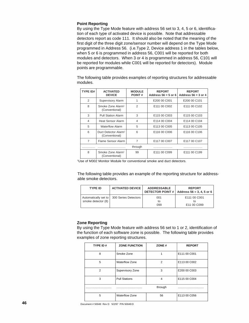
46 Document # 50049 Rev D 5/2/97 P/N 50049:D
Point ReportingBy using the Type Mode feature with address 56 set to 3, 4, 5 or 6, identifica-tion of each type of activated device is possible. Note that addressabledetectors report as code 111. It should also be noted that the meaning of thefirst digit of the three digit zone/sensor number will depend on the Type Modeprogrammed in Address 56. (i.e.Type 2, Device address 1 in the tables below,when 5 or 6 is programmed in address 56, C001 will be reported for bothmodules and detectors. When 3 or 4 is programmed in address 56, C101 willbe reported for modules while C001 will be reported for detectors). Modulepoints are programmable.
The following table provides examples of reporting structures for addressablemodules.
1Use of M302 Monitor Module for conventional smoke and duct detectors.
TYPE ID # ZONE FUNCTION ZONE # REPORT
8 Smoke Zone 1 E111 00 C001
5 Waterflow Zone 2 E113 00 C002
2 Supervisory Zone 3 E200 00 C003
3 Pull Stations 4 E115 00 C004
................................. ................................. through .................................
5 Waterflow Zone 56 E113 00 C056
Zone ReportingBy using the Type Mode feature with address 56 set to 1 or 2, identification ofthe function of each software zone is possible. The following table providesexamples of zone reporting structures.
#DIEPYT DETAVITCAECIVED
ELUDOM#TNIOP
TROPER6ro5=65sserddA
TROPER4ro3=65sserddA
2 mralAyrosivrepuS 1 100C00002E 101C00002E
8 mralAenoZekomS 1
)lanoitnevnoC(2 200C00111E 201C00111E
3 mralAnoitatSlluP 3 300C00511E 301C00511E
4 mralArosneStaeH 4 400C00411E 401C00411E
5 mralAwolfretaW 5 500C00311E 501C00311E
6 mralArotceteDtcuD 1
)lanoitnevnoC(6 600C00611E 601C00611E
7 mralArosneSemalF 7 700C00711E 701C00711E
................ .................................. hguorht ....................... .......................
8 mralAenoZekomS 1
)lanoitnevnoC(99 990C00111E 991C00111E
The following table provides an example of the reporting structure for address-able smoke detectors.
DIEPYT ECIVEDDETAVITCA ELBASSERDDA#TNIOPROTCETED
TROPER6ro5,4,3=65sserddA
ottesyllacitamotuA)8(rotcetedekoms
srotceteDseireS003 100ot990
100C00111Eot
990C0011E
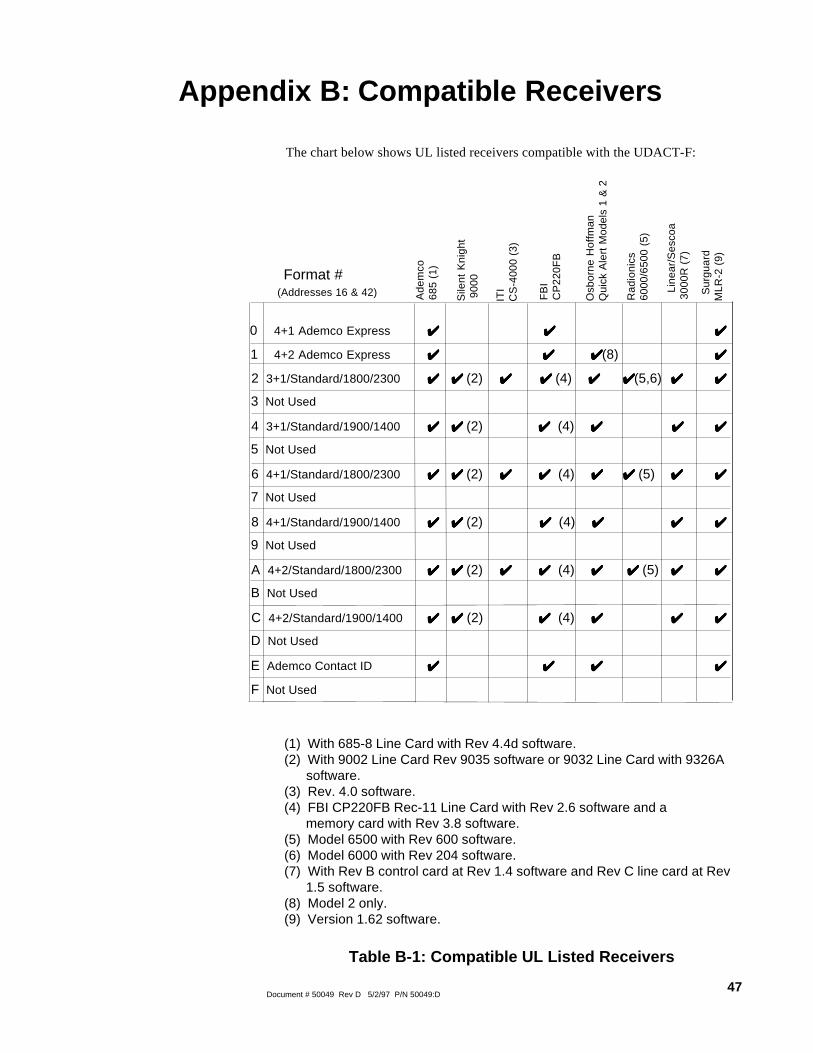
47Document # 50049 Rev D 5/2/97 P/N 50049:D
Format # (Addresses 16 & 42)
0 4+1 Ademco Express ✔✔✔✔✔ ✔ ✔ ✔ ✔ ✔ ✔✔✔✔✔
1 4+2 Ademco Express ✔✔✔✔✔ ✔ ✔ ✔ ✔ ✔ ✔ ✔ ✔ ✔ ✔(8) ✔✔✔✔✔
2 3+1/Standard/1800/2300 ✔✔✔✔✔ ✔✔✔✔✔ (2) ✔ ✔ ✔ ✔ ✔ ✔ ✔ ✔ ✔ ✔ (4) ✔ ✔ ✔ ✔ ✔ ✔ ✔ ✔ ✔ ✔(5,6) ✔ ✔ ✔ ✔ ✔ ✔✔✔✔✔
3 Not Used
4 3+1/Standard/1900/1400 ✔✔✔✔✔ ✔✔✔✔✔ (2) ✔ ✔ ✔ ✔ ✔ (4) ✔ ✔ ✔ ✔ ✔ ✔ ✔ ✔ ✔ ✔ ✔✔✔✔✔
5 Not Used
6 4+1/Standard/1800/2300 ✔✔✔✔✔ ✔✔✔✔✔ (2) ✔✔✔✔✔ ✔ ✔ ✔ ✔ ✔ (4) ✔ ✔ ✔ ✔ ✔ ✔ ✔ ✔ ✔ ✔ (5) ✔ ✔ ✔ ✔ ✔ ✔✔✔✔✔
7 Not Used
8 4+1/Standard/1900/1400 ✔✔✔✔✔ ✔✔✔✔✔ (2) ✔ ✔ ✔ ✔ ✔ (4) ✔ ✔ ✔ ✔ ✔ ✔ ✔ ✔ ✔ ✔ ✔✔✔✔✔
9 Not Used
A 4+2/Standard/1800/2300 ✔✔✔✔✔ ✔✔✔✔✔ (2) ✔✔✔✔✔ ✔ ✔ ✔ ✔ ✔ (4) ✔ ✔ ✔ ✔ ✔ ✔ ✔ ✔ ✔ ✔ (5) ✔ ✔ ✔ ✔ ✔ ✔✔✔✔✔
B Not Used
C 4+2/Standard/1900/1400 ✔✔✔✔✔ ✔ ✔ ✔ ✔ ✔ (2) ✔ ✔ ✔ ✔ ✔ (4) ✔ ✔ ✔ ✔ ✔ ✔ ✔ ✔ ✔ ✔ ✔✔✔✔✔
D Not Used
E Ademco Contact ID ✔✔✔✔✔ ✔ ✔ ✔ ✔ ✔ ✔ ✔ ✔ ✔ ✔ ✔✔✔✔✔
F Not Used
The chart below shows UL listed receivers compatible with the UDACT-F:
Ade
mco
685
(1)
Sile
nt K
nigh
t 9
000
ITI
CS
-400
0 (3
)
FB
IC
P22
0FB
Osb
orne
Hof
fman
Qui
ck A
lert
Mod
els
1 &
2
Rad
ioni
cs60
00/6
500
(5)
Li
near
/Ses
coa
3000
R (
7)
(1) With 685-8 Line Card with Rev 4.4d software.(2) With 9002 Line Card Rev 9035 software or 9032 Line Card with 9326A software.(3) Rev. 4.0 software.(4) FBI CP220FB Rec-11 Line Card with Rev 2.6 software and a memory card with Rev 3.8 software.(5) Model 6500 with Rev 600 software.(6) Model 6000 with Rev 204 software.(7) With Rev B control card at Rev 1.4 software and Rev C line card at Rev 1.5 software.(8) Model 2 only.(9) Version 1.62 software.
Table B-1: Compatible UL Listed Receivers
Appendix B: Compatible Receivers
S
urgu
ard
MLR
-2 (
9)

48 Document # 50049 Rev D 5/2/97 P/N 50049:D
Appendix C: Programming Reference Sheets--- To enter Programming, press Mode: 7 7 6 4, Enter
❑00 ❑01 ❑02 ❑03 ❑04 ❑05 ❑06 ❑07 ❑08 ❑09 ❑10 ❑11 ❑12 ❑13 ❑14 ❑15
Addresses 00 to 15 store the Primary Phone Number. Enter 'F' to represent the end of the number.
❑16 Primary Comm Format: Enter 0 - F.
❑17 ❑18 ❑19 ❑20 Primary Account Code: Valid keys are 0-F.
❑21 ❑22 ❑23 ❑24 Primary 24-Hour Test Time. Enter military time (i.e. 1400 for 2 PM).
❑25 Primary Number Test Time Interval. Enter '0' for 24-hour; '1' - 12-hour.
❑26 ❑27 ❑28 ❑29 ❑30 ❑31 ❑32 ❑33 ❑34 ❑35 ❑36 ❑37 ❑38 ❑39 ❑40 ❑41
Addresses 26-41 store the Secondary Phone Number. Enter 'F' to represent the end of the number.
❑42 Secondary Comm Format: Enter 0-F.
❑43 ❑44 ❑45 ❑46 Secondary Account Code: Valid keys are 0-F.
❑47 ❑48 ❑49 ❑50 Secondary 24-Hour Test Time. Enter military time (i.e. 1400 for 2 PM).
❑51 Secondary Number Test Time Interval. Enter '0' for 24-hour; '1' - 12-hour.
❑52 ❑53 Start Monitoring Address.
❑54 ❑55 End Monitoring Address.
❑56 UDACT-F Communication Selection. Enter '0' to disable UDACT-F communication; '1' for zone report-
ing receive only communication; '2' for zone reporting receive/transmit communication; '3' for pointreporting receive only communication; '4' for point reporting receive/transmit communication; '5' for codewheel matching point reporting, receive only; or '6' for code wheel matching point reporting, receive/transmit.
❑57 Backup Reporting. Enter '0' to have secondary phone number act as backup only; '1' to have secondary
phone number receive all reports and messages along with primary phone number.
❑58 Touchtone/Rotary Select. Enter '0' for touchtone dialing; '1' for rotary dialing.
❑59 Make/Break Ratio. If rotary dialing is selected in Address 58; Enter '0' for a 67/73 make/break ratio; '1'
for a 62/38 make/break ratio.
❑60 Leave default of 0.
❑61 Leave default of 0.
❑62 AC Loss Reporting Delay. Enter '0' for no time delay after AC loss; '1' for 6 hour delay; '2' for 7 hour
delay; '3' for 8 hour delay; '4' for 9 hour delay; '5' for 10 hour delay; '6' for 11 hour delay; '7' for 15 hourdelay; '8' for 16 hour delay; '9' for 17 hour delay; 'A' for 18 hour delay; 'B' for 19 hour delay; 'C' for 20hour delay; 'D' for 21 hour delay; 'E' for 22 hour delay; or 'F' for 23 hour delay.
❑63 Host Panel ID. Enter '0' for MS-9200; or '2' for SENSISCAN 2000; all other entries are invalid.
❑64 ❑65 Loop Number for General Reports. Factory set to '00'.
❑66 ❑67 ❑68 Sensor Number for General Reports. Factory set to '000'.

49Document # 50049 Rev D 5/2/97 P/N 50049:D
❑69 ❑70 ❑71 ❑72 ❑73 ❑74 ❑75 ❑76 ❑77 ❑78 ❑79 ❑80 ❑81
❑82
❑83
❑84
❑85
❑86
❑87
❑88
❑89
❑
90❑
91❑
92❑
93❑
94
❑95 ❑96 ❑97 ❑98 ❑99 ❑100 ❑101 ❑102 ❑103 ❑104 ❑105 ❑106 ❑107
❑108 ❑109 ❑110 ❑111 ❑112 ❑113 ❑114 ❑115 ❑116 ❑117 ❑118 ❑119 ❑120
❑121
❑122
❑123
❑124
❑125
❑126
❑127
❑128 ❑
129❑
130❑
131❑
132❑
133
❑134 ❑135 ❑136 ❑137 ❑138 ❑139 ❑140 ❑141 ❑142 ❑143 ❑144 ❑145 ❑146
❑147 ❑148 ❑149 ❑150 ❑151 ❑152 ❑153 ❑154 ❑155 ❑156 ❑157 ❑158 ❑159
❑160
❑161
❑162
❑163
❑164
❑165
❑166
❑167
❑168
❑169
❑170
❑171
❑172
❑173 ❑174 ❑175 ❑176 ❑177 ❑178 ❑179 ❑180 ❑181 ❑182 ❑183 ❑184 ❑185
❑186 ❑187 ❑188 ❑189 ❑190 ❑191 ❑192 ❑193 ❑194 ❑195 ❑196 ❑197 ❑198
❑199
❑200
❑201
❑202
❑203
❑204
❑205
❑206
❑207
❑208
Programming Reference Sheet

50 Document # 50049 Rev D 5/2/97 P/N 50049:D
Programming Reference Sheet Factory Default Settings--- To enter Programming, press Mode: 7 7 6 4, Enter
❑00 ❑01 ❑02 ❑03 ❑04 ❑05 ❑06 ❑07 ❑08 ❑09 ❑10 ❑11 ❑12 ❑13 ❑14 ❑15
Addresses 00 to 15 store the Primary Phone Number. Enter 'F' to represent the end of the number.
❑16 Primary Comm Format: (4+2 Standard 1800/2300).
❑17 ❑18 ❑19 ❑20 Primary Account Code.
❑21 ❑22 ❑23 ❑24 Primary 24-Hour Test Time. 0000 = 12:00 midnight.
❑25 Primary Number Test Time Interval. '0' for 24-hour.
❑26 ❑27 ❑28 ❑29 ❑30 ❑31 ❑32 ❑33 ❑34 ❑35 ❑36 ❑37 ❑38 ❑39 ❑40 ❑41
Addresses 26-41 store the Secondary Phone Number. Enter 'F' to represent the end of the number.
❑42 Secondary Comm Format: (4+2 Standard 1800/2300).
❑43 ❑44 ❑45 ❑46 Secondary Account Code.
❑47 ❑48 ❑49 ❑50 Secondary 24-Hour Test Time. 0000 = 12:00 midnight.
❑51 Secondary Number Test Time Interval. '0' for 24-hour.
❑52 ❑53 Start Monitoring Address
❑54 ❑55 End Monitoring Address
❑56 UDACT-F Communication Selection. '0' for UDACT-F Communication disabled.
❑57 Backup Reporting. '0' for backup.
❑58 Touchtone/Rotary Select. '0' for Touchtone.
❑59 Make/Break Ratio. '0' for 67/33 make/break ratio.
❑60 Leave default of zero.
❑61 Leave default of zero.
❑62 AC Loss reporting delay. '1' for 6 hour delay.
❑63 Host PANEL ID. '0' for MS-9200.
❑64 ❑65 Loop Number. For Ademco Contact ID, only loop number = '00',
❑66 ❑67 ❑68 Sensor Number. For Ademco Contact ID, only sensor number = '000'.
F F F F
A
0
0
F F F
0
0
0 00
000
0
0
0
0
0
0
0
0 0 0
0
F
F
A
0
0 1
1
1
0
0 0
0 0 0
F F F F F F F F F F F
FFFFFFFFFFFF
0
00

51Document # 50049 Rev D 5/2/97 P/N 50049:D
❑69 ❑70 ❑71 ❑72 ❑73 ❑74 ❑75 ❑76 ❑77 ❑78 ❑79 ❑80 ❑81
❑82
❑83
❑84
❑85
❑86
❑87
❑88
❑89 ❑
90❑
91❑
92❑
93❑
94
❑95 ❑96 ❑97 ❑98 ❑99 ❑100 ❑101 ❑102 ❑103 ❑104 ❑105 ❑106 ❑107
❑108 ❑109 ❑110 ❑111 ❑112 ❑113 ❑114 ❑115 ❑116 ❑117 ❑118 ❑119 ❑120
❑121
❑122
❑123
❑124
❑125
❑126
❑127
❑128 ❑
129❑
130❑
131❑
132❑
133
❑134 ❑135 ❑136 ❑137 ❑138 ❑139 ❑140 ❑141 ❑142 ❑143 ❑144 ❑145 ❑146
❑147 ❑148 ❑149 ❑150 ❑151 ❑152 ❑153 ❑154 ❑155 ❑156 ❑157 ❑158 ❑159
❑160
❑161
❑162
❑163
❑164
❑165
❑166
❑167
❑168
❑169
❑170
❑171
❑172
❑173 ❑174 ❑175 ❑176 ❑177 ❑178 ❑179 ❑180 ❑181 ❑182 ❑183 ❑184 ❑185
❑186 ❑187 ❑188 ❑189 ❑190 ❑191 ❑192 ❑193 ❑194 ❑195 ❑196 ❑197 ❑198
❑199
❑200
❑201
❑202
❑203
❑204
❑205
❑206
❑207
❑208
Programming Reference Sheet Factory Default
1 1 0 0 8 1 0 0 F 1 F 6 0
0 F 8 F A F B F C F D F E
F E F F F F E 1 0 0 E 2 0
0 E 3 E 6 0 0 E 8 E A E B
E C E D E E E E E EF F 9
9 9 1 9 2 1 1 0 0 18 0 0
F 1 F 6 0 0 F 8 F A F B F
C F D EF F E F F F F E 1
0 0 E 2 0 0 E 3 E 6 0 0 E
8 E A E B E C E D E E EE
FE E F 9 9 9 91 2

52 Document # 50049 Rev D 5/2/97 P/N 50049:D
Point No. Type of Device( D e t e c t o r s )
Point No. Type of Device( D e t e c t o r s )
Point No. Type of Device( M o d u l e s )
Point No. Type of Device( M o d u l e s )
0 0 1 0 5 1 1 0 1 1 5 1
0 0 2 0 5 2 1 0 2 1 5 2
0 0 3 0 5 3 1 0 3 1 5 3
0 0 4 0 5 4 1 0 4 1 5 4
0 0 5 0 5 5 1 0 5 1 5 5
0 0 6 0 5 6 1 0 6 1 5 6
0 0 7 0 5 7 1 0 7 1 5 7
0 0 8 0 5 8 1 0 8 1 5 8
0 0 9 0 5 9 1 0 9 1 5 9
0 1 0 0 6 0 1 1 0 1 6 0
0 1 1 0 6 1 1 1 1 1 6 1
0 1 2 0 6 2 1 1 2 1 6 2
0 1 3 0 6 3 1 1 3 1 6 3
0 1 4 0 6 4 1 1 4 1 6 4
0 1 5 0 6 5 1 1 5 1 6 5
0 1 6 0 6 6 1 1 6 1 6 6
0 1 7 0 6 7 1 1 7 1 6 7
0 1 8 0 6 8 1 1 8 1 6 8
0 1 9 0 6 9 1 1 9 1 6 9
0 2 0 0 7 0 1 2 0 1 7 0
0 2 1 0 7 1 1 2 1 1 7 1
0 2 2 0 7 2 1 2 2 1 7 2
0 2 3 0 7 3 1 2 3 1 7 3
0 2 4 0 7 4 1 2 4 1 7 4
0 2 5 0 7 5 1 2 5 1 7 5
0 2 6 0 7 6 1 2 6 1 7 6
0 2 7 0 7 7 1 2 7 1 7 7
0 2 8 0 7 8 1 2 8 1 7 8
0 2 9 0 7 9 1 2 9 1 7 9
0 3 0 0 8 0 1 3 0 1 8 0
0 3 1 0 8 1 1 3 1 1 8 1
0 3 2 0 8 2 1 3 2 1 8 2
0 3 3 0 8 3 1 3 3 1 8 3
0 3 4 0 8 4 1 3 4 1 8 4
0 3 5 0 8 5 1 3 5 1 8 5
0 3 6 0 8 6 1 3 6 1 8 6
0 3 7 0 8 7 1 3 7 1 8 7
0 3 8 0 8 8 1 3 8 1 8 8
0 3 9 0 8 9 1 3 9 1 8 9
0 4 0 0 9 0 1 4 0 1 9 0
0 4 1 0 9 1 1 4 1 1 9 1
0 4 2 0 9 2 1 4 2 1 9 2
0 4 3 0 9 3 1 4 3 1 9 3
0 4 4 0 9 4 1 4 4 1 9 4
0 4 5 0 9 5 1 4 5 1 9 5
0 4 6 0 9 6 1 4 6 1 9 6
0 4 7 0 9 7 1 4 7 1 9 7
0 4 8 0 9 8 1 4 8 1 9 8
0 4 9 0 9 9 1 4 9 1 9 9
0 5 0 1 5 0
Note: Use chart to carefully identify all points in the system. Leading zero in point number signifies detectors and leading onesignifies modules. Take special precaution with any supervisory points and remote switches in the system. Use Type Mode (referto Section 4.2 Type Mode) to match the function of remaining points in the system for proper reporting.
Appendix D: Point Assignments (Address 56 = 3 or 4)

53Document # 50049 Rev D 5/2/97 P/N 50049:D
Note: Use chart to carefully identify all points in the system. Take special precaution with any supervisory points and remoteswitches in the system. Use Type Mode (refer to Section 4.2 Type Mode) to match the function of remaining points in the systemfor proper reporting.
Point No. Type of Device( D e t e c t o r s )
Point No. Type of Device( D e t e c t o r s )
Point No. Type of Device( M o d u l e s )
Point No. Type of Device( M o d u l e s )
0 1 5 1 0 1 5 1
0 2 5 2 0 2 5 2
0 3 5 3 0 3 5 3
0 4 5 4 0 4 5 4
0 5 5 5 0 5 5 5
0 6 5 6 0 6 5 6
0 7 5 7 0 7 5 7
0 8 5 8 0 8 5 8
0 9 5 9 0 9 5 9
1 0 6 0 1 0 6 0
1 1 6 1 1 1 6 1
1 2 6 2 1 2 6 2
1 3 6 3 1 3 6 3
1 4 6 4 1 4 6 4
1 5 6 5 1 5 6 5
1 6 6 6 1 6 6 6
1 7 6 7 1 7 6 7
1 8 6 8 1 8 6 8
1 9 6 9 1 9 6 9
2 0 7 0 2 0 7 0
2 1 7 1 2 1 7 1
2 2 7 2 2 2 7 2
2 3 7 3 2 3 7 3
2 4 7 4 2 4 7 4
2 5 7 5 2 5 7 5
2 6 7 6 2 6 7 6
2 7 7 7 2 7 7 7
2 8 7 8 2 8 7 8
2 9 7 9 2 9 7 9
3 0 8 0 3 0 8 0
3 1 8 1 3 1 8 1
3 2 8 2 3 2 8 2
3 3 8 3 3 3 8 3
3 4 8 4 3 4 8 4
3 5 8 5 3 5 8 5
3 6 8 6 3 6 8 6
3 7 8 7 3 7 8 7
3 8 8 8 3 8 8 8
3 9 8 9 3 9 8 9
4 0 9 0 4 0 9 0
4 1 9 1 4 1 9 1
4 2 9 2 4 2 9 2
4 3 9 3 4 3 9 3
4 4 9 4 4 4 9 4
4 5 9 5 4 5 9 5
4 6 9 6 4 6 9 6
4 7 9 7 4 7 9 7
4 8 9 8 4 8 9 8
4 9 9 9 4 9 9 9
5 0 5 0
Appendix E: Code Wheel Matching Point Assignments (Address 56 = 5 or 6)

54 Document # 50049 Rev D 5/2/97 P/N 50049:D
Appendix F: Zone Assignments
Zone No. Zone Function Zone No. Zone Function
1 29
2 30
3 31
4 32
5 33
6 34
7 35
8 36
9 37
10 38
11 39
12 40
13 41
14 42
15 43
16 44
17 45
18 46
19 47
20 48
21 49
22 50
23 51
24 52
25 53
26 54
27 55
28 56
Note: Use chart to carefully identify function of each zone in the system. Take special precaution with any supervisory zones inthe system. Use Type Mode (refer to Section 4.2 Type Mode) to match the function of remaining zones in the system for properreporting.

55Document # 50049 Rev D 5/2/97 P/N 50049:D

Fire-Lite ® warrants its products to be free from defects in materials and workmanshipfor eighteen (18) months from the date of manufacture, under normal use and service.Products are date stamped at time of manufacture. The sole and exclusive obligationof Fire-Lite ® is to repair or replace, at its option, free of charge for parts and labor,any part which is defective in materials or workmanship under normal use and service.For products not under Fire-Lite ® manufacturing date-stamp control, the warranty iseighteen (18) months from date of original purchase by Fire-Lite ®'s distributor unlessthe installation instructions or catalog sets forth a shorter period, in which case theshorter period shall apply. This warranty is void if the product is altered, repaired orserviced by anyone other than Fire-Lite ® or its authorized distributors or if there is afailure to maintain the products and systems in which they operate in a proper andworkable manner. In case of defect, secure a Return Material Authorization formfrom our customer service department. Return product, transportation prepaid, toFire-Lite ®, 12 Clintonville Road, Northford, Connecticut 06472-1653.
This writing constitutes the only warranty made by Fire-Lite ® with respect to itsproducts. Fire-Lite ® does not represent that its products will prevent any loss by fireor otherwise, or that its products will in all cases provide the protection for which theyare installed or intended. Buyer acknowledges that Fire-Lite ® is not an insurer andassumes no risk for loss or damages or the cost of any inconvenience, transportation,damage, misuse, abuse, accident or similar incident.
Fire-Lite ® GIVES NO WARRANTY, EXPRESSED OR IMPLIED, OFMERCHANTABILITY, FITNESS FOR ANY PARTICULAR PURPOSE, OROTHERWISE WHICH EXTEND BEYOND THE DESCRIPTION ON THE FACEHEREOF. UNDER NO CIRCUMSTANCES SHALL Fire-Lite ® BE LIABLE FOR ANYLOSS OF OR DAMAGE TO PROPERTY, DIRECT, INCIDENTAL ORCONSEQUENTIAL, ARISING OUT OF THE USE OF, OR INABILITY TO USEFire-Lite ® PRODUCTS. FURTHERMORE, Fire-Lite ® SHALL NOT BE LIABLE FORANY PERSONAL INJURY OR DEATH WHICH MAY ARISE IN THE COURSE OF,OR AS A RESULT OF, PERSONAL, COMMERCIAL OR INDUSTRIAL USE OF ITSPRODUCTS.
This warranty replaces all previous warranties and is the only warranty made by Fire-Lite ®. No increase or alteration, written or verbal, of the obligation of this warranty isauthorized.
"Fire-Lite" is a registered trademark.
Limited Warranty
12 Clintonville Road, Northford, CT 06472Phone: (203) 484-7161FAX: (203) 484-7118
Technical Publishing Document WARFBG-C.PM6 04/02/96