the adt-udact
TRANSCRIPT

© 2000 ADT
P/N 50934:B ECN 99-402
The ADT-UDACTUniversal Digital Alarm Communicator/Transmitter
Product Information, Installation,Programming and Operation Manual
Document 50934 5/15/00 Rev: B
udac
tnot
.wm
f
One Town Center RoadBoca Raton, FL 33431Phone: (561) 988-3600FAX: (561) 988-3675
Security Services Inc.

Precau-Lg.p65 01/18/2000
An automatic fire alarm system–typically made up of smokedetectors, heat detectors, manual pull stations, audible warn-ing devices, and a fire alarm control with remote notificationcapability–can provide early warning of a developing fire.Such a system, however, does not assure protection againstproperty damage or loss of life resulting from a fire.
The Manufacturer recommends that smoke and/or heat detec-tors be located throughout a protected premise following therecommendations of the current edition of the National FireProtection Association Standard 72 (NFPA 72),manufacturer's recommendations, State and local codes, andthe recommendations contained in the Guide for Proper Useof System Smoke Detectors, which is made available at nocharge to all installing dealers. A study by the Federal Emer-gency Management Agency (an agency of the United Statesgovernment) indicated that smoke detectors may not go off inas many as 35% of all fires. While fire alarm systems are de-signed to provide early warning against fire, they do not guar-antee warning or protection against fire. A fire alarm systemmay not provide timely or adequate warning, or simply may notfunction, for a variety of reasons:
Smoke detectors may not sense fire where smoke cannotreach the detectors such as in chimneys, in or behind walls, onroofs, or on the other side of closed doors. Smoke detectorsalso may not sense a fire on another level or floor of a build-ing. A second-floor detector, for example, may not sense afirst-floor or basement fire.
Particles of combustion or "smoke" from a developing firemay not reach the sensing chambers of smoke detectors be-cause:
• Barriers such as closed or partially closed doors, walls, orchimneys may inhibit particle or smoke flow.
• Smoke particles may become "cold," stratify, and not reachthe ceiling or upper walls where detectors are located.
• Smoke particles may be blown away from detectors by airoutlets.
• Smoke detectors may be drawn into air returns beforereaching the detector.
The amount of "smoke" present may be insufficient to alarmsmoke detectors. Smoke detectors are designed to alarm atvarious levels of smoke density. If such density levels are notcreated by a developing fire at the location of detectors, thedetectors will not go into alarm.
Smoke detectors, even when working properly, have sensinglimitations. Detectors that have photoelectronic sensingchambers tend to detect smoldering fires better than flamingfires, which have little visible smoke. Detectors that have ion-izing-type sensing chambers tend to detect fast-flaming firesbetter than smoldering fires. Because fires develop in differ-ent ways and are often unpredictable in their growth, neithertype of detector is necessarily best and a given type of detec-tor may not provide adequate warning of a fire.
Smoke detectors cannot be expected to provide adequatewarning of fires caused by arson, children playing withmatches (especially in bedrooms), smoking in bed, and violentexplosions (caused by escaping gas, improper storage offlammable materials, etc.).
Heat detectors do not sense particles of combustion andalarm only when heat on their sensors increases at a prede-termined rate or reaches a predetermined level. Rate-of-riseheat detectors may be subject to reduced sensitivity over time.For this reason, the rate-of-rise feature of each detectorshould be tested at least once per year by a qualified fire pro-tection specialist. Heat detectors are designed to protectproperty, not life.
IMPORTANT! Smoke detectors must be installed in thesame room as the control panel and in rooms used by the sys-tem for the connection of alarm transmission wiring, communi-cations, signaling, and/or power. If detectors are not so lo-cated, a developing fire may damage the alarm system, crip-pling its ability to report a fire.
Audible warning devices such as bells may not alert peopleif these devices are located on the other side of closed orpartly open doors or are located on another floor of a building.Any warning device may fail to alert people with a disability orthose who have recently consumed drugs, alcohol or medica-tion. Please note that:
• Strobes can, under certain circumstances, cause seizuresin people with conditions such as epilepsy.
• Studies have shown that certain people, even when theyhear a fire alarm signal, do not respond or comprehend themeaning of the signal. It is the property owner's responsibil-ity to conduct fire drills and other training exercise to makepeople aware of fire alarm signals and instruct them on theproper reaction to alarm signals.
• In rare instances, the sounding of a warning device cancause temporary or permanent hearing loss.
A fire alarm system will not operate without any electricalpower. If AC power fails, the system will operate from standbybatteries only for a specified time and only if the batterieshave been properly maintained and replaced regularly.
Equipment used in the system may not be technically com-patible with the control. It is essential to use only equipmentlisted for service with your control panel.
Telephone lines needed to transmit alarm signals from apremise to a central monitoring station may be out of serviceor temporarily disabled. For added protection against tele-phone line failure, backup radio transmission systems are rec-ommended.
The most common cause of fire alarm malfunction is inade-quate maintenance. To keep the entire fire alarm system inexcellent working order, ongoing maintenance is required perthe manufacturer's recommendations, and UL and NFPA stan-dards. At a minimum, the requirements of Chapter 7 of NFPA72 shall be followed. Environments with large amounts ofdust, dirt or high air velocity require more frequent mainte-nance. A maintenance agreement should be arrangedthrough the local manufacturer's representative. Maintenanceshould be scheduled monthly or as required by National and/or local fire codes and should be performed by authorized pro-fessional fire alarm installers only. Adequate written recordsof all inspections should be kept.
While a fire alarm system may lower insurancerates, it is not a substitute for fire insurance!Fire Alarm System Limitations
Precau-Lg.p65 01/18/2000
WARNING - Several different sources of power can be con-nected to the fire alarm control panel. Disconnect all sourcesof power before servicing. Control unit and associated equip-ment may be damaged by removing and/or inserting cards,modules, or interconnecting cables while the unit is energized.Do not attempt to install, service, or operate this unit until thismanual is read and understood.
CAUTION - System Reacceptance Test after SoftwareChanges. To ensure proper system operation, this productmust be tested in accordance with NFPA 72 Chapter 7 afterany programming operation or change in site-specific soft-ware. Reacceptance testing is required after any change, ad-dition or deletion of system components, or after any modifica-tion, repair or adjustment to system hardware or wiring.
All components, circuits, system operations, or software func-tions known to be affected by a change must be 100% tested.In addition, to ensure that other operations are not inadvert-ently affected, at least 10% of initiating devices that are notdirectly affected by the change, up to a maximum of 50 de-vices, must also be tested and proper system operation veri-fied.
This system meets NFPA requirements for operation at0-49° C/32-120° F and at a relative humidity of 85% RH (non-condensing) at 30° C/86° F. However, the useful life of thesystem's standby batteries and the electronic componentsmay be adversely affected by extreme temperature rangesand humidity. Therefore, it is recommended that this systemand all peripherals be installed in an environment with a nomi-nal room temperature of 15-27° C/60-80° F.
Verify that wire sizes are adequate for all initiating andindicating device loops. Most devices cannot tolerate morethan a 10% I.R. drop from the specified device voltage.
Like all solid state electronic devices, this system mayoperate erratically or can be damaged when subjected to light-ning-induced transients. Although no system is completelyimmune from lightning transients and interferences, propergrounding will reduce susceptibility. Overhead or outsideaerial wiring is not recommended, due to an increased sus-ceptibility to nearby lightning strikes. Consult with the Techni-cal Services Department if any problems are anticipated orencountered.
Disconnect AC power and batteries prior to removing or in-serting circuit boards. Failure to do so can damage circuits.
Remove all electronic assemblies prior to any drilling, filing,reaming, or punching of the enclosure. When possible, makeall cable entries from the sides or rear. Before making modifi-cations, verify that they will not interfere with battery, trans-former, and printed circuit board location.
Do not tighten screw terminals more than 9 in-lbs.Over-tightening may damage threads, resulting in reducedterminal contact pressure and difficulty with screw terminalremoval.
Though designed to last many years, system componentscan fail at any time. This system contains static-sensitivecomponents. Always ground yourself with a proper wrist strapbefore handling any circuits so that static charges are re-moved from the body. Use static-suppressive packagingto protect electronic assemblies removed from the unit.
Follow the instructions in the installation, operating, andprogramming manuals. These instructions must be followedto avoid damage to the control panel and associatedequipment. FACP operation and reliability depend uponproper installation by authorized personnel.
Adherence to the following will aid in problem-freeinstallation with long-term reliability:
WARNING: This equipment generates, uses, and canradiate radio frequency energy and if not installed andused in accordance with the instruction manual, maycause interference to radio communications. It hasbeen tested and found to comply with the limits for classA computing device pursuant to Subpart B of Part 15 ofFCC Rules, which is designed to provide reasonableprotection against such interference when operated in acommercial environment. Operation of this equipment ina residential area is likely to cause interference, in whichcase the user will be required to correct the interferenceat his own expense.
Canadian RequirementsThis digital apparatus does not exceed the Class Alimits for radiation noise emissions from digitalapparatus set out in the Radio Interference Regulationsof the Canadian Department of Communications.
Le present appareil numerique n'emet pas de bruitsradioelectriques depassant les limites applicables auxappareils numeriques de la classe A prescrites dans leReglement sur le brouillage radioelectrique edicte par leministere des Communications du Canada.
FCC Warning
Installation Precautions
Document 50934 Rev B 5/15/00 PN 50934:B4
Tab
le o
f C
on
ten
tsNFPA Standards, NFPA 72 National Fire Alarm Code ................................................................... 6Underwriters Laboratories Documents ............................................................................................ 61.0 Product Description ................................................................................................................ 7
1.1 Product Features ............................................................................................................... 7Figure 1-1: ADT-UDACT Assembly ................................................................................... 8
1.2 Controls and Indicators ...................................................................................................... 91.3 Compatible Panels ............................................................................................................. 91.4 Digital Communicator ........................................................................................................ 91.5 Circuits ............................................................................................................................. 10
1.5.1 Power Requirements .............................................................................................. 101.5.2 Communications ..................................................................................................... 101.5.3 Primary and Secondary Phone Lines ..................................................................... 101.5.4 Communicator Fail Relay Driver ............................................................................ 101.5.5 Earth Ground .......................................................................................................... 10
1.6 Future Use....................................................................................................................... 101.7 Specifications ................................................................................................................... 111.8 Telephone Requirements
and Warnings ................................................................................................................... 111.8.1 Telephone Circuitry - PH1 & PH2 ......................................................................... 111.8.2 Digital Communicator: ........................................................................................... 111.8.3 Telephone Company Rights and Warnings: ........................................................ 11
1.9 Modes and Special Functions ......................................................................................... 121.9.1 Normal Mode: ......................................................................................................... 121.9.2 Program Mode: ....................................................................................................... 121.9.3 Lamp Test Mode: .................................................................................................... 121.9.4 Troubleshoot Mode: ................................................................................................ 121.9.5 Type Mode: ............................................................................................................. 121.9.6 Clear Function: ....................................................................................................... 131.9.7 Manual Test Function: ............................................................................................ 13
2.0 Installation and Wiring .......................................................................................................... 142.1 General ............................................................................................................................. 142.2 Output Circuits ................................................................................................................. 14
Figure 2-1: Wiring Phone Jacks ..................................................................................... 14Figure 2-2: Relay Driver Connections ............................................................................. 15Figure 2-3: Monitoring for ADT-UDACT Trouble ............................................................. 16
2.3 UL Power-limited Wiring Requirements ........................................................................................... 17Figure 2-4: Typical Wiring Diagram for UL Power-limited Requirements ..................... 17
3.0 Programming Instructions ................................................................................................... 183.1 Entering Program Mode ................................................................................................... 183.2 Switch Functions .............................................................................................................. 19
Figure 3-1: ADT-UDACT Keypad .................................................................................... 193.3 Programming Options ...................................................................................................... 19
Table 3-1: Start and End Monitoring Addresses ............................................................. 22Table 3-2: Event Codes, Primary Number ...................................................................... 24Table 3-3: Event Codes, Primary Number ...................................................................... 25Table 3-4: Ademco Contact ID, Primary Number ........................................................... 26Table 3-5: Event Codes, Secondary Number ................................................................. 27Table 3-6: Event Codes, Secondary Number ................................................................. 28Table 3-7: Ademco Contact ID, Secondary Number ....................................................... 29
4.0 Operating Instructions ........................................................................................................... 304.1 Normal Mode .................................................................................................................... 30
4.1.1 Keys ....................................................................................................................... 304.1.2 Displays: .................................................................................................................. 31Figure 4-1: ADT-UDACT Phone Connectors and LEDs ................................................. 324.1.3 Normal Mode Operation: ........................................................................................ 324.1.4 Key Report Descriptions ......................................................................................... 34
4.2 Type Mode ....................................................................................................................... 344.2.1 Disabling of Zones or Points .................................................................................. 354.2.2 Zone or Point Supervisory ...................................................................................... 36
4.3 Troubleshoot Mode .......................................................................................................... 36Figure 4-2: Handset/Speaker Connection ....................................................................... 37
4.4 Lamp Test Mode .............................................................................................................. 37

Document 50934 Rev B 5/15/00 PN 50934:B 5
Tab
le o
f C
on
ten
ts5.0 Reporting Formats ................................................................................................................. 38
Table 5-1: Data Reporting Structure ............................................................................... 38Table 5-2: Letter Code Definitions ................................................................................... 39Table 5-3: Ademco Contact ID Reporting Structure ....................................................... 40
6.0 Compatible Receivers ........................................................................................................... 42Table 6-1: Compatible UL Listed Receivers ................................................................... 42
7.0 Programming Reference Sheets .......................................................................................... 43Appendix A: Zone Assignments
(Unimode 300/400) ................................................................................................................ 47Appendix B: Point Assignments (Unimode 300*/400) ............................................................. 48Appendix C: Point Assignments (ADT-MNNA) ........................................................................ 51Appendix D: Unimode 2020/1010 ................................................................................................ 56
Figure D-1: ADT-UBS-1F ................................................................................................. 56Figure D-2: ADT-UDACT Mounting in CHS-4 ................................................................. 56Figure D-3: EIA-485 Connection to Panel Mounted ADT-UDACT.................................. 57Figure D-4: EIA-485 Connection to Remote ADT-UDACT ............................................. 58
Appendix E: Unimode 300/400 .................................................................................................... 59Figure E-1: ADT-ABS8RF ................................................................................................ 59Figure E-2: ADT-CPU-400 Module .................................................................................. 59Figure E-3: Unimode 400 External ADT-UDACT Mounting in ADT-ABS8RF ................ 60
Appendix F: ADT-MNNA............................................................................................................... 62Appendix G: Annunciators .......................................................................................................... 65

Document 50934 Rev B 5/15/00 PN 50934:B6
This digital communicator has been designed to comply with standards set forth by the followingregulatory agencies: • Underwriters Laboratories Standard UL 864 • NFPA Standards 72 National Fire Alarm Code for Local, Remote Station and Central Station Fire Alarm
Systems
Before proceeding, the installer should be familiar with the following documents.
NFPA Standards, NFPA 72 National Fire Alarm Code:• Central Station Fire Alarm Systems (Automatic, Manual and Waterflow) Protected Premises Unit.• Local (Automatic, Manual, Waterflow and Sprinkler Supervisory) Fire Alarm Systems.• Proprietary Fire Alarm Systems (Protected Premises Unit).• Automatic Fire Detectors• Installation, Maintenance, and Use of Notification Appliances for Fire Alarm Systems.• Inspection, Testing and Maintenance for Fire Alarm Systems.
Underwriters Laboratories Documents:UL 38 Manually Actuated Signaling BoxesUL 217 Smoke Detectors, Single and Multiple StationUL 228 Door Closers—Holders for Fire Protective Signaling SystemsUL 268 Smoke Detectors for Fire Protective Signaling SystemsUL 268A Smoke Detectors for Duct ApplicationsUL 346 Waterflow Indicators for Fire Protective Signaling SystemsUL 464 Audible Signaling AppliancesUL 521 Heat Detectors for Fire Protective Signaling SystemsUL 864 Standard for Control Units for Fire Protective Signaling SystemsUL 1481 Power Supplies for Fire Protective Signaling SystemsUL 1638 Visual Signaling Appliances
Other:NEC Article 300 Wiring MethodsNEC Article 760 Fire Protective Signaling SystemsApplicable Local and State Building CodesRequirements of the Local Authority Having Jurisdiction
Relevant ADT Manuals:
Unimode 2020/1010 manual Document #51167Unimode 300/400 Programming Document #50708Unimode 300/400 Operating Document #50709Unimode 300/400 Installation Document #50710AFM Annunciator Document #15048ADT-ACS Annunciator Document #51353ADT-LCD-80 Document #51354ADT-MNNA Document #50929
Document 50934 Rev B 5/15/00 PN 50934:B 7
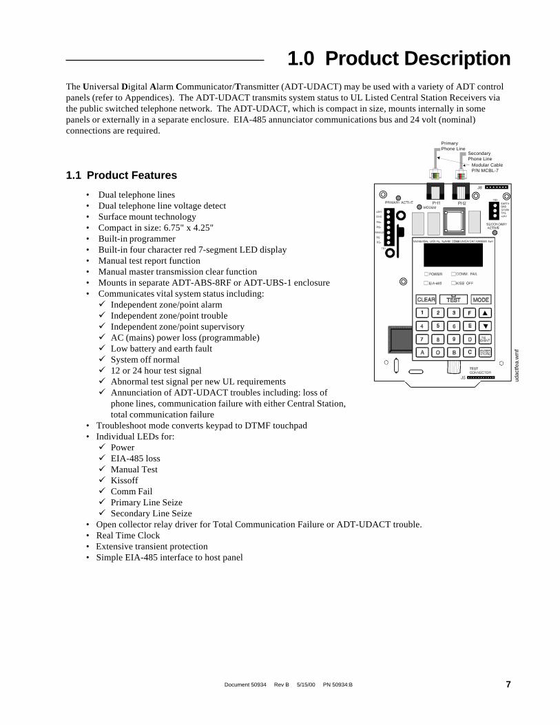
1.0 Product DescriptionThe Universal Digital Alarm Communicator/Transmitter (ADT-UDACT) may be used with a variety of ADT controlpanels (refer to Appendices). The ADT-UDACT transmits system status to UL Listed Central Station Receivers viathe public switched telephone network. The ADT-UDACT, which is compact in size, mounts internally in somepanels or externally in a separate enclosure. EIA-485 annunciator communications bus and 24 volt (nominal)connections are required.
1.1 Product Features
PrimaryPhone Line
SecondaryPhone Line
Modular CableP/N MCBL-7
• Dual telephone lines• Dual telephone line voltage detect• Surface mount technology• Compact in size: 6.75" x 4.25"• Built-in programmer• Built-in four character red 7-segment LED display• Manual test report function• Manual master transmission clear function• Mounts in separate ADT-ABS-8RF or ADT-UBS-1 enclosure• Communicates vital system status including:� Independent zone/point alarm� Independent zone/point trouble� Independent zone/point supervisory� AC (mains) power loss (programmable)� Low battery and earth fault� System off normal� 12 or 24 hour test signal� Abnormal test signal per new UL requirements� Annunciation of ADT-UDACT troubles including: loss of
phone lines, communication failure with either Central Station,total communication failure
• Troubleshoot mode converts keypad to DTMF touchpad• Individual LEDs for:� Power� EIA-485 loss� Manual Test� Kissoff� Comm Fail� Primary Line Seize� Secondary Line Seize
• Open collector relay driver for Total Communication Failure or ADT-UDACT trouble.• Real Time Clock• Extensive transient protection• Simple EIA-485 interface to host panel
udac
tfea.
wm
f

Document 50934 Rev B 5/15/00 PN 50934:B8
Figure 1-1: ADT-UDACT Assembly
PrimaryPhone Line Secondary
Phone Line
Modular CablesP/N MCBL-7(Order Separately)
24VDC Power in(use power-limitedsource)
EIA-485 Connector(use power-limitedsource)
Comm Fail Output(power-limited)
24 VDC(power-limited)
DO NOT USE
udac
tfea.
wm
f

Document 50934 Rev B 5/15/00 PN 50934:B 9
1.2 Controls andIndicators
Front Panel SwitchesCLEAR Digits 0-9TEST AMODE BUp Arrow CDown Arrow D1st EVENT EENTER/STORE F
Displays• EIA-485 - yellow LED• COMM. FAIL - yellow LED• KISS OFF - green LED• POWER - green LED• Four, Seven Segment Displays - red• Primary Phone Line Active - red LED• Secondary Phone Line Active - red LED• TEST - green LED
The ADT-UDACT has been designed to be compatible with the ADT Unimode 2020/1010, Unimode 300/400, and the ADT-MNNA.
Two modular phone jacks allow easy connection to telephone lines. Modular jacksare labeled PH1 and PH2 for the Primary and Secondary phone lines. Telephone line'Primary and Secondary Active' red LEDs are provided as well as a green 'Kissoff'LED. The integral digital communicator provides the following functions:
• Line Seizure - takes control of the phone lines disconnecting any premisesphones.
• Off/On Hook - perform on and off-hook status to the phone lines.
• Listen for dial tone - 440 hertz tone typical in most networks.
• Dialing the Central Station(s) number - default is Touch-Tone®,programmable to rotary.
Figure 1-2: Controls and Indicators
1.3 CompatiblePanels
1.4 DigitalCommunicator
DO NOTUSE
udac
tfea.
wm
f

Document 50934 Rev B 5/15/00 PN 50934:B10
• For tone burst or touchtone type formats: Discern proper 'Ack' and 'Kiss-off'tone(s) - The frequency and time duration of the tone(s) varies with thetransmission format. The ADT-UDACT will adjust accordingly.
• Communicate in the following formats (refer to Section 6.0 for compatiblereceivers):✓ 6 Tone Burst Types: 20 pps (3+1, 4+1, 4+2)✓ 3 Touchtone Types: 4 + 1 Ademco Express 4 + 2 Ademco Express Ademco Contact ID
The ADT-UDACT circuit board contains a CPU, other primary components andwiring interface connectors.
1.5.1 Power RequirementsOperating voltage for the ADT-UDACT must be power-limited, filtered,nonresettable 21.2 to 28.2 volts. The 24 VDC nominal operating power must besupplied by the Control Panel and is connected to TB1 of the ADT-UDACT.
1.5.2 CommunicationsCommunications between the ADT-UDACT and the host control panel isaccomplished over a two wire EIA-485 serial interface which is power-limited andsupervised by the control panel and the ADT-UDACT. The wiring connections aremade to the RS+, RS- and Shield terminals of TB1 on the ADT-UDACT.
The EIA-485 circuit cannot be T-Tapped and must be wired in a continuous fashionfrom the control panel to the ADT-UDACT and, if installed, annunciators. The wiremust be 12AWG to 18AWG twisted shielded pair cable with a CharacteristicImpedance of 120 Ohms, +/-20%. Limit the total wire resistance to 100 Ohms on theEIA-485 circuit. Do not run cable adjacent to, or in the same conduit as 120 voltsAC service, noisy electrical circuits that are powering mechanical bells or horns,audio circuits above 25 volts
RMS, motor control circuits, or SCR power circuits.
1.5.3 Primary and Secondary Phone LinesModular jacks are used to interface the primary and secondary phone lines to thepublic telephone network.
1.5.4 Communicator Fail Relay DriverRelay driver output for Central Station communication failure is available.
1.5.5 Earth GroundAn earth ground connection to the ADT-UDACT is required for transient protection.One option allows connection via TB3 terminal 1. A second option allowsconnection via the upper right corner mounting hole. Using a metal standoff andscrews, attach to grounded metal cabinet.
Future Use.
1.5 Circuits
1.6 Optional Device

Document 50934 Rev B 5/15/00 PN 50934:B 11
DC Power - TB1, Terminals 1 & 224VDC (nominal) filtered, nonresettable and power-limited. Voltage range is 21.2 to28.2 volts. DC Power TB1 Terminals 1 (+), 2 (-) 40 mA in standby, 75 mA max.while communicating and 100 mA with the open collector output engaged andcommunicating.
Data Communications - TB1, Terminals 3 - 7EIA-485 serial interface, TB1 Terminal 3 = RS+, 4 = RS-, 5= Shield, 6 = Future use,7 = Future use. Power-limited source must be used.
Auxiliary Output - TB3, Terminals 2 & 3TB3-2 = Communicator Failure. Power-limited circuit. An Open Collector typeoutput, normally high, active low which sinks up to 40 mA. TB3-3 = 21.2 to 28.2volts, power-limited. Use UL listed relay P/N: MR-101/C or MR-201/C with thisoutput.
Earth Ground - TB3, Terminal 1TB3-1 = Earth Ground connection. Connect this terminal to building earth groundusing solid 12 AWG wire to provide lightning protection. This connection is notrequired when the ADT-UDACT is mounted in a grounded metal enclosure via theupper right mounting hole.
1.8.1 Telephone Circuitry - PH1 & PH2Ringer Equivalence Number (REN) = 0.6BAC Impedance 10.0 Mega OhmComplies with FCC Part 68Mates with RJ31X Male ConnectorSupervision Threshold: less than 4.0 volts for 2 minutes
The REN is used to determine the quantity of devices which may be connected to thetelephone line. Excessive REN's on the telephone line may result in the devices notringing in response to an incoming call. In most, but not all areas, the sum of theREN's should not exceed five (5.0). To be certain of the number of devices that maybe connected to the line, as determined by the total REN's, contact the telephonecompany to determine the maximum REN for the calling area.
1.8.2 Digital Communicator:Before connecting the ADT-UDACT to the public switched telephone network, theinstallation of two RJ31X jacks is necessary. The following information is providedif required by the local telephone company :
Manufacturer : Notifier Fire SystemsOne Fire-Lite PlaceNorthford, CT 06472-1653
Product Model Number: ADT-UDACTFCC Registration Number: 1W6USA-20723-AL-ERinger Equivalence 0.6B
1.8.3 Telephone Company Rights and Warnings:The telephone company under certain circumstances may temporarily discontinueservices and/or make changes in its facilities, services, equipment or procedureswhich may affect the operation of this control panel. However, the telephonecompany is required to give advance notice of such changes or interruptions.
1.7 Specifications
1.8 TelephoneRequirementsand Warnings
Document 50934 Rev B 5/15/00 PN 50934:B12
If the control panel causes harm to the telephone network, the telephone companyreserves the right to temporarily discontinue service. Advance notification will beprovided except in cases when advance notice is not practical. In such cases,notification will be provided as soon as possible. The opportunity will be given tocorrect any problems and to file a complaint.
DO NOT CONNECT THIS PRODUCT TO COIN TELEPHONE, GROUND START,OR PARTY LINE SERVICES.
When the control panel activates, premise phones will be disconnected.
Two separate phone lines are required. Do not connect both telephone interfaces tothe same telephone line.
The control panel must be connected to the public switched telephone networkupstream of any private telephone system at the protected premises.
An FCC compliant telephone cord must be used with this equipment. This equipmentis designed to be connected to the telephone network or premises wiring using acompatible RJ31X male modular plug which is Part 68 compliant.
1.9.1 Normal Mode:Normal mode is the standard mode of operation. In this mode, the ADT-UDACTmonitors host FACP status as well as monitoring telephone line voltage. The ADT-UDACT reports system status information to UL listed Central Stations. Informationtransmitted includes general alarm, trouble and supervisory. It also transmits eitherthe number of zones or points activated or the specific point(s) activated, dependingupon the compatible panel, programming selections and transmission formatselection. Specific system trouble conditions and specific ADT-UDACT troubles arealso transmitted.
1.9.2 Program Mode:Program mode is used to program the ADT-UDACT. While the ADT-UDACT is inthe program mode, it cannot receive host FACP status information. See Section 3.0for complete programming instructions.
1.9.3 Lamp Test Mode:This mode turns on all segments of the 4 character display plus all LEDs on the ADT-UDACT.
1.9.4 Troubleshoot Mode:Troubleshoot mode may be used for testing the telephone line wiring. Connectionfrom the ADT-UDACT's modular jacks, through RJ31X jacks and into the telephonenetwork may be easily checked. In this mode, the keypad acts similar to a telephonetouchpad.
1.9.5 Type Mode:Type Mode is used to define the specific type of device (point) used or function of azone. Type Mode is also used to disable the alarm report for any zone/point in thesystem. The feature which disables the zone/point alarm report must be used forzones/points programmed into the host FACP as remote silence, reset, drill oracknowledge switches. Note: Unimode2020/1010 and ADT-MNNA applicationsrestrict Type Mode programming to a maximum of 568 points. All remaining pointsabove 568 will report as fire alarm points only.
1.9 Modes andSpecial Functions

Document 50934 Rev B 5/15/00 PN 50934:B 13
1.9.6 Clear Function:When the clear function is activated, it causes the ADT-UDACT to immediately stoptransmissions, hang-up from the telephone network, clear out any messages that werewaiting for transmission and reset.
1.9.7 Manual Test Function:The manual test function allows for a test report message to be sent to both CentralStations upon activation.

Document 50934 Rev B 5/15/00 PN 50934:B14
Figure 2-1: Wiring Phone Jacks
Note: Shorting barsinside RJ31X Jackremoved during maleplug insertion
7 footCable(MCBL-7)
Order Separately
Green Wire
Green Wire
Red Wire
Red Wire
To premise phonesTo premise phones
Tip
RingRing
Tip
PrimaryPhone LinePH-1
SecondaryPhone LinePH-2
Modular FemaleConnectors
Male PlugConnectors
Tip
Ring
Ring
Tip(PrimaryLines)IncomingTelco PhoneLines
(Secondary Lines)Incoming TelcoPhone Lines
Mounting OptionsFor information on mounting the ADT-UDACT in a specific fire alarm control panel,refer to the appropriate Appendix.
Telephone CircuitsProvision to connect to two independent telephone lines is available via twotelephone jacks labeled PH1 (Primary) and PH2 (Secondary). Telephone line control/command is possible via double line seizure as well as usage of an RJ31X styleinterconnection. (RJ31X jacks must be ordered separately).Note: It is critical that the ADT-UDACT be located as the first device on theincoming telephone circuit to properly function.
2.2 Output Circuits
2.1 General2.0 Installation and Wiring
UD
AC
JAK
N.W
MF
Document 50934 Rev B 5/15/00 PN 50934:B 15
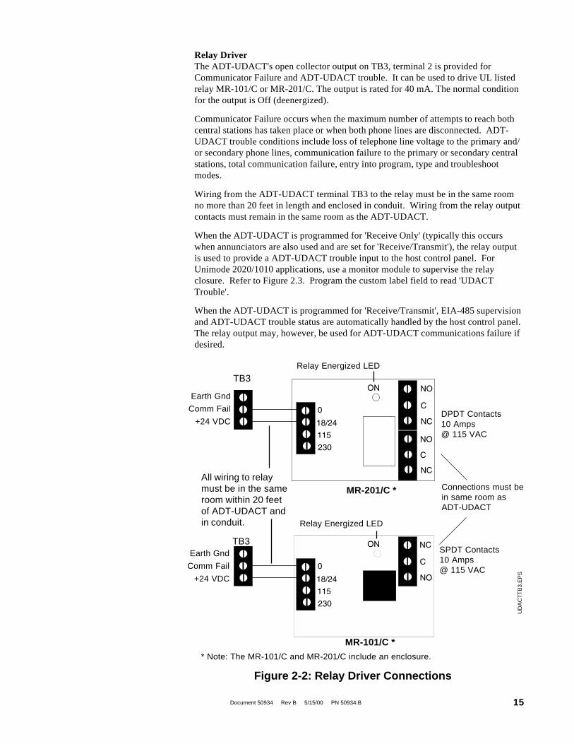
Relay DriverThe ADT-UDACT's open collector output on TB3, terminal 2 is provided forCommunicator Failure and ADT-UDACT trouble. It can be used to drive UL listedrelay MR-101/C or MR-201/C. The output is rated for 40 mA. The normal conditionfor the output is Off (deenergized).
Communicator Failure occurs when the maximum number of attempts to reach bothcentral stations has taken place or when both phone lines are disconnected. ADT-UDACT trouble conditions include loss of telephone line voltage to the primary and/or secondary phone lines, communication failure to the primary or secondary centralstations, total communication failure, entry into program, type and troubleshootmodes.
Wiring from the ADT-UDACT terminal TB3 to the relay must be in the same roomno more than 20 feet in length and enclosed in conduit. Wiring from the relay outputcontacts must remain in the same room as the ADT-UDACT.
When the ADT-UDACT is programmed for 'Receive Only' (typically this occurswhen annunciators are also used and are set for 'Receive/Transmit'), the relay outputis used to provide a ADT-UDACT trouble input to the host control panel. ForUnimode 2020/1010 applications, use a monitor module to supervise the relayclosure. Refer to Figure 2.3. Program the custom label field to read 'UDACTTrouble'.
When the ADT-UDACT is programmed for 'Receive/Transmit', EIA-485 supervisionand ADT-UDACT trouble status are automatically handled by the host control panel.The relay output may, however, be used for ADT-UDACT communications failure ifdesired.
Figure 2-2: Relay Driver Connections
Earth Gnd
Comm Fail
+24 VDC
Earth Gnd
Comm Fail
+24 VDC
TB3
TB3
* Note: The MR-101/C and MR-201/C include an enclosure.
MR-101/C *
MR-201/C *
Relay Energized LED
SPDT Contacts10 Amps@ 115 VAC
Connections must bein same room asADT-UDACT
DPDT Contacts10 Amps@ 115 VAC
Relay Energized LED
All wiring to relaymust be in the sameroom within 20 feetof ADT-UDACT andin conduit.
UD
AC
TT
B3.
EP
S
Document 50934 Rev B 5/15/00 PN 50934:B16
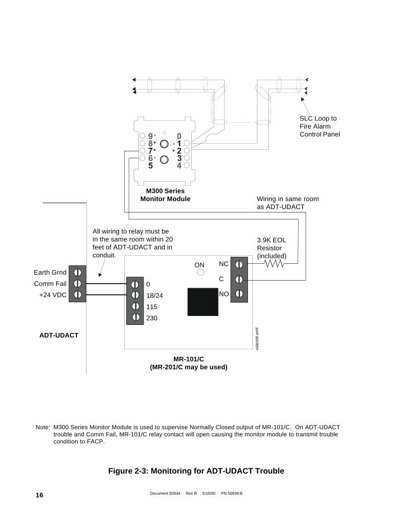
MR-101/C(MR-201/C may be used)
Note: M300 Series Monitor Module is used to supervise Normally Closed output of MR-101/C. On ADT-UDACTtrouble and Comm Fail, MR-101/C relay contact will open causing the monitor module to transmit troublecondition to FACP.
Figure 2-3: Monitoring for ADT-UDACT Trouble
udac
trbl
.wm
f
ADT-UDACT
SLC Loop toFire AlarmControl Panel
3.9K EOLResistor(included)
Wiring in same roomas ADT-UDACT
M300 SeriesMonitor Module
0
18/24
115
230
All wiring to relay must bein the same room within 20feet of ADT-UDACT and inconduit.
NC
C
NO
ONEarth Grnd
Comm Fail
+24 VDC
Document 50934 Rev B 5/15/00 PN 50934:B 17
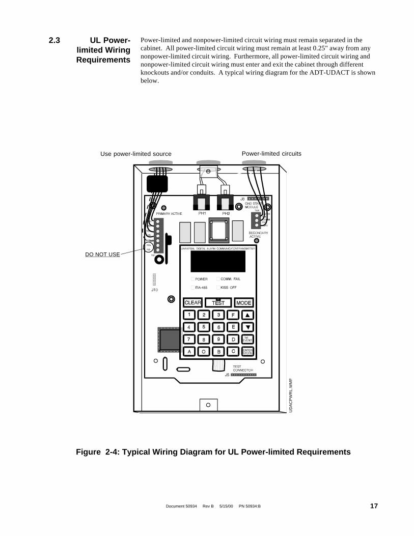
Power-limited and nonpower-limited circuit wiring must remain separated in thecabinet. All power-limited circuit wiring must remain at least 0.25" away from anynonpower-limited circuit wiring. Furthermore, all power-limited circuit wiring andnonpower-limited circuit wiring must enter and exit the cabinet through differentknockouts and/or conduits. A typical wiring diagram for the ADT-UDACT is shownbelow.
2.3 UL Power-limited WiringRequirements
Figure 2-4: Typical Wiring Diagram for UL Power-limited Requirements
Power-limited circuitsUse power-limited source
DO NOT USE
UD
AC
PW
RL.
WM
F

Document 50934 Rev B 5/15/00 PN 50934:B18
3.0 Programming Instructions
Programming Mode
___7__77_7767764
Note that as you enter information into theADT-UDACT, the digits will scroll across thedisplay from right to left
3.1 EnteringProgram Mode
You are allowed a pause of up to 10 seconds in between each number while enteringthe code. After pressing the [ENTER/STORE] key, the ADT-UDACT will be inProgram Mode and display 00_F. You are allowed up to ten minutes of idle time atthis point before starting your programming, otherwise the ADT-UDACT will goback to Normal Mode. You also have a maximum of 10 minutes between any keystroke. All entries made prior to the 10 minute time-out are valid and stored.
Once in Programming Mode, the ADT-UDACT will:• Ignore the Test and Clear keys.• Continue to communicate any events not previously acknowledged at the
Central Station prior to entering Programming Mode.
Location 56 is factory set to = 0, ADT-UDACT communications disabled. This keepsthe communicator off until location 56 is changed to 1, 2, 3 or 4. Refer to programselection for address 56 in this section. Once location 56 is changed from 0 and avalid phone number is entered, transmission of the "ADT-UDACT off Normal" reportwill occur.
Programming of the ADT-UDACT is possible at any time including while theADT-UDACT is communicating with a Central Station.
The ADT-UDACT has been designed for many different types of applications. Afterexamining your specific application, review the programming options and choose theentries best suited for your system.
The ADT-UDACT has a built-in programmer. All programming selections are storedin nonvolatile Electrically-Erasable Programmable Read-Only Memory (EEPROM).This ensures that the ADT-UDACT will retain all entries made in programming modeeven if both AC and battery power are removed.
The user must program the primary and secondary phone numbers, account numbersand 24 hour test report times for each Central Station account and the current time.The ADT-UDACT comes with factory chosen options/features already programmed.Other options/features may be programmed if desired. If all factory default settingsare acceptable, programming is complete.
To enter the Program Mode, press the MODE key once, (the display will go blank)you then have ten seconds to start entering the code (7764) .
☛ �7764�spells PROG on a Touch-Tone® phone
If an incorrect key is entered, reenter the proper 4-digit code before pressing the[ENTER/STORE] key

Document 50934 Rev B 5/15/00 PN 50934:B 19
Primary phone number. (00-15)
The first sixteen addresses, 00-15, are factory set to 'F' (from 00_F to 15_F).Programming is typically done as follows: If your phone # is 484-7161, type 4,the display will read 00_4, press [ENTER/STORE] to save the entry to memory andincrement to the next address 01_F.
Enter the remaining numbers in their respective addresses as shown below:
4 8 4 7 1 6 1 F F F F F F F F F00 01 02 03 04 05 06 07 08 09 10 11 12 13 14 15.
Valid entries for both the primary and secondary phone numbers are 0 - F with thenumeric digits as dialed numbers and hexadecimal digits (A-F) representing thefollowing functions:
A= * on a Touchtone phone keypad
B= # on a Touchtone phone keypad
C= look for secondary dial tone for up to 2 seconds (then, dial anyway)
D= 3-second pause
E= 5-second pause
F= end of phone number (Note: F must be entered)
The Function of each switch in program mode is shown below:3.2 Switch Functions
No function in this mode
3.3 ProgrammingOptions
{- Increment memory address
- Decrement memory address
- Select operating mode
Figure 3-1: ADT-UDACT Keypad
Throughout programming mode, the first three locations on the left of the displayrepresent the memory address which can range from 00 to 208 (Alpha characters arenot used). The last location (farthest right) represents the contents of the memoryaddress. The first address displayed is shown below:
00_F(address)(data)
- Once = First memory address Twice = type any address
- Save data, go to next address
Address entrykeys are 0 to 9
Data entry keysare 0 to 9 and Ato F U
DA
CT
KE
Y.W
MF

Document 50934 Rev B 5/15/00 PN 50934:B20
Primary Number Communication Format (16)One location is needed to select the Communication Format to the primary phonenumber. Address 16 is used for this purpose. The default (factory setting) for thisaddress is 16_A, which is 4+2 Standard, 1800 Hz 'Carrier', 2300 Hz 'ack'. You mayenter 0, 1, 2, 4, 6, 8, C or E in place of the default, then press [ENTER/STORE].When selecting the Format, note that Ademco Contact ID is the only format in theADT-UDACT which identifies the specific zone or point status to the Central Station.All other formats report the number of zones or points that are active but do notidentify the specific zone or point. Choose from the list of formats below:
0: 4+1 Ademco Express Standard, DTMF, 1400/2300 ACK
1: 4+2 Ademco Express Standard, DTMF, 1400/2300 ACK2: 3+1 Standard 1800 Hz Carrier, 2300 Hz ACK3: Not Used4: 3+1 Standard 1900 Hz Carrier, 1400 Hz ACK5: Not Used6: 4+1 Standard 1800 Hz Carrier, 2300 Hz ACK7: Not Used8: 4+1 Standard 1900 Hz Carrier, 1400 Hz ACK9: Not UsedA: 4+2 Standard 1800 Hz Carrier, 2300 Hz ACKB: Not UsedC: 4+2 Standard 1900 Hz Carrier, 1400 Hz ACKD: Not UsedE: Ademco Contact IDF: Not Used
Note: Consult your Central Station for proper selection or consult our factoryrepresentatives. For any format chosen, the ADT-UDACT automaticallyprograms all of the event codes. See Tables 3-2, 3-3, 3-4, 3-5, 3-6 and 3-7.
Primary Number Account Code (17-20) Four locations at addresses 17-20 default toall '0's. Valid entries are (0-9 and A-F). The number of digits entered must match theformat selection. If programming '2 or 4' into address 16, enter 3 digits. (location 20 isignored) If programming '0, 1, 6, 8, A, C, or E' into address 16, enter 4 digits.
Primary Number 24 Hour Test Time (21-24).Use military time when entering the 24 hour 'test' time. The 24 hour test report tophone number 1 takes up four locations, from addresses 21-24. The default is 00:00(12:00 midnight). The limits for each location are as follows: 21: enter 0, 1 or 2; 22:enter 0-9; 23 : enter 0-5; 24: enter 0-9. Note: Do not use A-F.
Primary Number 24/12 Hour Test Time Interval (25). The test report sent to thePrimary phone number may be sent every 12 or 24 hours. If the message is to be sentevery 24 hours, leave the factory default entry of zero. If 12 hour test report time isneeded, enter 1=12 hours.
Secondary Phone Number (26-41). Programming is similar to programming theprimary phone number located at addresses 00 - 15. The defaults are also all 'F's.
F F F F F F F F F F F F F F F F26 27 28 29 30 31 32 33 34 35 36 37 38 39 40 41.
Document 50934 Rev B 5/15/00 PN 50934:B 21
Secondary Number Communication Format (42). Programming is the same as theprimary number's Comm Format at address 16. Default entry is 'A', 4+2 Standard.When selecting the Format, note that Ademco Contact ID is the only format in theADT-UDACT which identifies the specific zone or point status to the Central Station.All other formats report the number of zones or points that are active but do not identifythe specific zone or point. Choose one entry from the list below:
0: 4+1 Ademco Express Standard, DTMF, 1400/2300 ACK1: 4+2 Ademco Express Standard, DTMF, 1400/2300 ACK2: 3+1 Standard 1800 Hz Carrier, 2300 Hz ACK3: Not Used4: 3+1 Standard 1900 Hz Carrier, 1400 Hz ACK5: Not Used6: 4+1 Standard 1800 Hz Carrier, 2300 Hz ACK7: Not Used8: 4+1 Standard 1900 Hz Carrier, 1400 Hz ACK9: Not UsedA: 4+2 Standard 1800 Hz Carrier, 2300 Hz ACKB: Not UsedC: 4+2 Standard 1900 Hz Carrier, 1400 Hz ACKD: Not UsedE: Ademco Contact IDF: Not Used
Secondary Number Account Code (43-46) is programmed in addresses 43 - 46 inthe same manner as the primary phone number Account Code. Default entries are all'0s'.
Secondary Number 24-Hour Test Time (47-50) is programmed in addresses 47-50 in the same manner as the primary number 24-Hour Test Time. Default is 00:00(12:00 midnight).
Secondary Number 24/12 Hour Test Time (51) The test message sent to theSecondary phone number may be sent every 12 or 24 hours. If the message is to besent every 24 hours, leave the factory default entry of zero. If a 12 hour test reporttime is needed, enter 1=12 hours.
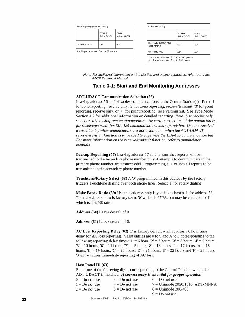
Use the Start and End Monitoring Address programming locations to set thereporting range of the ADT-UDACT.
Start Monitoring Address (52-53) is programmed to indicate the first group ofzones or points to be monitored and reported to the Central Station. Valid entries are'11 through 19' for the Unimode 300/400, and '01 through 32' for the Unimode 2020/1010 and ADT-MNNA. The factory default setting is '01'. See Table 3-1.
End Monitoring Address (54-55) is programmed to indicate the last group of zonesor points to be monitored and reported to the Central Station. Valid entries are '11through 19' for the Unimode 300/400, and '01 through 32' for the Unimode 2020/1010 and ADT-MNNA. Factory default setting is '02'.
Document 50934 Rev B 5/15/00 PN 50934:B22
Note: For additional information on the starting and ending addresses, refer to the host FACP Technical Manual.
Table 3-1: Start and End Monitoring Addresses
ADT-UDACT Communication Selection (56)Leaving address 56 at '0' disables communications to the Central Station(s). Enter '1'for zone reporting, receive only, '2' for zone reporting, receive/transmit, '3' for pointreporting, receive only, or '4' for point reporting, receive/transmit. See Type ModeSection 4.2 for additional information on detailed reporting. Note: Use receive onlyselection when using remote annunciators. Be certain to set one of the annunciatorsfor receive/transmit for EIA-485 communications bus supervision. Use the receive/transmit entry when annunciators are not installed or when the ADT-UDACTreceive/transmit function is to be used to supervise the EIA-485 communication bus.For more information on the receive/transmit function, refer to annunciatormanuals.
Backup Reporting (57) Leaving address 57 at '0' means that reports will betransmitted to the secondary phone number only if attempts to communicate to theprimary phone number are unsuccessful. Programming a '1' causes all reports to betransmitted to the secondary phone number.
Touchtone/Rotary Select (58) A '0' programmed in this address by the factorytriggers Touchtone dialing over both phone lines. Select '1' for rotary dialing.
Make Break Ratio (59) Use this address only if you have chosen '1' for address 58.The make/break ratio is factory set to '0' which is 67/33, but may be changed to '1'which is a 62/38 ratio.
Address (60) Leave default of 0.
Address (61) Leave default of 0.
AC Loss Reporting Delay (62) '1' is factory default which causes a 6 hour timedelay for AC loss reporting. Valid entries are 0 to 9 and A to F corresponding to thefollowing reporting delay times: '1' = 6 hour, '2' = 7 hours, '3' = 8 hours, '4' = 9 hours,'5' = 10 hours, '6' = 11 hours, '7' = 15 hours, '8' = 16 hours, '9' = 17 hours, 'A' = 18hours, 'B' = 19 hours, 'C' = 20 hours, 'D' = 21 hours, 'E' = 22 hours and 'F' = 23 hours.'0' entry causes immediate reporting of AC loss.
Host Panel ID (63)Enter one of the following digits corresponding to the Control Panel in which theADT-UDACT is installed. A correct entry is essential for proper operation.0 = Do not use1 = Do not use2 = Do not use
3 = Do not use4 = Do not use5 = Do not use
6 = Do not use7 = Unimode 2020/1010, ADT-MNNA8 = Unimode 300/4009 = Do not use
gnitropeRtnioP
TRATS35-25.rddA
DNE55-45.rddA
,0101/0202edominUANNM-TDA
10 2 23 2
004edominU 11 3 91 3
stniop040,2otpufosutatsstropeR=2stniop483otpufosutatsstropeR=3
)tluafeDyrotcaF(gnitropeRenoZ
TRATS35-25.rddA
DNE55-45.rddA
004edominU 11 1 21 1
senoz99otpufosutatsstropeR=1
Document 50934 Rev B 5/15/00 PN 50934:B 23
Loop Number (64 - 65)For Contact ID format only. Factory default is '00'. Maximum value is '97'. Refer toSection 5.0 for additional information.
Device/Zone Number (66 - 68)For Contact ID format only. These entries apply to the general reports only, i.e. generalalarm, general trouble, general supervisory. Factory default is '000'. Maximum value is'999'. Refer to Section 5.0 for additional information.
Note: For the Contact ID Format, Loop Number and Device Number do not directlycorrespond to the SLC Loop or Device Number, instead, it is a convenient way to transmitdata to the Central Station. Using the default Loop Number of '00' allows the reporting ofa maximum of 999 devices or zones (001-999). To report device addresses or zoneshigher than 999 (the Unimode 2020 can report up to 2,040 addresses), the Loop Numberis incremented by one to report up to an additional 1,000 device addresses or zones onthe same panel. Following is an example (using the factory defaults) of Loop Number andDevice Number settings for the ADT-UDACT on a single Unimode 2020 control panel:
Loop Number '00' reports points/zones 00 001 to 00 999Loop Number '01' reports points/zones 01 000 to 01,999Loop Number '02' reports points/zones 02 000 to 02,040
If the Loop Number (54-65) is programmed to 10, the devices are reported as:
Loop Number '10' reports points/zones 10 001 to 10 999Loop Number '11' reports points/zones 11 000 to 11,999Loop Number '12' reports points/zones 12 000 to 12,040
In applications which network multiple Fire Alarm Control Panels, the group numbermay be used to help identify each facility being monitored. For example, each ADT-UDACT can report its panel's devices by designating different Loop Numbers for eachpanel. The Loop Numbers assigned to a particular panel must be sequential, but the LoopNumbers from one panel to the next need not be sequential; i.e., the Loop Numbersassigned for the ADT-UDACT on one Unimode 2020 might be 00, 01 or 02 while theLoop Numbers for another FACP might be 10, 11 or 12 or any other set of unusedconsecutive numbers. For additional information on the Unimode 2020/1010 controlpanels, refer to Appendix D.
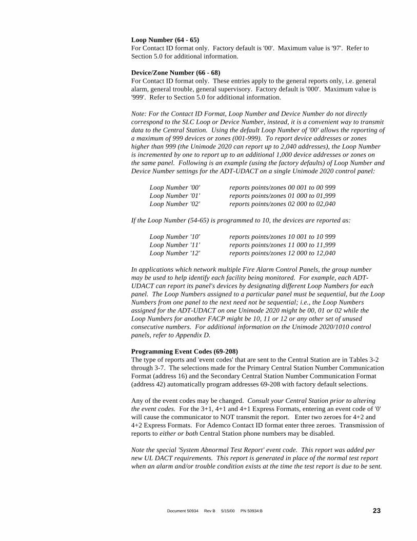
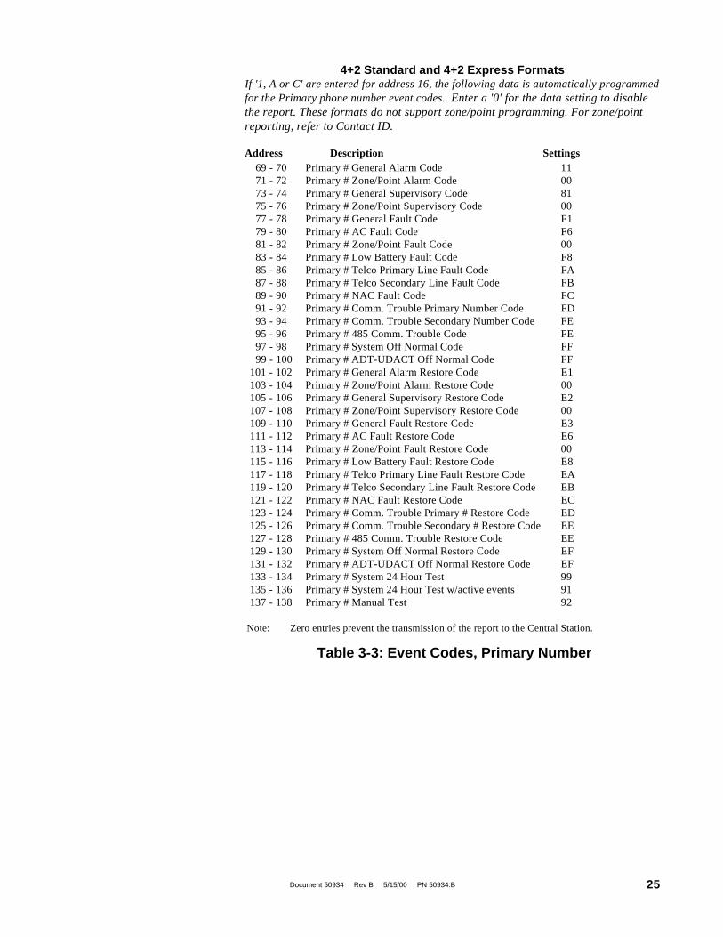
Programming Event Codes (69-208)The type of reports and 'event codes' that are sent to the Central Station are in Tables 3-2through 3-7. The selections made for the Primary Central Station Number CommunicationFormat (address 16) and the Secondary Central Station Number Communication Format(address 42) automatically program addresses 69-208 with factory default selections.
Any of the event codes may be changed. Consult your Central Station prior to alteringthe event codes. For the 3+1, 4+1 and 4+1 Express Formats, entering an event code of '0'will cause the communicator to NOT transmit the report. Enter two zeroes for 4+2 and4+2 Express Formats. For Ademco Contact ID format enter three zeroes. Transmission ofreports to either or both Central Station phone numbers may be disabled.
Note the special 'System Abnormal Test Report' event code. This report was added pernew UL DACT requirements. This report is generated in place of the normal test reportwhen an alarm and/or trouble condition exists at the time the test report is due to be sent.

Document 50934 Rev B 5/15/00 PN 50934:B24
Programming the Real-Time ClockEntering an address greater than 209 will cause a display of the current time. Oninitial power up, the clock will start running from the factory setting of 00:01(military time). The far left digit will be flashing, indicating that this is the first digitto be programmed.
Hours/MinutesSelect a digit then press [ENTER/STORE]. The digit 2nd from the left will startflashing. Select a digit then press [ENTER/STORE]. Hours setting is complete.With the digit 2nd from the right flashing, select a digit then press [ENTER/STORE]. The digit on the far right will start flashing. Select a digit then press[ENTER/STORE]. Minutes setting is complete.
End ProgrammingExit Programming Mode by pressing MODE, followed by the 4-digit codecorresponding to an alternate mode of operation, then press [ENTER/STORE].During Program Mode, if no key is pressed within 10 minutes, the ADT-UDACT willrevert to normal mode.
Table 3-2: Event Codes, Primary Number
3+1, 4+1 Express and 4+1 Standard Formats If '0, 2, 4, 6 or 8' are entered foraddress 16, the following data is automatically programmed for the Primary phonenumber event codes. Enter a '0' for the data setting to disable the report. Theseformats do not support zone/point programming. For zone/point reporting, refer toContact ID.Address Description Setting
69 Primary # General Alarm Code 170 Primary # Zone/Point Alarm Code 071 Primary # General Supervisory Code 872 Primary # Zone/Point Supervisory Code 073 Primary # General Fault Code F74 Primary # AC Fault Code F75 Primary # Zone/Point Fault Code 076 Primary # Low Battery Fault Code F77 Primary # Telco Primary Line Fault Code F78 Primary # Telco Secondary Line Fault Code F79 Primary # NAC Fault Code F80 Primary # Comm. Trouble Primary # Code F81 Primary # Comm. Trouble Secondary # Code F82 Primary # 485 Comm. Trouble Code F83 Primary # System Off Normal Code F84 Primary # ADT-UDACT Off Normal Code F85 Primary # General Alarm Restore Code E86 Primary # Zone/Point Alarm Restore Code 087 Primary # General Supervisory Restore Code E88 Primary # Zone/Point Supervisory Restore Code 089 Primary # General Fault Restore Code E90 Primary # AC Fault Restore Code E91 Primary # Zone/ Point Fault Restore Code 092 Primary # Low Battery Fault Restore Code E93 Primary # Telco Primary Line Fault Restore Code E94 Primary # Telco Secondary Line Fault Restore Code E95 Primary # NAC Fault Restore Code E96 Primary # Comm.Trouble Primary Number Restore Code E97 Primary # Comm. Trouble Secondary Number Restore Code E98 Primary # 485 Comm. Trouble Restore Code E99 Primary # System Off Normal Restore Code E100 Primary # ADT-UDACT Off Normal Restore Code E101 Primary # System 24 Hour Test 9102 Primary # System 24 Hour Test w/active event F103 Primary # Manual Test 9
Note: Zero entries prevent the transmission of the report to the Central Station.
Document 50934 Rev B 5/15/00 PN 50934:B 25
4+2 Standard and 4+2 Express FormatsIf '1, A or C' are entered for address 16, the following data is automatically programmedfor the Primary phone number event codes. Enter a '0' for the data setting to disablethe report. These formats do not support zone/point programming. For zone/pointreporting, refer to Contact ID.
Address Description Settings 69 - 70 Primary # General Alarm Code 11 71 - 72 Primary # Zone/Point Alarm Code 00 73 - 74 Primary # General Supervisory Code 81 75 - 76 Primary # Zone/Point Supervisory Code 00 77 - 78 Primary # General Fault Code F1 79 - 80 Primary # AC Fault Code F6 81 - 82 Primary # Zone/Point Fault Code 00 83 - 84 Primary # Low Battery Fault Code F8 85 - 86 Primary # Telco Primary Line Fault Code FA 87 - 88 Primary # Telco Secondary Line Fault Code FB 89 - 90 Primary # NAC Fault Code FC 91 - 92 Primary # Comm. Trouble Primary Number Code FD 93 - 94 Primary # Comm. Trouble Secondary Number Code FE 95 - 96 Primary # 485 Comm. Trouble Code FE 97 - 98 Primary # System Off Normal Code FF 99 - 100 Primary # ADT-UDACT Off Normal Code FF 101 - 102 Primary # General Alarm Restore Code E1 103 - 104 Primary # Zone/Point Alarm Restore Code 00 105 - 106 Primary # General Supervisory Restore Code E2 107 - 108 Primary # Zone/Point Supervisory Restore Code 00 109 - 110 Primary # General Fault Restore Code E3 111 - 112 Primary # AC Fault Restore Code E6 113 - 114 Primary # Zone/Point Fault Restore Code 00 115 - 116 Primary # Low Battery Fault Restore Code E8 117 - 118 Primary # Telco Primary Line Fault Restore Code EA 119 - 120 Primary # Telco Secondary Line Fault Restore Code EB 121 - 122 Primary # NAC Fault Restore Code EC 123 - 124 Primary # Comm. Trouble Primary # Restore Code ED 125 - 126 Primary # Comm. Trouble Secondary # Restore Code EE 127 - 128 Primary # 485 Comm. Trouble Restore Code EE 129 - 130 Primary # System Off Normal Restore Code EF 131 - 132 Primary # ADT-UDACT Off Normal Restore Code EF 133 - 134 Primary # System 24 Hour Test 99 135 - 136 Primary # System 24 Hour Test w/active events 91 137 - 138 Primary # Manual Test 92
Note: Zero entries prevent the transmission of the report to the Central Station.
Table 3-3: Event Codes, Primary Number
Document 50934 Rev B 5/15/00 PN 50934:B26
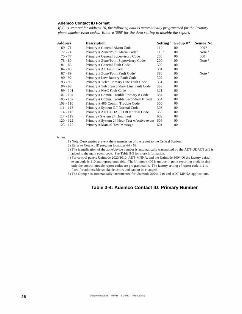
Address Description Setting 1 Group # 6 Sensor No. 69 - 71 Primary # General Alarm Code 110 00 000 2
72 - 74 Primary # Zone/Point Alarm Code5 110 4 00 Note 3
75 - 77 Primary # General Supervisory Code 200 00 000 2
78 - 80 Primary # Zone/Point Supervisory Code5 200 00 Note 3
81 - 83 Primary # General Fault Code 300 00 84 - 86 Primary # AC Fault Code 301 00 87 - 89 Primary # Zone/Point Fault Code5 380 00 Note 3
90 - 92 Primary # Low Battery Fault Code 302 00 93 - 95 Primary # Telco Primary Line Fault Code 351 00 96 - 98 Primary # Telco Secondary Line Fault Code 352 00 99 - 101 Primary # NAC Fault Code 321 00 102 - 104 Primary # Comm. Trouble Primary # Code 354 00 105 - 107 Primary # Comm. Trouble Secondary # Code 354 00 108 - 110 Primary # 485 Comm. Trouble Code 300 00 111 - 113 Primary # System Off Normal Code 308 00 114 - 116 Primary # ADT-UDACT Off Normal Code 350 00 117 - 119 Primary# System 24 Hour Test 602 00 120 - 122 Primary # System 24 Hour Test w/active event 608 00 123 - 125 Primary # Manual Test Message 601 00
Notes:1) Note: Zero entries prevent the transmission of the report to the Central Station.2) Refer to Contact ID program locations 64 - 68.3) The identification of the zone/device number is automatically transmitted by the ADT-UDACT and is
added to the main event code. See Table 5-3 for more information.4) For control panels Unimode 2020/1010, ADT-MNNA, and the Unimode 300/400 the factory default
event code is 110 and reprogrammable. The Unimode 400 is unique in point reporting mode in thatonly the control module report codes are programmable. The factory setting of report code 111 isfixed for addressable smoke detectors and cannot be changed.
5) The Group # is automatically incremented for Unimode 2020/1010 and ADT-MNNA applications.
Ademco Contact ID FormatIf 'E' is entered for address 16, the following data is automatically programmed for the Primaryphone number event codes. Enter a '000' for the data setting to disable the report.
Table 3-4: Ademco Contact ID, Primary Number
Document 50934 Rev B 5/15/00 PN 50934:B 27
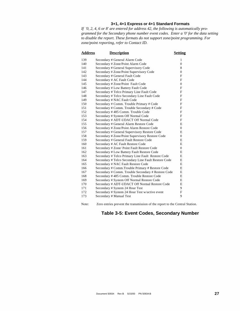
139 Secondary # General Alarm Code 1140 Secondary # Zone/Point Alarm Code 0141 Secondary # General Supervisory Code 8142 Secondary # Zone/Point Supervisory Code 0143 Secondary # General Fault Code F144 Secondary # AC Fault Code F145 Secondary # Zone/Point Fault Code 0146 Secondary # Low Battery Fault Code F147 Secondary # Telco Primary Line Fault Code F148 Secondary # Telco Secondary Line Fault Code F149 Secondary # NAC Fault Code F150 Secondary # Comm. Trouble Primary # Code F151 Secondary # Comm. Trouble Secondary # Code F152 Secondary # 485 Comm. Trouble Code F153 Secondary # System Off Normal Code F154 Secondary # ADT-UDACT Off Normal Code F155 Secondary # General Alarm Restore Code E156 Secondary # Zone/Point Alarm Restore Code 0157 Secondary # General Supervisory Restore Code E158 Secondary # Zone/Point Supervisory Restore Code 0159 Secondary # General Fault Restore Code E160 Secondary # AC Fault Restore Code E161 Secondary # Zone/ Point Fault Restore Code 0162 Secondary # Low Battery Fault Restore Code E163 Secondary # Telco Primary Line Fault Restore Code E164 Secondary # Telco Secondary Line Fault Restore Code E165 Secondary # NAC Fault Restore Code E166 Secondary # Comm.Trouble Primary # Restore Code E167 Secondary # Comm. Trouble Secondary # Restore Code E168 Secondary # 485 Comm. Trouble Restore Code E169 Secondary # System Off Normal Restore Code E170 Secondary # ADT-UDACT Off Normal Restore Code E171 Secondary # System 24 Hour Test 9172 Secondary # System 24 Hour Test w/active event F173 Secondary # Manual Test 9
Note: Zero entries prevent the transmission of the report to the Central Station.
Table 3-5: Event Codes, Secondary Number
3+1, 4+1 Express or 4+1 Standard FormatsIf '0, 2, 4, 6 or 8' are entered for address 42, the following is automatically pro-grammed for the Secondary phone number event codes. Enter a '0' for the data settingto disable the report. These formats do not support zone/point programming. Forzone/point reporting, refer to Contact ID.
Address Description Setting
Document 50934 Rev B 5/15/00 PN 50934:B28
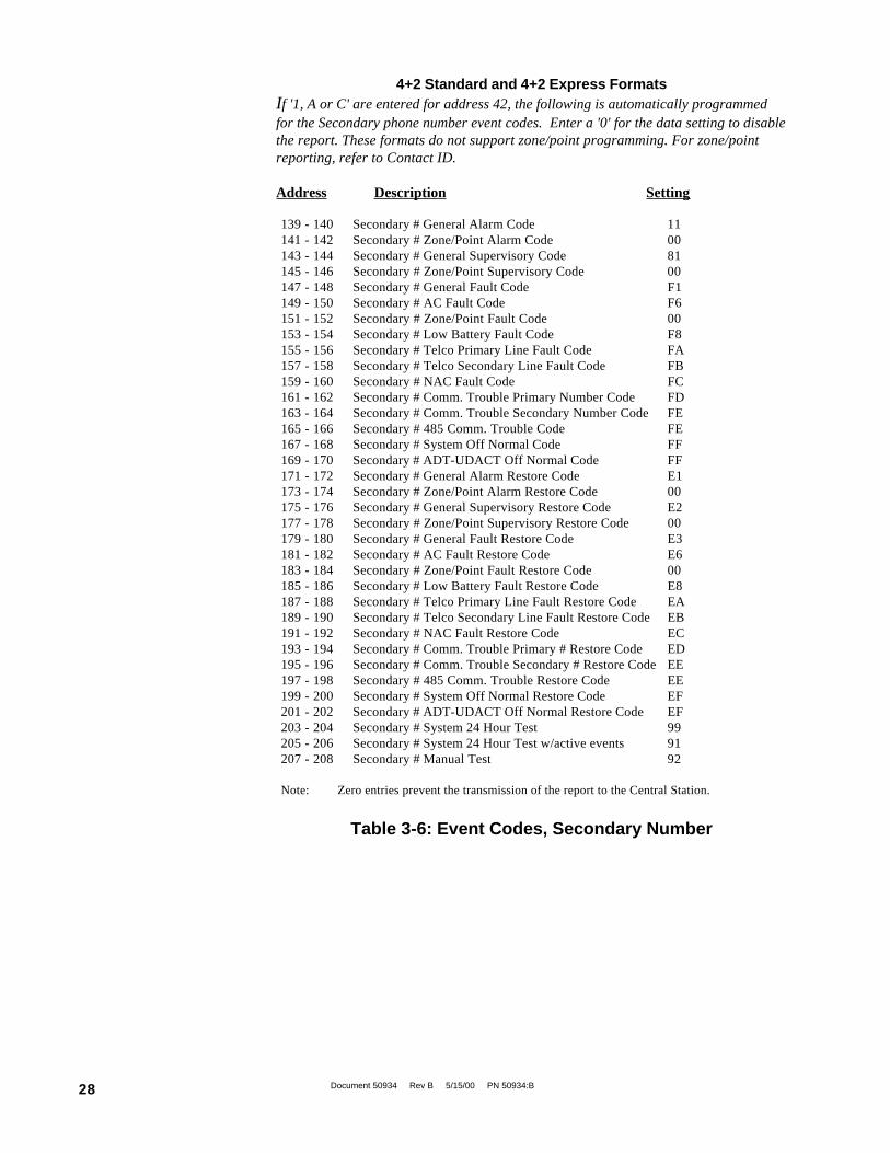
4+2 Standard and 4+2 Express FormatsIf '1, A or C' are entered for address 42, the following is automatically programmedfor the Secondary phone number event codes. Enter a '0' for the data setting to disablethe report. These formats do not support zone/point programming. For zone/pointreporting, refer to Contact ID.
Address Description Setting
Table 3-6: Event Codes, Secondary Number
139 - 140 Secondary # General Alarm Code 11141 - 142 Secondary # Zone/Point Alarm Code 00143 - 144 Secondary # General Supervisory Code 81145 - 146 Secondary # Zone/Point Supervisory Code 00147 - 148 Secondary # General Fault Code F1149 - 150 Secondary # AC Fault Code F6151 - 152 Secondary # Zone/Point Fault Code 00153 - 154 Secondary # Low Battery Fault Code F8155 - 156 Secondary # Telco Primary Line Fault Code FA157 - 158 Secondary # Telco Secondary Line Fault Code FB159 - 160 Secondary # NAC Fault Code FC161 - 162 Secondary # Comm. Trouble Primary Number Code FD163 - 164 Secondary # Comm. Trouble Secondary Number Code FE165 - 166 Secondary # 485 Comm. Trouble Code FE167 - 168 Secondary # System Off Normal Code FF169 - 170 Secondary # ADT-UDACT Off Normal Code FF171 - 172 Secondary # General Alarm Restore Code E1173 - 174 Secondary # Zone/Point Alarm Restore Code 00175 - 176 Secondary # General Supervisory Restore Code E2177 - 178 Secondary # Zone/Point Supervisory Restore Code 00179 - 180 Secondary # General Fault Restore Code E3181 - 182 Secondary # AC Fault Restore Code E6183 - 184 Secondary # Zone/Point Fault Restore Code 00185 - 186 Secondary # Low Battery Fault Restore Code E8187 - 188 Secondary # Telco Primary Line Fault Restore Code EA189 - 190 Secondary # Telco Secondary Line Fault Restore Code EB191 - 192 Secondary # NAC Fault Restore Code EC193 - 194 Secondary # Comm. Trouble Primary # Restore Code ED195 - 196 Secondary # Comm. Trouble Secondary # Restore Code EE197 - 198 Secondary # 485 Comm. Trouble Restore Code EE199 - 200 Secondary # System Off Normal Restore Code EF201 - 202 Secondary # ADT-UDACT Off Normal Restore Code EF203 - 204 Secondary # System 24 Hour Test 99205 - 206 Secondary # System 24 Hour Test w/active events 91207 - 208 Secondary # Manual Test 92
Note: Zero entries prevent the transmission of the report to the Central Station.

Document 50934 Rev B 5/15/00 PN 50934:B 29
Ademco Contact ID FormatIf 'E' is entered for address 42, the following data is automatically programmed for the Secondaryphone number event codes. Enter a '000' for the data setting to disable the report.
Address Description Setting 1 Group # 6 Sensor No. 139 - 141 Secondary # General Alarm Code 110 00 000 2
142 - 144 Secondary # Zone/Point Alarm Code 110 4 00 Note 3
145 - 147 Secondary # General Supervisory Code 200 00 000 2
148 - 150 Secondary # Zone/Point Supervisory Code 200 00 Note 3
151 - 153 Secondary # General Fault Code 300 00 154 - 156 Secondary # AC Fault Code 301 00 157 - 159 Secondary # Zone/Point Fault Code 380 00 Note 3
160 - 162 Secondary # Low Battery Fault Code 302 00 163 - 165 Secondary # Telco Primary Line Fault Code 351 00 166 - 168 Secondary # Telco Secondary Line Fault Code 352 00 169 - 171 Secondary # NAC Fault Code 321 00 172 - 174 Secondary # Comm. Trouble Primary # Code 354 00 175 - 177 Secondary # Comm. Trouble Secondary # Code 354 00 178 - 180 Secondary # 485 Comm. Trouble Code 300 00 181 - 183 Secondary # System Off Normal Code 308 00 184 - 186 Secondary # ADT-UDACT Off Normal Code 350 00 187 - 189 Secondary # System 24 Hour Test 602 00 190 - 192 Secondary # System 24 Hour Test w/active event 608 00 193 - 195 Secondary # Manual Test Message 601 00
Notes:1) Note: Zero entries prevent the transmission of the report to the Central Station.2) Refer to Contact ID program locations 64 - 68.3) The identification of the zone/device number is automatically transmitted by the ADT-UDACT and is
added to the main event code. See Table 5-3 for more information.4) For control panels Unimode 2020/1010, ADT-MNNA, and Unimode 300/400 the factory default event
code is 110 and reprogrammable. The Unimode 300 and Unimode 400 are unique in point reportingmode in that only the control module report codes are programmable. The factory setting of reportcode 111 is fixed for addressable smoke detectors and cannot be changed.
5) The Group # is automatically incremented for Unimode 2020/1010 and ADT-MNNA applications.
Table 3-7: Ademco Contact ID, Secondary Number

Document 50934 Rev B 5/15/00 PN 50934:B30
4.0 Operating Instructions
The ADT-UDACT has five Modes of operation; Normal, Program, Lamp Test,Troubleshoot and Type mode. Upon initial power up, the system will be in NormalMode. This section discusses operation of the ADT-UDACT in the Normal Mode.
4.1.1 KeysBelow is a description of the function keys in Normal Mode:
The Clear function will cause the ADT-UDACT to:
• cease transmissions• clear any active or pending transmissions• reset and return to normal system processing
To perform the Clear function, press the Clear Key followed by 2, 5, 3, 2, then pressthe [ENTER/STORE] key.
If the Test Key is pressed three times in rapid succession the ADT-UDACT willtransmit a test message to both Central Stations. The message reported is the same asthe automatic test message for all formats except Ademco Contact ID.
Pressing the Mode Key followed by a valid 4-digit numerical code and [ENTER/STORE] selects one of the four modes of operation.
☛ To enter normal mode from any other mode press MODE then
6676 [ENTER/STORE]. 6676 spells NORM on a Touch-Tone® phone.
CLEAR
4.1 Normal Mode
TEST
MODE
UD
AC
TK
EY
.WM
F

Document 50934 Rev B 5/15/00 PN 50934:B 31
This key along with the Up Arrow and Down Arrow keys, are used to display ADT-UDACT fault conditions. Press the 1st Event key at any time to display the first eventthat occurred.
Use the Down Arrow key to view other ADT-UDACT fault events (older) that haveoccurred and are active - not cleared yet.
Use the Up Arrow key to view other ADT-UDACT fault events (newer), that haveoccurred and are active - not cleared yet.
See individual mode descriptions in other sections.
4.1.2 Displays:Four 7-segment red LED characters provide visual annunciation of ADT-UDACTtrouble conditions. A list of messages that may appear on the display in normal modeis shown below:
1st EVENT
DOWN ARROW
UP ARROW
[ENTER/STORE]
Primary Number Communication Fault
Secondary Number Communication Fault
Primary Phone Line Fault
Secondary Phone Line Fault
PH_1PH_2no_1no_2
Individual LEDs are provided for:
EIA-485—A yellow LED that turns on steady when a fault on the EIA-485 circuit isdetected.
Comm. Fail—This yellow LED turns on to indicate the loss of both telephone linesor that the maximum number of attempts to communicate with both Central Stationshas been unsuccessful. Note: During a comm fail, the display will show either a PH1and PH2 or no1 and no2.
Power On—A green LED that remains on while DC power is supplied to the ADT-UDACT. If this indicator fails to light under normal conditions, service the systemimmediately.
Kiss-Off —A green LED that blinks when the Central Station has acknowledgedreceipt of each transmitted message.
Test—A green LED that turns on to indicate that a manual test message is beingtransmitted.
Primary Line Active—A red LED that indicates the primary phone line is active.
Secondary Line Active—A red LED that indicates the secondary phone line isactive.
Modem —A green LED that stays on steady during modem types ofcommunications.

Document 50934 Rev B 5/15/00 PN 50934:B32
Primary Active
PrimaryLine
SecondaryLine
SecondaryActiveLED
Kiss-OffLED
ModemLED
Figure 4-1: ADT-UDACT Phone Connectors and LEDs
4.1.3 Normal Mode Operation:Normal mode is the standard mode of operation. In this mode, the ADT-UDACTmonitors host FACP status, power input, EIA-485 communications and telephone linevoltage.
The four character 7-segment display is normally off and does not annunciate eventsthat are being transmitted. The display will only annunciate ADT-UDACT troubleconditions in the normal mode.
The ADT-UDACT transmits zone/point and system status reports to a Central Stationvia the public switched telephone network. Two supervised telephone lineconnections are made to interface the ADT-UDACT to the telephone lines.
The ADT-UDACT supervises both telephone lines for proper voltage. A delay of twominutes will occur before a fault in either phone line connection is reported as atrouble. When a fault is detected, the 4 character display will show either 'no 1' or'no 2' (depending upon which telephone line has the fault. 'no 1' = Primary Line, 'no 2'= Secondary Line) and the trouble condition will be reported to the Central Stationover the remaining good phone line.
The ADT-UDACT comes with line seizure capability provided for both the primaryand secondary telephone line interfaces. Any time that the ADT-UDACT needs tomake a call to the Central Station, line seizure will disconnect any local premisesphones sharing the same telephone line.
All transmission to the Central Station will be sent over the Primary phone line. In theevent of noisy phone lines, transmissions will be sent over the backup Secondaryphone line.
UD
AC
TN
OT
.WM
F

Document 50934 Rev B 5/15/00 PN 50934:B 33
Two phone numbers must be programmed, the Primary phone number and theSecondary phone number. All system reports will be transmitted to the primary phonenumber. Reports will automatically be sent to the secondary phone number if attemptsto transmit to the primary phone number are unsuccessful. If 10 total attempts tocommunicate are unsuccessful, the Communicator Failure output will be turned on(TB3, terminal 2). Note that as an option, all reports may also be sent to thesecondary phone number. Refer to Section 3.0 Programming Instructions.
The ADT-UDACT meets NFPA 72 for Remote Station Protective Signaling Serviceand Central Station Signaling Service reporting requirements for: (a) the type ofsignal (b) condition and (c) location of the reporting premises.
Since higher priority events take precedence over lower priority events, the ADT-UDACT will transmit higher priority events before sending the lower priority events.Priorities are as follows:
Event Activations1. General Alarm2. Zone/Point Alarm #N3. General Supervisory4. Zone/Point Supervisory #N5. General System Trouble6. AC Power Loss7. Zone/Point Trouble #N8. Low Battery9. Telco Primary Line Fault10. Telco Secondary Line Fault11. NAC Fault Code12. Communication Trouble, Primary Number13. Communication Trouble, Secondary Number14. EIA-485 Communication Bus Trouble15. System Off-Normal Code16. System Automatic Test Report17. System Abnormal Automatic Test Report18. Manual Activated Test ReportEvent Restorals19. General Alarm Restoral20. Zone/Point Alarm #N Restoral21. General Supervisory Restoral22. Zone/Point Supervisory #N Restoral23. General System Trouble Restoral24. AC Power Loss Restoral25. Zone/Point Trouble #N Restoral26. Low Battery Restoral27. Telco Primary Line Fault Restoral28. Telco Secondary Line Fault Restoral29. NAC Fault Code Restoral30. Communication Trouble, Primary Number Restoral31. Communication Trouble, Secondary Number Restoral32. EIA-485 Communication Bus Trouble Restoral33. System Off-Normal Code Restoral
Where #N represents the number of zones or devices in alarm or trouble. This is validfor all formats except Ademco Contact ID.
For all formats, the 'general' reports are always transmitted (unless disabled). Thezone or point information may follow the general report if enabled.

Document 50934 Rev B 5/15/00 PN 50934:B34
For all pulsed formats and both Ademco Express formats, the zone/point report isrepeated per the total number of zones or points activated once factory default entriesof zero are removed. See Tables 3-2, 3-3, 3-4, 3-5, 3-6 and 3-7. When Ademco ContactID format is used, the actual zone or point activated is identified in the report.
The ADT-UDACT comes factory programmed with the reports identified above as itemnumbers 2, 4, 7, 20, 22 and 25 set to zero, preventing the reports from being transmittedfor the pulsed and Ademco Express formats. These reports are factory programmed foractive transmission when using the Ademco Contact ID.
4.1.4 Key Report Descriptions
ADT-UDACT OFF Normal ReportRemoving the ADT-UDACT from Normal Mode and placing it into Program orTroubleshoot Mode causes a transmission of an 'UDACT off normal' fault message.Returning the ADT-UDACT to Normal Mode causes a transmission of a 'UDACT returnto normal' restoral message.
Panel OFF Normal ReportThe ADT-UDACT will report a "System off normal" report when the host FACPtemporarily shuts down the EIA-485 communications bus during various aspects of systemprogramming. When the host FACP is returned to normal, restoring the fire protection,the ADT-UDACT will report a 'system off normal restoral' report.
System Test ReportThe ADT-UDACT will transmit a test message to both Central Stations at programmedintervals (typically every 24 hours). Should there exist an abnormal condition in the firealarm system (such as an alarm, trouble or supervisory condition) at the time when the testreport is due to be transmitted, the ADT-UDACT will report the 'system abnormal testreport.' If the system is normal, the report transmitted will be the normal 'system testreport.'
EIA-485 Communications Trouble ReportThe ADT-UDACT supervises the integrity of the information received from the FACP viathe EIA-485 communications bus. Should the communications bus malfunction or betemporarily disabled, the ADT-UDACT transmits the report '485 comm trouble.' Whenthe communications bus returns to proper operation, the ADT-UDACT will report '485comm trouble restoral.'
Type Mode may be used to disable reports by zone or point and to identify the specificfunctionality of each zone or point in the system via Ademco Contact ID format. Factorydefault for all zones is Fire Alarm. When reporting point information, the factory defaultfor addressable monitor modules is Fire Alarm code 110 and the default for addressabledetectors is Smoke Detector code 111. The smoke detector default cannot be modified.Use Type Mode to identify the function of each zone or point as follows:
• General fire alarm • Burglary• Supervisory • 24 hour non-burglary• Pull stations • High temperature• Heat detectors • Low temperature• Waterflows • Low water pressure• Duct detectors • Low water level• Flame sensor • Pump failure• Smoke zone
Note: Unimode 2020/1010 and ADT-MNNA applications restrict Type Mode program-ming to a maximum of 568 points. All remaining points above 568 will report as firealarm points.
4.2 Type Mode

Document 50934 Rev B 5/15/00 PN 50934:B 35
To access Type Mode, press the MODE key followed by the 4-digit code 8973 andthen press the [ENTER/STORE] key. The ADT-UDACT will display three digits.For example, initial entry will display 01 0.
The characters to the left identify the zone or point number. In this example, 01identifies zone 01 or point address 01. The character to the right (0 in this example)identifies the type of zone or point as follows:
0 = Zone or point defined as fire alarm1 = Disable zone or point report2 = Zone or point defined as supervisory3 = Zone or point defined as pull station4 = Zone or point defined as heat detector5 = Zone or point defined as waterflow6 = Zone or point defined as duct detector7 = Zone or point defined as flame sensor8 = Zone or point defined as smoke zone (Use for group of addressable or
conventional smoke detectors. Also use for addressable monitormodules monitoring conventional smoke detectors).
9 = Zone or point defined as burglary (Unimode 300/400 and ADT-MNNA)A = Zone or point defined as 24 hour non-burglaryB = Zone or point defined as high temperatureC = Zone or point defined as low temperatureD = Zone or point defined as low water pressureE = Zone or point defined as low water levelF = Zone or point defined as pump failure
Factory default is all zones or points set to '0' for fire alarm. The '0' setting for zonereporting allows the mixing of types of devices on a single zone. To change the typedefinition of the zone or point from the factory default of 0, select 2 to Fcorresponding to the type of device(s) used (do not mix device types for thesesettings), or select 1 to disable alarm reporting of any zone or point. The digitentered will appear on the far right display. Next press the [ENTER/STORE] key.This stores the entry into E2 memory and increments to the next higher address.
Use the UP, DOWN and 1st EVENT keys to move through the list of zones/points(refer to Appendices), similar to the method described in the programming section ofthis manual.
To define all zones or points as fire alarm (return to original factory default settings)enter zone or point 999 and then press the [ENTER/STORE] key. The display willchange to 01 0, indicating a return to the factory default settings.
4.2.1 Disabling of Zones or PointsThis feature is primarily used when system points have been defined as remote reset,acknowledge, silence or drill switches. Refer to the FACP technical manual foradditional information. Activation of remote switches appear as alarms on the EIA-485 bus. The ADT-UDACT will report these points as fire alarm points unlessdisabled in the Type Mode. Disabling zones or points also prohibits the activation(shorted or alarm activated condition) from being reported by the ADT-UDACT.Disabling of the zone or point does not affect the reporting of the zone or pointtrouble condition.
Note: Type Mode '1' for zones 90-99, disables reports for these zones. To transmitreports for zones 90-99, use Type Mode entries of '0' or '2' through 'F'.

Document 50934 Rev B 5/15/00 PN 50934:B36
4.2.2 Zone or Point SupervisoryA zone or point must be defined as supervisory to allow the ADT-UDACT to identifythe correct report to transmit to the central station. Follow the programminginstructions in the FACP manual to program a zone or point as supervisory. Next,program the zone or point as a code 2 for supervisory. Use the charts in Appendicesto enter point and zone definitions. Note that the ADT-UDACT fire protection andreporting capabilities are inactive while in Type Mode.
To get into the Troubleshoot Mode, press MODE 8768 and [ENTER/STORE].
☛ �8768 spells TROU on a Touch-Tone® phone.
Once in this mode, the ADT-UDACT will:
• Transmit the 'UDACT off normal' message to the Central Station(s).• Continue to communicate any events not yet acknowledged at the
Central Station prior to entering Troubleshoot Mode.
The UP Arrow key, Down Arrow key and 1st EVENT keys do not function inthis mode.
Telephone Line TestingPressing C for touchtone dialing or D for rotary dialing, followed by [ENTER/STORE] causes seizure of the Primary phone line which in turn lights the redLED signifying Primary phone line active. After a delay of three seconds, theADT-UDACT goes off hook to acquire a dial tone.
The ADT-UDACT keypad may be used as a telephone touchpad for number dialing.Once the first digit is pressed, the display will move the C or D character oneposition to the left, while placing the digit to be dialed on the farthest right displayposition. Continue to press the phone numbers to be dialed. Successive depressionsof the [ENTER/STORE] key hangs up and picks up the phone (places the phone onor off the hook).
The secondary phone line may be tested by pressing the E key for touchtone dialingor the F key for rotary dialing and then following the same procedure used for theprimary phone line.
A handset may be temporarily connected across transformer T1 as indicated in Figure4-2. The handset, when connected across T1, may be used only as an amplifier/speaker or telephone with the ADT-UDACT used for number dialing.
4.3 TroubleshootMode

Document 50934 Rev B 5/15/00 PN 50934:B 37
Figure 4-2: Handset/Speaker Connection
Both Primary andSecondary Lines
To perform a Lamp Test, press MODE then 5267 followed by [ENTER/STORE].This will test all system LEDs. The LEDs will stay on for five seconds, then theADT-UDACT will return to normal mode.
☛ 5267 spells LAMP on a Touch-Tone® phone.
4.4 Lamp Test Mode
UD
AC
TN
OT
.WM
F

Document 50934 Rev B 5/15/00 PN 50934:B38
Table 5-1 shows the data reporting structure for each of the pulsed formats as well asthe Ademco Express formats. Ademco Express formats allow a typical data messageto be transmitted to the Central Station in under 5 seconds. Pulsed formats typicallyrequire 15 to 20 seconds in comparison. Table 5-2 defines each letter code used inTable 5-1. Table 5-3 describes the data reporting structure used for Ademco ContactID format. Do not select any of the pulsed or Ademco Express Formats ifidentification of the specific zone or point is desired. Use Ademco Contact ID forspecific zone or point identification.
5.0 Reporting Formats
Format #0,2, 4, 6, 8
Format #1,A, C
Report 3+1/4+1/Standard4+1 Express
4+2/Standard4+2 Express
Alarm SSS(S) A SSSS AA2
Alarm Restore SSS(S) RA SSSS RARA2
Zone Trouble(Zone Open)
SSS(S) RTZ SSSS TZTZ2
Zone Trouble Restore SSS(S) RTZ SSSS RTZRTZ2
System Trouble SSS(S) TS SSSS TSTS2
System Trouble Restore SSS(S) RTS SSSS RTSRTS2
Low Battery SSS(S) L SSSS LL2
Low Battery Restore SSS(S) RL SSSS RLRL2
AC Loss SSS(S) P SSSS PP2
AC Loss Restore SSS(S) RP SSSS RPRP2
Supervisory Condition SSS(S) V SSSS VV2
Supervisory ConditionRestore
SSS(S) RV SSSS RVRV2
Test Report SSS(S) X SSSS XX2
Abnormal Test Report SSS(S) XA SSSS XAXA2
Refer to Table 5-2 for an explanation of each letter code in Table 5-1.Refer to Table 6-1 for a list of compatible receivers.
Table 5-1: Data Reporting Structure

Document 50934 Rev B 5/15/00 PN 50934:B 39
Where:SSS 0rSSSS = Subscriber IDA = Alarm (1st digit)A2 = Alarm (2nd digit)RA = Alarm Restore (1st digit)RA2 = Alarm Restore (2nd digit)TZ = Zone Trouble (1st digit)TZ2 = Zone Trouble (2nd digit)RTZ = Zone Trouble Restore (1st digit)RTZ2 = Zone Trouble Restore (2nd digit)TS = System Trouble (1st digit)TS2 = System Trouble (2nd digit)RTS = System Trouble Restore (1st digit)RTS2 = System Trouble Restore (2nd digit)L = Low Battery (1st digit)L2 = Low Battery (2nd digit)RL = Low Battery Restore (1st digit)RL2 = Low Battery Restore (2nd digit)P = AC Loss (1st digit)P2 = AC Loss (2nd digit)RP = AC Loss Restore (1st digit)RP2 = AC Loss Restore ( 2nd digit)V = Supervisory Condition (1st digit)V2 = Supervisory Condition (2nd digit)RV = Supervisory Condition Restore (1st digit)RV2 = Supervisory Condition Restore (2nd digit)X = Test Report (1st digit)X2 = Test Report (2nd digit)XA = Abnormal Test Report (1st digit)XA2 = Abnormal Test Report (2nd digit)
Table 5-2: Letter Code Definitions (Refer to Table 5-1)
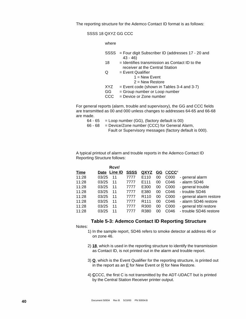
Document 50934 Rev B 5/15/00 PN 50934:B40
The reporting structure for the Ademco Contact ID format is as follows:
SSSS 18 QXYZ GG CCC
where
SSSS = Four digit Subscriber ID (addresses 17 - 20 and 43 - 46)
18 = Identifies transmission as Contact ID to the receiver at the Central Station
Q = Event Qualifier1 = New Event2 = New Restore
XYZ = Event code (shown in Tables 3-4 and 3-7)GG = Group number or Loop numberCCC = Device or Zone number
For general reports (alarm, trouble and supervisory), the GG and CCC fieldsare transmitted as 00 and 000 unless changes to addresses 64-65 and 66-68are made.
64 - 65 = Loop number (GG), (factory default is 00)66 - 68 = Device/Zone number (CCC) for General Alarm,
Fault or Supervisory messages (factory default is 000).
A typical printout of alarm and trouble reports in the Ademco Contact IDReporting Structure follows:
Time Date SSSS QXYZ GG CCCC4
11:28 03/25 11 7777 E110 00 C000 - general alarm11:28 03/25 11 7777 E111 00 C046 - alarm SD4611:28 03/25 11 7777 E300 00 C000 - general trouble11:28 03/25 11 7777 E380 00 C046 - trouble SD4611:28 03/25 11 7777 R110 00 C000 - general alarm restore11:28 03/25 11 7777 R111 00 C046 - alarm SD46 restore11:28 03/25 11 7777 R300 00 C000 - general trbl restore11:28 03/25 11 7777 R380 00 C046 - trouble SD46 restore
Table 5-3: Ademco Contact ID Reporting StructureNotes:
1) In the sample report, SD46 refers to smoke detector at address 46 oron zone 46.
2) 18, which is used in the reporting structure to identify the transmissionas Contact ID, is not printed out in the alarm and trouble report.
3) Q, which is the Event Qualifier for the reporting structure, is printed outin the report as an E for New Event or R for New Restore.
4) CCCC, the first C is not transmitted by the ADT-UDACT but is printedby the Central Station Receiver printer output.
Rcvr/Line ID

Document 50934 Rev B 5/15/00 PN 50934:B 41
By using the Type Mode feature, identification of zone/point types is possible. Limits for the maximumnumber of zones/points reported for each panel are as follows:
Unimode 300 = 192 points / 99 zonesUnimode 400 = 384 points / 99 zonesUnimode 2020/1010 = 568 pointsADT-MNNA = 568 points
#DIEPYT ECIVEDDETAVITCA #TNIOP/ENOZ TROPER
2 mralAyrosivrepuS 1 100C00002E
3 mralAnoitatSlluP 3 300C00511E
4 mralArosneStaeH 4 400C00411E
5 mralAwolfretaW 5 500C00311E
6 mralArotceteDtcuD 6 600C00611E
7 mralArosneSemalF 7 700C00711E
8 mralAenoZekomS)lanoitnevnoC(
2 200C00111E
9 yralgruB 8 800C00031E
A yralgrub-noNruoH42 9 900C00051E
B erutarepmeThgiH 01 010C00851E
C erutarepmeTwoL 11 110C00951E
D erusserPretaWwoL 21 210C00102E
E leveLretaWwoL 31 310C00402E
F eruliaFpmuP 41 410C00602E
................................ ................................. hguorht .................................
ANNM-TDAdna0101/0202edominUroftimiL 865
004edominUroftimiL 844

Document 50934 Rev B 5/15/00 PN 50934:B42
Format # (Addresses 16 & 42)
0 4+1 Ademco Express ✔✔✔✔✔ ✔ ✔ ✔ ✔ ✔ ✔✔✔✔✔
1 4+2 Ademco Express ✔✔✔✔✔ ✔ ✔ ✔ ✔ ✔ ✔ ✔ ✔ ✔ ✔ (8) ✔✔✔✔✔
2 3+1/Standard/1800/2300 ✔✔✔✔✔ ✔✔✔✔✔ (2) ✔ ✔ ✔ ✔ ✔ ✔ ✔ ✔ ✔ ✔ (4) ✔ ✔ ✔ ✔ ✔ ✔ ✔ ✔ ✔ ✔ (5,6) ✔ ✔ ✔ ✔ ✔ ✔✔✔✔✔
3 Not Used
4 3+1/Standard/1900/1400 ✔✔✔✔✔ ✔✔✔✔✔ (2) ✔ ✔ ✔ ✔ ✔ (4) ✔ ✔ ✔ ✔ ✔ ✔ ✔ ✔ ✔ ✔ ✔✔✔✔✔
5 Not Used
6 4+1/Standard/1800/2300 ✔✔✔✔✔ ✔✔✔✔✔ (2) ✔✔✔✔✔ ✔ ✔ ✔ ✔ ✔ (4) ✔ ✔ ✔ ✔ ✔ ✔ ✔ ✔ ✔ ✔ (5) ✔ ✔ ✔ ✔ ✔ ✔✔✔✔✔
7 Not Used
8 4+1/Standard/1900/1400 ✔✔✔✔✔ ✔✔✔✔✔ (2) ✔ ✔ ✔ ✔ ✔ (4) ✔ ✔ ✔ ✔ ✔ ✔ ✔ ✔ ✔ ✔ ✔✔✔✔✔
9 Not Used
A 4+2/Standard/1800/2300 ✔✔✔✔✔ ✔✔✔✔✔ (2) ✔✔✔✔✔ ✔ ✔ ✔ ✔ ✔ (4) ✔ ✔ ✔ ✔ ✔ ✔ ✔ ✔ ✔ ✔ (5) ✔ ✔ ✔ ✔ ✔ ✔✔✔✔✔
B Not Used
C 4+2/Standard/1900/1400 ✔✔✔✔✔ ✔ ✔ ✔ ✔ ✔ (2) ✔ ✔ ✔ ✔ ✔ (4) ✔ ✔ ✔ ✔ ✔ ✔ ✔ ✔ ✔ ✔ ✔✔✔✔✔
D Not Used
E Ademco Contact ID ✔✔✔✔✔ ✔ ✔ ✔ ✔ ✔ ✔ ✔ ✔ ✔ ✔ ✔✔✔✔✔
F Not Used
The chart below shows UL listed receivers compatible with the ADT-UDACT:
Ade
mco
685
(1)
Sile
nt K
nigh
t 9
000
ITI
CS
-400
0 (3
)
FB
IC
P22
0FB
Osb
orne
Hof
fman
Qui
ck A
lert
Mod
els
1 &
2
Rad
ioni
cs60
00/6
500
(5)
Line
ar/S
esco
a30
00R
(7)
(1) With 685-8 Line Card with Rev 4.4d software.(2) With 9002 Line Card Rev 9035 software or 9032 Line Card with 9326A software.(3) Rev. 4.0 software.(4) FBI CP220FB Rec-11 Line Card with Rev 2.6 software and a memory card with Rev 3.8 software.(5) Model 6500 with Rev 600 software.(6) Model 6000 with Rev 204 software.(7) With Rev B control card at Rev 1.4 software and Rev C line card at Rev 1.5 software.(8) Model 2 only.(9) Version 1.62 software.
6.0 Compatible Receivers
Sur
guar
dM
LR-2
(9)
Table 6-1: Compatible UL Listed Receivers

Document 50934 Rev B 5/15/00 PN 50934:B 43
7.0 Programming Reference Sheets--- To enter Programming, press Mode: 7 7 6 4, Enter
❑ 00 ❑ 01 ❑ 02 ❑ 03 ❑ 04 ❑ 05 ❑ 06 ❑ 07 ❑ 08 ❑ 09 ❑ 10 ❑ 11 ❑ 12 ❑ 13 ❑ 14 ❑ 15
Addresses 00 to 15 store the Primary Phone Number. Enter 'F' to represent the end of the number.
❑ 16 Primary Comm Format: Enter 0 - F.
❑ 17 ❑ 18 ❑ 19 ❑ 20 Primary Account Code: Valid keys are 0-F.
❑ 21 ❑ 22 ❑ 23 ❑ 24 Primary 24-Hour Test Time. Enter military time (i.e. 1400 for 2 PM).
❑ 25 Primary Number Test Time Interval. Enter '0' for 24-hour; '1' - 12-hour.
❑ 26 ❑ 27 ❑ 28 ❑ 29 ❑ 30 ❑ 31 ❑ 32 ❑ 33 ❑ 34 ❑ 35 ❑ 36 ❑ 37 ❑ 38 ❑ 39 ❑ 40 ❑ 41
Addresses 26-41 store the Secondary Phone Number. Enter 'F' to represent the end of the number.
❑ 42 Secondary Comm Format: Enter 0-F.
❑ 43 ❑ 44 ❑ 45 ❑ 46 Secondary Account Code: Valid keys are 0-F.
❑ 47 ❑ 48 ❑ 49 ❑ 50 Secondary 24-Hour Test Time. Enter military time (i.e. 1400 for 2 PM).
❑ 51 Secondary Number Test Time Interval. Enter '0' for 24-hour; '1' - 12-hour.
❑ 52 ❑ 53 Start Monitoring Address. Valid entries are 01 through 32.
❑ 54 ❑ 55 End Monitoring Address. Valid entries are 01 through 32.
❑ 56 ADT-UDACT Communication Selection. Enter '0' to disable ADT-UDACT communication; '1' for zone
reporting receive only communication; '2' for zone reporting receive/transmit communication; '3' for pointreporting receive only; or '4' for point reporting receive/transmit.
❑ 57 Backup Reporting. Enter '0' to have secondary phone number act as backup only; '1' to have secondary
phone number receive all reports and messages along with primary phone number.
❑ 58 Touchtone/Rotary Select. Enter '0' for touchtone dialing; '1' for rotary dialing.
❑ 59 Make/Break Ratio. If rotary dialing is selected in Address 58; Enter '0' for a 67/73 make/break ratio; '1'
for a 62/38 make/break ratio.
❑ 60 Leave default of 0.
❑ 61 Leave default of 0.
❑ 62 AC Loss Reporting Delay. Enter '0' for no time delay after AC loss; '1' for 6 hour delay; '2' for 7 hour
delay; '3' for 8 hour delay; '4' for 9 hour delay; '5' for 10 hour delay; '6' for 11 hour delay; '7' for 15 hourdelay; '8' for 16 hour delay; '9' for 17 hour delay; 'A' for 18 hour delay; 'B' for 19 hour delay; 'C' for 20hour delay; 'D' for 21 hour delay; 'E' for 22 hour delay; or 'F' for 23 hour delay.
❑ 63 Host Panel ID. Enter '7' for Unimode 2020/1010 and ADT-MNNA; '8' for Unimode 300/400; all other
entries are invalid.
❑ 64 ❑ 65 Loop Number. Factory set to '00'. Valid entries are 00 through 97
❑ 66 ❑ 67 ❑ 68 Device/Zone Number for General Reports. Factory set to '000'. Valid entries are 000
through 999.

Document 50934 Rev B 5/15/00 PN 50934:B44
❑ 69 ❑ 70 ❑ 71 ❑ 72 ❑ 73 ❑ 74 ❑ 75 ❑ 76 ❑ 77 ❑ 78 ❑ 79 ❑ 80 ❑ 81
❑82
❑83
❑84
❑85
❑86
❑87
❑88
❑89
❑90
❑91
❑92
❑93
❑94
❑ 95 ❑ 96 ❑ 97 ❑ 98 ❑ 99 ❑ 100 ❑ 101 ❑ 102 ❑ 103 ❑ 104 ❑ 105 ❑ 106 ❑ 107
❑ 108 ❑ 109 ❑ 110 ❑ 111 ❑ 112 ❑ 113 ❑ 114 ❑ 115 ❑ 116 ❑ 117 ❑ 118 ❑ 119 ❑ 120
❑121
❑122
❑123
❑124
❑125
❑126
❑127
❑128
❑129
❑130
❑131
❑132
❑133
❑ 134 ❑ 135 ❑ 136 ❑ 137 ❑ 138 ❑ 139 ❑ 140 ❑ 141 ❑ 142 ❑ 143 ❑ 144 ❑ 145 ❑ 146
❑ 147 ❑ 148 ❑ 149 ❑ 150 ❑ 151 ❑ 152 ❑ 153 ❑ 154 ❑ 155 ❑ 156 ❑ 157 ❑ 158 ❑ 159
❑160
❑161
❑162
❑163
❑164
❑165
❑166
❑167
❑168
❑169
❑170
❑171
❑172
❑ 173 ❑ 174 ❑ 175 ❑ 176 ❑ 177 ❑ 178 ❑ 179 ❑ 180 ❑ 181 ❑ 182 ❑ 183 ❑ 184 ❑ 185
❑ 186 ❑ 187 ❑ 188 ❑ 189 ❑ 190 ❑ 191 ❑ 192 ❑ 193 ❑ 194 ❑ 195 ❑ 196 ❑ 197 ❑ 198
❑199
❑200
❑201
❑202
❑203
❑204
❑205
❑206
❑207
❑208
Programming Reference Sheet

Document 50934 Rev B 5/15/00 PN 50934:B 45
Programming Reference Sheet Factory Default Settings--- To enter Programming, press Mode: 7 7 6 4, Enter
❑ 00 ❑ 01 ❑ 02 ❑ 03 ❑ 04 ❑ 05 ❑ 06 ❑ 07 ❑ 08 ❑ 09 ❑ 10 ❑ 11 ❑ 12 ❑ 13 ❑ 14 ❑ 15
Addresses 00 to 15 store the Primary Phone Number. Enter 'F' to represent the end of the number.
❑ 16 Primary Comm Format: (4+2 Standard 1800/2300).
❑ 17 ❑ 18 ❑ 19 ❑ 20 Primary Account Code.
❑ 21 ❑ 22 ❑ 23 ❑ 24 Primary 24-Hour Test Time. 0000 = 12:00 midnight.
❑ 25 Primary Number Test Time Interval. '0' for 24-hour.
❑ 26 ❑ 27 ❑ 28 ❑ 29 ❑ 30 ❑ 31 ❑ 32 ❑ 33 ❑ 34 ❑ 35 ❑ 36 ❑ 37 ❑ 38 ❑ 39 ❑ 40 ❑ 41
Addresses 26-41 store the Secondary Phone Number. Enter 'F' to represent the end of the number.
❑ 42 Secondary Comm Format: (4+2 Standard 1800/2300).
❑ 43 ❑ 44 ❑ 45 ❑ 46 Secondary Account Code.
❑ 47 ❑ 48 ❑ 49 ❑ 50 Secondary 24-Hour Test Time. 0000 = 12:00 midnight.
❑ 51 Secondary Number Test Time Interval. '0' for 24-hour.
❑ 52 ❑ 53 Start Monitoring Address
❑ 54 ❑ 55 End Monitoring Address
❑ 56 ADT-UDACT Communication Selection. '0' for ADT-UDACT Communication disabled.
❑ 57 Backup Reporting. '0' for backup.
❑ 58 Touchtone/Rotary Select. '0' for Touchtone.
❑ 59 Make/Break Ratio. '0' for 67/33 make/break ratio.
❑ 60 Leave default of zero.
❑ 61 Leave default of zero.
❑ 62 AC Loss reporting delay. '1' for 6 hour time delay.
❑ 63 Host PANEL ID. '8' for Unimode 300/400.
❑ 64 ❑ 65 Loop Number. For Ademco Contact ID only. Loop number = '00',
❑ 66 ❑ 67 ❑ 68 Device/Zone Number for general reports. For Ademco Contact ID only. Device number = '000'.
F F F F F
A
0
0
F F F F
0
0
0 00
000
0
0
0
0
0
0
0
0 0
0
F
F
A
0
0 2
1
1
8
0 0
0 0 0
F F F F F F F F F F
FFFFFFFFFFF
00
00
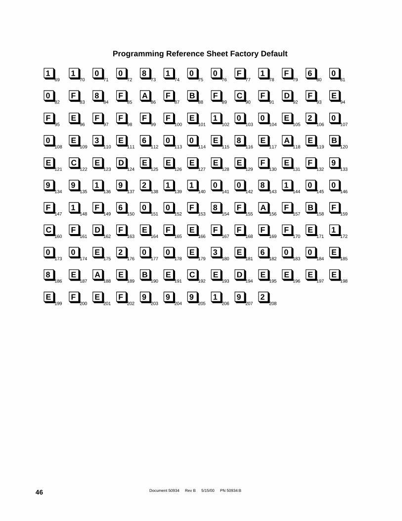
Document 50934 Rev B 5/15/00 PN 50934:B46
❑ 69 ❑ 70 ❑ 71 ❑ 72 ❑ 73 ❑ 74 ❑ 75 ❑ 76 ❑ 77 ❑ 78 ❑ 79 ❑ 80 ❑ 81
❑82
❑83
❑84
❑85
❑86
❑87
❑88
❑89
❑90
❑91
❑92
❑93
❑94
❑ 95 ❑ 96 ❑ 97 ❑ 98 ❑ 99 ❑ 100 ❑ 101 ❑ 102 ❑ 103 ❑ 104 ❑ 105 ❑ 106 ❑ 107
❑ 108 ❑ 109 ❑ 110 ❑ 111 ❑ 112 ❑ 113 ❑ 114 ❑ 115 ❑ 116 ❑ 117 ❑ 118 ❑ 119 ❑ 120
❑121
❑122
❑123
❑124
❑125
❑126
❑127
❑128
❑129
❑130
❑131
❑132
❑133
❑ 134 ❑ 135 ❑ 136 ❑ 137 ❑ 138 ❑ 139 ❑ 140 ❑ 141 ❑ 142 ❑ 143 ❑ 144 ❑ 145 ❑ 146
❑ 147 ❑ 148 ❑ 149 ❑ 150 ❑ 151 ❑ 152 ❑ 153 ❑ 154 ❑ 155 ❑ 156 ❑ 157 ❑ 158 ❑ 159
❑160
❑161
❑162
❑163
❑164
❑165
❑166
❑167
❑168
❑169
❑170
❑171
❑172
❑ 173 ❑ 174 ❑ 175 ❑ 176 ❑ 177 ❑ 178 ❑ 179 ❑ 180 ❑ 181 ❑ 182 ❑ 183 ❑ 184 ❑ 185
❑ 186 ❑ 187 ❑ 188 ❑ 189 ❑ 190 ❑ 191 ❑ 192 ❑ 193 ❑ 194 ❑ 195 ❑ 196 ❑ 197 ❑ 198
❑199
❑200
❑201
❑202
❑203
❑204
❑205
❑206
❑207
❑208
1 1 0 0 8 1 0 0 F 1 F 6 0
0 F 8 F A F B F C F D F E
F E F F F F E 1 0 0 E 2 0
0 E 3 E 6 0 0 E 8 E A E B
E C E D E E E E E F E F 9
9 9 1 9 2 1 1 0 0 8 1 0 0
F 1 F 6 0 0 F 8 F A F B F
C F D F E F E F F F F E 1
0 0 E 2 0 0 E 3 E 6 0 0 E
8 E A E B E C E D E E E E
E F E F 9 9 9 1 9 2
Programming Reference Sheet Factory Default
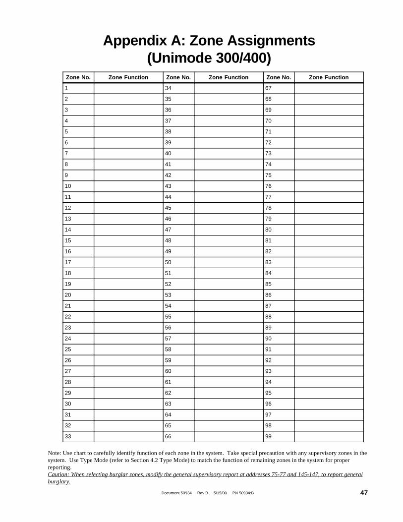
Document 50934 Rev B 5/15/00 PN 50934:B 47
Appendix A: Zone Assignments(Unimode 300/400)
Note: Use chart to carefully identify function of each zone in the system. Take special precaution with any supervisory zones in thesystem. Use Type Mode (refer to Section 4.2 Type Mode) to match the function of remaining zones in the system for properreporting.Caution: When selecting burglar zones, modify the general supervisory report at addresses 75-77 and 145-147, to report generalburglary.
Zone No. Zone Function Zone No. Zone Function Zone No. Zone Function
1 34 67
2 35 68
3 36 69
4 37 70
5 38 71
6 39 72
7 40 73
8 41 74
9 42 75
10 43 76
11 44 77
12 45 78
13 46 79
14 47 80
15 48 81
16 49 82
17 50 83
18 51 84
19 52 85
20 53 86
21 54 87
22 55 88
23 56 89
24 57 90
25 58 91
26 59 92
27 60 93
28 61 94
29 62 95
30 63 96
31 64 97
32 65 98
33 66 99
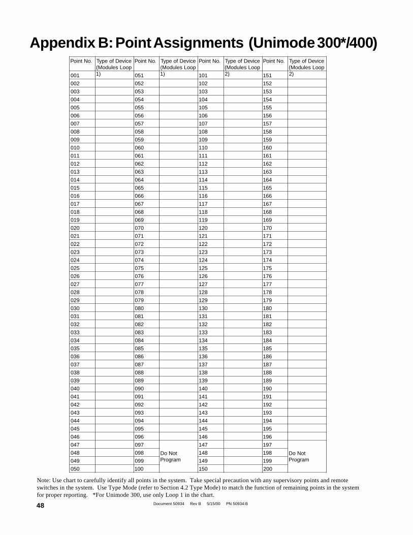
Document 50934 Rev B 5/15/00 PN 50934:B48
Appendix B: Point Assignments (Unimode 300*/400).oNtnioP eciveDfoepyT
pooLseludoM()1
.oNtnioP eciveDfoepyTpooLseludoM(
)1
.oNtnioP eciveDfoepyTpooLseludoM(
)2
.oNtnioP eciveDfoepyTpooLseludoM(
)2100 150 101 151
200 250 201 251
300 350 301 351
400 450 401 451
500 550 501 551
600 650 601 651
700 750 701 751
800 850 801 851
900 950 901 951
010 060 011 061
110 160 111 161
210 260 211 261
310 360 311 361
410 460 411 461
510 560 511 561
610 660 611 661
710 760 711 761
810 860 811 861
910 960 911 961
020 070 021 071
120 170 121 171
220 270 221 271
320 370 321 371
420 470 421 471
520 570 521 571
620 670 621 671
720 770 721 771
820 870 821 871
920 970 921 971
030 080 031 081
130 180 131 181
230 280 231 281
330 380 331 381
430 480 431 481
530 580 531 581
630 680 631 681
730 780 731 781
830 880 831 881
930 980 931 981
040 090 041 091
140 190 141 191
240 290 241 291
340 390 341 391
440 490 441 491
540 590 541 591
640 690 641 691
740 790
toNoDmargorP
741 791
toNoDmargorP
840 890 841 891
940 990 941 991
050 001 051 002
Note: Use chart to carefully identify all points in the system. Take special precaution with any supervisory points and remoteswitches in the system. Use Type Mode (refer to Section 4.2 Type Mode) to match the function of remaining points in the systemfor proper reporting. *For Unimode 300, use only Loop 1 in the chart.

Document 50934 Rev B 5/15/00 PN 50934:B 49
Appendix B (continued): Point Assignments (Unimode 300*/400).oNtnioP eciveDfoepyT
)1pooLsrotceteD(.oNtnioP eciveDfoepyT
)1pooLsrotceteD(.oNtnioP eciveDfoepyT
)2pooLsrotceteD(.oNtnioP eciveDfoepyT
)2pooLsrotceteD(
102 152 103 153
202 252 203 253
302 352 303 353
402 452 403 453
502 552 503 553
602 652 603 653
702 752 703 753
802 852 803 853
902 952 903 953
012 062 013 063
112 162 113 163
212 262 213 263
312 362 313 363
412 462 413 463
512 562 513 563
612 662 613 663
712 762 713 763
812 862 813 863
912 962 913 963
022 072 023 073
122 172 123 173
222 272 223 273
322 372 323 373
422 472 423 473
522 572 523 573
622 672 623 673
722 772 723 773
822 872 823 873
922 972 923 973
032 082 033 083
132 182 133 183
232 282 233 283
332 382 333 383
432 482 433 483
532 582 533 583
632 682 633 683
732 782 733 783
832 882 833 883
932 982 933 983
042 092 043 093
142 192 143 193
242 292 243 293
342 392 343 393
442 492 443 493
542 592 543 593
642 692 643 693
742 792
margorPtoNoD
743 793
margorPtoNoD842 892 843 893
942 992 943 993
052 003 053 004
Note: Addressable detectors on Loops 1 and 2 may be disabled using Type Mode. The Event Code cannot be altered.*For Unimode 300, use only Loop 1 in the chart.
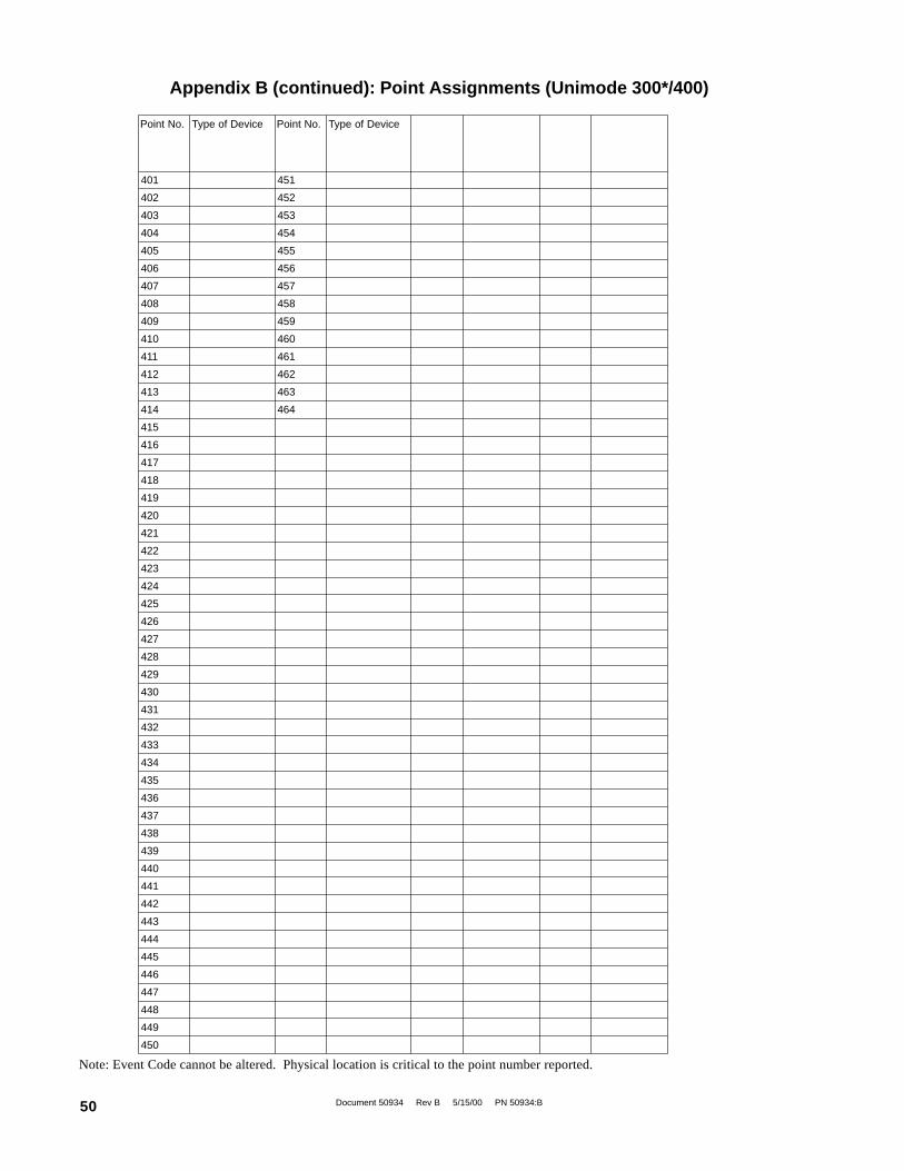
Document 50934 Rev B 5/15/00 PN 50934:B50
Appendix B (continued): Point Assignments (Unimode 300*/400)
.oNtnioP eciveDfoepyT .oNtnioP eciveDfoepyT
104 154
204 254
304 354
404 454
504 554
604 654
704 754
804 854
904 954
014 064
114 164
214 264
314 364
414 464
514
614
714
814
914
024
124
224
324
424
524
624
724
824
924
034
134
234
334
434
534
634
734
834
934
044
144
244
344
444
544
644
744
844
944
054
Note: Event Code cannot be altered. Physical location is critical to the point number reported.

Document 50934 Rev B 5/15/00 PN 50934:B 51
Appendix C: Point Assignments (ADT-MNNA)
Point No. Point Function Point No. Point Function Point No. Point Function
1 41 81
2 42 82
3 43 83
4 44 84
5 45 85
6 46 86
7 47 87
8 48 88
9 49 89
10 50 90
11 51 91
12 52 92
13 53 93
14 54 94
15 55 95
16 56 96
17 57 97
18 58 98
19 59 99
20 60 100
21 61 101
22 62 102
23 63 103
24 64 104
25 65 105
26 66 106
27 67 107
28 68 108
29 69 109
30 70 110
31 71 111
32 72 112
33 73 113
34 74 114
35 75 115
36 76 116
37 77 117
38 78 118
39 79 119
40 80 120
Note: Use the following charts to carefully identify the function of each point in the system. Take special precaution with anysupervisory points in the system. For the ADT-UDACT to report a supervisory point to the central station, both the FACP and theADT-UDACT must have the point programmed as supervisory. Failure to program the panel or ADT-UDACT correctly will resultin a fire alarm signal being transmitted to the central station. All points greater than 568 can only be transmitted as fire alarmpoints. Use Type Mode (refer to Section 4.2 Type Mode) to match the function of points in the system for proper reporting.
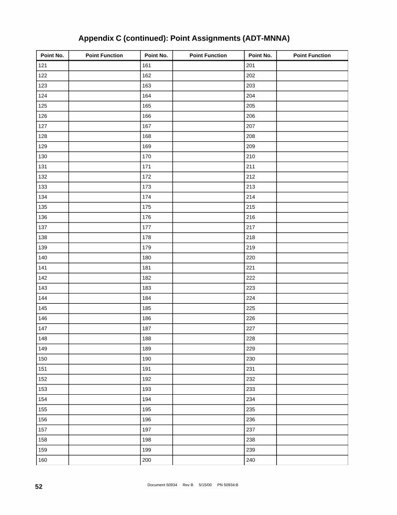
Document 50934 Rev B 5/15/00 PN 50934:B52
Point No. Point Function Point No. Point Function Point No. Point Function
121 161 201
122 162 202
123 163 203
124 164 204
125 165 205
126 166 206
127 167 207
128 168 208
129 169 209
130 170 210
131 171 211
132 172 212
133 173 213
134 174 214
135 175 215
136 176 216
137 177 217
138 178 218
139 179 219
140 180 220
141 181 221
142 182 222
143 183 223
144 184 224
145 185 225
146 186 226
147 187 227
148 188 228
149 189 229
150 190 230
151 191 231
152 192 232
153 193 233
154 194 234
155 195 235
156 196 236
157 197 237
158 198 238
159 199 239
160 200 240
Appendix C (continued): Point Assignments (ADT-MNNA)
Document 50934 Rev B 5/15/00 PN 50934:B 53
Point No. Point Function Point No. Point Function Point No. Point Function
241 281 321
242 282 322
243 283 323
244 284 324
245 285 325
246 286 326
247 287 327
248 288 328
249 289 329
250 290 330
251 291 331
252 292 332
253 293 333
254 294 334
255 295 335
256 296 336
257 297 337
258 298 338
259 299 339
260 300 340
261 301 341
262 302 342
263 303 343
264 304 344
265 305 345
266 306 346
267 307 347
268 308 348
269 309 349
270 310 350
271 311 351
272 312 352
273 313 353
274 314 354
275 315 355
276 316 356
277 317 357
278 318 358
279 319 359
280 320 360
Appendix C (continued): Point Assignments (ADT-MNNA)
Document 50934 Rev B 5/15/00 PN 50934:B54
Point No. Point Function Point No. Point Function Point No. Point Function
361 401 441
362 402 442
363 403 443
364 404 444
365 405 445
366 406 446
367 407 447
368 408 448
369 409 449
370 410 450
371 411 451
372 412 452
373 413 453
374 414 454
375 415 455
376 416 456
377 417 457
378 418 458
379 419 459
380 420 460
381 421 461
382 422 462
383 423 463
384 424 464
385 425 465
386 426 466
387 427 467
388 428 468
389 429 469
390 430 470
391 431 471
392 432 472
393 433 473
394 434 474
395 435 475
396 436 476
397 437 477
398 438 478
399 439 479
400 440 480
Appendix C (continued): Point Assignments (ADT-MNNA)

Document 50934 Rev B 5/15/00 PN 50934:B 55
Point No. Point Function Point No. Point Function Point No. Point Function
481 521 561
482 522 562
483 523 563
484 524 564
485 525 565
486 526 566
487 527 567
488 528 568
489 529
490 530
491 531
492 532
493 533
494 534
495 535
496 536
497 537
498 538
499 539
500 540
501 541
502 542
503 543
504 544
505 545
506 546
507 547
508 548
509 549
510 550
511 551
512 552
513 553
514 554
515 555
516 556
517 557
518 558
519 559
520 560
Appendix C (continued): Point Assignments (ADT-MNNA)

Document 50934 Rev B 5/15/00 PN 50934:B56
The ADT-UDACT is capable of reporting up to 2,040 points when used with the Unimode2020/1010 (1,980 Addressable devices plus 60 zones or 1,800 Addressable devices plus240 zones) The first 568 points can be programmed using the Type Mode feature (refer toSection 4.2). All points greater than 568 can be transmitted only as fire alarm points. Forthe ADT-UDACT to report a supervisory point to the central station, both the FACP andthe ADT-UDACT must have the point programmed as supervisory. Failure to program thepanel or ADT-UDACT correctly will result in a fire alarm signal being transmitted to thecentral station.
The ADT-UDACT may be mounted in the Unimode 2020/1010 control panel using theCHS-4 chassis or remotely in an ADT-ABS-8RF or ADT-UBS-1F enclosure up to 6000feet away from the control panel. All power must be removed from the control panel beforemaking any connections to prevent circuit damage. The EIA-485 serial interface is connectedbetween the control panel and ADT-UDACT using twisted, shielded pair wire. Power shouldbe wired from the control panel's main power supply 24 VDC (nominal) filtered, nonresettableoutput to TB1 on the ADT-UDACT.
Note: The ADT-UDACT does not support voice and burglar options when used with theUnimode 2020/1010. Refer to the Unimode 2020/1010Manual for additional restrictions.
ADT-UDACT mounting in a Unimode 2020/1010Remove all power from the FACP by disconnecting AC and batteries. Install the three supplied nylon support posts forthe top and bottom left of the ADT-UDACT, one aluminum/nylon and one aluminum standoff in the CHS-4 chassis slotin which the ADT-UDACT is to be installed (refer to Figure D-2). Position the ADT-UDACT on the standoffs and secureon aluminum standoff with a #6-32 screw.
Connect the communication line between the EIA-485 terminal block on the Unimode 2020/1010 SIB card and TB-1terminals 3 and 4 on the ADT-UDACT being certain to observe polarity (refer to Figure D-3). Recommended wire is12 AWG to 18 AWG twisted pair. If no other devices are connected to the EIA-485, install a 120 ohm EOL resistoracross ADT-UDACT TB1 terminals 3 and 4.
Connect the supplied Ground Strap from the ADT-UDACT Earth Ground terminal on TB3 to the CHS-4 chassis. Connect24 VDC filtered, regulated power to TB1 terminals 1 and 2 on the ADT-UDACT.
Appendix D: Unimode 2020/1010
Figure D-2: ADT-UDACT Mounting in CHS-4
CHS-4
ADT-UDACT
Nylon Support Posts
Ground Strap
Nylon and Aluminum Standoff
Aluminum Standoff and Screw
Figure D-1:ADT-UBS-1F
6708
ubs.
wm
f
UD
AC
CH
S4.
WM
F
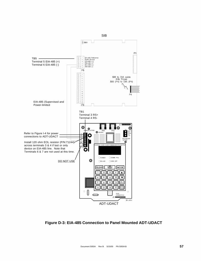
Document 50934 Rev B 5/15/00 PN 50934:B 57
TB1Terminal 3 RS+Terminal 4 RS-
SIB
ADT-UDACT
EIA-485 (Supervised andPower-limited
Figure D-3: EIA-485 Connection to Panel Mounted ADT-UDACT
TB5Terminal 5 EIA-485 (+)Terminal 6 EIA-485 (-)
Refer to Figure I-4 for powerconnections to ADT-UDACT
Install 120 ohm EOL resistor (P/N:71244)across terminals 3 & 4 if last or onlydevice on EIA-485 line. Note thatTerminals 6 & 7 are not used at this time.
DO NOT USE

Document 50934 Rev B 5/15/00 PN 50934:B58
SIB in Unimode 2020/1010
(Supervised)To PhoneLines Solid Earth Ground Connection
Install 120 ohm EOL resistor (P/N:71244)across terminals 3 & 4 if last or onlydevice on EIA-485 line. Note thatTerminals 6 & 7 are not used at this time.
Notes:
1) Ferrite cores are recommended for all applications.
2) Recommended wire is 12 AWG to 18 AWG twisted pair.
3) Shielded wire is not required (unless mandated by local AHJ).If shielded wire is used, connect only one end of shield:a) shield may be connected to cabinet (earth ground) at fire alarm panel, orb) shield may be connected to TB1 Terminal 5 (Shield) at ADT-UDACT as shown in Figure D-4.NOTE: The shield end that is not connected should be insulated to prevent accidental grounding.Do not connect both ends of shield under any circumstance since a ground fault may result.
4) Conduit is recommended for external wire runs. Consult local building codes.
5) Connect Ground Strap (supplied with ADT-ABS8RF enclosure) from Earth Ground terminal onADT-UDACT to a solid building earth ground. Conduit alone will not provide a reliable earth ground.
6) ADT-UDACT may be located up to 6000 feet away from the host control panel.
7) Refer to Specifications for power requirements.
Figure D-4: EIA-485 Connection to Remote ADT-UDACT
ADT-UDACT inADT-ABS8RF
(Shown with cover removed)
Unimode 2020/1010 cabinet
DO NOT USE
AM
20A
BS
U.W
MF

Document 50934 Rev B 5/15/00 PN 50934:B 59
Figure E-2: ADT-CPU-400 Module
The ADT-UDACT is capable of reporting a maximum of 99zones or 448 points when used with the Unimode 400.
The ADT-UDACT must be mounted remotely in an ADT-ABS8RFor ADT-UBS-1 enclosure up to 6000 feet away from the controlpanel. All power must be removed from the Control Panel beforemaking any connections to prevent circuit damage. The EIA-485serial interface is connected between the Control Panel and ADT-UDACT using twisted, shielded pair wire. Power should be wiredfrom the MPS-400 24 VDC nonresettable output to TB1 on theADT-UDACT.
Remove all power from the control panel by disconnecting AC andbatteries. Since the Unimode 400 cannot accommodate the ADT-UDACT in the control panel enclosure, the ADT-UDACT mustbe mounted remotely using an ADT-ABS8RF enclosure. Ferritecores are recommended for this application. Refer to Figure E-3and the accompanying notes for wiring alternatives.
Connect the communication line between the EIA-485 terminal block TB4 on theUnimode 300/400 and TB-1 terminals 3 and 4 on the ADT-UDACT, being certain toobserve polarity (refer to Figure E-3). Recommended wire is 12 AWG to 18 AWG twistedpair. If no other devices are connected to the EIA-485, install a 120 ohm EOL resistoracross ADT-UDACT TB1 terminals 3 and 4.
Connect the supplied ground strap from the ADT-UDACT Earth Ground terminal onTB3 to a solid building earth ground. Connect 24VDC nonresettable power to TB-1terminals 1 and 2 on the ADT-UDACT (refer to Figure E-3).
SY STEMRES ET
L AM PTES T
SY STEMTROUB LE
DISABLE DPO INTS
ALARMSILE NC ED
SU PERVISO RYSIG NAL
Appendix E: Unimode 300/400
AB
S-8
R.W
MF
Figure E-1:ADT-ABS8RF
AB
S-8
R.W
MF
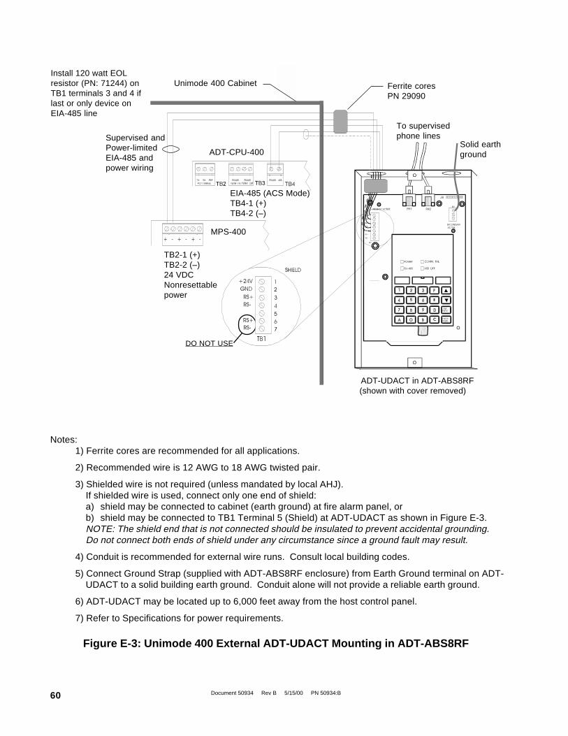
Document 50934 Rev B 5/15/00 PN 50934:B60
Notes:1) Ferrite cores are recommended for all applications.
2) Recommended wire is 12 AWG to 18 AWG twisted pair.
3) Shielded wire is not required (unless mandated by local AHJ).If shielded wire is used, connect only one end of shield:a) shield may be connected to cabinet (earth ground) at fire alarm panel, orb) shield may be connected to TB1 Terminal 5 (Shield) at ADT-UDACT as shown in Figure E-3.NOTE: The shield end that is not connected should be insulated to prevent accidental grounding.Do not connect both ends of shield under any circumstance since a ground fault may result.
4) Conduit is recommended for external wire runs. Consult local building codes.
5) Connect Ground Strap (supplied with ADT-ABS8RF enclosure) from Earth Ground terminal on ADT-UDACT to a solid building earth ground. Conduit alone will not provide a reliable earth ground.
6) ADT-UDACT may be located up to 6,000 feet away from the host control panel.
7) Refer to Specifications for power requirements.
EIA-485 (ACS Mode)TB4-1 (+)TB4-2 (–)
MPS-400
ADT-CPU-400
TB2-1 (+)TB2-2 (–)24 VDCNonresettablepower
Ferrite coresPN 29090
Unimode 400 CabinetInstall 120 watt EOLresistor (PN: 71244) onTB1 terminals 3 and 4 iflast or only device onEIA-485 line
Supervised andPower-limitedEIA-485 andpower wiring
To supervisedphone lines
Solid earthground
ADT-UDACT in ADT-ABS8RF(shown with cover removed)
DO NOT USE
Figure E-3: Unimode 400 External ADT-UDACT Mounting in ADT-ABS8RF

Document 50934 Rev B 5/15/00 PN 50934:B 61
Type Mode Programming
To disable or identify a zone or point in Type Mode (refer to Section 4.2), the following Entries/Addresses are used:
For Zone Identification:
Zones 1 - 99 are programmed by Entries/Addresses 01 - 99. The factory default code is 'fire alarm.'
For Point Identification:
Loop 1, Modules 101 - 196 are programmed by Type Mode Entries/Addresses 01 - 96Loop 2 Modules 201 - 296 are programmed by Type Mode Entries/Addresses 101 - 196Loop 1, Detectors 101 - 196 are programmed by Type Mode Entries/Addresses 201 - 296Loop 2, Detectors 201 - 296 are programmed by Type Mode Entries/Addresses 301 - 396System 5000 output modules are programmed by Type Mode Entries/Addresses 401 - 464
CAUTION: Addresses 97 - 100, 197 - 200 and 297 - 300 must not be programmed. Refer to the CAB illustrations below.
Event Code/Report Transmissionvia Ademco Contact ID Format Only
For Zone Reporting:
Zones 1 - 99 report as zone numbers 01 - 99
For Point Reporting:
Loop 1, Modules 101 - 196 report as device numbers 01 - 96 (Report defaults to '110')Loop 2, Modules 201 - 296 report as device numbers 101 - 196 (Report defaults to '110')Loop 1, Detectors 101 - 196 report as device numbers 201 - 296 (Report defaults to '111')Loop 2, Detectors 201 - 296 report as device numbers 301 - 396 (Report defaults to '111')Output Modules 1 - 64 report as device numbers 401 - 464 (Report defaults to '380', trouble only)
CAUTION: Point reports for Loop 1, Modules 197 through 199, Detectors 197 through 199 and point reports for Loop2, Modules 297 through 299 and Detectors 297 through 299 are omitted. However, when devices are installed on eitherSLC Loop and the device is in alarm or trouble, the ADT-UDACT will transmit the general alarm and general troublereports if enabled.
Following are module locations and their corresponding addresses in various cabinets:
UPC004-PFA 424-714 234-524
044-334 844-144 654-944 464-754
UPC004-PFA
804-104 614-904 424-714 234-524
044-334 844-144 654-944 464-754
UPC004-PFA 804-104
ADT-CAB - B3 ADT-CAB - C3 ADT-CAB - 400AA

Document 50934 Rev B 5/15/00 PN 50934:B62
The ADT-UDACT is capable of reporting up to 2,040 points when used with the ADT-MNNA. The first 568 points canbe programmed using the Type Mode feature (refer to Section 4.2). All points greater than 568 can be transmitted onlyas fire alarm points. For the ADT-UDACT to report a supervisory point to the central station, both the FACP and theADT-UDACT must have the point programmed as supervisory. Failure to program the panel or ADT-UDACT correctlywill result in a fire alarm signal being transmitted to the central station.
The ADT-UDACT may be mounted in the ADT-MNNA control panel using the CHS-4 chassis or remotely in an ADT-ABS8RF or ADT-UBS-1 enclosure up to 6,000 feet away from the control panel. All power must be removed from thecontrol panel before making any connections to prevent circuit damage. The EIA-485 serial interface is connected betweenthe control panel and ADT-UDACT using twisted, shielded pair wire. Power should be wired from the control panel'smain power supply 24 VDC (nominal) filtered, nonresettable output to TB1 on the ADT-UDACT.Note: The ADT-UDACT does not support voice and burglar options when used with the ADT-MNNA. Refer to the ADT-MNNA Manual for additional restrictions.
ADT-UDACT mounting in an ADT-MNNARemove all power from the ADT-MNNA by disconnecting AC and batteries. Install the three supplied nylon supportposts for the top and bottom left of the ADT-UDACT, one aluminum/nylon and one aluminum standoff in the CHS-4chassis slot in which the ADT-UDACT is to be installed. Position the ADT-UDACT on the standoffs and secure onaluminum standoff with a #6-32 screw.
Connect the communication line between the EIA-485 terminal block on the ADT-MNNA and TB-1 terminals 3 and 4 onthe ADT-UDACT being certain to observe polarity (refer to Figure F-1). Recommended wire is 12 AWG to 18 AWGtwisted pair. If no other devices are connected to the EIA-485, install a 120 ohm EOL resistor across ADT-UDACT TB1terminals 3 and 4.
Connect the supplied Ground Strap from the ADT-UDACT Earth Ground terminal on TB3 to the CHS-4 chassis. Connect24 VDC filtered power to TB1 terminals 1 and 2 on the ADT-UDACT.
Appendix F: ADT-MNNA
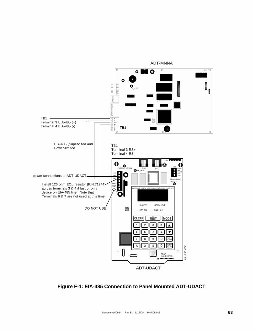
Document 50934 Rev B 5/15/00 PN 50934:B 63
ina-
udac
.wm
f
TB1Terminal 3 RS+Terminal 4 RS-
ADT-MNNA
ADT-UDACT
EIA-485 (Supervised andPower-limited
Figure F-1: EIA-485 Connection to Panel Mounted ADT-UDACT
TB1Terminal 3 EIA-485 (+)Terminal 4 EIA-485 (-)
power connections to ADT-UDACT
Install 120 ohm EOL resistor (P/N:71244)across terminals 3 & 4 if last or onlydevice on EIA-485 line. Note thatTerminals 6 & 7 are not used at this time.
DO NOT USE
TB1
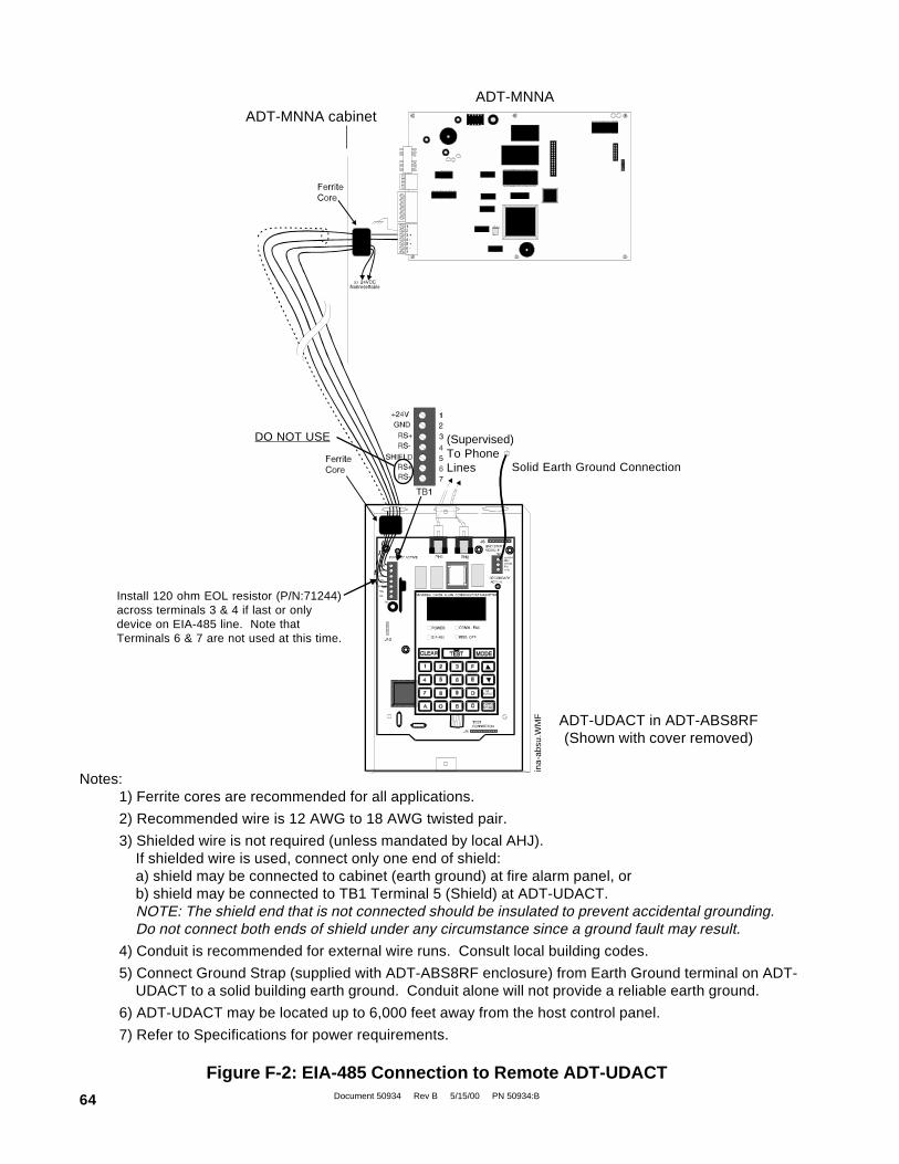
Document 50934 Rev B 5/15/00 PN 50934:B64
ADT-MNNA
(Supervised)To PhoneLines Solid Earth Ground Connection
Install 120 ohm EOL resistor (P/N:71244)across terminals 3 & 4 if last or onlydevice on EIA-485 line. Note thatTerminals 6 & 7 are not used at this time.
Notes:1) Ferrite cores are recommended for all applications.
2) Recommended wire is 12 AWG to 18 AWG twisted pair.
3) Shielded wire is not required (unless mandated by local AHJ).If shielded wire is used, connect only one end of shield:a) shield may be connected to cabinet (earth ground) at fire alarm panel, orb) shield may be connected to TB1 Terminal 5 (Shield) at ADT-UDACT.NOTE: The shield end that is not connected should be insulated to prevent accidental grounding.Do not connect both ends of shield under any circumstance since a ground fault may result.
4) Conduit is recommended for external wire runs. Consult local building codes.
5) Connect Ground Strap (supplied with ADT-ABS8RF enclosure) from Earth Ground terminal on ADT-UDACT to a solid building earth ground. Conduit alone will not provide a reliable earth ground.
6) ADT-UDACT may be located up to 6,000 feet away from the host control panel.
7) Refer to Specifications for power requirements.
Figure F-2: EIA-485 Connection to Remote ADT-UDACT
ADT-UDACT in ADT-ABS8RF(Shown with cover removed)
ADT-MNNA cabinet
DO NOT USE
ina-
absu
.WM
F

Document 50934 Rev B 5/15/00 PN 50934:B 65
Appendix G: Annunciators
The ADT-UDACT is connected to the EIA-485 communication bus. AFM series and LDM series annunciators may alsooccupy the same bus. Use of an ADT-UDACT along with one of the above mentioned annunciators on the same controlpanel will alter the assignments of the first eight yellow LEDs on the annunciator as follows:
Note: When using a ADT-UDACT with the Unimode 2020/1010 or ADT-MNNA, the first Red LED on an annunciator isused to annunciate alarms while LEDs 2 through 8 are not used.
004/003edominU
DELrotaicnunnAwolleY tnemngissATCADUtuohtiW
tnemngissATCADUhtiW
1elbuorTmetsyS
)ssolCAtpecxe(elbuorTmetsyS
)ssolCAtpecxe(
2 decneliSslangiS decneliSslangiS
3 desUtoN edoMmargorP
4 desUtoN yrosivrepuS
5 yrosivrepuS elbuorTlleB
6 mralaerP/mralaerP
trelAecnanetniaM
7 liaFCA yrettaBwoL
8 elbuorTlenaP liaFCA
ANNM-TDA,0101/0202edominU
DELrotaicnunnAwolleY tnemngissATCADUtuohtiW
tnemngissATCADUhtiW
1 elbammargorPelbuorTmetsyS
).vpus&.ttab,ssolCAssel(
2 elbammargorP desUtoN
3 elbammargorP edoMmargorP
4 elbammargorP yrosivrepuS
5 elbammargorP desUtoN
6 elbammargorP )esuerutuf(trelAecnanetniaM
7 elbammargorP yrettaBoN/yrettaBwoL
8 elbammargorP liaFCA

Document 50934 Rev B 5/15/00 PN 50934:B66

Document 50934 Rev B 5/15/00 PN 50934:B 67

Document 50934 Rev B 5/15/00 PN 50934:B68